Iwatsu America ADIX-BS UPCS Base Station User Manual EBA 2000 28 SW V 7 00 Omegatrek Tech
Iwatsu America Inc UPCS Base Station EBA 2000 28 SW V 7 00 Omegatrek Tech
UserManual.wiki
>
Iwatsu America
>
ADIX BS User Manual
Users Manual
Navigation menu
Upload a User Manual
Namespaces
Wiki Guide
HTML
PDF
Info
Views
User Manual
Discussion / Help
Navigation
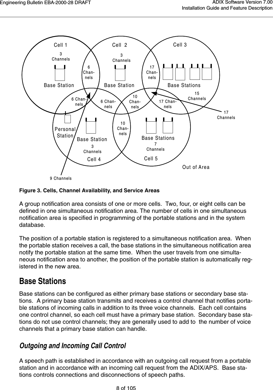

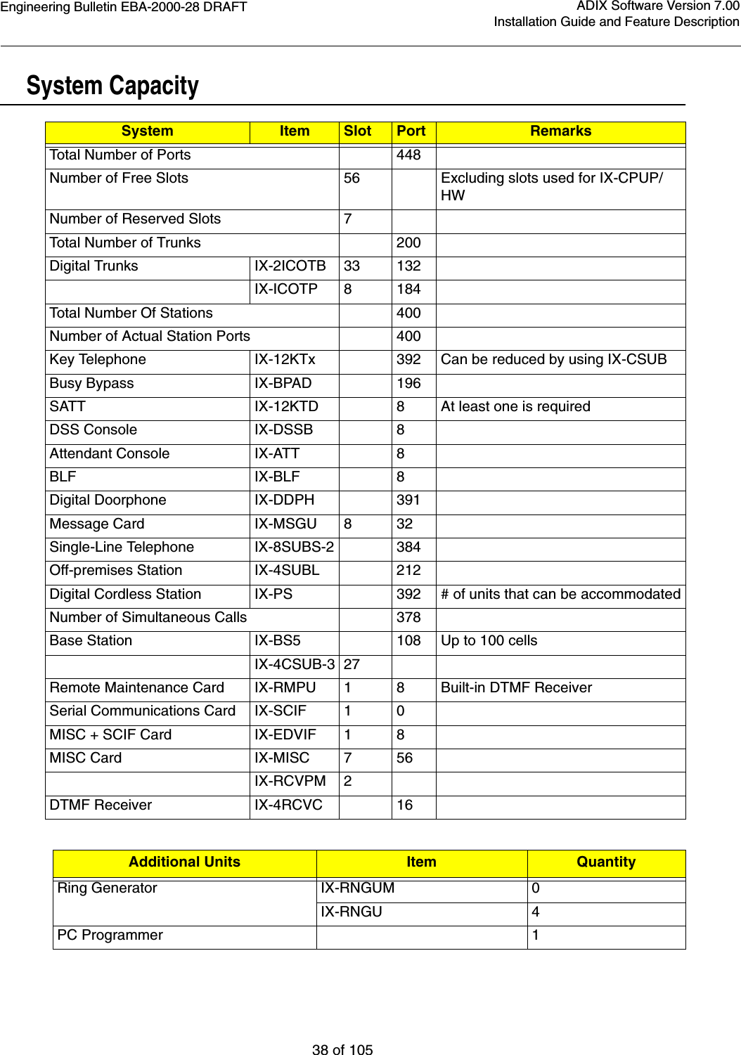
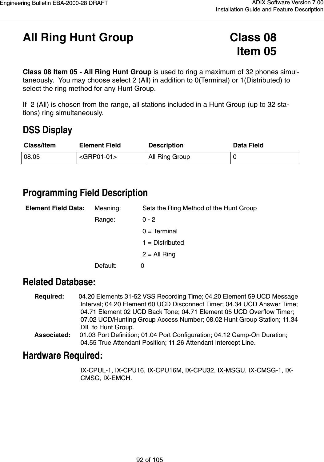
![Engineering Bulletin EBA-2000-28 DRAFT16 of 105ADIX Software Version 7.00Installation Guide and Feature Description•Universal Night Answer (UNA). This feature allows you to answer calls that have been switched to ring at the Night Mode location.•Direct Inward System Access (DISA). Direct Inward System Access (DISA) allows an exter-nal caller to access Omegatrek intercom dial tone by dialing the phone number of an outside line that is dedicated for DISA. DISA gives the external caller the ability to make intercom, hunt group, and external calls, and also have access to the paging system. Use of DISA for external calls and paging requires the entry of a security code to control fraudulent use.•Off-Hook Outside Line Answering. This feature allows a station user to answer an outside call without having to press the button representing the ringing line. The station user can still access other system features using CO/ICM line selection while an incoming call is ringing.• Manual Outside Line Answering. This feature allows a station user to answer an outside call by pressing the button representing the ringing line.Hold/Transfer/Conference Features•Conference. Omegatrek allows you to converse with three other people in one conversation. There may be any combination of inside extensions or outside lines.• Hold/Hold Recall. A call can be put on hold by pressing the [HOLD/DND] button. Calls that remain on hold for a programmable amount of time recall. The ringing tone for recall differs from the ringing tone of an incoming call. Recalls that are not picked up are automatically for-warded to the attendant. •Call Park/Swap and Call Park Pick-Up. Call Park/Swap allows you to alternate between two conversations. Call Park Pick-Up allows you to answer a call ringing at someone else's phone.• Group Park. When a station places a call on group park, a station's [Group Park] button rep-resenting that group will flash red. A station can pick up the call by pressing [Group Park]. If the call is not picked up within the duration programmed, the station that originally placed the call on group park is recalled.•Transfer to Park (Call Park at Another Extension). The Omegatrek system allows you to place a call on park at another user’s extension from your portable station.•Call Transfer. There are two ways a station user can transfer a call:•Screened Transfer. The call is transferred after the transferring station announces the call.•Unscreened Transfer. The call is transferred without being announced.•Accessing Guest Mailbox. This feature accommodates the Guest Mailbox feature provided by many voice mail systems. It allows access to mailboxes that are not associated with spe-cific ADIX extensions. The guest mailbox may be accessed from any system extension.](https://usermanual.wiki/Iwatsu-America/ADIX-BS/User-Guide-130613-Page-16.png)
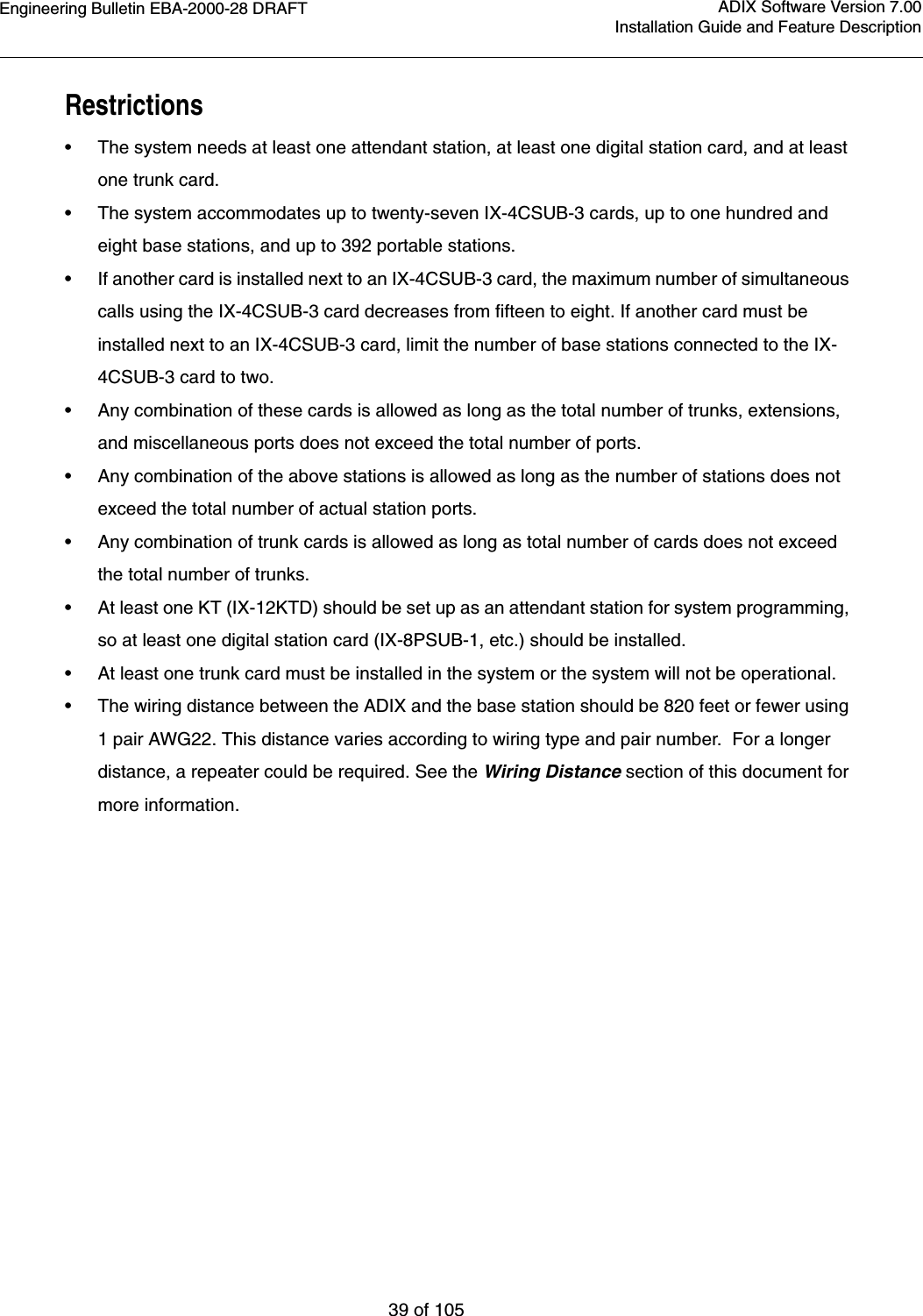
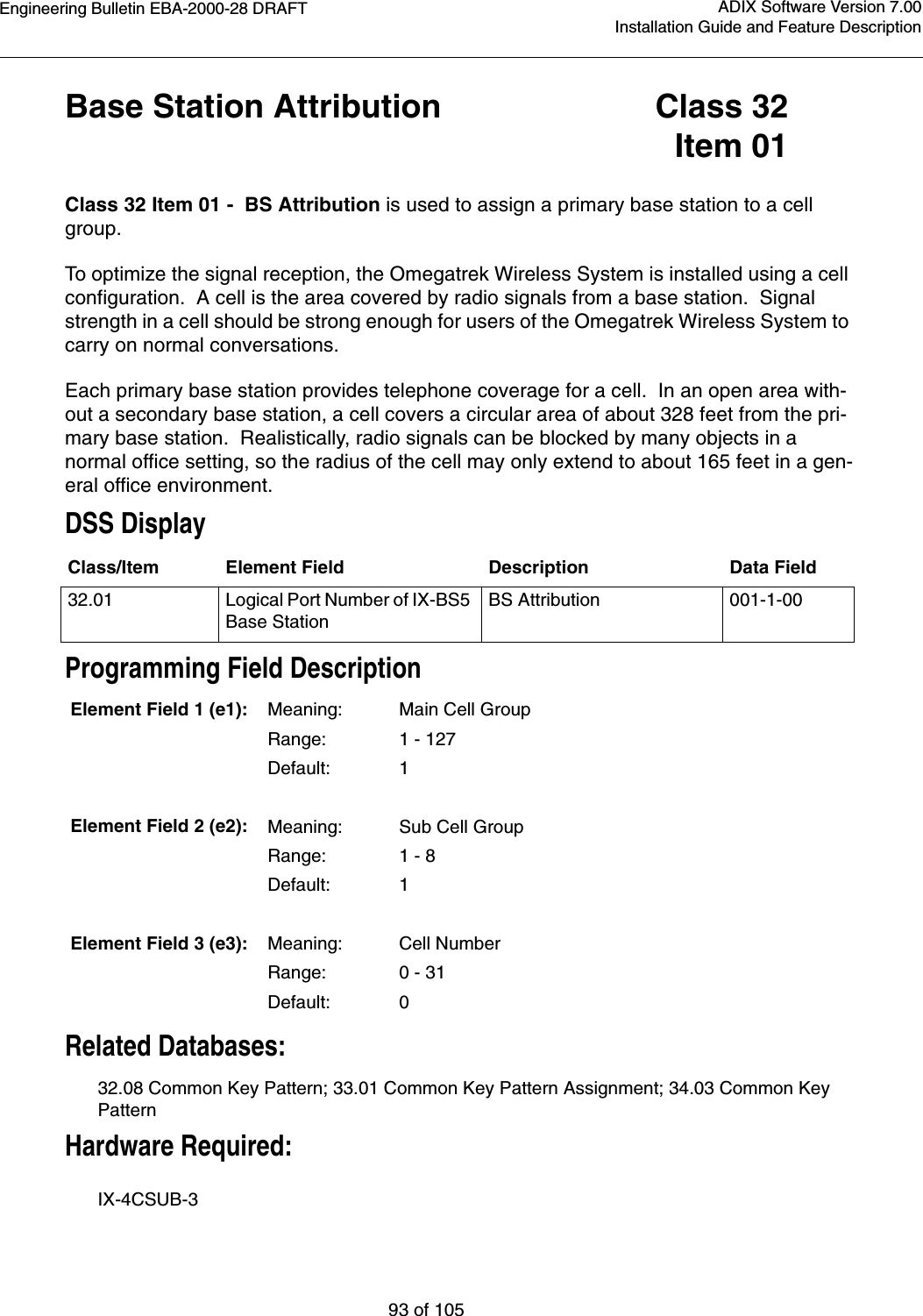
![Engineering Bulletin EBA-2000-28 DRAFT17 of 105ADIX Software Version 7.00Installation Guide and Feature DescriptionCO Outgoing Call Features•Optimized Routing. Optimized Routing is frequently referred to as either Least Cost Routing (LCR) or Automatic Route Selection (ARS). This feature allows ADIX/APS to automatically select the most inexpensive way to make an outgoing call. The system identifies the dialed number, then selects the most cost-effective outside line group. If a line in the first choice out-side line group is not available the system may be programmed to select an alternate outside line group. Stations may be programmed as Forced Optimized or assigned an Optimized Key.•CO Line Direct Access. A multipurpose button on an ADIX/APS digital telephone can be programmed as a [COL n] button for direct access to an outside line for incoming and outgoing calls. • CO Line Group Access. One or more CO lines can be assigned to a group that is used for remote CO forwarding, incoming calls, outgoing calls, or both incoming and outgoing calls. •Outside Line Call and Pick Up Restriction. The system can be programmed to restrict any phone from making outside line calls on specified outside line groups and it can be pro-grammed to restrict stations from accessing incoming calls on specific outside lines.ICM Incoming/Outgoing Features•Doorphone Call. The doorphone can be programmed for use as a simplified intercom exten-sion at a building entrance or sound monitoring locations. When the call button on the door-phone is pressed up to 16 stations programmed in Database Programming. • Hunting Call. A Hunt Group may be programmed as the delayed ringing assignment for a trunk. If a call on a CO line is not answered at the ringing stations within a programmable dura-tion, the call starts ringing to the hunt group designated. • Intercom Call. A portable station can call another station by dialing a one to four digit exten-sion number. This feature is called intercom (ICM) dialing. ICM calls can be made in either the tone or voice mode.• Tone/Voice Calling. A station user can switch the ICM calling mode from voice to tone from the station set. Database Programming is used to grant access to this feature to either the called station or the calling station.• Direct Station Selection. A multipurpose button on a portable station can be programmed as a [DSS n] button for direct access to a system extension. Direct station selection buttons pro-vide an indication if the extension programmed to that button is busy or idle. If the represented extension is busy the LED is illuminated.• Hands-Free Answerback on Intercom. This feature allows a station user to answer an inter-com call without lifting the receiver. The microphone can be turned off if desired.•Paging.•Internal Paging. An Omegatrek station can make a page announcement that is broadcast to stations that belong to a page group. •Zone (External) Paging. The ADIX/APS can be connected to an external paging system in order support four zones of paging. •Meet-Me Page Answer. A station user can answer a page from any phone that is in the same meet-me page answer group.](https://usermanual.wiki/Iwatsu-America/ADIX-BS/User-Guide-130613-Page-17.png)
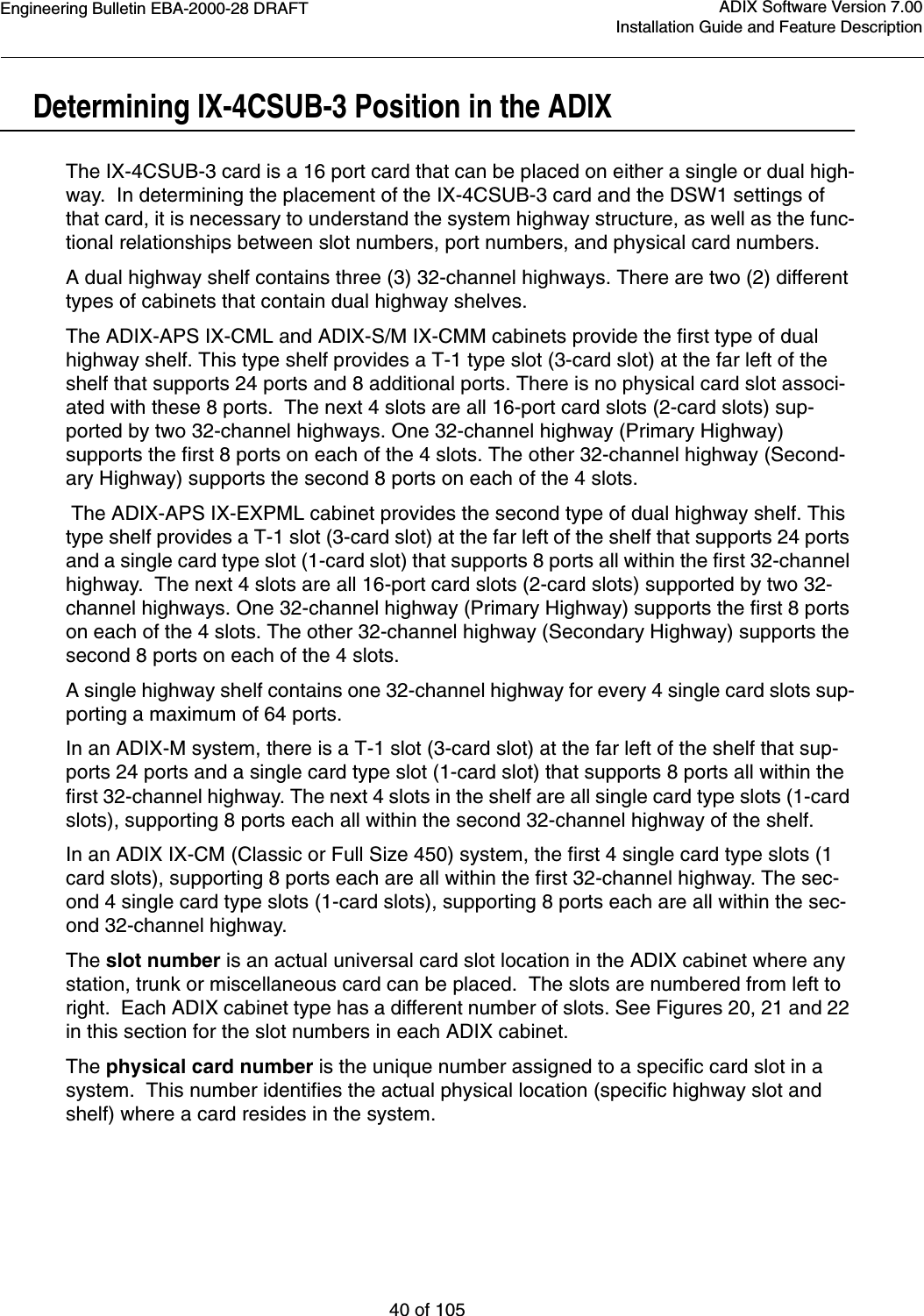
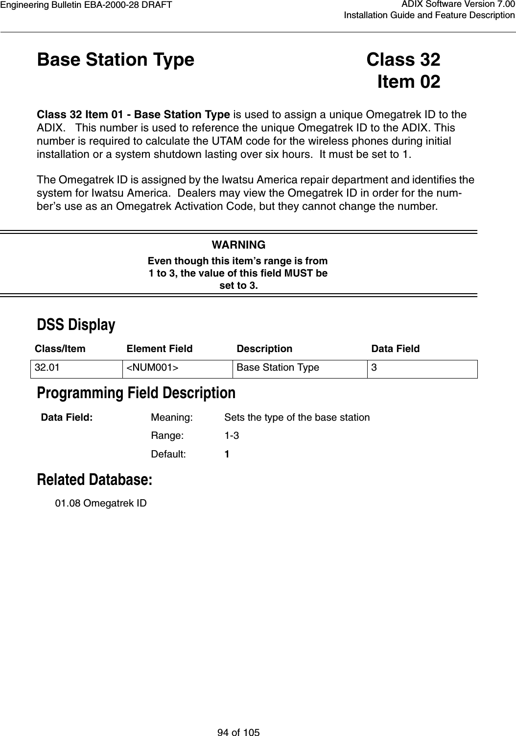
![Engineering Bulletin EBA-2000-28 DRAFT18 of 105ADIX Software Version 7.00Installation Guide and Feature DescriptionStation Features•Fixed Call Forwarding. The system database contains items that allow you to define a fixed call forward destination for each station. •Flexible Call Forwarding. This feature allows you to send your calls to an internal destina-tion or external line using Personal Speed Dial numbers 90-99. You can also separate call for-ward destinations for ICM incoming and CO incoming calls. For instance, you could set all intercom calls to go to your cell phone, and all CO calls to be forwarded to your voice mail.•Direct Outside Line Appearance. A multipurpose button on an ADIX digital telephone can be programmed as a [COL n] button for direct access to an outside line for incoming and out-going calls. A station user can also seize a specific outside line by dialing a CO line access number.•Quick-Mode Operation. This feature allows a station user to access an outside line or ICM dial tone without going off-hook.•Extension Number Display. A user can display the logical port number, extension number, and station user ID of a portable station by pressing [FEAT] + [9][9].•Message Waiting. This feature allows you to inform an extension user that there is a mes-sage waiting for them by lighting a Message Waiting Lamp on their phone. This operation allows you to send a message without having the desired extension ring.•Whisper Page. The Whisper Page feature allows portable station users to communicate with busy extensions without requiring the IX-BPAD Busy Bypass Unit. When a busy station is called using the Whisper Page feature, the busy station will hear the voice announcement via the portable station receiver. Neither the whisper page nor the busy station's response is audi-ble to the outside calling party.•Whisper Page during Consultation Hold. Whisper Page is possible during consultation hold. When a station tries to transfer a call to a busy station (placing the call on consultation hold), the station can send a whisper page to the busy station. This allows the transferring party to announce a call to a busy station and then camp-on the call all in one step.•Feature Access Using ICM Dial Codes. Feature access codes can be assigned to ICM dial codes. This allows portable station users to access system features without using the [FEAT] key. Access codes are entered on a feature-by-feature basis in the database. No default val-ues are assigned. •Single-Line Telephone Feature Access. Feature access codes can be assigned to ICM dial codes. This functionality allows SLT and data module station users to access system features without using the [FEAT] key.](https://usermanual.wiki/Iwatsu-America/ADIX-BS/User-Guide-130613-Page-18.png)
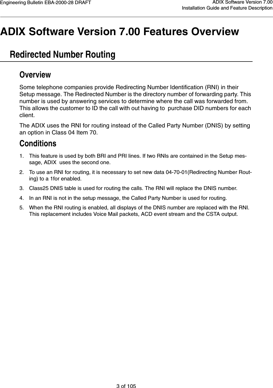
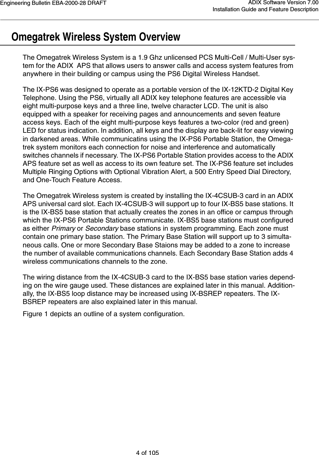
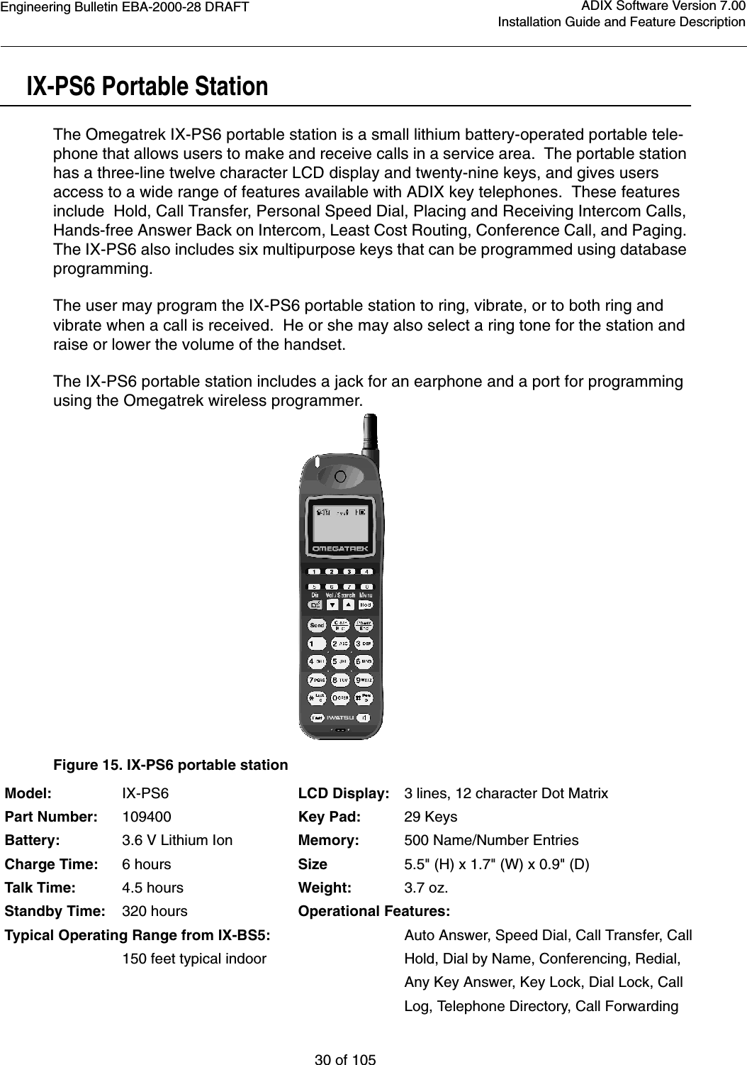
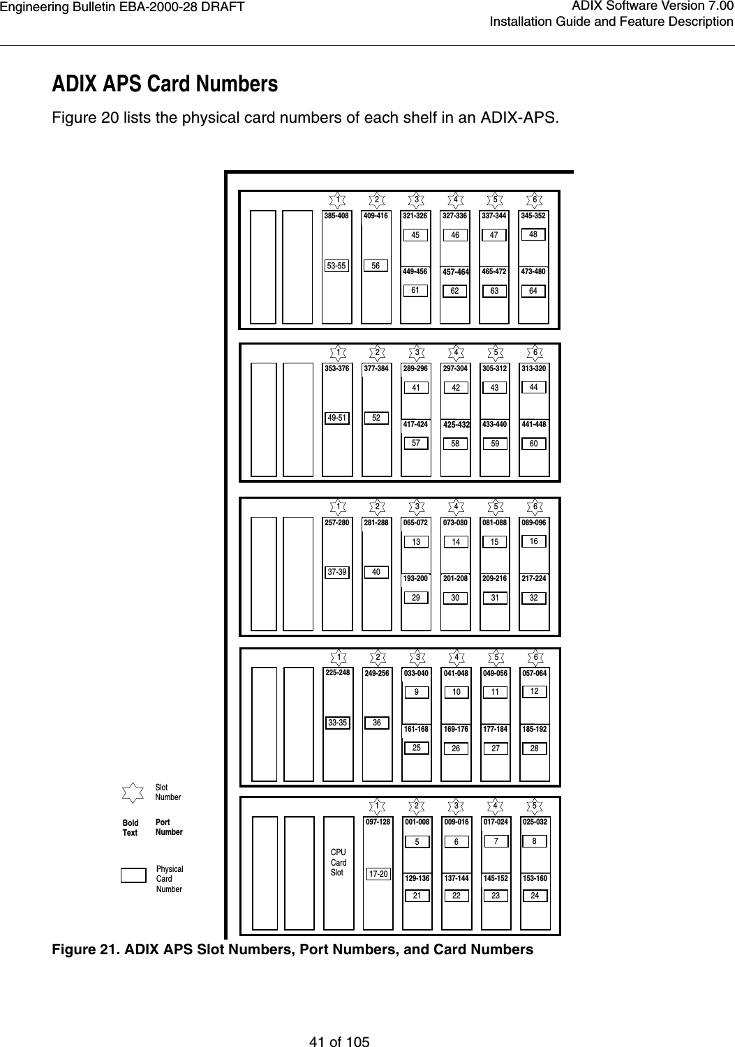
![Engineering Bulletin EBA-2000-28 DRAFT20 of 105ADIX Software Version 7.00Installation Guide and Feature DescriptionOut of AreaIf you walk outside of the service area while the phone is in the idle state, the Antenna icon on the display will disappear. If this happens, go to an area where you can see the Antenna icon again to receive or place a call.If you walk outside of the service area while you are talking on the phone, you will lose the voice of the other party or start hearing an out-of-area warning tone. If this happens, go to an area where the signal is stronger (or where you no longer hear the warning tone).Notes:You cannot talk on the phone while an out-of-area warning tone sounds.Do not place a call in the service area when you hear a busy tone and see the wordsCHANNEL BUSY on the display. Other cordless phones are using all available chan-nels, so no channels are open. Try again later.Occasionally the [SEND] key and dial pad keys may not function in the service areabecause the portable station is communicating with the base station. Try again later.Reception improves if the antenna is extended.If you walk outside of the service area while you are talking on the phone, the call maydisconnect after a warning tone sounds.Building structure may reduce the size of the service area.The Omegatrek Wireless system is created with the addition of IX-BS5 base stations, IX-PS6 portable stations and repeaters to ADIX APS systems. IX-BS5 base stations trans-mit information to and receive information from Omegatrek IX-PS6 portable stations. Omegatrek IX-PS6 portable stations are wireless digital handsets that allow users to make and receive calls and utilize many of the features included with ADIX key tele-phones. Repeaters extend the wiring distance between IX-BS5 base stations and the ADIX system.](https://usermanual.wiki/Iwatsu-America/ADIX-BS/User-Guide-130613-Page-20.png)
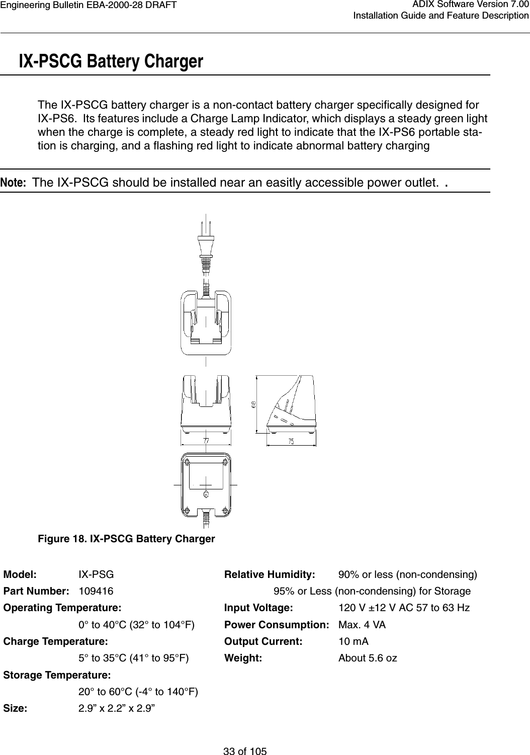
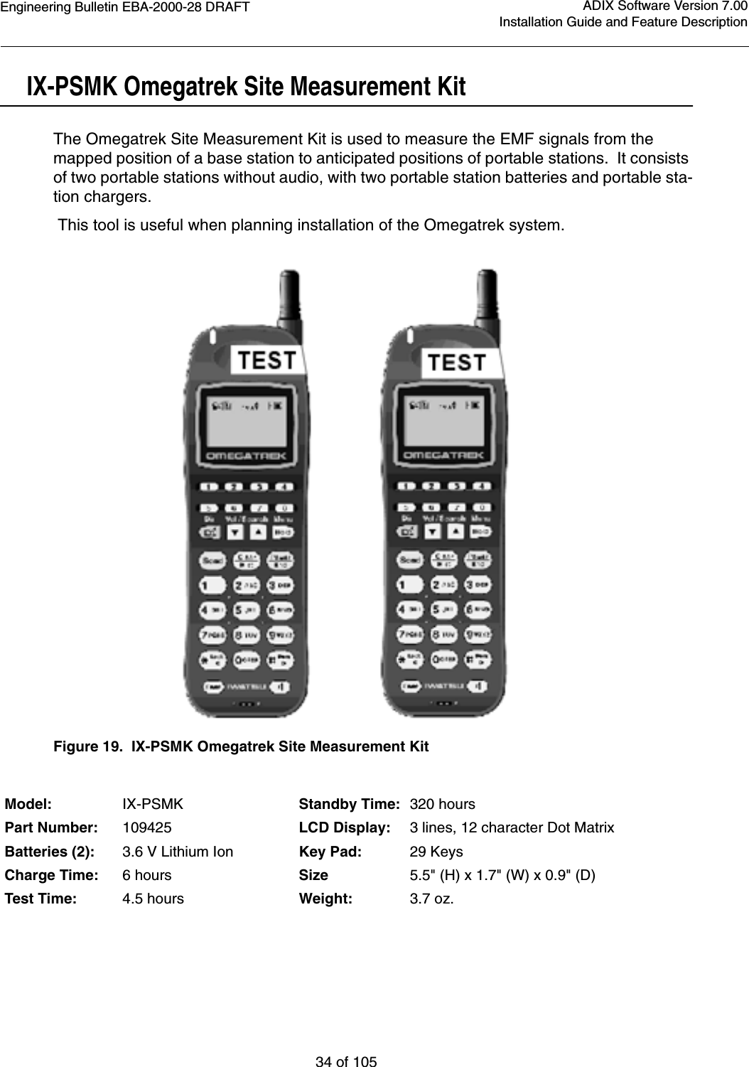
![Engineering Bulletin EBA-2000-28 DRAFT36 of 105ADIX Software Version 7.00Installation Guide and Feature DescriptionUsing the Omegatrek Site Measurement Kit for Signal CheckingBefore conducting a signal check, prepare the following for the service area in which the Omegatrek system is to be installed:•A floor plan•A survey of building conditions•A map of the desired service areaAs is often the case, cell planning on paper may not work well in an actual system instal-lation. For this reason, you should check signal conditions at the installation site before-hand.The Omegatrek Site Measurement Kit measures EMF strength from the position at which you will place the base station to various positions where you anticipate portable station positioning. This feature is very helpful during the installation process to determine loca-tions of the base stations.To use the Omegatrek Site Measurement Kit to determine the positions of base stations:1. Remove the test portable stations from the boxes, insert the batteries, and fully charge the units.2. Determine the desired locations of all base stations and probable movement areas for all associated portable stations.3. On one of the test portable stations, press [POWER] [#] [4] simultaneously. The password screen displays.4. Press [5] + [1] + [6] + [2]. The Class 1 screen displays.5. Press [2] + [HOLD] to enter Class 02. The Item screen displays.6. Press [2] + [HOLD] to enter Item 02. The Element screen displays.7. Press [1] + [HOLD]. The Omegatrek ID screen displays.8. Enter any number to serve as the Omegatrek ID. Record or remember the number that you enter at this screen. 9. Press [HOLD] after you have entered and properly recorded the Omegatrek ID. The Element 4 screen displays.10. Press [HOLD]. The Class 2, Item 2, Element 4 screen displays.11. Enter an ID number, record or remember the number, then press [HOLD]. The Write Com-pleted screen displays briefly.12. Turn the test portable station OFF.13. Follow steps 3-10 for the second portable station using a different Omegatrek ID.14. Turn both test portable stations ON.15. Use the first test portable station to call the second portable station.16. Answer the second portable station.17. Press [FEAT] + [1] on both test portable stations. The EMF strength displays.18. Place one test portable station at the location where you wish to install a base station.](https://usermanual.wiki/Iwatsu-America/ADIX-BS/User-Guide-130613-Page-36.png)
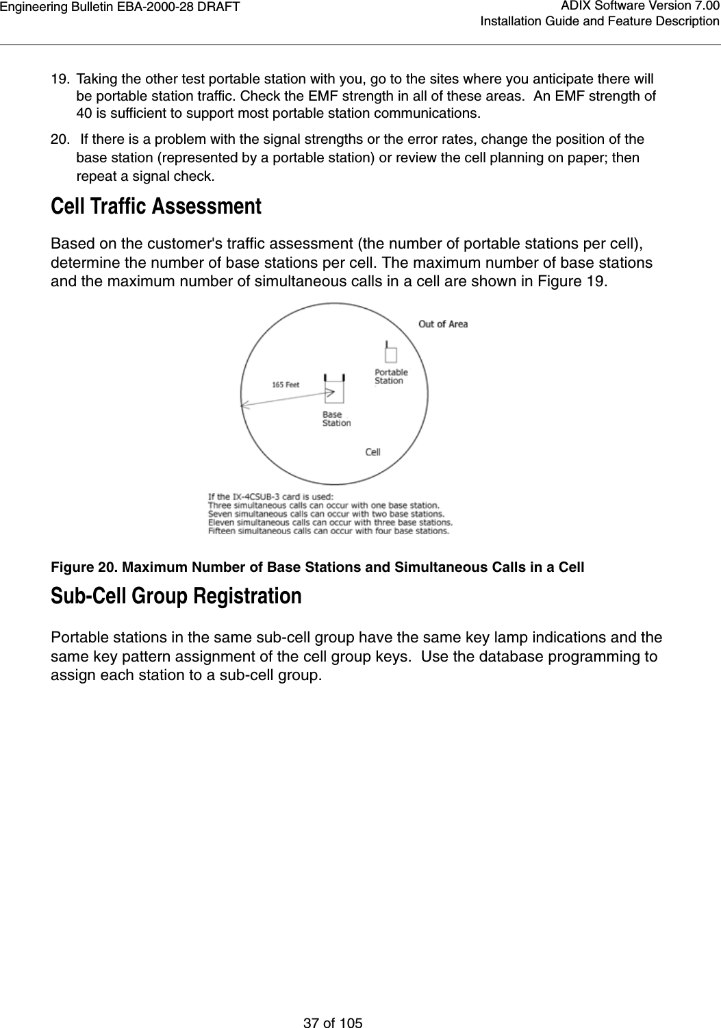
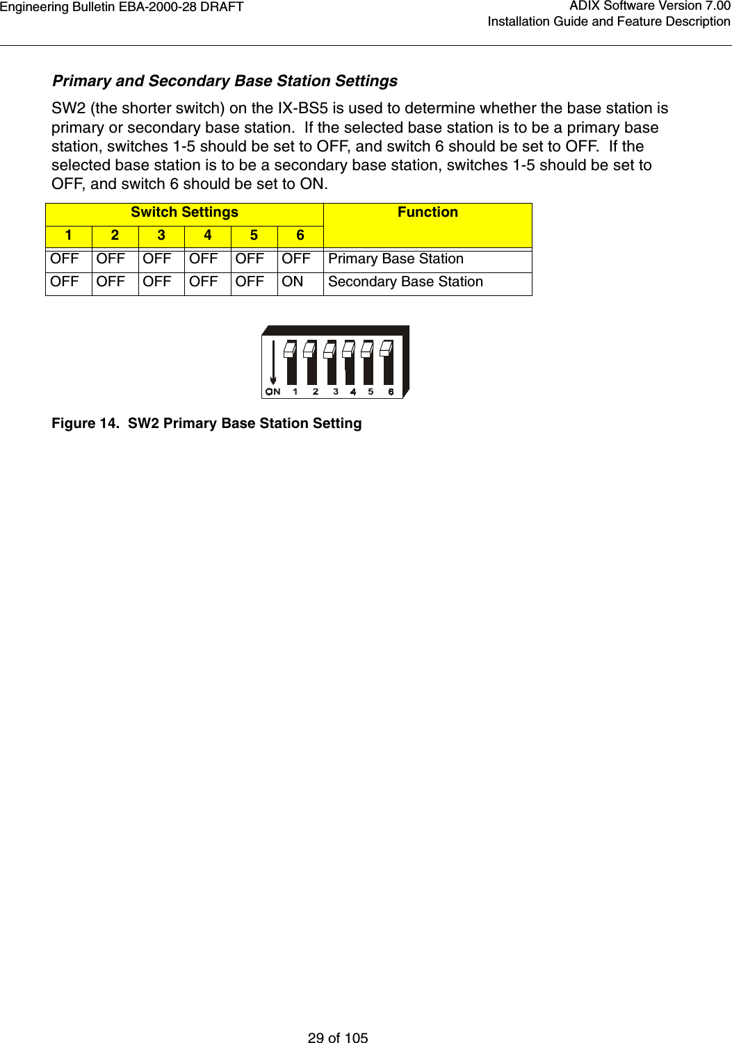
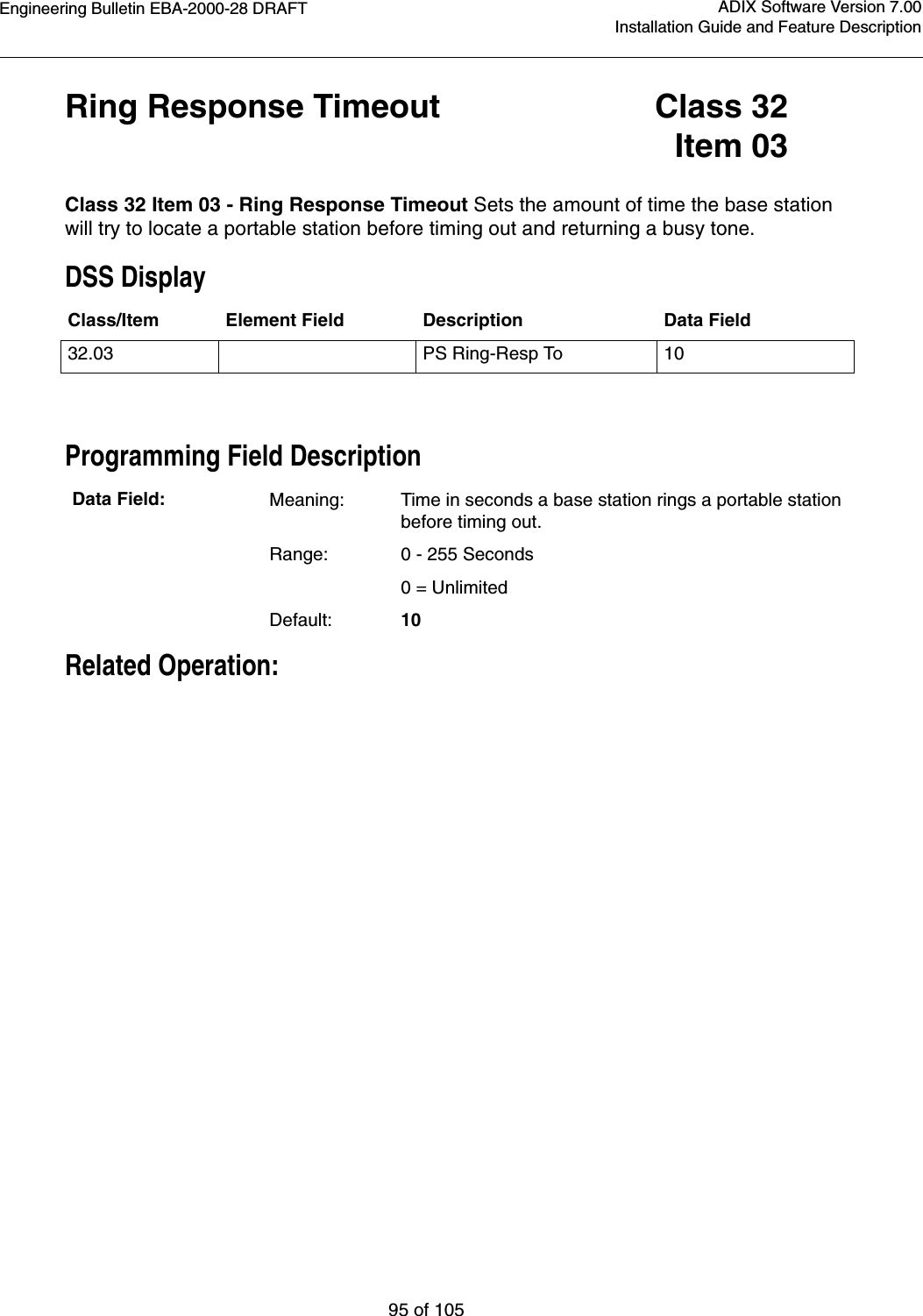
![Engineering Bulletin EBA-2000-28 DRAFT70 of 105ADIX Software Version 7.00Installation Guide and Feature Description•Up to 32 portable stations per primary base station can be in stand-by mode at one time, but that number should be kept to fewer than sixteen due to shared resources issues.•The number of portable stations with simultaneous key lamp indication changes on their indi-vidual keys should be kept to four or fewer due to system speed issues. The last portable sta-tion to have a lamp indication change is about 1.5 seconds later than the first one.•Including many cells in one main cell group is not recommended. Keep the number of primary base stations per main cell group to 10 or fewer.Notification signals may be delayed if many incoming calls are received at the same time. Configuration Procedures1. Determine the number and placement of primary base stations and secondary base stations after you have established the number of portable stations, the number of simultaneous con-versations needed, and the location of your cells. 2. Remove the plastic tabbed plate from the bottom right of the IX-BS5. See Figure 36.3. Set the base station ID switches using the SW1 and SW2 [1-5] DIP switches. Primary base stations in cells have unique primary base station IDs that are numbered from 1 to 108. 4. Set the operation mode as either primary or secondary using SW2 [6].•To make the base station a primary base station, set switch SW2 [6] to OFF. The primary setting is the default setting for this switch. Because a primary base station transmits and receives control information on the control channel, three voice channels are available. There should be one primary base station in each cell.•To make the base station a secondary base station, set switch SW2 [6] ON. Four voice channels are available for a secondary base station. Up to three base stations can be sec-ondary base stations in a cell. These secondary base stations are connected to the same IX-4CSUB-3 card to which the primary base station is connected. Figure 37. IX-BS5 Base Station Switch Settings](https://usermanual.wiki/Iwatsu-America/ADIX-BS/User-Guide-130613-Page-70.png)
![Engineering Bulletin EBA-2000-28 DRAFT73 of 105ADIX Software Version 7.00Installation Guide and Feature DescriptionIX-PS6 Portable Station ConfigurationPortable Station Installation Conditions•Up to 96 portable stations per IX-4CSUB-3 card can be in stand-by mode at once.•Up to 32 portable stations per primary base station can be in stand-by mode at once.•The number of portable stations in the stand-by mode per primary base station should be kept to 16 or fewer.•The number of portable stations with simultaneous key lamp indication changes on their indi-vidual keys should be kept to 4 or fewer. The last portable station to have a lamp indication change is about 1.5 seconds later than the first one. This restrictions on varies depending upon with whether key lamp indications change on multiple portable stations and how often changes are made. •The total number of individual keys on the portable stations in the standby mode per primary base station should be kept to 64 or fewer.Maintenance Mode Omegatrek has a maintenance mode that can display the associated base station, mea-sure the EMF strength and show frame error rate. These features are very helpful during the installation process to determine locations of the base stations.To enter the maintenance mode before you turn the portable station on, hold the [Feat] and [2] key and the press the [Power] key. When the station is on, you can use the fol-lowing features:•To measure receive level and frame error rate (FER), press [Feat] + [1]. The receive level dis-plays on the top line of the portable station’s LCD, and the frame error rate displays on the bot-tom line.•To display the carrier number and slot number, press [Feat] + [2]. The carrier number displays on the top line of the portable station’s LCD, and the slot number displays on the bottom line.•To display the cell number, press [Feat] + [3]. The cell number displays on the top line of the portable station’s LCD.•To display the main cell number, press [Feat] + [4]. The main cell number displays on the top line of the portable station’s LCD.•To display the Omegatrek ID, press [Feat] + [5]. The Omegatrek ID displays on the top line of the portable station’s LCD.](https://usermanual.wiki/Iwatsu-America/ADIX-BS/User-Guide-130613-Page-73.png)
![Engineering Bulletin EBA-2000-28 DRAFT75 of 105ADIX Software Version 7.00Installation Guide and Feature Description8. Adjust the antennas on the base stations so that they point upright. If the base station is mounted on a wall, tilt the antennas approximately 30 degrees.9. If you default a new system at this point, the system builds wight portable station ports auto-matically in the slot where the IX-4CSUB-3 card is installed.10. Set the Base Station Attributes in Class 32, Item 01, Element 1 of Database Programming. The Base Station Attribute number is the number that previously entered as the ID number through SW1 of the base station.11. Default the ADIX system. The base station’s LED should light up red. Each of the four green LEDs on the IX-4CSUB-3 card should flash quickly for each base station attached to the card.12. Register each portable station. All portable stations must be registered before they can be used. To complete portable station registration, complete the following steps:•From a Programming Telephone (SATT), press the {Idle} + [FEAT] + [#] + [1] keys. Enter Password displays on the LCD.•Enter the Password [5] + [6] + [2] + [2]. PS Programming displays on the LCD.•Enter the Programming Level, either [0] or [2]. 0 is initial data clear; 2 is data initialization.•Enter the Station Logical Number, which must be entered as 3 digits.•Enter the PS Programming Password. The Programming Password is composed of four digits ranging from 0000 to 9999, and the value is not related to any other password in an ADIX.•Press Enter.Enter PasswordPS Programming - -PS Programming 2 - -PS Programming 2 - 009 -PS Programming 2 - 001 - 1234](https://usermanual.wiki/Iwatsu-America/ADIX-BS/User-Guide-130613-Page-75.png)
![Engineering Bulletin EBA-2000-28 DRAFT76 of 105ADIX Software Version 7.00Installation Guide and Feature Description13. From the portable station being programmed, complete the following steps:•Before you can register the portable station, it must be in the programming mode. To enter programming mode, hold the [8] and [#] keys while turning the phone on. The following screen displays on the portable station’s LCD after a link is established with the program-ming base station.•When a link is not established with the programming base station, the following message displays on the portable station.•After a link has been established, the portable station displays a request for the system number.•Enter the System Number [1] - [9]. You can have up to 9 Omegatrek IDs stored in a porta-ble station. The password screen displays.•Press the [Hold/Menu] Enter Key.•Enter your password 0000-9999. This password is same password as set above in the ADIX.•Press the [Hold/Menu] Enter Key. •After programming is completed successfully, the following displays on the LCD.•If the portable station’s programming fails, the following screen displays:PROGRAMMING VX XX XXXXLINK FAILEDCOMPLETEDFAILEDH](https://usermanual.wiki/Iwatsu-America/ADIX-BS/User-Guide-130613-Page-76.png)
![Engineering Bulletin EBA-2000-28 DRAFT81 of 105ADIX Software Version 7.00Installation Guide and Feature DescriptionPortable Station Key AssignmentTo make a portable station key assignment:1. Enter programming mode by holding the [8] and [#] keys while turning the phone on. The fol-lowing screen displays on the portable station’s LCD after a link is established with the pro-gramming base station.2. Define the key patterns in both a personal station and the system.3. To make Key Assignments to the multipurpose keys, program the key patterns in Class 10.12 for each portable station. 4. Define the Key Numbers and Key Pattern Types in Class 14.01.5. Define Group Key Assignments for each Group Call Area.6. You can define a maximum of 127 All Call Areas in seven Group Call Areas created for each All Call Area.7. To make group key assignment to the flexible keys, key patterns (selected from 64 key pat-terns) must be programmed in Class 32.02 for each Group Call Area.8. Define the key numbers and types of the 64 key patterns in Class 32.01.9. When a flexible key is verified for the assigned feature ([FEAT][FEAT][#][9]), the portable sta-tion displays the name of the feature programmed in Key Assignment. If the key is not pro-grammed with a feature in Key Assignment, the portable station displays the name of the feature programmed in Group Key Assignment. If no feature is programmed to the key, the operation is canceled.10. Verify the status of the Eight Line Keys (L1-L8) with the above operation.Key Assignment Number Key Data63 One Touch Key64 Redial/Clear72 Speaker73 Shift Right74 Shift Left75 Zone76 Mute77 PB Dial78 Message Readout79 Key Display80 Alert Cancellation92 Feature93 Short Flash94 Long Flash95 Flash97 Hold/Menu98 Send Intercom99 End/PowerPROGRAMMING VX XX XXXX](https://usermanual.wiki/Iwatsu-America/ADIX-BS/User-Guide-130613-Page-81.png)
![Engineering Bulletin EBA-2000-28 DRAFT85 of 105ADIX Software Version 7.00Installation Guide and Feature DescriptionTroubleshooting the Omegatrek System (Cont’d)Problem SolutionBS1~BS4 LED on a IX-4CSUB-3 flashes slowly (The cycle is 0.5sec)Check dipswitch settings on the IX-CPUP/HW and IX-4CSUB-3 cards.BS1~BS2 LEDs indicate the status of each IX-BS5. If an IX-BS5 is not connected the LED doesn't appearConfirm that the Omegatrek ID is set. You can confirm it with several tools, including PC programmer.Confirm the number of power downs. This number is one of the factors used to generate the Omegatrek Activation code. Check this number using the PC Programmer mem-ory dump at A00CH(2byte). If this value is different from the value used to generate the Omegatrek Activation code, rec-reate the code and upload it to the system again. Reset the system.Confirm that the number of IX-BS5s connected to the sys-tem is the same as the number used to generate the Ome-gatrek Activation code. If it is not, upload the number to the system again and perform a system reset.Confirm that the IX-BS5 logical numbers are set correctly for each IX-BS5, and that none are duplicated. The number is set using the long set of dipswitches on the bottom of each IX-BS5. The numbering functions in binary code.Wireless programming doesn't work because you cannot enter the SETTING screen.Confirm that the IX-BS5 logical number has been pro-grammed in Class 32 Item 04. The default is 1.Wireless programming doesn't work because PGT or PS display the error messages.Confirm that the station logical number has been entered from PGT.Confirm that you used the same password (4 digits) between PGT and programmed portable station.Some keys on IX-PS6 (such as [Feat]) do not work.Confirm that key pattern 101 has been chosen as the pat-tern for the IX-PS6](https://usermanual.wiki/Iwatsu-America/ADIX-BS/User-Guide-130613-Page-85.png)
![Engineering Bulletin EBA-2000-28 DRAFT100 of 105ADIX Software Version 7.00Installation Guide and Feature DescriptionCommon Key Pattern Class 32Item 08Class 32 Item 08 - Common Key Pattern is used to assign a one of the common key patterns to a sub-cell group. Each portable station can use common key if the portable station is in sub-cell group set in the portable station data.Setting up a common key pattern for base stations improves system performance by lim-iting the number of individual keys in use at one time. Individual keys are keys that must have a signal sent from the base station to the personal station to function. These keys include CO[n] keys, FLOAT[n] keys, and GROUP PARK[n] keys.If you have more than 640 individual keys (80 portable stations), use this class to set up a common key pattern. If you have fewer than 640 individual keys, you may use Class 14 to set up your key patterns. DSS DisplayProgramming Field DescriptionRelated Databases:14.01 Station Flexible Key Assignment; 32.01 Base Station Attribution; 33.01 Common Key Pattern Assignment; 34.03 Common Key PatternRequired Hardware:IX-BS5, IX-PS6 Class/Item Element Field Description Data Field32.08 <NUM001-1> Comm Key Patt # 1Data Field: Meaning: Base Stations Common Key Pattern.Range: 1 - 64Default: 1](https://usermanual.wiki/Iwatsu-America/ADIX-BS/User-Guide-130613-Page-100.png)