Iwatsu America ADIX-BS UPCS Base Station User Manual EBA 2000 28 SW V 7 00 Omegatrek Tech
Iwatsu America Inc UPCS Base Station EBA 2000 28 SW V 7 00 Omegatrek Tech
Users Manual

ENGINEERING BULLETIN
Iwatsu America, Inc. has used its best effort to ensure that the information in this bulletin was accurate at the time of printing. Iwatsu America, Inc. makes
no warranty of any kind, expressed or implied, with regard to the contents of this bulletin. This information is subject to change without notice.
Iwatsu America Inc. Engineering Department FAX: 1-972-929-8919
8100 Jetstar Drive Customer Service: 1-800-866-6342
Irving, TX 75063 WEB: http://www.iwatsu.com
TEL: 1-800-955-8581 EMAIL: info@iwatsu.com
December 20, 2000EBA-2000-28 DRAFT
ADIX Software Version 7.00
Installation Guide and Feature Description
Contents:
Introduction - - - - - - - - - - - - - - - - - - - - - - - - - - - - - - - - - - - - - - - - - - - - - - - - - - - - - - - - -2
ADIX Software Version 7.00 Features Overview - - - - - - - - - - - - - - - - - - - - - - - - - - - - - -3
Redirected Number Routin
g
- - - - - - - - - - - - - - - - - - - - - - - - - - - - - - - - - - - - - - - - - - - - - - - - - - 3
Ome
g
atrek Wireless S
y
stem Overview - - - - - - - - - - - - - - - - - - - - - - - - - - - - - - - - - - - - - - - - - - 4
Ome
g
atrek Wireless S
y
stem Features Overview - - - - - - - - - - - - - - - - - - - - - - - - - - - - - - - - - - 15
Re
q
uired Components and Part Numbers - - - - - - - - - - - - - - - - - - - - - - - - - - - - - - - - - - - - - - - 21
Component Description - - - - - - - - - - - - - - - - - - - - - - - - - - - - - - - - - - - - - - - - - - - - - - -23
IX-4CSUB-3 Station Card - - - - - - - - - - - - - - - - - - - - - - - - - - - - - - - - - - - - - - - - - - - - - - - - - - - 23
IX-BS5 Base Station - - - - - - - - - - - - - - - - - - - - - - - - - - - - - - - - - - - - - - - - - - - - - - - - - - - - - -27
IX-PS6 Portable Station - - - - - - - - - - - - - - - - - - - - - - - - - - - - - - - - - - - - - - - - - - - - - - - - - - - -30
IX-BSREP Repeaters - - - - - - - - - - - - - - - - - - - - - - - - - - - - - - - - - - - - - - - - - - - - - - - - - - - - - - 31
IX-PSBP Lithium Ion Batter
y
- - - - - - - - - - - - - - - - - - - - - - - - - - - - - - - - - - - - - - - - - - - - - - - - - 32
IX-PSCG Batter
y
Char
g
er - - - - - - - - - - - - - - - - - - - - - - - - - - - - - - - - - - - - - - - - - - - - - - - - - - - 33
IX-PSMK Ome
g
atrek Site Measurement Kit - - - - - - - - - - - - - - - - - - - - - - - - - - - - - - - - - - - - - - 34
System Planning and Installation - - - - - - - - - - - - - - - - - - - - - - - - - - - - - - - - - - - - - - - -35
Cell Plannin
g
- - - - - - - - - - - - - - - - - - - - - - - - - - - - - - - - - - - - - - - - - - - - - - - - - - - - - - - - - - - - 35
S
y
stem Capacit
y
- - - - - - - - - - - - - - - - - - - - - - - - - - - - - - - - - - - - - - - - - - - - - - - - - - - - - - - - - 38
Determinin
g
IX-4CSUB-3 Position in the ADIX - - - - - - - - - - - - - - - - - - - - - - - - - - - - - - - - - - - - 40
Wirin
g
Plannin
g
- - - - - - - - - - - - - - - - - - - - - - - - - - - - - - - - - - - - - - - - - - - - - - - - - - - - - - - - - - 44
Environmental and Structural Conditions - - - - - - - - - - - - - - - - - - - - - - - - - - - - - - - - - - - - - - - - 47
Software Setup - - - - - - - - - - - - - - - - - - - - - - - - - - - - - - - - - - - - - - - - - - - - - - - - - - - - - - - - - - 48
Groundin
g
Re
q
uirements - - - - - - - - - - - - - - - - - - - - - - - - - - - - - - - - - - - - - - - - - - - - - - - - - - - 62
Confi
g
urin
g
the IX-4CSUB-3 Card - - - - - - - - - - - - - - - - - - - - - - - - - - - - - - - - - - - - - - - - - - - - - 67
Confi
g
urin
g
the IX-BS5 Base Station - - - - - - - - - - - - - - - - - - - - - - - - - - - - - - - - - - - - - - - - - - - 69
Confi
g
urin
g
the IX-BSREP Repeater - - - - - - - - - - - - - - - - - - - - - - - - - - - - - - - - - - - - - - - - - - - 71
IX-PS6 Portable Station Confi
g
uration - - - - - - - - - - - - - - - - - - - - - - - - - - - - - - - - - - - - - - - - - - 73
Ome
g
atrek S
y
stem Installation - - - - - - - - - - - - - - - - - - - - - - - - - - - - - - - - - - - - - - - - - - - - - - - 74
IX-PS6 Portable Station Batter
y
Installation - - - - - - - - - - - - - - - - - - - - - - - - - - - - - - - - - - - - - - 83
Troubleshootin
g
and Setup Verification - - - - - - - - - - - - - - - - - - - - - - - - - - - - - - - - - - - - - - - - - 84
Database Programming Guide - - - - - - - - - - - - - - - - - - - - - - - - - - - - - - - - - - - - - - - - - -87

En
g
ineerin
g
Bulletin EBA-2000-28 DRAFT
2 of 105
ADIX Software Version 7.00
Installation Guide and Feature Description
Introduction
Note:
Before you be
g
in to install and pro
g
ram ADIX Software Version 7.00, make sure to read this bulletin
for installation instructions, new features and enhancements, and other important information.
This document includes information about the followin
g
added features:
• Redirected Number Routin
g
•Ome
g
atrek Wireless System
• Features and Operations · A description of each system feature.
• Component Description and Specifications · A description of each piece of system hard-
ware.
• System Plannin
g
and Installation · Installation instructions and procedures.
This document also contains a Database Pro
g
rammin
g
Guide, which is a detailed
description of the ADIX/Ome
g
atrek pro
g
rammin
g
database.

En
g
ineerin
g
Bulletin EBA-2000-28 DRAFT
3 of 105
ADIX Software Version 7.00
Installation Guide and Feature Description
ADIX Software Version 7.00 Features Overview
Redirected Number Routing
Overview
Some telephone companies provide Redirectin
g
Number Identification (RNI) in their
Setup messa
g
e. The Redirected Number is the directory number of forwardin
g
party. This
number is used by answerin
g
services to determine where the call was forwarded from.
This allows the customer to ID the call with out havin
g
to purchase DID numbers for each
client.
The ADIX uses the RNI for routin
g
instead of the Called Party Number (DNIS) by settin
g
an option in Class 04 Item 70.
Conditions
1. This feature is used by both BRI and PRI lines. If two RNIs are contained in the Setup mes-
sa
g
e, ADIX uses the second one.
2. To use an RNI for routin
g
, it is necessary to set new data 04-70-01(Redirectin
g
Number Rout-
in
g
) to a 1for enabled.
3. Class25 DNIS table is used for routin
g
the calls. The RNI will replace the DNIS number.
4. In an RNI is not in the setup messa
g
e, the Called Party Number is used for routin
g
.
5. When the RNI routin
g
is enabled, all displays of the DNIS number are replaced with the RNI.
This replacement includes Voice Mail packets, ACD event stream and the CSTA output.

En
g
ineerin
g
Bulletin EBA-2000-28 DRAFT
4 of 105
ADIX Software Version 7.00
Installation Guide and Feature Description
Omegatrek Wireless System Overview
The Ome
g
atrek Wireless System is a 1.9 Ghz unlicensed PCS Multi-Cell / Multi-User sys-
tem for the ADIX APS that allows users to answer calls and access system features from
anywhere in their buildin
g
or campus usin
g
the PS6 Di
g
ital Wireless Handset.
The IX-PS6 was desi
g
ned to operate as a portable version of the IX-12KTD-2 Di
g
ital Key
Telephone. Usin
g
the PS6, virtually all ADIX key telephone features are accessible via
ei
g
ht multi-purpose keys and a three line, twelve character LCD. The unit is also
equipped with a speaker for receivin
g
pa
g
es and announcements and seven feature
access keys. Each of the ei
g
ht multi-purpose keys features a two-color (red and
g
reen)
LED for status indication. In addition, all keys and the display are back-lit for easy viewin
g
in darkened areas. While communicatins usin
g
the IX-PS6 Portable Station, the Ome
g
a-
trek system monitors each connection for noise and interference and automatically
switches channels if necessary. The IX-PS6 Portable Station provides access to the ADIX
APS feature set as well as access to its own feature set. The IX-PS6 feature set includes
Multiple Rin
g
in
g
Options with Optional Vibration Alert, a 500 Entry Speed Dial Directory,
and One-Touch Feature Access.
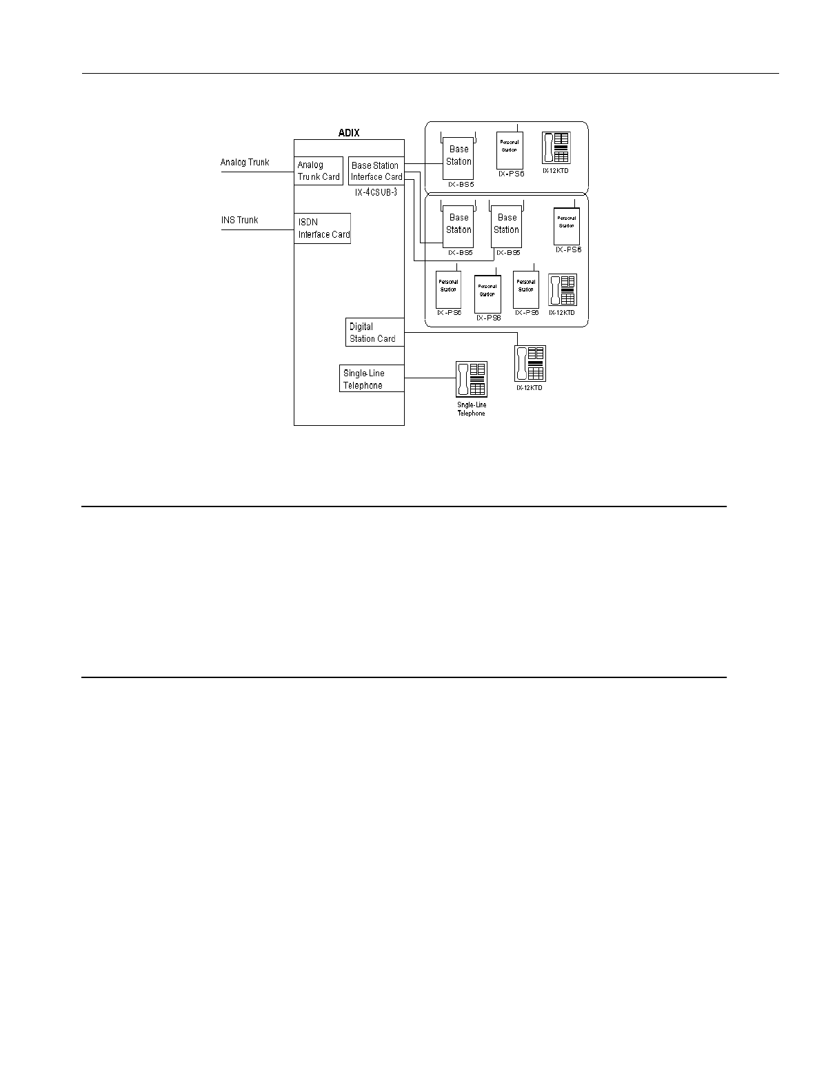
The Ome
g
atrek Wireless system is created by installin
g
the IX-4CSUB-3 card in an ADIX
APS universal card slot. Each IX-4CSUB-3 will support up to four IX-BS5 base stations. It
is the IX-BS5 base station that actually creates the zones in an office or campus throu
g
h
which the IX-PS6 Portable Stations communicate. IX-BS5 base stations must confi
g
ured
as either
Primary
or
Secondary
base stations in system pro
g
rammin
g
. Each zone must
contain one primary base station. The Primary Base Station will support up to 3 simulta-
neous calls. One or more Secondary Base Staions may be added to a zone to increase
the number of available communications channels. Each Secondary Base Station adds 4
wireless communications channels to the zone.
The wirin
g
distance from the IX-4CSUB-3 card to the IX-BS5 base station varies depend-
in
g
on the wire
g
au
g
e used. These distances are explained later in this manual. Addition-
ally, the IX-BS5 loop distance may be increased usin
g
IX-BSREP repeaters. The IX-
BSREP repeaters are also explained later in this manual.
Fi
g
ure 1 depicts an outline of a system confi
g
uration.
En
g
ineerin
g
Bulletin EBA-2000-28 DRAFT
5 of 105
ADIX Software Version 7.00
Installation Guide and Feature Description
.
Figure 1.System Configuration
Omegatrek and UTAM
NOTE FROM THE FCC
This device complies with part 15 of the FCC Rules. Operation is subject to the followin
g
two conditions: (1) This device may not cause harmful interference, and (2) this device
must accept any interference received, includin
g
interference that may cause undesired
operation.
Installation of this equipment is subject to notification and coordination with UTAM, Inc.
Any relocation of this equipment must be coordinated throu
g
h, and approved by UTAM.
UTAM may be contacted at (800) 429-UTAM.
The Iwatsu Ome
g
atrek Wireless system is desi
g
ned for use in the United States in the
Unlicensed Personal Communication Services (UPCS) 2 GHz unlicensed frequency
band. As such, Iwatsu America will be subject to the rules and re
g
ulation of UTAM (Unli-
censed Transition and Mana
g
ement of the 2 GHz Unlicensed Frequency Band). UTAM
was created to solve the unique problems facin
g
the UPCS industry. In order to deploy
unlicensed devices and systems that are by nature easily portable, microwave licensees
currently operatin
g
in the 2 GHz Unlicensed Frequency Band must be relocated to other
frequencies because of the potential for interference to their microwave operations from
unlicensed devices. Since the spectrum is unlicensed, however, no one manufacturer has
an incentive to relocate the microwave links because all manufacturers have equal ri
g
hts
to the cleared spectrum. While band clearin
g
will undoubtedly be a time-consumin
g
pro-
cess, demand for UPCS exists now. To meet this demand and to provide a revenue
stream to fund the clearin
g
process, the industry proposed permittin
g
limited, coordinated
deployment of qualifyin
g
UPCS systems and devices in a manner that would avoid inter-
ference to incumbent microwave systems.

En
g
ineerin
g
Bulletin EBA-2000-28 DRAFT
6 of 105
ADIX Software Version 7.00
Installation Guide and Feature Description
The Ome
g
atrek Wireless System cannot transmit in the 2 GHz Unlicensed Frequency
Band without authorization from UTAM. Iwatsu will process all UTAM information, keep-
in
g
distributor involvement to a minimum. When a distributor provides Iwatsu with the
necessary application information for UTAM, includin
g
the locations and number of base
stations that will be installed, Iwatsu will submit the application with UTAM. Iwatsu will
create an Activation Code once authorization from UTAM has been
g
ranted. The distrib-
utor will activate the base stations at the user’s site by enterin
g
the Activation Code.
Detailed information on UTAM may be found in the Ome
g
atrek Policy and Procedure
Manual. This document may be downloaded from the Iwatsu Distributor Access Area
Web Site www.iwatsu.com/UTAM.
Voice Channels and Control Channels
In the Ome
g
atrek Wireless System, each primary base station carries one control chan-
nel and three voice channels. Every cell must contain one primary base station. Control
channels run from the IX-4CSUB-3 card in the ADIX APS and are used for notification of
incomin
g
calls and other si
g
nal information. Voice channels carry voice and data trans-
missions.
Secondary base stations can use all four channels for transmittin
g
and receivin
g
voice
si
g
nals, so the number of channels in a cell are increased by addin
g
secondary base sta-
tions to a primary base station.
Base stations can use up to twenty-four radio channels to communicate with portable sta-
tions. The Ome
g
atrek Wireless System is equipped to switch the channel from one of the
twenty-four channels to another of the twenty-four if a portable station is usin
g
a channel
that contains noise or is affected by interference.

En
g
ineerin
g
Bulletin EBA-2000-28 DRAFT
7 of 105
ADIX Software Version 7.00
Installation Guide and Feature Description
Cells and Areas
To optimize the si
g
nal reception, the Ome
g
atrek Wireless System is installed usin
g
a cell
confi
g
uration. A cell is the area covered by radio si
g
nals from a base station. Si
g
nal
stren
g
th in a cell should be stron
g
enou
g
h for users of the Ome
g
atrek Wireless System to
carry on normal conversations.
In an open area, a cell covers a circular area of about 300 feet from a base station. Real-
istically, radio si
g
nals can be blocked by many objects in a normal office settin
g
, so the
radius of the cell may only extend to about 150 feet in a
g
eneral office environment. At a
lower readin
g
than 40 EM, users may experience the results of lower si
g
nal stren
g
th.
In the Ome
g
atrek Wireless System, as many as three calls are allowed simultaneously in
a cell with just a primary base station. The number of calls allowed can be increased by
addin
g
secondary base stations to a primary base station.
Figure 2. Model of Cell
Lar
g
er areas can be covered by combinin
g
cells. Multiple cells are
g
enerally confi
g
ured
so that users can use the Ome
g
atrek Wireless System in any area of an office or an
entire buildin
g
area. The number of cells is
g
enerally the same as the number of primary
base stations needed. However, if secondary base stations are added to increase the
number of voice channels available, the number of cells allowed decreases.
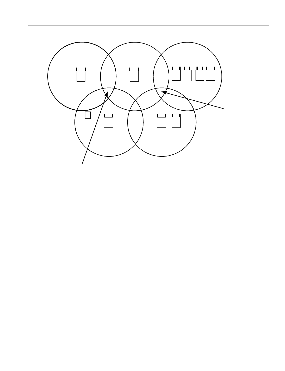
Cells may overlap and provide a hi
g
her number of channels in small areas. The maxi-
mum number of channels that transmit in an overlap area are 17. See Fi
g
ure 3 for a
detailed illustration.
Be sure to select a proper system size to provide a service area that meets your custom-
ers’ needs. Iwatsu’s IX-PSMK Site Measurement Kit (PN 109425) is desi
g
ned to simply
the process of confi
g
uratin
g
base stations durin
g
the Ome
g
atrek installation process. The
IX-PSMK Site Measurement Kit is described later in this bulletin.
Base Station
Portable Station
Cell
150 ft.
Out of Area
40 EMF
En
g
ineerin
g
Bulletin EBA-2000-28 DRAFT
8 of 105
ADIX Software Version 7.00
Installation Guide and Feature Description
Figure 3. Cells, Channel Availability, and Service Areas
A
g
roup notification area consists of one or more cells. Two, four, or ei
g
ht cells can be
defined in one simultaneous notification area. The number of cells in one simultaneous
notification area is specified in pro
g
rammin
g
of the portable stations and in the system
database.
The position of a portable station is re
g
istered to a simultaneous notification area. When
the portable station receives a call, the base stations in the simultaneous notification area
notify the portable station at the same time. When the user travels from one simulta-
neous notification area to another, the position of the portable station is automatically re
g
-
istered in the new area.
Base Stations
Base stations can be confi
g
ured as either primary base stations or secondary base sta-
tions. A primary base station transmits and receives a control channel that notifies porta-
ble stations of incomin
g
calls in addition to its three voice channels. Each cell contains
one control channel, so each cell must have a primary base station. Secondary base sta-
tions do not use control channels; they are
g
enerally used to add to the number of voice
channels that a primary base station can handle.
Outgoing and Incoming Call Control
A speech path is established in accordance with an out
g
oin
g
call request from a portable
station and in accordance with an incomin
g
call request from the ADIX/APS. Base sta-
tions controls connections and disconnections of speech paths.
Out of Area
2
Base Station
Cell 1 Cell
Base Station
Cell 3
Base Stations
Base Stations
Cell 5
Personal
Station Base Station
Cell 4
3
Channels 3
Channels
3
Channels
15
Channels
6
Chan-
nels
17
Chan-
nels
6 Chan-
nels
10
Chan-
nels
10
Chan-
nels
17 Chan-
nels
6 Chan-
nels
7
Channels
9 Channels
17
Channels
En
g
ineerin
g
Bulletin EBA-2000-28 DRAFT
9 of 105
ADIX Software Version 7.00
Installation Guide and Feature Description
Automatic Cell Handoff
As a user travels from one cell to another, the portable station automatically switches to
the nearest available cell. The user can make and receive calls in a new location and con-
tinue speakin
g
while movin
g
. The portable station automatically switches to a new voice
channel to avoid interference from other di
g
ital cordless systems or noise from other
sources.
Security Against Eavesdropping
The Ome
g
atrek provides hi
g
h security for conversations by scramblin
g
216 one key code
combinations. A key code can be set in advance or for each call, and scramblin
g
does
not de
g
rade speech quality. Ome
g
atrek also provides Access Authentication and Voice
Encryption.
Operation Status Indication
Both base stations and portable stations indicate their operation status with lamps. Por-
table stations also use backli
g
ht flashin
g
patterns and color to indicate status. The follow-
in
g
table includes information about the operation status of portable stations:.
Diversity
A base station is equipped with two antennae. The antenna with the hi
g
her sensitivity of
the two is automatically selected in order the reduce the effect of phasin
g
.
Type Light Pattern Status
Line Keys
(Backli
g
ht)
Two Quick Blinks While ON (Green) Your portable station is in use.
ON (Red) Another portable station in the
g
roup is in use.
Flashin
g
(Red) Your portable station is receivin
g
a call.
Slow Flashin
g
(Red) A call is on hold on another extension.
Slow Flashin
g
(Green) A call is on hold on your extension.
Dial Pad
(Backli
g
ht)
ON (Green) You are operatin
g
the dial pad keys.
Incomin
g
Call/
Char
g
e
Lamp
ON (Green) The battery is almost fully char
g
ed.
ON (Red) The battery is bein
g
rechar
g
ed.
Slow Flashin
g
(Red) Your battery cannot be rechar
g
ed.
Flashin
g
(Red) Your portable station is receivin
g
a call.

En
g
ineerin
g
Bulletin EBA-2000-28 DRAFT
10 of 105
ADIX Software Version 7.00
Installation Guide and Feature Description
Portable Stations
The Ome
g
atrek Portable Station is a small lithium battery-operated portable telephone
that allows users to make and receive calls in a service area. The portable station has a
three-line twelve character LCD display and twenty-nine keys, and
g
ives users access to
a wide ran
g
e of features available with ADIX key telephones includin
g
:
•Auto Answer
•Speed Dial
•Call Transfer
•Call Hold
•Dial by Name
•Conferencin
g
•Redial
•Any Key Answer
•Key Lock
•Dial Lock
•Call Lo
g
•Telephone Directory
•Call Forwardin
g

En
g
ineerin
g
Bulletin EBA-2000-28 DRAFT
11 of 105
ADIX Software Version 7.00
Installation Guide and Feature Description
Identification Numbers
The Ome
g
atrek system uses several identification numbers and call si
g
ns to authenticate
the connection between the portable stations and the base station and establish main cell
g
roups and sub-cell
g
roups. These identification numbers can be found on the IX-PS6 or
IX-BS5 hardware, or provided by Iwatsu America. The identification numbers include:
System Call Sign and Portable Station Call Sign. In the Ome
g
atrek, the system and porta-
ble stations all have different IDs. Each portable station is assi
g
ned to a unique portable sta-
tion Call Si
g
n (PS ID). One Ome
g
atrek ID, which is shared by all base stations in the system,
is assi
g
ned to each system. Base stations and portable stations are assi
g
ned authorized IDs
before shippin
g
.
In order to function properly, a system must reco
g
nize each PS ID, and the each portable sta-
tion must reco
g
nize the Ome
g
atrek ID.
Each portable station can be pro
g
rammed with up to nine system call si
g
ns, makin
g
the porta-
ble station usable in nine systems.
WARNING
Misuse of IDs and use of unautho-
rized IDs are crimes punishable by
Federal and State law. Never misuse
a PS ID or Omegatrek ID under any
circumstances.
Portable Station Number. A portable station number provides another way for the system to
reco
g
nize portable stations. The portable station’s lo
g
ical number is used as its portable sta-
tion number and is unique to the system.
CS ID and BS Logical Number. A CS ID identifies a base station and consists of a system
call si
g
n and an additional identification information includin
g
the main cell
g
roup number, a
sub-cell
g
roup number, and a BS lo
g
ical number. These identifications numbers are pro-
g
rammed in the database for each base station. Each base station is also identified by a BS
lo
g
ical number, which is confi
g
ured usin
g
the switch on the base station.
Sub-Cell Group Number. The Sub-Cell Group Number identifies an area in which the cell
g
roup key lamps on portable stations function.
Main Cell Group Number. The Main Cell Group Number identifies main cell
g
roups.

En
g
ineerin
g
Bulletin EBA-2000-28 DRAFT
12 of 105
ADIX Software Version 7.00
Installation Guide and Feature Description
Base Station - Portable Station Synchronization
When a portable station is turned on, it hunts for and synchronizes to a control channel
that meets the proper conditions for receivin
g
si
g
nal level, system call si
g
n, etc.). Once a
control channel is selected, the portable station
g
oes into standby mode. If a control
channel cannot be selected, the portable station continues huntin
g
. If a control channel
cannot be selected after a certain period, the portable station is considered to be outside
the area.
A portable station in the standby mode receives only incomin
g
call information from the
base stations. In the In-House mode, it also receives key lamp information.
Portable Station Position Notification
Because portable stations are notified of incomin
g
calls by all the base stations in their
main cell
g
roup, the ADIX/APS system needs to know which main cell
g
roup contains
each portable station portable station.
Usin
g
position re
g
istration, the portable station notifies the ADIX/APS of its current posi-
tion. A portable station performs a position re
g
istration when it is powered up, when the
user travels to another main cell
g
roup, when the user comes back in from outside the
area, or when it successfully synchronizes with a control channel from a base station.
The portable station also performs a BS position re
g
istration when the user travels
between cells. This function allows the ADIX/APS system to keep key lamp information
and LCD information for each base station, allowin
g
seamless service for portable station
users.
Channel Switchover
The system automatically switches the voice channel when a call is affected by interfer-
ence or when the user travels between cells durin
g
a call. There are two types of channel
switchover that are caused by noise and interference, TCH Channel Switchover and Cell
Switchover.
TCH Channel Switchover occurs when the portable station is switched to a different chan-
nel of the same base station. The ADIX/APS system monitors errors in order to automat-
ically switch the voice channel in case a call is affected by interference or noise.
Cell Switchover occurs when the portable station re-synchronizes with and reconnects to
a channel on the nearest base station. The ADIX/APS system monitors errors and the
received si
g
nal level and automatically switches voice channels when the user travels
between cells durin
g
a call. A cell switchover is often called a handover.

En
g
ineerin
g
Bulletin EBA-2000-28 DRAFT
13 of 105
ADIX Software Version 7.00
Installation Guide and Feature Description
Key Lamp Indications
The line status and function of the portable station are indicated when the backli
g
ht colors
of the flexible keys blink and chan
g
e. The functionality of the keys is set usin
g
ADIX/APS
Database Pro
g
rammin
g
. The portable station’s keys can be pro
g
rammed with both Cell
Group Key Attributes and Individual Key Attributes.
Cell Group Key Attributes are effective only when the portable station is inside its sub-cell
g
roup. Individual Key Attributes are effective in the whole Ome
g
atrek system, re
g
ardless
of whether the portable station is inside its sub-cell
g
roup or not.
Thou
g
h the area in which the cell
g
roup keys can be used is limited, cell
g
roup keys are
not functionally limited. Individual keys can be used re
g
ardless of area, but their functions
may be limited by traffic.
Whether a key operates as a cell
g
roup key or an individual key is determined by the key
status. There are two types of key statuses, Cell Group Key status and Individual Key sta-
tus. If the key is set as a Cell Group Key, it is normally in the Cell Group Key status. How-
ever, when a
g
reen lamp indicatin
g
I-use is illuminated, the key is temporarily in Individual
Key status. If the key attribute is set as an Individual Key, it is always in the Individual Key
status.
If a portable station in the standby mode is outside its sub-cell
g
roup, the
g
roup indication
lamps and keys are ineffective. When the portable station’s
g
reen lamp flashes indicatin
g
I-use, however, the lamps and keys are effective re
g
ardless of the portable station’s pres-
ence in its own cell
g
roup.
Even if a portable station is outside its sub-cell
g
roup, the user can still receive a direct
call on a line key with the Cell Group Key attribute. When the user answers the call, the
key
g
oes into Individual Key status and the lamps are effective.
If the portable station is in standby mode and no key is pressed for 30 seconds, the key
lamps shut off. Shutoff timin
g
may be chan
g
ed usin
g
the portable station. The key lamps
re-li
g
ht when an incomin
g
call is received or a key is pressed.
The key lamps continue workin
g
while the portable station is char
g
in
g
its battery.
En
g
ineerin
g
Bulletin EBA-2000-28 DRAFT
14 of 105
ADIX Software Version 7.00
Installation Guide and Feature Description
Sub-Cell Group
Sub-cell
g
roup consists of one or more cells. Two, four, or ei
g
ht cells can be defined in
one main cell
g
roup. The number of cells in one main cell
g
roup is specified in while pro-
g
rammin
g
the portable stations and ADIX Database Pro
g
rammin
g
.
In a sub-cell
g
roup, the portable stations’ cell
g
roup key lamps are controlled by the
g
roup. Each portable station belon
g
s to a sub-cell
g
roup.
Flexible keys operate under the followin
g
g
uidelines when the user travels out of his or
her sub-cell
g
roup or into his or her own sub-cell
g
roup
.
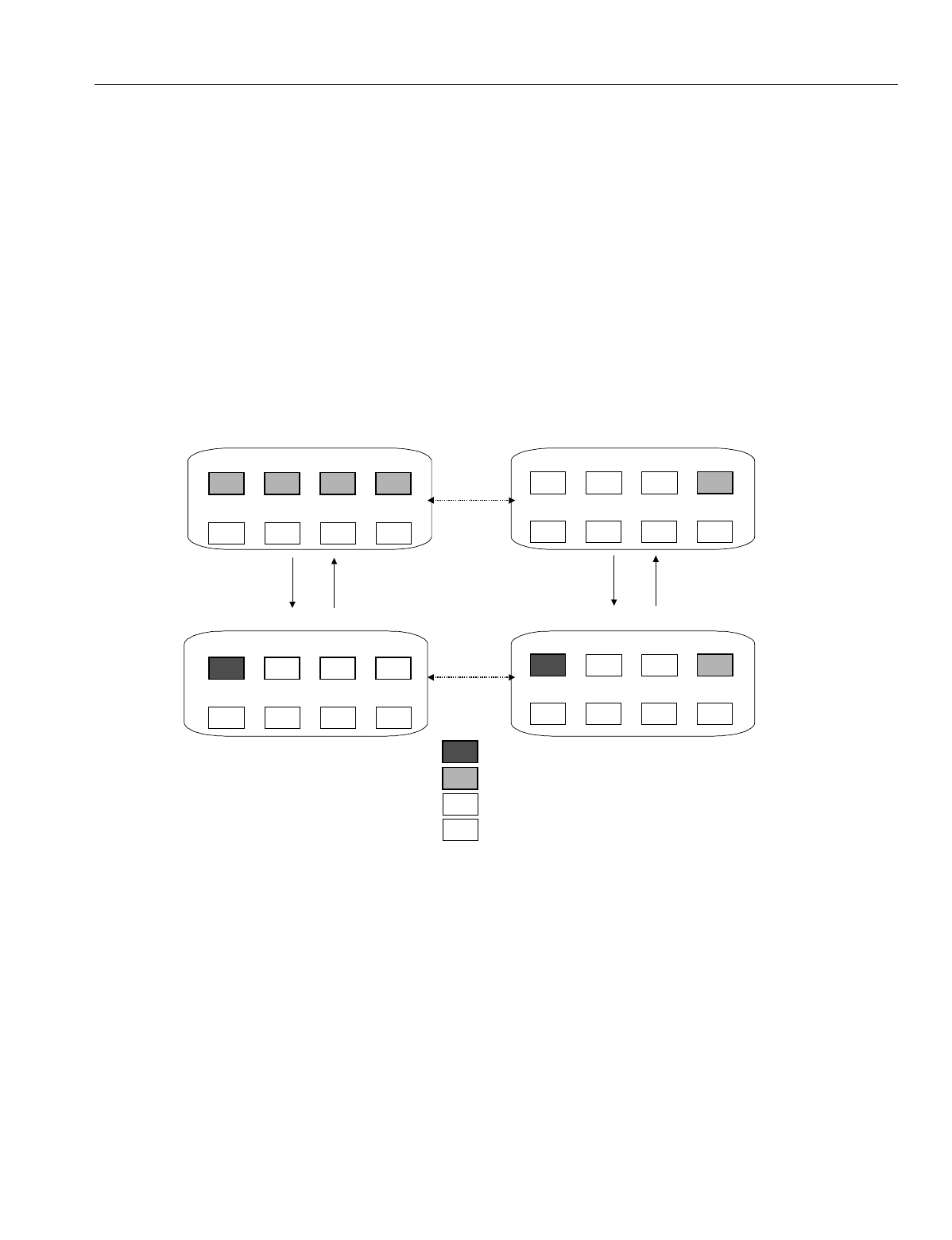
Figure 4. Portable Station key changes in a sub-cell group
F4F3F2F1
MSGPARK 2PARK 1FLT
F8F7F6F5
REDIALFLASHFWDSPEED
Portable Station Inside Its Sub-Cell Group
Standby Mode
Originating or
Receiving
(F1 key is
pressed.)
Call
Termination
During a Call
F4F3F2F1
MSGPARK 2PARK 1FLT
F8F7F6F5
REDIALFLASHFWDSPEED
F4
F3F2F1
MSGPARK 2PARK 1FLT
F8F7F6F5
REDIALFLASHFWDSPEED
Portable Station Outside Its Sub-Cell Group
Standby Mode
Originating or
Receiving
Call
Termination
During a Call
F4
F3F2
F1
MSGPARK 2PARK 1FLT
F8F7F6F5
REDIALFLASHFWDSPEED
The user
travels
while the
Portable
Station is
in the
Standby
Mode
The user
travels during
a call.
The I-use lamp is ON. The key works.
The lamp and the key are ON.
The lamp does not work. The key is ON
The lamp and the key are OFF.

En
g
ineerin
g
Bulletin EBA-2000-28 DRAFT
15 of 105
ADIX Software Version 7.00
Installation Guide and Feature Description
Omegatrek Wireless System Features Overview
CO Incoming Call Features
•Automatic Number Identification (ANI). Ome
g
atrek supports ANI trunks provided by the
phone company on T1 lines.
•Caller ID Routing. Caller ID numbers may be assi
g
ned a 16-character alphanumeric ID to
identify the callin
g
party, callin
g
party's telephone number, type of call, or purpose of call. The
Caller ID alphanumeric ID is displayed on the station LCD when a call is received on a Caller
ID trunk. A call can be routed to a station, master hunt
g
roup, or voice mailbox accordin
g
to
the Caller ID information received.
•Caller ID, ANI/DNIS, ISDN Name and Number Display. When a call is received on a caller
ID or ANI line, the Ome
g
atrek captures and stores information about the caller received with
the call in the system memory. This information includes the caller's telephone number and
name, date and time of the call, trunk number, and destination station.
•Delayed Ringing. This feature allows outside lines rin
g
in
g
at a telephone to rin
g
at another
telephone or
g
roup of telephones after a predetermined period of time.
•Dialed Number Identification Service (DNIS) Routing. DNIS (Dialed Number Identification
Service) numbers may be assi
g
ned a 16-character alphanumeric ID to identify the number the
callin
g
party dialed to reach the Ome
g
atrek. The DNIS alphanumeric ID is displayed on the
station LCD when a call is received on an DNIS trunk. A call can be routed to a station, master
hunt
g
roup, or voice mailbox accordin
g
to the DNIS information received.
•DID (Direct Inward Dialing) Alphanumeric ID Display. DID (Direct Inward Dial) numbers
may be assi
g
ned a 16-character alphanumeric ID to identify the party bein
g
called, type of call,
or purpose of call.
•Direct Inward Dial (DID) Trunks. Ome
g
atrek supports DID trunks provided by the phone
company. This service allows any number of telephones to be called directly from the outside
without the need of havin
g
a dedicated outside line for every telephone.
•Direct Inward Line (DIL). Each outside line can be assi
g
ned to rin
g
at up to 32 extensions. A
different rin
g
in
g
assi
g
nment can be pro
g
rammed for Day and Ni
g
ht modes. A rin
g
in
g
tone for
each line can be selected from four available rin
g
in
g
tones. If a delayed rin
g
in
g
assi
g
nment is
pro
g
rammed for the line, the rin
g
in
g
chan
g
es to an incomin
g
alarm when delayed rin
g
in
g
be
g
ins.
•Uniform Call Distribution (UCD). This feature allows telephone lines to be directed to a
g
roup of phones. If all phones are busy, the caller may hear a recorded messa
g
e. Calls to the
UCD
g
roup may search for an idle extension in either a Terminal or Distributed Huntin
g
pat-
tern. In Terminal Huntin
g
the incomin
g
calls always start huntin
g
from the first telephone in the
g
roup. In Distributed Huntin
g
the incomin
g
calls start huntin
g
from the telephone followin
g
the
last called telephone. In both cases, calls will hunt to the next telephone if a telephone does
not answer in a predefined period of time, is busy, or in the Call Forward, Absence Messa
g
e,
or Do Not Disturb mode. Two levels of recordin
g
are available. This allows you to play a sec-
ond messa
g
e to inform callers that you are still waitin
g
to assist them. Ome
g
atrek also has
the ability to send unanswered calls to an overflow or secondary answerin
g
position after a
predefined period of time. This second answerin
g
position may be another UCD
g
roup, hunt
g
roup, extension, or attendant.

En
g
ineerin
g
Bulletin EBA-2000-28 DRAFT
16 of 105
ADIX Software Version 7.00
Installation Guide and Feature Description
•Universal Night Answer (UNA). This feature allows you to answer calls that have been
switched to rin
g
at the Ni
g
ht Mode location.
•Direct Inward System Access (DISA). Direct Inward System Access (DISA) allows an exter-
nal caller to access Ome
g
atrek intercom dial tone by dialin
g
the phone number of an outside
line that is dedicated for DISA. DISA
g
ives the external caller the ability to make intercom,
hunt
g
roup, and external calls, and also have access to the pa
g
in
g
system. Use of DISA for
external calls and pa
g
in
g
requires the entry of a security code to control fraudulent use.
•Off-Hook Outside Line Answering. This feature allows a station user to answer an outside
call without havin
g
to press the button representin
g
the rin
g
in
g
line. The station user can still
access other system features usin
g
CO/ICM line selection while an incomin
g
call is rin
g
in
g
.
• Manual Outside Line Answering. This feature allows a station user to answer an outside
call by pressin
g
the button representin
g
the rin
g
in
g
line.
Hold/Transfer/Conference Features
•Conference. Ome
g
atrek allows you to converse with three other people in one conversation.
There may be any combination of inside extensions or outside lines.
• Hold/Hold Recall. A call can be put on hold by pressin
g
the [HOLD/DND] button. Calls that
remain on hold for a pro
g
rammable amount of time recall. The rin
g
in
g
tone for recall differs
from the rin
g
in
g
tone of an incomin
g
call. Recalls that are not picked up are automatically for-
warded to the attendant.
•Call Park/Swap and Call Park Pick-Up. Call Park/Swap allows you to alternate between two
conversations. Call Park Pick-Up allows you to answer a call rin
g
in
g
at someone else's
phone.
• Group Park. When a station places a call on
g
roup park, a station's [Group Park] button rep-
resentin
g
that
g
roup will flash red. A station can pick up the call by pressin
g
[Group Park]. If
the call is not picked up within the duration pro
g
rammed, the station that ori
g
inally placed the
call on
g
roup park is recalled.
•Transfer to Park (Call Park at Another Extension). The Ome
g
atrek system allows you to
place a call on park at another user’s extension from your portable station.
•Call Transfer. There are two ways a station user can transfer a call:
•Screened Transfer.
The call is transferred after the transferrin
g
station announces the
call.
•Unscreened Transfer.
The call is transferred without bein
g
announced.
•Accessing Guest Mailbox. This feature accommodates the Guest Mailbox feature provided
by many voice mail systems. It allows access to mailboxes that are not associated with spe-
cific ADIX extensions. The
g
uest mailbox may be accessed from any system extension.

En
g
ineerin
g
Bulletin EBA-2000-28 DRAFT
17 of 105
ADIX Software Version 7.00
Installation Guide and Feature Description
CO Outgoing Call Features
•Optimized Routing. Optimized Routin
g
is frequently referred to as either Least Cost Routin
g
(LCR) or Automatic Route Selection (ARS). This feature allows ADIX/APS to automatically
select the most inexpensive way to make an out
g
oin
g
call. The system identifies the dialed
number, then selects the most cost-effective outside line
g
roup. If a line in the first choice out-
side line
g
roup is not available the system may be pro
g
rammed to select an alternate outside
line
g
roup. Stations may be pro
g
rammed as Forced Optimized or assi
g
ned an Optimized Key.
•CO Line Direct Access. A multipurpose button on an ADIX/APS di
g
ital telephone can be
pro
g
rammed as a [COL n] button for direct access to an outside line for incomin
g
and out
g
oin
g
calls.
• CO Line Group Access. One or more CO lines can be assi
g
ned to a
g
roup that is used for
remote CO forwardin
g
, incomin
g
calls, out
g
oin
g
calls, or both incomin
g
and out
g
oin
g
calls.
•Outside Line Call and Pick Up Restriction. The system can be pro
g
rammed to restrict any
phone from makin
g
outside line calls on specified outside line
g
roups and it can be pro-
g
rammed to restrict stations from accessin
g
incomin
g
calls on specific outside lines.
ICM Incoming/Outgoing Features
•Doorphone Call. The doorphone can be pro
g
rammed for use as a simplified intercom exten-
sion at a buildin
g
entrance or sound monitorin
g
locations. When the call button on the door-
phone is pressed up to 16 stations pro
g
rammed in Database Pro
g
rammin
g
.
• Hunting Call. A Hunt Group may be pro
g
rammed as the delayed rin
g
in
g
assi
g
nment for a
trunk. If a call on a CO line is not answered at the rin
g
in
g
stations within a pro
g
rammable dura-
tion, the call starts rin
g
in
g
to the hunt
g
roup desi
g
nated.
• Intercom Call. A portable station can call another station by dialin
g
a one to four di
g
it exten-
sion number. This feature is called intercom (ICM) dialin
g
. ICM calls can be made in either the
tone or voice mode.
• Tone/Voice Calling. A station user can switch the ICM callin
g
mode from voice to tone from
the station set. Database Pro
g
rammin
g
is used to
g
rant access to this feature to either the
called station or the callin
g
station.
• Direct Station Selection. A multipurpose button on a portable station can be pro
g
rammed as
a [DSS n] button for direct access to a system extension. Direct station selection buttons pro-
vide an indication if the extension pro
g
rammed to that button is busy or idle. If the represented
extension is busy the LED is illuminated.
• Hands-Free Answerback on Intercom. This feature allows a station user to answer an inter-
com call without liftin
g
the receiver. The microphone can be turned off if desired.
•Paging.
•
Internal Paging.
An Ome
g
atrek station can make a pa
g
e announcement that is broadcast
to stations that belon
g
to a pa
g
e
g
roup.
•
Zone (External) Paging.
The ADIX/APS can be connected to an external pa
g
in
g
system
in order support four zones of pa
g
in
g
.
•
Meet-Me Page Answer.
A station user can answer a pa
g
e from any phone that is in the
same meet-me pa
g
e answer
g
roup.

En
g
ineerin
g
Bulletin EBA-2000-28 DRAFT
18 of 105
ADIX Software Version 7.00
Installation Guide and Feature Description
Station Features
•Fixed Call Forwarding. The system database contains items that allow you to define a fixed
call forward destination for each station.
•Flexible Call Forwarding. This feature allows you to send your calls to an internal destina-
tion or external line usin
g
Personal Speed Dial numbers 90-99. You can also separate call for-
ward destinations for ICM incomin
g
and CO incomin
g
calls. For instance, you could set all
intercom calls to
g
o to your cell phone, and all CO calls to be forwarded to your voice mail.
•Direct Outside Line Appearance. A multipurpose button on an ADIX di
g
ital telephone can
be pro
g
rammed as a [COL n] button for direct access to an outside line for incomin
g
and out-
g
oin
g
calls. A station user can also seize a specific outside line by dialin
g
a CO line access
number.
•Quick-Mode Operation. This feature allows a station user to access an outside line or ICM
dial tone without
g
oin
g
off-hook.
•Extension Number Display. A user can display the lo
g
ical port number, extension number,
and station user ID of a portable station by pressin
g
[FEAT] + [9][9].
•Message Waiting. This feature allows you to inform an extension user that there is a mes-
sa
g
e waitin
g
for them by li
g
htin
g
a Messa
g
e Waitin
g
Lamp on their phone. This operation
allows you to send a messa
g
e without havin
g
the desired extension rin
g
.
•Whisper Page. The Whisper Pa
g
e feature allows portable station users to communicate with
busy extensions without requirin
g
the IX-BPAD Busy Bypass Unit. When a busy station is
called usin
g
the Whisper Pa
g
e feature, the busy station will hear the voice announcement via
the portable station receiver. Neither the whisper pa
g
e nor the busy station's response is audi-
ble to the outside callin
g
party.
•Whisper Page during Consultation Hold. Whisper Pa
g
e is possible durin
g
consultation
hold. When a station tries to transfer a call to a busy station (placin
g
the call on consultation
hold), the station can send a whisper pa
g
e to the busy station. This allows the transferrin
g
party to announce a call to a busy station and then camp-on the call all in one step.
•Feature Access Using ICM Dial Codes. Feature access codes can be assi
g
ned to ICM dial
codes. This allows portable station users to access system features without usin
g
the [FEAT]
key. Access codes are entered on a feature-by-feature basis in the database. No default val-
ues are assi
g
ned.
•Single-Line Telephone Feature Access. Feature access codes can be assi
g
ned to ICM dial
codes. This functionality allows SLT and data module station users to access system features
without usin
g
the [FEAT] key.

En
g
ineerin
g
Bulletin EBA-2000-28 DRAFT
19 of 105
ADIX Software Version 7.00
Installation Guide and Feature Description
System Features
•Flexible Key Assignment. The buttons on portable stations are pro
g
rammable for specific
feature operation.
•System Clock. Ome
g
atrek is equipped with a real time clock that provides an indication of
the current time and duration of both incomin
g
and out
g
oin
g
calls on the display of portable
stations. The clock also has a 100-year calendar that eliminates the need to chan
g
e the date
for leap year.
•Network Access. The Ome
g
atrek system supports network access from remote stations
usin
g
a DISA line.
•Separate Timers. With many features available to the Ome
g
atrek system, timers can be set
for an individual stations. This allows station users to have individual timers instead of usin
g
the system-wide timers.

En
g
ineerin
g
Bulletin EBA-2000-28 DRAFT
20 of 105
ADIX Software Version 7.00
Installation Guide and Feature Description
Out of Area
If you walk outside of the service area while the phone is in the idle state, the Antenna
icon on the display will disappear. If this happens,
g
o to an area where you can see the
Antenna icon a
g
ain to receive or place a call.
If you walk outside of the service area while you are talkin
g
on the phone, you will lose the
voice of the other party or start hearin
g
an out-of-area warnin
g
tone. If this happens,
g
o to
an area where the si
g
nal is stron
g
er (or where you no lon
g
er hear the warnin
g
tone).
Notes:
You cannot talk on the phone while an out-of-area warnin
g
tone sounds.
Do not place a call in the service area when you hear a busy tone and see the words
CHANNEL BUSY on the display. Other cordless phones are usin
g
all available chan-
nels, so no channels are open. Try a
g
ain later.
Occasionally the [SEND] key and dial pad keys may not function in the service area
because the portable station is communicatin
g
with the base station. Try a
g
ain later.
Reception improves if the antenna is extended.
If you walk outside of the service area while you are talkin
g
on the phone, the call may
disconnect after a warnin
g
tone sounds.
Buildin
g
structure may reduce the size of the service area.
The Ome
g
atrek Wireless system is created with the addition of IX-BS5 base stations, IX-
PS6 portable stations and repeaters to ADIX APS systems. IX-BS5 base stations trans-
mit information to and receive information from Ome
g
atrek IX-PS6 portable stations.
Ome
g
atrek IX-PS6 portable stations are wireless di
g
ital handsets that allow users to
make and receive calls and utilize many of the features included with ADIX key tele-
phones. Repeaters extend the wirin
g
distance between IX-BS5 base stations and the
ADIX system.

En
g
ineerin
g
Bulletin EBA-2000-28 DRAFT
21 of 105
ADIX Software Version 7.00
Installation Guide and Feature Description
Required Components and Part Numbers
Listed below are the components and part numbers required for ADIX Software Version 7.00.
Please note the IX-CPUP/HW controller card with either the IX-CPU20/ MEM-M or IX-CPU20/
MEM-L CPU/Memory Module is required. For more information on the components listed below,
please reference either the ADIX Technical Manual, Edition 5, or information later in this bulletin.
Component Part Number Description
IX-CPUP/HW Controller Card 101090 ADIX System Controller Card. This card contains
the Hi
g
hway Controller, Customer Database,
Serial Port, PLLU and I/O Ports, and MOH/ BGM
Speaker Ports.
IX-CPU20/ MEM-M 01095 CPU and operatin
g
system software. Compatible
with all ADIX systems up to 184 ports, includin
g
ADIX APS Systems with one or two shelves.
IX-CPU20/ MEM-L 101100 CPU and operatin
g
system software. Compatible
with all ADIX APS systems up to 472 ports (sup-
ports 5-shelf confi
g
uration consistin
g
of 1 IX-CML,
3 IX-EXPML1's, and 1 IX-EXPML2).
IX-CPU20/ MEM-M ACD 101096 CPU and ADIX ACD operatin
g
system software.
Compatible with all ADIX ACD systems up to 184
ports, includin
g
ADIX APS ACD Systems with one
or two shelves.
IX-CPU20/ MEM-L ACD 041110 CPU and ADIX ACD operatin
g
system software.
Compatible with all ADIX APS systems up to 280
ports (supports 3-shelf confi
g
uration consistin
g
of
1 IX-CML and 2 IX-EXPML1's).
IX-4CSUB-3 109411 Station Card. Provides interface circuits for four
di
g
ital IX-BS5 base stations, which can form up to
four cells, and contains an echo canceller
IX-BS5 109410 Ome
g
atrek base station. Can be confi
g
ured as
either a primary or secondary base station. Con-
nected to the IX-4CSUB-3 card with 2-pair wirin
g
.
IX-PSMK 109425 Ome
g
atrek site measurement kit. Used to mea-
sure EMF from base station site to various portable
station positions
IX-PSBP 109415 Ome
g
atrek portable station battery. This lithium ion
battery included with the IX-PS6 portable station
provides four and a half hours of talk time and up
to three hundred twenty hours of standby time
when fully char
g
ed.
IX-PSCG 109416 Ome
g
atrek portable station battery char
g
er, a non-
contact battery char
g
er specifically desi
g
ned for
IX-PS6.
IX-PS6 109400 Ome
g
atrek portable station. Requires a lithium
battery (IX-PSBP / PN 109415) for power. Includes
an earphone jack as well as a port for station fea-
ture pro
g
rammin
g

En
g
ineerin
g
Bulletin EBA-2000-28 DRAFT
22 of 105
ADIX Software Version 7.00
Installation Guide and Feature Description
Required Components and Part Numbers (Cont’d)
Additional Components and Part Numbers
The followin
g
components are not necessary for the Ome
g
atrek system’s functionality,
but they may be added to the system when needed.
Component Part Number Description
IX-BSREP 109411 Repeaters are used to extend the distance that a
radio si
g
nal can travel between the ADIX APS and
an IX-BS5 base station and are used when the wir-
in
g
distance for an IX-BS5 base station exceeds
3,280 feet.
ADIX PC Pro
g
rammer 10.00/
ADIX ACD PC Pro
g
rammer
4.23
107399 PC Pro
g
rammers required to pro
g
ram ADIX Soft-
ware Version 7.00 and ADIX ACD Software Ver-
sion 7.00.
IX-100MBD IX-CM Mother-
board
107545 Motherboard up
g
rade for ADIX systems lar
g
er
than 224 ports. (Refer to EBA-98003 for more
information.)
Component Part Number Description
IX-PSCAS 109413 Ome
g
atrek Portable Station Leather Handset
Case. Protects the Ome
g
atrek personal station
stylishly.
IX-PSSTR 109414 Ome
g
atrek Portable Station Handstrap.
IX-PSEM 109417 Ome
g
atrek Ear Microphone/Handset
En
g
ineerin
g
Bulletin EBA-2000-28 DRAFT
23 of 105
ADIX Software Version 7.00
Installation Guide and Feature Description
Component Description
All listed Ome
g
atrek system components can be installed in the ADIX-S/M, Classic ADIX
(ADIX-100, ADIX-200) or ADIX APS.
IX-4CSUB-3 Station Card
The IX-4CSUB-3 card is a required component in ADIX APS for Ome
g
atrek systems.
This card connects IX-BS5 base stations to Ome
g
atrek IX-PS6 portable stations. The
IX-4CSUB-3 provides interface circuits for four di
g
ital IX-BS5 base stations, which can
form up to four cells, and contains an echo canceller.
Unlike an echo suppressor, an echo canceller estimates the amount of feedback in the
two-wire/four-wire conversion circuit and
g
enerates a pseudo-echo to cancel echo
caused by feedback. Therefore, an echo canceller does not lower the volume of the
other party's voice.
The IX-4CSUB-3 can be installed in any universal card slot. However, if another card is
installed next to an IX-4CSUB-3 card, the maximum number of simultaneous calls usin
g
the IX-4CSUB-3 card decreases from 15 to ei
g
ht. If another card must be installed next to
an IX-4CSUB-3 card, limit the number of base stations connected to the IX-4CSUB-3
card to two.
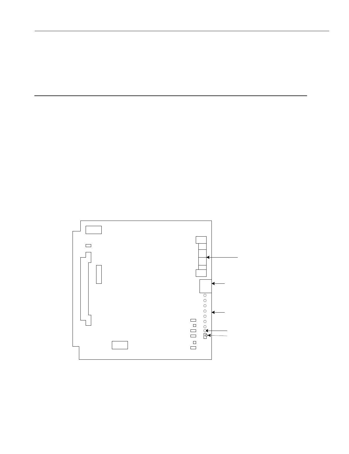
Figure 5. IX-4CSUB-3 Card
Quick Connector for Base
Stations
IAI Service Port
Operation Indicator LEDs
Make Busy Switch
Make Busy LED
CSSP
CSMP
B1
DSW1
SW1
BCONN
CCONN
IX-4CSUB-3
FMW
JP2
JP1
En
g
ineerin
g
Bulletin EBA-2000-28 DRAFT
24 of 105
ADIX Software Version 7.00
Installation Guide and Feature Description
Power Supply Strapping Jack and Jumper Settings
IX4CSUB Switch Settings
IAI Switch Settings
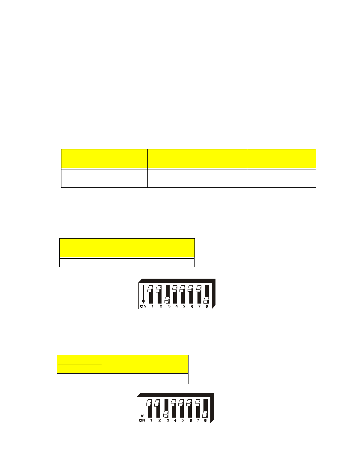
Switches 1-2 on SW1 used exclusively for Iwatsu America’s firmware updates. These
switches must be set to the OFF position.
Figure 6. SW1 Switches 1-2 Settings
Portable Station Setting
Switch 3 on SW1 is used to indicate the type of portable station that the Ome
g
atrek sys-
tem is usin
g
. At this time, Switch 3 is only functional in the ON position.
Figure 7. SW1 Switch 3 Setting
Model: IX-4CSUB-3 Additional Power Requirements:
Part No.: 109412 None
Location: Any universal card slot On-Board Functions: MBSW - Make Busy
Indicators: Make Busy LED, Operation Indicator Indicators: MBLED = Make Busy
LEDs Size: 9.7"H x 9.5"W x.75”D
Connectors: ACONN - Motherboard, Quick Weight: 0.75 lbs.
Connector, Connector for personal
computer
ADIX APS Power Supply
(Factory Setting) External Power Supply
Strappin
g
Jacks J1and J2 No Strap Strap Attached
Jumpers J401 and J402 Intact Cut
Switch Settings Function
1 2
OFF OFF DO NOT SET
Switch Setting Function
3
ON IX-PS6 Settin
g
En
g
ineerin
g
Bulletin EBA-2000-28 DRAFT
25 of 105
ADIX Software Version 7.00
Installation Guide and Feature Description
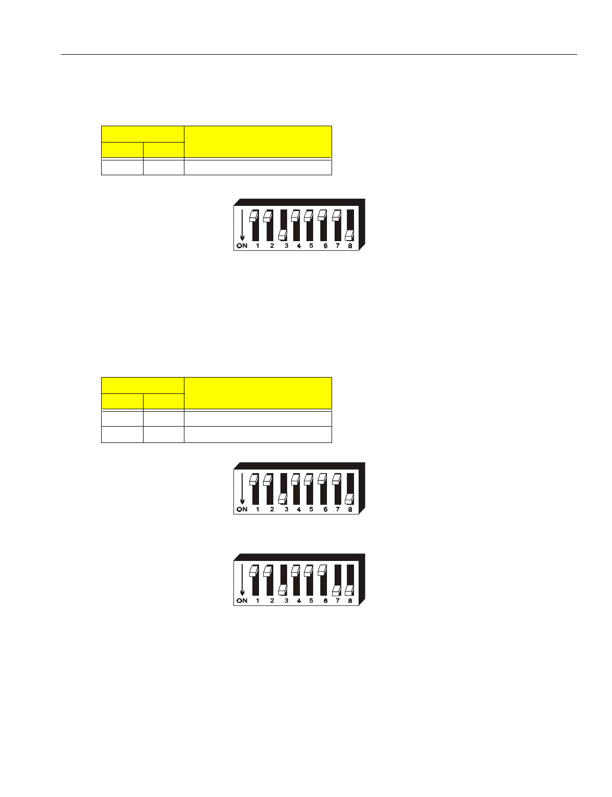
Testing Settings
Switches 3-4 are used for IAI’s testin
g
purposes only. These switches should be set to
OFF.
Figure 8. SW1 Switches 4-5 Switch Settings
Single or Double Highway Settings
The IX-4CSUB-3 card can be placed in either a sin
g
le or dual hi
g
hway slot in the ADIX
APS. In the ADIX 450 (ADIX Classic) and ADIX-M, only sin
g
le slot usa
g
e is available. If
the installation of the IX-4CSUB-3 card is to be in a dual hi
g
hway slot, Switch 6 must be
OFF and Switch 7 must be ON. If the installation of the card is to be in a sin
g
le hi
g
hway
slot, both switches must be OFF.
Figure 9. SWI Switches 6 and 7 Set for Single Highway Usage
Figure 10. SW1 Switches Set for Dual Highway Usage
Switch Settings Function
4 5
OFF OFF DO NOT SET
Switch Settings Function
6 7
OFF OFF Sin
g
le Hi
g
hway Usa
g
e
OFF ON Double Hi
g
hway Usa
g
e
En
g
ineerin
g
Bulletin EBA-2000-28 DRAFT
26 of 105
ADIX Software Version 7.00
Installation Guide and Feature Description
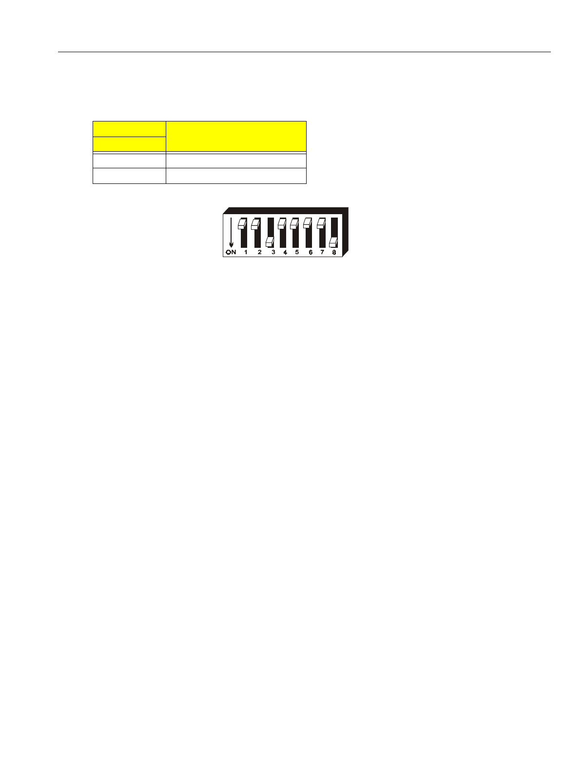
Echo Canceller Setting
SW1 Switch 8 controls the echo cancellin
g
function of the IX-4CSUB-3 card. This switch
should always be set to ON.
Figure 11. SWI Switch 8 Setting
Switch Setting Function
3
ON Echo Cancellin
g
On
OFF Echo Cancellin
g
Off

En
g
ineerin
g
Bulletin EBA-2000-28 DRAFT
27 of 105
ADIX Software Version 7.00
Installation Guide and Feature Description
IX-BS5 Base Station
IX-BS5 base stations can be confi
g
ured as either primary base stations or secondary
base stations. A primary base station transmits and receives a control channel that noti-
fies IX-PS6 portable stations of incomin
g
calls in addition to its three voice channels.
Each cell contains one control channel, so each cell must have a primary base station.
Secondary base stations do not use control channels; they are
g
enerally used to add to
the number of voice channels that a primary base station can handle. Each secondary
base station can transmit four voice channels.
The IX-BS5 should be connected to the ADIX APS with 2-wire star wirin
g
. An IX-BS5
base station is equipped with two antennae. The antenna with hi
g
her sensitivity is auto-
matically selected in order to reduce the effect of phasin
g
.
Note:
This equipment has been tested and found to comply with the limits for a Class B
digital device pursuant to part 15 of the FCC Rules. These limits are designed to
provide reasonable protection against harmful interference in a residential instal-
lation. This equipment generates, uses, and can radiate radio frequency energy
and, if not installed and used in accordance with instructions, may cause harmful
interference to radio communications. However, there is no guarantee that inter-
ference will not occur in a particular installation. If this equipment does cause
harmful interference to radio or television reception, which can be determined by
turning the equipment on and off, the user is encouraged to try to correct the inter-
ference using the following methods:
•Reorient or relocate the receivin
g
antenna.
•Increase the separation between the equipment and receiver.
•Connect the equipment into an outlet on a circuit different from that to which the receiver is
connected.
•Consult the dealer or an experienced radio/TV technician for help.
Chan
g
es or modifications to the IX-BS5 not expressly approved by Manufacturer could
void the user’s authority to operate the product.
Figure 12. IX-BS5 Base Station
En
g
ineerin
g
Bulletin EBA-2000-28 DRAFT
28 of 105
ADIX Software Version 7.00
Installation Guide and Feature Description
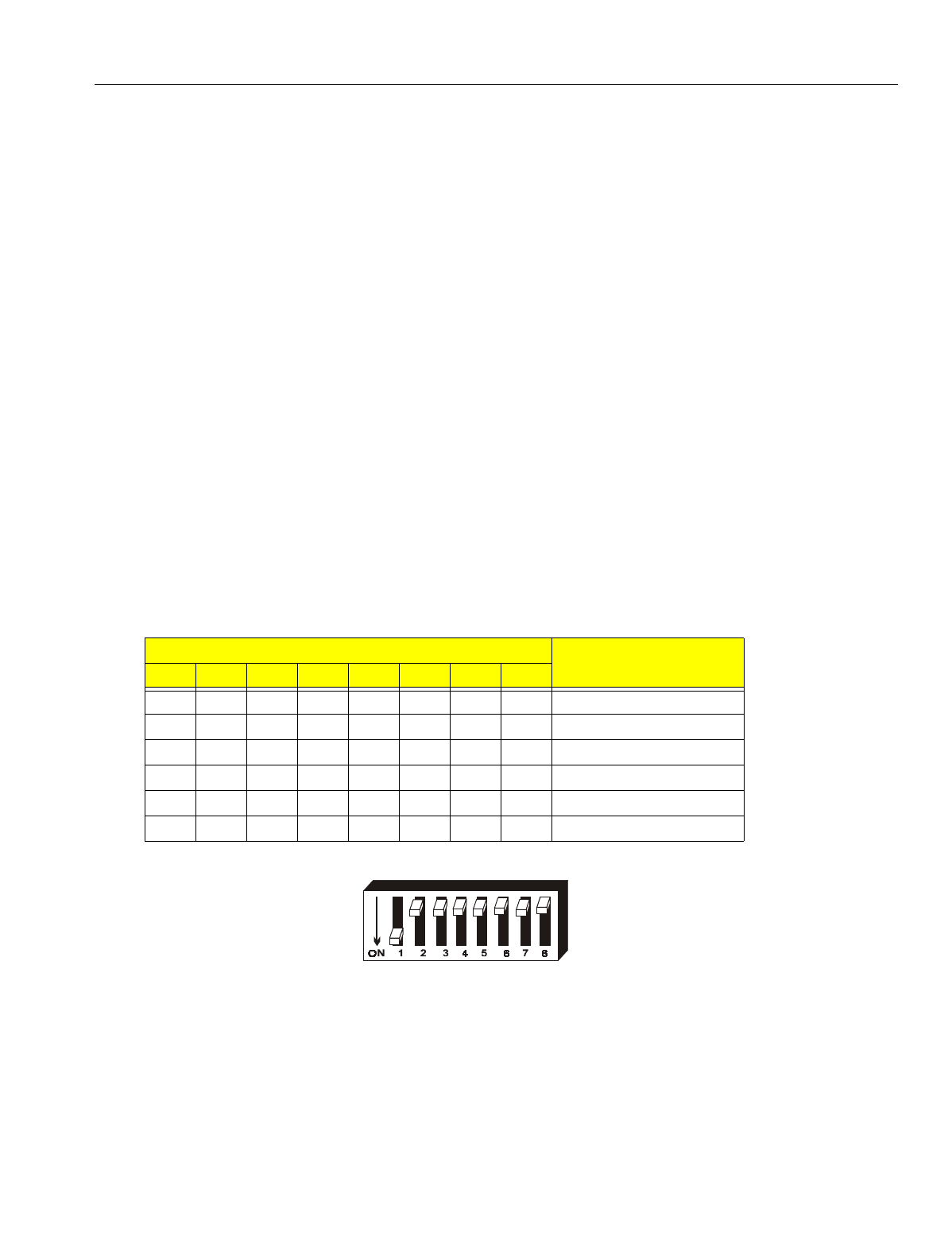
IX-BS5 Switch Positions
Omegatrek ID Programming
SW1 (the lon
g
er switch) on the IX-BS5 is used to set the Ome
g
atrek ID. This lo
g
ical
number is pro
g
rammed in binary usin
g
these switches. See below for an example of
binary settin
g
s for Ome
g
atrek IDs.
Figure 13. IX-BS5 Omegatrek ID Switch Settings
Model: IX-BS5 Operating Temperature:
Item Number 109410 14°F to 122°F
Communication Channels: Frequency Deviation:
3 Voice Channels, ±3 ppm
1 Control Channel Relative Humidity: 10% to 90% (non-condensin
g
)
Wired Transmission System: Channel Spacing: 300 kHz
Pin
g
Pon
g
(1.544 MHz) Size:
Wiring: 2-Wire Star Wirin
g
Weight: 10.5 oz.
Power: Supplied by KSU Communication Mode:
Operation Voltage: 4-Channel Multi-Carriers
21.6-26.4 V DC TDMA-TDD (Time Division
Multiple Access-Time Division
Duplex)
Switch Setting Examples Omegatrek ID Examples
1 2 3 4 5 6 7 8
ON OFF OFF OFF OFF OFF OFF OFF 1
OFF ON OFF OFF OFF OFF OFF OFF 2
OFF OFF ON OFF OFF OFF OFF OFF 3
OFF OFF OFF ON OFF OFF OFF OFF 4
OFF OFF OFF OFF ON OFF OFF OFF 5
OFF OFF OFF OFF OFF ON OFF OFF 6
En
g
ineerin
g
Bulletin EBA-2000-28 DRAFT
29 of 105
ADIX Software Version 7.00
Installation Guide and Feature Description
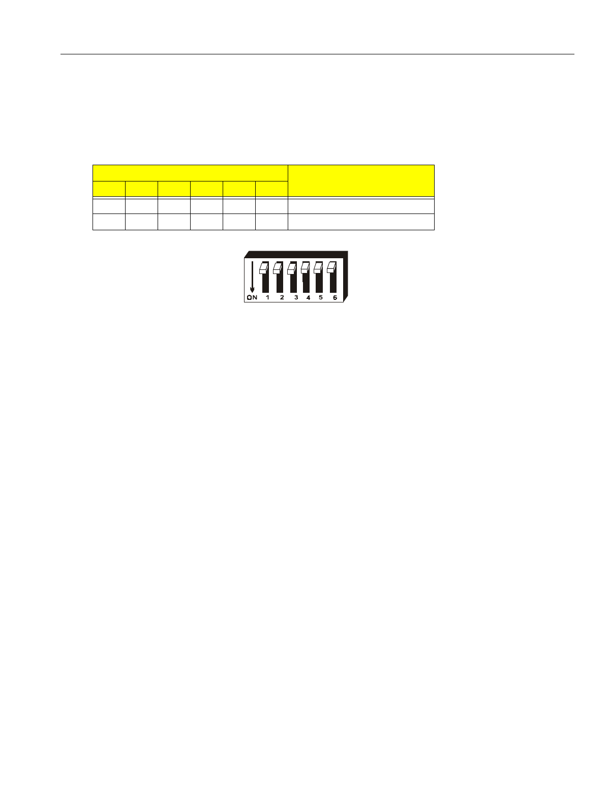
Primary and Secondary Base Station Settings
SW2 (the shorter switch) on the IX-BS5 is used to determine whether the base station is
primary or secondary base station. If the selected base station is to be a primary base
station, switches 1-5 should be set to OFF, and switch 6 should be set to OFF. If the
selected base station is to be a secondary base station, switches 1-5 should be set to
OFF, and switch 6 should be set to ON.
Figure 14. SW2 Primary Base Station Setting
Switch Settings Function
1 2 3 4 5 6
OFF OFF OFF OFF OFF OFF Primary Base Station
OFF OFF OFF OFF OFF ON Secondary Base Station

En
g
ineerin
g
Bulletin EBA-2000-28 DRAFT
30 of 105
ADIX Software Version 7.00
Installation Guide and Feature Description
IX-PS6 Portable Station
The Ome
g
atrek IX-PS6 portable station is a small lithium battery-operated portable tele-
phone that allows users to make and receive calls in a service area. The portable station
has a three-line twelve character LCD display and twenty-nine keys, and
g
ives users
access to a wide ran
g
e of features available with ADIX key telephones. These features
include Hold, Call Transfer, Personal Speed Dial, Placin
g
and Receivin
g
Intercom Calls,
Hands-free Answer Back on Intercom, Least Cost Routin
g
, Conference Call, and Pa
g
in
g
.
The IX-PS6 also includes six multipurpose keys that can be pro
g
rammed usin
g
database
pro
g
rammin
g
.
The user may pro
g
ram the IX-PS6 portable station to rin
g
, vibrate, or to both rin
g
and
vibrate when a call is received. He or she may also select a rin
g
tone for the station and
raise or lower the volume of the handset.
The IX-PS6 portable station includes a jack for an earphone and a port for pro
g
rammin
g
usin
g
the Ome
g
atrek wireless pro
g
rammer.
Figure 15. IX-PS6 portable station
Model: IX-PS6 LCD Display: 3 lines, 12 character Dot Matrix
Part Number: 109400 Key Pad: 29 Keys
Battery: 3.6 V Lithium Ion Memory: 500 Name/Number Entries
Charge Time: 6 hours Size 5.5" (H) x 1.7" (W) x 0.9" (D)
Talk Time: 4.5 hours Weight: 3.7 oz.
Standby Time: 320 hours Operational Features:
Typical Operating Range from IX-BS5: Auto Answer, Speed Dial, Call Transfer, Call
150 feet typical indoor Hold, Dial by Name, Conferencin
g
, Redial,
Any Key Answer, Key Lock, Dial Lock, Call
Lo
g
, Telephone Directory, Call Forwardin
g
En
g
ineerin
g
Bulletin EBA-2000-28 DRAFT
31 of 105
ADIX Software Version 7.00
Installation Guide and Feature Description
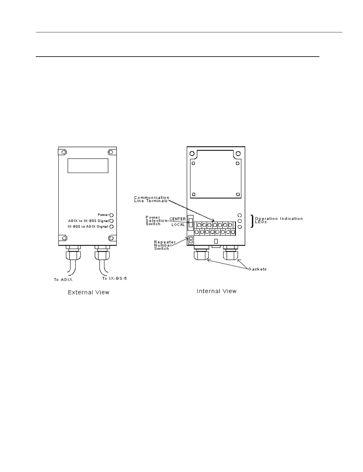
IX-BSREP Repeaters
Repeaters are used to extend the distance that a radio si
g
nal can travel between the
ADIX APS and an IX-BS5 base station and are used when the wirin
g
distance for an IX-
BS5 base station exceeds 3,280 feet. One repeater adds 6,562 feet to the distance cov-
ered; two repeaters add 13,123 feet.
Each repeater includes LEDs indicatin
g
power, reverse transmission, and forward trans-
mission. Connectors for the ADIX, the motherboard, and an outside power source are
also included.
Figure 16.IX-BSREP repeater
Model: IX-BSREP Operating Voltage: +21.6 V to +26.4 V DC
Part No.: 109411 Operating Temperature:
Power: Supplied by ADIX APS 14o F -122o F
Additional Power Requirements: Relative Humidity: 10% to 90% (non-condensin
g
)
None Indicators: Power Indicator Lamp
Weight: .75 lbs. Operation Indicator Lamps
Indicators: Power LED, Trunk Data LED, Connectors: ACONN - Motherboard
Rev Data LED CCONN - Station Terminals

En
g
ineerin
g
Bulletin EBA-2000-28 DRAFT
32 of 105
ADIX Software Version 7.00
Installation Guide and Feature Description
IX-PSBP Lithium Ion Battery
The lithium ion battery included with the IX-PS6 portable station provides four and a half
hours of talk time and up to three hundred twenty hours of standby time when fully
char
g
ed. It fits snu
g
ly into the battery compartment of the IX-PS6 portable station and is
attached by placin
g
the IX-PSBP battery’s connector into the battery connector in the IX-
PS6 portable station’s battery compartment.
The IX-PSBP battery is fully rechar
g
able. Use the IX-PSCG battery char
g
er to rechar
g
e
the battery while the battery is inside the IX-PS6 portable station.
CAUTION
Replace batter
y
with Iwatsu P/N IX-PSBP onl
y
. Use of another batter
y
ma
y
present a risk of
fire or explosion. See the Ome
g
atrek Owners’ Manual for safet
y
instructions.
There is a dan
g
er of explosion if the batter
y
is incorrectl
y
replaced.
Replace this batter
y
onl
y
with the same or equivalent t
y
pe recommended b
y
the manufac-
turer. Dispose of used batteries accordin
g
to the manufacturer’s instructions.
Figure 17. IX-PSBP lithium ion battery
Model: IX-PSBP Charge Time: Approximately 7 Hours for fully
Part Number 109415 dischar
g
ed battery
Battery Type: Lithium Ion Rechar
g
eable Battery Talk Time: Over 4.5 Hours (fully char
g
ed)
Power 3.6 V, 600 mAH Standby Time: Over 320 Hours (fully char
g
ed)
Charge: Non-contact Char
g
in
g
with
IX-PSCG Char
g
er
IX-PSBP
En
g
ineerin
g
Bulletin EBA-2000-28 DRAFT
33 of 105
ADIX Software Version 7.00
Installation Guide and Feature Description
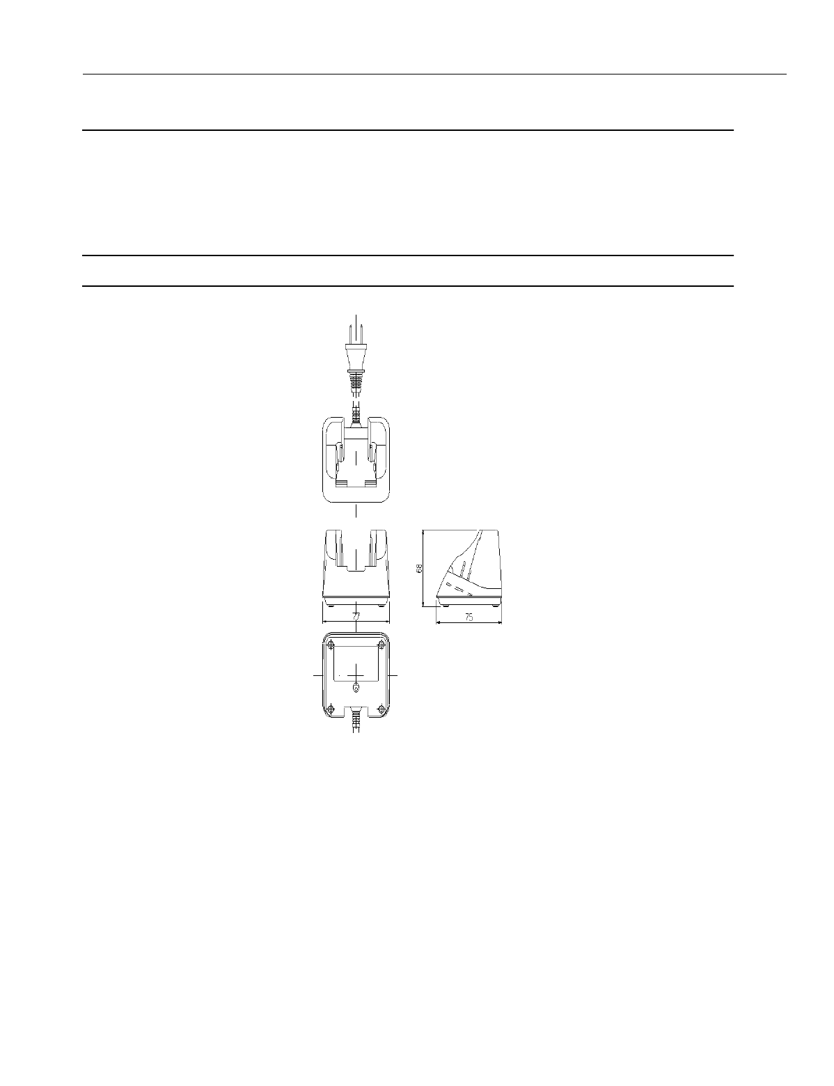
IX-PSCG Battery Charger
The IX-PSCG battery char
g
er is a non-contact battery char
g
er specifically desi
g
ned for
IX-PS6. Its features include a Char
g
e Lamp Indicator, which displays a steady
g
reen li
g
ht
when the char
g
e is complete, a steady red li
g
ht to indicate that the IX-PS6 portable sta-
tion is char
g
in
g
, and a flashin
g
red li
g
ht to indicate abnormal battery char
g
in
g
Note:
The IX-PSCG should be installed near an easitly accessible power outlet.
.
Figure 18. IX-PSCG Battery Charger
Model: IX-PSG Relative Humidity: 90% or less (non-condensin
g
)
Part Number: 109416 95% or Less (non-condensin
g
) for Stora
g
e
Operating Temperature: Input Voltage: 120 V ±12 V AC 57 to 63 Hz
0° to 40°C (32° to 104°F) Power Consumption: Max. 4 VA
Charge Temperature: Output Current: 10 mA
5° to 35°C (41° to 95°F) Weight: About 5.6 oz
Storage Temperature:
20° to 60°C (-4° to 140°F)
Size: 2.9” x 2.2” x 2.9”
En
g
ineerin
g
Bulletin EBA-2000-28 DRAFT
34 of 105
ADIX Software Version 7.00
Installation Guide and Feature Description
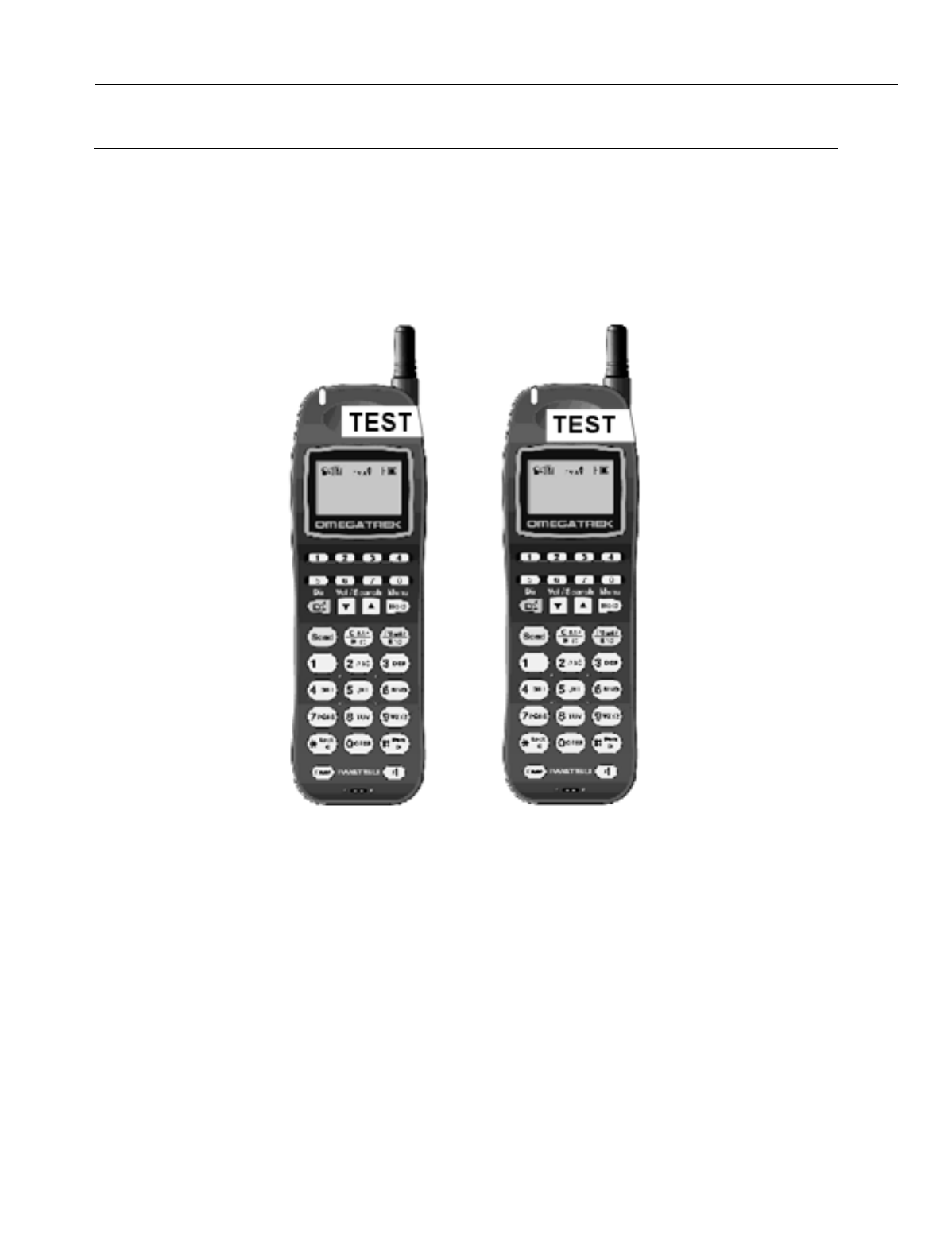
IX-PSMK Omegatrek Site Measurement Kit
The Ome
g
atrek Site Measurement Kit is used to measure the EMF si
g
nals from the
mapped position of a base station to anticipated positions of portable stations. It consists
of two portable stations without audio, with two portable station batteries and portable sta-
tion char
g
ers.
This tool is useful when plannin
g
installation of the Ome
g
atrek system.
Figure 19. IX-PSMK Omegatrek Site Measurement Kit
Model: IX-PSMK Standby Time: 320 hours
Part Number: 109425 LCD Display: 3 lines, 12 character Dot Matrix
Batteries (2): 3.6 V Lithium Ion Key Pad: 29 Keys
Charge Time: 6 hours Size 5.5" (H) x 1.7" (W) x 0.9" (D)
Test Time: 4.5 hours Weight: 3.7 oz.

En
g
ineerin
g
Bulletin EBA-2000-28 DRAFT
35 of 105
ADIX Software Version 7.00
Installation Guide and Feature Description
S
y
stem Plannin
g
and Installation
Cell Planning
To provide a service area that meets the customer needs, the base stations must be posi-
tioned in such a way that there are as few dead cells (where radio si
g
nals do not reach)
as possible. First, decide the positions of base stations on paper. To do so, obtain the fol-
lowin
g
information from the customer.
•A floor plan
•A map of the desired service area
On the floor plan, draw circles, usin
g
a compass, with the positions of base stations as
centers. In a normal office environment, the radius is about 165 feet.
Note:
The radio si
g
nals from a base station reach as far as 330 feet in an open area. However,
the distance may be shortened due to the buildin
g
structure and installation environments.
The followin
g
structures obstruct si
g
nal travel:
•Metallic Structures (Elevators, Fire Doors,
Shutters, Lockers, Etc.)
•Columns, Walls, Floors, and Ceilin
g
s
The followin
g
structures obstruct si
g
nal travel minimally:
•Window Panes (excludin
g
infrared reflect-
in
g
g
lasses)
•Stairwells and Stairs
Consider the above objects when plannin
g
the positions of base stations on paper. Radio
si
g
nals travel in different ways in similar-lookin
g
offices. There is no standardized method
of plannin
g
cells.
Followin
g
are recommended places to install base stations:
•Open spaces
•Elevated places above obstacles
•Wall surfaces (The back of ceilin
g
s
g
reatly reduces radio si
g
nals, compared to wall surfaces.)
•Places free of metallic objects, ducts, etc.

En
g
ineerin
g
Bulletin EBA-2000-28 DRAFT
36 of 105
ADIX Software Version 7.00
Installation Guide and Feature Description
Using the Omegatrek Site Measurement Kit for Signal Checking
Before conductin
g
a si
g
nal check, prepare the followin
g
for the service area in which the
Ome
g
atrek system is to be installed:
•A floor plan
•A survey of buildin
g
conditions
•A map of the desired service area
As is often the case, cell plannin
g
on paper may not work well in an actual system instal-
lation. For this reason, you should check si
g
nal conditions at the installation site before-
hand.
The Ome
g
atrek Site Measurement Kit measures EMF stren
g
th from the position at which
you will place the base station to various positions where you anticipate portable station
positionin
g
. This feature is very helpful durin
g
the installation process to determine loca-
tions of the base stations.
To use the Ome
g
atrek Site Measurement Kit to determine the positions of base stations:
1. Remove the test portable stations from the boxes, insert the batteries, and fully char
g
e the
units.
2. Determine the desired locations of all base stations and probable movement areas for all
associated portable stations.
3. On one of the test portable stations, press [POWER] [#] [4] simultaneously. The password
screen displays.
4. Press [5] + [1] + [6] + [2]. The Class 1 screen displays.
5. Press [2] + [HOLD] to enter Class 02. The Item screen displays.
6. Press [2] + [HOLD] to enter Item 02. The Element screen displays.
7. Press [1] + [HOLD]. The Ome
g
atrek ID screen displays.
8. Enter any number to serve as the Ome
g
atrek ID. Record or remember the number that you
enter at this screen.
9. Press [HOLD] after you have entered and properly recorded the Ome
g
atrek ID. The Element
4 screen displays.
10. Press [HOLD]. The Class 2, Item 2, Element 4 screen displays.
11. Enter an ID number, record or remember the number, then press [HOLD]. The Write Com-
pleted screen displays briefly.
12. Turn the test portable station OFF.
13. Follow steps 3-10 for the second portable station usin
g
a different Ome
g
atrek ID.
14. Turn both test portable stations ON.
15. Use the first test portable station to call the second portable station.
16. Answer the second portable station.
17. Press [FEAT] + [1] on both test portable stations. The EMF stren
g
th displays.
18. Place one test portable station at the location where you wish to install a base station.
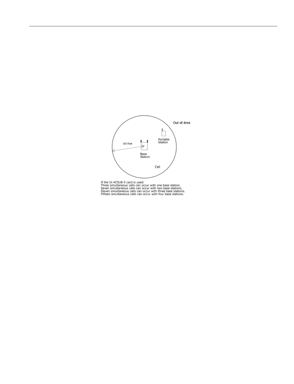
En
g
ineerin
g
Bulletin EBA-2000-28 DRAFT
37 of 105
ADIX Software Version 7.00
Installation Guide and Feature Description
19. Takin
g
the other test portable station with you,
g
o to the sites where you anticipate there will
be portable station traffic. Check the EMF stren
g
th in all of these areas. An EMF stren
g
th of
40 is sufficient to support most portable station communications.
20. If there is a problem with the si
g
nal stren
g
ths or the error rates, chan
g
e the position of the
base station (represented by a portable station) or review the cell plannin
g
on paper; then
repeat a si
g
nal check.
Cell Traffic Assessment
Based on the customer's traffic assessment (the number of portable stations per cell),
determine the number of base stations per cell. The maximum number of base stations
and the maximum number of simultaneous calls in a cell are shown in Fi
g
ure 19.
Figure 20. Maximum Number of Base Stations and Simultaneous Calls in a Cell
Sub-Cell Group Registration
Portable stations in the same sub-cell
g
roup have the same key lamp indications and the
same key pattern assi
g
nment of the cell
g
roup keys. Use the database pro
g
rammin
g
to
assi
g
n each station to a sub-cell
g
roup.

En
g
ineerin
g
Bulletin EBA-2000-28 DRAFT
38 of 105
ADIX Software Version 7.00
Installation Guide and Feature Description
System Capacity
System Item Slot Port Remarks
Total Number of Ports 448
Number of Free Slots 56 Excludin
g
slots used for IX-CPUP/
HW
Number of Reserved Slots 7
Total Number of Trunks 200
Di
g
ital Trunks IX-2ICOTB 33 132
IX-ICOTP 8 184
Total Number Of Stations 400
Number of Actual Station Ports 400
Key Telephone IX-12KTx 392 Can be reduced by usin
g
IX-CSUB
Busy Bypass IX-BPAD 196
SATT IX-12KTD 8 At least one is required
DSS Console IX-DSSB 8
Attendant Console IX-ATT 8
BLF IX-BLF 8
Di
g
ital Doorphone IX-DDPH 391
Messa
g
e Card IX-MSGU 8 32
Sin
g
le-Line Telephone IX-8SUBS-2 384
Off-premises Station IX-4SUBL 212
Di
g
ital Cordless Station IX-PS 392 # of units that can be accommodated
Number of Simultaneous Calls 378
Base Station IX-BS5 108 Up to 100 cells
IX-4CSUB-3 27
Remote Maintenance Card IX-RMPU 1 8 Built-in DTMF Receiver
Serial Communications Card IX-SCIF 1 0
MISC + SCIF Card IX-EDVIF 1 8
MISC Card IX-MISC 7 56
IX-RCVPM 2
DTMF Receiver IX-4RCVC 16
Additional Units Item Quantity
Rin
g
Generator IX-RNGUM 0
IX-RNGU 4
PC Pro
g
rammer 1

En
g
ineerin
g
Bulletin EBA-2000-28 DRAFT
39 of 105
ADIX Software Version 7.00
Installation Guide and Feature Description
Restrictions
•The system needs at least one attendant station, at least one di
g
ital station card, and at least
one trunk card.
•The system accommodates up to twenty-seven IX-4CSUB-3 cards, up to one hundred and
ei
g
ht base stations, and up to 392 portable stations.
•If another card is installed next to an IX-4CSUB-3 card, the maximum number of simultaneous
calls usin
g
the IX-4CSUB-3 card decreases from fifteen to ei
g
ht. If another card must be
installed next to an IX-4CSUB-3 card, limit the number of base stations connected to the IX-
4CSUB-3 card to two.
•Any combination of these cards is allowed as lon
g
as the total number of trunks, extensions,
and miscellaneous ports does not exceed the total number of ports.
•Any combination of the above stations is allowed as lon
g
as the number of stations does not
exceed the total number of actual station ports.
•Any combination of trunk cards is allowed as lon
g
as total number of cards does not exceed
the total number of trunks.
•At least one KT (IX-12KTD) should be set up as an attendant station for system pro
g
rammin
g
,
so at least one di
g
ital station card (IX-8PSUB-1, etc.) should be installed.
•At least one trunk card must be installed in the system or the system will not be operational.
•The wirin
g
distance between the ADIX and the base station should be 820 feet or fewer usin
g
1 pair AWG22. This distance varies accordin
g
to wirin
g
type and pair number. For a lon
g
er
distance, a repeater could be required. See the
Wirin
g
Distance
section of this document for
more information.

En
g
ineerin
g
Bulletin EBA-2000-28 DRAFT
40 of 105
ADIX Software Version 7.00
Installation Guide and Feature Description
Determining IX-4CSUB-3 Position in the ADIX
The IX-4CSUB-3 card is a 16 port card that can be placed on either a sin
g
le or dual hi
g
h-
way. In determinin
g
the placement of the IX-4CSUB-3 card and the DSW1 settin
g
s of
that card, it is necessary to understand the system hi
g
hway structure, as well as the func-
tional relationships between slot numbers, port numbers, and physical card numbers.
A dual hi
g
hway shelf contains three (3) 32-channel hi
g
hways. There are two (2) different
types of cabinets that contain dual hi
g
hway shelves.
The ADIX-APS IX-CML and ADIX-S/M IX-CMM cabinets provide the first type of dual
hi
g
hway shelf. This type shelf provides a T-1 type slot (3-card slot) at the far left of the
shelf that supports 24 ports and 8 additional ports. There is no physical card slot associ-
ated with these 8 ports. The next 4 slots are all 16-port card slots (2-card slots) sup-
ported by two 32-channel hi
g
hways. One 32-channel hi
g
hway (Primary Hi
g
hway)
supports the first 8 ports on each of the 4 slots. The other 32-channel hi
g
hway (Second-
ary Hi
g
hway) supports the second 8 ports on each of the 4 slots.
The ADIX-APS IX-EXPML cabinet provides the second type of dual hi
g
hway shelf. This
type shelf provides a T-1 slot (3-card slot) at the far left of the shelf that supports 24 ports
and a sin
g
le card type slot (1-card slot) that supports 8 ports all within the first 32-channel
hi
g
hway. The next 4 slots are all 16-port card slots (2-card slots) supported by two 32-
channel hi
g
hways. One 32-channel hi
g
hway (Primary Hi
g
hway) supports the first 8 ports
on each of the 4 slots. The other 32-channel hi
g
hway (Secondary Hi
g
hway) supports the
second 8 ports on each of the 4 slots.
A sin
g
le hi
g
hway shelf contains one 32-channel hi
g
hway for every 4 sin
g
le card slots sup-
portin
g
a maximum of 64 ports.
In an ADIX-M system, there is a T-1 slot (3-card slot) at the far left of the shelf that sup-
ports 24 ports and a sin
g
le card type slot (1-card slot) that supports 8 ports all within the
first 32-channel hi
g
hway. The next 4 slots in the shelf are all sin
g
le card type slots (1-card
slots), supportin
g
8 ports each all within the second 32-channel hi
g
hway of the shelf.
In an ADIX IX-CM (Classic or Full Size 450) system, the first 4 sin
g
le card type slots (1
card slots), supportin
g
8 ports each are all within the first 32-channel hi
g
hway. The sec-
ond 4 sin
g
le card type slots (1-card slots), supportin
g
8 ports each are all within the sec-
ond 32-channel hi
g
hway.
The slot number is an actual universal card slot location in the ADIX cabinet where any
station, trunk or miscellaneous card can be placed. The slots are numbered from left to
ri
g
ht. Each ADIX cabinet type has a different number of slots. See Fi
g
ures 20, 21 and 22
in this section for the slot numbers in each ADIX cabinet.
The physical card number is the unique number assi
g
ned to a specific card slot in a
system. This number identifies the actual physical location (specific hi
g
hway slot and
shelf) where a card resides in the system.
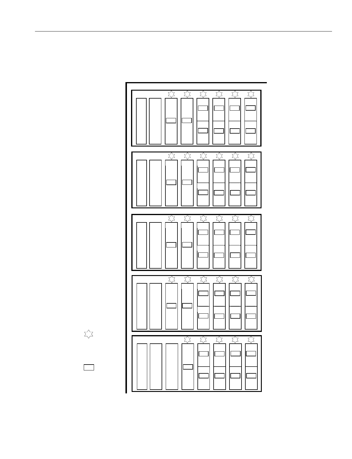
En
g
ineerin
g
Bulletin EBA-2000-28 DRAFT
41 of 105
ADIX Software Version 7.00
Installation Guide and Feature Description
ADIX APS Card Numbers
Fi
g
ure 20 lists the physical card numbers of each shelf in an ADIX-APS.
Figure 21. ADIX APS Slot Numbers, Port Numbers, and Card Numbers
6
5
4
3
2
1
5
4
3
2
1
Slot
Number
Port
Number
Bold
Text
Physical
Card
Number
CPU
Card
Slot
097-128
17-20
001-008 009-016 017-024 025-032
5 6 7 8
21 22 23 24
129-136 137-144 145-152 153-160
225-248 249-256 033-040 041-048 049-056 057-064
161-168 169-176 177-184 185-192
33-35 36
9 10 11 12
25 26 27 28
6
5
4
3
2
1
257-280 281-288 065-072 073-080 081-088 089-096
193-200 201-208 209-216 217-224
37-39 40
13 14 15 16
29 30 31 32
6
5
4
3
2
1
353-376 377-384 289-296 297-304 305-312 313-320
417-424 425-432 433-440 441-448
49-51 52
41 42 43 44
57 58 59 60
6
5
4
3
2
1
385-408 409-416 321-326 327-336 337-344 345-352
449-456 457-464 465-472 473-480
53-55 56
45 46 47 48
61 62 63 64
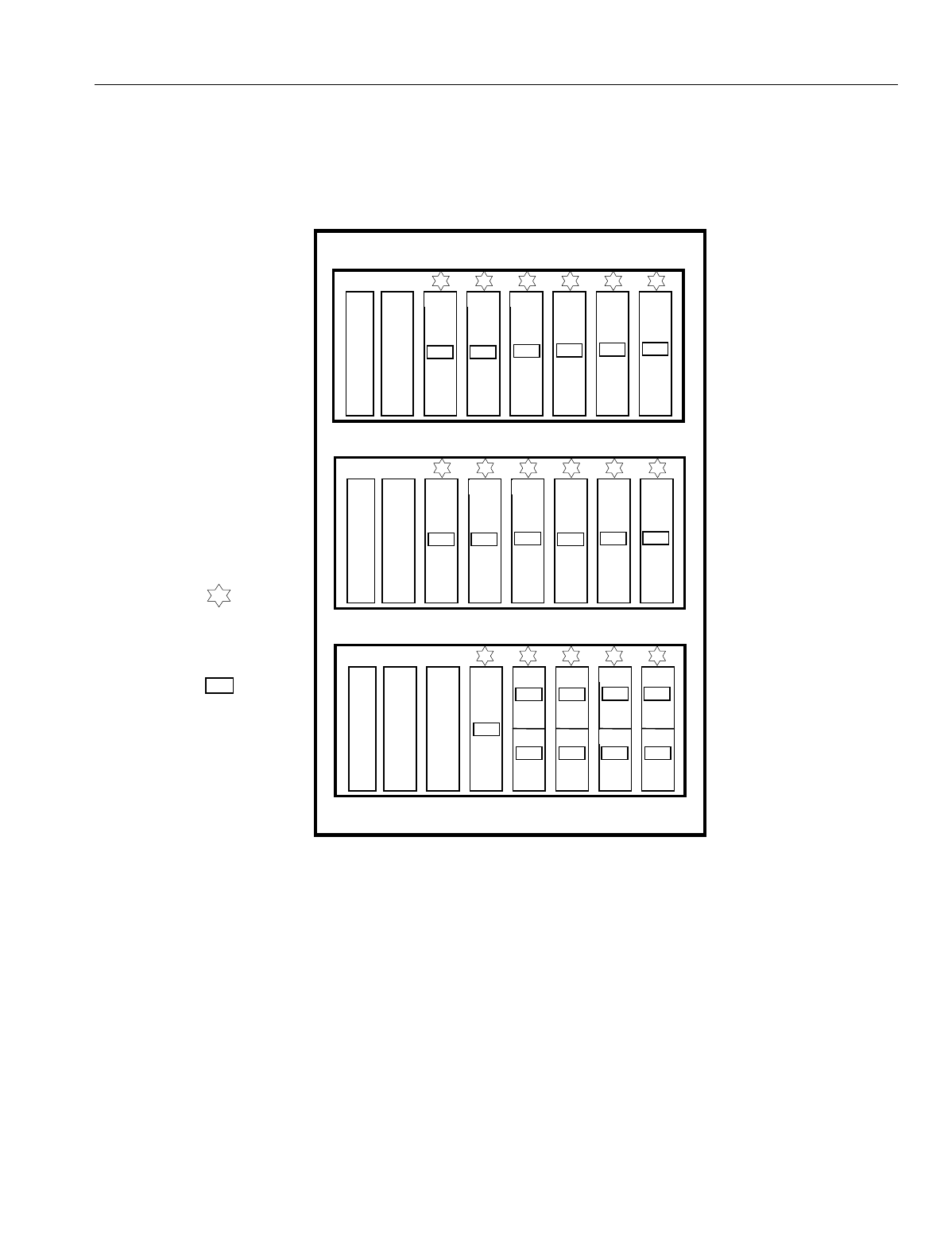
En
g
ineerin
g
Bulletin EBA-2000-28 DRAFT
42 of 105
ADIX Software Version 7.00
Installation Guide and Feature Description
ADIX-M Card Numbers
Fi
g
ure 21 lists the physical card numbers of each shelf in an ADIX-M.
Figure 22. ADIX-M Slot Numbers, Port Numbers, and Card Numbers
5
4
3
2
1
CPU
Card
Slot
097-128
17-20
001-008 009-016 017-024 025-032
5 6 7 8
21 22 23 24
129-136 137-144 145-152 153-160
Slot
Number
Port
Number
Bold
Text
Physical
Card
Number
6
5
4
3
2
1
161-184 185-192 033-040 041-048 049-056 057-064
9 10 11 12
6
5
4
3
2
1
193-216 217-224 065-072 073-080 081-088 089-096
13 14 15 16
29-31 32
25-27 28
En
g
ineerin
g
Bulletin EBA-2000-28 DRAFT
43 of 105
ADIX Software Version 7.00
Installation Guide and Feature Description
ADIX 450 Card Numbers
Fi
g
ure 22 lists the physical card numbers of each shelf in an ADIX 450.
Figure 23. ADIX Slot Numbers, Port Numbers, and Card Numbers
6
5
4
3
2
1
273-280 281-288 289-296 297-304 305-312 313-320
39 40 41 42 43 44
Slot
Number
Port
Number
Bold
Text
Physical
Card
Number
7 8
265-272
257-264
38
37
6
5
4
3
2
1
337-344 345-352 353-360 361-368 369-376 377-384
47 48 49 50 51 52
7 8
329-336
321-328
46
45
6
5
4
3
2
1
401-408 409-416 417-424 425-432 433-440 441-448
55 56 57 58 59 60
7 8
393-400
385-392
54
53
6
5
4
3
2
1
465-472 473-480
63 64
7 8
457-464
449-456
62
61
4
3
2
1
001-008 009-016 017-024 025-032
4 5 6 7 8
6
5
4
3
2
1
049-056 057-064 065-072 073-080 081-088 089-096
11 12 13 14 15 16
7 8
041-048 033-040
10
9
6
5
4
3
2
1
113-120 121-128 129-136 137-144 145-152 153-160
19 20 21 22 23 24
7 8
105-112 097-104
18
17
6
5
4
3
2
1
177-184 185-192 193-200 201-208 209-216 217-224
27 28 29 30 31 32
7 8
169-176 161-168
26
25
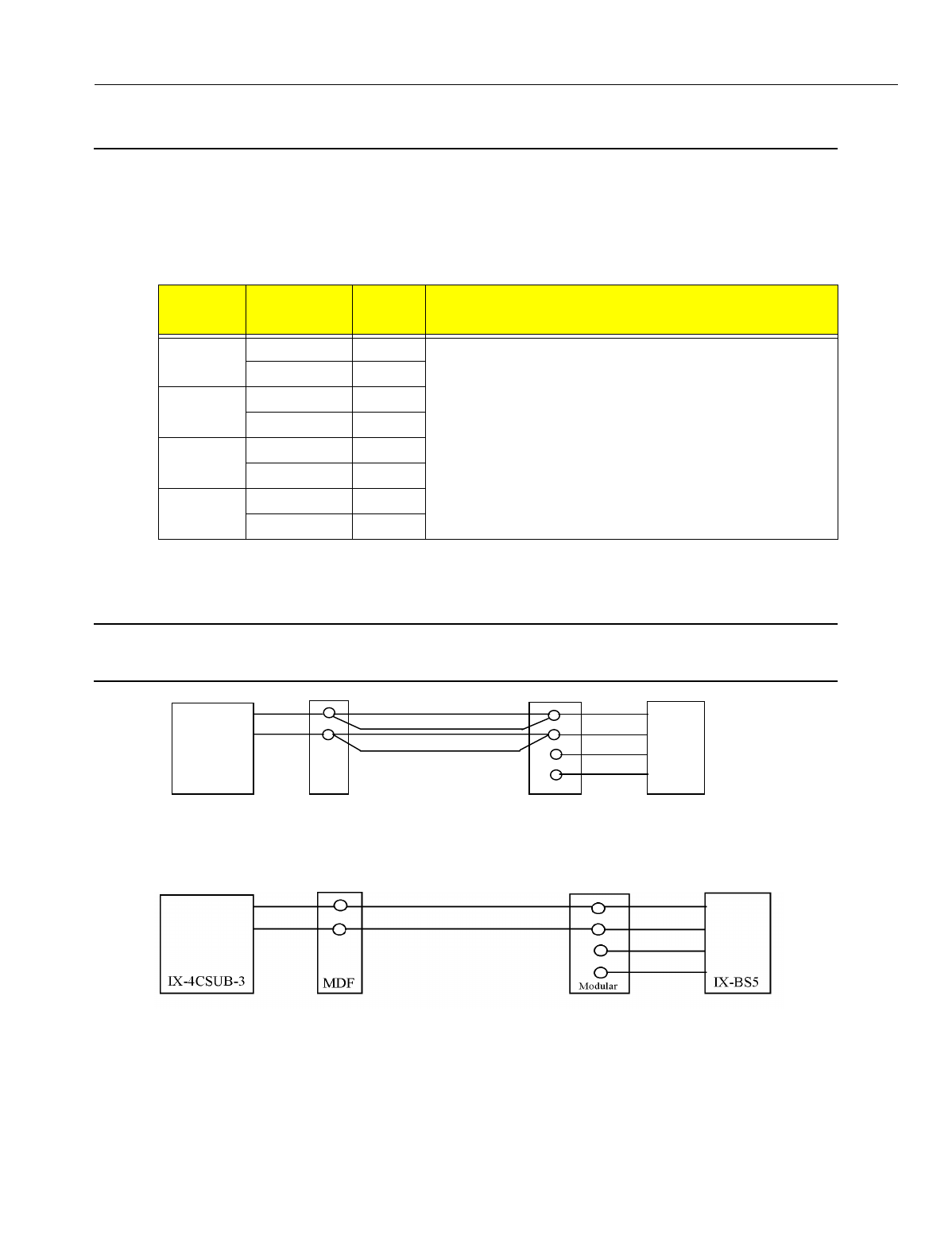
En
g
ineerin
g
Bulletin EBA-2000-28 DRAFT
44 of 105
ADIX Software Version 7.00
Installation Guide and Feature Description
Wiring Planning
Wiring Distance Using No Repeaters
See the table below for cable and distance information about wirin
g
without usin
g
a
repeater.
When usin
g
two pair cablin
g
, you must attach the second pair to the first pair as shown
below.
Note:
Do not use local power if you follow this configuration. Problems may arise from
use of local power, and local power provides no advantage in distance
.
Figure 24. Wiring Setup Using 2 Pair and No Repeaters
Figure 25. Wiring Setup Using 1 Pair and No Repeaters
Cable
Diameter
Number of
Cable Pairs
Wire
Length Remarks
AWG26 1 290 ft.
Varies with the transmission characteristics of the si
g
nal
lines.
2 490 ft.
AWG24 1 460 ft.
2 790 ft.
AWG22 1 820 ft.
2 1340 ft.
AWG18 1 1870 ft.
2 3180 ft.
IX-4CSUB-3 MDF Modular IX-BS5
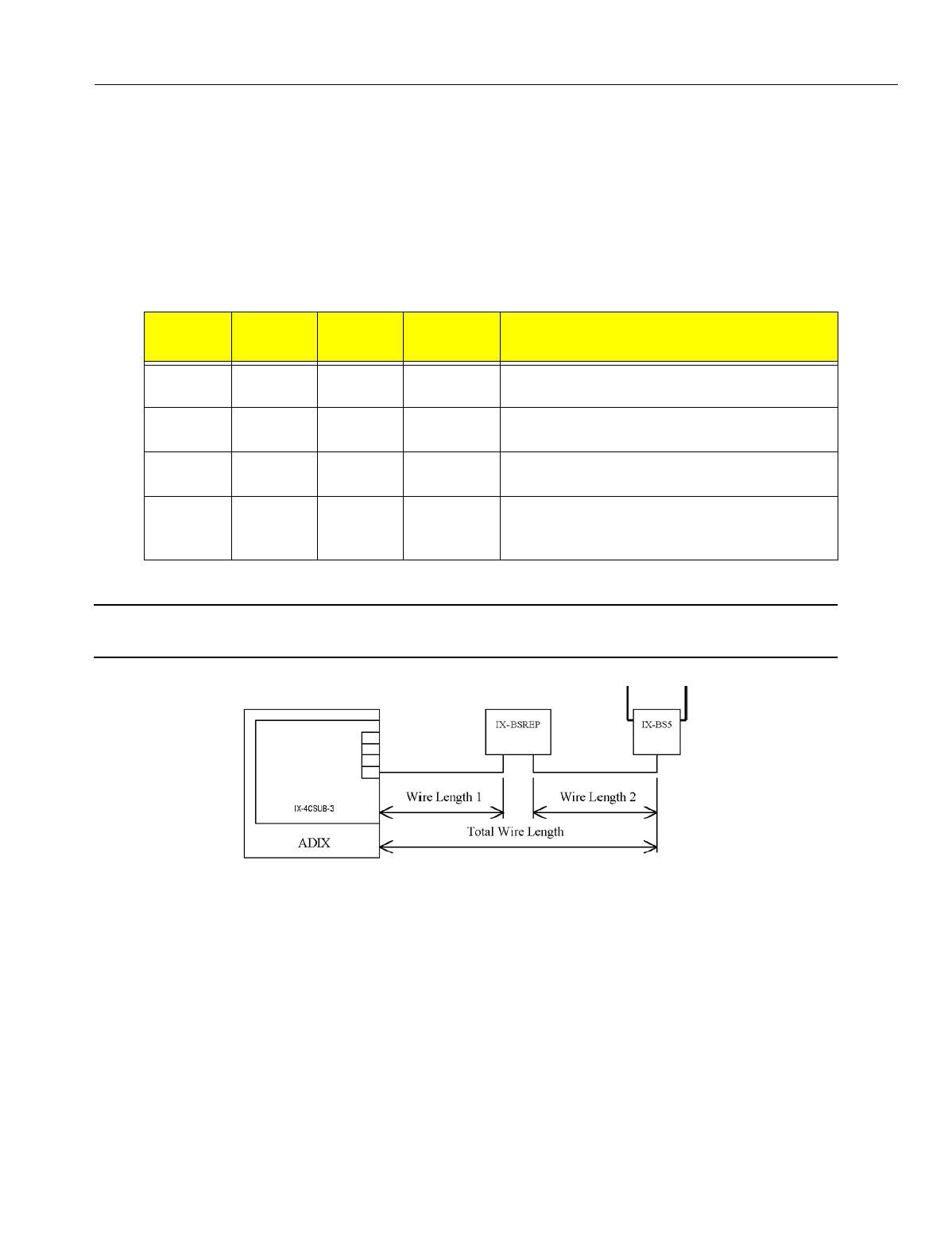
En
g
ineerin
g
Bulletin EBA-2000-28 DRAFT
45 of 105
ADIX Software Version 7.00
Installation Guide and Feature Description
Wiring Distance Using One Repeater
All IX-BSREP units require a local power. Use Valcom VP-624B AC/DC Power supply
(DC +24V, 600mA). Note that all local power units require an UPS unit for uninterrupted
operation.
•To set up the IX-BSREP for use as the only repeater:
1. Set IX-BSREP's SW1 (Power Settin
g
SW) to "Local" side.
2. Set IX-4CSUB-3's JP1&2 (Power Selection) to "Center"..
See the illustration below for a wirin
g
installation dia
g
ram if you plan to use one repeater
CAUTION
Use onl
y
one pair cable.
Figure 26.Wiring Setup with One Repeater
Cable
Diameter
Wire
Length 1
Wire
Length 2
Total Wire
Length Remarks
AWG26 3900 ft. 300 ft. 4200 ft. The total wire len
g
th is the same if no repeater
is used.
AWG24 3900 ft. 550 ft. 4450 ft. The total wire len
g
th is the same if no repeater
is used.
AWG22 3900 ft. 950 ft. 4850 ft. The total wire len
g
th is the if when no repeater
is used.
AWG18 3900 ft. 2200 ft. 6100 ft. Varies with the transmission characteristics of
the si
g
nal lines.The total wire len
g
th is the
same if no repeater is used.
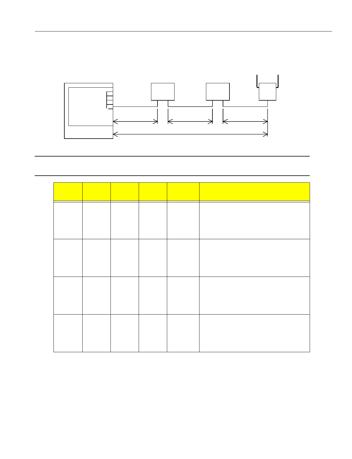
En
g
ineerin
g
Bulletin EBA-2000-28 DRAFT
46 of 105
ADIX Software Version 7.00
Installation Guide and Feature Description
Wiring Distance Using Two Repeaters
See illustration below for a wirin
g
installation dia
g
ram if you plan to use two repeaters.
Figure 27. Wiring Setup with Two Repeaters
CAUTION
Use onl
y
one pair cable.
Cable
Diameter
Wire
Length 1
Wire
Length 2
Wire
Length 3
Total Wire
Length Remarks
AWG26 3200 ft. 3900 ft. 340 ft. 7550 ft. The volta
g
e near the quick connector on
the IX-4CSUB-3 card should be 26 V or
hi
g
her. If the number of cable pairs is one
or two, the total wire len
g
th becomes
shorter than when no repeater is used.
AWG24 3200 ft. 3900 ft. 560 ft. 7770 ft. The volta
g
e near the quick connector on
the IX-4CSUB-3 card should be 26 V or
hi
g
her. If the number of cable pairs is one
or two, the total wire len
g
th becomes
shorter than when no repeater is used.
AWG22 3200 ft. 3900 ft. 950 ft. 8160 ft. The volta
g
e near the quick connector on
the IX-4CSUB-3 card should be 26 V or
hi
g
her. If the number of cable pairs is one
or two, the total wire len
g
th becomes
shorter than when no repeater is used.
AWG18 3200 ft. 3900 ft. 2200 ft. 9400 ft. The volta
g
e near the quick connector on
the IX-4CSUB-3 card should be 26 V or
hi
g
her. If the number of cable pairs is one
or two, the total wire len
g
th becomes
shorter than when no repeater is used.
ADIX
IX-4CSUB-2
IX-BSREP
Wire Length 1 Wire Length 2
Total Wire Length
IX-BSREP IX-BS5
Wire Length 3
IX-4CSUB-3

En
g
ineerin
g
Bulletin EBA-2000-28 DRAFT
47 of 105
ADIX Software Version 7.00
Installation Guide and Feature Description
Environmental and Structural Conditions
The Ome
g
atrek Wireless System should be operated only under the followin
g
environ-
mental and structural conditions:
Operating Temperature: 0 to 40 de
g
rees Centi
g
rade (32 to 104 de
g
rees Fahrenheit)
Storage Temperature: -10 to 50 de
g
rees Centi
g
rade (14 to 122 de
g
rees Fahrenheit)
Relative Humidity (non-condensing): 10 to 90% at 24 de
g
rees Centi
g
rade (75 de
g
rees Fahrenheit)
Static Discharge: 10 KV or less
Electromagnetic Interference: 0.3 V/ft. or less
Ventilation: At least three inches above and to the sides of the
IX-CML/IX-EXPML and power suppl
y
Floor Strength: 200 lbs. per sq. ft.
System Power Supply Input
Voltage (IX-PWSL):
120 VAC +/- 10% 60 Hz

En
g
ineerin
g
Bulletin EBA-2000-28 DRAFT
48 of 105
ADIX Software Version 7.00
Installation Guide and Feature Description
Software Setup
PC Programmer Compatibility Chart -- ADIX
S
y
stem
Software
Version 3.12
3.41
3.41B 3.51A
3.52A
3.51
3.52
4.00
4.01
5.20 5.40 6.10 7.00
7.10
8.00
8.10
9.00 9.30 9.40 10.00
CPU16, 4.50
xx
CPU16, 4.51
xx
CPU16, 4.52
xx
CPU16, 4.60 x
CPU16M,
4.70
x
CPU32, 5.00
xx x
CPU32, 5.10
xx x
CPU32, 5.20
xx x
CPU32, 5.22
xx x
CPU32, 5.23
xx x
CPU32, 5.24
xx x
CPU32, 5.25
xx x
CPU32, 5.26
x
CPU32, 5.27
x
CPU32, 5.30
x
CPU32, 5.31
x
CPU32, 5.31B
x
CPU32, 5.32
x
CPU32, 5.50
xx
CPU32, 5.51
xx
CPU32, 5.52
xx
CPU32, 5.6X x
CPU32-1/M,
5.7X
x
CPUP/
HW6.0x
x
CPUP/
HW6.1X
xx
CPUP/HW
6.2X
x
CPUP/HW
6.3X
x
CPUP/HW
6.40
x
CPUP/HW
7.00
x

En
g
ineerin
g
Bulletin EBA-2000-28 DRAFT
49 of 105
ADIX Software Version 7.00
Installation Guide and Feature Description
PC Programmer Compatibility Chart -- ADIX ACD
Database Conversion Programs
Database conversion can only be performed on Software Versions 4.50 and hi
g
her.
Iwatsu does not support software prior to version 4.50 for up
g
rade purposes.
ACD Software
Version
3.41B 3.51
3.52
4.00
4.01
RPC5
V0.53
5.00 5.20 6.10 7.00
7.10
ACD
1.01
ACD
2.01
ACD
3.00
ACD
4.00,4.01
ACD
4.22
CPU32,
4.10-ACD
xx x
CPU32,
ACD 1.5X
xx x
CPU32,
ACD 2.0X
xx
CPU32,
ACD 2.10T
xx
CPU32,
ACD 2.1X
xx x
CPU32,
ACD 2.21
xx
CPU32-1,
CPU32M,
ACD 2.31
x
CPUP/HW ACD
6.00, 6.1x
xx
CPUP/HW
ACD 6.2x
x
CPUP/HW
ACD 6.3x
x
CPUP/HW
ACD 6.40
x
CPUP/HW
ACD 7.00
x
PC Conversion
Software
Conversion Requirements
DBC5U.EXE
V3.10
Corrected Version of Conversion Pro
g
ram. Use instead of V3.00 when
up
g
radin
g
system software in the followin
g
confi
g
urations:
1) Up
g
radin
g
from 4.5X to 4.62
2) Up
g
radin
g
from 5.5X to 5.6X
3) Up
g
radin
g
from ACD 2.1X to 2.2X (not necessary to use ADBCU.EXE
also.)
DBC6U Use when up
g
radin
g
system software in the followin
g
confi
g
urations:
1) Up
g
radin
g
from 4.6X to 4.7X
2) Up
g
radin
g
from 5.6X to 5.7X
DBC7U Use when up
g
radin
g
system software from 4.7X/5.7X to 6.0X
DBC9U Use when up
g
radin
g
system software from 6.0X to 6.1X, 6.2X, and 6.3X
DBC10U Use when up
g
radin
g
system software from 6.4X

En
g
ineerin
g
Bulletin EBA-2000-28 DRAFT
50 of 105
ADIX Software Version 7.00
Installation Guide and Feature Description
ADIX Database Conversion Program (DBC9U)
This conversion pro
g
ram converts ADIX Software Versions 6.1X, 6.2X, 6.3X and 6.4X to
Software Version 7.00. If your system is usin
g
a software version prior to 6.1X you must
first convert your database to 6.1X.
Use the table below to determine which conversion pro
g
rams you need to up
g
rade the
software to version 7.00:
ADIX Software Conversion Program Table
Current Software Version Run These Conversion Programs PC Programmer Version
V. 5.00-5.27. ACD 1.XX 1) Run DBCU3
Run DBC4U
Run DBC5U
Run DBC6U
Run DBC7U
Run DBC8U
Run DBC9U
Run DBC10U
RPC V. 3.51 or 3.52
V. 5.3X, ACD 2.0X 2) Run DBC4U
Run DBC5U
Run DBC6U
Run DBC7U
Run DBC8U
Run DBC9U
Run DBC10U
RPC V. 4.00
V. 4.5X, 5.5X, ACD 2.1X 3) Run DBC5U
Run DBC6U
Run DBC7U
Run DBC8U
Run DBC9U
Run DBC10U
RPC V. 5.00
V 4.61, 4.62, 5.61, 5.62, ACD 2.2X 1) Run DBC6U
2) Run DBC7U
3) Run DBC8U
4) Run DBC9U
5) Run DBC10U
RPC V. 6.10
V. 4.71, 4.75, 5.71, 5.73, ACD 2.3X 1) Run DBC7U
2) Run DBC8U
3) Run DBC9U
4) Run DBC10U
RPC V. 7.00, 7.10
V. 6.0x, ACD 6.0x 1) Run DBC8U
2) Run DBC9U
3) Run DBC10U
RPC V. 8.10
V.6.1x, 6.2x, 6.3x, 6.4x 1) Run DBC9U
2) Run DBC10U
RPC V. 9.30
V.7.00 1) Run DBC10U RPC V. 10.0

En
g
ineerin
g
Bulletin EBA-2000-28 DRAFT
51 of 105
ADIX Software Version 7.00
Installation Guide and Feature Description
ADIX ACD Database Conversion Program (ADBC3U)
This conversion pro
g
ram is only required for ADIX ACD systems with software versions
prior to version ACD 6.0x. It converts ADIX ACD Software Versions 2.1X, 2.2X, and 2.3X
to Software Version 7.00. If your system is usin
g
a software version prior to 2.1X, you
must first convert your database to 2.2X before runnin
g
ADBC3U. If your system is usin
g
Software Version 6.1x, no conversion is necessary.
Use the table below to determine which conversion pro
g
rams you need to up
g
rade to
ADIX ACD Software Version 7.00:
Database Check Programs
This software is used to search for duplicate lo
g
ical port numbers and numberin
g
con-
flicts.
ADIX ACD Software Conversion Pro
g
ram Table
Current Software Version Run These Conversion Pro
g
rams Compatible PC
Pro
g
rammer Version
Compatible ACD PC
Pro
g
rammer Version
V.1XX 1) Run ADBCU
2) Run ADBC2U
3) Run ADBC3U
RPC V. 3.51or 3.52 V. 1.02
V.20X 1) Run ADBC2U
2) Run ADBC3U
RPC V. 4.00 V. 2.01
V.2.1X 1) Run ADBC3U RPC V. 5.00 V. 3.00
V.2.21 1) Run ADBC3U RPC V. 6.10 V. 3.00
V.2.31 1) Run ADBC3U RPC V. 7.10 V. 3.00
* V 1.01 of ADBCU.EXE (used to convert ACD V1.XX to V2.0X) will default the data in Class 19.10. To pre-
vent this from occurrin
g
use ADBCU.EXE version 1.02.
Database
Check
Program
Use to Check
CHK3A.EXEV1.0X Use for databases on CPUL-1 cards (CPU16) with 4.0X to 4.2X software and CPU32
cards with 5.0X to 5.2X software.
CHK4U.EXEV1.00 Use for databases on CPU16 cards with 4.3X software and CPU32 cards with 5.3X
software.
CHK5U.EXEV2.00 Use for databases on CPU16 cards with 4.5X software and CPU32 cards with 5.5X
software.
CHK6U.EXEV3.00 Use for databases on CPU16 cards with 4.6X software and CPU32 cards with 5.6X
software.
CHK7U Use for databases on CPU16 cards with 4.7X software and CPU32 cards with 5.7X
software.
CHK8U Use for databases on CPUP/HW w/ IX-CPU20/ MEM-M/MEM-L cards with 6.0X soft-
ware.
CHK9U Use for databases on CPUP/HW w/ IX-CPU20/ MEM-M/MEM-L cards with 6.1X, 6.2X
and 6.3X software.
CHK10U Use for databases on CPUP/HW Rev 1 or B with 6.4 and 7.0 software.

En
g
ineerin
g
Bulletin EBA-2000-28 DRAFT
52 of 105
ADIX Software Version 7.00
Installation Guide and Feature Description
Running PC Programmer
Important:
The followin
g
code is needed in the Confi
g
.Sys file for ADIX PC Pro
g
rammer
Version 10.0 to work:
•DEVICE=C:\WINDOWS\HIMEM.SYS
•DEVICE=C:\WINDOWS\EMM386.EXE
•DOS=HIGH,UMB
Note:
Before runnin
g
ADIX PC Pro
g
rammer, exit Windows® 3.1X or reboot your Win-
dows® 95/98 system in MS-DOS mode. To reboot a Windows® 95/98 system in MS-DOS
mode, choose Shut Down from the Start menu, then select "Restart the computer in MS-
DOS mode”.
•To run ADIX PC Programmer 10.0/ADIX ACD PC Programmer 4.22 from the floppy disk:
1. Insert the diskette containin
g
the ADIX PC Pro
g
rammer 10.0/ADIX ACD PC Pro
g
rammer
4.22 in a floppy disk drive.
2. At the DOS prompt, type A: and press <Enter>.
3. For ADIX PC Pro
g
rammer 10.0, type RPC9U and press <Enter>
or
For ADIX ACD PC Pro
g
rammer 4.22, type ACD4U and press <Enter>.
The ADIX PC Pro
g
rammer Main menu displays.
•To run ADIX PC Programmer 10.0/ADIX ACD PC Programmer 4.22 from the PC hard
drive:
1. Create a new directory on your PC hard drive for ADIX PC Pro
g
rammer 10.0/ADIX ACD
PC Pro
g
rammer 4.22.
2. Insert the diskette containin
g
the ADIX PC Pro
g
rammer 10.0/ADIX ACD PC Pro
g
rammer
4.22 in your PC floppy disk drive.
3. Copy all files from the floppy disk drive to the directory created in Step 1.
4. From an MS-DOS prompt at the directory created in Step 1, complete one of the followin
g
steps:
5. For ADIX PC Pro
g
rammer 10.0, type RPC9U and press <Enter>
or
For ADIX ACD PC Pro
g
rammer 4.22, type ACD4U and press <Enter>.
The ADIX PC Pro
g
rammer Main menu displays.
En
g
ineerin
g
Bulletin EBA-2000-28 DRAFT
53 of 105
ADIX Software Version 7.00
Installation Guide and Feature Description
Converting the Database
Step-by-Step Instructions
The conversion process consists of ei
g
ht separate parts that must be performed in order.
PART 1 - Database Download Before up
g
radin
g
the system software, the current sys-
tem confi
g
uration and all classes of the customer's database must be downloaded and
backed up.
•To download the current customer database:
1. Start the PC Pro
g
rammer that is compatible with your current software (refer to Ensuring
Compatibility in the Software Setup section of this bulletin). and establish a data link
with the ADIX system.
2. Download the system confi
g
uration and all classes of the customer's database to a unique
file name. Example: SYSOLD
3. Files are created with the filename entered above followed by one of the extensions listed
below:
Note:
In PC Pro
g
rammer 9.x, a file with an .XXX extension is created when the confi
g
ura-
tion is downloaded. This file contains system information and does not affect system
up
g
rade operations.
4. Terminate the data link and exit the PC Pro
g
rammer.
5. Backup these files before continuin
g
with the conversion process.
PART 2 - ADIX Database Conversion One or more conversions are required to make
the database files downloaded in Part 1 compatible with the new system software. Soft-
ware versions prior to 6.1x must be converted to 6.1x before bein
g
converted to 7.00.
Follow the procedure below that corresponds to the software version currently installed in
your system.
PC Programmer Version File Extension
5.XX GUA throu
g
h GUQ and GUZ
6.XX HUA throu
g
h HUS and HUZ
7.XX IUA throu
g
h IUU and IUZ
8.XX JUA throu
g
h JUX and JUZ
9.1X, 9.2X and 9.3X KUA throu
g
h KUX and KUZ
9.40 LUA throu
g
h LUZ
10.00 MUA throu
g
h MUZ

En
g
ineerin
g
Bulletin EBA-2000-28 DRAFT
54 of 105
ADIX Software Version 7.00
Installation Guide and Feature Description
Step A - Migrating from Software Versions 4.5X/5.5X to 4.6X/5.6X
You must have database files with an extension of GUA throu
g
h GUQ and GUZ.
1. Start database conversion pro
g
ram DBC5U (V3.10).
2. A source file location is requested. Enter the drive and filename containin
g
the database
files downloaded in Part 1 - Database Download and press <Enter>.
3. A destination location is requested. Enter the drive and filename where you want the con-
verted database files copied to and press <Enter>.
Note:
Use a unique filename for the new files. Example: SYS562
4. When the conversion is complete, press <Enter>. Twenty files are created with the new
database filename followed by an extension of HUA throu
g
h HUS and HUZ. Example:
SYS562.HUA
Your database files (*.HU*) are now compatible with Software Version 4.6X/5.6X. Class
24 - Caller ID/ANI Conversion Data and Class 25 - DNIS Conversion Data have been cre-
ated and initialized with each item set to its default value. Proceed to Step B.
Step B - Migrating from Software Versions 4.6X/5.6X to 4.7X/5.7X
You must have database files with an extension of HUA throu
g
h HUS and HUZ.
1. Start database conversion pro
g
ram DBC6U.
2. A source file location is requested. Enter the drive and filename containin
g
either the data-
base files downloaded in Part 1 - Database Download or the files converted in Step A with
HUA throu
g
h HUS and HUZ extensions and press <Enter>.
3. A destination location is requested. Enter the drive and filename where you want the con-
verted database files copied to and press <Enter>.
Note:
Use a unique filename for the new files. Example: SYS562
4. When the conversion is complete, press <Enter>. Twenty files are created with the new
database filename followed by an extension of IUA throu
g
h IUU and IUZ. Example:
SYS563.IUA
Your database files (*.IU*) are now compatible with Software Version 4.7X/5.7X. Proceed
to Step C.
Note:
Conversion program DBC7U automatically assigns the IX-CPUP/HW serial port
(Physical Port 227/483) as the next available MISC logical port number based on
your system's configuration.

En
g
ineerin
g
Bulletin EBA-2000-28 DRAFT
55 of 105
ADIX Software Version 7.00
Installation Guide and Feature Description
Step C - Migrating from Software Versions 4.7X/5.7X to 6.0
You must have database files with an extension of IUA throu
g
h IUU and IUZ.
1. Start database conversion pro
g
ram DBC7U.
2. A source file location is requested. Enter the drive and filename containin
g
either the database
files downloaded in Part 1 - Database Download or the files converted in Step B with IUA
throu
g
h IUU and IUZ extensions and press <Enter>.
3. A destination location is requested. Enter the drive and filename where you want the con-
verted database files copied to and press <Enter>.
Note:
Use a unique filename for the new files. Example: SYS57X
4. When the conversion is complete, press <Enter>. Twenty files are created with the new data-
base filename followed by an extension of JUA throu
g
h JUX and IUZ. Example: SYS57X.JUA
Your database files (*.JU*) are now compatible with Software Version 6.00.
Step D - Migrating from Software Versions 6.0x to 6.1X, 6.2X and 6.3X
You must have database files with an extension of JUA throu
g
h JUX and JUZ.
1. Start database conversion pro
g
ram DBC8U.
2. A source file location is requested. Enter the drive and filename containin
g
either the database
files downloaded in Part 1 - Database Download or the files converted in Step C with JUA
throu
g
h JUX and JUZ extensions and press <Enter>.
3. A destination location is requested. Enter the drive and filename where you want the con-
verted database files copied to and press <Enter>.
Note:
Use a unique filename for the new files. Example: SYS60X
4. When the conversion is complete, press <Enter>. Twenty-four files are created with the new
database filename followed by an extension of KUA throu
g
h KUX and KUZ. Example:
SYS60X.KUA
Your database files (*.KU*) are now compatible with Software Version 6.40.

En
g
ineerin
g
Bulletin EBA-2000-28 DRAFT
56 of 105
ADIX Software Version 7.00
Installation Guide and Feature Description
Step E - Migrating from Software Versions 6.1X, 6.2X and 6.3x to 6.40
You must have database files with an extension of KUA throu
g
h KUZ.
1. Start database conversion pro
g
ram DBC9U.
2. A source file location is requested. Enter the drive and filename containin
g
either the database
files downloaded in Part 1 - Database Download or the files converted in Step D with KUA
throu
g
h KUZ extensions and press <Enter>.
3. A destination location is requested. Enter the drive and filename where you want the con-
verted database files copied to and press <Enter>.
Note:
Use a unique filename for the new files. Example: SYS64X
4. When the conversion is complete, press <Enter>. Twenty-four files are created with the new
database filename followed by an extension of LUA throu
g
h LUZ. Example: SYS64X.LUA
Your database files (*.LU*) are now compatible with Software Version 6.40.
Step F - Migrating from Software Versions 6.4X
You must have database files with an extension of KUA throu
g
h KUX and KUZ.
1. Start database conversion pro
g
ram DBC9U.
2. A source file location is requested. Enter the drive and filename containin
g
either the database
files downloaded in Part 1 - Database Download or the files converted in Step E with KUA
throu
g
h KUX and KUZ extensions and press <Enter>.
3. A destination location is requested. Enter the drive and filename where you want the con-
verted database files copied to and press <Enter>.
Note:
Use a unique filename for the new files. Example: SYS70X
4. When the conversion is complete, press <Enter>. Twenty-four files are created with the new
database filename followed by an extension of MUA throu
g
h MUX and MUZ. Example:
SYS70X.MUA
Your database files (*.MU*) are now compatible with Software Version 7.00.
Step G - Migrating from Software Versions 6.4X to 7.00
You must have database files with an extension of MUA throu
g
h MUZ.
1. Start database conversion pro
g
ram DBC10U.
2. A source file location is requested. Enter the drive and filename containin
g
either the database
files downloaded in Part 1 - Database Download or the files converted in Step F with MUA
throu
g
h MUZ extensions and press <Enter>.
3. A destination location is requested. Enter the drive and filename where you want the con-
verted database files copied to and press <Enter>.
Note:
Use a unique filename for the new files.
4. When the conversion is complete, press <Enter>. Twenty-four files are created with the new
database filename followed by an extension of MUA throu
g
h MUZ.
Your database files (*.LU*) are now compatible with Software Version 7.00

En
g
ineerin
g
Bulletin EBA-2000-28 DRAFT
57 of 105
ADIX Software Version 7.00
Installation Guide and Feature Description
PART 3 - ADIX ACD Database Download (For ADIX ACD Systems Only) Before
up
g
radin
g
the software, the current system confi
g
uration and all ACD classes of the cus-
tomer's database must be downloaded.
To download the current ADIX ACD database:
1. Start the ACD PC Pro
g
rammer that is compatible with your current software (See the table on
pa
g
e 26) and establish a data link with the ADIX system.
2. Select CONFIGURATION EDIT and create a confi
g
uration to match the customer's PBX sys-
tem confi
g
uration (for example, System Size 1, 120 Stations, 64 Trunks). Save this confi
g
ura-
tion usin
g
a unique file name. Example: ACDOLD
3. Download all classes of the customer's ACD database to the same filename used in Step 2.
4. Terminate the data link and exit the ACD PC Pro
g
rammer.
5. Seven files are created with the ori
g
inal database filename followed by an extension of AUA
throu
g
h AUF and AUZ (ACD RPC V1.02), BUA throu
g
h BUF and BUZ (ACD RPC V2.01),
CUA throu
g
h CUF and CUZ (ACD RPC V3.0X) or DUA throu
g
h DUF and DUZ (ACD RPC
V4.22). Example: ACDOLD.DUA
6. Backup these files before continuin
g
with the conversion process.
Note:
If your system was running ADIX ACD Software Version 6.0X or higher, no further
database conversion is required. Skip Part 4 and proceed to Part 5. However, if
your system was operating with ADIX ACD software prior to version 6.0X, the
ADIX ACD database must be converted. Proceed to Part 4.
PART 4 - ADIX ACD Database Conversion (For ADIX ACD Systems Only) Part 4 is
only required for ADIX ACD Systems prior to Software Version ACD7.0x.One or more
versions are required to make the database files downloaded in Part 3 compatible with
the new system software. Follow the procedure below that corresponds to the software
version currently installed in your system.
Step A - Migrating from Software Version 1.XX to 2.0X
1. Start database conversion pro
g
ram ADBCU.
2. A source file location is requested. Enter the drive and filename containin
g
the database files
downloaded in Part 3 - ADIX ACD Database Download and press <Enter>.
3. A destination location is requested. Enter the drive and filename where you want the con-
verted database files copied to and press <Enter>.
Note:
Use a unique filename for the new files. Example: ACD20
4. When the conversion is complete, press <Enter>.
Seven files are created with the new database filename followed by an extension of BUA
throu
g
h BUF and BUZ. Example: ACD20.BUA
Your ACD database files (*.BU*) are now compatible with Software Version 2.0X.

En
g
ineerin
g
Bulletin EBA-2000-28 DRAFT
58 of 105
ADIX Software Version 7.00
Installation Guide and Feature Description
Step B - Migrating from Software Version 2.0X to 2.1X, 2.2X and 2.3X
You must have database files with an extension of BUA throu
g
h BUF and BUZ.
1. Start database conversion pro
g
ram ADBC2U.
2. A source file location is requested. Enter the drive and filename containin
g
either the database
files downloaded in Part 3 - ADIX ACD Database Download or the converted files with BUA
throu
g
h BUF and BUZ extensions and press <Enter>.
3. A destination location is requested. Enter the drive and filename where you want the con-
verted database files copied to and press <Enter>.
Note:
Use a unique filename for the new files. Example: ACD21
4. When the conversion is complete, press <Enter>.
Seven files are created with the new database filename followed by an extension of CUA
throu
g
h CUF and CUZ. Example: ACD21.CUA
Your ACD database files (*.CU*) are now compatible with ACD Software Version 2.1X,
2.2X and 2.3X.
Step C - Migrating from Software Version 2.1X, 2.2X and 2.3X to 6.40 ACD
You must have database files with an extension of CUA throu
g
h CUF and CUZ.
1. Start database conversion pro
g
ram ADBC3U.
2. A source file location is requested. Enter the drive and filename containin
g
either the database
files downloaded in Part 3 - ADIX ACD Database Download or the converted files with CUA
throu
g
h CUF and CUZ extensions and press <Enter>.
3. A destination location is requested. Enter the drive and filename where you want the con-
verted database files copied to and press <Enter>.
Note:
Use a unique filename for the new files. Example: ACD6
4. When the conversion is complete, press <Enter>.
Seven files are created with the new database filename followed by an extension of DUA
throu
g
h DUF and DUZ. Example: ACD6.DUA
Your ACD database files (*.DU*) are now compatible with ACD Software Version 6.40.

En
g
ineerin
g
Bulletin EBA-2000-28 DRAFT
59 of 105
ADIX Software Version 7.00
Installation Guide and Feature Description
Step D - Migrating from Software Version 6.40 to 7.00ACD
You must have database files with an extension of DUA throu
g
h DUF and DUZ.
1. Start database conversion pro
g
ram ADBC4U.
2. A source file location is requested. Enter the drive and filename containin
g
either the database
files downloaded in Part 3 - ADIX ACD Database Download or the converted files with DUA
throu
g
h DUF and DUZ extensions and press <Enter>.
3. A destination location is requested. Enter the drive and filename where you want the con-
verted database files copied to and press <Enter>.
Note:
Use a unique filename for the new files. Example: ACD7
4. When the conversion is complete, press <Enter>.
Seven files are created with the new database filename followed by an extension of EUA
throu
g
h EUF and EUZ. Example: ACD7.EUA
Your ACD database files (*.EU*) are now compatible with ACD Software Version 7.00.
PART 5 - Database Check Program (CHK10U). The database check pro
g
ram
searches for numberin
g
plan conflicts and duplicate lo
g
ical port numbers. This pro
g
ram
also checks for conflicts in the ACD database files.
To run the database check pro
g
ram:
1. Insert the diskette containin
g
the database check pro
g
ram in your PC's floppy disk drive and
type CHK10U.
2. A file location is requested. Enter the drive and filename containin
g
the new converted data-
base (extension of MUA throu
g
h MUZ) and press <Enter>.
When the search is complete, errors display on the PC monitor. A text file (*.ERR) listin
g
the errors is also created.

En
g
ineerin
g
Bulletin EBA-2000-28 DRAFT
60 of 105
ADIX Software Version 7.00
Installation Guide and Feature Description
PART 6 - System Software Replacement When Parts 1 throu
g
h 5 of the mi
g
ration pro-
cess are complete, the new IX-CPUP/HW (REV R or REV 1) Controller Card with either
an IX-CPU20/ MEM-M (REV R or REV 1) or IX-CPU20/ MEM-L (REV R or REV 1) CPU/
Memory Module pro
g
rammed with Software Version 7.00 may be installed in the system.
Note:
Software version 7.00 is compatible with only the IX-CPUP/HW (REV R or REV 1)
Controller Card with either an IX-CPU20/ MEM-M (REV R or REV 1) or IX-
CPU20/ MEM-L (REV R or REV 1) CPU/Memory Module. If your system has a IX-
CPUP/HW Controller Card with either an IX-CPU20/ MEM-M or IX-CPU20/
MEM-L CPU/Memory Module that are not REV R or REV 1, Iwatsu will provide a
replacement at no additional charge. Please inform Customer Service when
ordering the upgrade.
To replace CPU and System Software:
CAUTION
Make sure that the main power switch is turned OFF and unplu
g
the AC power cord from the AC
outlet before installin
g
the new software.
1. Power down the ADIX, ADIX-M, ADIX-S, or ADIX APS system.
2. Remove the CPU card from the IX-CM (ADIX), IX-CMM (ADIX-M/ADIX-S) or IX-CML (ADIX
APS).
3. Remove the hi
g
hway card (IX-HWCL, IX-HWCE) from the IX-CM (ADIX).
Note:
If you are upgrading a Full Size ADIX system (IX-CM) to Version 7.00, you are
required to purchase a new IX-CPUP/HW (REV R or REV 1) Controller Card with
either an IX-CPU20/ MEM-M (REV R or REV 1) or IX-CPU20/ MEM-L (REV R or
REV 1) CPU/Memory Module. Older type ADIX CPU cards are not compatible
with Version 7.00 software. The IX-HWCL or IX-HWCE is not required with the
use of the IX-CPU/HW card.
4. Complete one of the followin
g
steps:
5. Complete one of the followin
g
steps:
If system is an: Set Strapping Jack CN5 on the IX-CPUP/HW (REV R or REV1)card to:
ADIX (IX-CM) OFF (refer to EBA-98001 or ADIX Technical Manual, 5th Edition for
details)
ADIX-S/M (IX-CMM) ON (refer to EBA-98001 or ADIX Technical Manual, 5th Edition for details)
ADIX APS (IX-CML) OFF
If system is an: Install the IX-CPUP/HW (REV R or REV1)with IX-CPU20/ MEM-M (REV
R or REV1) or IX-CPU20/ MEM-L (REV R or REV1) in the:
ADIX (IX-CM) IX-CM slot labeled HWC.
ADIX-S/M (IX-CMM) IX-CMM slot labeled CPU.
ADIX APS (IX-CML) IX-CML slot labeled CPU.

En
g
ineerin
g
Bulletin EBA-2000-28 DRAFT
61 of 105
ADIX Software Version 7.00
Installation Guide and Feature Description
6. After the new IX-CPUP/HW (REV R or REV 1) with IX-CPU20/ MEM-M (REV R or REV 1) or
IX-CPU20/ MEM-L (REV R or REV 1) with Software Version 7.00 has been installed, default
the system (refer to EBA98001 or ADIX Technical Manual, 5th Edition for details on defaultin
g
the system).
7. When the default is complete, access the pro
g
rammin
g
mode throu
g
h the Primary Attendant
Key Telephone. Check Class 01 Items 06 and 07 to determine the number of stations and
trunks reported to the system memory durin
g
default.
8. Usin
g
PC Pro
g
rammer Version 10.00, check the number of station and trunk ports re
g
istered
in the converted database files from Part 2. The number of station and trunk ports in steps 7
and 8 must be the same.
IF THE NUMBERS DO NOT MATCH, STOP HERE AND CALL THE IWATSU TECHNI-
CAL SUPPORT CENTER (1-800-955-8581) for instructions to correct this situation.
If the numbers match,
g
o to Part 7.
PART 7 - Converted ADIX Database Upload Upload the converted database files cre-
ated in previously in Part 2 - ADIX Database Conversion usin
g
PC Pro
g
rammer Version
10.00.
To upload the converted database:
1. Start PC Pro
g
rammer Version 10.00 and establish a data link with the ADIX system.
2. Upload the new, converted confi
g
uration from the PC to the ADIX. When the confi
g
uration
upload is complete, terminate the data link.
3. Wait 10 seconds after terminatin
g
the data link, or wait until the Code 4 LED on the CPU or
alarm panel stops flashin
g
.
4. Reset the system.
5. When the reset is complete, establish a data link. Select System Data Upload. Upload All
Classes.
6. When Classes 02 throu
g
h 17, 24 throu
g
h 30 are uploaded, terminate the data link and exit the
PC Pro
g
rammer.
7. Reset the ADIX system.
8. The PBX software up
g
rade is now complete. For customers with ACD software, proceed to
Part 8. Conduct a thorou
g
h test of system operations.
PART 8 - Converted ADIX ACD Database Upload. Upload the converted database
files created in Part 4 - ACD Database Conversion (file extensions EUA throu
g
h EUF and
EUZ) usin
g
ACD PC Pro
g
rammer Version 7.00.
To upload the ACD database:
1. Start the ACD PC Pro
g
rammer (ACD4U) and establish a data link with the ADIX system.
2. Select System Data Upload and upload All Classes.
3. When the upload is complete, terminate the data link and exit the ACD PC Pro
g
rammer.
4. Wait 10 seconds after terminatin
g
the data link, or wait until the Code 4 LED on the CPU or
alarm panel stops flashin
g
.
5. Reset the ADIX system.
The entire software up
g
rade is now complete. Conduct a thorou
g
h test of system opera-
tions.

En
g
ineerin
g
Bulletin EBA-2000-28 DRAFT
62 of 105
ADIX Software Version 7.00
Installation Guide and Feature Description
Grounding Requirements
The ADIX is a sound and reliable communications system that is not inherently subject to
g
round related problems. The ADIX is, however, a sophisticated electronic CPU-con-
trolled product that is susceptible to environmental factors that will and can affect system
performance and component inte
g
rity. Before addin
g
components for the Ome
g
atrek
Wireless System, you must ensure that your ADIX, ADIX-S/M, or ADIX APS is properly
g
rounded.
The ADIX system must be connected to an effective earth
g
round potential for proper
system operation. The system must be properly
g
rounded to dissipate external environ-
mental and electrical interference such as static dischar
g
e, radio frequency interference,
electroma
g
netic interference, electrical sur
g
es, li
g
htnin
g
sur
g
es, and transient hi
g
h volt-
a
g
e.
This is particularly important in any installation that has off premise cablin
g
, networked
systems, station repeaters, feeder cables, under
g
round cables and multi-vendor, multi-
product installations. All products and equipment connected or inte
g
rated to the ADIX
system must be
g
rounded to the same
g
round potential.
Items to consider when
g
roundin
g
the system:
•Request isolated
g
round receptacles for all telephone equipment in new construction.
•Any rise in
g
round potential, or power induction of electrical current induced in twisted pair
telephone cable when usin
g
feeder cables will not be properly drained if the system is not
g
rounded.
•Any transient rise in
g
round and volta
g
e potential due to li
g
htnin
g
or commercial electrical
sur
g
e will not be properly drained if the system is not
g
rounded.
•The shortest and most direct path to
g
round provides a lower impedance connection (resistive
and inductive) to earth.
•Ground all equipment that is connected to the ADIX system. This will provide improved
g
round equalization between products in a multi-product installation.
•Equipment will be dama
g
ed to some de
g
ree if the system is subject to adverse electrical
sur
g
es or spikes if the equipment is not
g
rounded.
•Effective earth potential is required to operate analo
g
, DID, Ground Start, E&M and SLT OPX
circuits as earth potential is used as the basic means of si
g
nalin
g
.
•Effective
g
round reference is important in multi-product installations to prevent
g
round loops
from occurrin
g
.
Note:
An optional li
g
htnin
g
arrester unit (Iwatsu ARST-S) installed on CO lines is recommended in areas
where li
g
htnin
g
is common. This will protect trunk interface cards.

En
g
ineerin
g
Bulletin EBA-2000-28 DRAFT
63 of 105
ADIX Software Version 7.00
Installation Guide and Feature Description
Earth Ground
Figure 28. System Ground
Common Module
Using the AC Power Cord Ground Conductor
Once it has been determined and verified that the electrical outlet that the system is con-
nected to is a dedicated and isolated telecommunications earth
g
round as defined by the
National Electrical Code and the TIA / EIA as stated above, the electrical power cord
g
round conductor can be used as the system's reference to earth
g
round potential.
This means that the
g
round receptacle of the outlet is connected directly to a dedicated
g
round conductor that is secured to an effective earth
g
round of known potential. This is
defined in detail the articles above.
If the ori
g
in or quality of the electrical outlet
g
round is suspect, or is known not to have
been wired in accordance with the National Electrical Code and the TIA / EIA as stated
above, the AC Power Cord Ground is to be considered a poor
g
round. In that case, an
external
g
round conductor must be used as the effective
g
round reference as defined
below.
Use of an External Ground Conductor
An external
g
round conductor must be used as the system's reference to an effective
earth
g
round if it has been determined that the AC Power Outlet Ground is ineffective or
is not a dedicated telecommunications quality
g
round as defined by National Electrical
Code and the TIA / EIA.
The use of cold water pipes that have historically been used for
g
round reference should
be avoided. The prevalent use of PVC pipe in most construction today renders this
g
round source unreliable. It should also be noted that the use of a copper water pipe is
prohibited by many buildin
g
codes.
The
g
roundin
g
conductors must be a minimum of 12 AWG. Use wire that is either
g
reen
or
g
reen and yellow striped. Use crimp terminals for all stranded wire.
Note:
All
g
roundin
g
used in the ADIX System installation shall comply with the standards defined in
National Electrical Code, NFPA 70, Article 250, and the Telecommunication Industry Association /
Electrical Industry Association (TIA/ EIA) Telecommunications Ground Procedures, Article 607,
includin
g
cabinets, feeder cables, network connections, and off-premise stations. Copies of the
TIA / EIA, Article 607 may be purchased by contactin
g
the EIA Standards Sales Office, at 202-
457-4966.
Grounding
Wire
Grounding
Wire
Grounding
Rod
Cold Water
Pipe
Earth
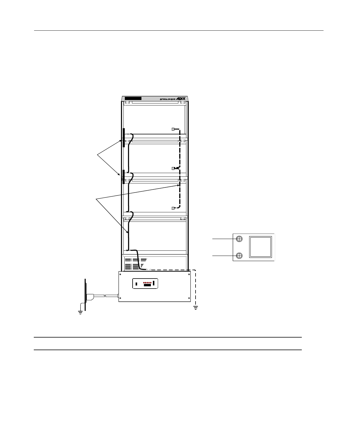
En
g
ineerin
g
Bulletin EBA-2000-28 DRAFT
64 of 105
ADIX Software Version 7.00
Installation Guide and Feature Description
Grounding the ADIX
Fi
g
ure 28 illustrates the proper
g
round termination points for the
g
round straps between
the IX-CM and IX-EXPM units and the earth
g
round conductor attached to the power sup-
ply.
Figure 29. ADIX SYSTEM GROUNDING
Note: A separate
g
roundin
g
conductor must be run if the AC outlet
g
round is not effective.
Ground
Wire
Ground
Bar
Earth
Ground
Commercial
Ground
DCDC LNK OPT CPU HWC SIF 1 2 3 4
DCDC 1 2 3 4 5 6 7 8
DCDC 1 2 3 4 5 6 7 8
DCDC 1 2 3 4 5 6 7 8
CN1TG
To Ground
Bus
To Earth
Ground
Po w e r S u p p l y
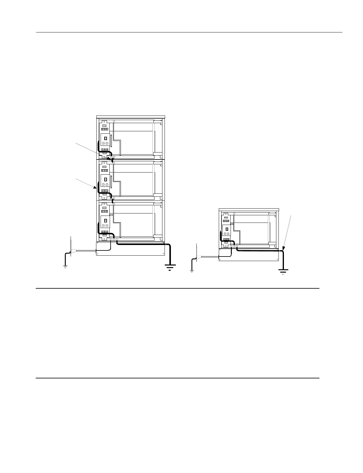
En
g
ineerin
g
Bulletin EBA-2000-28 DRAFT
65 of 105
ADIX Software Version 7.00
Installation Guide and Feature Description
Grounding the ADIX-S and ADIX-M
Fi
g
ure 29 illustrates the proper
g
round termination points for
g
round straps between the
IX-CMM and IX-EXPMM units and the earth
g
round conductor attached to each power
supply. Groundin
g
must comply with the
g
eneral rules for
g
roundin
g
contained in Article
250 of the National Electrical Code, NFPA 70, and Article 607 of the TIA/ EIA Standard.
Figure 30. ADIX-S/M SYSTEM GROUNDING
Note:
A separate
g
roundin
g
conductor must be run if the AC outlet
g
round is not effective. If it is deter-
mined that a separate
g
roundin
g
conductor is required, precautions must be taken throu
g
h volta
g
e
and current measurements that a
g
round loop condition does not exist between the electrical
g
round and the earth
g
round conductor. Also consider the followin
g
:
1. An external
g
round conductor should always be considered when usin
g
g
round start trunks.
2. An external
g
round conductor should always be considered when the system is installed in an
environment that is likely to have hi
g
h RF or EMI density. For example, near a radio stations
with a local transmitter.
3. The use of a cold water pipe as a
g
round is not permitted by some utilities and facilities. Check
with your local utility or buildin
g
mana
g
er before usin
g
a cold water pipe as a
g
round.
ΓΝ∆
AC
Outlet
Grounding
Wire
Commercial
Ground Earth
Ground
AC
Outlet
Grounding
Wire
Commercial
Ground
Earth
Ground
GND
GND
GND
Po w e r
Supply
Grounding
Wire
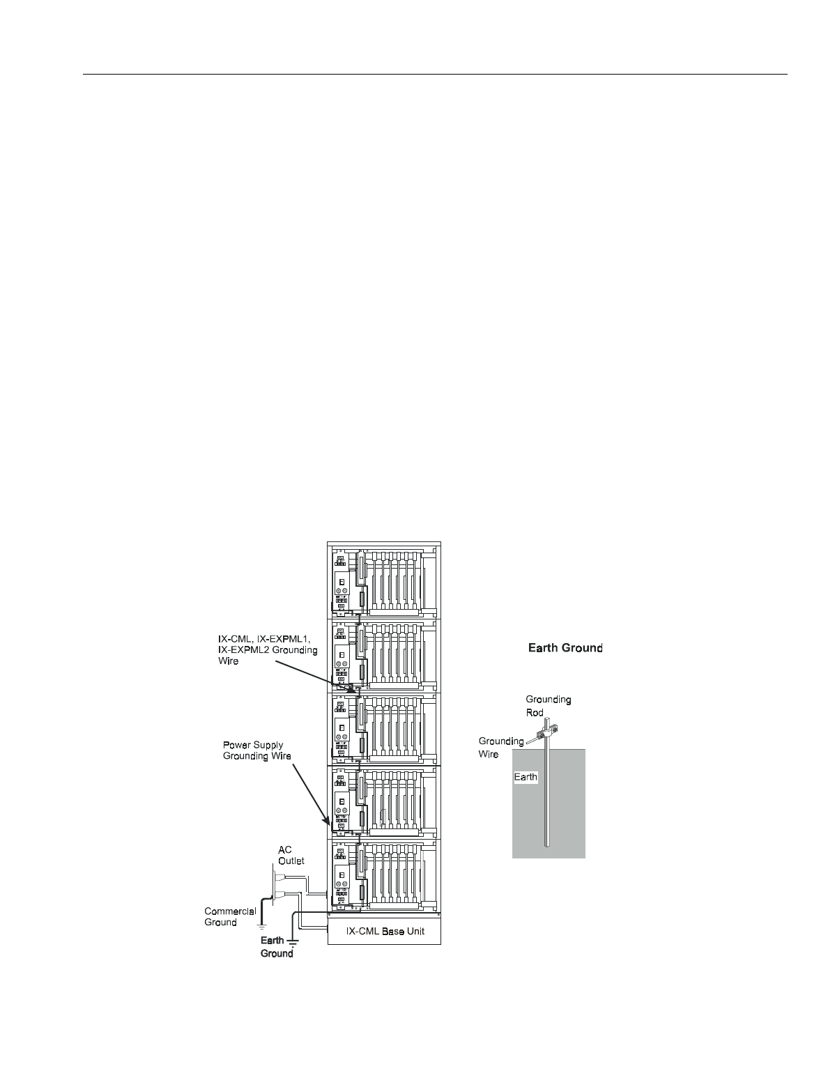
En
g
ineerin
g
Bulletin EBA-2000-28 DRAFT
66 of 105
ADIX Software Version 7.00
Installation Guide and Feature Description
Grounding the ADIX APS
The
g
round conductor of the AC Power Cord is to be secured on the bottom of the Com-
mon Module frame as illustrated in Fi
g
ure 30. Groundin
g
must comply with the
g
eneral
rules for
g
roundin
g
contained in Article 250 of the National Electrical Code, NFPA 70, and
Article 607 of the TIA/ EIA Standard.
The
g
round conductor is to be secured on the bottom of the IX-CML Common Module
frame as illustrated in Fi
g
ure 30. The opposite end of the
g
round conductor must be
bonded to an effective earth
g
round potential as illustrated in Fi
g
ure 30. The conductor
must be bonded to an earth
g
round rod of a known potential.
When one or more IX-EXPML units are added to the IX-CML, the
g
round connectin
g
jumper wire that is provided with the IX-EXPML must be used. The
g
round connectin
g
jumper wire provides continuity from the frame of the IX-CML to the frame of each IX-
EXPML. Ground wires must be connected individually to the
g
round screws on each IX-
CML common module, IX-EXPML1 and IX-EXPML2 expansion module.
If the
g
round wires are joined at any point, instead of bein
g
secured separately, their com-
mon impedance will render the
g
roundin
g
less effective a
g
ainst interference.
Fi
g
ure 30 illustrates the proper
g
round termination points for
g
round straps between the
IX-CML common module, IX-EXPML1 and IX-EXPML2 expansion modules and the earth
g
round conductor attached to each power supply.
Figure 31. ADIX APS Grounding
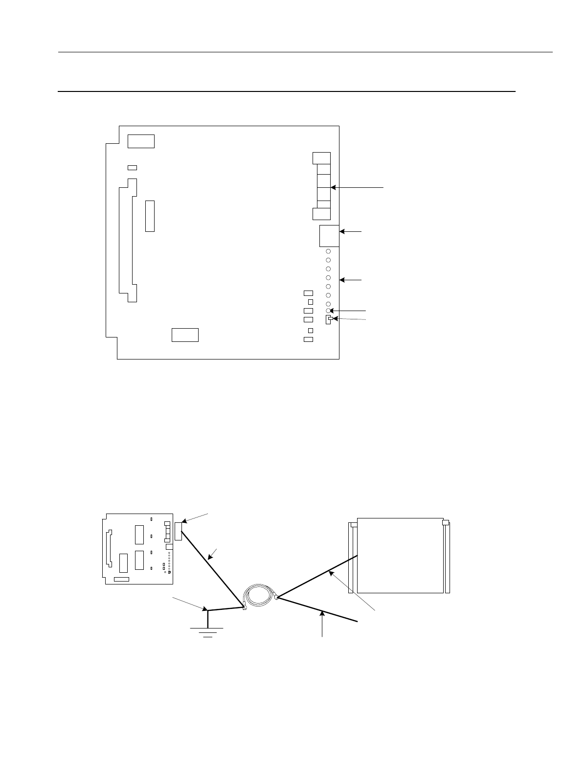
En
g
ineerin
g
Bulletin EBA-2000-28 DRAFT
67 of 105
ADIX Software Version 7.00
Installation Guide and Feature Description
Configuring the IX-4CSUB-3 Card
Figure 32. IX-CSUB-3 Card
1. Turn Switch DSW1 positions 3 & 8 on. For dual hi
g
hway installations, also turn on position 7.
Turn DSW1 position 7 off if you are installin
g
the IX-CSUB-3 card into a sin
g
le hi
g
hway slot.
2. Cut the jumper wires to match the power supplied to the IX-BS5 base stations.
3. The shielded wires on the ADIX end are connected to the frame
g
round throu
g
h the IX-
4CSUB-3 card. Cut the shielded wires on the base station end to the ed
g
e and leave them
open.
Figure 33. Cutting and Connecting Shielded Wires
Quick Connector for Base
Stations
Connector for Personal Computer
Operation Indicator LEDs
Make Busy Switch
Make Busy LED
CSMP
CSMP
B1
DSW1
SW1
BCONN
CCONN
IX-4CSUB-3
FMW
JP2
JP1
Cat 5 Cable
IX-4CSUB-3
Quick Connector
Signal and Power Feed Lines
Frame Ground
Shielded Wires
Shielded Wires
Signal and Power Feed Lines
IX-BS5
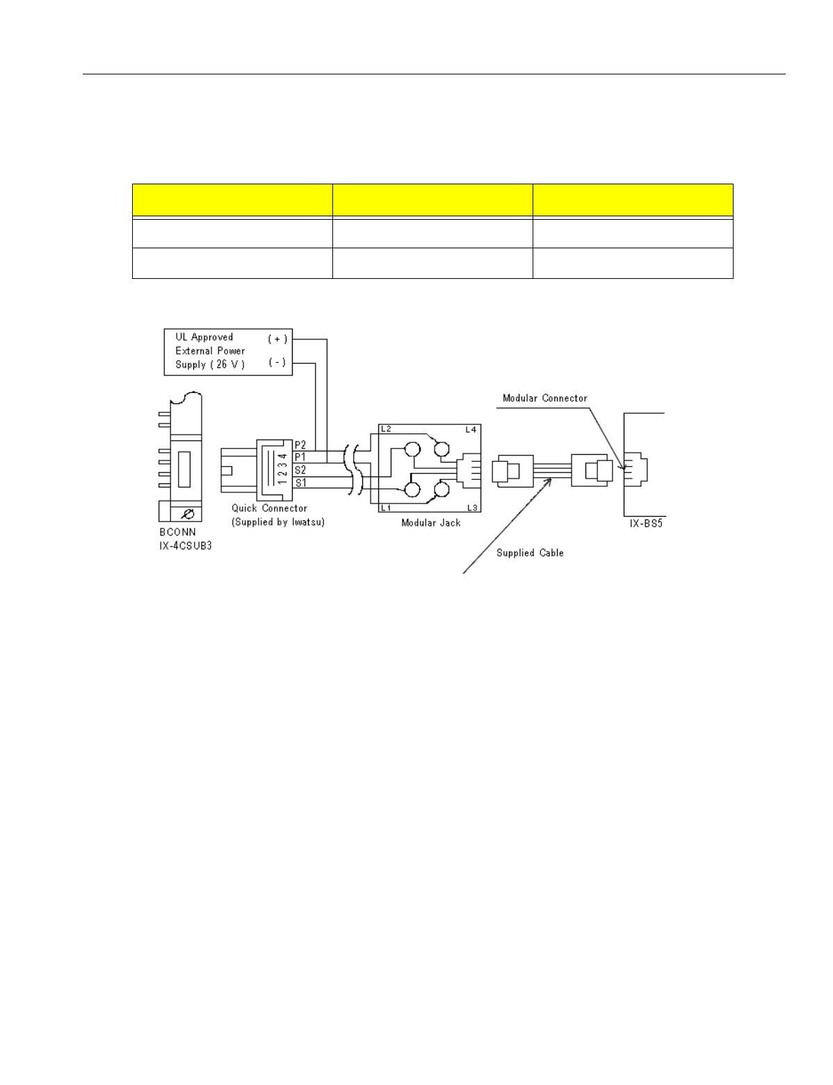
En
g
ineerin
g
Bulletin EBA-2000-28 DRAFT
68 of 105
ADIX Software Version 7.00
Installation Guide and Feature Description
4. Thou
g
h the ADIX normally supplies -26 V to the IX-BS5 base station, the IX-4CSUB-3 card
provides an external power source to it in case the ADIX APS needs an additional power sup-
ply. In order for the IX-4CSUB-3 card to supply -26 V to the base station externally, modify the
settin
g
s of the strappin
g
jacks J1 and J2 and jumpers J401 and J402 on the IX-4CSUB-3 card.
Figure 34. Connecting a Base Station with External Power Supply
Strapping Jack / Jumper Internal Power External Power
Jacks J1 and J2 Open Closed
Jumpers J401 and J402 Closed Open
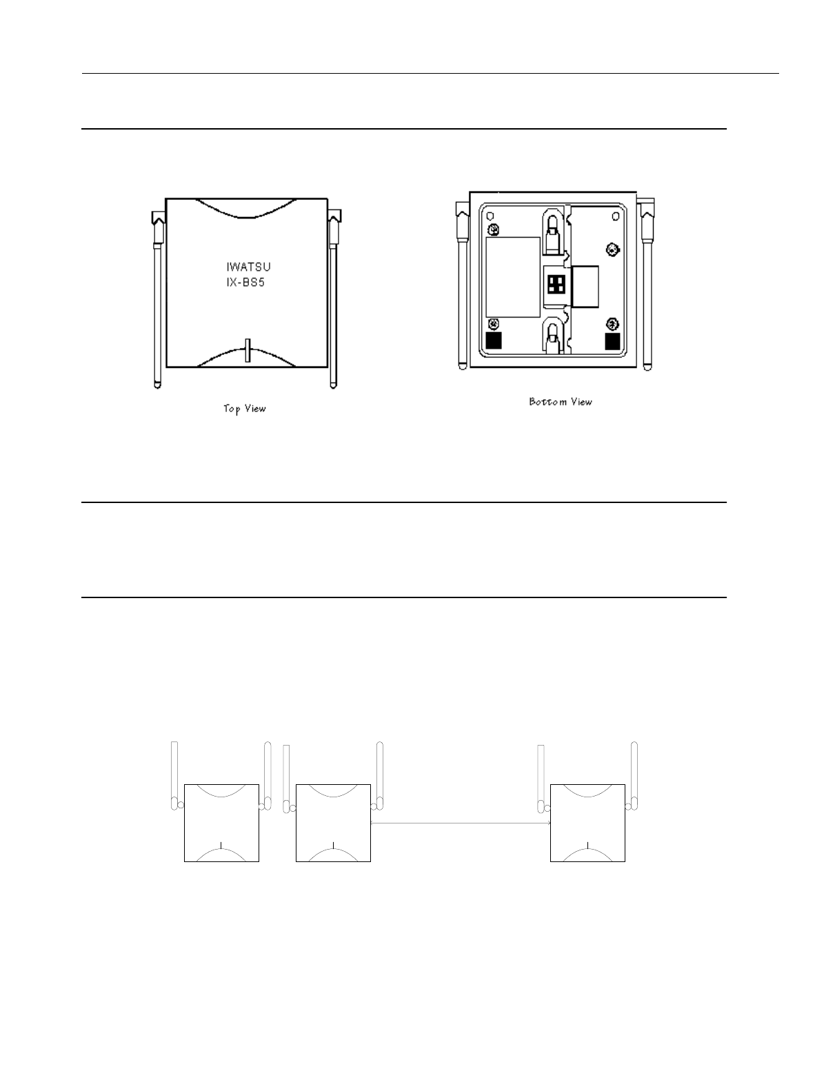
En
g
ineerin
g
Bulletin EBA-2000-28 DRAFT
69 of 105
ADIX Software Version 7.00
Installation Guide and Feature Description
Configuring the IX-BS5 Base Station
Use the IX-BS5 base station only with the IX-4CSUB-3 card.
Figure 35. IX-BS5 Base Station Top and Bottom Views
Installation Conditions
CAUTION
The IX-BS5 has been certified as a mobile device as per FCC Section 2.1091. In order to compl
y
with the FCC RF exposure requirements, the IX-BS5 must onl
y
be installed with approved antennas
and a minimum separation distance of 18 inches must be maintained from the antenna to an
y
nearb
y
people.
•Each IX-BS5 base station should be placed at least ten feet from the usual locations of IX-PS6
portable stations.
•Base stations in the same cell should be placed approximately four feet from one another.
They must be placed at least 3.3 feet apart in order to comply with FCC Part 15 re
g
ulations for
Ome
g
atrek.
•Base stations should be placed at least thirty-three feet away from base stations in other cells.
Figure 36. Base Station Placement in Relation to Cells
•When usin
g
two or more base stations in a cell,
g
ive the primary and secondary base stations
the same ID before connectin
g
them to the same IX-4CSUB-3 card.
•You can connect one primary base station and up to three secondary base stations to one IX-
4CSUB-3 card.
IWATSU
IX-BS5
IWATSU
IX-BS5
At least 33 feet
IWATSU
IX-BS5
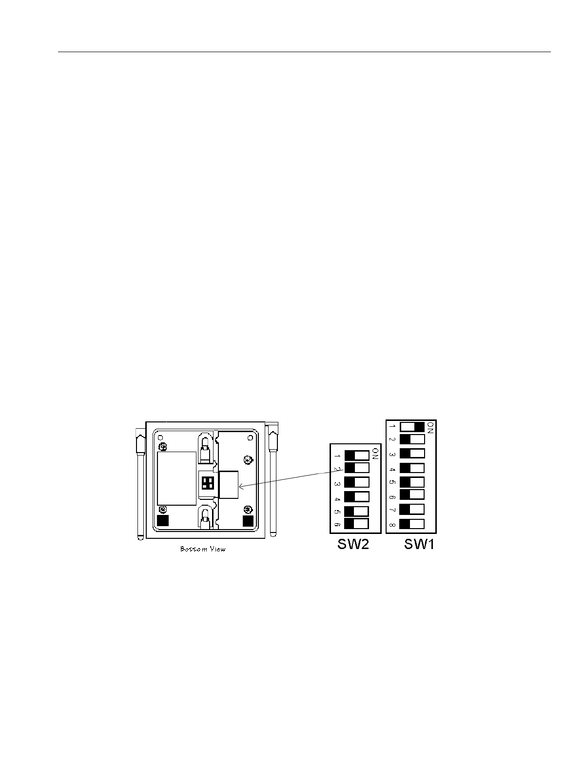
En
g
ineerin
g
Bulletin EBA-2000-28 DRAFT
70 of 105
ADIX Software Version 7.00
Installation Guide and Feature Description
•Up to 32 portable stations per primary base station can be in stand-by mode at one time, but
that number should be kept to fewer than sixteen due to shared resources issues.
•The number of portable stations with simultaneous key lamp indication chan
g
es on their indi-
vidual keys should be kept to four or fewer due to system speed issues. The last portable sta-
tion to have a lamp indication chan
g
e is about 1.5 seconds later than the first one.
•Includin
g
many cells in one main cell
g
roup is not recommended. Keep the number of primary
base stations per main cell
g
roup to 10 or fewer.Notification si
g
nals may be delayed if many
incomin
g
calls are received at the same time.
Configuration Procedures
1. Determine the number and placement of primary base stations and secondary base stations
after you have established the number of portable stations, the number of simultaneous con-
versations needed, and the location of your cells.
2. Remove the plastic tabbed plate from the bottom ri
g
ht of the IX-BS5. See Fi
g
ure 36.
3. Set the base station ID switches usin
g
the SW1 and SW2 [1-5] DIP switches. Primary base
stations in cells have unique primary base station IDs that are numbered from 1 to 108.
4. Set the operation mode as either primary or secondary usin
g
SW2 [6].
•To make the base station a primary base station, set switch SW2 [6] to OFF. The primary
settin
g
is the default settin
g
for this switch. Because a primary base station transmits and
receives control information on the control channel, three voice channels are available.
There should be one primary base station in each cell.
•To make the base station a secondary base station, set switch SW2 [6] ON. Four voice
channels are available for a secondary base station. Up to three base stations can be sec-
ondary base stations in a cell. These secondary base stations are connected to the same
IX-4CSUB-3 card to which the primary base station is connected.
Figure 37. IX-BS5 Base Station Switch Settings
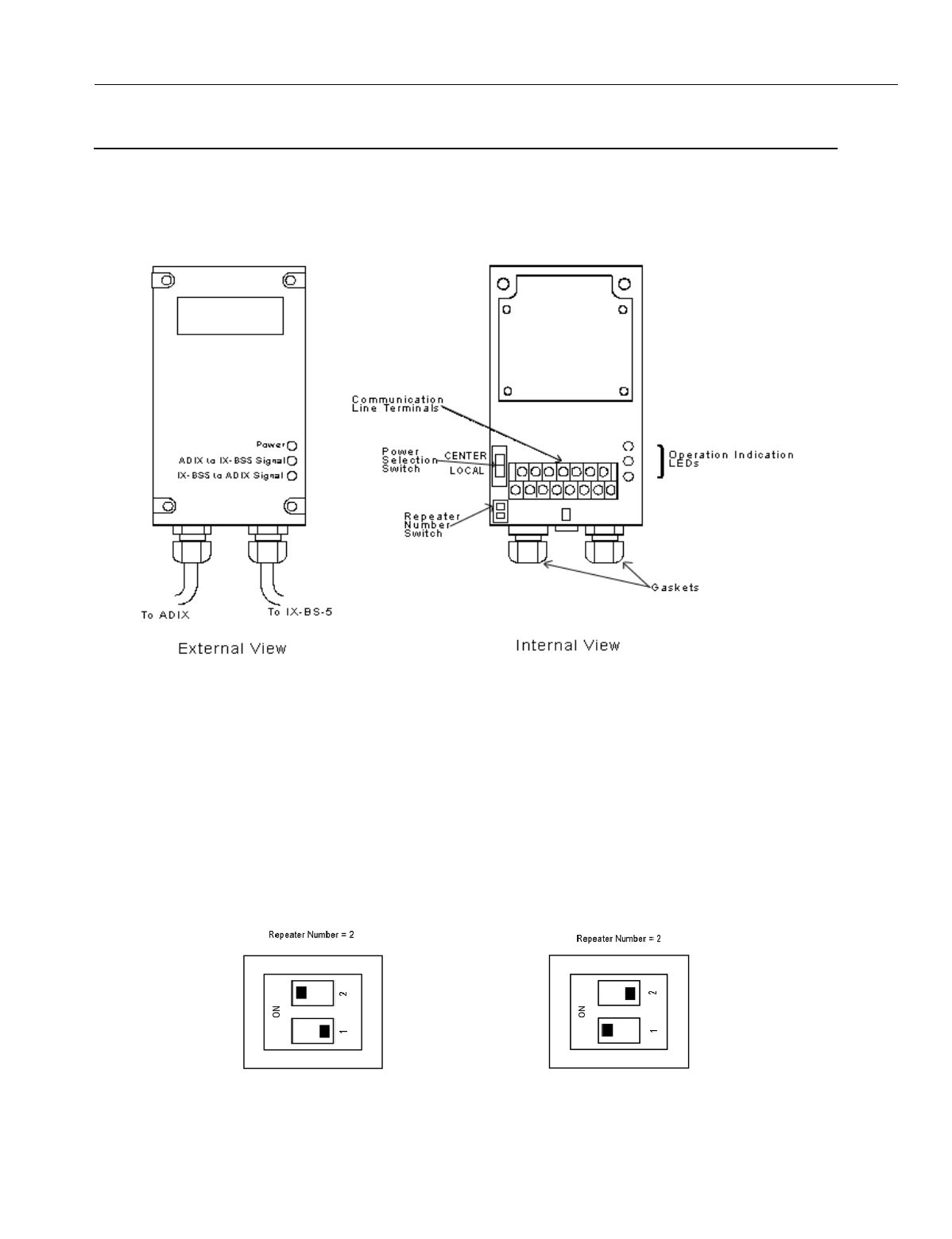
En
g
ineerin
g
Bulletin EBA-2000-28 DRAFT
71 of 105
ADIX Software Version 7.00
Installation Guide and Feature Description
Configuring the IX-BSREP Repeater
Repeaters are used to extend the distance that a radio si
g
nal can travel between the
ADIX APS and a base station.
Figure 38.IX-BSREP Repeater
Configuration Procedure
1. Use a Phillips head screwdriver to remove the bottom of the IX-BSREP.
1. Set the repeater number switch to either 1 or 2.
•If one repeater is used for a base station, set the repeater number to 1.
•If two repeaters are used for a base station, set the repeater number of the one closer to
the ADIX APS to 1, and set the repeater number of the one closer to the base station to 2.
Figure 39. Repeater Number Settings
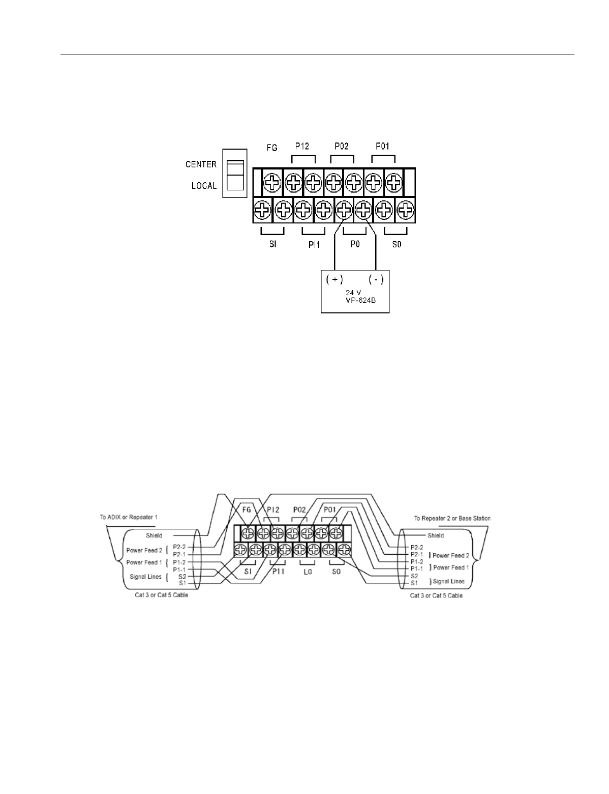
En
g
ineerin
g
Bulletin EBA-2000-28 DRAFT
72 of 105
ADIX Software Version 7.00
Installation Guide and Feature Description
2. Set the power selection switch to LOCAL.
3. Attach a Valcom VP-624B local power supply unit to the terminal pair L0 as shown below.
The VP-624B is a receptacle mount power supply desi
g
ned to be used with a third wire
g
rounded receptacle.
Figure 40. Power Supply Connection
4. Connect earth
g
round to a local
g
round screw terminal usin
g
14AWG
g
round wire. Use this
item only with a duplex receptacle equipped with a cernterscrew.The polarity does not matter.
5. Leave the terminal pairs PI1 and PI2 (used to connect a power source from the ADIX APS)
open.
6. The cable len
g
th between the VP-624B and the IX-BSREP should not exceed ten feet. Use
only cables made with UL-reco
g
nized wire rod with VW-1 markin
g
.
7. Secure the Valcom VP-624B unit usin
g
the receptacle cover screw.
8. Connect the communication line terminals. Pull the cables throu
g
h a
g
asket and cap, then turn
the cap to ti
g
hten the cables. Connect the cables to the terminals as shown below.
Figure 41.Communication Line Connection
9. Connect the external power line.
10. Check the Operation Indicator LEDs
•The Power LED li
g
hts when power is supplied.
•The ADIX to IX-BS5 LED li
g
hts when the data transmission from the ADIX APS is normal.
•The IX-BS5 to ADIX LED li
g
hts when the data transmission from the base station is nor-
mal.

En
g
ineerin
g
Bulletin EBA-2000-28 DRAFT
73 of 105
ADIX Software Version 7.00
Installation Guide and Feature Description
IX-PS6 Portable Station Configuration
Portable Station Installation Conditions
•Up to 96 portable stations per IX-4CSUB-3 card can be in stand-by mode at once.
•Up to 32 portable stations per primary base station can be in stand-by mode at once.
•The number of portable stations in the stand-by mode per primary base station should be kept
to 16 or fewer.
•The number of portable stations with simultaneous key lamp indication chan
g
es on their indi-
vidual keys should be kept to 4 or fewer. The last portable station to have a lamp indication
chan
g
e is about 1.5 seconds later than the first one. This restrictions on varies dependin
g
upon with whether key lamp indications chan
g
e on multiple portable stations and how often
chan
g
es are made.
•The total number of individual keys on the portable stations in the standby mode per primary
base station should be kept to 64 or fewer.
Maintenance Mode
Ome
g
atrek has a maintenance mode that can display the associated base station, mea-
sure the EMF stren
g
th and show frame error rate. These features are very helpful durin
g
the installation process to determine locations of the base stations.
To enter the maintenance mode before you turn the portable station on, hold the [Feat]
and [2] key and the press the [Power] key. When the station is on, you can use the fol-
lowin
g
features:
•To measure receive level and frame error rate (FER), press [Feat] + [1]. The receive level dis-
plays on the top line of the portable station’s LCD, and the frame error rate displays on the bot-
tom line.
•To display the carrier number and slot number, press [Feat] + [2]. The carrier number displays
on the top line of the portable station’s LCD, and the slot number displays on the bottom line.
•To display the cell number, press [Feat] + [3]. The cell number displays on the top line of the
portable station’s LCD.
•To display the main cell number, press [Feat] + [4]. The main cell number displays on the top
line of the portable station’s LCD.
•To display the Ome
g
atrek ID, press [Feat] + [5]. The Ome
g
atrek ID displays on the top line of
the portable station’s LCD.
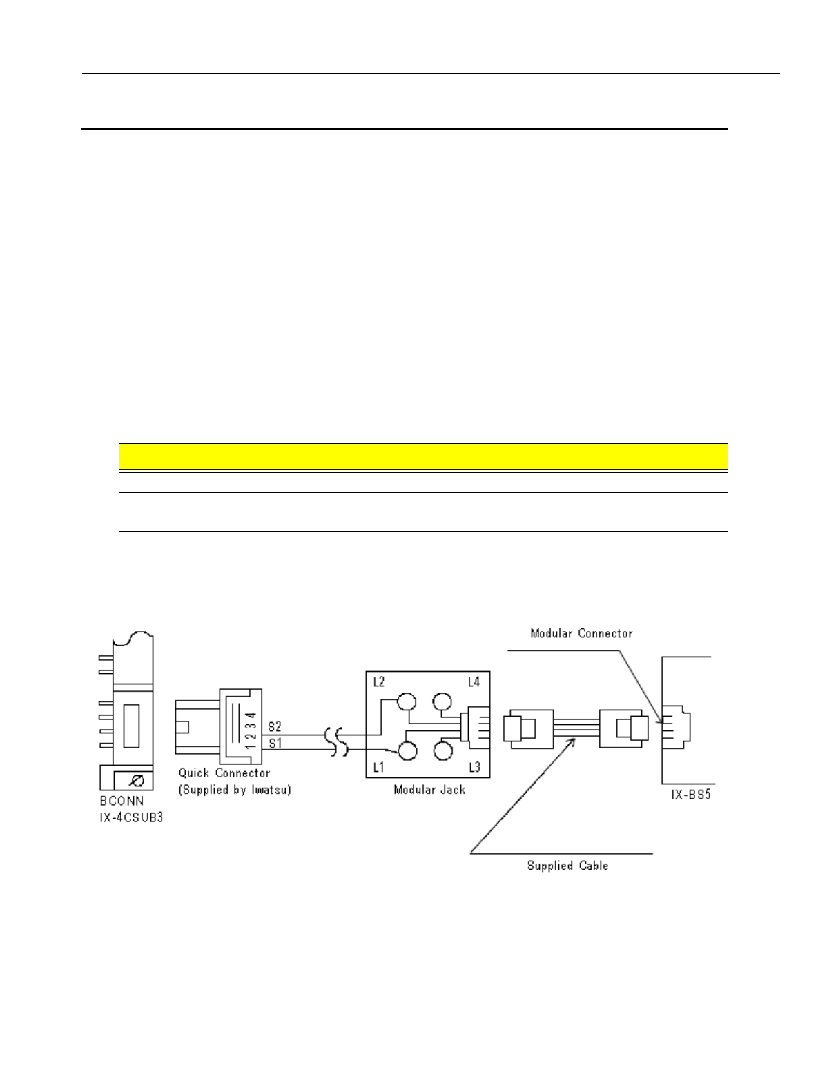
En
g
ineerin
g
Bulletin EBA-2000-28 DRAFT
74 of 105
ADIX Software Version 7.00
Installation Guide and Feature Description
Omegatrek System Installation
Installing an Omegatrek System with a New ADIX
1. Set S1, switches 6, 7, and 8 on the IX-CPUP/HW card to OFF. These switch settin
g
s must be
chan
g
ed for the Ome
g
atrek system to become functional.
2. Insert the card in a slot of the ADIX. The IX-CSUB is a 16 port card. When installin
g
the IX-
CSUB in a sin
g
le hi
g
hway slot it must be in an odd numbered slot of the hi
g
hway and the next
slot must be left open. Check the card placement information provided in the
System Plan-
nin
g
section of this manual for more information.
3. Connect IX-BS5 base stations to the BCONN connectors with cables. Connect pins 1 and 2
on IX-CSUB-3 to pins 4 and 5 of the base station.
4. Check the LED indicators on the IX-4CSUB-3 card. As you connect base stations, BS1 - BS4
LEDs on the IX-CSUB-3 card should turn on.
5. Connect the base station to the modular jack, which is connected to the ADIX APS with cable.
Use the cables specified in the table below to connect the IX-4CSUB-3 card to IX-BS5 base
stations.
6. If you are connectin
g
a base station usin
g
two pair cables, and the ADIX APS power supply to
is connected to a common external power supply, refer to Fi
g
ure 41.
Figure 42. Connecting IX-BS5 Base Station Using Two Pair Cables
7. Check the LED Indicators on the base station after the base station is connected.
•A steady red li
g
ht indicates that the connection with the ADIX APS is normal.
•A steady
g
reen li
g
ht indicates that the base station is communicatin
g
with a portable sta-
tion.
Item Condition Remarks
Cable Type 0.5 mm or more in diameter Cat 3 or Cat 5 Cables
Shieldin
g
Use shielded cables if the len
g
th
exceeds 984 feet.
Use bundled, shielded cables
Number of Pairs in Pair
Cables
1-3 pairs (2-6 wires) Si
g
nal Lines: 1 pair
Power Feed Lines: Up to 2 pair

En
g
ineerin
g
Bulletin EBA-2000-28 DRAFT
75 of 105
ADIX Software Version 7.00
Installation Guide and Feature Description
8. Adjust the antennas on the base stations so that they point upri
g
ht. If the base station is
mounted on a wall, tilt the antennas approximately 30 de
g
rees.
9. If you default a new system at this point, the system builds wi
g
ht portable station ports auto-
matically in the slot where the IX-4CSUB-3 card is installed.
10. Set the Base Station Attributes in Class 32, Item 01, Element 1 of Database Pro
g
rammin
g
.
The Base Station Attribute number is the number that previously entered as the ID number
throu
g
h SW1 of the base station.
11. Default the ADIX system. The base station’s LED should li
g
ht up red. Each of the four
g
reen
LEDs on the IX-4CSUB-3 card should flash quickly for each base station attached to the card.
12. Re
g
ister each portable station. All portable stations must be re
g
istered before they can be
used. To complete portable station re
g
istration, complete the followin
g
steps:
•From a Pro
g
rammin
g
Telephone (SATT), press the {Idle} + [FEAT] + [#] + [1] keys. Enter
Password displays on the LCD.
•Enter the Password [5] + [6] + [2] + [2]. PS Pro
g
rammin
g
displays on the LCD.
•Enter the Pro
g
rammin
g
Level, either [0] or [2]. 0 is initial data clear; 2 is data initialization.
•Enter the Station Lo
g
ical Number, which must be entered as 3 di
g
its.
•Enter the PS Pro
g
rammin
g
Password. The Pro
g
rammin
g
Password is composed of four
di
g
its ran
g
in
g
from 0000 to 9999, and the value is not related to any other password in an
ADIX.
•Press Enter.
Enter Password
PS Programming
- -
PS Programming
2 - -
PS Programming
2 - 009 -
PS Programming
2 - 001 - 1234

En
g
ineerin
g
Bulletin EBA-2000-28 DRAFT
76 of 105
ADIX Software Version 7.00
Installation Guide and Feature Description
13. From the portable station bein
g
pro
g
rammed, complete the followin
g
steps:
•Before you can re
g
ister the portable station, it must be in the pro
g
rammin
g
mode. To enter
pro
g
rammin
g
mode, hold the [8] and [#] keys while turnin
g
the phone on. The followin
g
screen displays on the portable station’s LCD after a link is established with the pro
g
ram-
min
g
base station.
•When a link is not established with the pro
g
rammin
g
base station, the followin
g
messa
g
e
displays on the portable station.
•After a link has been established, the portable station displays a request for the system
number.
•Enter the System Number [1] - [9]. You can have up to 9 Ome
g
atrek IDs stored in a porta-
ble station. The password screen displays.
•Press the [Hold/Menu] Enter Key.
•Enter your password 0000-9999. This password is same password as set above in the
ADIX.
•Press the [Hold/Menu] Enter Key.
•After pro
g
rammin
g
is completed successfully, the followin
g
displays on the LCD.
•If the portable station’s pro
g
rammin
g
fails, the followin
g
screen displays:
PROGRAMMING
VX XX XXXX
LINK FAILED
COMPLETED
FAILED
H
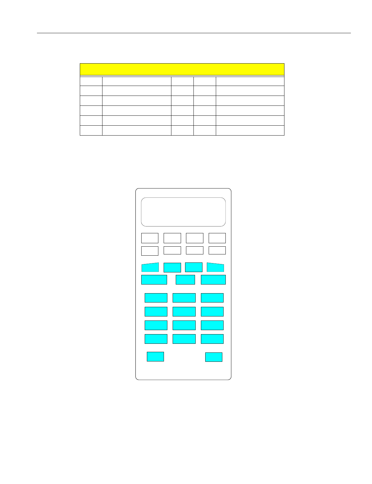
En
g
ineerin
g
Bulletin EBA-2000-28 DRAFT
77 of 105
ADIX Software Version 7.00
Installation Guide and Feature Description
•If the pro
g
rammin
g
completes successfully, the status returns to {Enter Pro
g
rammin
g
Level}. If pro
g
rammin
g
fails, an error code displays.
14. Use Class 10, Item 02 in database pro
g
rammin
g
to set the extension number for the portable
station.
15. Select the appropriate key pattern number for the Ome
g
atrek system in Classes 10 and 12 in
Database Pro
g
rammin
g
. Pattern 101 adapts for the portable station. The default key pattern
is illustrated below.
Figure 43. IX-PS6 Portable Station Default Key Pattern
16. Select Class 32, Item 04 in database pro
g
rammin
g
to set the pro
g
rammin
g
base station. If the
base station is set as lo
g
ical number 1, you need not set this item.
17. Turn on the portable station. Make sure that the antenna picto
g
ram is displayed and that the
extension number is shown on the LCD.
HH indicates error code as follows
1: SO data error 7: LCH refused
2: Time out 8: Link not established
3: Initialize error 9: Link disconnected
4: Authorization error 0: FER error
5: DL released 11: PSID not a
g
reed
6: LCH not established 2: Others
FLT0 FLT0 PAR TRA
FWD ADD MSG MUTE
DOWN
ICM Hold/DND
1
2
3
4
5
7 8 9
6
* 0 #
SPK
UP
FEAT
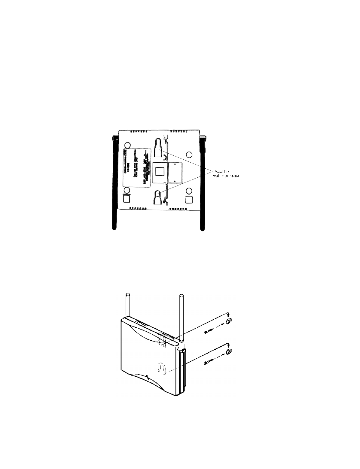
En
g
ineerin
g
Bulletin EBA-2000-28 DRAFT
78 of 105
ADIX Software Version 7.00
Installation Guide and Feature Description
Wall Mounting the Base Station
1. Determine the placement of the base station.
2. The cardboard holder used to brace the base station in its shippin
g
packa
g
e contains two
screws, two spacers, and an extra telephone line. Remove these items from the cardboard
holder.
3. If a telephone wall mountin
g
bracket exists at the installation site, remove any protrudin
g
jacks
from the bracket and secure the base station to the bracket by placin
g
the indicated indented
areas on the back of the base station to the existin
g
protrudin
g
bracket screws. Proceed to
step7.
Figure 44. Base Station Wall Mounting Holder
4. If a telephone wall mountin
g
bracket does not exist at your installation site, use the template
on the followin
g
pa
g
e to determine the screw placement on the wall. Hold the template to the
wall and use a pencil or pen to mark the wall where the screws will be inserted.
5. Use a Phillips head screwdriver to place the screw and spacer in the wall as indicated in Fi
g
-
ure 43.
Figure 45. Base Station Mounting
6. Attach the base station to the wall.
7. Tilt the antennas approximately 45 de
g
rees from upri
g
ht.

En
g
ineerin
g
Bulletin EBA-2000-28 DRAFT
79 of 105
ADIX Software Version 7.00
Installation Guide and Feature Description
Figure 46. Base Mounting Installation Template
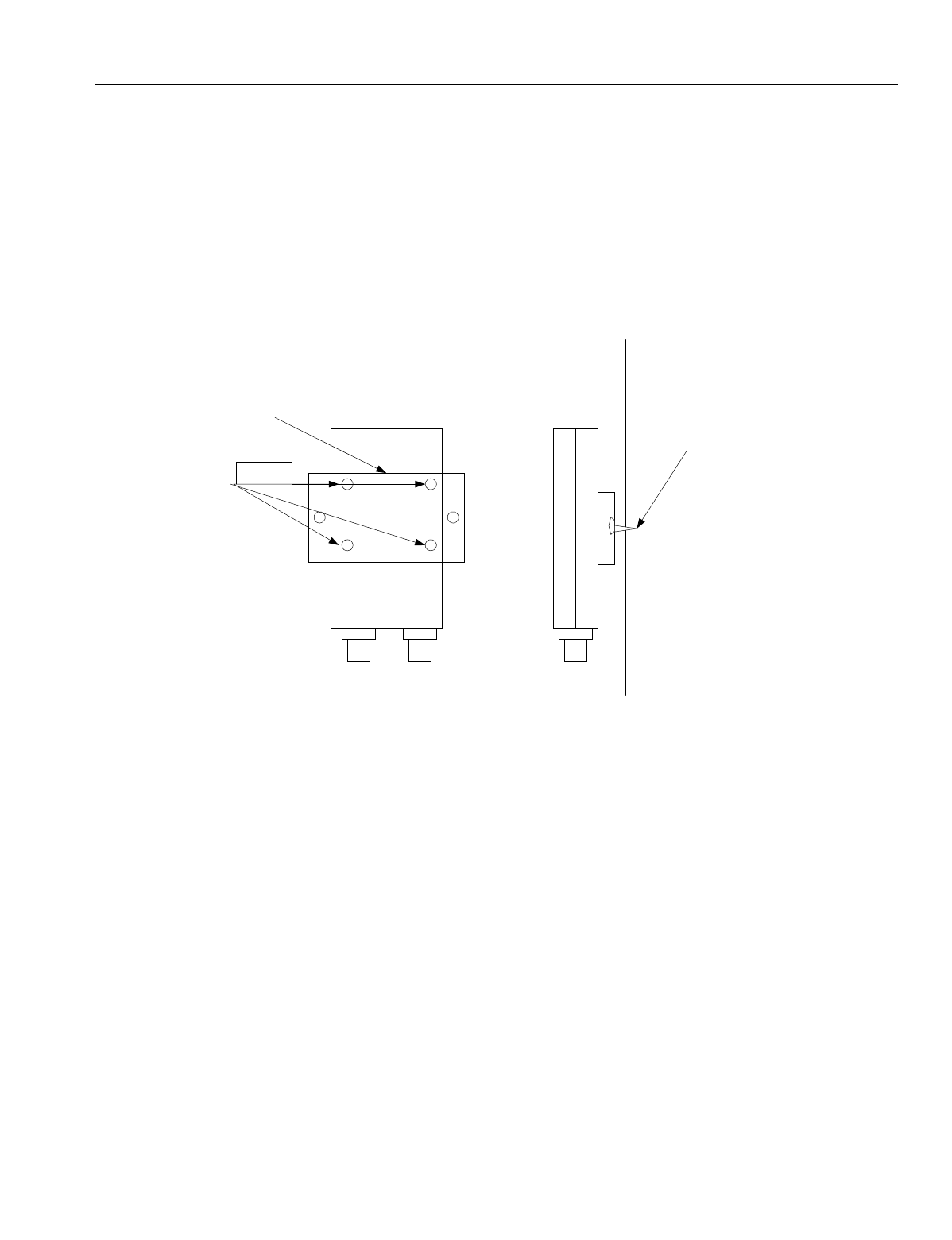
En
g
ineerin
g
Bulletin EBA-2000-28 DRAFT
80 of 105
ADIX Software Version 7.00
Installation Guide and Feature Description
Wall Mounting the IX-BSREP
The IX-BSREP packa
g
in
g
contains a mountin
g
bracket, short metal anchor screws, and
lon
g
metal anchor screws that can be used to mount the IX-BSREP unit on the wall.
To wall mount the IX-BSREP unit:
1. Use a Phillips head screwdriver to attach the metal wall mountin
g
bracket to the IX-BSREP
unit as illustrated in Fi
g
ure 45.
2. Attach the IX-BSREP and the wall mountin
g
bracket to the wall usin
g
a Phillips head screw-
driver and the lon
g
anchor screws.
Figure 47. Wall Mounting the IX-BSREP
++
++
IX-BSREP Wall Mounting
Bracket
Metal Anchor Screws
(Short)
Back View Side View
Wall
IX-BSREP Anchor Screws
(Long)
En
g
ineerin
g
Bulletin EBA-2000-28 DRAFT
81 of 105
ADIX Software Version 7.00
Installation Guide and Feature Description
Portable Station Key Assignment
To make a portable station key assi
g
nment:
1. Enter pro
g
rammin
g
mode by holdin
g
the [8] and [#] keys while turnin
g
the phone on. The fol-
lowin
g
screen displays on the portable station’s LCD after a link is established with the pro-
g
rammin
g
base station.
2. Define the key patterns in both a personal station and the system.
3. To make Key Assi
g
nments to the multipurpose keys, pro
g
ram the key patterns in Class 10.12
for each portable station.
4. Define the Key Numbers and Key Pattern Types in Class 14.01.
5. Define Group Key Assi
g
nments for each Group Call Area.
6. You can define a maximum of 127 All Call Areas in seven Group Call Areas created for each
All Call Area.
7. To make
g
roup key assi
g
nment to the flexible keys, key patterns (selected from 64 key pat-
terns) must be pro
g
rammed in Class 32.02 for each Group Call Area.
8. Define the key numbers and types of the 64 key patterns in Class 32.01.
9. When a flexible key is verified for the assi
g
ned feature ([FEAT][FEAT][#][9]), the portable sta-
tion displays the name of the feature pro
g
rammed in Key Assi
g
nment. If the key is not pro-
g
rammed with a feature in Key Assi
g
nment, the portable station displays the name of the
feature pro
g
rammed in Group Key Assi
g
nment. If no feature is pro
g
rammed to the key, the
operation is canceled.
10. Verify the status of the Ei
g
ht Line Keys (L1-L8) with the above operation.
Key Assignment Number Key Data
63 One Touch Key
64 Redial/Clear
72 Speaker
73 Shift Ri
g
ht
74 Shift Left
75 Zone
76 Mute
77 PB Dial
78 Messa
g
e Readout
79 Key Display
80 Alert Cancellation
92 Feature
93 Short Flash
94 Lon
g
Flash
95 Flash
97 Hold/Menu
98 Send Intercom
99 End/Power
PROGRAMMING
VX XX XXXX
En
g
ineerin
g
Bulletin EBA-2000-28 DRAFT
82 of 105
ADIX Software Version 7.00
Installation Guide and Feature Description
IX-PS6 Portable Station Key Labels
The portable station includes a set of adhesive labels that can be used to label assi
g
ned
keys with functions that you have pro
g
rammed. These labels include 21 clear labels with
the most common functions pre-printed and six white labels that other functions can be
written or typed on.
To use these labels:
1. If the function for which you need the label is not pre-printed, write or type the function name
on a blank label.
2. Peel the needed label from the adhesive sheet.
3. Affix the label over the key with the desi
g
nated function.
Figure 48. Adhesive Key Labels for Portable Station
LINE
UNAMICVML
GPK2GPK1FLT
DSSPAGEOUT
ADDMUTEPARK
FLSH
HUNT
FLT
OUT
TRAN
MSGFWDLINE
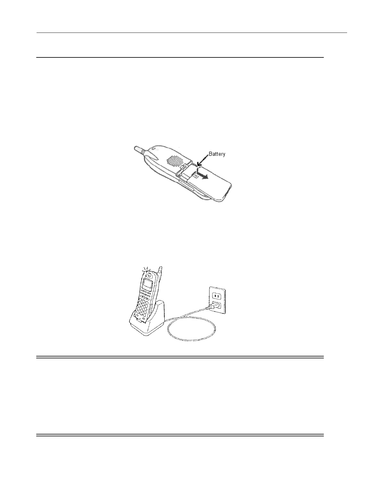
En
g
ineerin
g
Bulletin EBA-2000-28 DRAFT
83 of 105
ADIX Software Version 7.00
Installation Guide and Feature Description
IX-PS6 Portable Station Battery Installation
The life of the battery in the IX-PS6 portable station varies with usa
g
e, but is
g
enerally
about one year. If the battery cannot be rechar
g
ed by the battery char
g
er included with
the portable station, or if it drains quickly after a full rechar
g
e, it should be replaced with a
new battery.
To install a new battery in a portable station:
1. If the portable station is ON, press and hold the Power key for more than one second to turn it
OFF.
2. Remove the battery cover.
Figure 49. Battery Removal
3. Unplu
g
the connector and remove the old battery.
4. Plu
g
the new battery into the connector and place the battery snu
g
ly into the compartment.
5. Replace the battery cover.
6. Put the portable station on the char
g
er and char
g
e the battery for more than seven hours.
Figure 50. Charging the IX-PS6
WARNINGS
Make sure the portable station is OFF before replac-
ing the battery.
Do not use any battery charger other than the one
included with the portable station
Keep the battery away from fire. Do not overheat the
battery.
Do not use any battery other than those manufac-
tured for the portable station.

En
g
ineerin
g
Bulletin EBA-2000-28 DRAFT
84 of 105
ADIX Software Version 7.00
Installation Guide and Feature Description
Troubleshooting and Setup Verification
Troubleshooting the Omegatrek System
This section details some of the most common problems encountered durin
g
the Ome
g
a-
trek installation process describes how to solve some major issue for the installation.
Problem Solution
Some portable stations are not
functionin
g
.
Check the number of lines bein
g
used simultaneously in the
portable stations’ cell
g
roup. Primary base stations have
three lines available, and each secondary base station in
the cell adds four lines to the total lines available. If you
have a primary base station with one secondary base sta-
tion in a cell, and seven portable stations are in use, and
ei
g
hth base station will not function in that cell.
A base station does not work prop-
erly or is not functionin
g
.
Check the distance between each base station. Base sta-
tions must be placed at least four feet away from each other
in order to avoid problems with cross modulation.
Portable stations are not receivin
g
si
g
nal at a distance smaller than
the portable station/base station
limit stated in this document.
As a
g
eneral rule, a portable station should be able to
receive transmissions from a base station at a distance of
300 feet. However, an office environment can affect the dis-
tance that a si
g
nal can reach due to fluctuations of electro-
ma
g
netic waves.
A portable station near a base sta-
tion is often receivin
g
a channel
with inferior voice quality.
If the base station that the portable station is near is busy,
the portable station will use any available base station, even
if the base station that it will use is a lar
g
er distance away
than desired.
Transmissions from portable sta-
tions to other portable stations are
unstable.
If there are multiple ADIX systems installed near one
another, instability in portable station transmissions may
result.
The LED on the surface of BS
doesn't appear as solid red.
Make sure that the connectin
g
cable connects from S1on
the quick connector to L1 in the module connector and that
S2 from the quick connector connects to L2 in the module
connector.
Use another cable.
The OPE LED (the top one) doesn't
li
g
ht solid
g
reen or the ALM lamp
(the second one) li
g
hts solid red.
Confirm that the IX-4CSUB-3 DSW is set properly. 3 and 8
should be ON if you are usin
g
a sin
g
le hi
g
hway, and 3, 7,
and 8 should be ON if you are usin
g
a double hi
g
hway. All
other switches should be set to OFF.
Switches 6,7 and 8 in S1 on the IX-CPUP/HW card must be
set to OFF.

En
g
ineerin
g
Bulletin EBA-2000-28 DRAFT
85 of 105
ADIX Software Version 7.00
Installation Guide and Feature Description
Troubleshooting the Omegatrek System (Cont’d)
Problem Solution
BS1~BS4 LED on a IX-4CSUB-3
flashes slowly (The cycle is 0.5sec)
Check dipswitch settin
g
s on the IX-CPUP/HW and IX-
4CSUB-3 cards.
BS1~BS2 LEDs indicate the status of each IX-BS5. If an
IX-BS5 is not connected the LED doesn't appear
Confirm that the Ome
g
atrek ID is set. You can confirm it
with several tools, includin
g
PC pro
g
rammer.
Confirm the number of power downs. This number is one of
the factors used to
g
enerate the Ome
g
atrek Activation
code. Check this number usin
g
the PC Pro
g
rammer mem-
ory dump at A00CH(2byte). If this value is different from the
value used to
g
enerate the Ome
g
atrek Activation code, rec-
reate the code and upload it to the system a
g
ain. Reset the
system.
Confirm that the number of IX-BS5s connected to the sys-
tem is the same as the number used to
g
enerate the Ome-
g
atrek Activation code. If it is not, upload the number to the
system a
g
ain and perform a system reset.
Confirm that the IX-BS5 lo
g
ical numbers are set correctly
for each IX-BS5, and that none are duplicated. The number
is set usin
g
the lon
g
set of dipswitches on the bottom of
each IX-BS5. The numberin
g
functions in binary code.
Wireless pro
g
rammin
g
doesn't
work because you cannot enter the
SETTING screen.
Confirm that the IX-BS5 lo
g
ical number has been pro-
g
rammed in Class 32 Item 04. The default is 1.
Wireless pro
g
rammin
g
doesn't
work because PGT or PS display
the error messa
g
es.
Confirm that the station lo
g
ical number has been entered
from PGT.
Confirm that you used the same password (4 di
g
its)
between PGT and pro
g
rammed portable station.
Some keys on IX-PS6 (such as
[Feat]) do not work.
Confirm that key pattern 101 has been chosen as the pat-
tern for the IX-PS6

En
g
ineerin
g
Bulletin EBA-2000-28 DRAFT
86 of 105
ADIX Software Version 7.00
Installation Guide and Feature Description
IX-4CSUB Operation Indicator LEDs
Portable Station LEDs
Name of LED Indicated Pattern Status
OPE Slow flashin
g
(0.5sec ON/0.5sec OFF)
In the process of turnin
g
ON
Stable ON Workin
g
ALM Slow flashin
g
(0.5sec ON/0.5sec OFF)
Problem with CSSP
Stable ON Problem with one or more base station(s)
BS1~BS4 Moderate flashin
g
(0.3sec ON/0.2sec OFF
Base station has been removed
Slow flashin
g
(0.5sec ON/0.5sec OFF)
Base station is not operational due to problem
Stable OFF Base station is not connected
Anomalous flashin
g
(0.1sec ON/0.9 OFF)
Primary base station works but is not used
Anomalous flashin
g
(0.1sec ON/0.1sec OFF/0.1
sec ON/1.7 sec OFF)
Secondary base station works but is not used
Stable ON Base station is in use
BSY Fast flashin
g
(0.1sec ON/0.1
sec OFF0)
Make busy state
Stable ON Busy state
RUN Stable ON Runnin
g
under hi
g
h traffic situation
Type Light Pattern Status
Line Keys
(Backli
g
ht)
Two Quick Blinks While ON (Green) Your portable station is in use.
ON (Red) Another portable station in the
g
roup is in use.
Flashin
g
(Red) Your portable station is receivin
g
a call.
Slow Flashin
g
(Red) A call is on hold on another extension.
Slow Flashin
g
(Green) A call is on hold on your extension.
Dial Pad
(Backli
g
ht)
ON (Green) You are operatin
g
the dial pad keys.
Incomin
g
Call/
Char
g
e
Lamp
ON (Green) The battery is almost fully char
g
ed.
ON (Red) The battery is bein
g
rechar
g
ed.
Slow Flashin
g
(Red) Your battery cannot be rechar
g
ed.
Flashin
g
(Red) Your portable station is receivin
g
a call.

En
g
ineerin
g
Bulletin EBA-2000-28 DRAFT
87 of 105
ADIX Software Version 7.00
Installation Guide and Feature Description
Database Pro
g
rammin
g
Guide
Class 01
Class.Item Description Change Function
01.03<TRKLxxx-3> Wireless Definition New Definition
01.03<TRKLxxx-3> Ome
g
atrek ID New Item
01.06 No. of System Station Ports
Class 04
Class.Item Description Change Function
04.70.01 Redirected Number Routin
g
New Item
Class 08
Class.Item Description Change Function
08.05 Group # (1-60) Dial All Rin
g
Group New Value
Class 32
Class.Item Description Change Function
32.01 Base Station Attribution New Class and Item
32.02 Base Station Type New Class and Item
32.03 Rin
g
Response Timeout New Class and Item
32.04 Pro
g
rammin
g
Base Station New Class and Item
32.05 Reorder Tone Duration New Class and Item
32.06 Main Cell Group Tenant New Class and Item
32.07 Rin
g
Retry Timer New Class and Item
32.08 Common Key Pattern New Class and Item
Class 33
Class.Item Description Change Function
33.01 Common Key Assi
g
nment New Class and Item
Class 34
Class.Item Description Change Function
34.01 Portable Station ID New Class and Item
34.02 Cell Group Tenant Number New Class and Item
34.03 Common Key Pattern New Class and Item
34.04 Echo Suppressor New Class and Item

En
g
ineerin
g
Bulletin EBA-2000-28 DRAFT
88 of 105
ADIX Software Version 7.00
Installation Guide and Feature Description
Port Definition Class 01
Item 03
Class 01 Item 03 - Port Definition is used to define the type of terminal attached to each
physical port and to assi
g
n a lo
g
ical number to the IX-PS6 portable station.
Each portable station installed in the system must be associated with a unique physical
port in the system. This physical port may reference a card slot with an IX-4CSUB-3
installed or any open card slot in the system. In Class 01.03, every Ome
g
atrek IX-PS6
portable station must be assi
g
ned a lo
g
ical port number.
Card slots in which IX-4CSUB-3 cards are installed default with ei
g
ht ports assi
g
ned as
data=0-7-2 wireless station.
DSS Display
Programming Field Description
Related Databases:
Associated: 01.06 Station Size
Hardware Required:
IX-4CSUB-3, IX-BS5
Class/Item Element Field Description Data Field
01.03 <PRT097> Port Definition 0-7-2-097
Data Field 1: Meanin
g
: Port Classification
Ran
g
e: 0 = Station
Data Field 2: Meanin
g
: Station Type
Ran
g
e: 7 = Wireless Station
Data Field 3: Meanin
g
:Port Detail
Ran
g
e: 2 = PS-KT
Data Field 4: Meanin
g
:Lo
g
ical Port Number
Ran
g
e: 001 - 448

En
g
ineerin
g
Bulletin EBA-2000-28 DRAFT
89 of 105
ADIX Software Version 7.00
Installation Guide and Feature Description
System Station Ports Class 01
Item 06
Class 01 Item 08 - System Station Ports is used to record the maximum number of sta-
tion lo
g
ical ports available to the system. The value displayed in the data field is entered
automatically at the time of system default.
In order to expand the maximum number of station ports after system default, pro
g
ram
the Class 01.06 data field to equal the previous number of station ports plus the number
of station ports bein
g
added.
A reset is required to effect any chan
g
es pro
g
rammed in Class 01.06.
DSS Display
Programming Field Description
Related Databases:
Required: None.
Associated: 01.03 Port Definition; 01.04 Port Confi
g
uration;. 01.07 Number of System
Trunk Ports
Related Operation:
System Reset.
Related Hardware:
IX-POMT (Power-On Maintenance Tool)
Class/Item Element Field Description Data Field
01.06 Station Number 123456789
Data Field: Meanin
g
Total number of station ports available in the system.
Ran
g
e: 0 - 400 Dependin
g
upon system size
Default: Varies dependin
g
on the number of station cards ini-
tially installed.

En
g
ineerin
g
Bulletin EBA-2000-28 DRAFT
90 of 105
ADIX Software Version 7.00
Installation Guide and Feature Description
Omegatrek ID Class 01
Item 08
Class 01 Item 08 - Ome
g
atrek ID is used to reference the unique Ome
g
atrek ID to the
ADIX. This number is required to calculate the UTAM code for the wireless phones durin
g
initial installation or a system shutdown lastin
g
over six hours.
The Ome
g
atrek ID is assi
g
ned by the Iwatsu America repair department and identifies the
system for Iwatsu America. Dealers may view the Ome
g
atrek ID in order for the num-
ber’s use as an Ome
g
atrek Activation Code, but they cannot chan
g
e the number.
DSS Display
Programming Field Description
Related Database:
32.02 Base Station Type
Related Hardware:
IX-PS6 Portable Station
Class/Item Element Field Description Data Field
01.08 Ome
g
atrek ID 123456789
Data Field: Ran
g
e: 000000001 - 999999999
Default: None

En
g
ineerin
g
Bulletin EBA-2000-28 DRAFT
91 of 105
ADIX Software Version 7.00
Installation Guide and Feature Description
Redirected Number Routing Class 04
Item 70
Class 04 Item 70 - Redirected Number Routin
g
is used to chan
g
e the routin
g
in Class
25 from DNIS to RNI. The ADIX uses the RNI for routin
g
instead of DNIS with both BRI
and PRI lines.
The RNI (Redirected Number) is the directory number of forwardin
g
party. This number is
used by answerin
g
services to determine where the call was forwarded from. This allows
the customer to ID the call with out havin
g
to purchase DID numbers for each client. If
an RNI is not in the setup message, the DNIS is used for routing.
When the RNI routin
g
is enabled, all displays of the DNIS number are replaced with the
RNI. This replacement includes Voice Mail packets, ACD event stream and the CSTA out-
put.
DSS Display
Programming Field Description
Related Database:
25.01 DNIS Incomin
g
Number; 25.02 DNIS Conversion Number; 25.03 DNIS Number ID;
25.05 DNIS Conversion Di
g
its; 25.06 DNIS Conversion Startin
g
Position; 25.07 DNIS Enabled
ISDN Trunk
Related Operation:
DNIS Routin
g
Class/Item Element Field Description Data Field
04.70 <NUM01> Redirected Number Routin
g
0
Data Field: Meanin
g
: Time in milliseconds a one-shot relay will remain closed
durin
g
operation.
Ran
g
e: 0 - 1
0 = Disabled (DNIS)
1 = Enabled (RNI)
Default: 0

En
g
ineerin
g
Bulletin EBA-2000-28 DRAFT
92 of 105
ADIX Software Version 7.00
Installation Guide and Feature Description
All Ring Hunt Group Class 08
Item 05
Class 08 Item 05 - All Rin
g
Hunt Group is used to rin
g
a maximum of 32 phones simul-
taneously. You may choose select 2 (All) in addition to 0(Terminal) or 1(Distributed) to
select the rin
g
method for any Hunt Group.
If 2 (All) is chosen from the ran
g
e, all stations included in a Hunt Group (up to 32 sta-
tions) rin
g
simultaneously.
DSS Display
Programming Field Description
Related Database:
Required: 04.20 Elements 31-52 VSS Recordin
g
Time; 04.20 Element 59 UCD Messa
g
e
Interval; 04.20 Element 60 UCD Disconnect Timer; 04.34 UCD Answer Time;
04.71 Element 02 UCD Back Tone; 04.71 Element 05 UCD Overflow Timer;
07.02 UCD/Huntin
g
Group Access Number; 08.02 Hunt Group Station; 11.34
DIL to Hunt Group.
Associated: 01.03 Port Definition; 01.04 Port Confi
g
uration; 04.12 Camp-On Duration;
04.55 True Attendant Position; 11.26 Attendant Intercept Line.
Hardware Required:
IX-CPUL-1, IX-CPU16, IX-CPU16M, IX-CPU32, IX-MSGU, IX-CMSG-1, IX-
CMSG, IX-EMCH.
Class/Item Element Field Description Data Field
08.05 <GRP01-01> All Rin
g
Group 0
Element Field Data: Meanin
g
: Sets the Rin
g
Method of the Hunt Group
Ran
g
e: 0 - 2
0 = Terminal
1 = Distributed
2 = All Rin
g
Default: 0

En
g
ineerin
g
Bulletin EBA-2000-28 DRAFT
93 of 105
ADIX Software Version 7.00
Installation Guide and Feature Description
Base Station Attribution Class 32
Item 01
Class 32 Item 01 - BS Attribution is used to assi
g
n a primary base station to a cell
g
roup.
To optimize the si
g
nal reception, the Ome
g
atrek Wireless System is installed usin
g
a cell
confi
g
uration. A cell is the area covered by radio si
g
nals from a base station. Si
g
nal
stren
g
th in a cell should be stron
g
enou
g
h for users of the Ome
g
atrek Wireless System to
carry on normal conversations.
Each primary base station provides telephone covera
g
e for a cell. In an open area with-
out a secondary base station, a cell covers a circular area of about 328 feet from the pri-
mary base station. Realistically, radio si
g
nals can be blocked by many objects in a
normal office settin
g
, so the radius of the cell may only extend to about 165 feet in a
g
en-
eral office environment.
DSS Display
Programming Field Description
Related Databases:
32.08 Common Key Pattern; 33.01 Common Key Pattern Assi
g
nment; 34.03 Common Key
Pattern
Hardware Required:
IX-4CSUB-3
Class/Item Element Field Description Data Field
32.01 Lo
g
ical Port Number of IX-BS5
Base Station
BS Attribution 001-1-00
Element Field 1 (e1): Meanin
g
: Main Cell Group
Ran
g
e: 1 - 127
Default: 1
Element Field 2 (e2): Meanin
g
: Sub Cell Group
Ran
g
e: 1 - 8
Default: 1
Element Field 3 (e3): Meanin
g
: Cell Number
Ran
g
e: 0 - 31
Default: 0

En
g
ineerin
g
Bulletin EBA-2000-28 DRAFT
94 of 105
ADIX Software Version 7.00
Installation Guide and Feature Description
Base Station Type Class 32
Item 02
Class 32 Item 01 - Base Station Type is used to assi
g
n a unique Ome
g
atrek ID to the
ADIX. This number is used to reference the unique Ome
g
atrek ID to the ADIX. This
number is required to calculate the UTAM code for the wireless phones durin
g
initial
installation or a system shutdown lastin
g
over six hours. It must be set to 1.
The Ome
g
atrek ID is assi
g
ned by the Iwatsu America repair department and identifies the
system for Iwatsu America. Dealers may view the Ome
g
atrek ID in order for the num-
ber’s use as an Ome
g
atrek Activation Code, but they cannot chan
g
e the number.
WARNING
Even though this item’s range is from
1 to 3, the value of this field MUST be
set to 3.
DSS Display
Programming Field Description
Related Database:
01.08 Ome
g
atrek ID
Class/Item Element Field Description Data Field
32.01 <NUM001> Base Station Type 3
Data Field: Meanin
g
: Sets the type of the base station
Ran
g
e: 1-3
Default: 1

En
g
ineerin
g
Bulletin EBA-2000-28 DRAFT
95 of 105
ADIX Software Version 7.00
Installation Guide and Feature Description
Ring Response Timeout Class 32
Item 03
Class 32 Item 03 - Rin
g
Response Timeout Sets the amount of time the base station
will try to locate a portable station before timin
g
out and returnin
g
a busy tone.
DSS Display
Programming Field Description
Related Operation:
Class/Item Element Field Description Data Field
32.03 PS Rin
g
-Resp To 10
Data Field: Meanin
g
: Time in seconds a base station rin
g
s a portable station
before timin
g
out.
Ran
g
e: 0 - 255 Seconds
0 = Unlimited
Default: 10

En
g
ineerin
g
Bulletin EBA-2000-28 DRAFT
96 of 105
ADIX Software Version 7.00
Installation Guide and Feature Description
Programming Base Station Class 32
Item 04
Class 32 Item 04 - Pro
g
rammin
g
Base Station is used to assi
g
n the lo
g
ical number of
the base station that is used to pro
g
ram the portable station and re
g
ister Ome
g
atrek ID. If
only one base station is connected to the system and the base station is set to lo
g
ical
number 1, do not chan
g
e this settin
g
.
If more than one base station is connected to the system, enter the desired base station’s
identification number (set on SW1 of the base station) in the ran
g
e of this item. After you
have completed this settin
g
, Turn on a portable station and ensure that the antenna picto-
g
ram is displayed and that the extension number is shown on the LCD.
DSS Display
Programming Field Description
Related Databases:
32.08 Common Key Pattern Number; 34.01 PS System ID; 34.02 Main Cell Tenant Number;
34.04 Echo Suppressor
Class/Item Element Field Description Data Field
32.04 PS Pro
g
rammin
g
BS 1
Data Field: Meanin
g
: Base Station used to pro
g
ram portable stations and
re
g
ister Ome
g
atrek IDs
Ran
g
e: 1 - 100
Default: 1

En
g
ineerin
g
Bulletin EBA-2000-28 DRAFT
97 of 105
ADIX Software Version 7.00
Installation Guide and Feature Description
Reorder Tone Duration Class 32
Item 05
Class 32 Item 05 - Reorder Tone Duration is used to set the duration that portable sta-
tions will hear reorder tone if a voice channel is not available. If this value is set to any
number other than 0, a voice channel is used for settin
g
the time.
DSS Display
Programming Field Description
Related Operation:
Class/Item Element Field Description Data Field
32.05 PS Discon Tn Dur 0
Data Field: Meanin
g
: Duration that portable stations will hear reorder tone if a
voice channel is not available.
Ran
g
e: 0 - 255 Seconds
0 = Unlimited
Default: 0

En
g
ineerin
g
Bulletin EBA-2000-28 DRAFT
98 of 105
ADIX Software Version 7.00
Installation Guide and Feature Description
Main Cell Tenant Group Class 32
Item 06
Class 32 Item 06 - Main Cell Tenant Group is used to assi
g
n a tenant
g
roup to the main
cell
g
roup. This data exist to divide wireless areas by main cell
g
roups.
In a divided main cell
g
roup, a portable station with a different tenant number cannot be
used. To have valid wireless tenant, you must also set Class 34.02 in database pro
g
ram-
min
g
.
DSS Display
Programming Field Description
Related Database:
34.02 Main Cell Tenant Number
Related Operation:
Optional: Reserve BS Channels
Class/Item Element Field Description Data Field
32.06 <NUM001> Main Grp Tenant # 1
Data Field: Meanin
g
: Main Cell Group Tenant Group
Ran
g
e: 0-255
0 = Free
Default: 0

En
g
ineerin
g
Bulletin EBA-2000-28 DRAFT
99 of 105
ADIX Software Version 7.00
Installation Guide and Feature Description
Ring Retry Class 32
Item 07
Class 32 Item 07 - Rin
g
Retry is used to set the number of times a base station will try to
rin
g
a portable station if it is out of ran
g
e.
DSS Display
Programming Field Description
Related Operation:
Class/Item Element Field Description Data Field
32.07 PS Rin
g
Retry 0
Data Field: Meanin
g
: Number of times a base station will try to rin
g
a portable
station if the portable station is out of ran
g
e.
Ran
g
e: 0 - 255 Retry Times
0 = No Retries
255 = Unlimited
Default: 0

En
g
ineerin
g
Bulletin EBA-2000-28 DRAFT
100 of 105
ADIX Software Version 7.00
Installation Guide and Feature Description
Common Key Pattern Class 32
Item 08
Class 32 Item 08 - Common Key Pattern is used to assi
g
n a one of the common key
patterns to a sub-cell
g
roup. Each portable station can use common key if the portable
station is in sub-cell
g
roup set in the portable station data.
Settin
g
up a common key pattern for base stations improves system performance by lim-
itin
g
the number of individual keys in use at one time. Individual keys are keys that must
have a si
g
nal sent from the base station to the personal station to function. These keys
include CO[n] keys, FLOAT[n] keys, and GROUP PARK[n] keys.
If you have more than 640 individual keys (80 portable stations), use this class to set up a
common key pattern. If you have fewer than 640 individual keys, you may use Class 14
to set up your key patterns.
DSS Display
Programming Field Description
Related Databases:
14.01 Station Flexible Key Assi
g
nment; 32.01 Base Station Attribution; 33.01 Common Key
Pattern Assi
g
nment; 34.03 Common Key Pattern
Required Hardware:
IX-BS5, IX-PS6
Class/Item Element Field Description Data Field
32.08 <NUM001-1> Comm Key Patt # 1
Data Field: Meanin
g
: Base Stations Common Key Pattern.
Ran
g
e: 1 - 64
Default: 1

En
g
ineerin
g
Bulletin EBA-2000-28 DRAFT
101 of 105
ADIX Software Version 7.00
Installation Guide and Feature Description
Common Key Pattern Assignment Class 33
Item 01
Class 33 Item 01 - Common Key Pattern Assi
g
nment is used to assi
g
n features to the
ei
g
ht pro
g
rammable keys on the portable stations. Select the feature to be assi
g
ned in
Field 1, then select the key number to which to assi
g
n the feature in Field 2.
Portable stations in the same sub-cell
g
roup have the same key lamp indications and the
same key pattern assi
g
nment of the cell
g
roup keys. Use the Classes 32.08 and 34.03 to
assi
g
n each station to a sub-cell
g
roup.
DSS Display
Programming Field Description
Related Databases:
Required: 32.08 Common Key Pattern; 34.03 Common Key Pattern
Related Hardware:
IX-PS6
Class/Item Element Field Description Data Field
01.08 <NUM01-01> Common Key As
g
n 001 - 0001
Data Field 1: Meanin
g
: Key Pattern Number
Ran
g
e: 1 - 64
Data Field 2: Meanin
g
: Key Number
Ran
g
e: 1 - 8

En
g
ineerin
g
Bulletin EBA-2000-28 DRAFT
102 of 105
ADIX Software Version 7.00
Installation Guide and Feature Description
PS System ID Class 34
Item 01
Class 34 Item 01 - PS System ID is used to associate a station lo
g
ical port defined as a
wireless station in Class 01.03 (data=0-7-2) with an Ome
g
atrek IX-PS6 portable station
by referencin
g
the BARCODE number located inside the IX-PS6 battery compartment.
To enter the IX-PS6 Portable Station ID number, use only the last nine di
g
its of the bar-
code.
DSS Display
Programming Field Description
Required Hardware:
IX-PS6
Class/Item Element Field Description Data Field
34.01 <EXTL001> PS ID 123456789
Data Field: Meanin
g
: System ID Number
Ran
g
e: 000000001 - 268435455
Default: None

En
g
ineerin
g
Bulletin EBA-2000-28 DRAFT
103 of 105
ADIX Software Version 7.00
Installation Guide and Feature Description
Main Tenant Number Class 34
Item 02
Class 34 Item 02 - Main Cell Tenant Number is used to assi
g
n the tenant number of the
Main Cell Group to be used by the portable station
DSS Display
Programming Field Description
Related Database:
32.06 Main Cell Tenant Group
Class/Item Element Field Description Data Field
34.02 <EXTL001> Main Grp Tenant # 123456789
Data Field: Meanin
g
: Main Tenant Cell Group
Ran
g
e: 0 - 255
0 = Free
Default: 0

En
g
ineerin
g
Bulletin EBA-2000-28 DRAFT
104 of 105
ADIX Software Version 7.00
Installation Guide and Feature Description
Common Key Pattern Class 34
Item 03
Class 34 Item 03 - The Common Key Pattern used by the portable station includes both
the standard keys and several multipurpose keys on the portable station Key assi
g
n
When a flexible key is verified for the assi
g
ned feature, the portable station displays the
name of the feature pro
g
rammed. If the key is not pro
g
rammed with a feature in Key
Assi
g
nment, the portable station displays the name of the feature pro
g
rammed in Group
Key Assi
g
nment. If no feature is pro
g
rammed to the key, the operation is canceled.
DSS Display
Programming Field Description
Related Database:
32.01 Base Station Attribution; 32.08 Common Key Pattern; 33.01 Common Key Pattern
Assi
g
nment
Required Hardware:
IX-BS5, IX-PS6
Class/Item Element Field Description Data Field
34.03 <EXTL001> Com Key Patt # 1
Data Field: Meanin
g
: Common Key Pattern Number
Ran
g
e: 1 - 64
Default: 1

En
g
ineerin
g
Bulletin EBA-2000-28 DRAFT
105 of 105
ADIX Software Version 7.00
Installation Guide and Feature Description
Echo Suppressor Class 34
Item 04
Class 34 Item 04 - Echo Suppressor is used to enable or disable Echo Suppression on
the portable station that is connected to the analo
g
station or trunk. If an echo occurs dur-
in
g
a conversation and the data = 1, the system attempts to eliminate the echo. However,
a lar
g
e echo may not be suppressed properly.
An echo is caused by transmit audio
g
oin
g
back to the receiver throu
g
h the two-wire-to-
four-wire conversion circuit. Especially in PHS-compliant systems, the echo sounds
unnatural because of the total 10 msec delay between the portable station and the base
station. An echo suppressor or an echo canceller is used to reduce the echo.
An echo suppressor detects transmitted audio si
g
nals and suppresses the echo by reduc-
in
g
the sidetone si
g
nals sent to the receiver durin
g
transmission.
DSS Display
Programming Field Description
Related Operation:
Class/Item Element Field Description Data Field
34.04 <EXTL001> Echo Suppressor 0
Data Field: Meanin
g
: Echo Suppression
Ran
g
e: 0 - 1
0 = Disable
1 = Enable
Default: 0