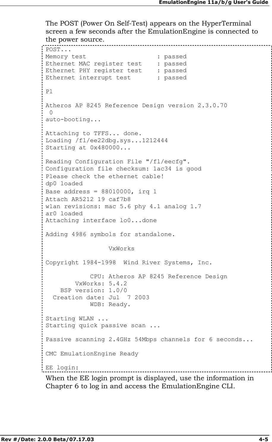
Ixia EE11ABG 802.11 a/b/g Emulation Engine User Manual EmulationEngine 11a b g User s Guide
Ixia 802.11 a/b/g Emulation Engine EmulationEngine 11a b g User s Guide
Ixia >
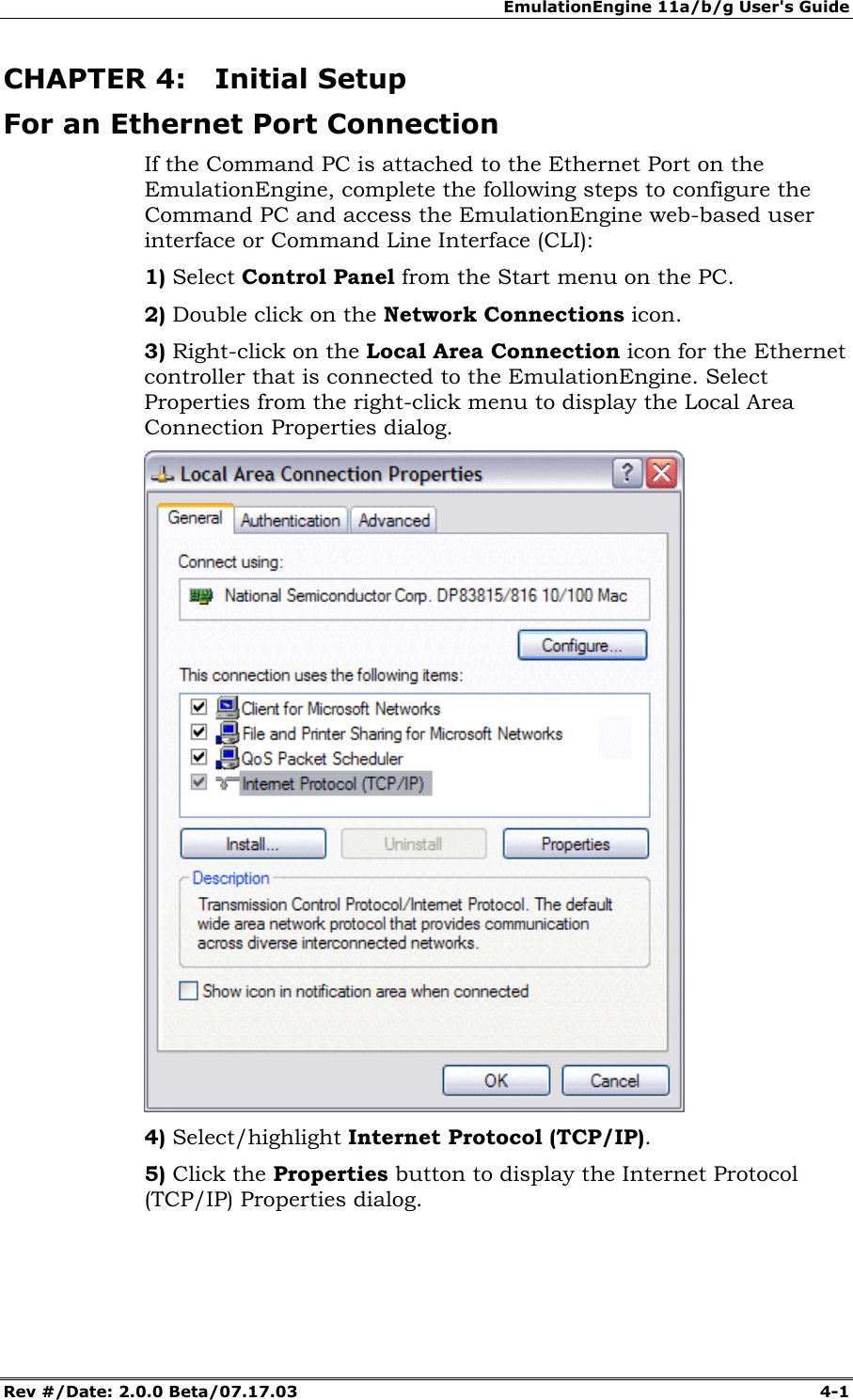
Contents
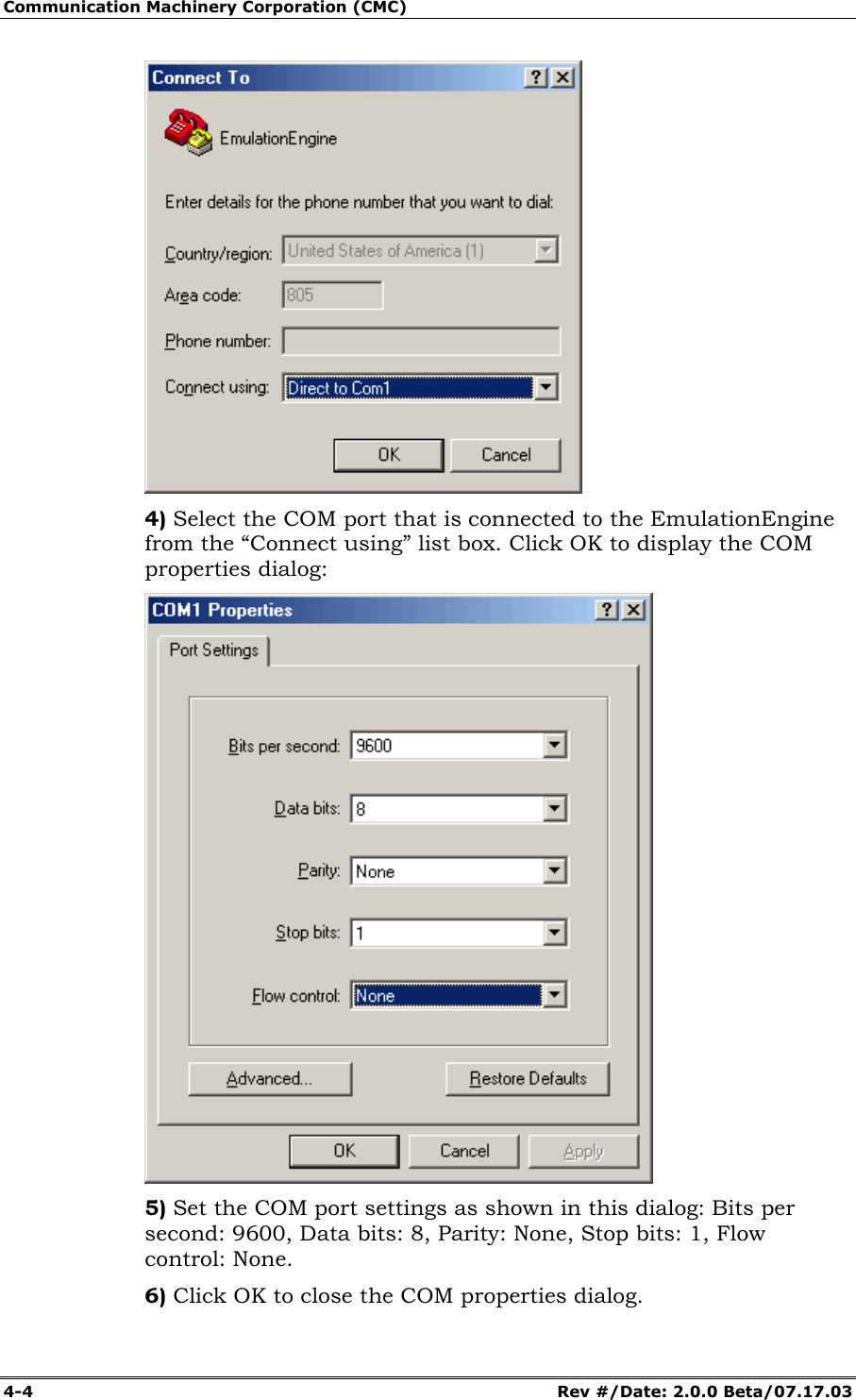
- 1. User Manual 1 of 3
- 2. User Manual 2 of 3
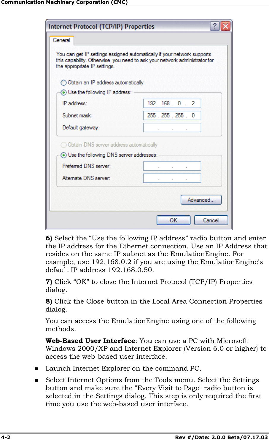
- 3. User Manual 3 of 3
User Manual 1 of 3

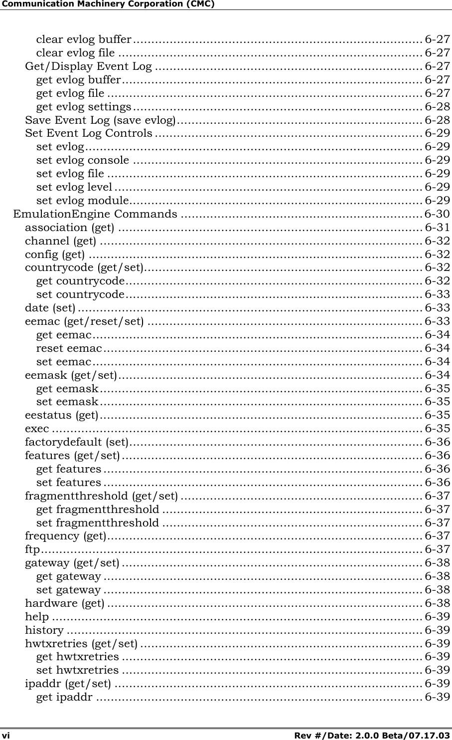

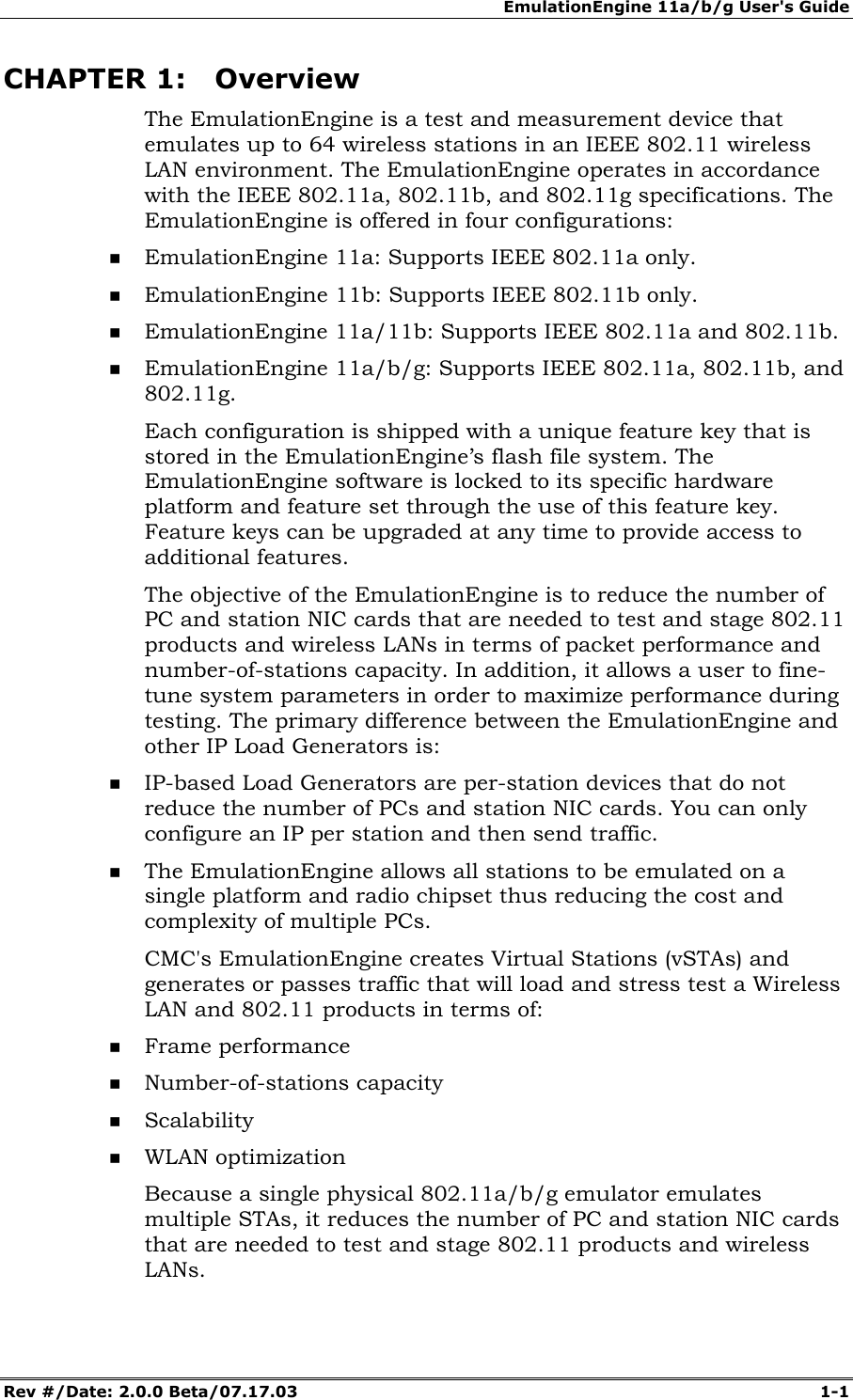


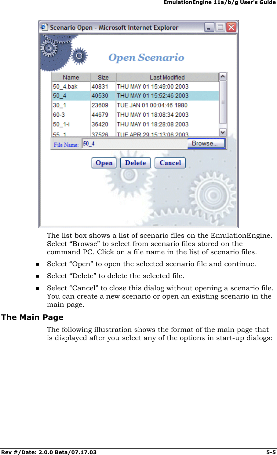
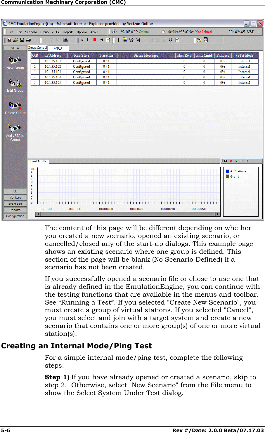
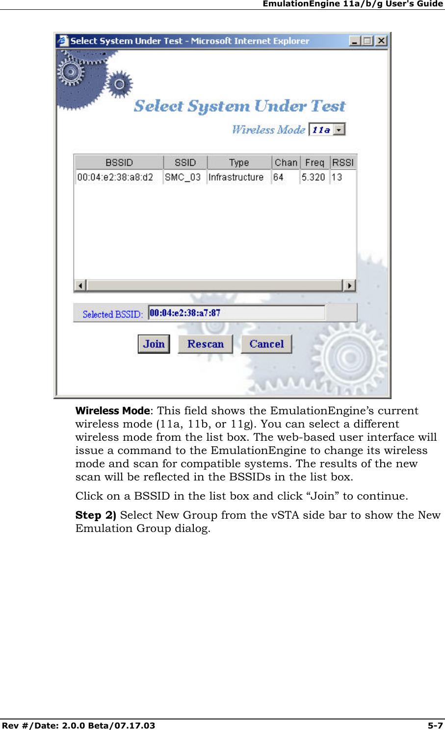
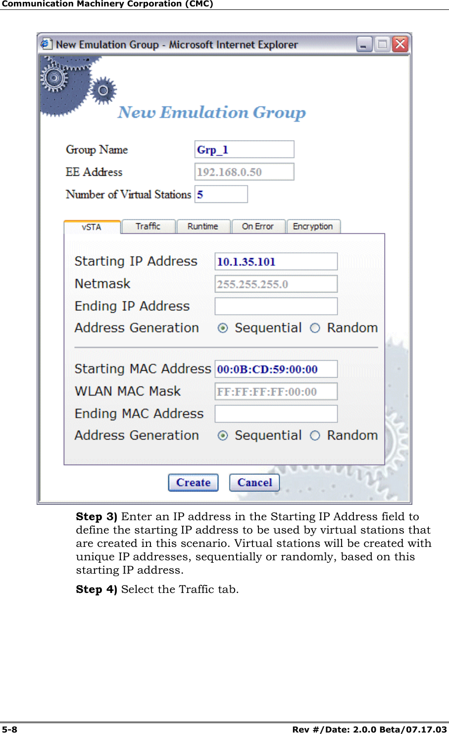

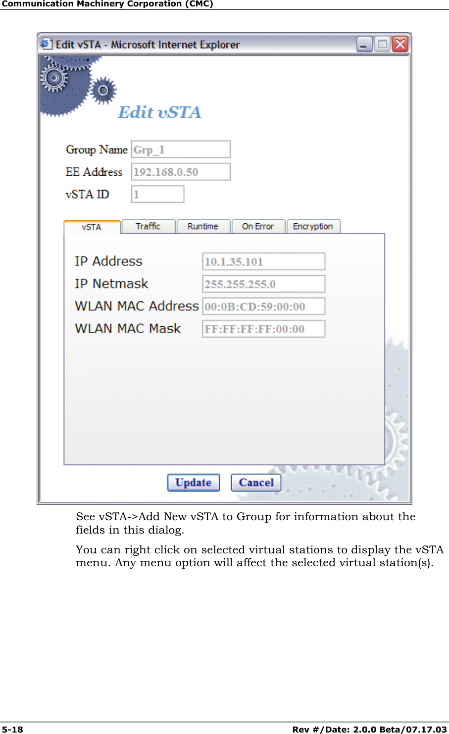
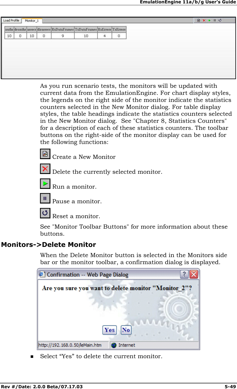
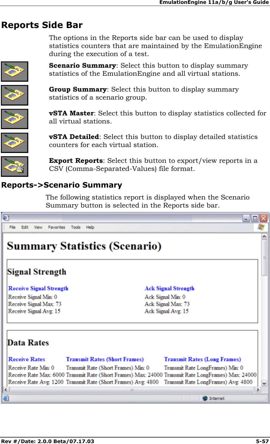
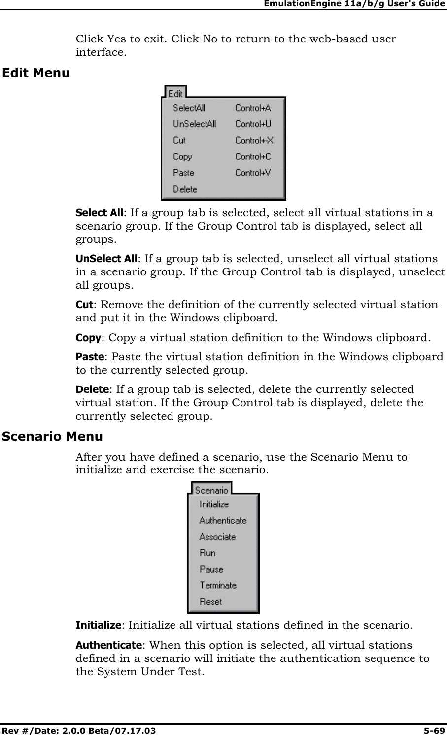
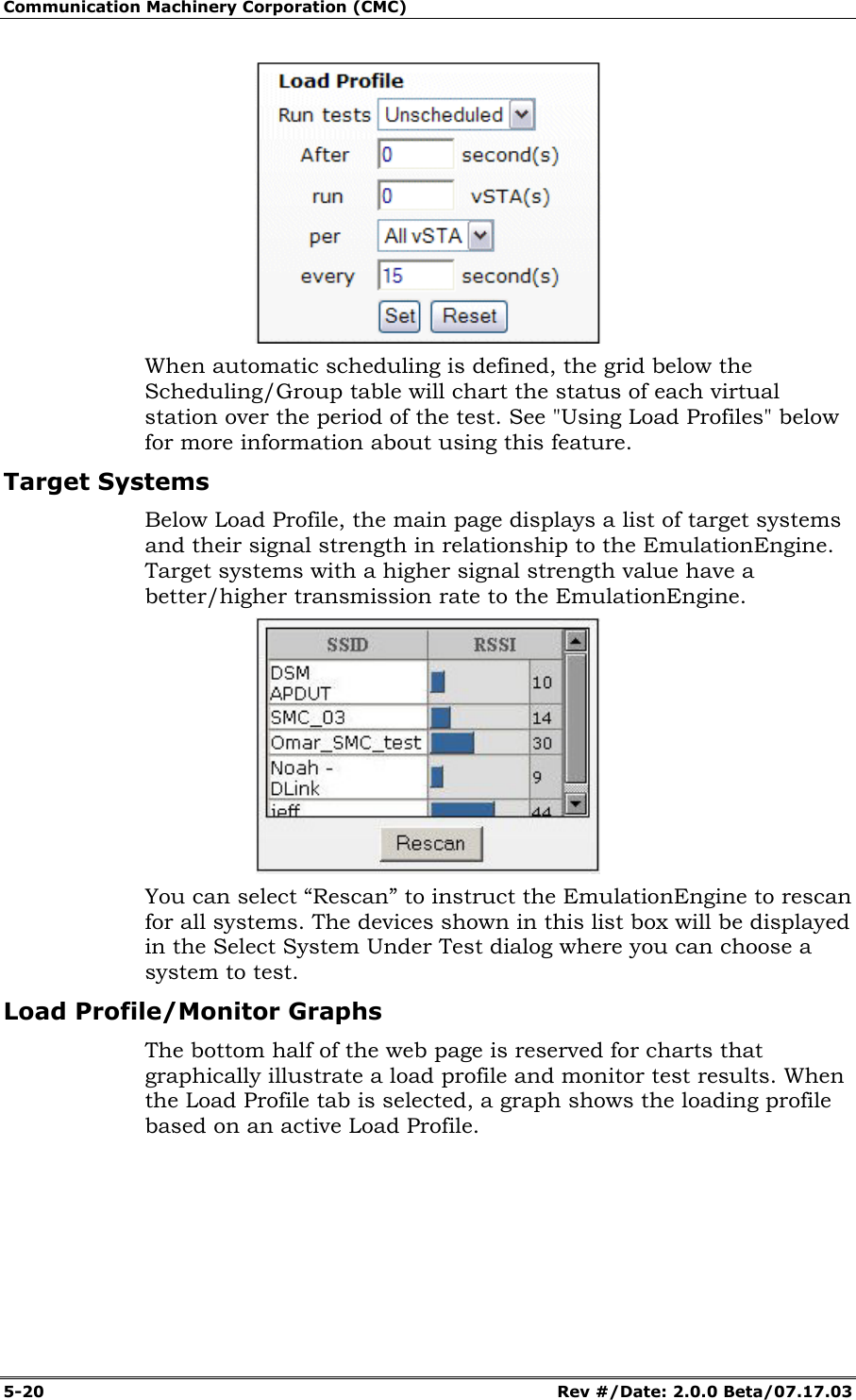
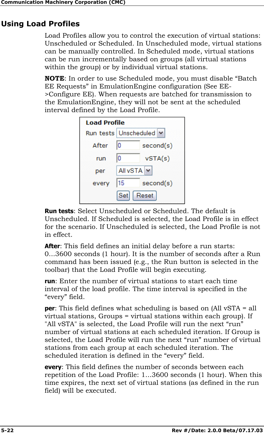
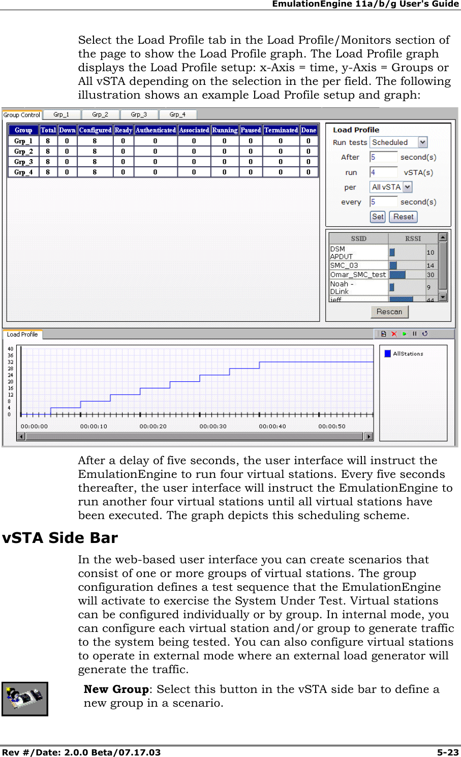
![EmulationEngine 11a/b/g User's Guide Rev #/Date: 2.0.0 Beta/07.17.03 5-19 Group Tab Columns: Within a group, you can double click on the table heading to configure the columns that are displayed. Select one or more items in the All Columns list box and click the [>>] button to move them to the Selected Columns list box. Click “Modify” to add the columns to the group table. Select “Reset” to return the columns to their default setting. Load Profile The Load Profile section of the page can be used to automatically execute scenarios at scheduled intervals.](https://usermanual.wiki/Ixia/EE11ABG.User-Manual-1-of-3/User-Guide-352251-Page-45.png)

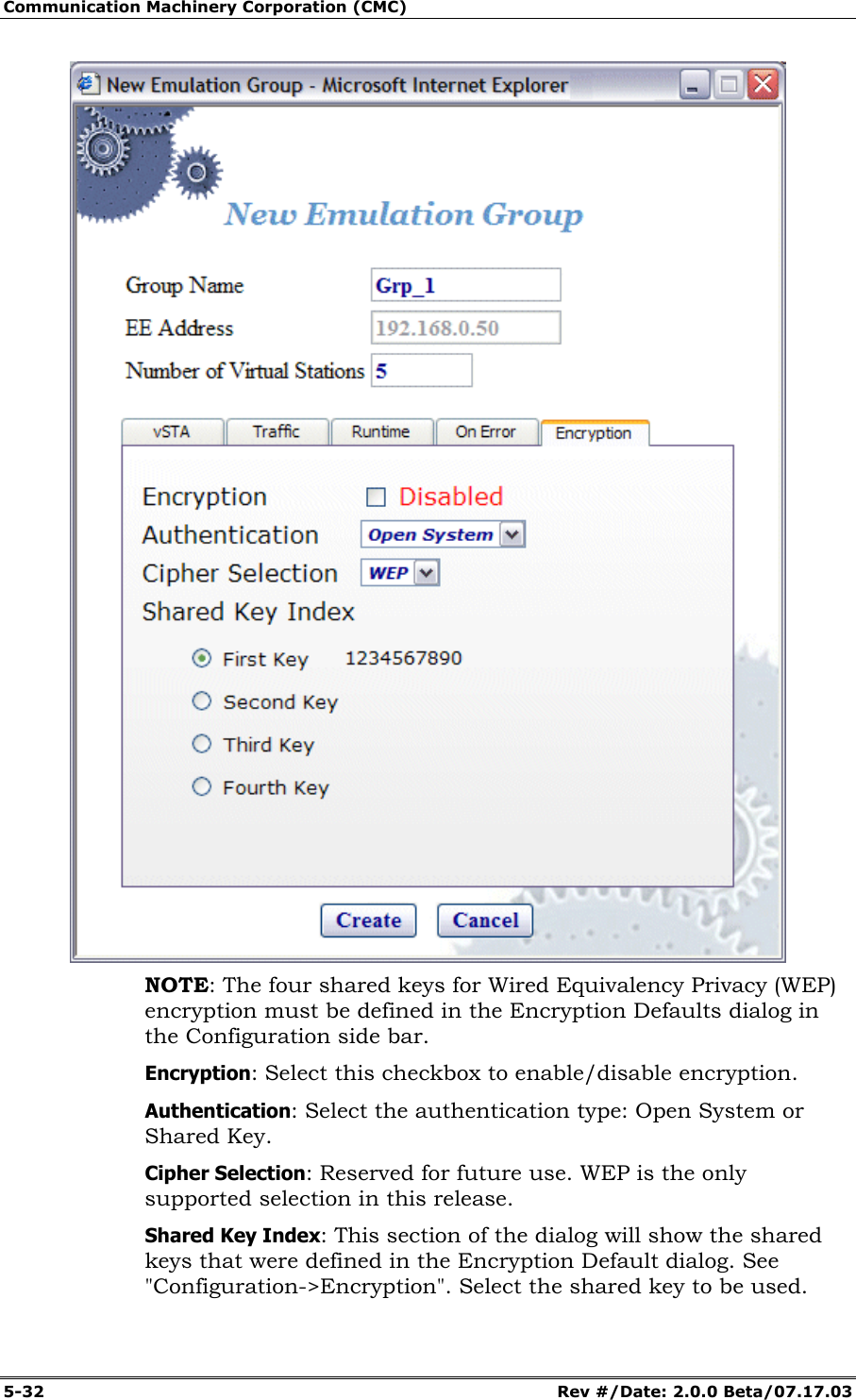
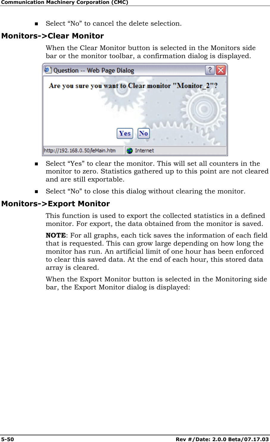
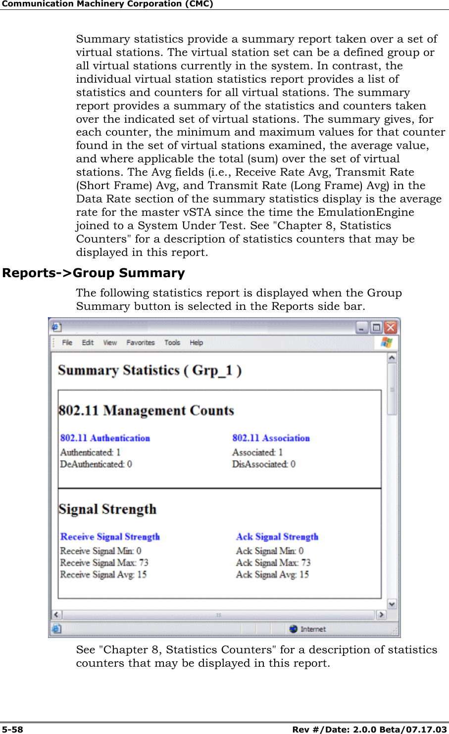
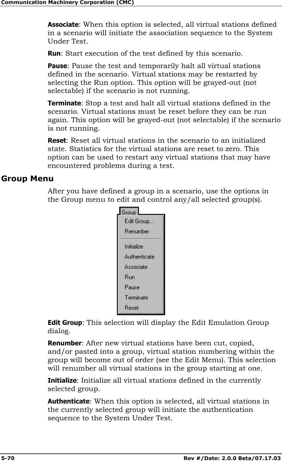
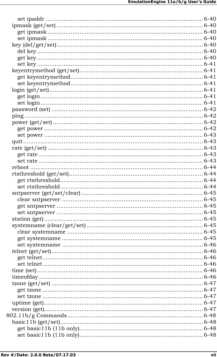
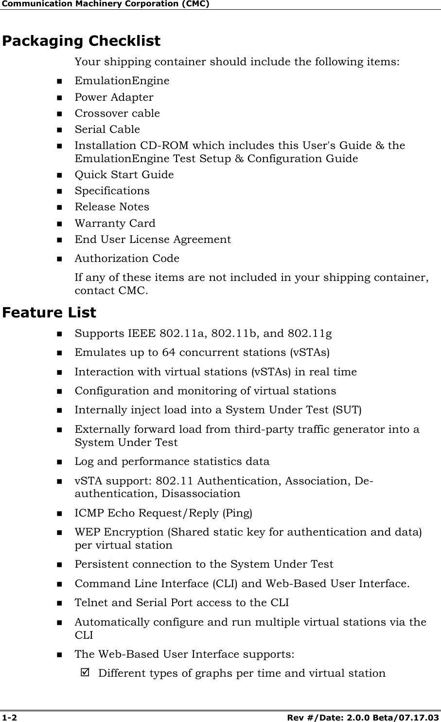
![Communication Machinery Corporation (CMC) 5-46 Rev #/Date: 2.0.0 Beta/07.17.03 Monitor Name: Enter a monitor name. It can be up to 12 characters (a...z, 0..9, and underscore (_)). EE Address: This field shows the EmulationEngine's IP address. Display Style: Select a display style from the list box. It can be one of the following: Line Graph, Bar Graph, or Table. Monitors->Selected Monitors: Select one of the monitors to be maintained. Use the [>>] button (or double-click the line item) to transfer the predefined monitor to the Selected Monitors column. See "Chapter 8, Statistics Counters" for a description of each of these statistics counters. Click “Create” to create and display the monitor. Click “Cancel” to close this dialog. Monitors->New Monitor->Summary Use the Summary section of the Define New Monitor dialog to select summary statistics counters.](https://usermanual.wiki/Ixia/EE11ABG.User-Manual-1-of-3/User-Guide-352251-Page-72.png)
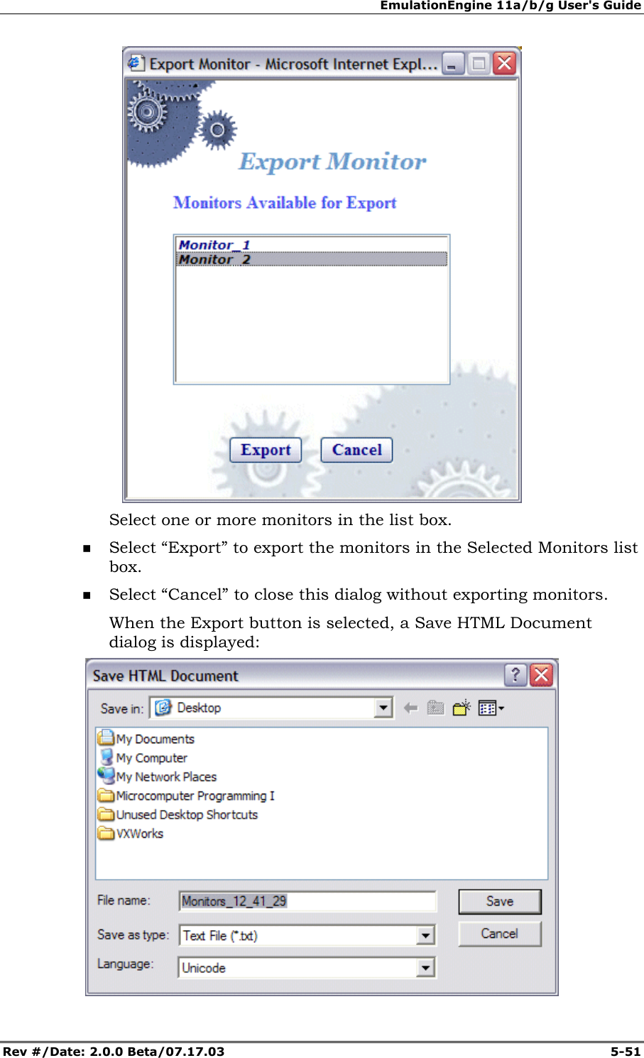
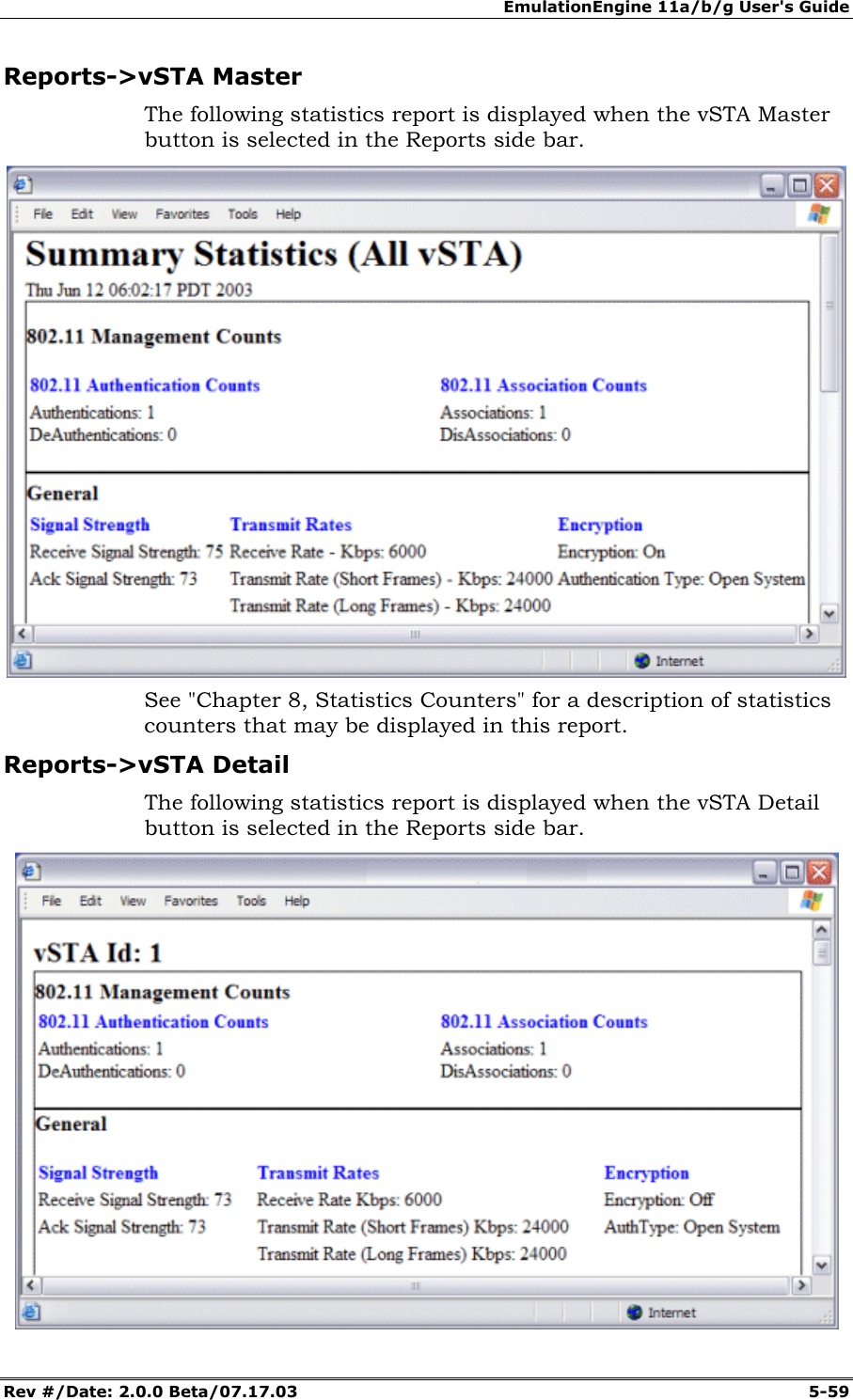
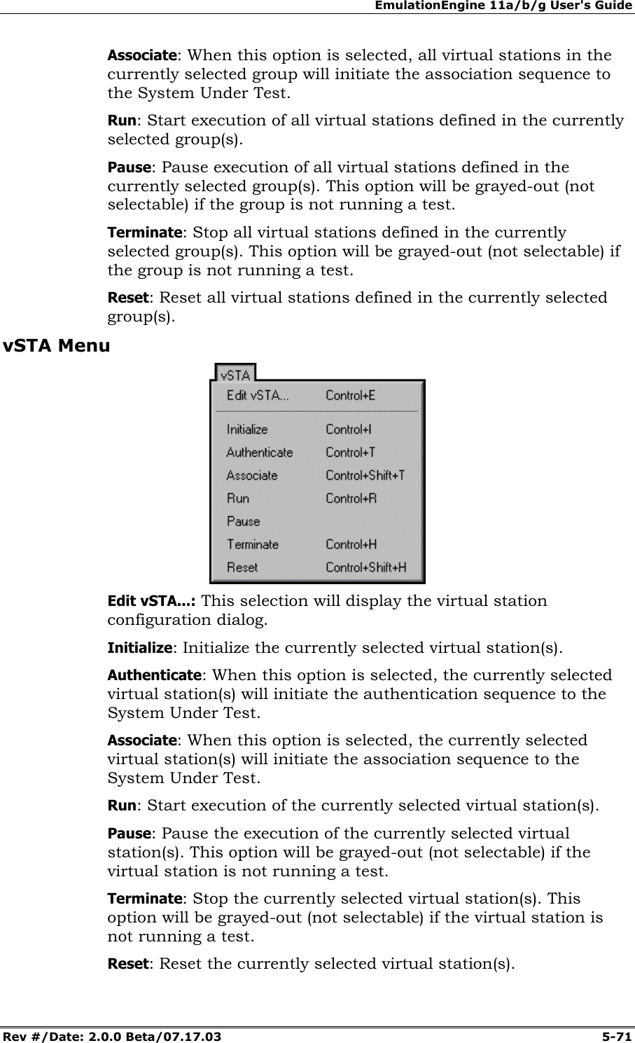
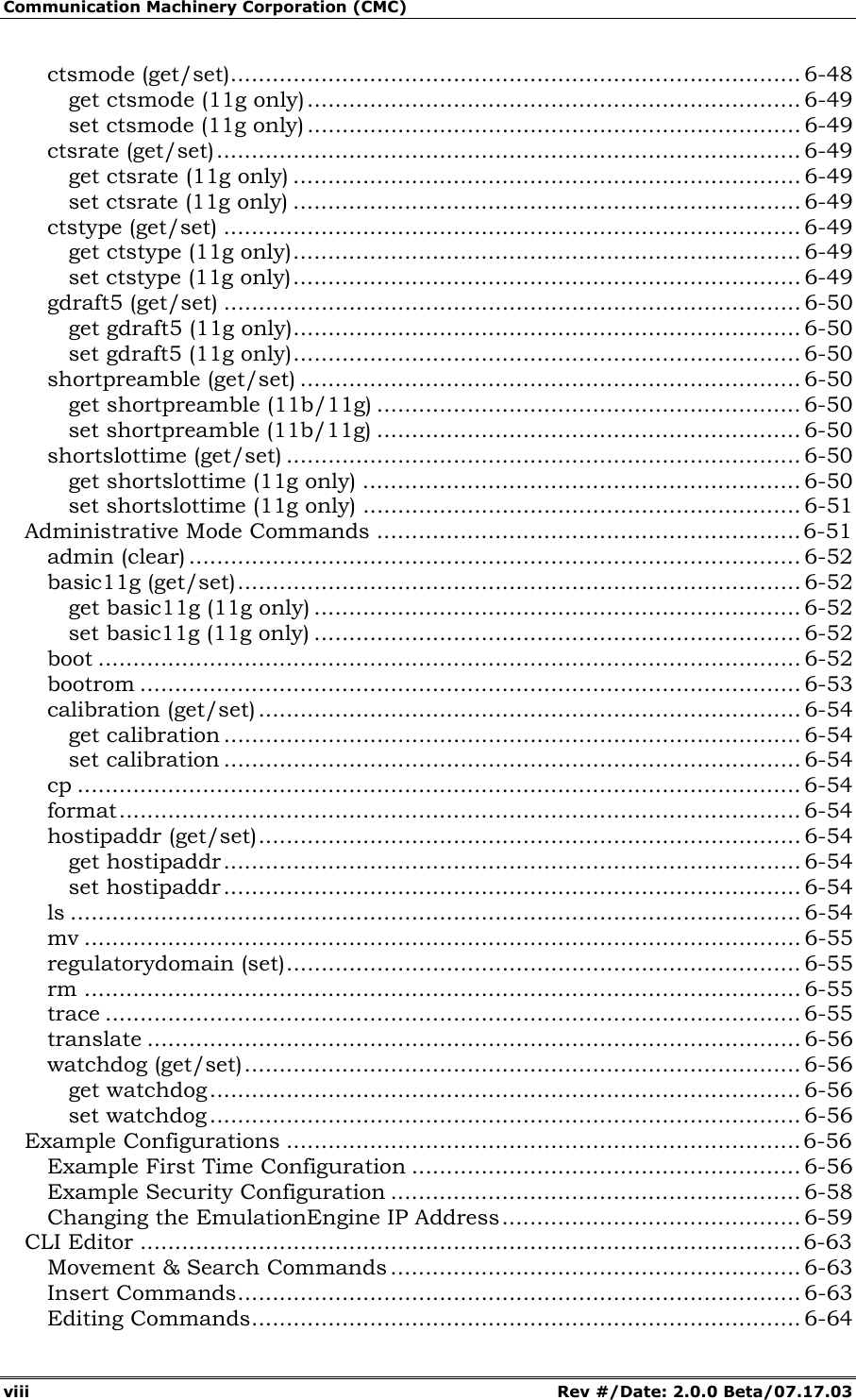
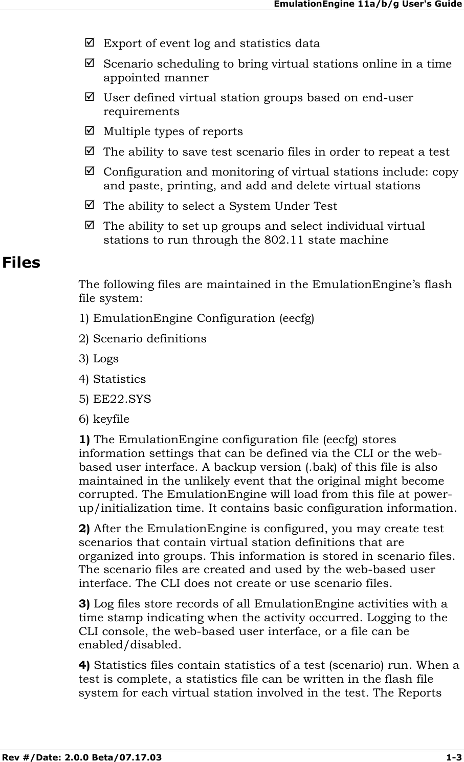
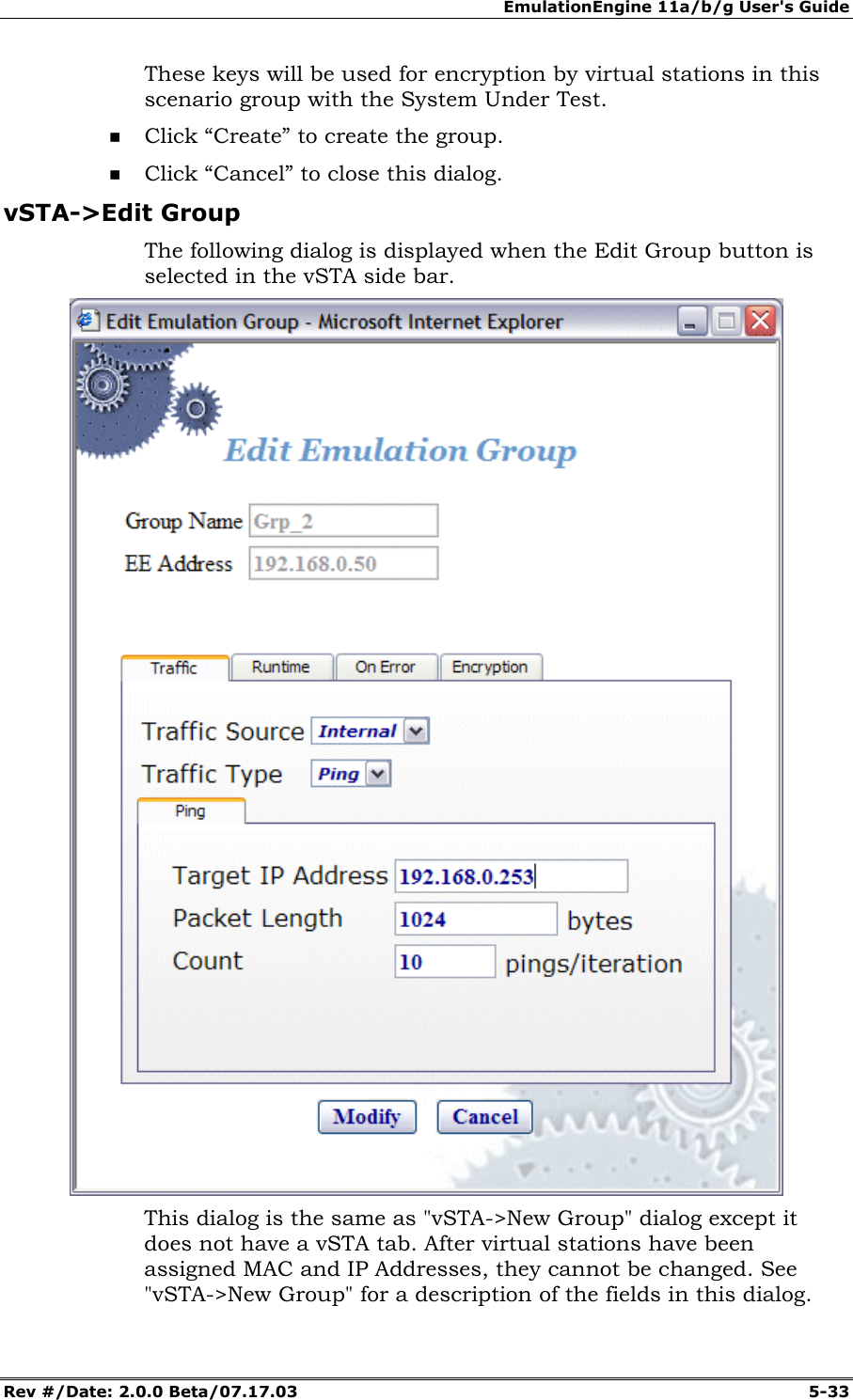
![EmulationEngine 11a/b/g User's Guide Rev #/Date: 2.0.0 Beta/07.17.03 5-47 Summary Counters->Selected Counters: Select one or more of the counters to be maintained in the test results file. Use the [>>] button to transfer the counters to the Selected Counters column. See "Chapter 8, Statistics Counters" for a description of each of these statistics counters. Click “Create” to create and display the monitor. Click “Cancel” to close this dialog. Monitors->New Monitor->vSTA Use the vSTA section of the Define New Monitor dialog to select the master (summary) virtual station statistics counters.](https://usermanual.wiki/Ixia/EE11ABG.User-Manual-1-of-3/User-Guide-352251-Page-73.png)
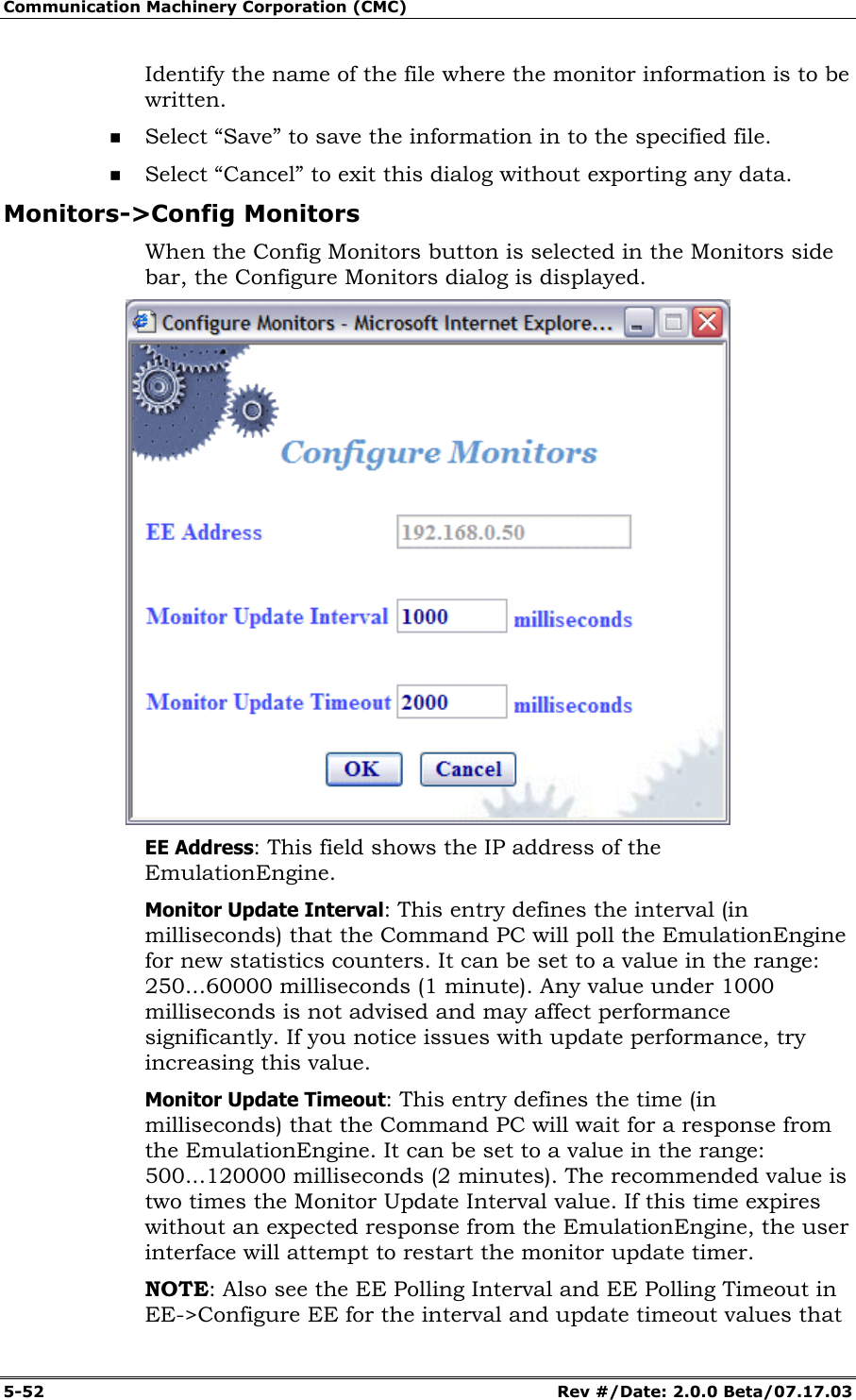
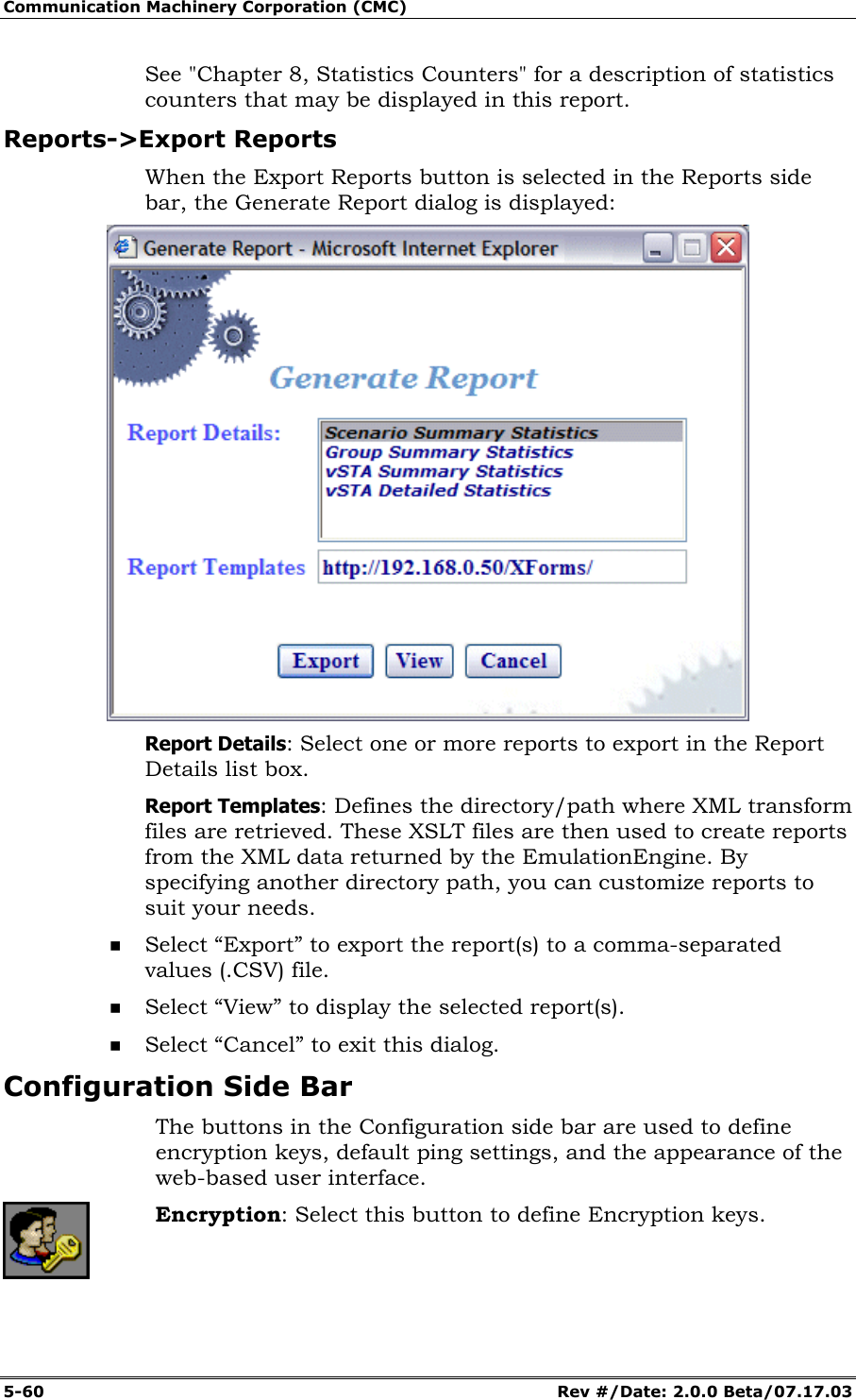
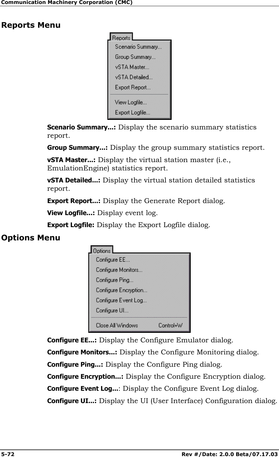
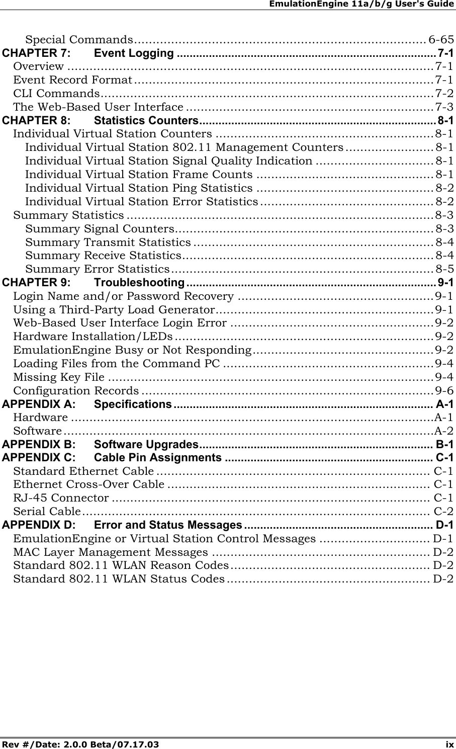
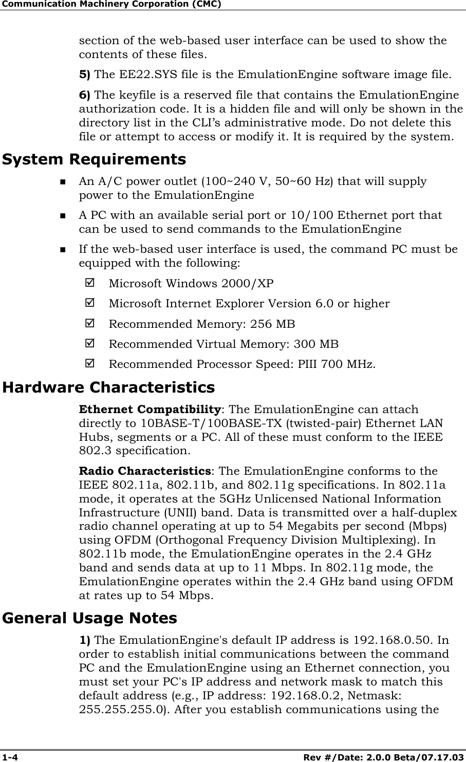
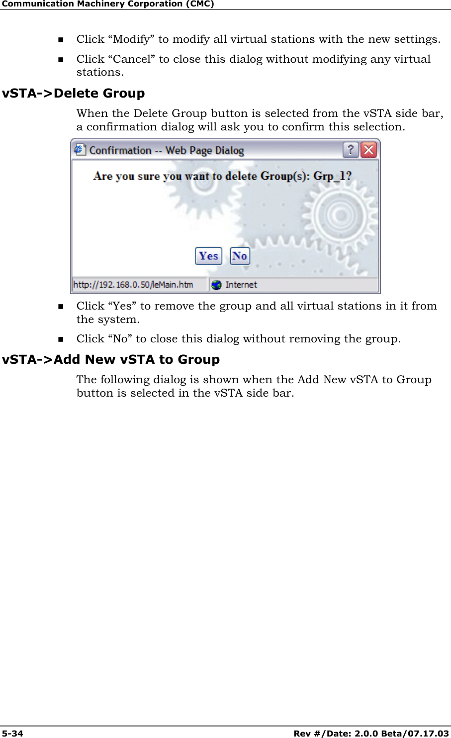
![Communication Machinery Corporation (CMC) 5-48 Rev #/Date: 2.0.0 Beta/07.17.03 vSTA (s): Select a virtual station from the list box. The Master Station is a summary that shows virtual station statistics across all virtual stations. vSTA Counters->Selected Counters: Select one or more of the counters to be maintained in the test results file. Use the [>>] button to transfer the counters to the Selected Counters column. See "Chapter 8, Statistics Counters" for a description of each of these statistics counters. Click “Create” to create and display the monitor. Click “Cancel” to close this dialog. When you select one or more counters and choose the Create button, the bottom half of the screen will show the current results in the selected display style. Example:](https://usermanual.wiki/Ixia/EE11ABG.User-Manual-1-of-3/User-Guide-352251-Page-74.png)