Ixia GC617644 802.11a/b/g Multi AP Emulator (Client Device) User Manual IxWLANUserGuide
Ixia 802.11a/b/g Multi AP Emulator (Client Device) IxWLANUserGuide
Ixia >
Contents
User Manual 1

IxWLAN™ User Guide
Release 6.20
Part No. 913-0073-03 Rev A
May 2007

ii IxWLAN User Guide, Release 6.20
Copyright © 2007 Ixia. All rights reserved.
This publication may not be copied, in whole or in part, without Ixia’s consent.
RESTRICTED RIGHTS LEGEND: Use, duplication, or disclosure by the U.S. Government is subject to the restrictions set forth in
subparagraph (c)(1)(ii) of the Rights in Technical Data and Computer Software clause at DFARS 252.227-7013 and FAR 52.227-
19.
Ixia, the Ixia logo, and all Ixia brand names and product names in this document are either trademarks or registered trademarks of
Ixia in the United States and/or other countries. All other trademarks belong to their respective owners.
The information herein is furnished for informational use only, is subject to change by Ixia without notice, and should not be con-
strued as a commitment by Ixia. Ixia assumes no responsibility or liability for any errors or inaccuracies contained in this publica-
tion.
Part No. 913-0073-03 Rev A
May 14, 2007
Corporate
Headquarters Ixia Worldwide Headquarters
26601 W. Agoura Rd.
Calabasas, CA 91302
USA
+1 877 FOR IXIA (877 367 4942)
+1 818 871 1800 (International)
(FAX) +1 818 871 1805
sales@ixiacom.com
Web site: www.ixiacom.com
General: info@ixiacom.com
Investor Relations: ir@ixiacom.com
Training: training@ixiacom.com
Support: support@ixiacom.com
+1 877 367 4942
EMEA Ixia Europe Limited
Globeside Business Park
Building One, Unit A
Marlow, SL7 1GJ
United Kingdom
+44 1869 356370
(FAX) +44 1869 356371
ixiaeurope@ixiacom.com
Support: eurosupport@ixiacom.com
+44 1869 356370 (Option 5)
Asia Pacific Asia Pacific Representative Office
New Shanghai International Tower, Suite 26E
360 Pudong Nan Rd
Shanghai 200120
China
+86 21 50543439
ixiachina@ixiacom.com
Support: support@ixiacom.com
+1 818 871 1800 (Option 1)
Japan Ixia KK
Aioi Sampo Shinjuku Building, 16th Floor
3-25-3 Yoyogi Shibuya-Ku
Tokyo 151-0053
Japan
+81 3 5365 4690
(FAX) +81 3 3299 6263
ixiajapan@ixiacom.com
Support: support@ixiacom.com
+1 818 871 1800 (Option 1)
India Ixia India
No. 508, 6th Main 6th Cross
ST Bed, Koramangala 4th Block
Bangalore 560 034
India
+91 80 25633570
(FAX) +91 80 25633487
ixiaindia@ixiacom.com
Support: support-india@ixiacom.com
+91 80 32918500

IxWLAN User Guide, Release 6.20 iii
Table of Contents
Chapter 1 Introduction
Introduction to IxWLAN . . . . . . . . . . . . . . . . . . . . . . . . . . . . . 1-1
Packaging Checklist . . . . . . . . . . . . . . . . . . . . . . . . . . . . . . . 1-3
Features . . . . . . . . . . . . . . . . . . . . . . . . . . . . . . . . . . . . . . . . 1-4
WPA/RSN . . . . . . . . . . . . . . . . . . . . . . . . . . . . . . . . . . . . . . . 1-6
Files. . . . . . . . . . . . . . . . . . . . . . . . . . . . . . . . . . . . . . . . . . . . 1-8
System Needs. . . . . . . . . . . . . . . . . . . . . . . . . . . . . . . . . . . 1-10
Hardware Characteristics . . . . . . . . . . . . . . . . . . . . . . . . . . 1-10
General Usage Notes . . . . . . . . . . . . . . . . . . . . . . . . . . . . . 1-12
Feature Key Dependent Parameters. . . . . . . . . . . . . . . . . . 1-13
Chapter 2 Installation
Attaching the Antennas . . . . . . . . . . . . . . . . . . . . . . . . . . . . . 2-1

Table of Contents
iv IxWLAN User Guide, Release 6.20
Connecting Directly to a Command PC . . . . . . . . . . . . . . . . 2-2
Connecting Through an Ethernet Hub or Switch . . . . . . . . . 2-3
Connecting to the Serial Port. . . . . . . . . . . . . . . . . . . . . . . . 2-3
Chapter 3 First Setup
Using the Ethernet Ports . . . . . . . . . . . . . . . . . . . . . . . . . . . 3-1
Using the Serial Port . . . . . . . . . . . . . . . . . . . . . . . . . . . . . . 3-5
Chapter 4 The Web-Based User Interface
Startup and Login. . . . . . . . . . . . . . . . . . . . . . . . . . . . . . . . . 4-1
Choosing and Creating a Scenario . . . . . . . . . . . . . . . . . . . 4-3
Using the Main Page . . . . . . . . . . . . . . . . . . . . . . . . . . . . . 4-14
vSTA Side Bar . . . . . . . . . . . . . . . . . . . . . . . . . . . . . . . . . . 4-25
IxWLAN Side Bar. . . . . . . . . . . . . . . . . . . . . . . . . . . . . . . . 4-40
Monitors Side Bar . . . . . . . . . . . . . . . . . . . . . . . . . . . . . . . 4-55
Event Log Side Bar . . . . . . . . . . . . . . . . . . . . . . . . . . . . . . 4-63
Reports Side Bar . . . . . . . . . . . . . . . . . . . . . . . . . . . . . . . . 4-66
Configuration Side Bar. . . . . . . . . . . . . . . . . . . . . . . . . . . . 4-71
Menus and Tool Bars . . . . . . . . . . . . . . . . . . . . . . . . . . . . . 4-78

IxWLAN User Guide, Release 6.20 v
Table of Contents
Chapter 5 The Command Line Interface (CLI)
CLI Usage Notes. . . . . . . . . . . . . . . . . . . . . . . . . . . . . . . . . . 5-3
User Login. . . . . . . . . . . . . . . . . . . . . . . . . . . . . . . . . . . . . . . 5-3
User Logoff . . . . . . . . . . . . . . . . . . . . . . . . . . . . . . . . . . . . . . 5-4
CLI Commands . . . . . . . . . . . . . . . . . . . . . . . . . . . . . . . . . . . 5-4
System Under Test Commands. . . . . . . . . . . . . . . . . . . . . . . 5-7
Virtual Station Setup and Control Commands. . . . . . . . . . . 5-14
Statistics File Commands . . . . . . . . . . . . . . . . . . . . . . . . . . 5-52
Event Log Commands. . . . . . . . . . . . . . . . . . . . . . . . . . . . . 5-54
IxWLAN Commands . . . . . . . . . . . . . . . . . . . . . . . . . . . . . . 5-59
802.11b/g Commands . . . . . . . . . . . . . . . . . . . . . . . . . . . . . 5-87
Administrative Mode Commands . . . . . . . . . . . . . . . . . . . . 5-91
Example Configurations . . . . . . . . . . . . . . . . . . . . . . . . . . . 5-98
CLI Editor . . . . . . . . . . . . . . . . . . . . . . . . . . . . . . . . . . . . . 5-115
Chapter 6 The Programming Interface (Perl)
Chapter 7 Statistics Counters
Individual Virtual Station Counters . . . . . . . . . . . . . . . . . . . . 7-1
Summary Statistics . . . . . . . . . . . . . . . . . . . . . . . . . . . . . . . . 7-7

Table of Contents
vi IxWLAN User Guide, Release 6.20
wport Statistics . . . . . . . . . . . . . . . . . . . . . . . . . . . . . . . . . . 7-16
Chapter 8 Troubleshooting
Login Name and/or Password Recovery . . . . . . . . . . . . . . . 8-1
Using a Third-Party Load Generator . . . . . . . . . . . . . . . . . . 8-2
Chassis Installation and LEDs . . . . . . . . . . . . . . . . . . . . . . . 8-2
Web-Based User Interface Problems . . . . . . . . . . . . . . . . . 8-3
Missing Key File. . . . . . . . . . . . . . . . . . . . . . . . . . . . . . . . . . 8-7
Recovering a Corrupted Firmware File . . . . . . . . . . . . . . . . 8-9
Configuration Records . . . . . . . . . . . . . . . . . . . . . . . . . . . . 8-14
Appendix A Specifications
Hardware . . . . . . . . . . . . . . . . . . . . . . . . . . . . . . . . . . . . . . . A-1
Software. . . . . . . . . . . . . . . . . . . . . . . . . . . . . . . . . . . . . . . . A-2
Performance . . . . . . . . . . . . . . . . . . . . . . . . . . . . . . . . . . . . A-4
Appendix B Event Logging
Overview . . . . . . . . . . . . . . . . . . . . . . . . . . . . . . . . . . . . . . . B-1
Event Record Format. . . . . . . . . . . . . . . . . . . . . . . . . . . . . . B-2
CLI Commands . . . . . . . . . . . . . . . . . . . . . . . . . . . . . . . . . . B-3
The Web-Based User Interface . . . . . . . . . . . . . . . . . . . . . . B-4

IxWLAN User Guide, Release 6.20 vii
Table of Contents
Appendix C Software Updates
Using the Web-Based User Interface . . . . . . . . . . . . . . . . . .C-1
Using the CLI. . . . . . . . . . . . . . . . . . . . . . . . . . . . . . . . . . . . .C-3
Appendix D Cable Pin Assignments
Standard Ethernet Cable. . . . . . . . . . . . . . . . . . . . . . . . . . . .D-1
Ethernet Crossover Cable. . . . . . . . . . . . . . . . . . . . . . . . . . .D-2
RJ-45 Connector . . . . . . . . . . . . . . . . . . . . . . . . . . . . . . . . . .D-2
Serial Cable. . . . . . . . . . . . . . . . . . . . . . . . . . . . . . . . . . . . . .D-3
Appendix E Error and Status Messages
IxWLAN or Virtual Station Control Messages . . . . . . . . . . . .E-1
WLAN Driver Error Messages. . . . . . . . . . . . . . . . . . . . . . . .E-5
MAC Layer Management Messages. . . . . . . . . . . . . . . . . . .E-6
Standard 802.11 WLAN Reason Codes . . . . . . . . . . . . . . . .E-7
Standard 802.11 WLAN Status Codes . . . . . . . . . . . . . . . . .E-8
Appendix F Additional Copyright and Trademark Notices
Appendix G Regulatory Information
Radio Frequency Interference Needs . . . . . . . . . . . . . . . . . G-1
FCC Declarations of Conformity and Warning . . . . . . . . . . G-1

Table of Contents
viii IxWLAN User Guide, Release 6.20
RF Exposure Needs. . . . . . . . . . . . . . . . . . . . . . . . . . . . . . . G-2
EU Declarations of Conformity (Europe) . . . . . . . . . . . . . . . G-2
Glossary
Index

IxWLAN User Guide, Release 6.20 1-1
1Chapter 1: Introduction
This chapter covers the following topics:
•Introduction to IxWLAN on page 1-1.
•Packaging Checklist on page 1-3.
•Features on page 1-4.
•WPA/RSN on page 1-6.
•Files on page 1-8.
•System Needs on page 1-10.
•Hardware Characteristics on page 1-10.
•General Usage Notes on page 1-12.
•Feature Key Dependent Parameters on page 1-13.
Introduction to IxWLAN
IxWLAN is a test and measurement device that emulates up to 128 wireless sta-
tions in an IEEE 802.11 wireless LAN environment. It operates in accordance
with the IEEE 802.11a, IEEE 802.11b, and IEEE 802.11g specifications. IxW-
LAN is offered in the following configurations:
•IxWLAN SED 11a/b/g – Supports IEEE 802.11a, 802.11b, and 802.11g,
depending on regulatory certifications.
•IxWLAN SED-MR+ 11a/b/g – Supports IEEE 802.11a, 802.11b, and
802.11g.
Both configurations include the IEEE 802.11i and WiFi Protected Access (WPA)
security features.
IxWLAN can be used to reduce the number of PCs and station NIC cards that are
needed to test and stage 802.11 products and wireless LANs in terms of packet

Introduction
Introduction to IxWLAN
1-2 IxWLAN User Guide, Release 6.20
1
performance and number-of-stations capacity. It allows a user to fine-tune sys-
tem parameters to maximize performance during testing.
The differences between IxWLAN and other IP load generators can be summa-
rized as follows:
•IP-based Load Generators are per-station devices that do not reduce the num-
ber of PCs and station NIC cards. You can configure only one IP per station
and then send traffic.
•IxWLAN allows all stations to be emulated on a single platform and radio
chipset, thus reducing the cost and complexity of multiple PCs.
IxWLAN creates Virtual Stations (vSTAs) and generates or passes traffic that
loads and stress tests Wireless LAN and 802.11 products in terms of:
•Frame performance
•Number-of-stations capacity
•Scalability
•WLAN optimization
Because a single physical 802.11a/b/g emulator emulates multiple vSTAs, it
reduces the number of PC and station NIC cards that are needed to test and stage
802.11 products and wireless LANs.
As of 6.20 version, IxWLAN is supported by two chassis, the IxWLAN SED and
the IxWLAN SED-MR+.
IxWLAN SED Figure 1-1 shows the IxWLAN SED chassis.
Figure 1-1. IxWLAN SED Chassis
External Traffic
Generator port
Serial port
Management port
Activity LED Status LED
Power LED

IxWLAN User Guide, Release 6.20 1-3
Introduction
Packaging Checklist
IxWLAN SED-MR+ Figure 1-2 shows the IxWLAN SED-MR+ chassis.
Figure 1-2. IxWLAN SED-MR+ Chassis
Packaging Checklist
Your shipping container must include the following items:
•Chassis (IxWLAN SED or SED-MR+)
•Power cord for the IxWLAN SED or SED-MR+ chassis
•Crossover cable
•Serial cable
•Detachable multiband antennas (2 for the IxWLAN SED and 3 for the SED-
MR+ chassis)
•Data sheet
•Specifications
•Release Notes
•Warranty card
•End User License Agreement
•Installation CD-ROM, which includes this User Guide and the IxWLAN
SDK.
If any of these items is not included in your shipping container, contact Ixia Cus-
tomer Support.

Introduction
Features
1-4 IxWLAN User Guide, Release 6.20
1
Features
•Supports IEEE 802.11a, 802.11b, 802.11g
•Supports 802.11h Dynamic Frequency Selection (DFS) and Transmit Power
Control (TPC)
•The IxWLAN SED chassis emulates up to 64 concurrent virtual stations,
while the IxWLAN SED-MR+ chassis supports up to 128 virtual stations.
•Interaction with virtual stations in real time
•Configuration and monitoring of virtual stations
•Internally injects load into a System Under Test (SUT)
•Externally forwards load from a third-party traffic generator to a System
Under Test
•For the external mode, frames can be captured based on the source 802.3
MAC address (Layer 2) or the source IP address (Layer 3).
•Event Log and performance statistics data
•vSTA support: 802.11 Authentication, Association, De-authentication, Disas-
sociation, Reassociation.
•The system supports Open-System, Shared-Key WEP, WPA, and 802.11i
(RSN) security, including 802.11i Pre-Authentication.
•The system supports 802.11i PMKSA caching and re-use.
•The system supports fast RADIUS reconnection in vSTAs configured for
WPA and RSN authentication types.
•The system allows for each vSTA to be configured with a unique SSID, to
transmit 802.11 Probe Request frames and to receive directed 802.11 Probe
Response frames. This allows users to configure vSTAs to exercise an AP’s
WLAN-to-VLAN code using a single IxWLAN chassis.
•Virtual stations may independently roam between APs comprising an ESS
wireless network.
•ICMP Echo Request/Reply (Ping)
•Security per vSTA (Table 1-1)
Table 1-1. Authentication
Authentication Cipher Security Configuration Additional Security
Configuration
Open-System WEP Up to 4 Shared Static Keys for
authentication and data
Shared-Key WEP Up to 4 Shared Static Keys for
authentication and data

IxWLAN User Guide, Release 6.20 1-5
Introduction
Features
•Persistent connection to the System Under Test
•DHCP Client: vSTAs can have IP addresses dynamically assigned from a
DHCP server on the network rather than a fixed, configured IP address.
•Command Line Interface and Web-Based User Interface
•Telnet and Serial Port access to the CLI
•Automatically configure and run multiple virtual stations using the CLI
•The Web-Based User Interface supports the following:
•Real-time graphs of test results for each virtual station, and for the system
as a whole
•Export of event log and statistics data
•Scenario scheduling to bring vSTAs online in a time-appointed manner
•User-defined virtual station groups based on end user needs
•Multiple types of reports
•The ability to save test scenario files in order to repeat a test
•Configuration and monitoring of virtual stations include: copy, paste, print,
add, and delete virtual stations
•The ability to select a System Under Test
•The ability to set up groups and select individual virtual stations to run
through the 802.11 state machine
WPA TKIP or AES-CCM EAP Algorithm: TLS, TTLS, or
PEAP
User ID/Client Certificate File. For
TTLS/PEAP, Inner Algorithm (MS-
CHAPv2, EAP-MS-CHAPv2),
Outer ID, and Password.
WPA-PSK TKIP or AES-CCM Pre-Shared Key or Passphrase
RSN TKIP or AES-CCM EAP Algorithm: TLS, TTLS, or
PEAP
User ID/Client Certificate File. For
TTLS/PEAP, Inner Algorithm (MS-
CHAPv2, EAP-MS-CHAPv2),
Outer ID, and Password.
RSN-PSK TKIP or AES-CCM Pre-Shared Key or Passphrase
Table 1-1. Authentication (Continued)
Authentication Cipher Security Configuration Additional Security
Configuration

Introduction
WPA/RSN
1-6 IxWLAN User Guide, Release 6.20
1
WPA/RSN
This section covers the following topics:
•Introduction to WPA/RSN on page 1-6.
•EAP Algorithms on page 1-7.
•Certificate Files on page 1-7.
•Key Hierarchy and Configuration on page 1-7.
•Protocol Conformance Testing on page 1-8.
Introduction to
WPA/RSN
Individual virtual stations can be configured with WPA or RSN authentication. A
vSTA can be configured to use either PSK or full 802.1X/EAP authentication.
RSN does the strong security of IEEE 802.11i.
The strength of WPA/RSN comes from an integrated sequence of operations that
encompass 802.1X/EAP authentication and sophisticated key management and
encryption techniques.
The IxWLAN implementation of WPA/RSN provides the following major opera-
tions:
•Network security capability determination – This occurs at the 802.11 level
and it is communicated through the WPA/RSN information elements in Bea-
con, Probe Response, and (Re) Association Requests. The information in
these elements includes the authentication method (802.1X or PSK) and the
preferred cipher suite (WEP, TKIP, or AES-CCM).
•Authentication – For full implementation of WPA/RSN, EAP over 802.1X is
used for authentication. Mutual authentication is gained by choosing an EAP
type supporting this feature. 802.1X port access control prevents full access
to the network until authentication completes. In the case of WPA-PSK or
RSN-PSK, mutual authentication between peers (that is, a virtual station and
the System Under Test) is achieved through the 4-Way AKMP handshake
during which possession and liveness of the correct PSK is confirmed.
•Pre-Authentication – IxWLAN also supports pre-authentication, defined in
the 802.11i specification as a means of speeding up the roaming process by
authenticating with the server before the roam. The pre-authentication is
independent of the roam and may be performed with multiple APs.
•PMKSA Catching – IxWLAN supports PMKSA catching, defined in the
802.11i specification. PMKSA is the context resulting from a successful
IEEE 802.1X authentication exchange between a given vSTA and the
Authentication Server.
•Key management – The WPA and RSN feature gives a robust key generation/
management system that integrates the authentication and data privacy func-
tions. The keys are generated after successful authentication and through a
subsequent 4-way handshake between the station and System Under Test.

IxWLAN User Guide, Release 6.20 1-7
Introduction
WPA/RSN
802.1X EAPOL-Key packets are used by WPA and RSN to negotiate and derive
pairwise keys used to protect unicast traffic. Group key handshake is used to
deliver the group key to each virtual station for protecting multicast and broad-
cast class 3 data frames.
•Data Privacy (Encryption) – TKIP or AES-CCM (that is, CCMP) is used to
replace WEP with more sophisticated cryptographic and security techniques.
•Data integrity – TKIP adds a MIC at the end of each plain-text message
(MSDU) to ensure that the messages are not being spoofed or replayed. With
AES-CCM, the MIC is added to each transmitted MPDU.
EAP Algorithms Virtual stations that are configured for WPA or RSN authentication can be con-
figured to use the TLS, TTLS, or PEAP EAP algorithms. For TLS, a certificate
file and user ID must be specified. The certificate file and user ID are optional for
TTLS and PEAP. Additional parameters that may be configured for TTLS and
PEAP include: inner algorithm, outer identify, and password. For TTLS and
PEAP, authentication proceeds in two stages: Phase 1 (outer) and Phase 2 (inner).
The outer identity is used in Phase 1 authentication. The password and inner
algorithm are used in Phase 2 authentication. The inner algorithm is normally
MS-CHAPv2 for TTLS and EAP-MS-CHAPv2 for PEAP.
Certificate Files When using full WPA or RSN (802.1X), valid certificates must be imported into
IxWLAN using either the CLI import command or the Available Certificates
dialog in the web-based user interface.
Key Hierarchy and
Configuration
WPA and RSN use a PMK that is used in derivation of transient keys for encryp-
tion and HMAC functions. The IxWLAN WPA/RSN feature supports two core
key hierarchies that are defined by the standard:
•Pairwise key hierarchy – The pairwise keys used to protect unicast traffic.
PTK derived from the PMK.
•Group key hierarchy – To protect multicast traffic. GTK derived from the
GMK.
For full WPA or RSN mode, the PMK is negotiated between the vSTA and an
authentication server in a sequence of EAPOL exchanges through the System
Under Test. For WPA-PSK or RSN-PSK mode, the PSK (if defined) is used as
the PMK. The PSK is manually configured in the vSTA and the System Under
Test.
IxWLAN 5.0 Limitation – The WPA Specification needs a PSK for each SSID.
IxWLAN now supports a single (global) SSID.
•IxWLAN supports a PSK per vSTA.
•The PSK can be defined using hex notation (64 hex digits) or an ASCII pass-
phrase. The ASCII passphrase is converted to a valid 256 bit key.
NOTE: IxWLAN imports only certificate files that are in the PKCS#12 format
and have been exported with their private key, without strong private key
encryption.

Introduction
Files
1-8 IxWLAN User Guide, Release 6.20
1
The 4-way handshake (obtain/install PTK) is processed as follows:
•EAPOL-Key Message exchange (four messages)
•Verify that a live peer holds the PMK.
•Verify that the PMK is current.
•Obtain a fresh PTK from the PMK.
•Install the Pairwise encryption and integrity keys into IEEE 802.11.
•Confirm the installation of the keys.
The Group Key Handshake (obtain/install Group Transient Key) is processed
using an EAPOL-Key Message exchange (two messages).
Protocol
Conformance
Testing
When configured with WPA/RSN, IxWLAN tests the following:
•802.1X Authentication when configured for full WPA/RSN
•802.11i Pre-authentication when configured for full RSN
•PMKSA catching results from a successful IEEE 802.1X authentication
exchange between a given vSTA and Authentication Server
•802.1X Key Management: vSTA/System Under Test 4-way handshake
(EAPOL-Key messages), Group Key Handshake (EAPOL-Key messages)
•TKIP or AES-CCM (CCMP): Data encryption (unicast and multicast)
•WPA or RSN Information Element Conformity: presence in beacons, probe
responses; correct AKM suite selector encoding and correct cipher suite
selector encoding
Files
The IxWLAN SED and the IxWLAN SED-MR+ chassis have a 256MB “disk-
on-a-chip” flash. Excluding boot and firmware images, this allows for 225 MB of
file system space to be used for event logging, certificate files, and scenario files.
Table 1-2 lists the directories and files that are maintained in the IxWLAN flash
file system.
Table 1-2. Directories and Files Maintained in the Flash File System
Directory Files Description
/ (root) IxWLAN Configuration
(config), ixwlan.sys,
keyfile
•config file: The IxWLAN configuration file (config) stores information
settings that can be defined using the CLI or the web-based user
interface. A backup version (.bak) of this file is also maintained in the
unlikely event that the original might become corrupted. IxWLAN
loads from this file at power-up/initialization time. It contains basic
configuration information.
•ixwlan.sys: The ixwlan.sys file is the IxWLAN software image file.

IxWLAN User Guide, Release 6.20 1-9
Introduction
Files
•keyfile: The keyfile is a reserved file that contains the IxWLAN
authorization code. It is a hidden file and is shown only in the direc-
tory list in the CLI administrative mode. Do not delete this file or try to
access or modify it. The system needs it.
/Cache Encapsulated
certificate file
passwords
When a certificate file is imported into IxWLAN, a password is needed.
This password is encrypted and stored in IxWLAN in the /Cache
directory. Note that this directory is visible only in the CLI administrative
mode.
/Certificates Available Certificate
files
Contains available certificate files that have been imported from the
command PC. This directory is available only if the keyfile enables WPA/
RSN.
/Logs Log Files When event logging to a file is enabled, the log files in this directory
store records of all IxWLAN activities, with a timestamp indicating when
the activity occurred.
/Scenarios Scenario files After IxWLAN is configured, you may create test scenarios that contain
virtual station definitions that are organized into groups. This information
is stored in scenario files. The scenario files are created and used by the
web-based user interface. The CLI does not create or use scenario files.
These files are created when you select Save Scenario to Flash in the
web-based user interface.
/Statistics Virtual Station Statistics
Files (for example,
Vsta#Stats.dat,
VstaMasterStats.dat,
VstaAllSumm.dat)
Statistics files contain statistics of a test (scenario) run. When a test is
complete, a statistics file can be written in the flash file system for each
virtual station involved in the test. The Reports section of the web-based
user interface can be used to show the contents of these files.
Table 1-2. Directories and Files Maintained in the Flash File System (Continued)
Directory Files Description

Introduction
System Needs
1-10 IxWLAN User Guide, Release 6.20
1
System Needs
•A PC with an available serial port or 10/100 Ethernet port that can be used to
send commands to IxWLAN
•If the web-based user interface is used, the command PC must be equipped
with:
•Microsoft Windows 2000/XP
•Microsoft Internet Explorer Version 6.0 or higher
•Recommended Memory: 256 MB
•Recommended Virtual Memory: 300 MB
•Recommended Processor Speed: PIII 700 MHz.
•One of the following ActiveX objects: Msxml2.XMLHTTP or
Microsoft.XMLHTTP. If either of these objects is not found, an alert mes-
sage displays: “FATAL ERROR: Error creating ActiveX object
XMLHTTP”.
Hardware Characteristics
This subsection provides specific information about the ports, LEDs, connectors,
and antennas of the two available chassis, IxWLAN SED, and IxWLAN SED-
MR+.
Ports and
Connectors
Both chassis have an Ethernet connector, a serial connector, and a power connec-
tor.
•Ethernet Connectors:
The IxWLAN SED and IxWLAN SED-MR+ chassis have two Ethernet
ports, a 10/100 Gigbit port and a 10/100/1000 Gigbit port, as described in
Table 1-3.
The Mgmt. Port (Management Port) is used for managing IxWLAN via the GUI,
Telnet, or SDK (running over Telnet) or for downloading the ixwlan.sys image.
All IxWLAN IP address commands (get/set ipaddr, get/set ipmask, get/set
gateway) apply only to the Management Port.
The Ext. Traffic Generator port (External Traffic Generator port) is used exclu-
sively for the attachment of traffic generators (IxChariot, IxLoad, and so on) and
has no associated IP stack/address.
Table 1-3. IxWLAN SED/SED-MR+ Ethernet Ports
Front Panel Label System DeviceName:unit Speed
Mgmt. Port fei:0 10/100
Ext. Traffic Generator gei:0 10/100/1000

IxWLAN User Guide, Release 6.20 1-11
Introduction
Hardware Characteristics
•Serial Connector – This connector is used to connect a command PC to IxW-
LAN. The configuration of the serial port is: 115,200 b/s, 8 data bits, no par-
ity, 1 stop bit, and no flow control.
•Power Connector – The IxWLAN SED/SED-MR+ chassis uses a standard 3-
prong, 110 VAC power cable.
IxWLAN SED/SED-MR+ can attach directly to 10BASE-T/100BASE-TX
(twisted-pair) Ethernet LAN hubs or segments or a PC. All this must conform to
the IEEE 802.3 specification.
LEDs On each of the two chassis, the LEDs are laid out differently, also working differ-
ently depending on the chassis.
IxWLAN SED
The IxWLAN SED chassis has two LEDs associated with the WLAN or Radio, a
separate power LED, and two LEDs for each Ethernet port (that is, four in all).
One WLAN LED indicates WLAN traffic (send/receive), while the others indi-
cate network status — solid on — radio is on, slow blink — IxWLAN is scan-
ning, fast blink (per received beacon) — IxWLAN is joined with an AP.
Each Ethernet port has two LEDs: a yellow LED to indicate Link State/Link
Activity, and a green LED to indicate speed, as described in Table 1-4.
Table 1-4. IxWLAN SED LEDs
Front Panel
Label Yellow
LED Green
LED Description
Mgmt Port Steady
ON
Link established
Flashing Active Data Transfer
Steady
OFF
10BaseT
Steady
ON
100BaseT
External
Traffic
Generator
Steady
ON
Link established
Flashing Active Data Transfer
Steady
OFF
1000BaseT
Steady
ON
10/100BaseT

Introduction
General Usage Notes
1-12 IxWLAN User Guide, Release 6.20
1
IXWLAN SED-MR+
The IxWLAN SED-MR+ chassis has two LEDs associated with each WLAN
port (wport) or Radio (that is, six LEDs in all).
During power-up, the left LED blinks briefly, while the right LED goes off solid.
After booting, the left LED turns on solid, while the right LED turns off solid.
In the idle state (in which no wports are joined and there is no activity), the left
LED turns solid on, while the right one goes off solid.
In the joined state (in which the wport has joined with an AP), both LEDs blink
briefly, yet faster than while power-up. To show network activity (from a joined
state), both LEDs blink proportional with the tx/rx bit rates.
Radio
Characteristics
IxWLAN conforms to the IEEE 802.11a, 802.11b and 802.11g specifications. In
the 802.11a mode, it operates in the 5GHz UNII band. Data is transmitted over a
half-duplex radio channel, operating at up to 54 Mb/s using OFDM. In the
802.11b mode, IxWLAN operates in the 2.4 GHz band and sends data at up to 11
Mb/s. In the 802.11g mode, IxWLAN operates in the 2.4 GHz band, using
OFDM at rates of up to 54 Mb/s.
Antennas The IxWLAN SED chassis provides two antennas, one each for the 802.11 b/g
mode and 802.11a mode. On the IxWLAN SED-MR+ chassis, there is a single
antenna for each of the 3 independent wports, each handling 802.11b/g, as well
as 802.11a mode.The antennas can be swiveled 180 degrees and angled up or
down to optimize signal gain.
Please note that the antennas are shipped separately and need to be attached to
the chassis. For more details about the installation, please refer to Chapter 2,
Installation.
General Usage Notes
1. Intermixing of CLI, Web-Based User Interface, and SDK operations is not
supported.
2. You can access IxWLAN using the serial port or an Ethernet connection. For
a serial port connection, the serial port must be configured as follows: 115200
baud, 8 data bits, no parity, 1 stop bit, no flow control. For an Ethernet con-
nection, the IxWLAN default IP address is 192.168.0.50. To establish first
communications between the command PC and IxWLAN using an Ethernet
connection, you must set your PC's IP address and network mask to match
this default address (for example, IP address: 192.168.0.2, Netmask:
255.255.255.0). After you establish communications using the default IP
address, you can change the IxWLAN and your command PC address to
match the addressing scheme used in your network.
3. IxWLAN can operate in the 802.11a, 802.11b, or 802.11g wireless mode. The
IxWLAN wireless mode affects the devices that you can select as a System
Under Test. For example, an IxWLAN that is operating in the 802.11a wire-

IxWLAN User Guide, Release 6.20 1-13
Introduction
Feature Key Dependent Parameters
less mode does not discover an 802.11b or 802.11g device. Make sure that the
wireless mode that you select for IxWLAN is compatible with the device that
you want to test. See IxWLAN->Configure IxWLAN on page 4-44 and Virtual
Station Setup and Control Commands on page 5-14.
4. The IxWLAN Wireless LAN MAC address defaults to a specific address
(typically in the 00:0b:16:xx:xx:xx range). It is a globally unique MAC
address that is programmed in to the IxWLAN SED/SED-MR+ chassis. The
WLAN base MAC address for each wport (typically in the 00:0b:6b:xx:xx:xx
range) and mask (ff:ff:ff:ff:00:00) define the range of MAC addresses that
can be assigned to virtual stations configured for that wport. When you spec-
ify a starting MAC address for virtual stations, make sure that the address is
in the range defined by the WLAN base MAC address and mask for the spec-
ified port. See vSTA->Add New vSTA to Group on page 4-39 and IxWLAN-
>Configure IxWLAN on page 4-44, auth on page 5-17, set wlanmac on page
5-86, get wlanmask on page 5-75 and set wlanmask on page 5-86.
5. The default WLAN base MAC address for a given wport can be overridden to
prevent conflict with other wireless devices. If you use multiple IxWLANs at
your facility, each should have a WLAN MAC with a unique prefix. For
example, on the first IxWLAN, use WLAN MAC Address
04:0d:e0:62:23:57 and on the second IxWLAN, use WLAN MAC Address
06:0f:14:62:32:a0.
6. Starting with version 6.10 SP2, the requirement that the IP Mask of the IxW-
LAN and virtual stations must match the IP subnet addressing scheme for
internal mode testing ( used for the external mode) has been removed. The IP
address and subnet mask are now per-virtual station attributes and have no
interaction with the IP protocol stack used for IxWLAN management.
Feature Key Dependent
Parameters
Your license key is a code sequence that represents your license to use your IxW-
LAN. The license key indicates a set of features that are authorized for a specific
IxWLAN. Some IxWLAN features are separately licensed. Depending on the
license you purchased from Ixia, some IxWLAN features may not be available.
Some portions of the user interface may be disabled or enabled, and the appear-
ance of dialogs may vary according to your license.
Table 1-5 identifies these feature key dependent parameters.
Table 1-5. Feature Key Dependent Parameters
Web-Based User Interface Fields CLI Commands Feature Key Dependent
Parameters Needed
Feature Key
IxWLAN->Configure IxWLAN->
Radio tab: Wireless Mode
set wireless mode 802.11a 11A
IxWLAN->Configure IxWLAN->
Radio tab: Wireless Mode
set wireless mode 802.11b 11B

Introduction
Feature Key Dependent Parameters
1-14 IxWLAN User Guide, Release 6.20
1
IxWLAN->Configure IxWLAN->
Radio tab: Wireless Mode
set wireless mode 802.11g 11G
IxWLAN->Configure IxWLAN->
Other tab: MIC
set mic Enable, Disable, Spot WPA/RSN
vSTA->New Group->
Security: Authentication
autoconf, set group, or set
vsta authentication
RSN, RSN-PSK, WPA,
WPA-PSK
WPA/RSN
vSTA->New Group->
Security: Cipher
autoconf, set group, or set
vsta cipher
TKIP, AES-CCM WPA/RSN
vSTA->New Group->
Security->PSK Tab: Pre-Shared
Key
autoconf, set group, or set
vsta psk
Pre-Shared Key WPA/RSN
vSTA->New Group->
Security->PSK Tab: Passphrase
autoconf, set group, or set
vsta passphrase
Passphrase WPA/RSN
vSTA->New Group->
Security->EAP Tab: EAP Algorithm
autoconf, set group, or set
vsta eapalgorithm
TLS, TTLS, or PEAP WPA/RSN
vSTA->New Group-> Security->
EAP Tab: User ID
autoconf, set group, or set
vsta userid
User ID WPA/RSN
vSTA->New Group-> Security->
EAP Tab: Client Certfile
autoconf, set group, or set
vsta certfile
Certificate File WPA/RSN
vSTA->New Group-> Security->
EAP Tab: Inner Algorithm
autoconf, set group, or set
vsta inneralgorithm
MS-CHAPv2, EAP-MS-
CHAPv2
WPA/RSN
vSTA->New Group-> Security->
EAP Tab: Outer ID
autoconf, set group, or set
vsta outeridentity
Outer Identity WPA/RSN
vSTA->New Group-> Security->
EAP Tab: Password
autoconf, set group, or set
vsta password
Password WPA/RSN
Configuration->
Security: Authentication
No equivalent RSN, RSN-PSK, WPA,
WPA-PSK
WPA/RSN
Configuration->Security: Cipher No equivalent TKIP, AES-CCM WPA/RSN
Configuration->
Security->PSK Tab: Pre-Shared
Key
No equivalent Pre-Shared Key WPA/RSN
Configuration->
Security->PSK Tab: Passphrase
No equivalent Passphrase WPA/RSN
Configuration->
Security->EAP Tab: EAP Algorithm
No equivalent TLS, TTLS, or PEAP WPA/RSN
Configuration->
Security->EAP Tab: User ID
No equivalent User ID WPA/RSN
Configuration->
Security->EAP Tab: Client Certfile
No equivalent Certificate File WPA/RSN
Table 1-5. Feature Key Dependent Parameters (Continued)
Web-Based User Interface Fields CLI Commands Feature Key Dependent
Parameters Needed
Feature Key

IxWLAN User Guide, Release 6.20 1-15
Introduction
Feature Key Dependent Parameters
Configuration->
Security->EAP Tab: Inner Algorithm
No equivalent MS-CHAPv2, EAP-MS-
CHAPv2
WPA/RSN
Configuration->
Security->EAP Tab: Outer ID
No equivalent Outer Identity WPA/RSN
Configuration->
Security->EAP Tab: Password
No equivalent Password WPA/RSN
Event Log->
Configure Log->Modules Log
set evlog modules WPA/RSN WPA/RSN
No equivalent get cryptocap show crypto hardware
capabilities
WPA/RSN
No equivalent cryptotest test crypto hardware
capabilities
WPA/RSN
Scenario menu->
Roam button->Roam
roam, auth, sendprobe ID WPA/RSN
Group menu->
Roam button->Roam
roam, auth, sendprobe ID WPA/RSN
vSTA menu->
Roam button->Roam
roam, auth, sendprobe ID RSN
vSTA menu->
Pre-authenticate... button->802.11i
Pre-Authentication
preauth BSSID RSN
Scenario menu->
Pre-authenticate... button->802.11i
Pre-Authentication
preauth BSSID RSN
Group menu->
Pre-authenticate... button->802.11i
Pre-Authentication
preauth BSSID WPA/RSN
New IxWLAN Group>
Runtime tab->Roam Type
autoconf [roamtype] Disassociation/
Reassociation
WPA/RSN
Edit IxWLAN Group>
Runtime tab->Roam Type
autoconf [roamtype] Disassociation/
Reassociation
WPA/RSN
Add vSTA to Group>
Runtime tab->Roam Type
autoconf [roamtype] Disassociation/
Reassociation
WPA/RSN
Config IxWLAN>
IxWLAN->Radio ->Scan at Boot
Mode
get bootscan, setbootscan Enabled/ Disabled/All
Modes
802.11 a/ b/ g
Config IxWLAN>
IxWLAN->Radio ->Background Join
get bkjoin, set bkjoin Enabled/ Disabled 802.11 a/ b/ g
Table 1-5. Feature Key Dependent Parameters (Continued)
Web-Based User Interface Fields CLI Commands Feature Key Dependent
Parameters Needed
Feature Key

Introduction
Feature Key Dependent Parameters
1-16 IxWLAN User Guide, Release 6.20
1
Table 1-6 describes the IxWLAN License Options.
You can purchase an upgraded license from Ixia to add new features. You can
enter your new license key in the Update IxWLAN dialog or use the set features
CLI command.
Config >
Security->Fast RADIUS
autoconf, get group, get
vsta, set group, set vsta
fastreconnect WPA/RSN
Config >
Security->PMKSA
autoconf, get group, get
vsta, set group, set vsta
pmkcache WPA/RSN
Table 1-5. Feature Key Dependent Parameters (Continued)
Web-Based User Interface Fields CLI Commands Feature Key Dependent
Parameters Needed
Feature Key
Table 1-6. IxWLAN License Options
License Option Included Features/Keys
11BG-WPA/RSN 11B, 11G, WPA/RSN
11ABG-WPA/RSN 11A, 11B, 11G, WPA/RSN

IxWLAN User Guide, Release 6.20 2-1
2Chapter 2: Installation
This chapter covers the following topics:
•Attaching the Antennas on page 2-1.
•Connecting Directly to a Command PC on page 2-2.
•Connecting Through an Ethernet Hub or Switch on page 2-3.
•Connecting to the Serial Port on page 2-3.
Attaching the Antennas
To be able to use the IxWLAN SED/IxWLAN SED-MR+ chassis, the antennas
must be attached.
IxWLAN SED
Chassis
Twist the multiband antennas into the two antennas ports labeled 802.11bg and
802.11a. Either antenna can be connected to either port. Hand-tighten only.
IxWLAN SED-MR+
Chassis
Twist the multiband antennas into the three antennas ports labeled wport1,
wport2, and wport3. Either antenna can be connected to either port. Hand-tighten
only.
Installation
Connecting Directly to a Command PC
2-2 IxWLAN User Guide, Release 6.20
2
Connecting Directly to a
Command PC
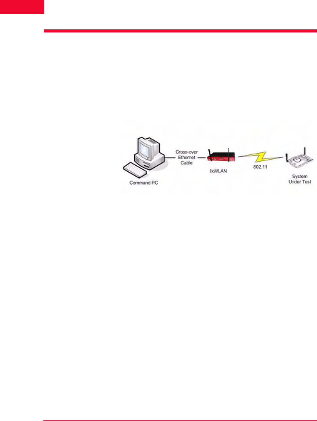
To connect the IxWLAN SED/IXWLAN SED-MR+ chassis to a command PC:
1. Connect one end of the supplied Ethernet crossover cable to the Ethernet port
on the command PC.
2. Connect the other end of the crossover cable to the Mgmt. Port on the chassis,
as shown in Figure 2-1.
Figure 2-1. Connecting the IxWLAN SED/SED-MR+ Chassis to a Command PC
IxWLAN User Guide, Release 6.20 2-3
Installation
Connecting Through an Ethernet Hub or Switch
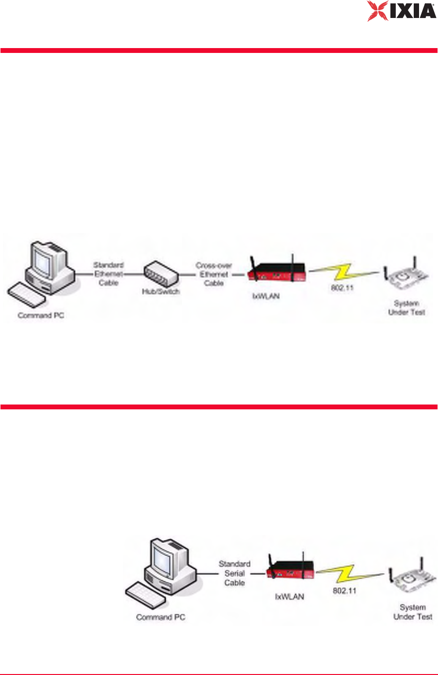
Connecting Through an
Ethernet Hub or Switch
To connect the IxWLAN SED/IXWLAN SED-MR+ chassis through an Ethernet
hub or switch:
1. Connect one end of a standard Ethernet cable (not included) to the Ethernet
port on the command PC. Connect the other end of the cable to the Ethernet
Connector on the Ethernet hub or switch.
2. Connect one end of a standard Ethernet cable to a port on the hub or switch.
Connect the other end of the cable to the Mgmt. Port on the chassis, as shown
in Figure 2-2.
Figure 2-2. Connecting the IxWLAN SED/SED-MR+ Chassis Through an
Ethernet Hub or Switch
The IxWLAN SED/SED-MR+ chassis has a separate data port —Ext. Traffic
Generator—which is used exclusively for the attachment of traffic generators and
has no associated IP stack/address.
Connecting to the Serial Port
A standard straight serial cable is provided with the IxWLAN SED/IXWLAN
SED-MR+ chassis.
To connect to the Serial Port (Figure 2-3):
•Connect the female connector end of the cable to a serial port on the com-
mand PC.
Figure 2-3. Connecting the IxWLAN SED/SED-MR+ Chassis to the Serial Port

Installation
Connecting to the Serial Port
2-4 IxWLAN User Guide, Release 6.20
2

IxWLAN User Guide, Release 6.20 3-1
3Chapter 3: First Setup
This chapter covers the following topics:
•Using the Ethernet Ports on page 3-1.
•Using the Serial Port on page 3-5.
Using the Ethernet Ports
This section covers the following topics:
•Command PC Attached to Port on IxWLAN SED on page 3-1.
•Web-Based User Interface on page 3-3.
•Command Line Interface on page 3-4.
Command PC
Attached to Port on
IxWLAN SED
To configure the Command PC and then access the web-based user interface or
CLI, when the Command PC is attached to the Mgmt Port on the IxWLAN SED:
1. Click Control Panel from the Start menu on the PC.
2. Double-click Network Connections.
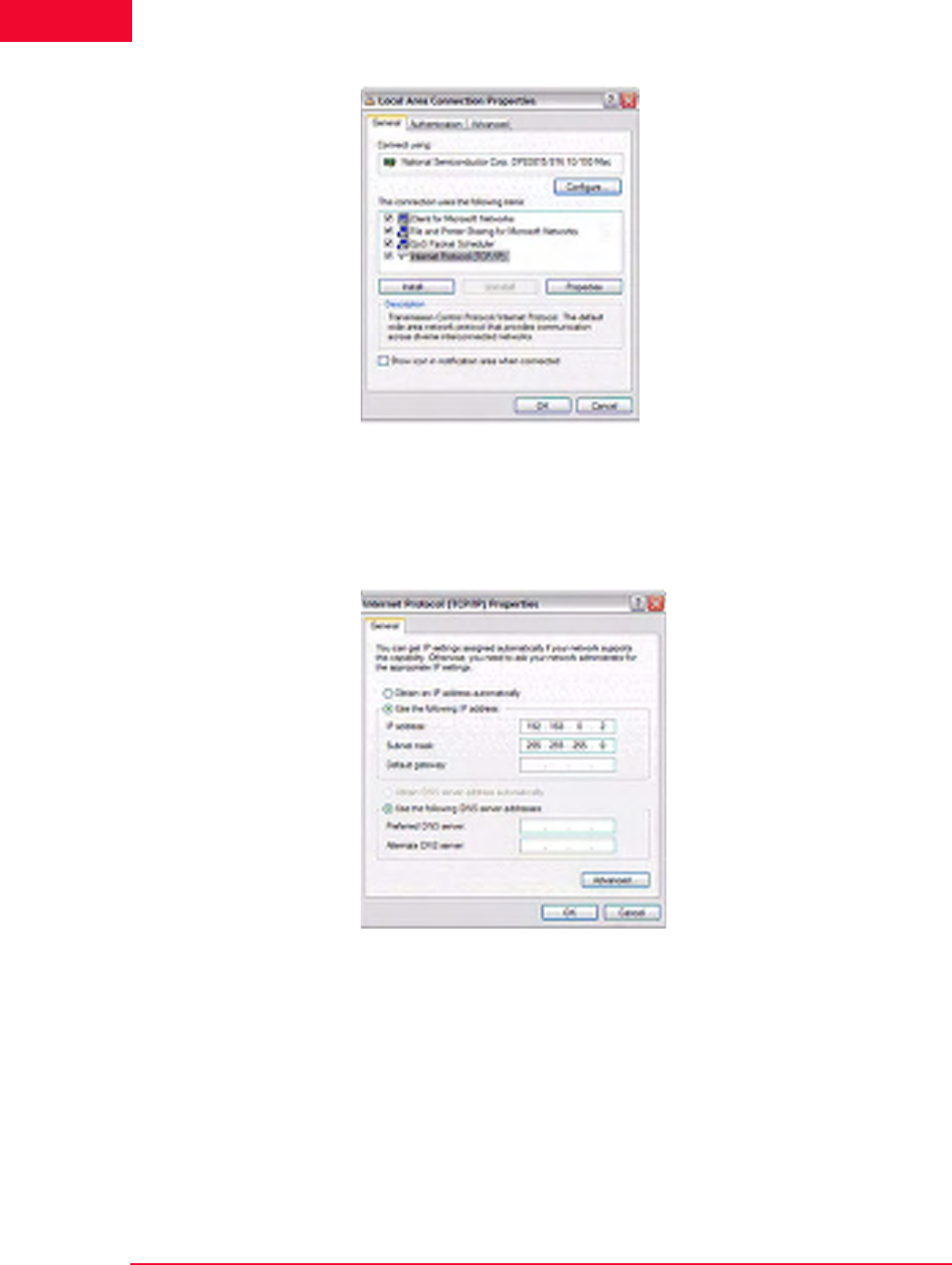
3. Right-click Local Area Connection for the Ethernet controller that is con-
nected to the IxWLAN SED chassis. Select Properties from the right-click
menu and the Local Area Connection Properties dialog opens, as shown in
Figure 3-1 on page 3-2.
First Setup
Using the Ethernet Ports
3-2 IxWLAN User Guide, Release 6.20
3
Figure 3-1. Local Area Connection Properties
4. Click Internet Protocol (TCP/IP).
5. Click the Properties button and the Internet Protocol (TCP/IP) Properties
dialog opens, as shown in Figure 3-2.
Figure 3-2. TCP / IP Properties Dialog
6. Click the Use the following IP address radio button and type the IP address
for the Ethernet connection. Use an IP Address that resides on the same IP
subnet as IxWLAN. For example, use 192.168.0.2 if you are using IxW-
LAN's default IP address 192.168.0.50.
7. Click OK to close the Internet Protocol (TCP/IP) Properties dialog.
8. Click Close to close the Local Area Connection Properties dialog.
You can access IxWLAN using one of the following methods.
IxWLAN User Guide, Release 6.20 3-3
First Setup
Using the Ethernet Ports
Web-Based User
Interface
The command PC must be equipped with:
•Microsoft Windows 2000/XP
•Microsoft Internet Explorer version 6.0 or higher
•Recommended Memory: 256 MB
•Recommended Virtual Memory: 300 MB
•Recommended Processor Speed: PIII 700 MHz
•One of the following ActiveX objects: Msxml2.XMLHTTP or
Microsoft.XMLHTTP. If either of these objects is not found, an alert message
displays: “FATAL ERROR: Error creating ActiveX object XMLHTTP”.
To access the web-based user interface:
1. Start Internet Explorer on the command PC.
2. Select Internet Options from the Tools menu. Click the Settings button and
make sure that the Every Visit to Page radio button is clicked in the Settings
dialog. This step is needed only the first time you use the web-based user
interface.
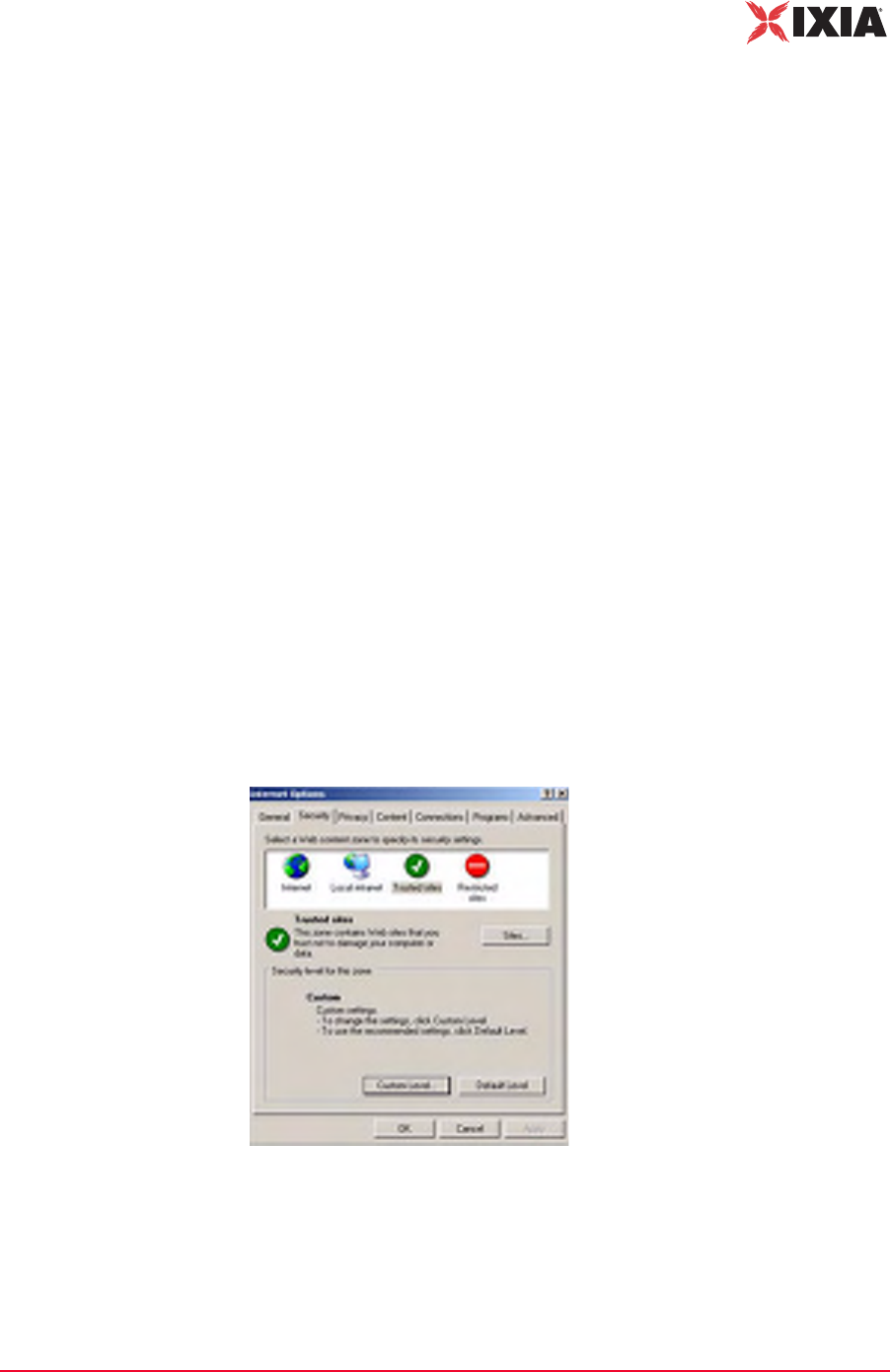
3. Add the IxWLAN IP Address to your list of Trusted Sites and set the security
level to Low for trusted sites.
•Select the Security tab in the Internet Options dialog.
•Select the Trusted sites icon (Figure 3-3).
•Set the Security level for this zone to Low. If the security level for the zone
is not Low, set the default level to Low.
Figure 3-3. Internet Options
•Click the Sites… button.
•In the Trusted sites dialog, type the IxWLAN IP address in the Add this
Web site to the zone field and click the Add button.
First Setup
Using the Ethernet Ports
3-4 IxWLAN User Guide, Release 6.20
3
•Click OK in the Trusted sites dialog.
•Click OK in the Internet Options dialog.
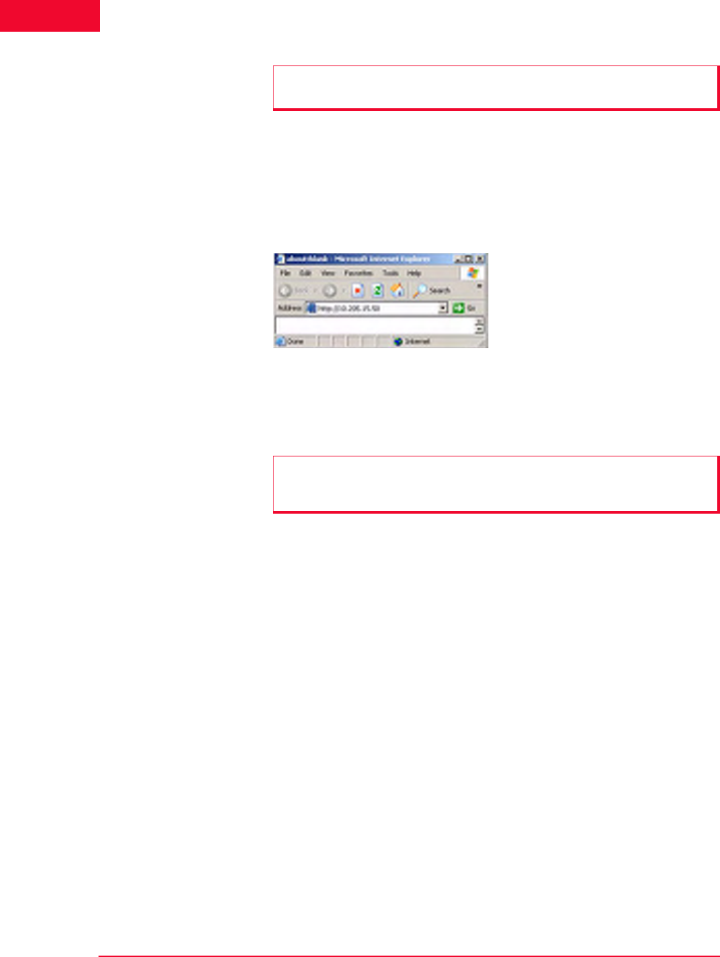
Use the IxWLAN default IP address 192.168.0.50 for the first setup, as shown in
Figure 3-4.
Figure 3-4. First Setup Example
For further information about how to use the web-based user interface, please
refer to Chapter 4, The Web-Based User Interface.
Command Line
Interface
You can use a PC that is connected via Telnet to access the CLI. To establish a
Telnet connection, use the IxWLAN default IP address 192.168.0.50 for the first
setup.
C:\>telnet 192.168.0.50
For more information about how to use the CLI, please refer to Chapter 5, The
Command Line Interface (CLI).
NOTE: Make sure that the Require server verification (https:) checkbox for all
sites in this zone is not clicked.
NOTE: If pop-up blocker software is installed on your system, the splash page
opens an error message. Please refer to Chapter 8, Troubleshooting for further
information.
IxWLAN User Guide, Release 6.20 3-5
First Setup
Using the Serial Port
Using the Serial Port
If the command PC is connected to the IxWLAN chassis via the serial port, the
web-based user interface is not available.
To configure the Command PC and then access the CLI:
1. On the Command PC, start a terminal-emulation program such as HyperTer-
minal.
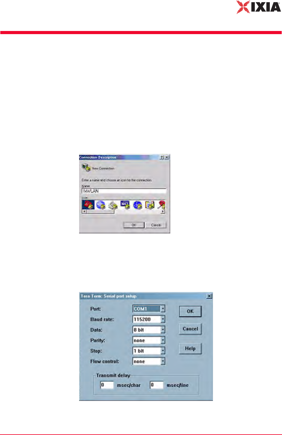
2. In the Connection Description dialog, type a name for the connection in the
Name field (for example, IxWLAN).
3. Choose an icon for the connection, then click OK and the Connect To dialog
opens, as shown in Figure 3-5.
Figure 3-5. Connect To Dialog
4. From the Connect Using list box, select the COM port that is connected to
IxWLAN; then click OK and the COM Properties dialog opens, as shown in
Figure 3-6.
Figure 3-6. COM Properties Dialog

First Setup
Using the Serial Port
3-6 IxWLAN User Guide, Release 6.20
3
5. Set the COM port settings as shown in Figure 3-6 on page 3-5:
•Bits per second: 115200 for IxWLAN SED
•Data bits: 8
•Parity: None
•Stop bits: 1
•Flow control: None
6. Click OK to close the COM properties dialog.
The POST messages appear on the HyperTerminal screen a few seconds after
IxWLAN is connected to the power source.
Attached TCP/IP interface to fei0
Attaching network interface lo0...done.
Loading... 11443040
Starting at 0x308000...
Reading Configuration File "/ata0a/config".
Configuration file checksum: 23596 is good
fei0 loaded
Base address = f0200000, irq 37
Attach AR5212 0x13 0x1dbb5728
wlan0 revisions: mac 5.6 phy 4.1 analog 1.7 eeprom 3.4
ar0 loaded
Attaching interface lo0...done
VxWorks
Copyright 1984-2002 Wind River Systems, Inc.
CPU: Ampro RB 800
Runtime Name: VxWorks
Runtime Version: 5.5.1
BSP version: 1.0/3
Created: Apr 7 2006, 11:51:55
WDB: Ready.
IxWLAN Init:Mgmt LAN MAC 00:08:9B:80:2A:1A
IxWLAN Init:Data LAN MAC 00:08:9B:80:2B:1B
cn505: b0 d3 f0, B0 b8810001 B2 b8810101
Starting WLAN ...
Starting quick passive scan ...
Passive scanning 5 GHz 54Mbps (802.11a) channels for 7
seconds...
Ixia IxWLAN Ready
To open the IxWLAN logon prompt, press the ENTER key:
IxWLAN login:

IxWLAN User Guide, Release 6.20 3-7
First Setup
Using the Serial Port
When the IxWLAN logon prompt opens, use the information in Chapter 5, The
Command Line Interface (CLI) to log on and access the CLI.

First Setup
Using the Serial Port
3-8 IxWLAN User Guide, Release 6.20
3

IxWLAN User Guide, Release 6.20 4-1
4Chapter 4: The Web-Based User
Interface
This chapter covers the following topics:
•Startup and Login on page 4-1.
•Choosing and Creating a Scenario on page 4-3.
•Using the Main Page on page 4-14.
•vSTA Side Bar on page 4-25.
•IxWLAN Side Bar on page 4-40.
•Monitors Side Bar on page 4-55.
•Event Log Side Bar on page 4-63.
•Reports Side Bar on page 4-66.
•Configuration Side Bar on page 4-71.
•Menus and Tool Bars on page 4-78.
Startup and Login
Some of the dialogs shown in this chapter are feature key dependent. For more
information, please refer to Feature Key Dependent Parameters on page 1-13.
To start the IxWLAN software and log on:
1. Start Internet Explorer.
2. Type the IP address of the IxWLAN chassis in the URL address field of the
browser (for example, http://10.205.15.50).
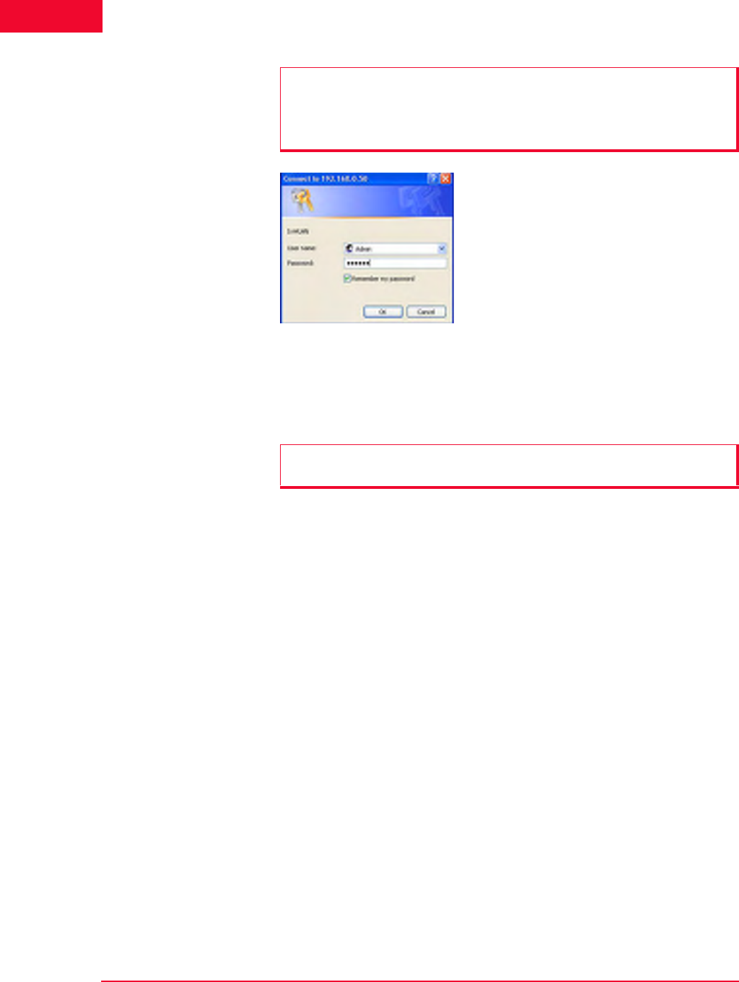
3. Type your user name and password, as shown in Figure 4-1.
NOTE: If WPA/RSN features are enabled, IxWLAN checks for encryption
hardware on startup. If no encryption hardware is found, a dialog with the
following message opens: “WPA Features have been disabled! IxWLAN is
licensed for WPA, but no encryption hardware was found.”
Please contact the Ixia Customer Support when this dialog opens.
The Web-Based User Interface
Startup and Login
4-2 IxWLAN User Guide, Release 6.20
4
Figure 4-1. Startup and Login
4. Click OK to access the IxWLAN web server.
5. After successful logon, a splash page opens for a few seconds.
NOTES:
•The default user name is Admin.
•The default password is IxWLAN.
The user name and password are case-sensitive.
NOTE: If pop-up blocker software is installed on your system, this splash page
opens an error message. For details, see Chapter 8, Troubleshooting.
IxWLAN User Guide, Release 6.20 4-3
The Web-Based User Interface
Choosing and Creating a Scenario
Choosing and Creating a
Scenario
This section covers the following topics:
•Choosing How to Begin on page 4-3.
•Creating an Internal Mode/Ping Test on page 4-6.
•Creating an External Mode Test on page 4-7.
•Running a Test on page 4-9.
Choosing How to
Begin
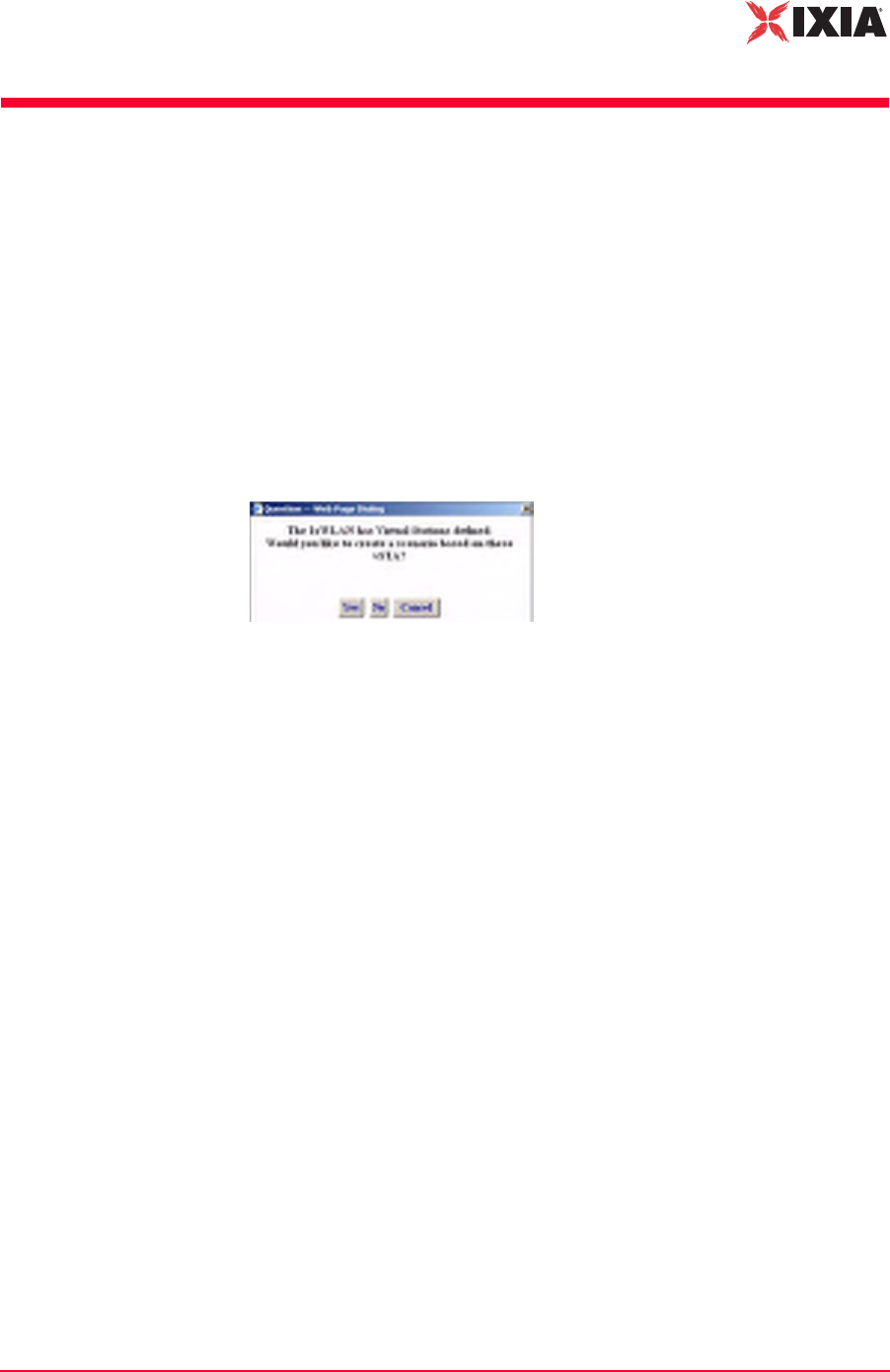
When IxWLAN already contains virtual station definitions, the dialog shown in
Figure 4-2 opens.
Figure 4-2. Choosing How to Begin
•Click Yes to build a scenario in the user interface that is based on the virtual
stations that are already defined in IxWLAN.
•Click No to delete the virtual station definitions and create a new, empty sce-
nario.
•Click Cancel to retain the virtual stations in IxWLAN but not create a new,
empty scenario.
When the main page opens, you can view the Scenario Summary Report, Group
Summary Report, and Event Log for these existing virtual stations.
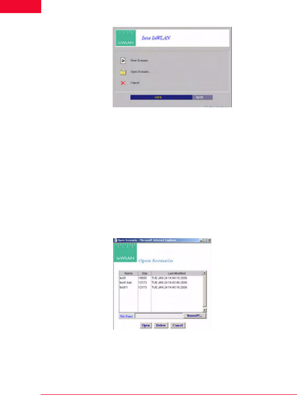
Figure 4-3 on page 4-4 opens when there are no virtual station definitions in
IxWLAN and the welcome screen has not been disabled in the UI Configuration
(For more information, please refer to Configuration->Preferences on page 4-
77).
The Web-Based User Interface
Choosing and Creating a Scenario
4-4 IxWLAN User Guide, Release 6.20
4
.
Figure 4-3. Screen Opening When There Are No Virtual Stations Definitions
•Click New Scenario to continue to the main page and create a new scenario.
•Click Open Scenario to choose from a list of scenario files that have already
been created. When you open an existing scenario, IxWLAN information is
already stored with the scenario file.
•Click Cancel to exit the dialog. You can create a new scenario or open an
existing scenario in the main page.
•Unselect the Show On Startup checkbox if you do not want to show this
screen each time you access the IxWLAN web server. You can restore this
screen in the UI Configuration dialog (For more information, please refer to
Configuration->Preferences on page 4-77).
When you click Open Scenario, the Open Scenario dialog opens, as shown in
Figure 4-4.
Figure 4-4. Open Scenario Dialog
The list box shows a list of scenario files in IxWLAN. Click the BrowsePC…
button to show scenario files stored on the command PC. Click a file name in the
list of scenario files.
•Click the Open button to open the selected scenario file and continue.
IxWLAN User Guide, Release 6.20 4-5
The Web-Based User Interface
Choosing and Creating a Scenario
•Click the Delete button to delete the selected file.
•Click the Cancel button to close this dialog without opening a scenario file.
You can create a new scenario or open an existing scenario in the main page.
Main Page
Figure 4-5 shows the format of the main page that opens after you select any of
the options in the start-up dialogs. This page looks differently, depending on
whether you are running the web-based user interface on a SED or on a SED-
MR+ chassis. Figure 4-5 shows the appearance of the IxWLAN SED-MR+ main
page. For further details on the differences in the appearance of the main page on
the two chassis, see Using the Main Page on page 4-14.
Figure 4-5. Main Page
The content of this page differs depending on whether you create a new scenario,
open an existing scenario, or cancel/close any of the start-up dialogs. Figure 4-5
presents an existing scenario, with two groups defined.
If you have successfully opened a scenario file or chosen to use one that is
already defined in IxWLAN, you can continue with the testing functions that are
available in the menus and tool bars. For more information, please refer to
Running a Test on page 4-9.
NOTE: If no scenario has been created, the page is blank (No Scenario
Defined).
The Web-Based User Interface
Choosing and Creating a Scenario
4-6 IxWLAN User Guide, Release 6.20
4
If you click the Cancel button or the Create New Scenario button, you must cre-
ate a new scenario that contains one or more group(s) of one or more virtual sta-
tion(s).
Creating an Internal
Mode/Ping Test
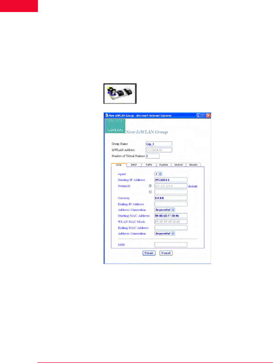
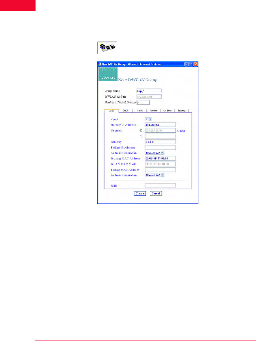
For a simple internal mode/ping test:
1. Click New Group from the vSTA side bar to open the New IxWLAN Group
dialog, as shown in Figure 4-6.
.
Figure 4-6. New IxWLAN Group Dialog
2. If you want IxWLAN to dynamically acquire IP addresses, select DHCP
from the Address Generation drop-down list box. Otherwise, type an IP
address in the Starting IP Address field to define the starting IP address to be
used by virtual stations that are created in this scenario. Virtual stations are
created with unique IP addresses, sequentially or randomly, based on this
starting IP address.
If you set the SSID, you can create a group with a SSID.
IxWLAN User Guide, Release 6.20 4-7
The Web-Based User Interface
Choosing and Creating a Scenario
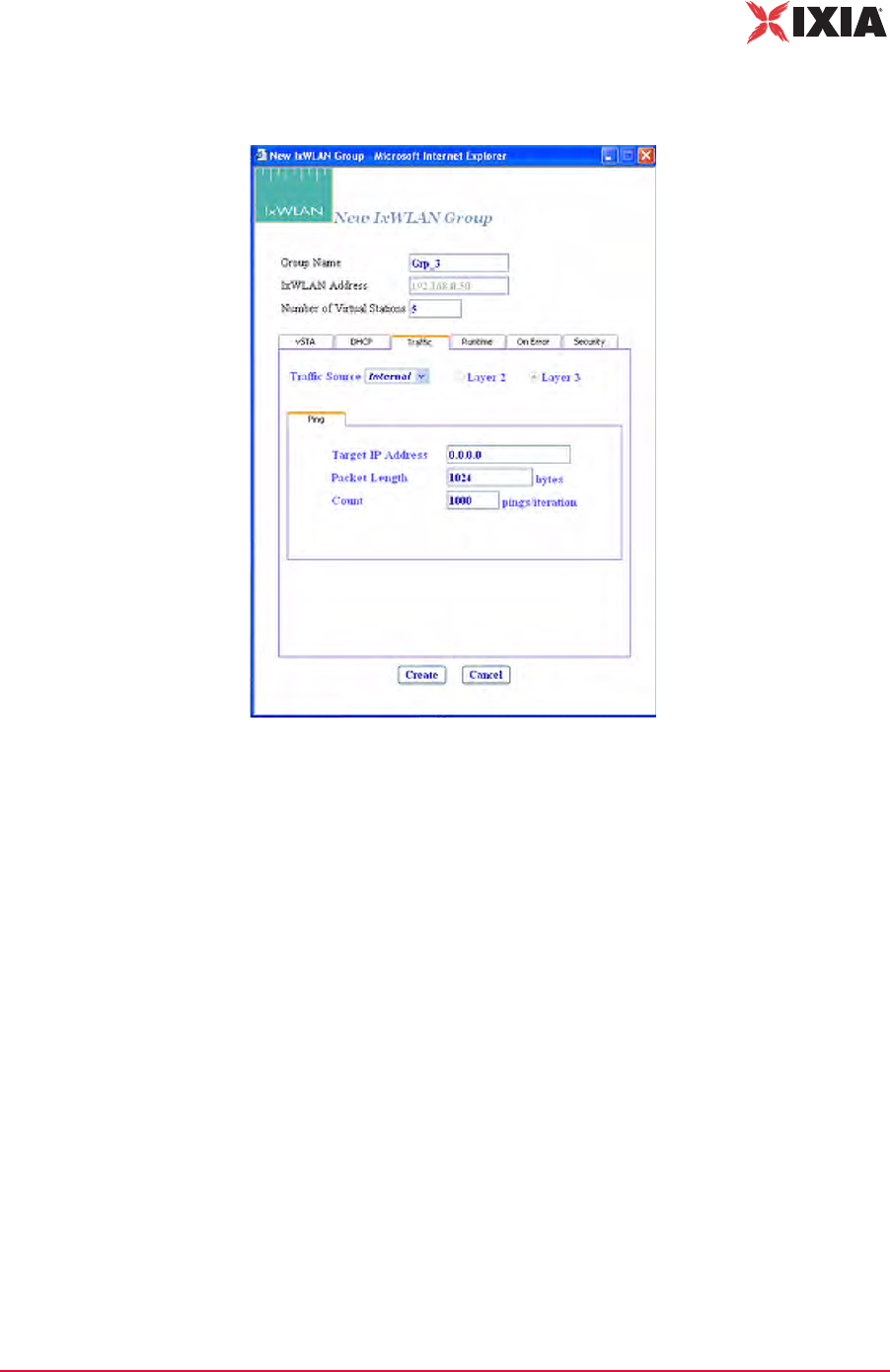
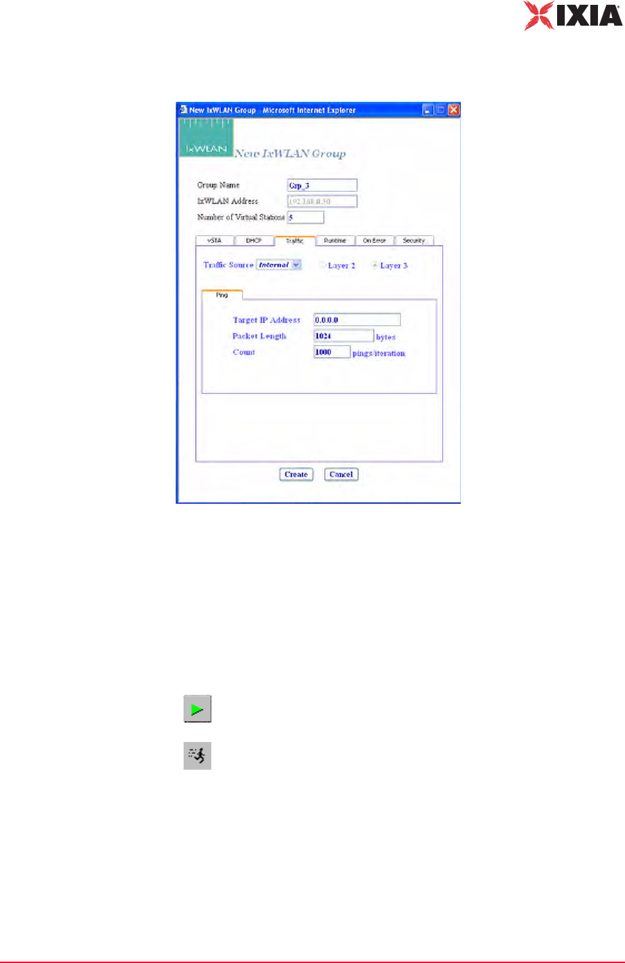
3. Select the Traffic tab, as shown in Figure 4-7.
Figure 4-7. Traffic Tab
4. Make sure that the Target IP Address field is set to the address of a target
server to be pinged. The default IP address (0.0.0.0) shown in this example
screen must be replaced by a valid IP address (for example, 10.205.15.95).
Click the Create button to create a group with five virtual stations. For more
information on defining and editing groups and virtual stations in a scenario,
please refer to vSTA->New Group on page 4-26.
5. Please refer to Running a Test on page 4-9 for procedures needed to run this
test.
Creating an
External Mode Test
For an external mode test, a third-party load generator outside IxWLAN must be
set up to provide the traffic to be forwarded to the System Under Test.
1. Use the documentation provided by the manufacturer to set up the load gener-
ator.
The Web-Based User Interface
Choosing and Creating a Scenario
4-8 IxWLAN User Guide, Release 6.20
4
2. Select New Group from the vSTA side bar to open the New IxWLAN Group
dialog, as shown in Figure 4-8.
Figure 4-8. Select New Group from vSTA Side Bar
3. For layer 3, the source IP on your load generator must match the starting IP
address assigned to the first vSTA on IxWLAN. For layer 2, the source MAC
on your load generator must match the starting MAC address assigned to the
first vSTA on IxWLAN.
IxWLAN User Guide, Release 6.20 4-9
The Web-Based User Interface
Choosing and Creating a Scenario
4. Select the Traffic tab, as shown in Figure 4-9.
Figure 4-9. Traffic Tab
5. Select External in the Traffic Source field. Click the Layer 2 radio button to
capture frames based on an 802.3 MAC source address. Click the Layer 3
radio button to capture frames based on an IP source address. A target IP
address is not needed for an external mode test.
6. Click the Create button to create the scenario for an external mode test.
Running a Test
If you have not joined with a System Under Test, the dialog shown in Figure 4-10
on page 4-10 opens.
Allows you to run the scenario/test for all groups and all virtual
stations in a scenario.
Allows you to run a test for selected virtual stations or groups.

The Web-Based User Interface
Choosing and Creating a Scenario
4-10 IxWLAN User Guide, Release 6.20
4
Figure 4-10. Running a Test without Joining a SUT
Click Yes to open the Select System Under Test dialog and join with the System
Under Test.
You can use any of the following methods to open the System Under Test dialog,
shown in Figure 4-11 on page 4-11:
1. Click Yes in the You are not joined with the SUT dialog shown in Figure 4-
10.
2. Click the SUT icon in the System Under Test status tool bar at the top of
the main window.
NOTE: It is always necessary to join with a System Under Test before running a
test (internal or external). If there are no SSIDs listed in the main page, the
Select System Under Test dialog does not show any systems to join. If this is
the case, click the Rescan button in the main page to instruct IxWLAN to look
for systems to test.

IxWLAN User Guide, Release 6.20 4-11
The Web-Based User Interface
Choosing and Creating a Scenario
3. Click the Select SUT button in the IxWLAN side bar.
Figure 4-11. Select SUT Dialog
If you have created a new scenario and have not saved it using the Save Scenario
option in the File menu, the dialog shown in Figure 4-12 opens, asking you to
save the scenario.
Figure 4-12. Save Scenario Dialog

The Web-Based User Interface
Choosing and Creating a Scenario
4-12 IxWLAN User Guide, Release 6.20
4
Click Yes to open the Save Scenario dialog and save the scenario file, as shown
in Figure 4-13.
Figure 4-13. Save Scenario File
Type a name in the File Name field.
•Click the Save (IxWLAN) button to save the scenario in the IxWLAN flash
file system.
•Click the Save(PC) button to save the scenario on the command PC. A stan-
dard save dialog opens, as shown in Figure 4-14.
Figure 4-14. Save HTML Doc Dialog
NOTE: Do not use colon (:), asterisk (*), question mark (?), quotes (“ “), less-
than/greater than signs (< >), vertical bar (|), or spaces in a file name.

IxWLAN User Guide, Release 6.20 4-13
The Web-Based User Interface
Choosing and Creating a Scenario
Type a name in the File Name field.
A disk drive specification (for example, C:/, D:/) is optional. Click the Save but-
ton to save the scenario at the designated location on the command PC.
The virtual stations start running a few seconds after the scenario is saved. As the
test runs, you can see the “Run State” in the group grid go through the 802.11
states: configure, starts, authenticate, associate, and run. When an internal mode/
ping test is complete, the Run State shows Done.
NOTE: Do not use colon (:), asterisk (*), question mark (?), quotes (“ “), less-
than/greater than signs (< >), vertical bar (|), or spaces in a file name.
NOTE: Any interaction with a running test can affect the operation of the test,
which may result in skewed statistics.

The Web-Based User Interface
Using the Main Page
4-14 IxWLAN User Guide, Release 6.20
4
Using the Main Page
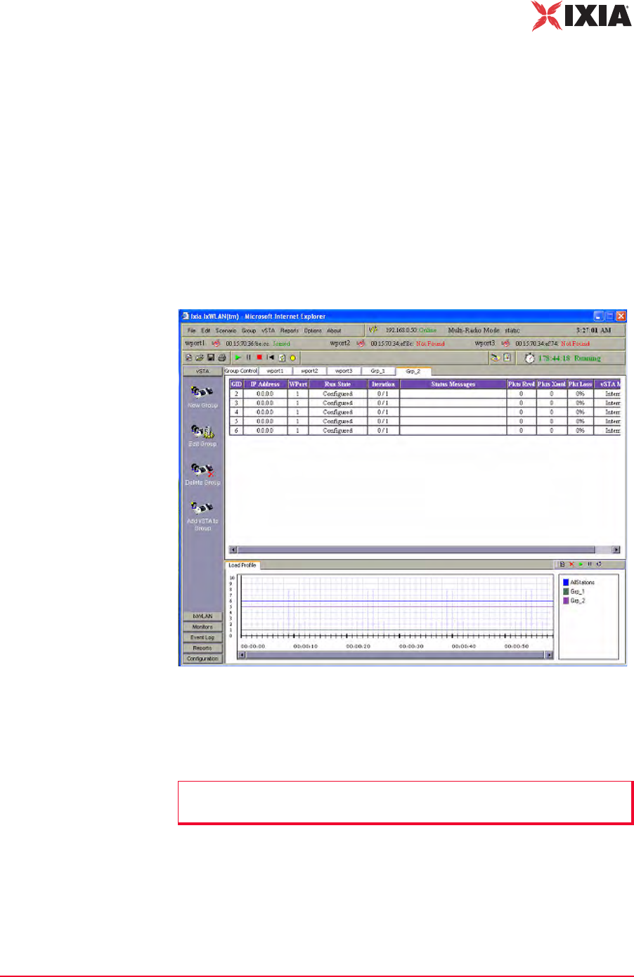
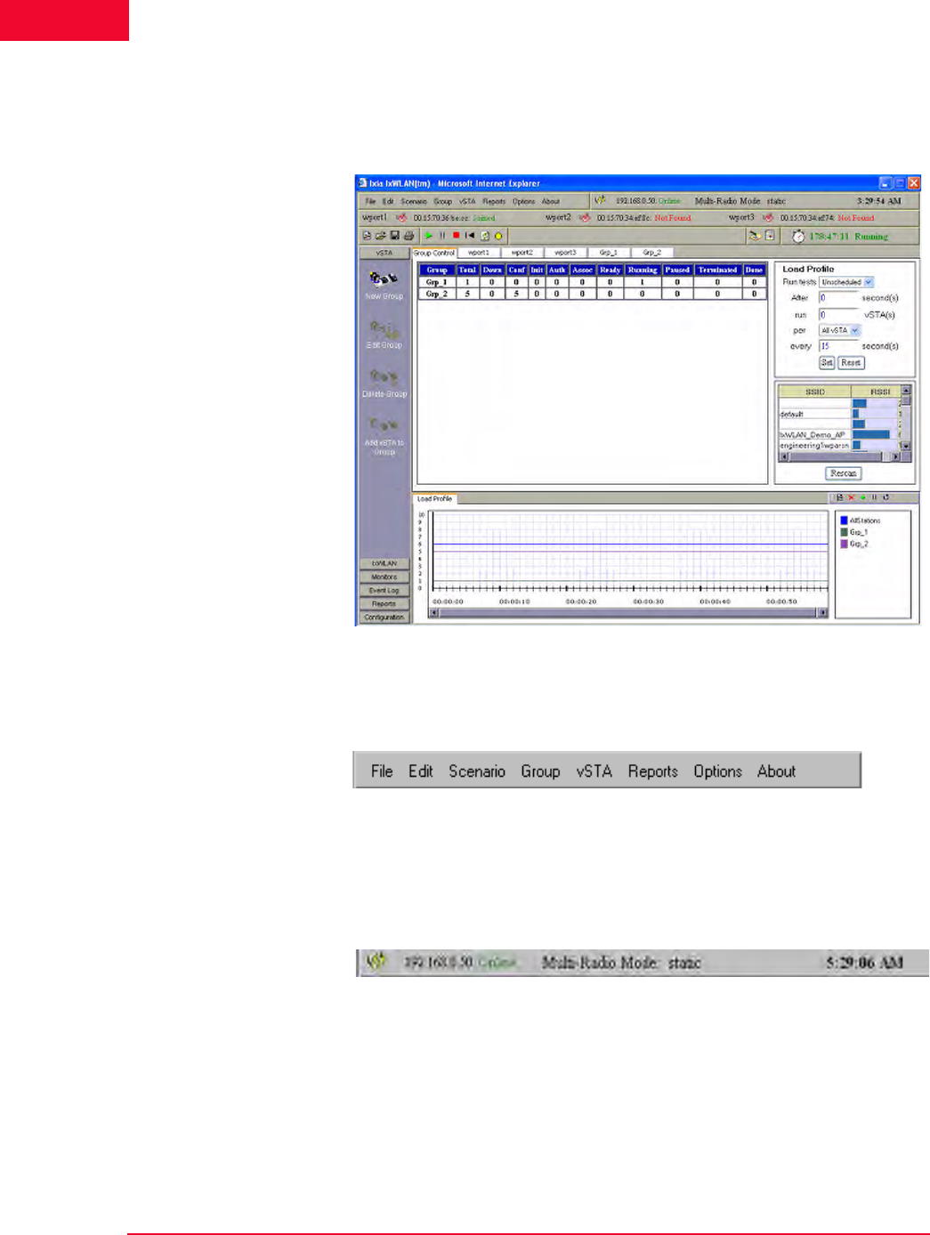
Figure 4-15 shows the general format of the main page, as it displays on an IxW-
LAN SED-MR+ chassis. It illustrates a scenario with two virtual station groups
defined and a group tab (Grp_2) selected.
Figure 4-15. IxWLAN SED-MR+ Main Page
NOTE: The appearance of the main IxWLAN window differs depending on the
type of chassis used to run the web-based interface:
•In the main window of the IxWLAN SED chassis, the BSSIDs for the other
two wports, which are available in the IxWLAN SED-MR+ chassis main win-
dow, are disabled, appearing dimmed, as well as the corresponding SUT-
selection buttons.
•The wport tabs for the other two wports do not appear in the main window of
the IxWLAN SED chassis.
IxWLAN User Guide, Release 6.20 4-15
The Web-Based User Interface
Using the Main Page
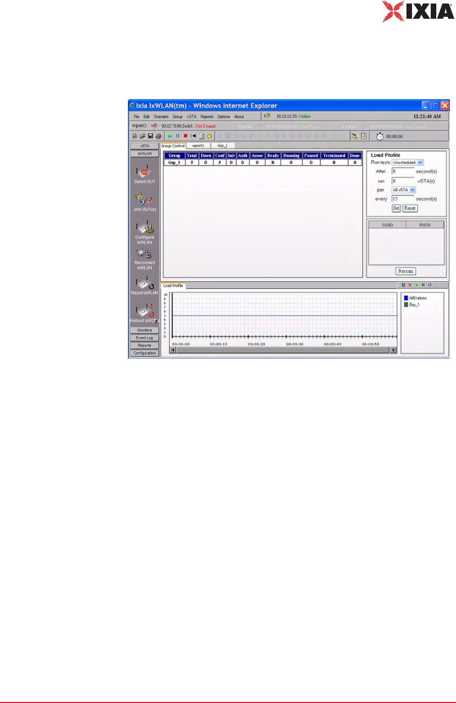
For the IxWLAN SED chassis, the main window has a similar appearance,
except for the two other wports, which are dimmed. Figure 4-16 shows a scenario
with one virtual station group defined and the Group Control tab selected.
Figure 4-16. IxWLAN SED Main Page
The Web-Based User Interface
Using the Main Page
4-16 IxWLAN User Guide, Release 6.20
4
When the Group Control tab is selected, the main page opens the Load Profile
and a list of devices that have been discovered (if any) in a scan, as shown in
Figure 4-17.
Figure 4-17. Load Profile and List of Devices
Menu tool bar: The top-left tool bar of the main page is a drop-down menu bar
of all IxWLAN functions (Figure 4-18).
Figure 4-18. Menu Tool Bar
Status tool bar: The top-right tool bar shows the status of IxWLAN, the multira-
dio mode (Static or Dynamic), and the current time on the command PC (Figure
4-19).
Figure 4-19. Status Tool Bar
The status (for example, Online) next to IxWLAN IP Address indicates the cur-
rent status of IxWLAN with the web-based user interface. This status may inter-
mittently show Busy or Offline. If the Busy or Offline status displays frequently
or for extended periods of time, check the Polling Interval and Polling Timeout
values in the Configure IxWLAN dialog. The Multi-Radio Mode indicator on the
tool bar shows the currently set multi-radio mode (static or dynamic). The
default setting for the multi-radio mode indicator is static. The multi-radio mode
can be changed in the Configure IxWLAN dialog. Please refer to IxWLAN-
IxWLAN User Guide, Release 6.20 4-17
The Web-Based User Interface
Using the Main Page
>Configure IxWLAN on page 4-44 and to IxWLAN Busy or Not Responding on
page 8-5.
System Under Test status tool bar: It is located under the Menu and Status tool
bars and shows the BSSID(s) and buttons to choose SUT(s) for specific wports.
The status (for example, Not Found) next to the BSSID/MAC address indicates
the current status of IxWLAN with a System Under Test (Figure 4-20).
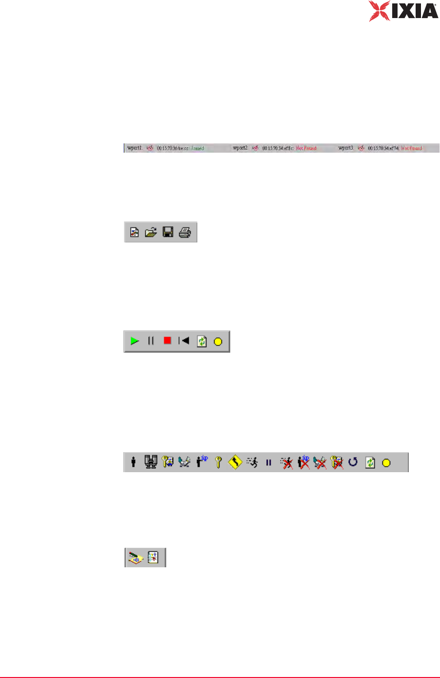
Figure 4-20. SUT Status Tool Bar
File tool bar: This tool bar is used to create, open, save, and print scenarios
(Figure 4-21).
Figure 4-21. File Tool Bar
Scenario tool bar: The buttons in this section of the tool bar can be used to run,
pause, stop, restart, refresh, or quiesce the entire scenario of all virtual stations
(Figure 4-22).
Figure 4-22. Scenario Tool Bar
vSTA tool bar: The buttons in this tool bar are used to start, authenticate, associ-
ate, acquire an IP, run, pause, release an IP, stop, disassociate, de-authenticate,
restart, refresh, or quiesce selected virtual stations or groups of virtual stations
(Figure 4-23).
Figure 4-23. vSTA Tool Bar
Reports tool bar: The buttons in this tool bar are used to view reports and the
event log (Figure 4-24).
Figure 4-24. Reports Tool Bar

The Web-Based User Interface
Using the Main Page
4-18 IxWLAN User Guide, Release 6.20
4
Test Clock: The clock icon and time (hh:mm:ss) immediately adjacent to the
Reports tool bar shows the elapsed duration of a test that is in progress or the
most recent test that completed (Figure 4-25).
Figure 4-25. Test Clock
Side Bar Buttons: The side bar buttons are used to select vSTA, IxWLAN,
Monitor, Report, Event Log, and Configuration functions in the web-based user
interface (Figure 4-26).
Figure 4-26. Side Bar Buttons
Note the down-arrow buttons at the bottom of the IxWLAN and Reports side
bars. These arrows indicate additional functions or information in the down side
of the side bar displayed. When you click the down-arrow button, the additional
information displays and an up-arrow button is shown at the top of the side bar.

IxWLAN User Guide, Release 6.20 4-19
The Web-Based User Interface
Using the Main Page
Group Control Grid If the Group Control tab is selected, the table shows the status of each group and
its associated virtual stations, as shown in Figure 4-27.
Figure 4-27. Group Status
Group: Shows the name of each group. The name is assigned in the New IxW-
LAN Group dialog (For more information, please refer to vSTA->New Group on
page 4-26).
The remaining fields in the group line are counters that show the state of each
group’s virtual stations during a test.
Total: Shows the total number of virtual stations in each group.
Down: Shows the total number of virtual stations in a group that have not been
configured in IxWLAN and are in a down state.
Conf (Configured): Shows the total number of virtual stations in each group that
have been configured in IxWLAN.
Init (Initialized): Shows the total number of virtual stations in each group that
have been started in IxWLAN.
Auth (Authenticated): Shows the total number of virtual stations in each group
that have been 802.11 authenticated with the System Under Test.
Assoc (Associated): Shows the total number of virtual stations in each group that
have been 802.11 associated with the System Under Test.
Ready: Shows the total number of virtual stations in each group that are ready to
run.
Running: Shows the total number of virtual stations in each group that are cur-
rently performing an operation defined by the scenario. The operation that is
being performed depends on whether the virtual stations are configured for inter-
nal or external traffic generation.
Paused: Shows the total number of virtual stations in each group that have
paused in their execution.
Terminated: Shows the total number of virtual stations in each group that have
been ended. These virtual stations must be reset before they can be used again.
Done: Shows the total number of virtual stations in each group that have com-
pleted their run of an internal mode/ping test. This field is not to be incremented
for virtual stations that are running an external mode test or an internal mode test
with infinite iterations.

The Web-Based User Interface
Using the Main Page
4-20 IxWLAN User Guide, Release 6.20
4
wport Tabs: Each wport has its own tab. When a wport tab is selected, the table
displays details on the vSTAs corresponding to the respective wport. The table
columns are the same as for the Groups tabs, except for the wport column.
Group Tabs: Each group defined in the scenario has its own tab. When an indi-
vidual group tab is selected, the table displays details of each virtual station in the
group, as shown in Figure 4-28.
Figure 4-28. Group Tabs
GID: The global ID is a unique ID that is assigned by IxWLAN to each virtual
station in a scenario group. It is an unique ID across all groups in IxWLAN. The
GID is the vSTA ID.
IP Address: Shows each virtual station's IP Address.
WPort: Shows the wport on which the vSTA resides
Run State: Shows the current state of each virtual station in the scenario group
(that is, Initializing, Authenticating, Authenticated, Associating, and so on).
Iteration: The two numbers in this column show the current iteration of the test
that a virtual station is running or has completed and the number of iterations that
are configured for the virtual station (for example, 5/10 = 5 iterations have been
completed/10 iterations are to be run). These numbers can be a value in the range
zero (0) to 9999 or Infinite.
Status Messages: Shows the status and/or the error messages returned by IxW-
LAN for each virtual station in the scenario group. For more information about
the messages that can be shown in this column, please refer to Appendix E, Error
and Status Messages.
Pkts Rcvd: Shows the total number of packets received by each virtual station in
this group.
Pkts Xmtd: Shows the total number of packets transmitted by each virtual station
in this group.
Pkt Loss: Shows the percentage of packet loss for each virtual station in this
group.
vSTA Mode: Shows the traffic generation mode (Internal or External) of each vir-
tual station in the scenario group.
NOTE: While in the wport tab view, the Edit and Group menu items are
dimmed.
IxWLAN User Guide, Release 6.20 4-21
The Web-Based User Interface
Using the Main Page
You can select one or more line items/virtual stations in the table and choose a
menu item or tool bar button to execute a command for an individual or multiple
virtual stations.
You can double-click a virtual station line item in the table to open the Edit Vir-
tual Station dialog. For more information about this dialog, please refer to vSTA-
>Add New vSTA to Group on page 4-39.
You can right-click the selected virtual stations to open the vSTA menu. For
more information about the selections in this menu, please refer to vSTA Menu on
page 4-89.
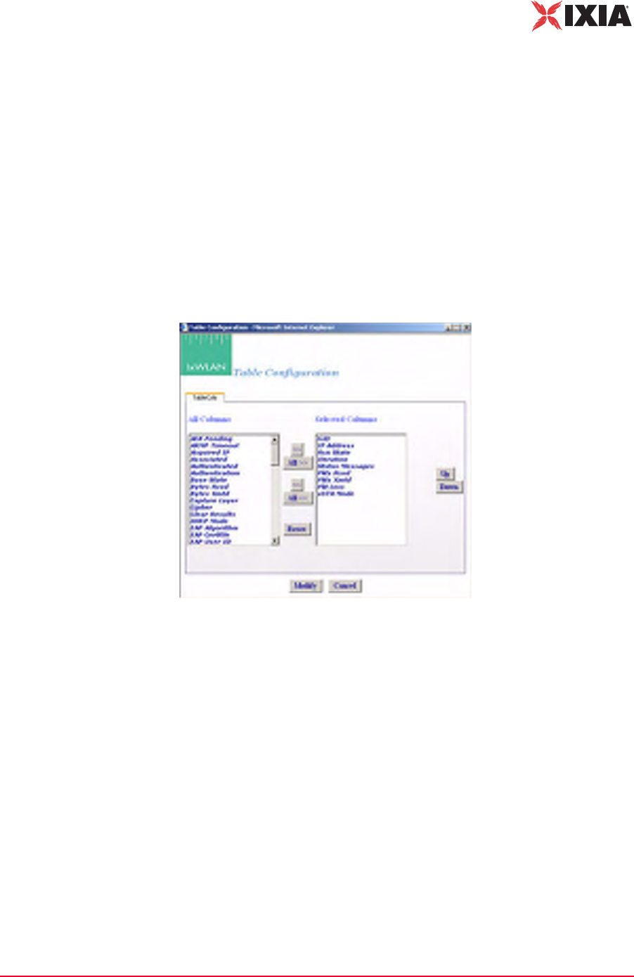
Group Tab Columns: Within a group, you can double-click the table heading to
configure the displayed columns, as shown in Figure 4-29.
Figure 4-29. Group Tab Columns
Select one or more items in the All Columns list box and click the [>>] button to
move them to the Selected Columns list box. Click the Modify button to add the
columns to the group table. Click the Reset button to return the columns to their
default setting.
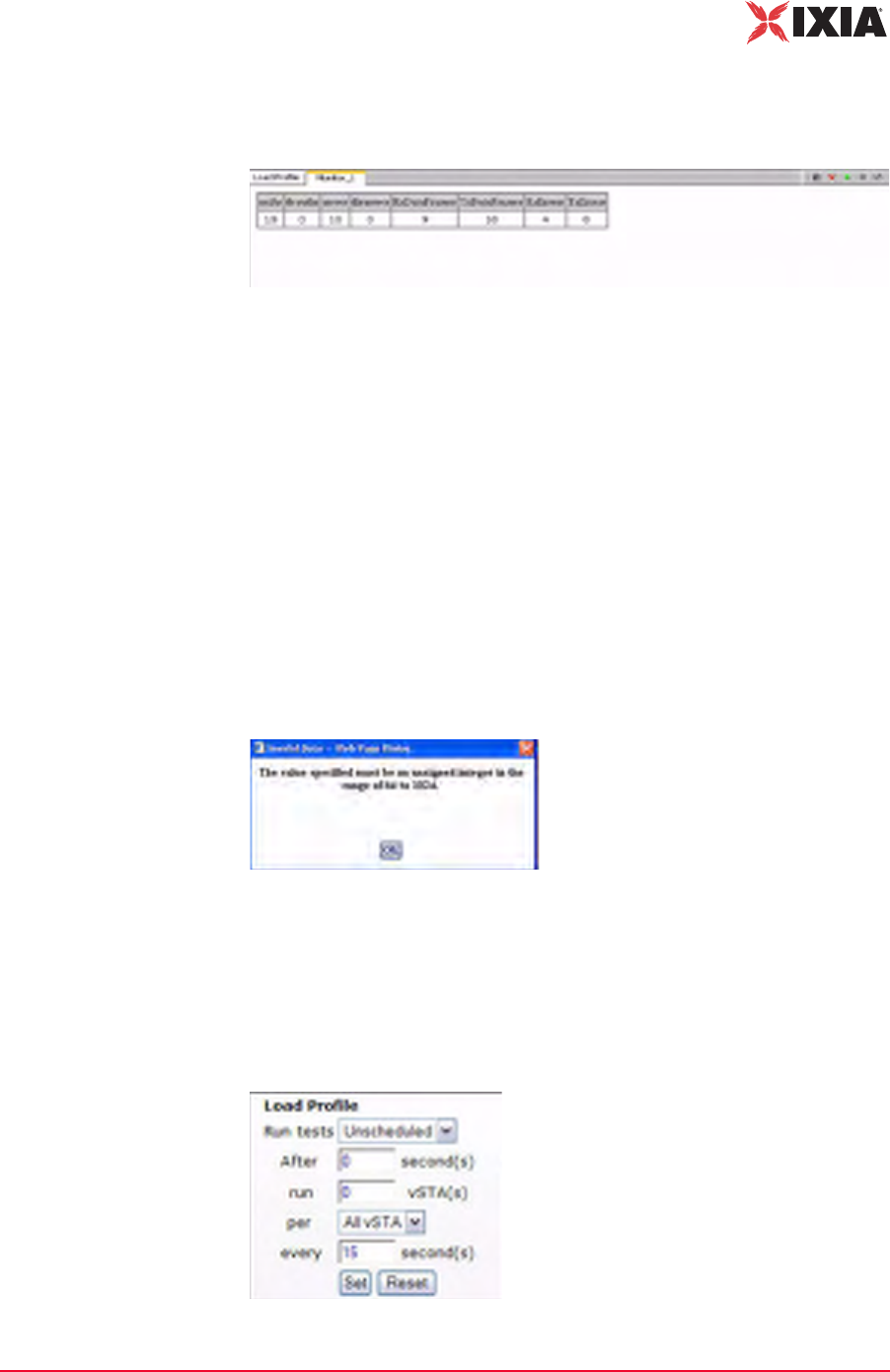
Load Profile The Load Profile section of the page can be used to automatically execute scenar-
ios at scheduled intervals, as shown in Figure 4-30 on page 4-22.

The Web-Based User Interface
Using the Main Page
4-22 IxWLAN User Guide, Release 6.20
4
Figure 4-30. Load Profile
When automatic scheduling is defined, the grid in the down side of the Schedul-
ing/Group table charts the status of each virtual station over the period of the test.
For further information about using this feature please refer to Using Load
Profiles on page 4-23.
Systems to Test In the down side of the Load Profile, the main page shows a list of systems and
their signal strength in relationship to IxWLAN, as shown in Figure 4-31.
Figure 4-31. System to Test
Click the Rescan button to instruct IxWLAN to rescan for all systems. The
devices shown in this list box are shown in the Select System Under Test dialog,
that allows you to choose a system to test.
Load Profile/Monitor
Graphs
The bottom half of the web page is reserved for charts that graphically show a
load profile and monitor test results. If selected, the Load Profile tab allows you
to view the loading profile based on an active Load Profile, as shown in Figure 4-
32.
Figure 4-32. Load Profile / Monitor Graphs
For more information about how to set up a Load Profile, please refer to Using
Load Profiles on page 4-23.
IxWLAN User Guide, Release 6.20 4-23
The Web-Based User Interface
Using the Main Page
If there are multiple monitors defined, use the horizontal tabs at the top of this
section to select and view each monitor, as shown in Figure 4-33.
Figure 4-33. Multiple Monitors
A maximum of four monitors can be defined in each scenario. The tool bar in the
top right corner of the monitor area allows you to define a new monitor, delete a
monitor, run a paused monitor, pause a running monitor, and clear a monitor’s
view. For more information about this section of the page, please refer to
Monitors Side Bar on page 4-55.
Range Checking/
Error Messages
In the dialogs described later in this chapter, the web-based user interface verifies
all entries that need values within a specified range.
If a field contains a very large number, do not type commas (,) for values larger
than 999 (for example, use 1000 rather than 1,000).
If you use an invalid character in a field or specify a value that is not within the
allowable range, a dialog opens, as shown in Figure 4-34.
Figure 4-34. Range Checking
When an Invalid Data dialog opens, click OK and retype a value that is within
the allowable range for the field.
Using Load Profiles Load Profiles allows you to control the execution of virtual stations: Unsched-
uled or Scheduled, as shown in Figure 4-35.

The Web-Based User Interface
Using the Main Page
4-24 IxWLAN User Guide, Release 6.20
4
Figure 4-35. Load Profile Settings
When using the Unscheduled mode, the virtual stations can be manually con-
trolled.
When using the Scheduled mode, the virtual stations can be run incrementally
based on groups (all virtual stations within the group) or by individual virtual sta-
tions.
Run tests: Select Unscheduled or Scheduled. The default is Unscheduled. If
Scheduled is selected (and set by clicking the Set button), the Load Profile is in
effect for the scenario. If Unscheduled is selected, the Load Profile is not in
effect.
After: Defines a first delay before a run starts: from 0 to 3600 s (1 h). It is the
number of seconds after a Run command has been issued (for example, the Run
button is selected in the tool bar) that the Load Profile begins executing.
run: Type the number of virtual stations to start each time interval of the load
profile. The time interval is specified in the every field.
per: Defines what scheduling is based on (All vSTA = all virtual stations, Groups
= virtual stations within each group). If All vSTA is selected, the Load Profile
runs the next run number of virtual stations at each scheduled iteration. If Group
is selected, the Load Profile runs the next run number of virtual stations from
each group at each scheduled iteration. The scheduled iteration is defined in the
every field.
every: Defines the number of seconds between each repetition of the Load Pro-
file: from 1 to 3600 s (1 h). When this time expires, the next set of virtual stations
(as defined in the run field) is executed.
Select the Load Profile tab in the Load Profile/Monitors section of the page to
show the Load Profile graph. The Load Profile graph opens the Load Profile
setup: x-Axis = time, y-Axis = Groups or All vSTA depending on the selection in
the per field. Figure 4-36 on page 4-25 shows a sample Load Profile setup and
graph.
NOTE: When requests are batched for transmission, they may not be sent at
the scheduled interval defined by the Load Profile. See the Batch IxWLAN
Requests field in the Configure IxWLAN dialog (see IxWLAN->Configure
IxWLAN on page 4-44).
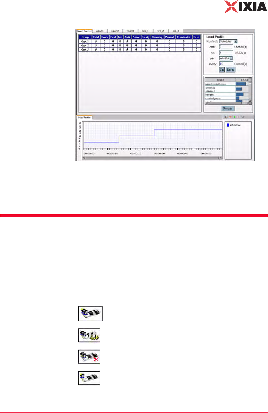
IxWLAN User Guide, Release 6.20 4-25
The Web-Based User Interface
vSTA Side Bar
Figure 4-36. Load Profile Setup and Graph
After a five-second delay, the web-based user interface instructs IxWLAN to run
four virtual stations. Every five seconds thereafter, the web-based user interface
instructs IxWLAN to run another four virtual stations until all virtual stations are
executed. The graph depicts this scheduling scheme.
vSTA Side Bar
In the web-based user interface, you can create scenarios that consist of one or
more groups of virtual stations. The group configuration defines a test sequence
that IxWLAN activates to exercise the System Under Test. Virtual stations can
be configured individually or by group. In internal mode, you can configure each
virtual station and/or group to generate traffic to the system being tested. You can
also configure virtual stations to operate in external mode where an external load
generator generates the traffic.
New Group: Defines a new group in a scenario.
Edit Group: Modifies the definition of a group.
Delete Group: Removes a group and all its virtual stations from a
scenario.
Add vSTA to Group: Defines a new virtual station in a scenario
group.
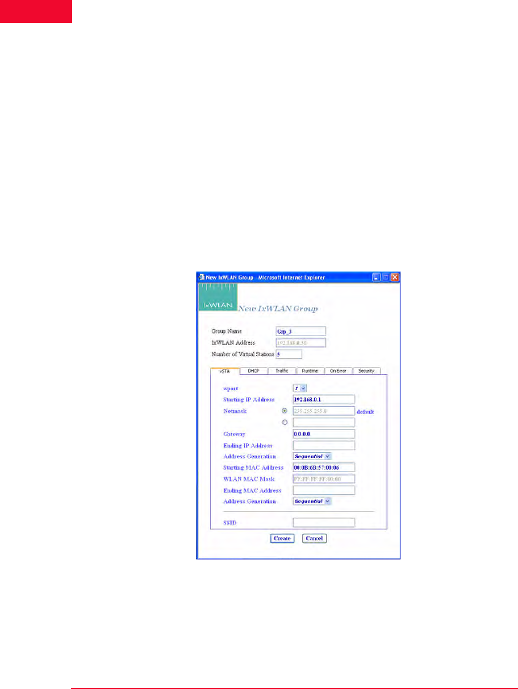
The Web-Based User Interface
vSTA Side Bar
4-26 IxWLAN User Guide, Release 6.20
4
vSTA->New Group The New Group dialog allows you to define new groups of virtual stations in a
scenario. It is a tabbed dialog with the following sections: vSTA, Traffic, Runt-
ime, On Error, and Security.
•The Create button allows you to create the group.
•The Cancel button allows you to exit the dialog.
vSTA->New Group->vSTA
The vSTA section of the New IxWLAN Group dialog defines the range of IP and
MAC addresses to be used by virtual stations, as shown in Figure 4-37 on page 4-
26.
The range of MAC addresses specified in this dialog must be within the range of
MAC addresses defined by the WLAN Base MAC Address and WLAN MAC
Mask in the IxWLAN configuration (see IxWLAN->Configure IxWLAN on page
4-44).
Figure 4-37. vSTA Section
Group Name: Use a group name that helps you identify the devices to be tested
(for example, Warehouse, Stock_Room, Ctrl_Tower, Shop_Floor, and so on.). It
can be up to 12 characters (a…z, 0…9, and underscore (_)).
IxWLAN Address: Shows the IP address of IxWLAN that runs this scenario/test.

IxWLAN User Guide, Release 6.20 4-27
The Web-Based User Interface
vSTA Side Bar
Number of Virtual Stations: Type the number of virtual stations to create in this
scenario group. The maximum number of vSTAs for the IxWLAN SED chassis
is 64, and 128 for the IxWLAN SED-MR+ chassis. The default value is 5. If you
specify zero virtual stations in this dialog, you must use the Add vSTA to Group
dialog to add one or more virtual stations to this group. The Add vSTA to Group
dialog uses the default parameters that you set in this group definition.
wport: Select the number of the wport (1, 2, or 3). Subsequently, the group is cre-
ated on the chosen wport.
Starting IP Address: If Sequential or Random is selected in the Address Gener-
ation field, type the starting IP address to use for virtual station IP address gener-
ation of newly-created virtual stations in this group. Successive virtual station IP
addresses are sequentially or randomly generated from this base address.
Netmask: Shows the network mask to be used by virtual stations in this group. It
cannot be set here. It is global for all virtual stations and an IxWLAN configura-
tion parameter.
Ending IP Address: If Random is selected in the Address Generation field, type
the ending IP address to be used by virtual stations in this group when generating
random addresses within a range.
Address Generation: Select Sequential, Random, or DHCP from the drop-down
list box. The Sequential or Random selections instruct IxWLAN to sequentially
or randomly assign IP addresses to newly-created virtual stations. The DHCP
mode allows virtual stations to have IP addresses dynamically acquired from a
DHCP server on the WLAN network rather than a fixed, configured IP address.
If DHCP is selected, IxWLAN initiates lease negotiation if association succeeds
for each individual virtual station.
Starting MAC Address: Type the starting MAC address to be used for virtual sta-
tion MAC address generation of newly-created virtual stations in this group. Suc-
cessive virtual station MAC addresses are sequentially or randomly generated
from this base address. The starting MAC address must be within the range of
MAC addresses defined by the WLAN Base MAC Address and WLAN MAC
Mask in IxWLAN configuration (see IxWLAN->Configure IxWLAN on page 4-
44).
WLAN MAC Mask: The WLAN MAC Mask is a display-only field. It is defined
in IxWLAN configuration (see IxWLAN->Configure IxWLAN on page 4-44). It
limits the range of MAC addresses that can be detected on the wireless LAN and
received by IxWLAN. For example, if the WLAN MAC is set to
00:0b:cd:59:23:44 and the mask is set to ff:ff:ff:ff:00:00, the only MAC
addresses that can be detected on the wireless LAN and received by IxWLAN are
00:0b:cd:59:00:00 - 00:0b:cd:59:ff:ff. All other MAC addresses are filtered
out.
NOTE: If you intend to configure all virtual stations for WPA or RSN
authentication, the maximum number of virtual stations is 59.
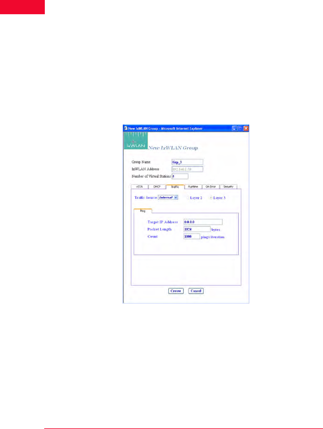
The Web-Based User Interface
vSTA Side Bar
4-28 IxWLAN User Guide, Release 6.20
4
Ending MAC Address: Type the ending MAC address to be used by virtual sta-
tions in this group.
SSID: Set the SSID to a string. The user can create a vSTA with a SSID. This is
an optional field.
vSTA->New Group->Traffic
The Traffic section of the New IxWLAN Group dialog defines the type of traffic
(Internal/Ping or External/Load Generator) to be used by the virtual station(s), as
shown in Figure 4-38.
Figure 4-38. vSTA Traffic
Traffic Source: Select Internal or External from the list box. In Internal mode,
traffic is generated internally by each vSTA using ICMP Echo (Ping) Request/
Reply packets. In External mode, packets coming into IxWLAN over 802.3 are
mapped to virtual stations by source IP or MAC address and forwarded via
802.11. Packets coming back via 802.11 are remapped to the originating MAC
address.
Layer 2/Layer 3: If External is selected in the Traffic Source field, select one of
these radio buttons to identify the external frames to be captured. If Layer 2 is
selected, frames are captured based on the source 802.3 MAC address. If Layer 3
is selected, frames are captured based on the source IP address. For vSTAs con-
figured at layer 3, IP and ARP packets generated from this host that contain the
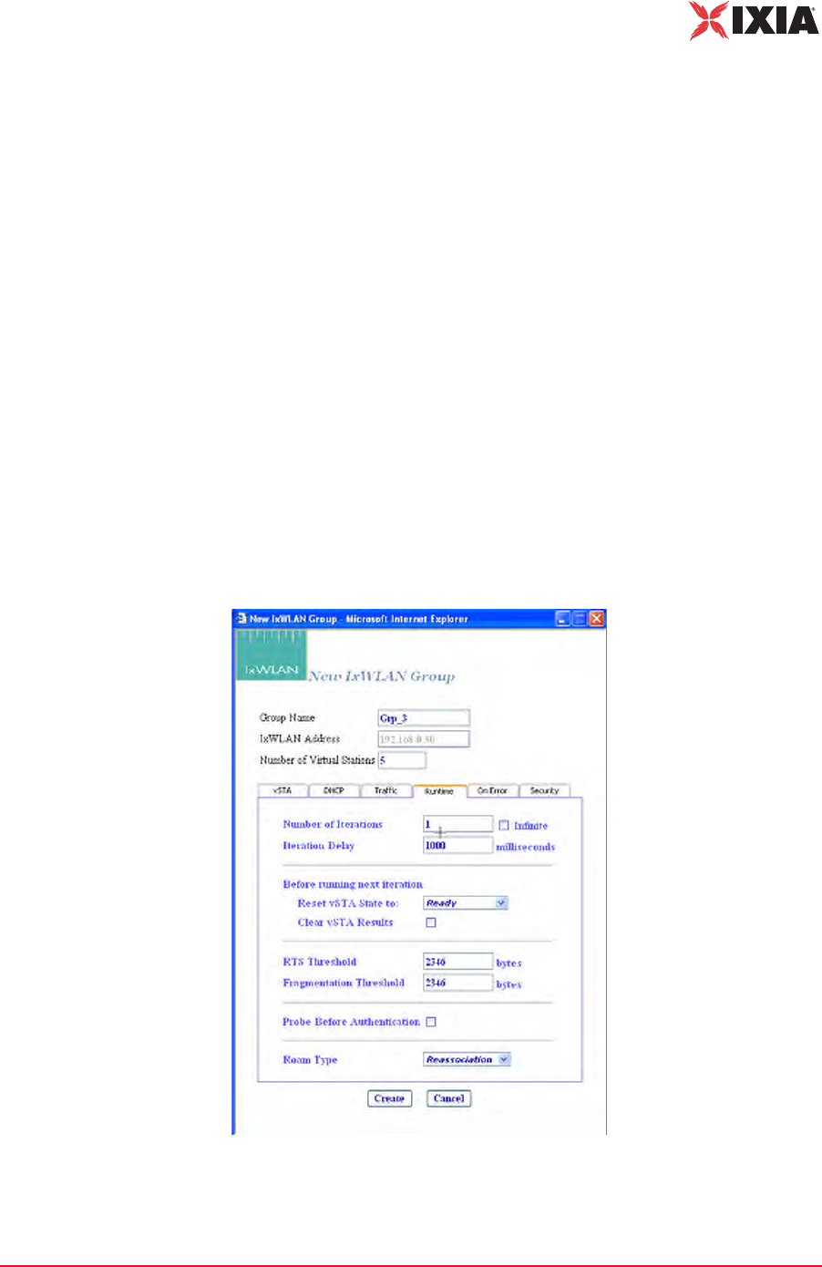
IxWLAN User Guide, Release 6.20 4-29
The Web-Based User Interface
vSTA Side Bar
virtual station's IP address as a source are translated at the MAC layer to appear
as if sourced from the virtual station's MAC address.
Target IP Address: Type the target IP address where ICMP Echo (Ping) Requests
should be sent. The default IP address (0.0.0.0) shown in this example dialog
must be replaced by a valid IP address (for example, 192.168.0.19).
Packet Length: Specify the size of the ping data buffer (64…1024). The default is
1024.
Count: Specify the total number of pings to be sent: 0…10000 (0=forever).
vSTA->New Group->Runtime
The Runtime section of the New IxWLAN Group dialog allows you to run a vir-
tual station’s test multiple times. This is applicable only to internal traffic genera-
tion. After each iteration of a test, the state of the virtual station can be set to a
base state. A user-defined delay between successive iterations is defined in mil-
liseconds (ms). Optionally, any results collected for the virtual station can be
cleared at the start of each iteration.
Figure 4-39 shows the Runtime section of the New IxWLAN Group dialog.
Figure 4-39. vSTA Runtime

The Web-Based User Interface
vSTA Side Bar
4-30 IxWLAN User Guide, Release 6.20
4
Number of Iterations: Type the number of times (1…10000) to repeat the virtual
station’s task (Ping) or click the Infinite checkbox to continuously iterate indefi-
nitely.
Iteration Delay: Type the delay (in ms) to be introduced between iterations of the
test. It can be set to a value in the 0 to 300000 ms (5 min) range.
Before Running Next Iteration->Reset vSTA State to: Select a state from the list
box. Each virtual station in this group resets to the selected state (started, authen-
ticated, or associated) at the end of each iteration.
Before Running Next Iteration->Clear vSTA Results: Select this checkbox to
clear test results before successive iterations of the test.
RTS Threshold: Type a value in the 1 to 2346 range to define the RTS threshold
for the virtual station(s) in this group. Any frame to be transmitted by a virtual
station that exceeds the RTS threshold needs a successful RTS/CTS frame
exchange before the frame is transmitted. The minimum value (1) effectively
needs RTS/CTS for all transmit frames. The maximum value (2346) is the maxi-
mum 802.11 frame size and effectively disables RTS.
Fragmentation Threshold: Type a value in the 256 to 2346 range to define the
fragmentation threshold for the virtual station(s) in this group. The fragmentation
threshold limits the number of bytes in any 802.11 frame transmitted by the vir-
tual station(s). If this field is set to 2346 (that is, the maximum 802.11 frame
size), fragmentation is effectively disabled.
Probe before Authentication: An option to select whether to issue a Probe
Request in the course of association lifecycle, before the 802.11 authentication.
Roam Type: Select Reassociation or Disassociation. Indicates the type of frame
exchange to be used for virtual station(s) in this group during a Roam operation:
Reassociation (a Reassociation Request is sent to the target AP) or Disassociation
(a Disassociation frame is first sent to the origin AP and an Association Request
frame is sent to the target AP).
vSTA->New Group->On Error
The On Error section of the New IxWLAN Group dialog defines whether virtual
stations should reconnect to the System Under Test during a test if the system de-
authenticates or disassociates a virtual station, as shown in Figure 4-40 on page
4-31.
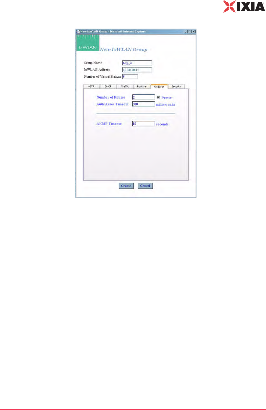
IxWLAN User Guide, Release 6.20 4-31
The Web-Based User Interface
vSTA Side Bar
Figure 4-40. vSTA Error
Number of Retries: Specifies the number of times IxWLAN should issue authen-
tication and association requests before failing the operation. It can be a value in
the 0 to 10 range.
Persist: Click the checkbox to enable or disable persistence. When enabled, vir-
tual stations in this group remain persistent (connected) if the System Under Test
deauthenticates or disassociates. If IxWLAN loses connection to a System Under
Test, persistence allows it to recover and continue the test at the point where it
was interrupted. For example, if a virtual station is in a run or associated state and
an 802.11 management frame (deauth or disassoc) is sent by the System Under
Test and received by IxWLAN, the virtual station tries to return to the state it was
in, before the management frame was received. If the virtual station was running
a ping test, the ping test continues. If it was in an associated state, the virtual sta-
tion reissues the associate request.
Auth/Assoc Timeout: Specifies the timeout value (in ms) for authentication and
association requests. It can be set to a value in the 250 to 60000 ms (1 min) range.
AKMP Timeout: Sets a wait state timer (0…3600 s) for the virtual stations in the
group. In situations where the System Under Test does not start or respond dur-
ing a 4-way handshake, the affected virtual station may stall in a wait state. The
timer can be used to recover the virtual station into an operable state. If the vir-
tual station remains in a wait state until this timer expires, it is 802.11 de-authen-
ticated and returned to the beginning state. The default value (zero) disables the
timer (that is, wait forever).

The Web-Based User Interface
vSTA Side Bar
4-32 IxWLAN User Guide, Release 6.20
4
vSTA->New Group->Security
This section of the New Group dialog defines whether the virtual station uses
security, the type of authentication to be used for authenticating with the System
Under Test, and the associated cipher to use.
Encryption: Select On or Off from the drop-down list box to enable/disable
encryption.
Authentication: Select an authentication type: Open System, Shared Key, RSN,
RSN-PSK, WPA, or WPA-PSK. If you select RSN or WPA, define user creden-
tial parameters in the EAP tab. If you select RSN-PSK or WPA-PSK, define a
pre-shared key or passphrase in the PSK tab.
Cipher: For Open System or Shared Key Authentication, WEP is the only valid
selection. For RSN, RSN-PSK, WPA, and WPA-PSK Authentication, select
TKIP or AES-CCM (that is, CCMP cipher mode).
Fast Radius: The default value of this attribute is Disabled. When a vSTA is
configured for fast RADIUS reconnection and the vSTA has cached the TLS ses-
sion information, it tries fast resumption in subsequent 802.1X authentication
exchanges by using the session_id and master_key from that cached TLS session.
PMKSA Cache: Enables the use of the cached PMKSA information when
(re)associating. The default value is Enabled. Each entry in the PMKSA cache
contains the BSSID of the corresponding AP, a PMKID, and the Pairwise Master
Key (PMK). A PMKSA can be obtained by 802.1X authentication or by pre-
authentication.
vSTA->New Group->Security WEP Tab
For Open System or Shared Key Authentication and WEP Cipher mode, this sec-
tion of the New Group dialog allows you to define up to four shared keys, as
shown in Figure 4-41 on page 4-33.
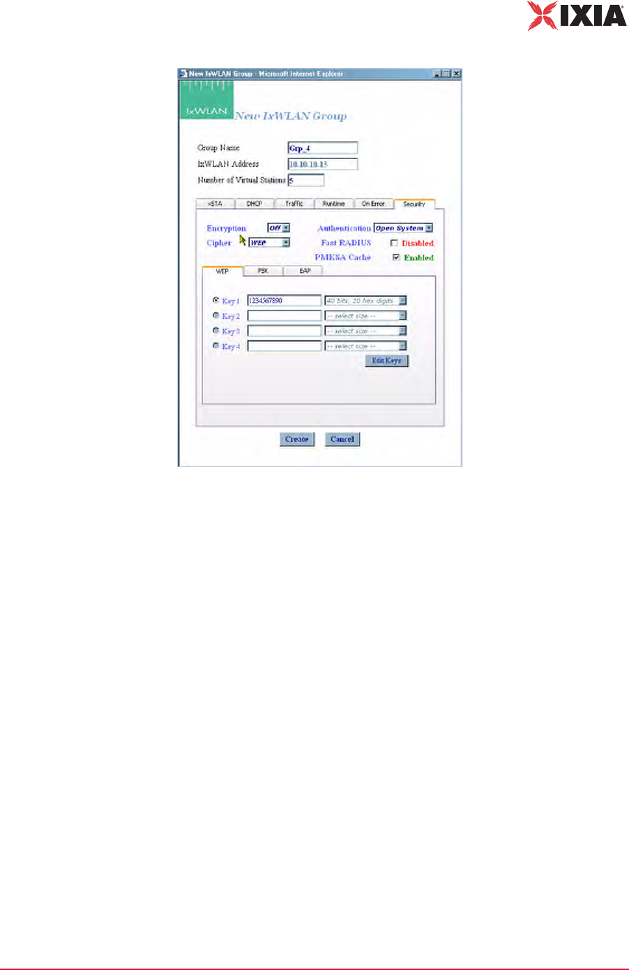
IxWLAN User Guide, Release 6.20 4-33
The Web-Based User Interface
vSTA Side Bar
Figure 4-41. Security Keys
Key 1…4: This section of the dialog shows the shared keys that were defined in
the Security Configuration dialog. For further information, please refer to
Configuration->Security on page 4-71. Select the shared key to be used. These
keys are used for encryption by virtual stations in this group with the System
Under Test.
Edit Keys: The Edit Keys button allows you to change the keys in this dialog.
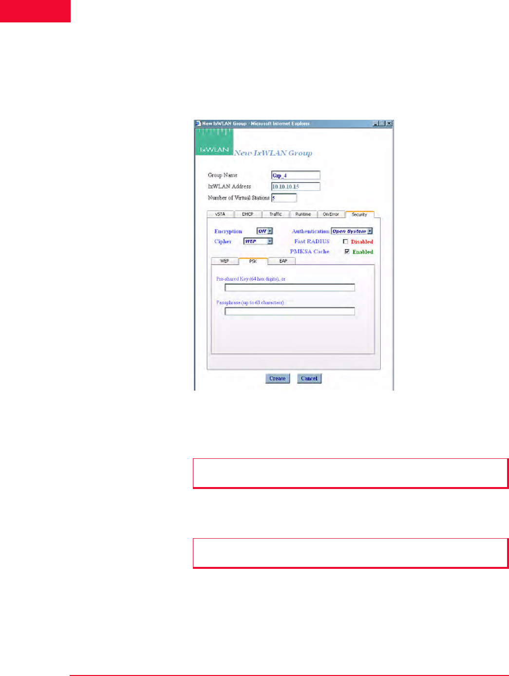
The Web-Based User Interface
vSTA Side Bar
4-34 IxWLAN User Guide, Release 6.20
4
vSTA->New Group->Security PSK Tab
If you have selected WPA-PSK or RSN-PSK in the Authentication field, this
section of the dialog defines a Pre-Shared Key or passphrase, as shown in Figure
4-42.
Figure 4-42. Security PSK Tab
Pre-Shared Key (64 hex digits): Defines a Pre-Shared Key (64 ASCII-hex char-
acters) for all virtual stations in this group.
Passphrase (up to 63 characters): Defines a passphrase of up to 63 ASCII charac-
ters.
NOTE: When using a Pre-Shared Key, it is not necessary to specify the
passphrase.
NOTE: When a passphrase is defined, it is not necessary to specify the Pre-
Shared Key. The passphrase is used to generate the Pre-Shared Key.
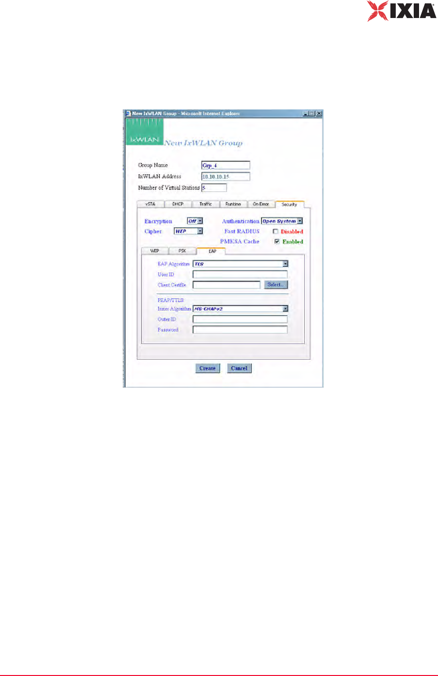
IxWLAN User Guide, Release 6.20 4-35
The Web-Based User Interface
vSTA Side Bar
vSTA->New Group->Security EAP Tab
If you have selected RSN or WPA in the Authentication field, this dialog allows
you to define user credential parameters, as shown in Figure 4-43.
Figure 4-43. Security EAP Tab
EAP Algorithm: Select TLS, TTLS, or PEAP from the drop-down list box. If
you select PEAP or TTLS, define Inner Algorithm, Outer ID, and Password in
the PEAP/TTLS section.
User ID: Defines the user ID for virtual stations in this group. It can be up to 64
characters in the range A…Z, a…z, 0…9, or other legal characters: period (.),
dash (-), at-sign (@).
Client Certfile: Defines the certificate file for virtual stations in this group.
Select…: Click the Select... button to open the Available Certificates dialog and
select a certificate file. See Available Certificates on page 4-36.
PEAP/TTLS Parameters: When PEAP or TTLS is selected in the EAP Algo-
rithm list box, use this section of the dialog to define PEAP/TTLS parameters.
Inner Algorithm: Select the inner algorithm to use in Phase 2 authentication. MS-
CHAPv2 is normally used for TTLS. EAP-MS-CHAPv2 is normally used for
PEAP.
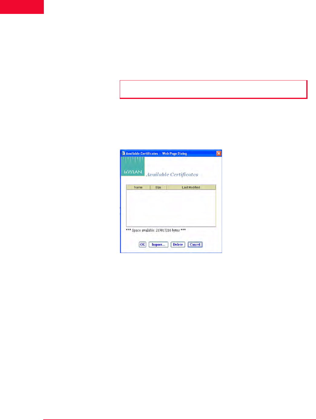
The Web-Based User Interface
vSTA Side Bar
4-36 IxWLAN User Guide, Release 6.20
4
Outer ID: Type an outer identity to use in Phase 1 authentication. It can be up to
64 characters in the range A…Z, a…z, 0…9, or other legal characters: period (.),
dash (-), at-sign (@).
Password: Type a password to use in Phase 2 authentication. It can be up to 64
characters.
Available Certificates
The Select button in the New Group/Security EAP tab opens the Available Cer-
tificates dialog, as shown in Figure 4-44.
Figure 4-44. Available Certificate Dialog
The Space available indicates the total available space in the IxWLAN flash file
system. This number changes when certificate files are added or deleted.
•The OK button (or double-clicking a file name in the list) allows you to set
the Client Certfile field to the currently highlighted certificate file name.
•The Delete button allows you to delete the currently highlighted certificate
file. A confirmation dialog asks you to confirm this selection. An error dialog
opens if the certificate file is in use by any vSTA, otherwise the certificate file
is deleted.
•The Cancel button allows you to exit the dialog.
•The Import… button allows you to open the Import Certfile dialog.
Certfile: Type the complete path and name of a certificate file or click the
Browse… button to open the File Browse dialog as shown in Figure 4-45 on
page 4-37 and then select from the files stored on the command PC.
NOTE: Inner Algorithm, Outer ID, and Password are only used for TTLS and
PEAP. They are ignored for TLS.
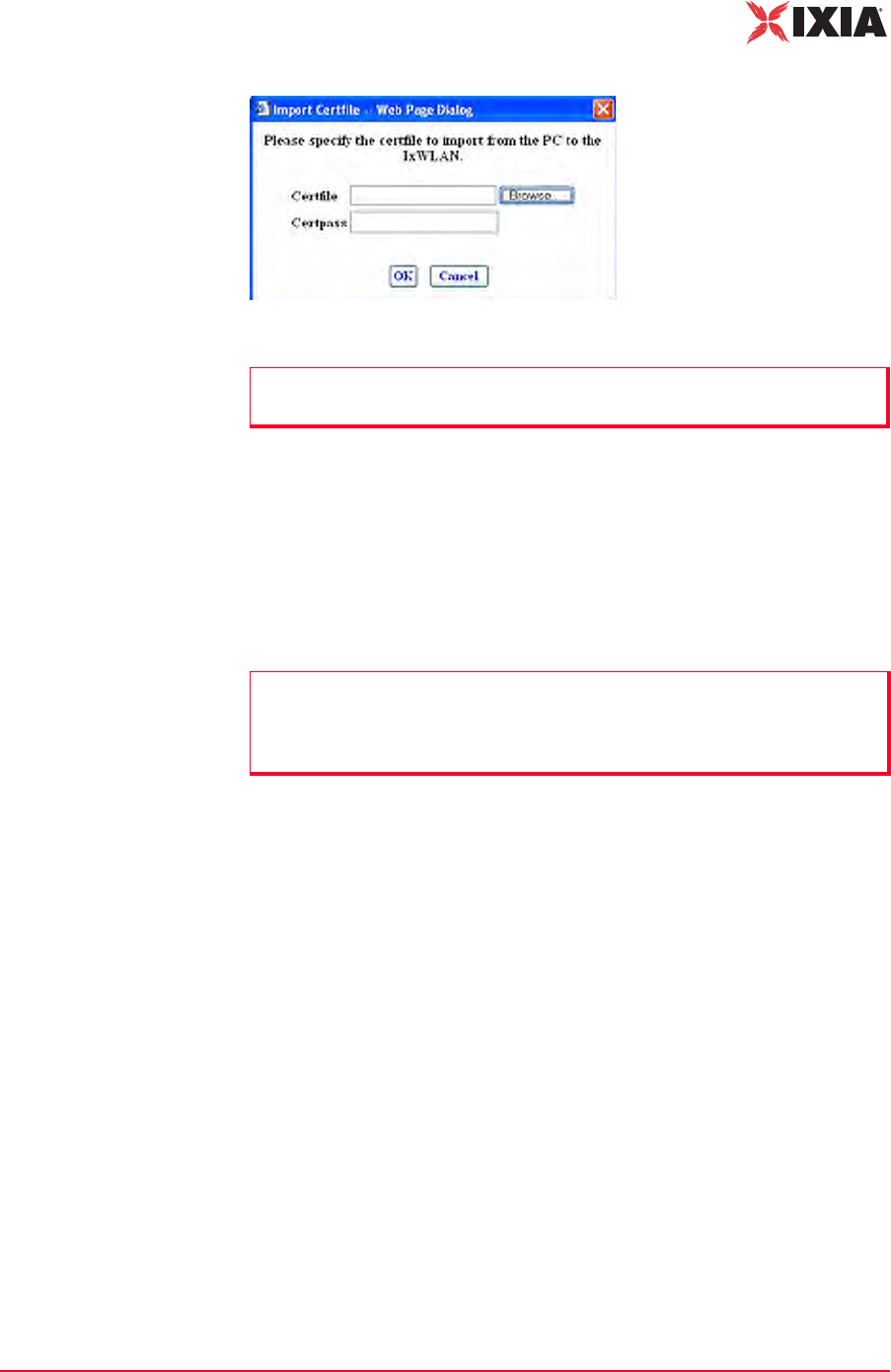
IxWLAN User Guide, Release 6.20 4-37
The Web-Based User Interface
vSTA Side Bar
Figure 4-45. Import Certfile Dialog
Certpass: After a file name is typed or selected, enter the password needed for
the certificate file.
•The OK button allows you to transfer the specified file to IxWLAN with the
same file name and extension. The newly-added certificate file is then listed
as one of the available certificates.
•The Cancel button allows you to close this dialog without selecting a certifi-
cate file.
NOTE: Certificate files must be in PKCS#12 format, which is usually indicated
by a .p12 or a .pfx file extension.
NOTE: You can view each vSTA’s User ID and Certificate file by editing the
vSTA or by including the WPA User ID and WPA Certfile attributes in the table
view. See Group Tab Columns under Group Control Grid in Using the Main
Page on page 4-14.
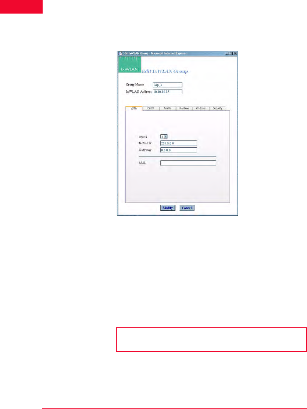
The Web-Based User Interface
vSTA Side Bar
4-38 IxWLAN User Guide, Release 6.20
4
vSTA->Edit Group The Edit IxWLAN Group dialog opens, as shown in Figure 4-46, when the Edit
Group button is selected in the vSTA side bar.
Figure 4-46. Edit IxWLAN Group Dialog
Figure 4-46 is the same as the vSTA->New Group dialog, except for the vSTA
tab, which is different. Thus, in the vSTA tab, after the virtual stations have been
created, the wport, Netmask, and Gateway group attributes cannot be changed. In
addition, the Number of virtual stations field is not present in the Edit IxWLAN
Group dialog. To add a virtual station to the group, refer to vSTA->Add New
vSTA to Group on page 4-39. For more information about the description of the
fields in this dialog, please refer to vSTA->New Group on page 4-26.
•The Modify button allows you to modify all virtual stations with the new set-
tings.
•The Cancel button allows you to close this dialog without modifying any vir-
tual stations.
NOTE: The group’s wport attribute can be edited only if the system is in the
dynamic mode. In the static mode, the wport selection is disabled, appearing
dimmed.
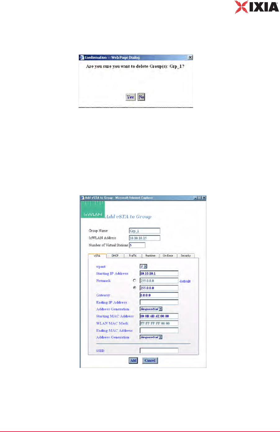
IxWLAN User Guide, Release 6.20 4-39
The Web-Based User Interface
vSTA Side Bar
vSTA->Delete
Group
When the Delete Group button is clicked from the vSTA side bar, a confirma-
tion dialog prompts you to confirm this selection, as shown in Figure 4-47.
Figure 4-47. Confirmation Dialog
•Click Yes to remove the group and all virtual stations that it contains from the
system.
•Click No to close this dialog without removing the group.
vSTA->Add New
vSTA to Group
Figure 4-48 opens when the Add New vSTA to Group button is selected in the
vSTA side bar.
Figure 4-48. Add New vSTA to Group
This dialog is used to add new virtual stations to an existing group. All fields in
this dialog default to the values that were first entered when the group was cre-
ated. Any changes to this dialog also update these group default values. See
vSTA->New Group on page 4-26 for a description of the fields in this dialog.
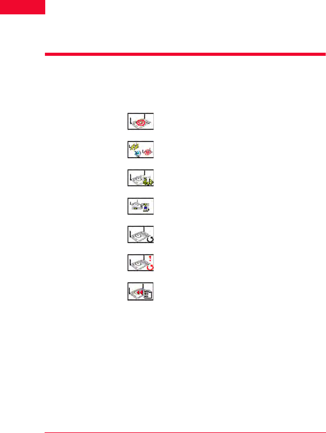
The Web-Based User Interface
IxWLAN Side Bar
4-40 IxWLAN User Guide, Release 6.20
4
•The Add button allows you to add the virtual station.
•The Cancel button allows you to close this dialog.
IxWLAN Side Bar
The buttons in this side bar are used to configure and manage IxWLAN and to
select and join with a System Under Test.
Select SUT: Opens the Select System Under Test dialog.
Join SUT(s): Joins with the System Under Test.
Configure IxWLAN: Configures IxWLAN.
Reconnect IxWLAN: Reconnects to IxWLAN. This is used after a
reboot of IxWLAN.
Reset IxWLAN: Resets all statistics counters to zero and all
virtual stations to a configured state.
Reboot IxWLAN: Reboots IxWLAN.
Update IxWLAN: Updates IxWLAN with a new firmware image file
or feature key.
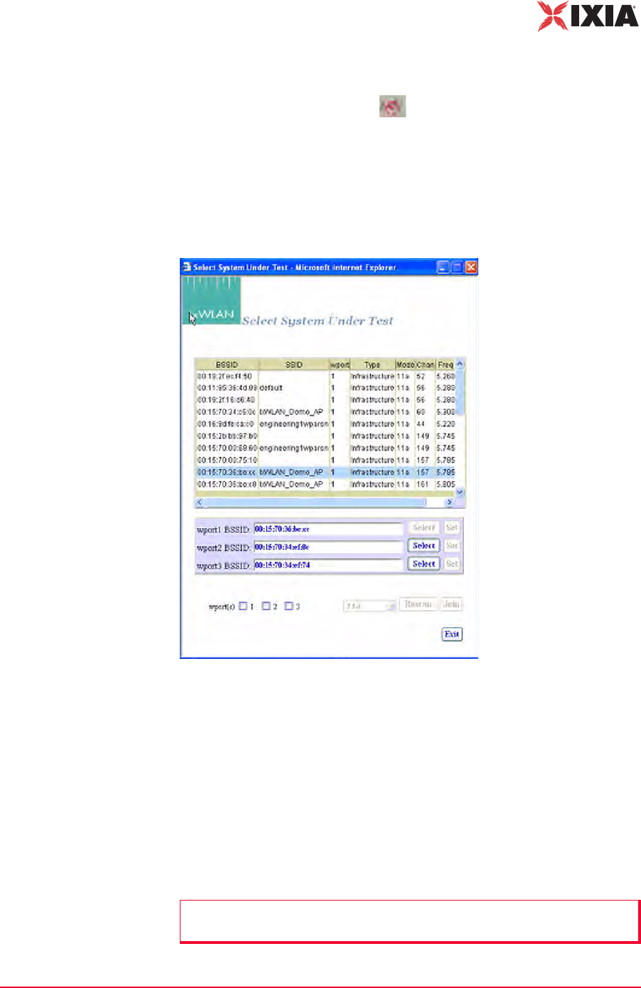
IxWLAN User Guide, Release 6.20 4-41
The Web-Based User Interface
IxWLAN Side Bar
IxWLAN->Select
SUT
You can access the Select System Under Test dialog (Figure 4-49) in two ways:
1. Click one of the wport-specific Select SUT buttons in the System Under
Test status tool bar at the top of the main window. In this case, when the
Select System Under Test dialog opens, only the wport checkbox correspond-
ing to the checked button is selected.
2. Click the Select SUT(s) button in the IxWLAN side bar. In this case, when
the Select System Under Test dialog opens, none of the three wport check-
boxes are selected.
Figure 4-49. Select System Under Test
•Select one of the wport BSSID checkboxes (for example, wport1).
•Click a BSSID in the list box.
•Click the Select button next to the wport1 BSSID box. The selection is copied
into the wport1 BSSID box.
•Click the Set button corresponding to the wport1 BSSID box.
•Select the wport1 checkbox.
•Click the Join button to join wport1 with the selected System Under Test.
NOTE: Clicking Join implicitly performs a Set action first (if not done explicitly
by clicking the Set button).
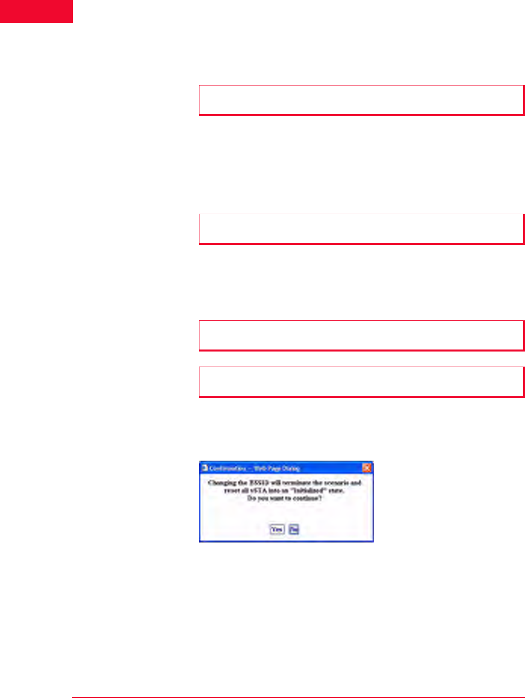
The Web-Based User Interface
IxWLAN Side Bar
4-42 IxWLAN User Guide, Release 6.20
4
•Click the Rescan button to update the list of BSSIDs. The merged list of new
wport1 BSSIDs and old BSSIDs for wport2 and wport3 displays.
•The Select button adjacent to a wport adds the respective BSSID in the list
box to the edit box left of it.
•The Set button sets the wport adjacent to it to the BSSID left of it.
•Click the Exit button to close this dialog without making any further changes.
To change the wireless mode, select 11a, 11b, 11g, or All Modes (that is, all
valid wireless modes) from the drop-down list adjacent to the Rescan button.
This field is used to select a wireless mode for optional successive scanning. It
defaults to the current wireless mode configured for the unit.
If a scenario with virtual stations already exists and you have previously joined
with a system under test, the dialog shown in Figure 4-50 opens when you select
a different BSSID in the Select System Under Test dialog.
Figure 4-50. Selecting Different BSSID in the Select SUT Dialog
•Click Yes to continue and join with a different System Under Test.
•Click No to return to the Select System Under Test dialog.
IxWLAN->Join
SUT(s)
When the Join SUT button is selected in the IxWLAN side bar, a confirmation
dialog opens.
NOTE: If no wport checkbox is selected, the Rescan and Join buttons are
dimmed, as shown in Figure 4-49 on page 4-41.
NOTE: The Exit button does not undo any set, join, and rescan operations that
have already taken place.
NOTE: The wireless mode for the unit is set in the IxWLAN Radio tab of the
Configure IxWLAN dialog.
NOTE: For the IxWLAN SED chassis, the Select System Under Test dialog
looks the same, except for wports 2 and 3, which are dimmed.
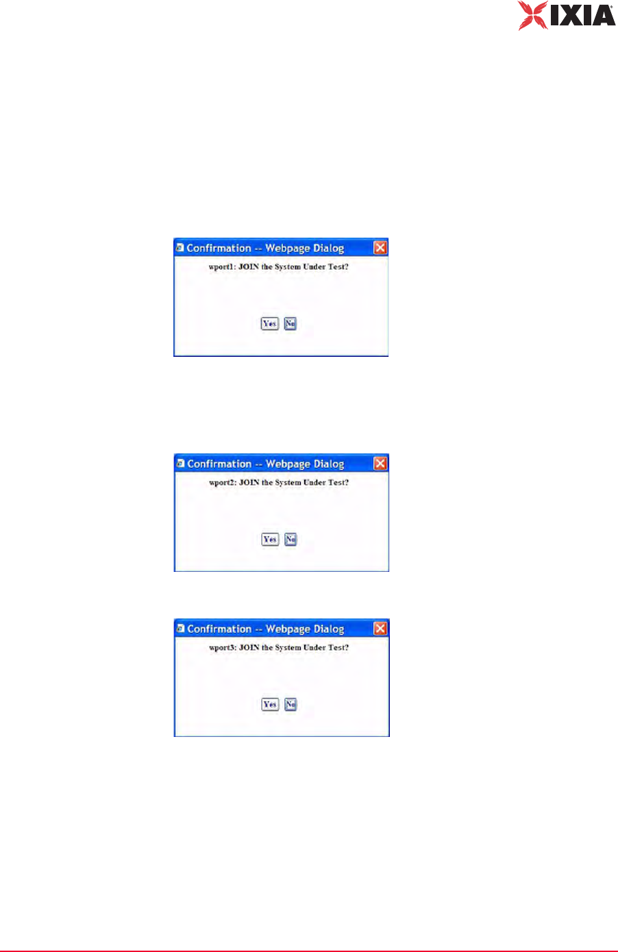
IxWLAN User Guide, Release 6.20 4-43
The Web-Based User Interface
IxWLAN Side Bar
If the web-based user interface is running on an IxWLAN SED chassis, clicking
this icon results in an attempt to join wport1, provided it is not already joined.
When on an IxWLAN SED-MR+ chassis, clicking this button results in an
attempt to join a combination of wport1, wport2, and wport3 (whichever is not
already joined). The joins are attempted on all (not joined) wports, regardless of
whether their corresponding checkbox in the Select System Under Test dialog is
selected or not. For example, if wport1 is not joined, the Join SUT dialog shown
in Figure 4-51 opens.
Figure 4-51. Join SUT wport1 Confirmation Dialog
Figure 4-52 and Figure 4-53 open if wport2 and wport3 respectively are not
joined.
Figure 4-52. Join SUT wport2 Confirmation Dialog
Figure 4-53. Join SUT wport3 Confirmation Dialog
•Click Yes to join with the System Under Test.
•Click No to cancel this operation.
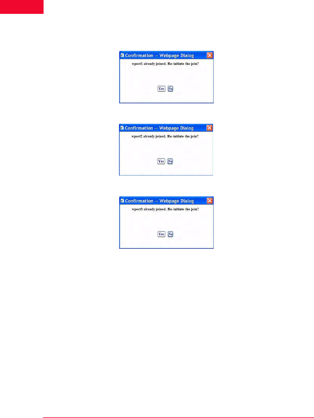
The Web-Based User Interface
IxWLAN Side Bar
4-44 IxWLAN User Guide, Release 6.20
4
For each wport that is already joined with a SUT, either Figure 4-54, Figure 4-55,
or Figure 4-56 opens.
Figure 4-54. Join SUT wport1 Re-initiation Confirmation Dialog
Figure 4-55. Join SUT wport2 Re-initiation Confirmation Dialog
Figure 4-56. Join SUT wport3 Re-initiation Confirmation Dialog
IxWLAN->Configure
IxWLAN
The Configure IxWLAN dialog is a tabbed dialog that defines the interaction
with the web-based user interface and IxWLAN operational parameters. The fol-
lowing fields appear in all sections of the Configure IxWLAN dialog:
IxWLAN Id: It is set by the system and cannot be changed.
IxWLAN Address: Shows IxWLAN's IP address.
•Click OK to save the configuration.
•Click Cancel to close the dialog.
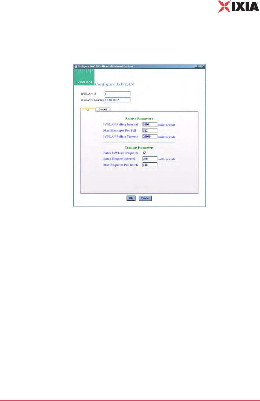
IxWLAN User Guide, Release 6.20 4-45
The Web-Based User Interface
IxWLAN Side Bar
IxWLAN->Configure IxWLAN->UI
The Configure IxWLAN button in the IxWLAN side bar opens the Configure
IxWLAN dialog, as shown in Figure 4-57.
Figure 4-57. Configure IxWLAN Dialog
Receive Parameters
IxWLAN Polling Interval: Defines the interval (in ms) during which the Com-
mand PC polls IxWLAN for command and control messages from the virtual sta-
tions. It can be set to a value in the 250…60000 ms (1 min) range. If this time
expires without an expected response from IxWLAN, the web-based user inter-
face displays Busy next to IxWLAN icon in the tool bar. The Busy message indi-
cates that IxWLAN is not responding to the user interface. Under normal
conditions, the Busy message may appear periodically for short periods of time.
If the Busy message appears frequently, you may want to increase the value
assigned to the IxWLAN Polling Interval. Also see IxWLAN Busy or Not
Responding on page 8-5.
Max Messages Per Poll: Specify the maximum number of messages to receive
in each poll: 1…128.
IxWLAN Polling Timeout: Defines the time (in ms) that the Command PC
waits for a response from IxWLAN. It can be set to a value in the 500…120000
ms (2 min) range. The recommended value is twice the IxWLAN Polling Inter-
val value. If this time expires without an expected response from IxWLAN, the
web-based user interface opens a dialog indicating that IxWLAN is not respond-
ing. When you dismiss the dialog, the status of the IxWLAN/System Under Test
connection in the tool bar shows Offline. If this dialog and Offline status appears

The Web-Based User Interface
IxWLAN Side Bar
4-46 IxWLAN User Guide, Release 6.20
4
frequently, a larger value should be assigned to the IxWLAN Polling Timeout.
Also see IxWLAN Busy or Not Responding on page 8-5.
Transmit Parameters
Batch IxWLAN Requests: The checkbox enables/disables batching of request
messages to be sent to IxWLAN. When virtual stations are running in an iterative
fashion or you issue commands to many virtual stations, this produces a large
number of requests to the web server on IxWLAN. Request batching maintains a
number of these requests over a period of time (defined by the Batch Request
Interval) and then issues one large request with all pending instructions.
Batch Request Interval: If Batch IxWLAN Requests is checked/enabled, spec-
ify the interval at which the web-based user interface l collects (batches) requests
and sends them to IxWLAN. It can be set to a value in the 250…60000 ms (1
min) range.
Max Requests Per Batch: Specifies the maximum number of requests that
should be batched before they are sent to the virtual stations. When this number
of requests have been batched, they are sent to IxWLAN even if the Batch
Request Interval has not expired.
IxWLAN->Configure IxWLAN->IxWLAN/Basic
This section of the Configure IxWLAN dialog defines the basic configuration of
IxWLAN, as shown in Figure 4-58 on page 4-47.
NOTE: Also see the Monitor Update Interval and Monitor Update Timeout in
Monitors->Config Monitors on page 4-62 for the interval and update timeout val-
ues that are used by the command PC to collect statistics.
NOTE: If you are currently running or intend to run a Load Profile, batching
IxWLAN requests may affect the timing of the Load Profile if the Batch Request
Interval is greater than the timing specified in the Load Profile.
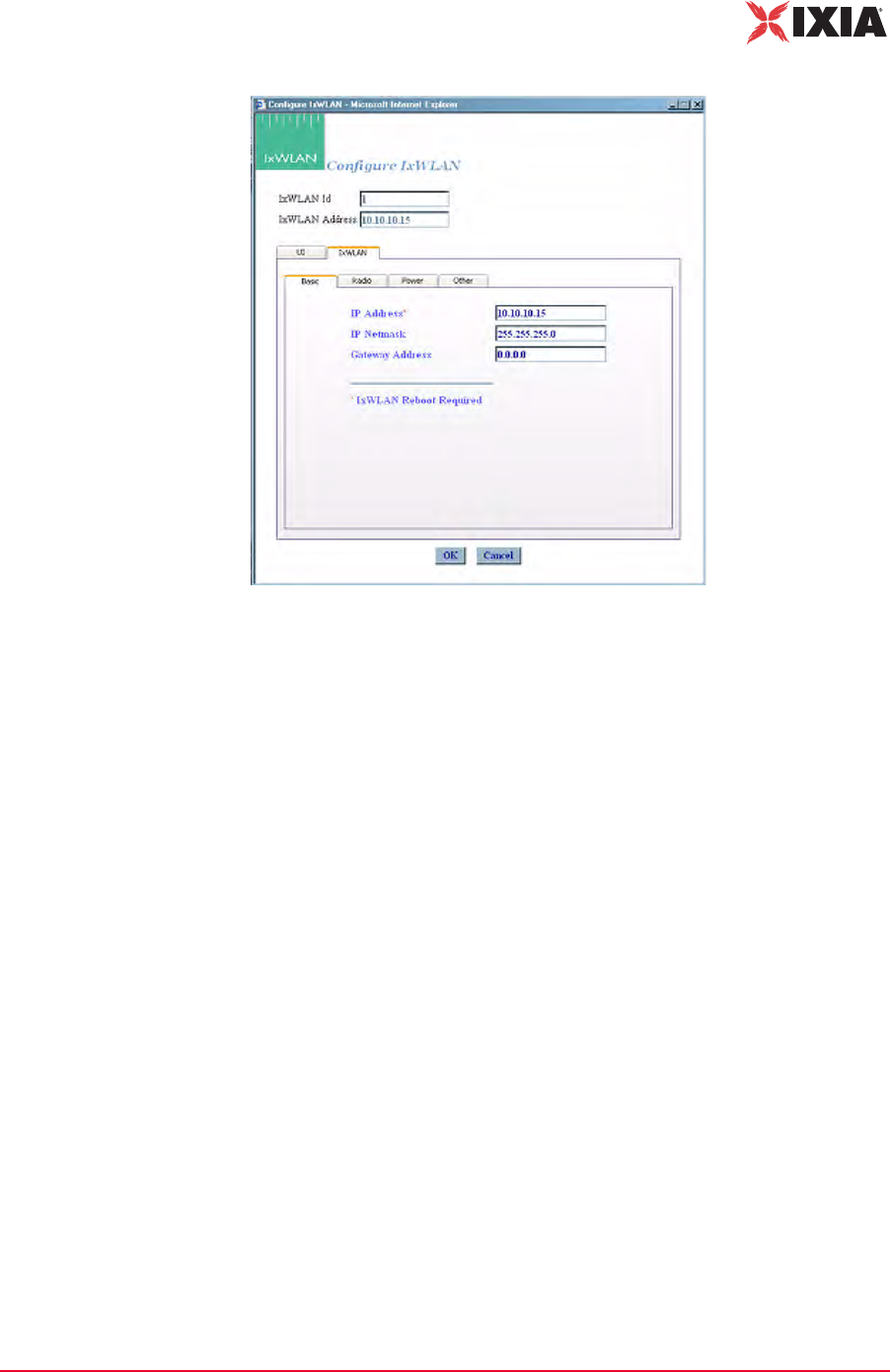
IxWLAN User Guide, Release 6.20 4-47
The Web-Based User Interface
IxWLAN Side Bar
Figure 4-58. Basic Configuration of IxWLAN
IP Address: Type IxWLAN's new IP address. Use an IP address that is compati-
ble with the network addressing scheme at your facility. The default IP address is
192.168.0.50. If you change this field, you must select the Reboot option from
the IxWLAN side bar, exit the web-based user interface, and reconnect to IxW-
LAN using the new IP address.
IP Netmask: Type IxWLAN's network mask. The network mask of IxWLAN
must match the IP subnet addressing scheme for internal mode testing (it is not
used for external mode). For example, if IxWLAN's IP address is 10.1.40.18 and
the system being tested is 10.1.35.17, then the subnet mask is 16 bits or
255.255.0.0.
Gateway Address: Type IxWLAN's default gateway IP address. Use an IP
address that is compatible with the network addressing scheme at your facility.
The default gateway address is 0.0.0.0.
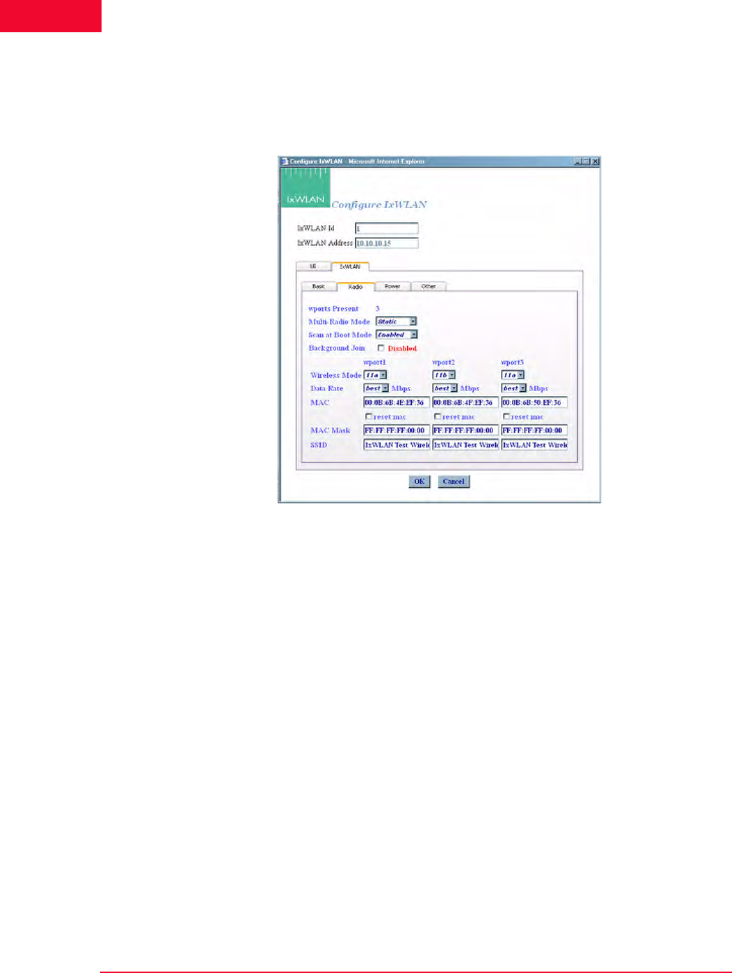
The Web-Based User Interface
IxWLAN Side Bar
4-48 IxWLAN User Guide, Release 6.20
4
IxWLAN->Configure IxWLAN->IxWLAN/Radio
This section of the IxWLAN->Configure IxWLAN dialog defines the wireless
mode and data rate of IxWLAN, as shown in Figure 4-59.
Figure 4-59. IxWLAN Radio
Wireless Mode: Select a wireless mode (11a, 11b, or 11g) from the list box. The
items that are available in this list box are different depending on the feature set
that you ordered from Ixia. The wireless mode also affects the types of devices
that IxWLAN can discover during a scan operation. See General Usage Notes on
page 1-12.
Data Rate: Select a data rate from the list box. The rates that are available in this
list box are different depending on the Wireless Mode selection.
MAC: The Wireless LAN MAC address defaults to a specific address (typically
in the 00:0b:cd:xx:xx:xx range). It is a globally unique MAC address that is pro-
grammed on the IxWLAN SED/SED-MR+ chassis. The address can be changed
to any non-broadcast or non-multicast valid MAC address. If you use multiple
IxWLANs at your facility, each must have a WLAN MAC whose prefix is
unique. For example, on the first IxWLAN, use WLAN MAC Address
04:0d:e0:62:23:57 and on the second IxWLAN, use WLAN MAC Address
06:0f:14:62:32:a0.
reset mac: Select this checkbox to reset the WLAN MAC Base Address to its
factory default setting.
MAC Mask: This address is used in conjunction with the WLAN Base MAC
Address for configuration of virtual stations for a specific wport. If for example,

IxWLAN User Guide, Release 6.20 4-49
The Web-Based User Interface
IxWLAN Side Bar
the WLAN MAC is set to 00:0b:cd:59:23:44 and the mask is set to
ff:ff:ff:ff:00:00, the only MAC addresses that can be detected on WLAN and
received by IxWLAN are 00:0b:cd:59:00:00 - 00:0b:cd:59:ff:ff. All other
MAC addresses are filtered out. The mask limits the range of MAC addresses
that are assigned to virtual stations on a wport. The mask that is specified here
displays in the WLAN MAC Mask field when the vSTA tab is selected in the New
IxWLAN Group dialog (See vSTA->New Group->vSTA on page 4-26).
SSID: Defines a Service Set ID. The SSID is a text string of up to 32 characters.
Control characters are not allowed. An SSID is used in Association Requests and
in deriving the Pre-Shared Key from the Passphrase, when appropriate. Nor-
mally, the SSID supplied in the Beacon from the SUT is used. When the SUT is
configured with a hidden SSID (not published in its Beacon), IxWLAN's SSID
attribute is used as a default.
Multi-Radio Mode: Allows you to select the multi radio mode to be either
dynamic or static.
Scan at Boot Mode: There are three options for this attribute: Enabled, Disabled,
and All Modes. If enabled, a scan of all channels of the IxWLAN Wireless Mode
(which can be set by the Wireless Mode list box shown in Figure 4-59 on page 4-
48) takes place at boot. If disabled, no scan takes place at boot. If set to All
Modes, a scan of all channels in all valid wireless modes (that is, 802.11a/b/g)
takes place at boot. The BSS list resulting from the all-mode scan shows BSSs
detected across all scanned channels.
Background Join: When Background Join is enabled, the unit allows manage-
ment frames to be sent before formally joining with the SUT and it automatically
conducts the Join in the background while this is happening. When disabled, the
system must be explicitly joined with the SUT before any management frames
(and thus data frames) can be sent.
IxWLAN->Configure IxWLAN->IxWLAN/Power
This section of the Configure IxWLAN dialog defines the power configuration of
IxWLAN, as shown in Figure 4-60 on page 4-50.
NOTE: The MAC and MAC Mask are per-wport attributes.
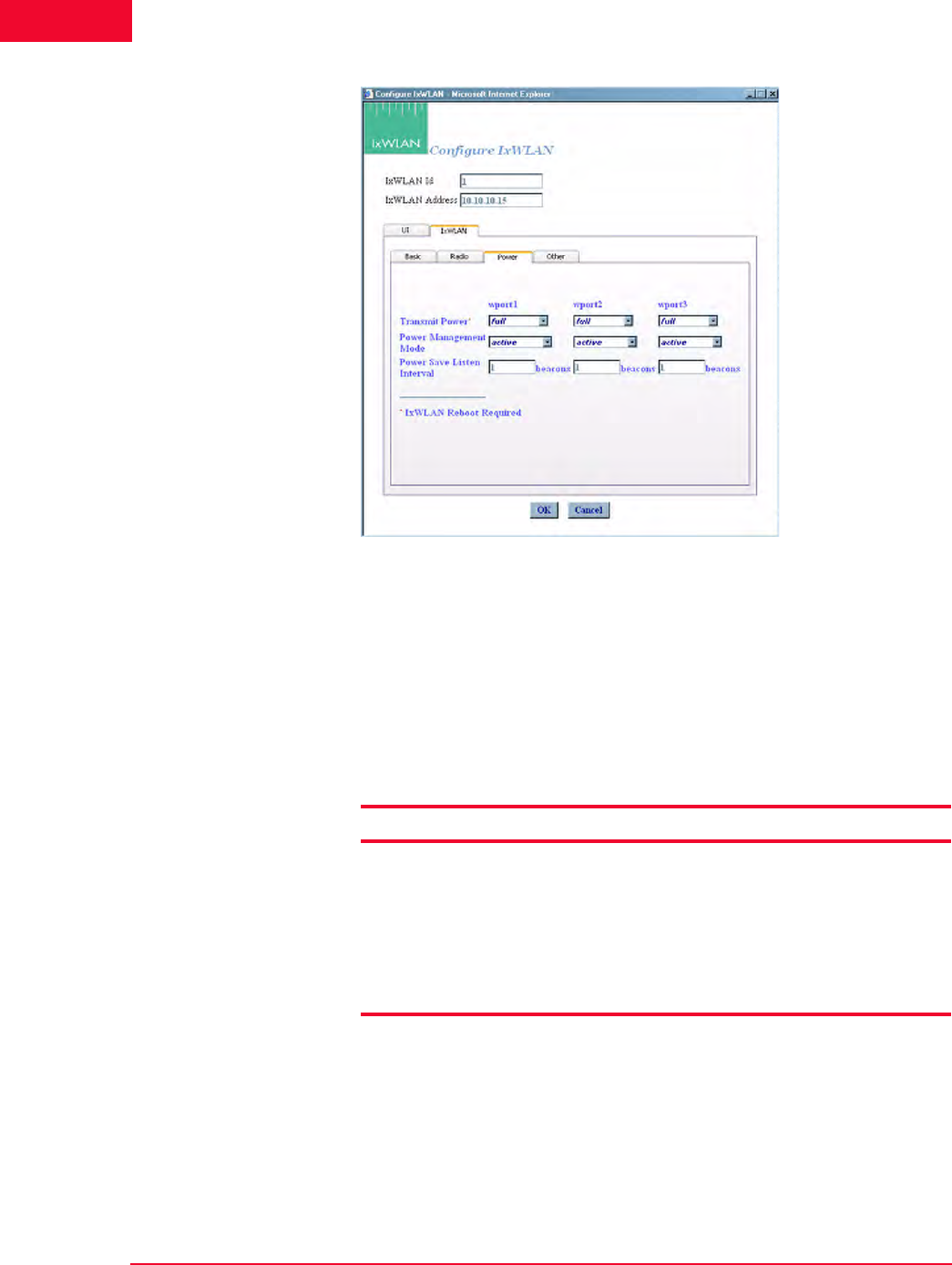
The Web-Based User Interface
IxWLAN Side Bar
4-50 IxWLAN User Guide, Release 6.20
4
Figure 4-60. IxWLAN Power
Transmit Power: Select full, half, quarter, eighth, or min from the list box.
The dBm/mW values in Table 4-1 are applicable only when the country code is
US. In other countries, power settings are relative to the maximum transmit
power available for the country. If you change the transmit power setting, you
must select the Reboot option from the IxWLAN side bar in order for the new
transmit power to be recognized and used in IxWLAN.
Table 4-1. Transmit Power Options
Power Management Mode: Select active (always awake) or power save (doze
for the specified listen interval) from the list box. See the notes later in this sec-
tion.
Power Save Listen Interval: Specify the listen interval in terms of the number of
beacons (1…100). The default value is 1.
Selection Description
full maximum (normal) transmit power (18 dBm/64 mW)
half fractional (1/2) transmit power (15 dBm/31.5 mW)
quarter fractional (1/4) transmit power (12 dBm/16 mW)
eighth fractional (1/8) transmit power (9 dBm/8 mW)
minimum minimum transmit power (3 dBm/2 mW)

IxWLAN User Guide, Release 6.20 4-51
The Web-Based User Interface
IxWLAN Side Bar
NOTES:
When the Power Management mode is set to Active, IxWLAN remains in the
awake state at all times. When the Power Management mode is set to Power
save, IxWLAN enters a dozing state until awakened by the listen interval. When
dozing:
•IxWLAN does not accept WLAN frames transmitted to any vSTA.
•IxWLAN awakens at each listen interval to receive the next beacon and poll
for frames buffered for any vSTA in accordance with the 802.11 Power Man-
agement needs.
•IxWLAN awakens at DTIM intervals to receive DTIM beacons when buffered
broadcast/multicast frames are indicated.
While in either state, any WLAN frames to be transmitted from any vSTA may be
immediately placed into the Transmit Queue for transmission by the WLAN
interface. Any transmission from any vSTA indicates the IxWLAN current Power
Management mode.
The beacon interval is determined by the System Under Test, usually by some
user-configurable parameter. IxWLAN receives beacons sent by the System
Under Test. A typical beacon rate is one every 100 Time Units. An 802.11 Time
Unit is defined as 1024 ms. So, the beacon rate would be one every 102.4 ms,
or about 10 per second. As an example, if the Power Management Mode is set
to Power Save and the Power Save Listen Interval is set to 3, IxWLAN wakes
up about every 307.2 ms to poll for frames queued in the System Under Test.

The Web-Based User Interface
IxWLAN Side Bar
4-52 IxWLAN User Guide, Release 6.20
4
IxWLAN->Configure IxWLAN->IxWLAN/Other
This section of the Configure IxWLAN dialog enables/disables the MIC check
on received TKIP-encrypted frames, as shown in Figure 4-61.
Figure 4-61. IxWLAN Other
MIC Check: Select Enable, Disable, or Spot from this list box. The MIC is an
integrity check that is run on all received TKIP data frames and is achieved via
the CPU-intensive Michael algorithm. This parameter allows the MIC check to
be temporarily disabled or reduced to spot checks (in that case, only every 16th
TKIP frame is checked). This applies to receive frames only. The MIC is always
calculated for transmit frames when using TKIP.
IxWLAN-
>Reconnect
IxWLAN
Reconnect is needed after reboot or if you become disconnected from IxWLAN
for any reason. The Reconnect IxWLAN button in the IxWLAN side bar opens
a confirmation dialog, as shown in Figure 4-62.
Figure 4-62. Reconnect Confirmation Dialog
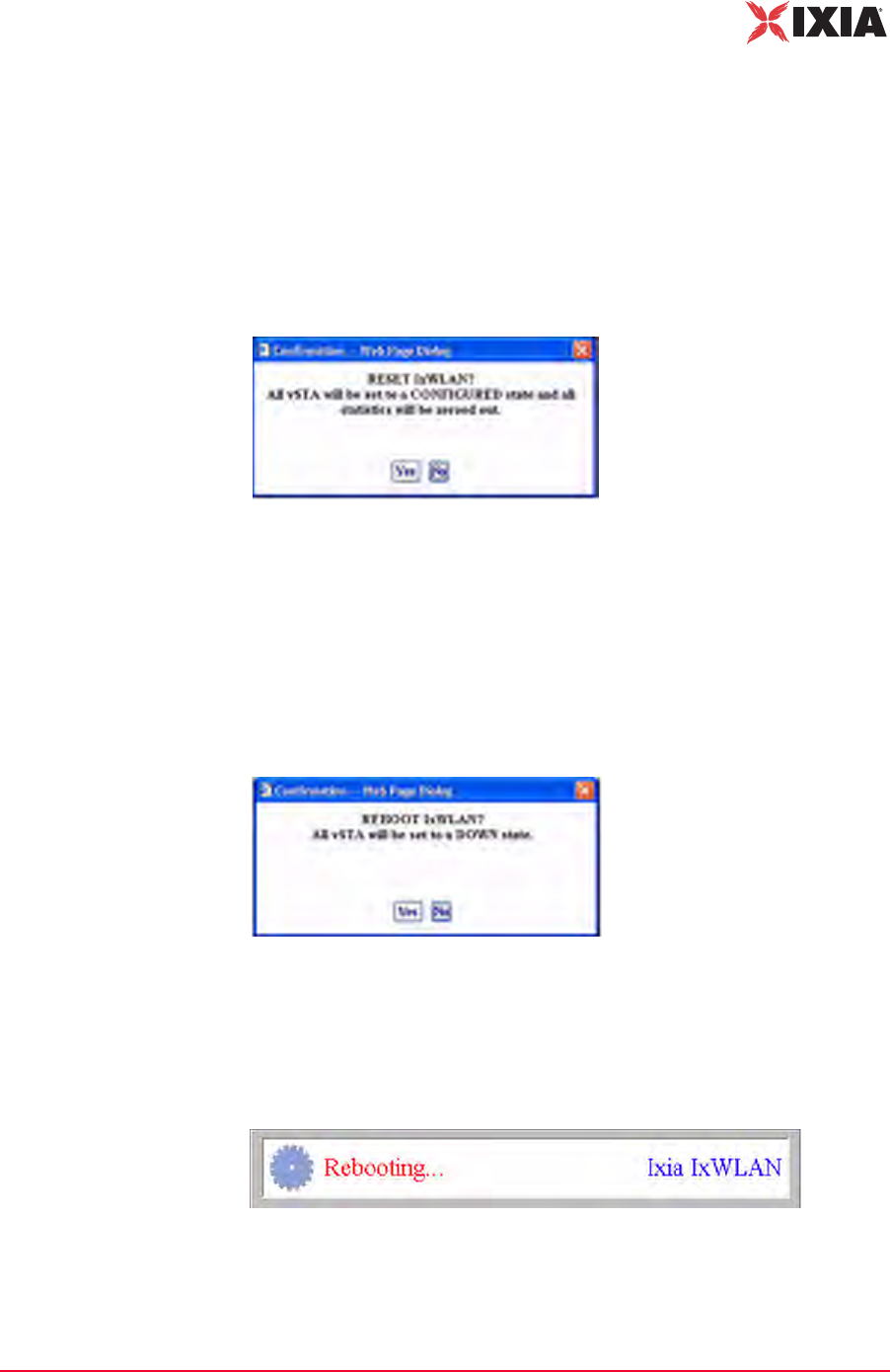
IxWLAN User Guide, Release 6.20 4-53
The Web-Based User Interface
IxWLAN Side Bar
•Click Ye s to reconnect to IxWLAN.
•Click No to cancel the reconnect selection.
Following successful reconnect, the web-based user interface restores the sce-
nario (if any) in IxWLAN.
IxWLAN->Reset
IxWLAN
The Reset IxWLAN button in the IxWLAN side bar opens a confirmation dialog
(Figure 4-63).
Figure 4-63. Reset Confirmation
•Click Yes to reset all virtual stations to a configured state and to reset all sta-
tistics counters to zero.
•Click No to cancel the reset selection.
IxWLAN->Reboot
IxWLAN
The Reboot IxWLAN button in the IxWLAN side bar opens a confirmation dia-
log (Figure 4-64).
Figure 4-64. Reboot Confirmation
•Click No to cancel the reboot operation.
•Click Yes to reboot IxWLAN. When Yes is clicked, the message shown in
Figure 4-65 displays.
Figure 4-65. Rebooting Dialog
This message box disappears when the reboot is complete.
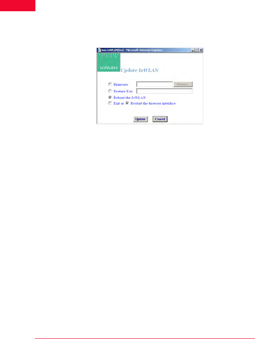
The Web-Based User Interface
IxWLAN Side Bar
4-54 IxWLAN User Guide, Release 6.20
4
IxWLAN->Update
IxWLAN
The Update IxWLAN button in the IxWLAN side bar or the Update IxW-
LAN… selection in the About menu opens the Update IxWLAN dialog, as
shown in Figure 4-66.
Figure 4-66. Update IxWLAN
Firmware: To update IxWLAN firmware, check this box and type the location of
the firmware image file on the command PC or select the Browse… button to
select the location on the command PC. The Firmware field must be a valid file
name with a SYS file type (case insensitive) and the file must exist on the com-
mand PC.
Feature Key: To update the IxWLAN feature key, check this box and type the
feature key hex string. The Feature Key must be an ASCII hex string containing a
valid feature key for this IxWLAN.
Reboot IxWLAN: Check this box to reboot IxWLAN after the new firmware
image or feature key is successfully loaded.
Exit or Restart the browser interface: Check the box next to Exit to exit the
web-based user interface after the new firmware image or feature key is success-
fully loaded. Check the box next to Restart to restart the web-based user inter-
face following successful IxWLAN update.
•Click the Update button to start IxWLAN Update.
•Click the Cancel button to exit the dialog.
If the dialog is not filled in correctly (for example, invalid or missing firmware
file, invalid feature key, and so on), the field is highlighted and an error message
dialog identifies the error.
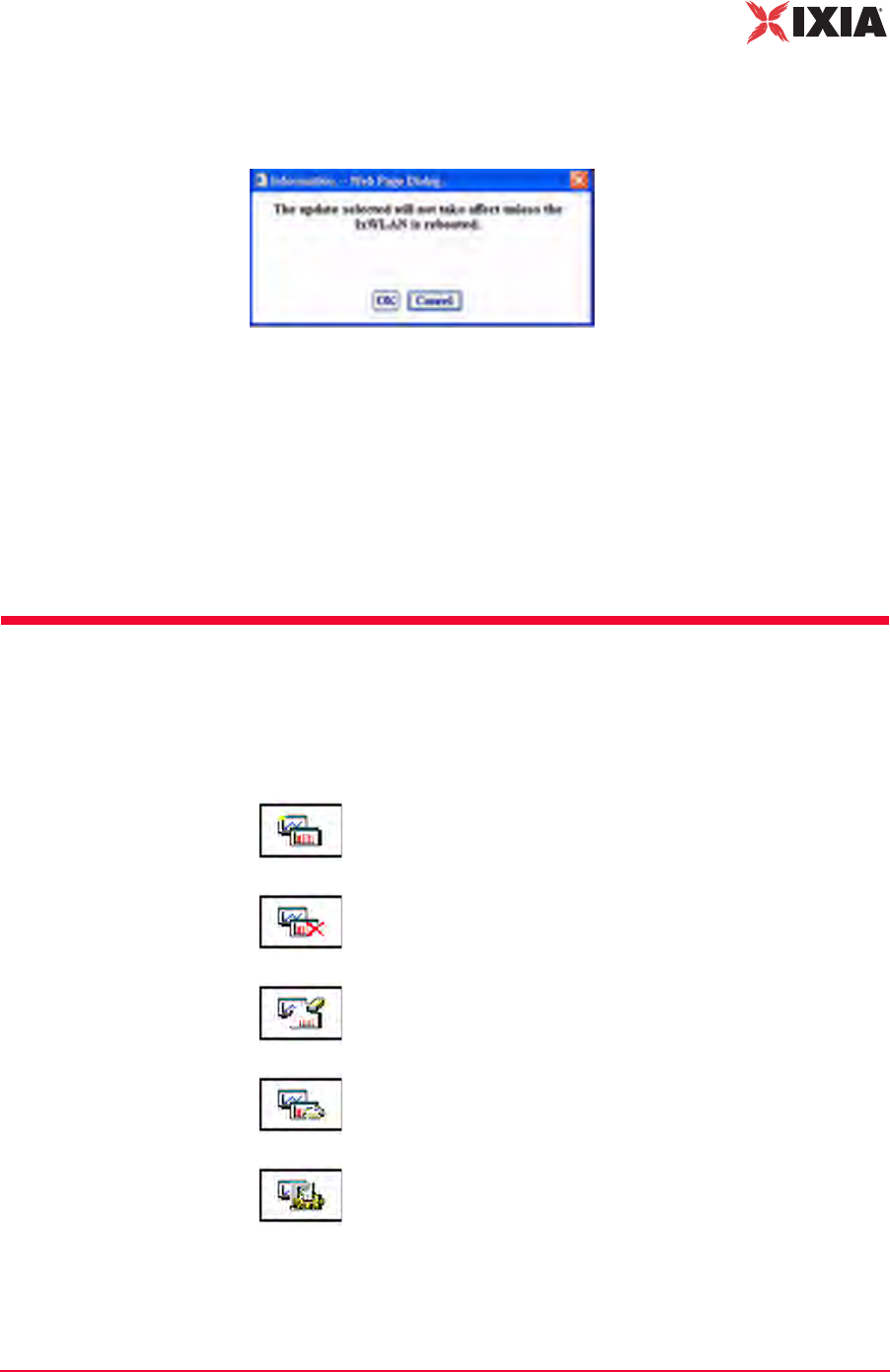
IxWLAN User Guide, Release 6.20 4-55
The Web-Based User Interface
Monitors Side Bar
If the Reboot IxWLAN checkbox is not clicked, a warning dialog opens, as
shown in Figure 4-67.
Figure 4-67. Warning Dialog
•Click OK to continue IxWLAN Update without rebooting.
•Click Cancel to return to the Update IxWLAN dialog.
If any errors occur during firmware update (for example, flash file system is full),
the error is reported in an error message dialog. If an invalid or corrupted firm-
ware image file is specified, the IxWLAN reboot fails. If this condition occurs,
the CLI must be used to correct the problem. See Recovering a Corrupted
Firmware File on page 8-9.
Monitors Side Bar
The Monitors side bar is used to define, delete, clear, export, and configure mon-
itors. After a monitor is defined using New Monitor, the bottom section of the
main page displays the statistics counters.
New Monitor: Defines a new monitor. You can define up to four
different monitors in each scenario.
Delete Monitor: Deletes the currently displayed monitor.
Clear Monitor: Clears the statistics counters in the currently
displayed monitor.
Export Monitor: Exports the statistics counters for one or more
monitors.
Config Monitors: Configures how monitors are maintained and
updated with data from IxWLAN.
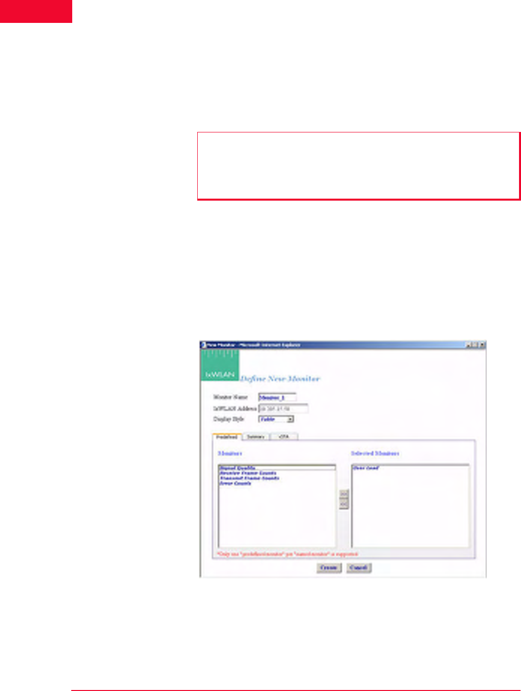
The Web-Based User Interface
Monitors Side Bar
4-56 IxWLAN User Guide, Release 6.20
4
A monitor is one or more user-selected statistics counters that the web-based user
interface collects from IxWLAN and displays in the user-selected format (that is,
line graph, bar graph, or table). All collected data can be exported. Monitors are
based on Line graphs, Bar graphs, and Tables. You can use them to monitor the
summary statistics of IxWLAN or a summary Master vSTA that shows virtual
station statistics across all virtual stations.
Monitors->New
Monitor
The New Monitor dialog is a tabbed dialog that can be used to define predefined,
summary, and summary virtual station counters to be maintained during the exe-
cution of a test.
Monitors->New Monitor->Predefined
Use the Predefined section of the Define New Monitor dialog to select predefined
statistics counters, as shown in Figure 4-68.
Figure 4-68. Define Monitor Dialog
Monitor Name: Type a monitor name. It can be up to 12 characters (a…z, 0…9,
and underscore (_)).
IxWLAN Address: Shows IxWLAN's IP address.
NOTES:
•Each scenario can include up to four different monitors.
•Monitor values are stored in memory on the command PC. If you run one or
more monitors for an extended period of time, available memory may
become depleted and this can affect the performance of the command PC.
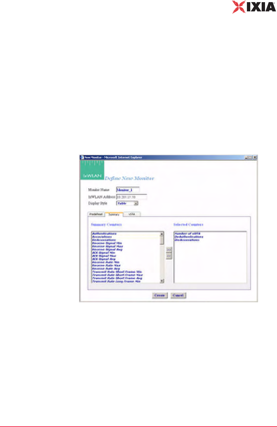
IxWLAN User Guide, Release 6.20 4-57
The Web-Based User Interface
Monitors Side Bar
Display Style: Select a display style from the list box. It can be one of the follow-
ing: Line Graph, Bar Graph, or Table.
Monitors->Selected Monitors: Select one of the monitors to be maintained. Use
the [>>] button (or double-click the line item) to transfer the predefined monitor
to the Selected Monitors column. See Chapter 7, Statistics Counters for a
description of each of these statistics counters.
•Click the Create button to create and display the monitor.
•Click the Cancel button to close this dialog.
Monitors->New Monitor->Summary
Use the Summary section of the Define New Monitor dialog to select summary
statistics counters, as shown in Figure 4-69.
Figure 4-69. Summary
Summary Counters->Selected Counters: Select one or more of the counters to be
maintained in the test results file. Use the [>>] button to transfer the counters to
the Selected Counters column. See Chapter 7, Statistics Counters for a descrip-
tion of each of these statistics counters.
•Click the Create button to create and display the monitor.
•Click the Cancel button to close this dialog.
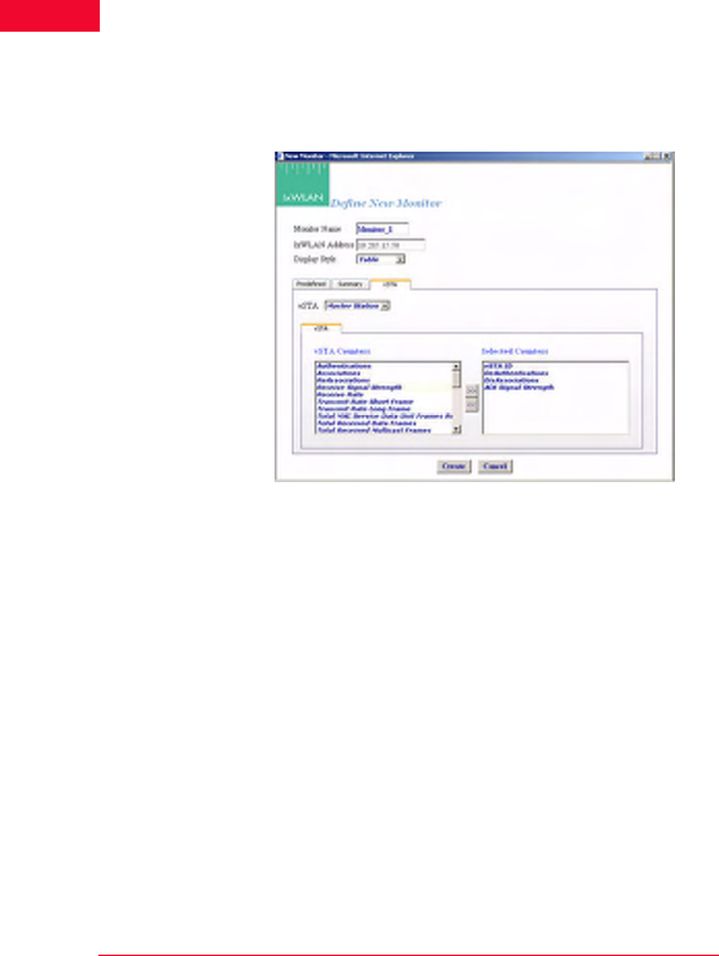
The Web-Based User Interface
Monitors Side Bar
4-58 IxWLAN User Guide, Release 6.20
4
Monitors->New Monitor->vSTA
Use the vSTA section of the Define New Monitor dialog to select the master
(summary) virtual station statistics counters, as shown in Figure 4-70.
Figure 4-70. vSTA Section
vSTA (s): Select a virtual station from the list box. The Master Station is a sum-
mary that shows virtual station statistics across all virtual stations.
vSTA Counters->Selected Counters: Select one or more of the counters to be
maintained in the test results file. Use the [>>] button to transfer the counters to
the Selected Counters column. See Chapter 7, Statistics Counters for a descrip-
tion of each of these statistics counters.
•Click the Create button to create and display the monitor.
•Click the Cancel button to close this dialog.
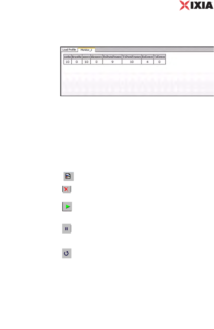
IxWLAN User Guide, Release 6.20 4-59
The Web-Based User Interface
Monitors Side Bar
When you select one or more counters and choose the Create button, the bottom
half of the screen shows the current results in the selected display style, as shown
in Figure 4-71.
Figure 4-71. More Counters Selected
As you run scenario tests, the monitors update with current data from IxWLAN.
For chart display styles, the legends on the right side of the monitor indicate the
statistics counters selected in the New Monitor dialog. For table display styles,
the table headings indicate the statistics counters selected in the New Monitor
dialog. See Chapter 7, Statistics Counters for a description of each of these statis-
tics counters. The tool bar buttons on the right side of the monitor display can be
used for the following functions:
For more information about these buttons, please refer to Monitor Tool Bar on
page 4-81.
New Monitor: Defines a new monitor.
Delete: Allows you to delete a monitor. A dialog opens, asking you to
confirm the selection.
Run: Runs a monitor. When the Run Monitor button is selected, the
currently displayed monitor starts gathering and displaying its target
statistics.
Pause: Pauses a monitor. When the Pause Monitor button is
selected, the currently displayed monitor stops its target statistics.
However, statistics are accumulated in the background and can be
exported.
Clear: Clears a monitor. A dialog opens, asking you to confirm the
selection. This selection sets all counters in the current monitor to zero.
Statistics gathered up to this point are not cleared and are still
exportable.

The Web-Based User Interface
Monitors Side Bar
4-60 IxWLAN User Guide, Release 6.20
4
Monitors->Delete
Monitor
The Delete Monitor button in the Monitors side bar or the monitor tool bar
opens a confirmation dialog, as shown in Figure 4-72.
Figure 4-72. Delete Monitor Confirmation
•Click Yes to delete the current monitor.
•Click No to cancel the delete selection.
Monitors->Clear
Monitor
The Clear Monitor button in the Monitors side bar or the Monitor tool bar
opens a confirmation dialog, as shown in Figure 4-73.
Figure 4-73. Clear Monitor Confirmation
•Click Yes to clear the monitor. All the counters in the monitor are set to zero.
Statistics gathered up to this point are not cleared and can still be exported.
•Click No to close this dialog without clearing the monitor.
Monitors->Export
Monitor
The function is used to export the collected statistics in a defined monitor. For
export, the data obtained from the monitor is saved.
NOTE: For all graphs, each tick saves the information of each field that is
requested. This can grow large depending on how long the monitor has run. An
artificial limit of one hour has been enforced to clear this saved data. At the end
of each hour, this stored data array is cleared.
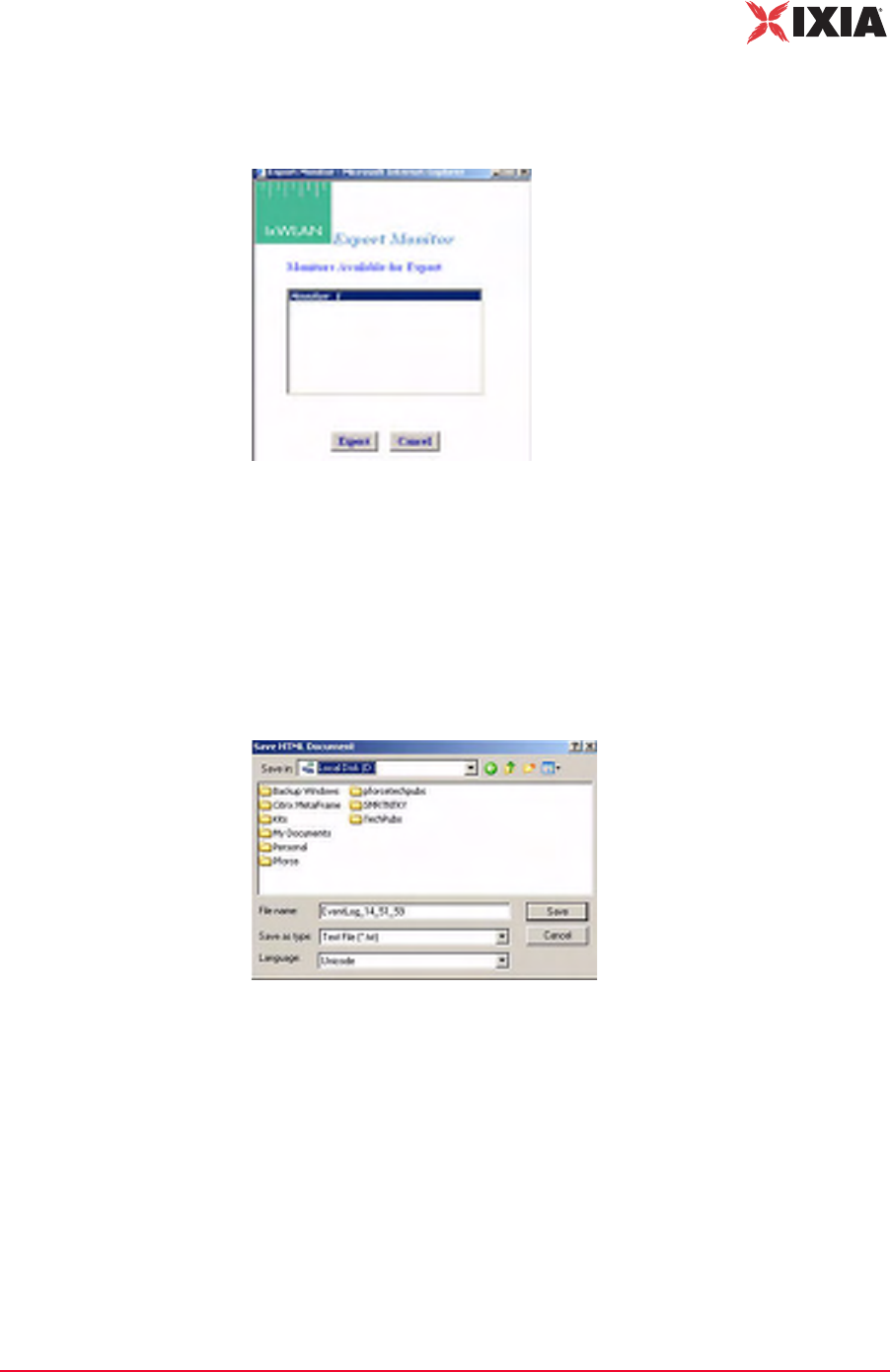
IxWLAN User Guide, Release 6.20 4-61
The Web-Based User Interface
Monitors Side Bar
The Export Monitor button in the Monitors side bar opens the Export Monitor
dialog, as shown in Figure 4-74.
Figure 4-74. The Export Monitor Dialog
Select one or more monitors in the list box.
•Click the Export button to export the monitors in the Selected Monitors list
box.
•Click the Cancel button to close this dialog without exporting monitors.
The Export button opens the Save HTML Document dialog, as shown in Figure
4-75.
Figure 4-75. Save HTML Document
Identify the name of the file where you want to save the monitor information.
•Click the Save button to save the information to the specified file.
•Click the Cancel button to exit this dialog without exporting any data.
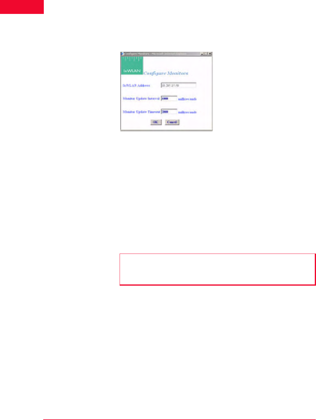
The Web-Based User Interface
Monitors Side Bar
4-62 IxWLAN User Guide, Release 6.20
4
Monitors->Config
Monitors
The Config Monitors button in the Monitors side bar opens the Configure Mon-
itors dialog, as shown in Figure 4-76.
Figure 4-76. Configure Monitors Dialog
IxWLAN Address: Shows the IP address of IxWLAN.
Monitor Update Interval: Defines the interval (in milliseconds) that the Com-
mand PC polls IxWLAN for new statistics counters. It can be set to a value in the
250 to 60000 ms (1 min) range. Any value under 1000 ms is not advisable and
may affect performance significantly. If you notice any issues with update per-
formance, try increasing this value.
Monitor Update Timeout: Defines the time (in milliseconds) that the Command
PC waits for a response from IxWLAN. It can be set to a value in the 500 to
120000 ms (2 min) range. The recommended value is twice the Monitor Update
Interval value. If this time expires without an expected response from IxWLAN,
the web-based user interface tries to restart the monitor update timer.
•Click OK to save the monitor configuration.
•Click Cancel to close the dialog.
NOTE: Also see the IxWLAN Polling Interval and IxWLAN Polling Timeout in
IxWLAN->Configure IxWLAN on page 4-44 for the interval and update timeout
values that are used by the command PC to send command and control
information to IxWLAN.
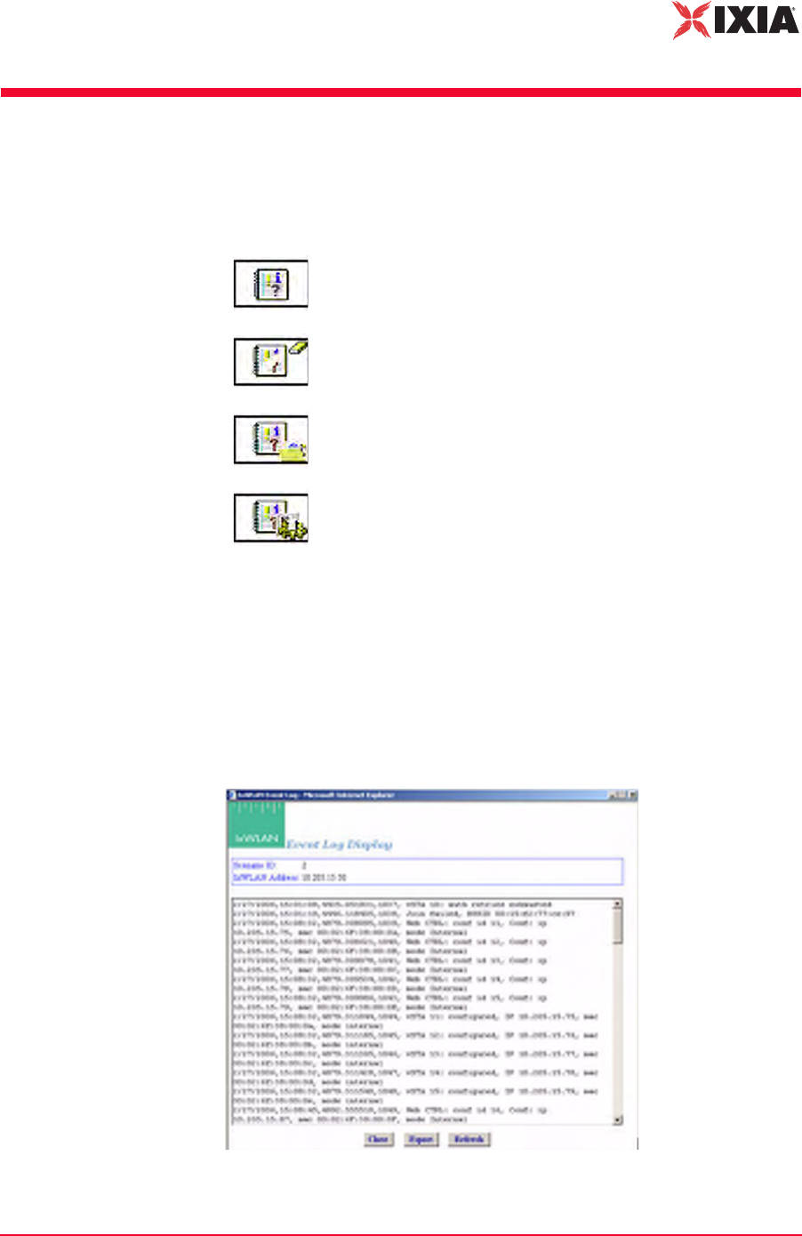
IxWLAN User Guide, Release 6.20 4-63
The Web-Based User Interface
Event Log Side Bar
Event Log Side Bar
The buttons in the Event Log side bar are used to display, clear, export, and con-
figure the Event Log as follows:
For more information about how IxWLAN creates and maintains the event log,
please refer to Appendix B, Event Logging.
Event Log->Event
Log
When the Event Log button is selected in the Event Log side bar, the web-based
user interface begins retrieving event log records from IxWLAN. The following
message opens in the Event Log window: “Retrieving up to the last 100
records…”. Figure 4-77 shows the format of event records retrieved from IxW-
LAN.
Figure 4-77. Event Log
Event Log: Shows the last 100 event log entries.
Clear Log: Clears the current contents of the event log.
Export Log: Exports the last 100 event log entries to a file.
Configure Log: Configures event logging.
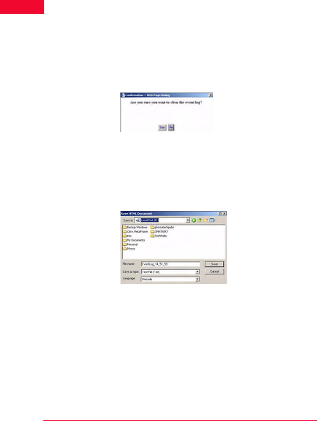
The Web-Based User Interface
Event Log Side Bar
4-64 IxWLAN User Guide, Release 6.20
4
•Click the Close button to close this dialog.
•Click the Export button to export this event log information to a file.
•Click the Refresh button to update the dialog with new events.
Event Log->Clear
Log
The Clear Log button in the Event Log side bar opens a confirmation dialog, as
shown in Figure 4-78.
Figure 4-78. Clear Log Confirmation
•Click Yes to clear the event log.
•Click No to exit this dialog without clearing the event log.
Event Log->Export
Log
The Export Log button in the Event Log side bar opens a Save HTML Docu-
ment dialog, as shown in Figure 4-79.
Figure 4-79. Export Log
Identify the name of the file where the log is to be written.
•Click the Save button to save the event log in a file.
•Click the Cancel button to exit this dialog.

IxWLAN User Guide, Release 6.20 4-65
The Web-Based User Interface
Event Log Side Bar
Event Log-
>Configure Log
The Configure Log button in the Event Log side bar opens the Event Log Con-
figuration dialog, as shown in Figure 4-80.
Figure 4-80. Configure Log
IxWLAN Address: Defines the IP address of IxWLAN where the log file resides.
Logging: Enables/disables event logging.
Logging to Console: Enables/disables event logging to the CLI console. When
Logging to Console is enabled (checked), event data is posted to the console con-
nected to IxWLAN's serial port (if available). The web-based user interface can-
not be used to enable logging to a telnet session.
Logging to File: Enables/disables event logging to a file in the IxWLAN flash
file system.
Clear Event Log on Reset: The checkbox enables/disables clearing the event log
when the scenario is reset.
Log Verbosity: The verbosity level sets thresholds for which events are to be
logged: at higher verbosity, more events are logged; at lower verbosity, fewer
events are logged. Select Critical, Low, Medium, or High from the list box.
Modules Logged: Select one or more modules (system processes) from which
event messages of the selected level should be collected.
•Click OK to close this dialog and save the event log configuration.
•Select Cancel to close this dialog without saving event log configuration.

The Web-Based User Interface
Reports Side Bar
4-66 IxWLAN User Guide, Release 6.20
4
Reports Side Bar
The options in the Reports side bar can be used to display statistics counters that
are maintained by IxWLAN during the execution of a test.
IxWLAN Configuration: Opens the IxWLAN configuration report.
Scenario Summary: Shows summary statistics of IxWLAN and
all virtual stations.
Group Summary: Shows summary statistics of a scenario group.
vSTA Master: Shows statistics collected for all virtual stations.
wport: Shows statistics collected per wport.
vSTA Detailed: Shows detailed statistics counters for each virtual
station.
Export Reports: Exports/views reports in a CSV file format
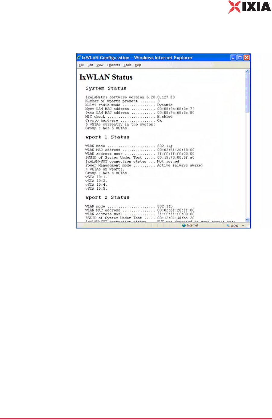
IxWLAN User Guide, Release 6.20 4-67
The Web-Based User Interface
Reports Side Bar
Reports->IxWLAN
Configuration
The IxWLAN Configuration button in the Reports side bar displays the IxW-
LAN Configuration Report, as shown in Figure 4-81.
Figure 4-81. IxWLAN Configuration Report
This report shows the status and configuration of IxWLAN. If WPA/RSN is
enabled, the status section of the report includes an indication of the cumulative
crypto hardware status (that is, Crypto hardware…OK). If any faults have been
detected in a self-test, the status shown indicates this condition (for example,
Crypto hardware…Faulted, run the cryptotest CLI command for details).
Reports->Scenario
Summary
The Scenario Summary button in the Reports side bar opens the Summary Sta-
tistics (Scenario) Report, as shown in Figure 4-82 on page 4-68.
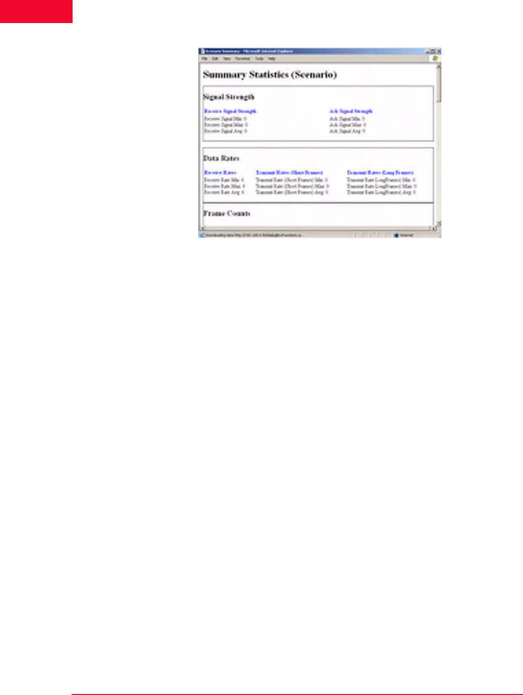
The Web-Based User Interface
Reports Side Bar
4-68 IxWLAN User Guide, Release 6.20
4
Figure 4-82. Scenario Summary Report
Summary statistics give a summary report taken over a set of virtual stations. The
virtual station set can be a defined group or all virtual stations currently in the
system. By contrast, the individual virtual station statistics report gives a list of
statistics and counters for all virtual stations. The summary report gives a sum-
mary of the statistics and counters taken over the indicated set of virtual stations.
The summary gives, for each counter, the minimum and maximum values for
that counter found in the set of examined virtual stations, the average value, and
where applicable, the (sum) total over the set of virtual stations. The Avg fields
(that is, Receive Rate Avg, Transmit Rate (Short Frame) Avg, and Transmit Rate
(Long Frame) Avg) in the Data Rate section of the summary statistics display is
the average rate for the master vSTA since the time IxWLAN joined to a System
Under Test. For more information about the statistics counters that can be shown
in this report, please refer to Chapter 7, Statistics Counters.
Reports->Group
Summary
The Group Summary button in the Reports side bar opens the Summary Statis-
tics (Group #) Report, as shown in Figure 4-83 on page 4-69.
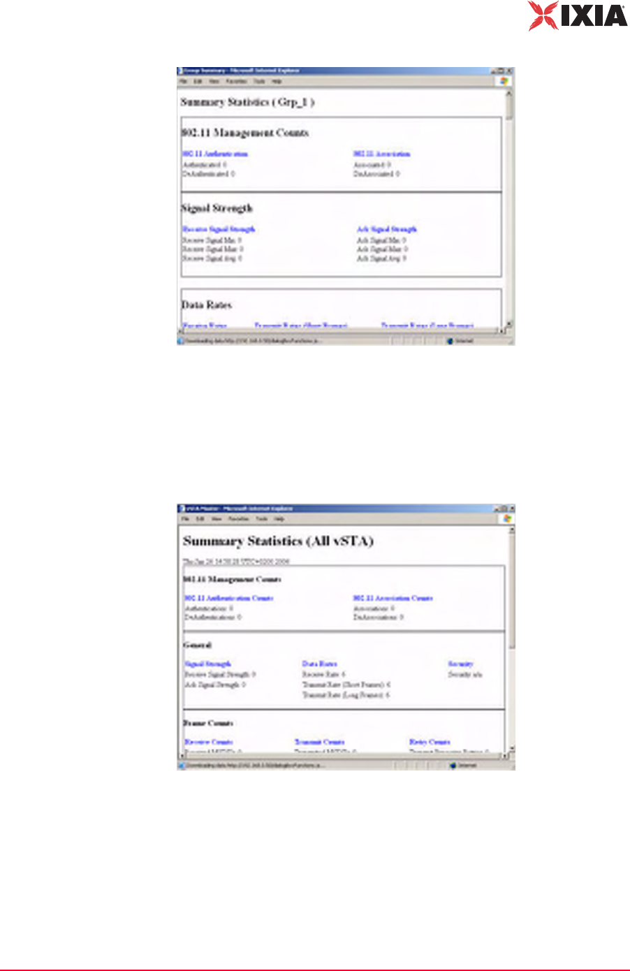
IxWLAN User Guide, Release 6.20 4-69
The Web-Based User Interface
Reports Side Bar
Figure 4-83. Group Summary Report
For more information about the statistics counters that can be displayed in this
report, please refer to Chapter 7, Statistics Counters.
Reports->vSTA
Master
The vSTA Master button in the Reports side bar opens the Summary Statistics
(All vSTA) Report, as shown in Figure 4-84.
Figure 4-84. vSTA Master Report
For more information about the statistics counters that can be shown in this
report, please refer to Chapter 7, Statistics Counters.
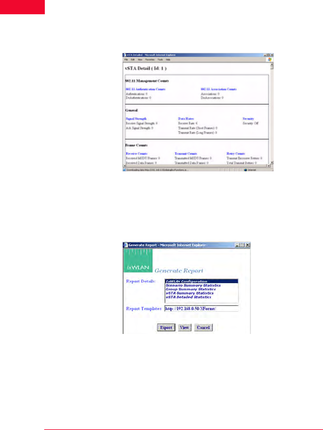
The Web-Based User Interface
Reports Side Bar
4-70 IxWLAN User Guide, Release 6.20
4
Reports->vSTA
Detail
The vSTA Detail button in the Reports side bar opens the vSTA Detail Report,
as shown in Figure 4-85.
Figure 4-85. vSTA Detail Report
For more information about the statistics counters that can be shown in this
report, please refer to Chapter 7, Statistics Counters.
Reports->Export
Reports
The Export Reports button in the Reports side bar opens the Generate Report
dialog, as shown in Figure 4-86.
Figure 4-86. Export Reports
Report Details: Select one or more reports to export in the Report Details list
box.
Report Templates: Defines the directory/path where XML transform files are
retrieved. These XSLT files are then used to create reports from the XML data
returned by IxWLAN. By specifying another directory path, you can customize
reports to suit your needs.
IxWLAN User Guide, Release 6.20 4-71
The Web-Based User Interface
Configuration Side Bar
•Click the Export button to export the report(s) to a comma-separated values
(.CSV) file.
•Click the View button to show the selected report(s).
•Click the Cancel button to exit this dialog.
Configuration Side Bar
The buttons in the Configuration side bar are used to define default security,
default ping settings, the appearance of the web-based user interface, and avail-
able certificates.
Configuration-
>Security
The Security Configuration dialog, shown in Figure 4-87 on page 4-72, sets the
default security settings that can be used when a new group is created.
Security: Defines default security settings that can be used when
a group or virtual stations is configured.
Ping Defaults: Defines a default ping target, ping packet length,
and number of iteration values.
Preferences: Configures the appearance of the web-based user
interface.
Available Certificates: Transfers certificate files from the
command PC to IxWLAN, where they can be used by virtual
stations.
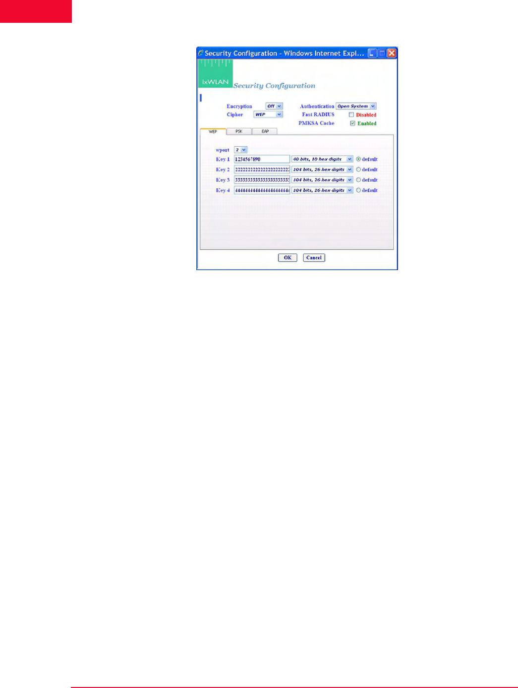
The Web-Based User Interface
Configuration Side Bar
4-72 IxWLAN User Guide, Release 6.20
4
Figure 4-87. Configuration Security
Encryption: Select On or Off from the drop-down list box to enable/disable
encryption.
Authentication: Select an authentication type: Open System, Shared Key, RSN,
RSN-PSK, WPA, or WPA-PSK. If you select RSN or WPA, define user cre-
dential parameters in the EAP tab. If you select RSN-PSK or WPA-PSK, define
a pre-shared key or passphrase in the PSK tab.
Cipher: For Open System or Shared Key Authentication, WEP is the only valid
selection. For RSN, RSN-PSK, WPA, and WPA-PSK Authentication, select
TKIP or AES-CCM (that is, CCMP cipher mode).
Fast Radius: The default value of this attribute is Disabled. When a vSTA is con-
figured for fast RADIUS reconnection and the vSTA has cached the TLS session
information, it tries fast resumption in subsequent 802.1X authentication
exchanges by using the session_id and master_key from the cached TLS session.
PMKSA Cache: Enables the use of the cached PMKSA information when
(re)associating. The default value is Enabled. Each entry in the PMKSA cache
contains the BSSID of the corresponding AP, a PMKID, and the Pairwise Master
Key (PMK). A PMKSA can be obtained by 802.1X authentication or by pre-
authentication.
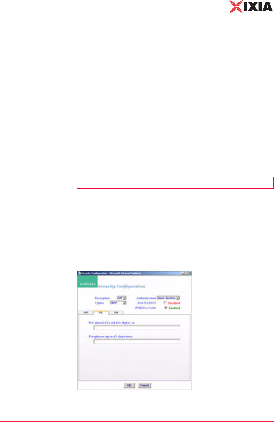
IxWLAN User Guide, Release 6.20 4-73
The Web-Based User Interface
Configuration Side Bar
Configuration->Security WEP Tab
The WEP tab in this dialog is used to define up to four shared keys for WEP
security. WEP encrypts data using an RC4 stream cipher seeded with a key of 40,
104, or 128 bits plus a 24-bit initialization vector, before transmission to the
wireless network. If you change any of the fields, you must click Reboot from
the IxWLAN side bar in order for the new encryption selections to be recognized
and used by IxWLAN.
wport: Choose the wport to which these selections are to apply.
Key 1…4: Each shared key can be 40, 104, or 128 bits. If 40 is selected in the list
box, you must type 10 hex digits. If 104 is selected in the list box, you must type
26 hex digits. If 128 is selected in the list box, you must type 32 hex digits. These
keys are shown in the Security section of the New IxWLAN Group dialog, the
Edit IxWLAN Group dialog, and the Add vSTA to Group dialog.
default: Select one of these radio buttons to identify which key(s) should be used
as default.
•Click OK to save the security settings to IxWLAN.
•Click Cancel to close this dialog without saving this security configuration.
Configuration->Security PSK Tab
If WPA-PSK or RSN-PSK is selected in the Authentication field, this section of
the dialog defines a Pre-Shared Key or passphrase, as shown in Figure 4-88.
Figure 4-88. Configuration Security PSK Tab
NOTE: To delete a key, remove the key from the field.
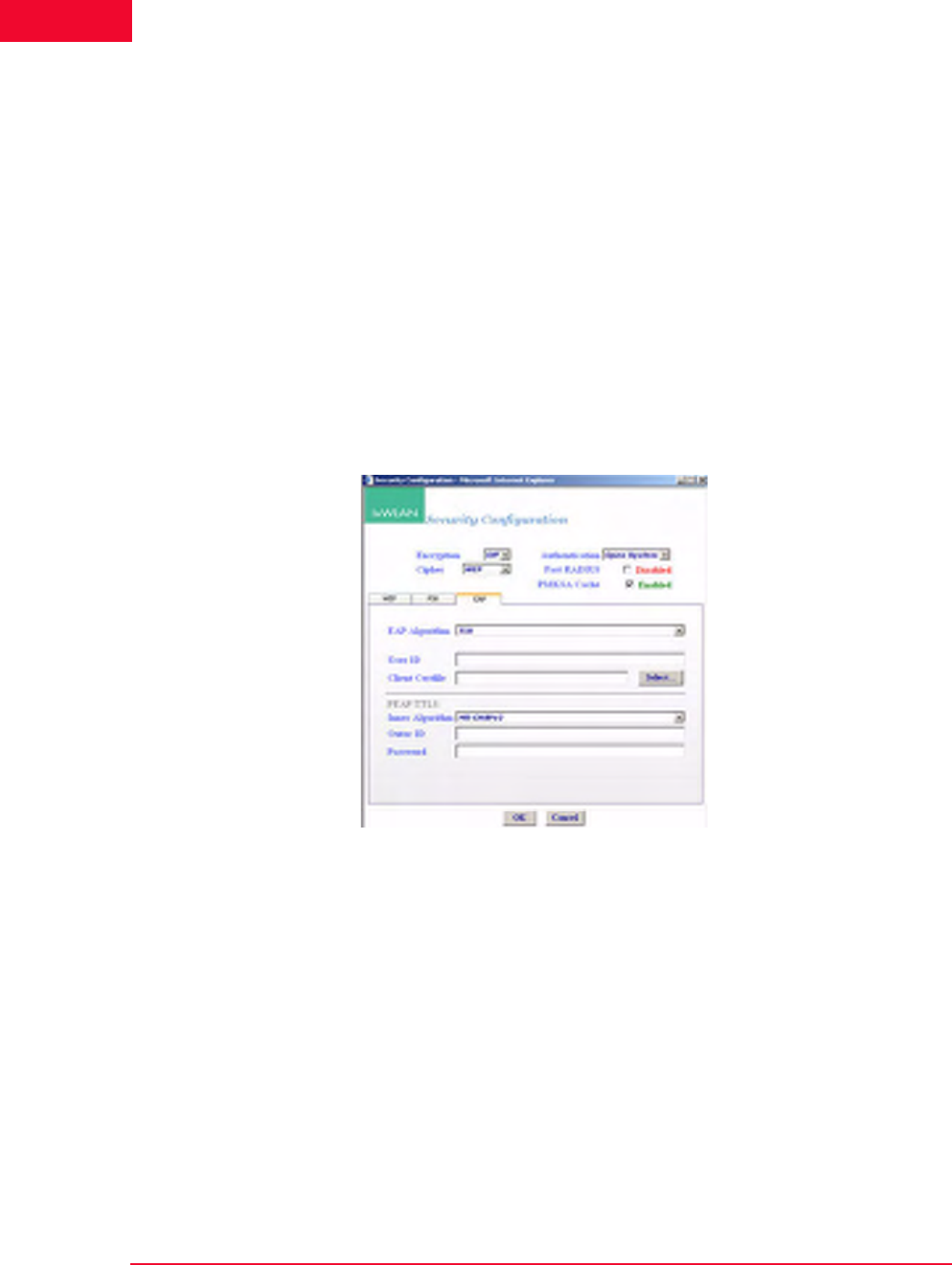
The Web-Based User Interface
Configuration Side Bar
4-74 IxWLAN User Guide, Release 6.20
4
Pre-Shared Key (64 hex digits): Defines a Pre-Shared Key (64 ASCII-hex char-
acters) for all virtual stations in this group. If using a Pre-Shared Key, it is not
necessary to specify the passphrase.
Passphrase (up to 63 characters): Defines a passphrase of up to 63 ASCII charac-
ters. If a passphrase is defined, it is not necessary to specify the Pre-Shared Key.
The passphrase is used to generate the Pre-Shared Key.
•Click OK to save this information to IxWLAN.
•Click Cancel to close this dialog without saving this security configuration.
Configuration->Security EAP Tab
If WPA or RSN is selected in the Authentication field, the Security EAP tab
allows you to define an EAP Algorithm, user ID and certificate file, and PEAP/
TTLS parameters, as shown in Figure 4-89.
Figure 4-89. Security EAP Tab
Inner Algorithm: Select MS-CHAPv2 or EAP-MS-CHAPv2 from the list box.
MS-CHAPv2 is normally used for TTLS, while EAP-MS-CHAPv2 is normally
used for PEAP.
User ID: Sets the user ID that is used as default for all virtual stations when a
new group is created. It can be up to 64 characters in the range A…Z, a…z, 0…9,
or other legal characters: period (.), dash (-), at-sign (@).
Client Certfile: Sets the certificate file that is used as the default for all virtual
stations when a new group is created.
Select…: Click the Select… button to open the Available Certificates dialog and
select the certificate file to use. See Available Certificates on page 4-36.
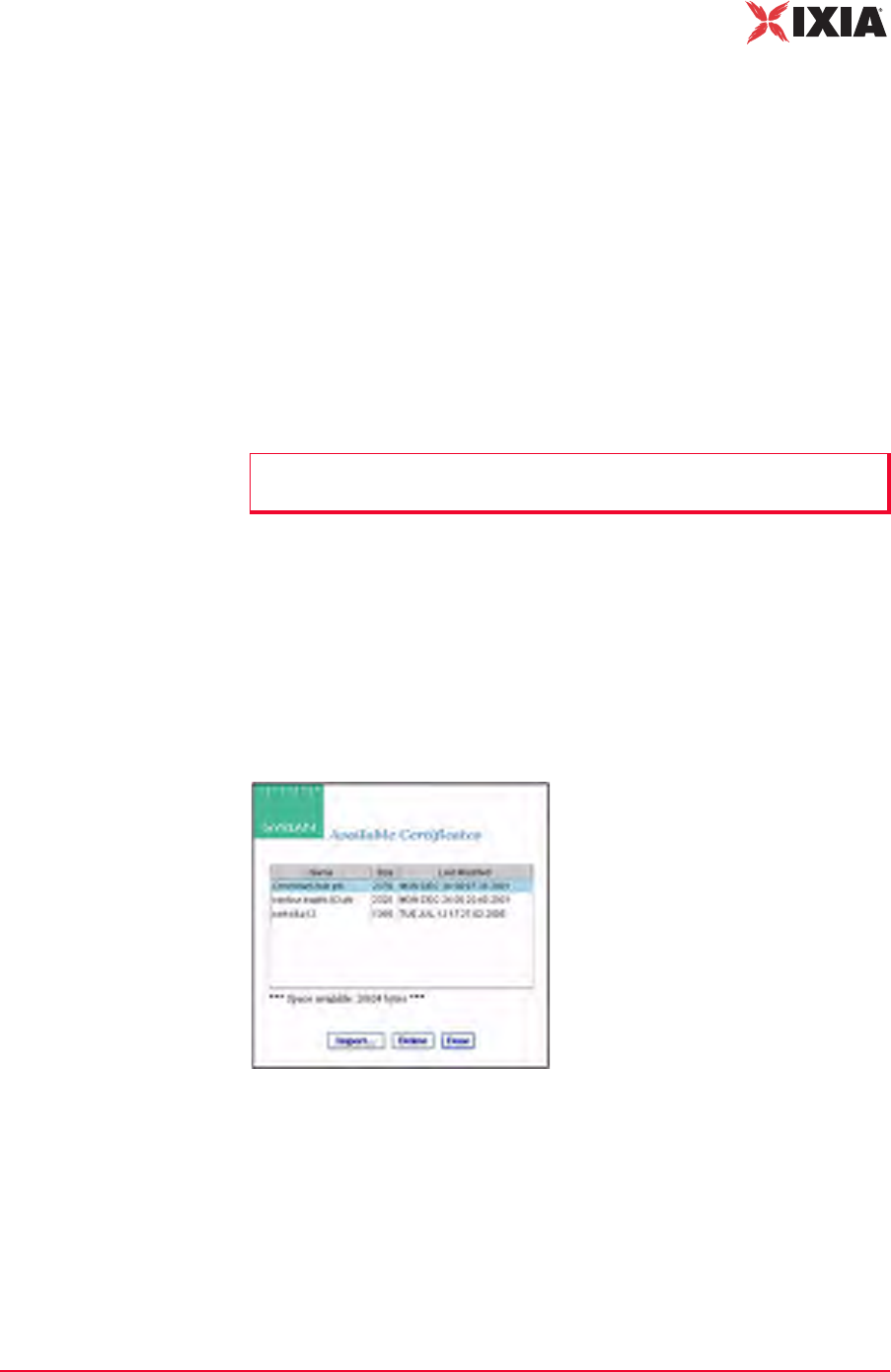
IxWLAN User Guide, Release 6.20 4-75
The Web-Based User Interface
Configuration Side Bar
PEAP/TTLS Parameters: When PEAP or TTLS is selected in the EAP Algo-
rithm list box, use this section of the dialog to define the PEAP/TTLS parame-
ters.
EAP Algorithm: Select the EAP algorithm to be used in Phase 2 authentication.
MS-CHAPv2 is normally used for TTLS. EAP-MS-CHAPv2 is normally used
for PEAP.
Outer ID: Type an outer identity to be used in Phase 1 authentication. It can be up
to 64 characters in the range A…Z, a…z, 0…9, or other legal characters: period
(.), dash (-), at-sign (@).
Password: Type a password to be used in Phase 2 authentication. It can be up to
64 characters.
•Click OK to save this information to IxWLAN.
•Click Cancel to close this dialog without saving this security configuration.
Available Certificates
The Select button in the Security Configuration/EAP tab opens the Available
Certificates dialog, as shown in Figure 4-90.
Figure 4-90. Available Certificates
The Space available indicates the total space available in the IxWLAN flash file
system. This number changes when certificate files are added or deleted.
•Click the OK button (or double-click a file name in the list) to set the Client
Certfile field to the currently highlighted certificate file name.
•Click the Delete button to delete the currently highlighted certificate file. A
confirmation dialog opens, asking you to confirm this selection. An error dia-
NOTE: Inner Algorithm, Outer ID, and Password are used only for TTLS and
PEAP. They are ignored for TLS.
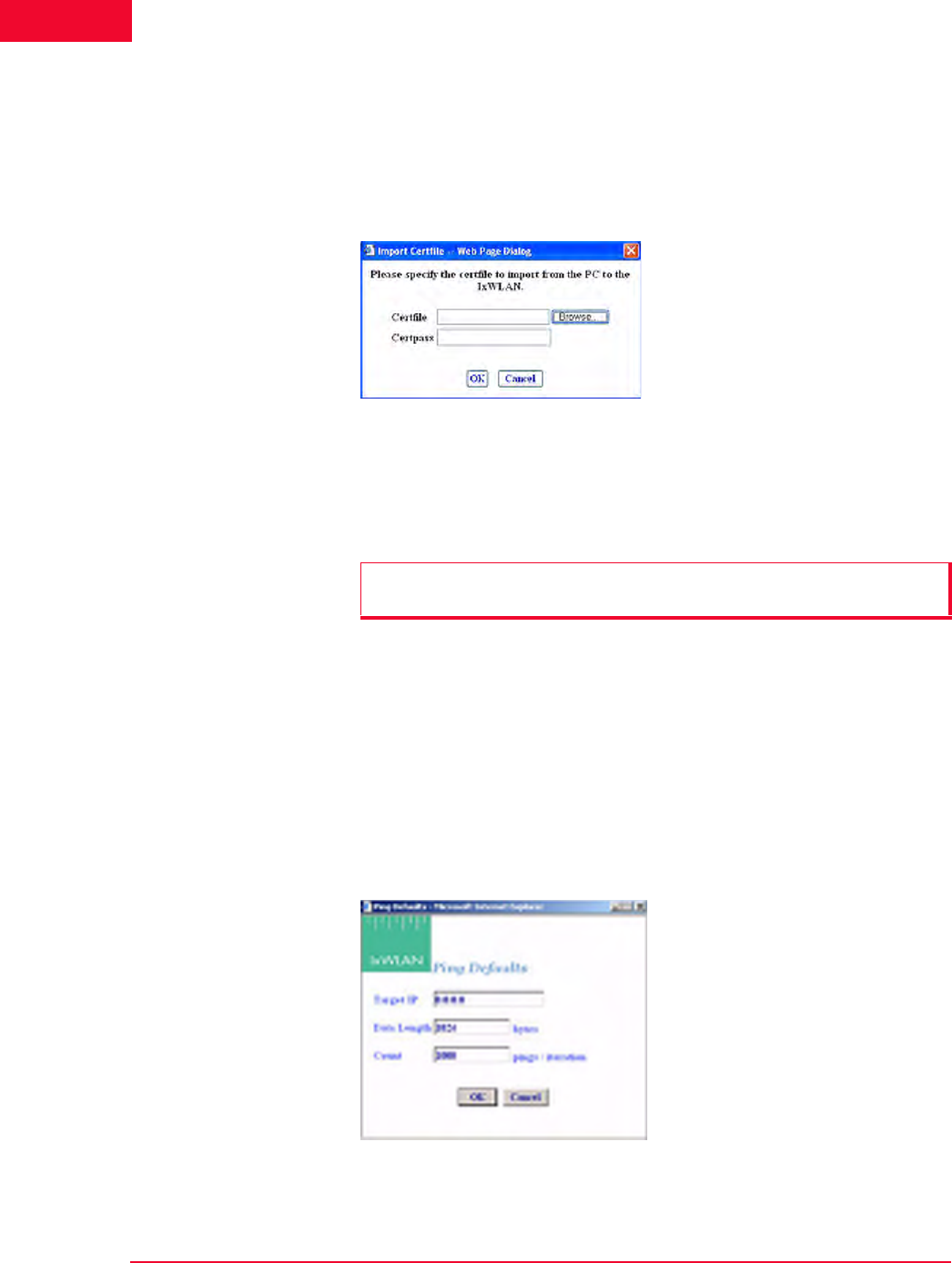
The Web-Based User Interface
Configuration Side Bar
4-76 IxWLAN User Guide, Release 6.20
4
log opens if the certificate file is in use by any vSTA, or otherwise the certifi-
cate file is deleted.
•Click the Cancel button to exit the dialog.
•Click the Import… button to open the Import Certfile dialog, as shown in
Figure 4-91 on page 4-76.
Figure 4-91. Import Certfile
Certfile: Type the complete path and name of a certificate file or click the
Browse… button to open the File Browse dialog and select from the files stored
on the command PC.
Certpass: After a file name is typed or selected, type the password that is needed
for the certificate file.
•Click OK to transfer the specified file to IxWLAN with the same file name
and extension. The newly-added certificate file is then listed as one of the
available certificates.
•Click Cancel to close this dialog without selecting a certificate file.
Configuration->Ping
Defaults
The Ping Defaults button in the Configuration side bar opens the Ping Defaults
dialog, as shown in Figure 4-92.
Figure 4-92. Ping Defaults Dialog
NOTE: Certificate files must be in PKCS#12 format, which is usually indicated
by a .p12 or a .pfx file extension
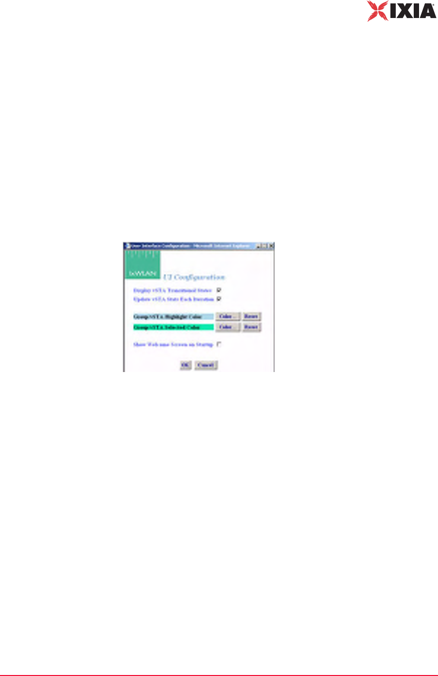
IxWLAN User Guide, Release 6.20 4-77
The Web-Based User Interface
Configuration Side Bar
Any changes made in this dialog affect all future group/virtual station creation
defaults for this session.
Target IP: Type the target IP address where ICMP Echo (Ping) Request/
Response messages should be sent.
Data Length: Specify the size (64…1024) of each message.
Count: Specify the total number of pings to send: 0…10000 (0=None).
•Click OK to save the default Ping configuration.
•Click Cancel to close this dialog without saving this configuration.
Configuration-
>Preferences
The Preferences button in the Configuration side bar opens the UI Configuration
dialog, as shown in Figure 4-93.
Figure 4-93. UI Configuration Dialog
Display vSTA Transitional States: The checkbox enables/disables the update of
the web-based user interface to show changes in virtual station transitional states
such as authenticating, associating, de-authenticating, and disassociating. When
deselecting this option, the web-based user interface performance improves.
Update vSTA Stats Each Iteration: Click the checkbox to enable/disable the auto-
matic update of virtual station statistics. Statistics are gathered by making extra
calls to IxWLAN. Under high virtual station load, when deselecting this option,
the web-based user interface performance improves.
Group/vSTA Highlight Color: Click the Color button to open a color selector
dialog and choose a color to highlight groups and virtual stations in the group
grid. After a color has been chosen, the Reset button can be used to reset the
color to its original state.
Group/vSTA Selected Color: Click the Color button to display a color selector
dialog and choose a color for selected groups and virtual stations in the group
grid. After a color has been chosen, the Reset button can be used to reset the
color to its original state.
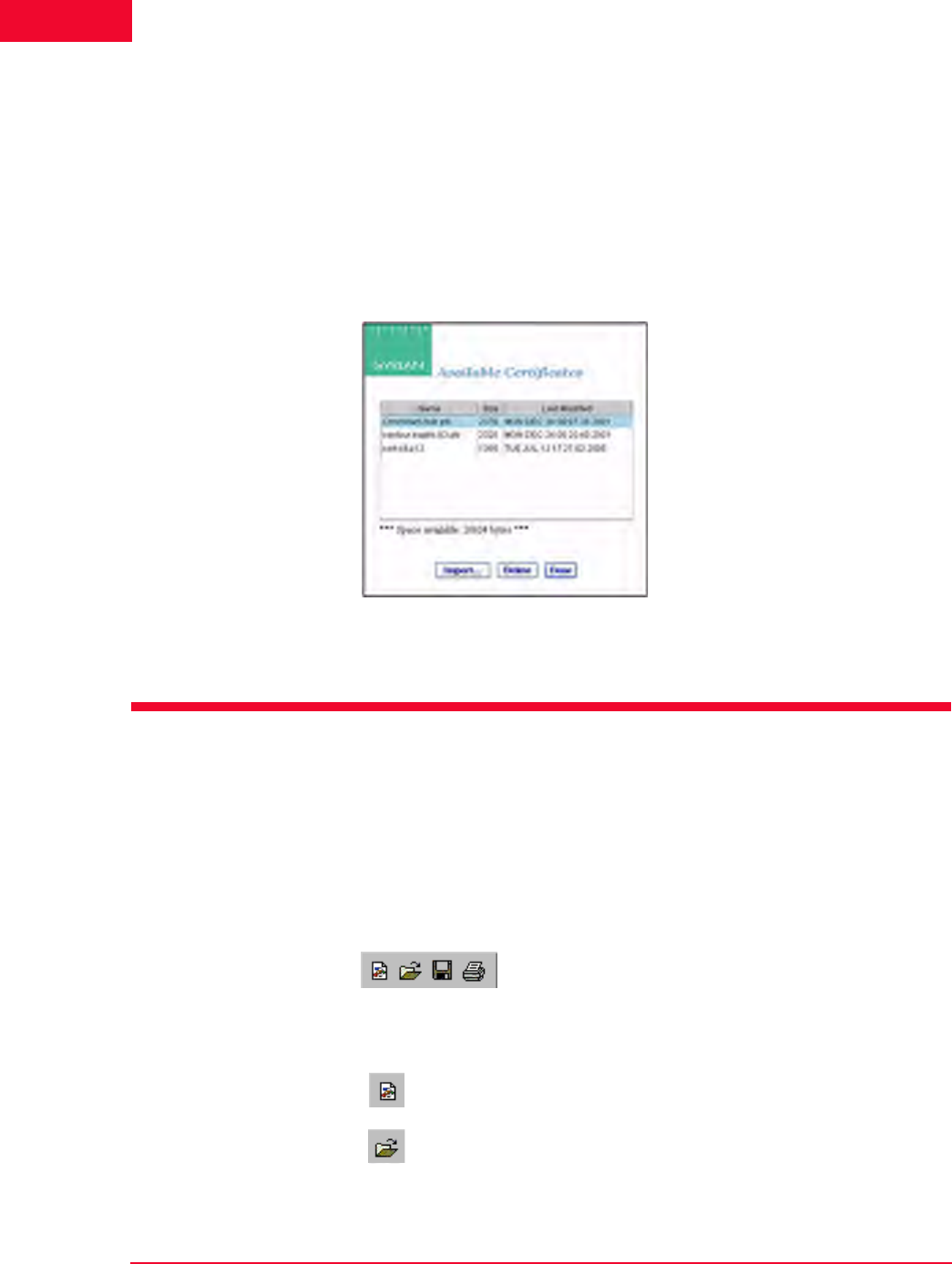
The Web-Based User Interface
Menus and Tool Bars
4-78 IxWLAN User Guide, Release 6.20
4
Show Welcome Screen on Startup: Click the checkbox to enable/disable the wel-
come screen that is shown when you successfully log on to the web-based user
interface.
•Click OK to close this page and save the configuration.
•Click Cancel to close this dialog without saving this configuration.
Configuration-
>Available
Certificates
The Available Certificates button in the Configuration side bar opens the Avail-
able Certificates dialog, as shown in Figure 4-94.
Figure 4-94. Available Certificates
For more information about Available Certificates, please refer to Available
Certificates on page 4-75.
Menus and Tool Bars
The menus and tool bars at the top of the web-based user interface can be used to
run tests, manipulate virtual stations, monitor results, and configure IxWLAN
and general scenario management.
File Tool Bar The buttons in this tool bar are used to create, open, save, and print scenarios
(Figure 4-95).
Figure 4-95. File Tool Bar
New Scenario: Creates a new scenario.
Open Scenario: Opens an existing scenario.
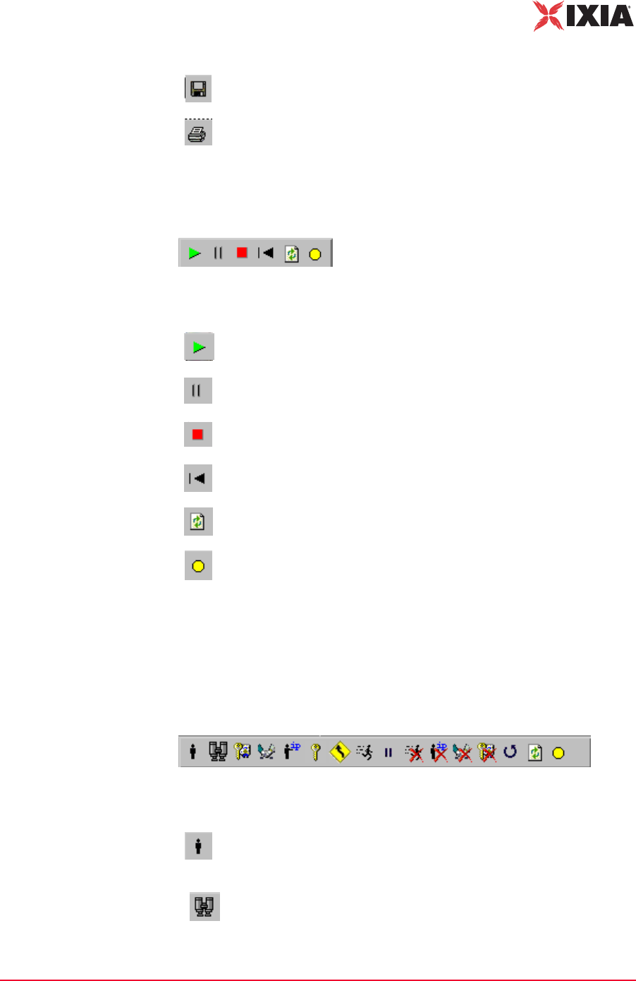
IxWLAN User Guide, Release 6.20 4-79
The Web-Based User Interface
Menus and Tool Bars
Scenario Tool Bar The buttons in this section of the tool bar can be used to run, pause, stop, restart,
or refresh the entire scenario of all virtual stations (Figure 4-96).
Figure 4-96. Scenario Tool Bar
vSTA Tool Bar The buttons in this tool bar are used to run, pause, stop, restart, or refresh selected
virtual stations or groups of virtual stations. The selected action is executed for
the group(s) and/or virtual station(s) that are selected/highlighted in the group
control grid (Figure 4-97).
Figure 4-97. vSTA Tool Bar
Save Scenario: Saves the current scenario.
Print: Prints the scenario configuration.
Run Scenario: Runs the test for all groups and all virtual stations in a
scenario.
Pause Scenario: Pauses the test for all groups and all virtual stations
in a scenario.
Terminate Scenario: Stops the test for all groups and all virtual
stations in a scenario.
Reset Scenario: Resets the test for all groups and all virtual stations in
a scenario.
Refresh Scenario: Refreshes the test for all groups and all virtual
stations in a scenario.
Quiesce: This selection causes the scenario (that is, all virtual
stations) to gracefully stop. The vSTA completes any currently active
iteration, then stops. A quiesced vSTA must be reset before it can run
again.
Initialize: Starts the currently selected groups or virtual stations.
Probe: Submits a probe request and waits for a probe response.

The Web-Based User Interface
Menus and Tool Bars
4-80 IxWLAN User Guide, Release 6.20
4
Authenticate: Causes the currently selected virtual stations or all
virtual stations in a group to initiate the 802.11 authentication sequence
with the System Under Test.
Associate: Causes the currently selected virtual stations or all virtual
stations in a group to initiate the 802.11 association sequence with the
System Under Test. The 802.11 association sequence automatically
transits through any necessary 802.1X authentication and key
management if the virtual station is configured for RSN, RSN-PSK,
WPA, or WPA-PSK.
Acquire IP: Causes the currently selected virtual stations to initiate a
request for an IP address using DHCP. This option is available only for
vSTAs created with the IP Generation Method of DHCP.
Pre-authenticate selected vSTA: Starts RSN (802.11i) pre-
authentication by a vSTA with a selectable remote AP. This is valid
only for stations configured for full RSN authentication. The virtual
station(s) must be in the Ready or Running state.
Roam vSTAs: For the web-based user interface running on an
IxWLAN SED chassis, it starts a Roam by all virtual stations to a
selectable target AP. Each virtual station roams according to its
configured roam type attribute. The Roam may include issuance of a
Probe Request and optional 802.11 authentication.
For the web-based user interface running on an IxWLAN SED-MR+
chassis, it starts a Roam by the selected virtual stations or groups to a
selectable target AP.
Run: Runs a test for selected groups or virtual stations.
Pause: Pauses a test for selected groups or virtual stations.
Stop: Ends a test for selected groups or virtual stations.
Release IP: Causes the currently selected virtual stations to release
their IP address using DHCP. This option is available only for vSTAs
created with the IP Generation Method of DHCP.
Disassociate: Causes the currently selected virtual stations or all
virtual stations in a group to initiate the 802.11 disassociation
sequence with the System Under Test. This sequence also drops any
WPA/RSN security associations.
De-authenticate: Causes the currently selected virtual stations or all
virtual stations in a group to initiate the de-authentication sequence
with the System Under Test. This sequence also drops any WPA/RSN
security associations.
Reset: Resets a test for selected groups or virtual stations.
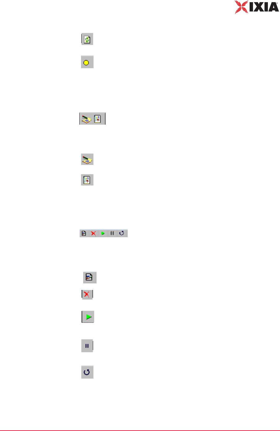
IxWLAN User Guide, Release 6.20 4-81
The Web-Based User Interface
Menus and Tool Bars
Reports Tool Bar The buttons in this tool bar are used to view the reports and event log (Figure 4-
98).
Figure 4-98. Reports Tool Bar
Monitor Tool Bar This tool bar is located in the top-right corner of the screen monitoring section.
The buttons in this tool bar can be used to control monitor(s) (Figure 4-99).
Figure 4-99. Monitor Tool Bar
Refresh: Refreshes a test for selected groups or virtual stations.
Quiesce: Causes the currently selected virtual stations to gracefully
end. The vSTA completes any currently active iteration, then stops. A
quiesced vSTA must be reset before it can run again.
View Reports: Opens the Generate Report dialog, where you can
select a report to display or export.
View Event Log: Shows the last 100 entries in the event log.
New Monitor: Allows you to define a new monitor.
Delete: Deletes a monitor. A dialog opens, asking you to confirm the
selection.
Run: Runs a monitor. When the Run Monitor button is selected, the
currently displayed monitor starts gathering and displaying its target
statistics.
Pause: Pauses a monitor. When the Pause Monitor button is
selected, the currently displayed monitor stops its target statistics.
However, statistics are accumulated in the background and can be
exported.
Clear: Clears a monitor. A dialog asks you to confirm the selection.
TBDThis selection set all counters in the current monitor be exported.
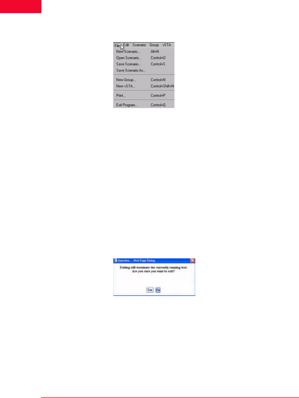
The Web-Based User Interface
Menus and Tool Bars
4-82 IxWLAN User Guide, Release 6.20
4
File Menu Figure 4-100 shows the File menu.
Figure 4-100.File Menu
New Scenario…: Creates a new scenario in which groups and virtual stations
can be defined.
Open Scenario…: Opens the Open Scenario dialog, where you can choose from
a list of existing scenario files on IxWLAN or browse your PC for scenario files.
Save Scenario…: Opens the Save Scenario dialog.
Save Scenario As…: Saves a scenario as a new instance.
New Group…: Opens the New IxWLAN Group dialog.
New vSTA…: Opens the Add vSTA to Group dialog.
Print: Sends the current scenario configuration to your printer.
Exit Program: Exits the web-based user interface. If a scenario is currently
active/running, the dialog shown in Figure 4-101 opens.
Figure 4-101.Exit Program

IxWLAN User Guide, Release 6.20 4-83
The Web-Based User Interface
Menus and Tool Bars
•Click Yes to continue by exiting the web-based user interface.
•Click No to return to the currently running test.
If the current scenario has been modified during this web-based user interface
session, the dialog shown in Figure 4-102 allows you to save these changes.
Figure 4-102.Save Scenario Modified
•Click Yes to open the Save Scenario dialog and save the scenario on your PC
or in the flash on the IxWLAN SED/SED-MR+ chassis.
•Click No if you do not want to save the modified scenario.
If active virtual stations have been configured, the dialog shown in Figure 4-103
asks you to save the results to flash.
Figure 4-103.Flash Save Dialog
•Click Yes to save the results of any active scenario(s) in the IxWLAN flash
file system.
•Click No to discard current test results.
The dialog shown in Figure 4-101 on page 4-82 asks you to confirm the exit from
the web-based user interface:
•Click Yes to exit.
•Click No to return to the web-based user interface.

The Web-Based User Interface
Menus and Tool Bars
4-84 IxWLAN User Guide, Release 6.20
4
Edit Menu Figure 4-104 shows the Edit menu.
Figure 4-104.Edit Menu
Select All: If a group tab is selected, selects all virtual stations in a scenario
group. If the Group Control tab opens, selects all groups.
Unselect All: If a group tab is selected, unselects all virtual stations in a scenario
group. If the Group Control tab opens, unselects all groups.
Cut: Removes the definition of the currently selected virtual station and places it
in the clipboard.
Copy: Copies a virtual station definition to clipboard.
Paste: Pastes the virtual station definition in the clipboard to the currently
selected group.
Delete: If a group tab is selected, deletes the currently selected virtual station. If
the Group Control tab opens, deletes the currently selected group.
Scenario Menu After you have defined a scenario, use the Scenario Menu to start and exercise
the scenario.
Figure 4-105 shows the Scenario menu.
Figure 4-105.Scenario Menu
Initialize: Starts all virtual stations defined in the scenario.
Probe: A Probe Request is sent by all virtual stations in the currently selected
group.
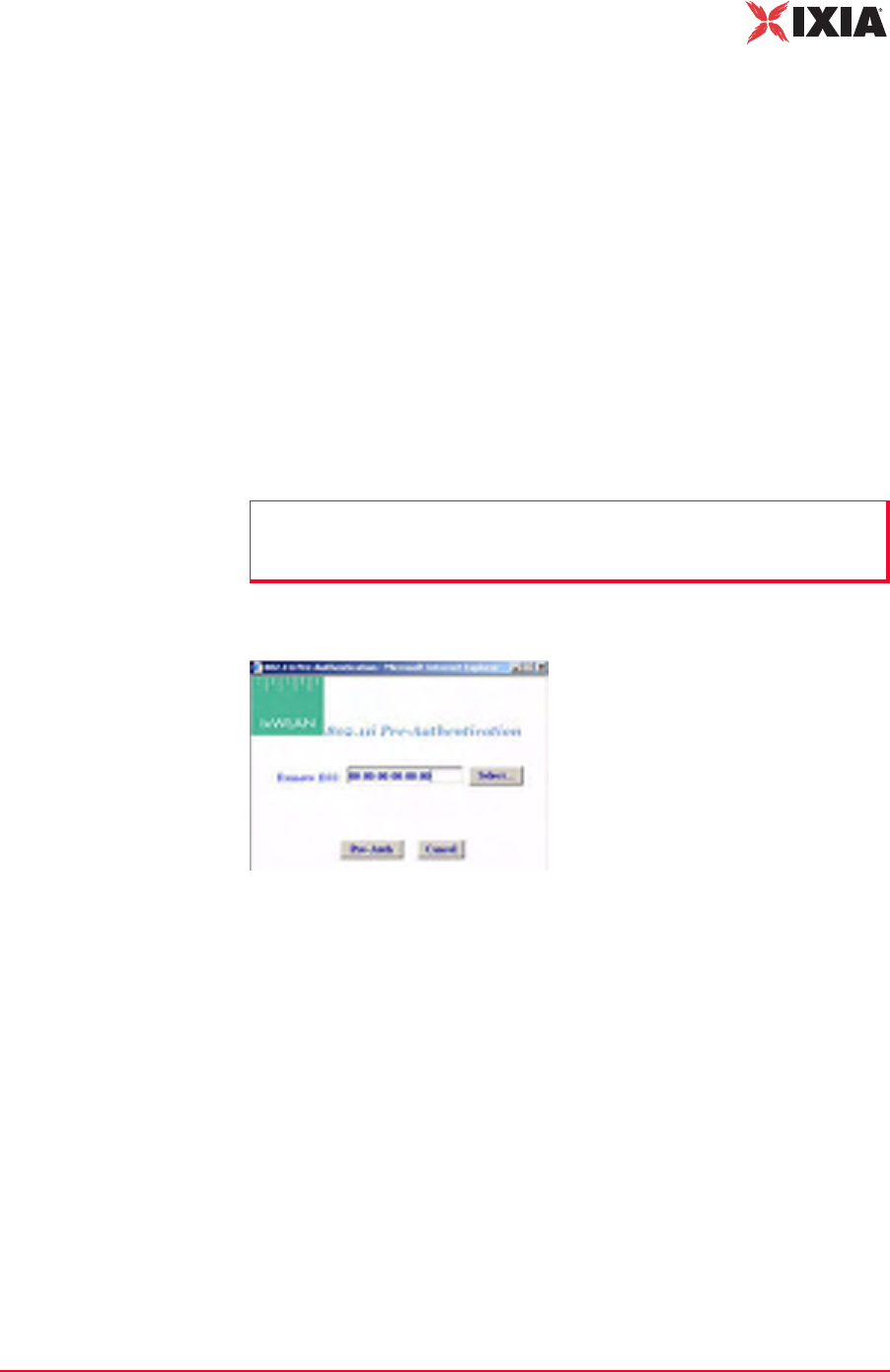
IxWLAN User Guide, Release 6.20 4-85
The Web-Based User Interface
Menus and Tool Bars
Authenticate: If clicked, all virtual stations defined in a scenario initiate the
802.11 authentication sequence to the System Under Test.
Associate: If clicked, all virtual stations defined in a scenario initiate the 802.11
association sequence to the System Under Test. The 802.11 association sequence
automatically transits through any necessary 802.1X authentication and key man-
agement if the virtual station is configured for RSN, RSN-PSK, WPA, or WPA-
PSK.
Acquire IP: Causes all virtual stations in the scenario to initiate a request for an
IP address using DHCP. This option is available only for vSTAs created with the
IP Generation Method of DHCP.
Pre-Authenticate: Starts RSN (802.11i) pre-authentication by a vSTA with a
selectable remote AP. This is valid only for stations configured for full RSN
authentication. The virtual station(s) must be in the Ready or Running state.
When Pre-Authenticate is selected, a dialog opens, as shown in Figure 4-106.
Figure 4-106.Pre-Authentication Dialog
Click the Select button to select a BSS from a list or to manually type a BSSID,
as shown in Figure 4-107 on page 4-86.
NOTE: Only one pre-authentication session per vSTA can be in progress at a
time. If the user initiates a second pre-authentication while another one is in
progress, an error message opens and logs in the event log
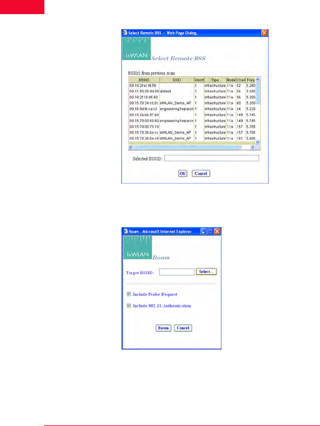
The Web-Based User Interface
Menus and Tool Bars
4-86 IxWLAN User Guide, Release 6.20
4
Figure 4-107.Select Remote BSS
Roam: Opens the Roam dialog, as shown in Figure 4-108. This command
applies to all currently selected vSTAs in the Group or wport tabs.
Figure 4-108.Roam Dialog
Click the Select button to select a BSS from a list or to manually type a BSSID,
as shown in Figure 4-107.
The two checkboxes select the Probe on Roam and Authenticate on Roam
options.

IxWLAN User Guide, Release 6.20 4-87
The Web-Based User Interface
Menus and Tool Bars
•Include Probe Request – Selects whether to issue a Probe Request during the
Roam.When enabled, a Probe Request is issued (and a Probe Response
expected) by each roaming virtual station during the Roam just before the
802.11 Authentication stage. When disabled, no Probe Request is sent.
•Include 802.11 Authentication – Selects whether to perform basic 802.11
Authentication during the Roam. When enabled, each roaming vSTA issues
an Authentication Request to the target AP during a Roam and it expects an
Authentication Response. When disabled, the 802.11 Authentication is
skipped during a Roam and the vSTA proceeds to the (Re)Association
exchange.
Run: Starts the execution of the test defined by this scenario.
Pause: Pauses the test and temporarily halts all virtual stations defined in the sce-
nario. Virtual stations may be restarted by selecting the Run option. This option
is dimmed (cannot be selected) if the scenario is not running.
Terminate: Stops a test and halts all virtual stations defined in the scenario. Vir-
tual stations must be reset before they can be run again. This option is dimmed
(cannot be selected) if the scenario is not running.
Reset: Resets all virtual stations in the scenario to a started state. Statistics for the
virtual stations are reset to zero. This option can be used to restart any virtual sta-
tions that may have encountered problems during a test.
Quiesce: This selection causes the scenario (that is, all virtual stations) to grace-
fully stop. The vSTA completes any currently active iteration, then stops. A qui-
esced vSTA must be reset before it can run again.
Group Menu After you have defined a group in a scenario, use the options in the Group menu
to edit and control any/all selected group(s).
Figure 4-109 shows the Group menu.
Figure 4-109.Group Menu
Edit Group: This selection opens the Edit IxWLAN Group dialog.

The Web-Based User Interface
Menus and Tool Bars
4-88 IxWLAN User Guide, Release 6.20
4
Initialize: Starts all virtual stations defined in the currently selected group.
Probe: A Probe Request is sent by all virtual stations in the currently selected
group. When invoked from the tool bar, probing does not change the Run State.
Authenticate: If clicked, all virtual stations in the currently selected group ini-
tiate the 802.11 authentication sequence to the System Under Test.
Associate: If clicked, all virtual stations in the currently selected group initiate
the 802.11 association sequence to the System Under Test. The 802.11 associa-
tion sequence automatically transits through any necessary 802.1X authentica-
tion and key management if the virtual station is configured for RSN, RSN-PSK,
WPA, or WPA-PSK.
Acquire IP: Causes all virtual stations in the group to initiate a request for an IP
address using DHCP. This option is available only for vSTAs created with the IP
Generation Method of DHCP.
Pre-Authenticate: This command is similar to that described in the Scenario
Menu section. For further information, please refer to Scenario Menu on page 4-
84.
Roam: This command is similar to that described in the Scenario Menu section.
For more information, please refer to Scenario Menu on page 4-84.
Run: Starts execution of all virtual stations defined in the currently selected
group(s).
Pause: Pauses execution of all virtual stations defined in the currently selected
group(s). This option is dimmed (cannot be selected) if the group is not running a
test.
Terminate: Stops all virtual stations defined in the currently selected group(s).
This option is dimmed (cannot be selected) if the group is not running a test.
Reset: Resets all virtual stations defined in the currently selected group(s).
Quiesce: Causes all virtual stations in the selected group to gracefully stop. The
vSTA completes any currently active iteration, then stops. A quiesced vSTA
must be reset before it can run again.

IxWLAN User Guide, Release 6.20 4-89
The Web-Based User Interface
Menus and Tool Bars
vSTA Menu Figure 4-110 shows the vSTA menu.
Figure 4-110.vSTA Menu
Edit vSTA…: Opens the virtual station configuration dialog.
Initialize: Starts the currently selected virtual station(s).
Probe: A Probe Request is sent by all virtual stations in the currently selected
group.
Authenticate: If clicked, the currently selected virtual station(s) start(s) the
802.11 authentication sequence to the System Under Test.
Associate: If clicked, the currently selected virtual station(s) start(s) the 802.11
association sequence to the System Under Test. The 802.11 association sequence
automatically transits through any necessary 802.1X authentication and key man-
agement if the virtual station is configured for RSN, RSN-PSK, WPA, or WPA-
PSK.
Acquire IP: Causes the currently selected virtual stations to initiate a request for
an IP address using DHCP. This option is available only for vSTAs created with
the IP Generation Method of DHCP.
Pre-Authenticate: This command is similar to that described in the Scenario
Menu section. For further information, please refer to Scenario Menu on page 4-
84.
Roam: This command is similar to that described in the Scenario Menu section.
For further information, please refer to Scenario Menu on page 4-84.
Run: Starts the execution of the currently selected virtual station(s).
Pause: Pauses the execution of the currently selected virtual station(s). This
option is dimmed (cannot be selected) if the virtual station is not running a test.
Terminate: Stops the currently selected virtual station(s). This option is dimmed
(cannot be selected) if the virtual station is not running a test.

The Web-Based User Interface
Menus and Tool Bars
4-90 IxWLAN User Guide, Release 6.20
4
Reset: Resets the currently selected virtual station(s).
Quiesce: This selection causes the currently selected virtual stations to gracefully
stop. The vSTA completes any currently active iteration, then stops. A quiesced
vSTA must be reset before it can run again.
Reports Menu Figure 4-111 shows the Reports menu.
Figure 4-111. Reports Menu
IxWLAN Configuration…: Shows the IxWLAN configuration report.
Scenario Summary…: Shows the scenario summary statistics report.
Group Summary…: Shows the group summary statistics report.
vSTA Master…: Shows the virtual station master (that is, IxWLAN) statistics
report.
vSTA Detailed…: Shows the virtual station detailed statistics report.
Export Report…: Opens the Generate Report dialog.
View Logfile…: Shows the event log.
Export Logfile: Opens the Export Logfile dialog.

IxWLAN User Guide, Release 6.20 4-91
The Web-Based User Interface
Menus and Tool Bars
Options Menu Figure 4-112 shows the Options menu.
Figure 4-112.Options Menu
Configure IxWLAN…: Opens the Configure IxWLAN dialog.
Configure Monitors…: Opens the Configure Monitoring dialog.
Configure Ping…: Opens the Configure Ping dialog.
Configure Security…: Opens the Security Configuration dialog.
Configure Event Log…: Opens the Configure Event Log dialog.
Configure UI…: Opens the UI (User Interface) Configuration dialog.
Configure Table View…: Opens the Table Configuration dialog for group tab
columns.
Configure Available Certificates…: Opens the Available Certificates dialog.
About Menu Figure 4-112 shows the About menu.
Figure 4-113.About Menu
About IxWLAN…: Shows the IxWLAN current version number.
Update IxWLAN…: Opens the Update IxWLAN dialog.
About Ixia…: Accesses the Ixia Web site.

The Web-Based User Interface
Menus and Tool Bars
4-92 IxWLAN User Guide, Release 6.20
4

IxWLAN User Guide, Release 6.20 5-1
5Chapter 5: The Command Line
Interface (CLI)
This chapter covers the following topics:
•CLI Usage Notes on page 5-3.
•User Login on page 5-3.
•User Logoff on page 5-4.
•CLI Commands on page 5-4.
•System Under Test Commands on page 5-7.
•Virtual Station Setup and Control Commands on page 5-14.
•Statistics File Commands on page 5-51.
•Event Log Commands on page 5-53.
•IxWLAN Commands on page 5-58.
•802.11b/g Commands on page 5-86.
•Administrative Mode Commands on page 5-90.
•Example Configurations on page 5-97.
•CLI Editor on page 5-114.
The CLI can be used to show and modify the configuration of IxWLAN from a
PC that is connected via Telnet or the serial port. The CLI also includes com-
mands to configure and run virtual stations, show statistics, and access the Sys-
tem Under Test. IxWLAN maintains statistics and event log files that you can
configure and display using CLI commands. Some of these commands apply to
all wports, while other are wport-specific. The following commands are wport-
specific:
•bsslist (get) on page 5-9.
•join on page 5-10.
•hwtxretries (get/set) on page 5-94.
•scan on page 5-11.
•get association on page 5-65.

The Command Line Interface (CLI)
5-2 IxWLAN User Guide, Release 6.20
5
•get basic11g (11g only) on page 5-91.
•set basic11g (11g only) on page 5-92.
•get basic11b (11b only) on page 5-87.
•set basic11b (11b only) on page 5-87.
•get bssid on page 5-8.
•set bssid on page 5-8.
•clear bssid on page 5-8.
•get channel on page 5-66.
•get ctsmode (11g only) on page 5-87.
•set ctsmode (11g only) on page 5-87.
•get ctsrate (11g only) on page 5-88.
•set ctsrate (11g only) on page 5-88.
•get ctstype (11g only) on page 5-88.
•set ctstype (11g only) on page 5-88.
•get frequency on page 5-69.
•get key on page 5-70.
•set key on page 5-80.
•get pmmode on page 5-71.
•set pmmode on page 5-81.
•get power on page 5-71.
•set power on page 5-82.
•get psinterval on page 5-71.
•set psinterval on page 5-83.
•get rate on page 5-72.
•set rate on page 5-83.
•get shortpreamble (11b/11g) on page 5-89.
•set shortpreamble (11b/11g) on page 5-89.
•get shortslottime (11g only) on page 5-89.
•set shortslottime (11g only) on page 5-89.
•get ssid on page 5-13.
•set ssid on page 5-13.
•get station on page 5-72.
•get wirelessmode on page 5-73.
•set wirelessmode on page 5-85.
•get wlanmac on page 5-73.

IxWLAN User Guide, Release 6.20 5-3
The Command Line Interface (CLI)
CLI Usage Notes
•set wlanmac on page 5-85.
•reset wlanmac on page 5-77.
CLI Usage Notes
1. CLI commands are not case sensitive (for example, set Date is the same as
set date).
2. You do not need to type the entire command string to execute a command.
Only the number of unique characters needed to identify the command are
needed (for example, se da executes the set date command because there are
no other CLI commands that begin with se and no other set objects that begin
with da).
3. Some parameters can be assigned very large values in the 0 to 2,147,483,647
range. Do not type commas (,) for values larger than 999 (for example, use
1000 rather than 1,000).
4. It is very important to keep a printed record of configuration parameters. See
Configuration Records on page 8-14.
User Login
The IxWLAN logon prompt displays after you successfully establish a connec-
tion to IxWLAN. See Chapter 3, First Setup. After you have successfully estab-
lished this connection, the CLI prompts you to type a logon name and password.
IxWLAN login: Admin
Password: ******
The default logon user name is Admin. The default password is IxWLAN. Both
entries are case-sensitive (that is, the default user name is Admin, not admin).
After you type a valid user name and password, the CLI displays a version ban-
ner, the current system time and status, and a CLI prompt (IxWLAN ->).
Ixia IxWLAN(tm) Rev 6.20.0.129 EB
System date & time: FRI APR 20 10:03:31 2007
Use the "set date" or "set time" command to adjust
IxWLAN(tm) software version 6.20.0.129 EB
Number of wports present ....... 3
Multi-radio mode ............... Static
Mgmt LAN MAC address ........... 00:08:9b:68:2c:81
Data LAN MAC address ........... 00:08:9b:68:2c:82
MIC check ...................... Enabled
Crypto hardware ................ OK
0 vSTAs currently in the system.
[wport1]IxWLAN ->
The CLI is now ready to accept your commands.

The Command Line Interface (CLI)
User Logoff
5-4 IxWLAN User Guide, Release 6.20
5
User Logoff
Use the quit command to log off from the CLI.
IxWLAN -> quit
After logoff, you must re-establish the telnet connection to log on to the CLI.
CLI Commands
The help command shows a list of all CLI commands.
Example:
[wport1]IxWLAN -> help
List of IxWLAN CLI commands:
acquireip -- Acquire an IP address for a vSTA
assoc -- Associate a vSTA with the SUT
auth -- Authenticate a vSTA with the SUT
autoconf -- Autoconfig-init-auth-assoc N vSTAs
autorun -- Run N configured/associated vSTAs
clear bssid -- Clear BSSID for System Under Test
clear evlog -- Clear event log file or buffer
clear group -- Clear vSTA group data
clear sntpserver -- Clear SNTP/NTP server IP address
clear systemname -- Clear the IxWLAN system name
clear vsta -- Clear vSTA data
conf -- Configure a vSTA
cryptotest -- Crypto hardware self-test
deauth -- Deauthenticate a vSTA
del group -- Delete a vSTA group
del key -- Delete Encryption key
del statfile -- Delete a vSTA statistics file
del summfile -- Delete a vSTA statistics summary file
del vsta -- Delete a vSTA
disassoc -- Disassociate a vSTA
exec -- Execute a command file
ftp -- Software update via FTP
get association -- Display Association Table
get basic11b -- Display Basic 11b Rates
get bootscan -- Display Boot Scan Mode
get bkjoin -- Display Background Join
get bssid -- Display BSSID of System Under Test
get bsslist -- Display list of discovered BSSIDs
get channel -- Display Radio Channel
get config -- Display current IxWLAN configuration
get countrycode -- Display Country Code
get cryptocap -- Display crypto hardware capabilities
get evlog -- Display event log data
get features -- Display authorized features
NOTE: If the CLI shows the “This IxWLAN has not been Node Locked”
message after you type the IxWLAN logon name and password, see Missing
Key File on page 8-7.

IxWLAN User Guide, Release 6.20 5-5
The Command Line Interface (CLI)
CLI Commands
get frequency -- Display Radio Frequency (MHz)
get gateway -- Display Gateway IP Address
get group -- Display information for a vSTA group
get hardware -- Display Hardware Revisions
get ipaddr -- Display IP Address
get ipmask -- Display IP Subnet Mask
get key -- Display Encryption Key
get keyentrymethod -- Display Encryption Key Entry Method
get login -- Display Login User Name
get mic -- Display Software MIC Control
get multiradiomode -- Display multi-radio mode
get pmmode -- Display Power Management Mode
get power -- Display Transmit Power Setting
get psinterval -- Display Power Save Listen Interval
get rate -- Display Data Rate
get sntpserver -- Display SNTP/NTP Server IP Address
get ssid -- Display Service Set ID
get statfile -- Display vSTA statistics from file
get station -- Display Station Status
get status -- Display IxWLAN status
get summfile -- Display vSTA statistics summary from file
get systemname -- Display the IxWLAN system name
get telnet -- Display Telnet Mode
get tzone -- Display Time Zone Setting
get uptime -- Display UpTime
get version -- Display Firmware Version
get vsta -- Display vSTA information
get wirelessmode -- Display Wireless LAN Mode
get wlanmac -- Display Wireless LAN MAC Address
get wlanmask -- Display Wireless LAN Address Mask
get wport -- Display wport information
halt -- Halt a running vSTA
help -- Display CLI Command List
history -- Display the command line history
import -- Import PKCS#12 certfile via FTP
init -- Initialize a configured vSTA
join -- Join the IxWLAN with the System Under Test
ping -- Ping
preauth -- Pre-authenticate a vSTA with a remote AP
quit -- Logoff
reboot -- Reboot the IxWLAN
releaseip -- Release a vSTA's IP address
reset group -- Reset a vSTA group to the initialized state
reset vsta -- Reset a vSTA to the initialized state
reset wlanmac -- Reset the WLAN MAC address to default value
roam -- Roam a vSTA to target BSS
run -- Run an associated vSTA
save evlog -- Save the event log buffer to file
save group -- Save vSTA group data
save vsta -- Save vSTA data
scan -- Acquire SUT (scan/join)
sendprobe -- Send probe request from vSTA
set bkjoin -- Set Background Join
set bootscan -- Set Bootscan mode
set bssid -- Set the BSSID for the System Under Test
set countrycode -- Set Country Code
set date -- Set the system date

The Command Line Interface (CLI)
CLI Commands
5-6 IxWLAN User Guide, Release 6.20
5
set evlog -- Set event log controls
set factorydefault -- Restore to Default Factory Settings
set features -- Upgrade current feature set
set gateway -- Set Gateway IP Address
set group -- Set vSTA group configuration parameters
set ipaddr -- Set IP Address
set ipmask -- Set IP Subnet Mask
set key -- Set Encryption Key
set keyentrymethod -- Select Encryption Key Entry Method
set login -- Modify Login User Name
set mic -- Set Software MIC Control
set multiradiomode -- Set multi-radio mode
set password -- Modify Password
set pmmode -- Set Power Management Mode
set power -- Set Transmit Power
set psinterval -- Set Power Save Listen Interval
set rate -- Set Data Rate
set sntpserver -- Set SNTP/NTP Server IP Address
set ssid -- Set Service Set ID
set systemname -- Set the IxWLAN system name
set telnet -- Set Telnet Mode
set time -- Set the system time
set tzone -- Set Time Zone Setting
set vsta -- Set vSTA configuration parameters
set wirelessmode -- Set Wireless LAN Mode
set wlanmac -- Set WLAN MAC Address
set wlanmask -- Set WLAN Address Mask
set wport -- Set wport for configuration
timeofday -- Display Current Time of Day
version -- Software version
[wport1]IxWLAN ->
This list does not include the commands that are available in the administrative
mode. See Administrative Mode Commands on page 5-90 for a list including
more commands that are available in the administrative mode. Also, the list of
commands is slightly different depending on the wireless mode. If the wireless
mode is 802.11a, for example, the list does not include commands that are spe-
cific to 802.11g.
NOTE: The trace command is available both in the user and admin mode. In
the user mode, it is not listed among the other commands in the help output. For
details about this command, see Administrative Mode Commands on page 5-90
or trace on page 5-95.

IxWLAN User Guide, Release 6.20 5-7
The Command Line Interface (CLI)
System Under Test Commands
System Under Test Commands
These commands are used to scan for and join with a device that can be tested by
IxWLAN. These commands must be used to select and join with a System Under
Test before you can use the following Virtual Station Set-Up and Control Com-
mands.
clear bssid -- Clear BSSID for System Under Test
get bssid -- Display BSSID of System Under Test
get bsslist -- Display list of discovered BSSIDs
get ssid -- Display Service Set ID
get wirelessmode -- Display Wireless LAN Mode
join -- Join the IxWLAN with the System Under Test
scan -- Acquire SUT (scan/join)
set bssid -- Set the BSSID for the System Under Test
set ssid -- Set Service Set ID
set wirelessmode -- Set Wireless LAN Mode
These commands also allow you to change the System Under Test while virtual
stations are defined and active. Use the following command sequence:
1. Use the reset command to return all virtual stations to an initialized state:
reset vsta all
2. If the new System Under Test is not in IxWLAN's BSS list, a scan is needed:
scan
3. Use the set bssid command to set IxWLAN to another System Under Test:
set bssid <mac_address_of_new_SUT>
4. Use the join command to join with the System Under Test:
join
5. If virtual stations are configured for WPA or RSN authentication and the new
System Under Test has a different passphrase, change the passphrase for all
virtual stations to match the new System Under Test:
set vsta all passphrase <SUTs_passphrase>
6. Issue the authenticate command for all virtual stations:
auth vsta all
7. Issue the associate command for all virtual stations:
assoc vsta all
8. Run the test for all virtual stations:
run vsta all
This section covers the following commands:
•bssid (get/set/clear) on page 5-8
•bsslist (get) on page 5-9

The Command Line Interface (CLI)
System Under Test Commands
5-8 IxWLAN User Guide, Release 6.20
5
•join on page 5-10
•scan on page 5-11
•ssid (get/set) on page 5-13
bssid (get/set/clear) get bssid
Shows the current BSSID/MAC address of the system being tested.
get bssid
Example:
[wport1]IxWLAN -> get bssid
BSSID of System Under Test: 00:04:e2:34:e0:a8
[wport1]IxWLAN ->
set bssid
Specifies the BSSID/MAC address of the system to be tested. This is the System
Under Test that IxWLAN scans for and joins with. The default value is all zeros.
set bssid <mac_address>
<mac_address>: MAC address of the System Under Test.
Example:
[wport1]IxWLAN -> set bssid 00:04:e2:34:e0:a8
BSSID of System Under Test: 00:04:e2:34:e0:a8
IxWLAN ->
IxWLAN -> get bssid
BSSID of System Under Test: 00:04:e2:34:e0:a8
[wport1]IxWLAN ->
clear bssid
Clears the current BSSID.
clear bssid
Example:
[wport1]IxWLAN -> clear bssid
BSSID 00:04:e2:34:e0:a8 cleared
use the set bssid CLI command to set the BSSID of the
System Under Test
[wport1]IxWLAN ->
NOTE: IxWLAN must be configured with a non-zero BSSID to perform a Join
operation and to create and run virtual stations.

IxWLAN User Guide, Release 6.20 5-9
The Command Line Interface (CLI)
System Under Test Commands
bsslist (get) Shows the Basic Service Sets discovered in the most recent scan. See scan on
page 5-11.
get bsslist [detail]
Use the [detail] option to view detailed information regarding each BSS’s rate
capabilities and needs, country code and channel capabilities, and security infor-
mation.
Example for get bsslist:
[wport1]IxWLAN -> get bsslist
Use "get bsslist detail" for additional info
Type Chan Sec RSSI BSSID SSID
---- ---- --- ---- ----- ----
AP 44 38 00:05:4e:41:3c:19 QA_A_AP
AP 60 WEP 61 00:04:e2:37:e6:a1 CK S-1
AP 64 TKIP 53 00:0b:6b:30:05:6c cb/wpa
AP 149 TKIP 39 00:12:d9:c4:0a:90 s TKIP
AP SUT 157 AES 51 00:0b:6b:30:05:65 CK D-1
AP 165 52 00:0b:6b:30:05:86 cb/ap1
AP: 6, Ad-Hoc: 0, Total BSSs: 6
[wport1]IxWLAN ->
Type: The Type column indicates the type of BSS detected: AP=Infrastructure
BSS, <Type> SUT=System Under Test, Ad-Hoc=Ad-Hoc BSS.
Chan: BSS channel number. The BSS list is sorted in channel number order.
Sec: Brief description of the security level of the BSS. If multiple security fea-
tures are active, this column shows the highest level of security. Use the [detail]
option to show all security options in effect.
RSSI: The RSSI column shows the relative received signal strength indicator for
the BSS. A higher RSSI value indicates that a stronger signal is received.
BSSID: The BSSID column shows the BSS identifier.
SSID: The SSID column shows the service set identifier for the BSS discovered
via a probe request.
Example for get bsslist detail:
[wport1]IxWLAN -> get bsslist detail
BSS Type Channel RSSI BSSID SSID
-------- ------- ---- ----- ----
AP BSS 5.220 ( 44) 38 00:05:4e:41:3c:19 QA_A_AP
Rates: *6, 9, *12, 18, *24, 36, 48, 54
AP BSS 5.300 ( 60) 61 00:04:e2:37:e6:a1 CK S-1
Rates: *6, 9, *12, 18, *24, 36, 48, 54
Security: WEP
AP BSS 5.320 ( 64) 53 00:0b:6b:30:05:6c cb/wpa
Rates: *6, 9, *12, 18, *24, 36, 48, 54
Security: WPA/EAP/TKIP

The Command Line Interface (CLI)
System Under Test Commands
5-10 IxWLAN User Guide, Release 6.20
5
Country: US [ 52 (5260) 4 23] [ 36 (5180) 4 17] [149 (5745) 5 30]
AP BSS 5.745 (149) 39 00:12:d9:c4:0a:90 s TKIP
Rates: *6, *9, *12, *18, *24, *36, *48, *54
Security: WPA/PSK/TKIP
AP BSS 5.785 (157) 51 00:0b:6b:30:05:65 CK D-1
* * This is the System Under Test * *
Rates: *6, 9, *12, 18, *24, 36, 48, 54
Security: RSN/PSK/AES/TKIP
Country: US [ 52 (5260) 4 23] [ 36 (5180) 4 17] [149 (5745) 5 30]
AP BSS 5.825 (165) 52 00:0b:6b:30:05:86 cb/ap1
Rates: *6, 9, *12, 18, *24, 36, 48, 54
Country: US [ 52 (5260) 4 23] [ 36 (5180) 4 17] [149 (5745) 5 30]
AP: 6, Ad-Hoc: 0, Total BSSs: 6
The get bsslist detail command shows detailed information regarding the rate
capabilities and needs, country code and channel capabilities, and security infor-
mation of each BSS. This information is presented as it is read from the BSS’s
Beacon or Probe Response, when present. Not all APs broadcast this detail infor-
mation. It is shown only when available.
The first line of each BSS detail line item shows the basic BSS information: type,
channel, RSSI, BSSID, and SSID. The * * This is the System Under Test * *
message displays after the basic BSS information line if the System Under Test is
specified and detected.
Rates: This line indicates the set of transmit rates supported in the BSS. Entries
marked by an asterisk (for example, *6, *24) indicate a member of the BSS’s
basic rate set.
Security: This line indicates all security information that can be determined pas-
sively through inspection of information found in the Beacon or Probe Response.
WEP indicates basic WEP encryption. WPA or RSN indicate higher security in
the form of advanced authentication and encryption algorithms. PSK indicates
Pre-Shared Key authentication. EAP indicates the use of a more robust EAP-
based authentication algorithm. TKIP and AES indicate the cipher algorithm in
use. A WPA or RSN BSS may support more than one authentication or cipher
suite.
Country: This line indicates information found in the Country information ele-
ment, when present. This includes the country code and the channel list. The
channel list is formatted in the form: [first channel, number of channels, maxi-
mum transmit power]. Example: [ 52 (5260) 4 23]. In this example, first chan-
nel=52, number of channels =4, maximum transmit power=23.
join Joins with the System Under Test. It must be present in the current Basic Service
Set list. See bsslist (get) on page 5-9.
join
Example:
[wport1]IxWLAN -> join
The join should take about 1 sec
[wport1]IxWLAN -> IxWLAN: wport1 Join: Checking BSS ... OK

IxWLAN User Guide, Release 6.20 5-11
The Command Line Interface (CLI)
System Under Test Commands
IxWLAN: wport1 Join: Checking channel ... OK
IxWLAN: wport1 Join: Initiating JOIN ...
Infrastructure 5.260 29 00:0b:6b:30:05:9f ixia/dmm/atheros
IxWLAN: wport1 Join: channel 52 (5260 MHz), ixia/dmm/atheros
OK
wport1 NOTIFY Operation JOIN succeeded - FRI MAR 30 14:05:57 2007
[wport1]IxWLAN ->
Example:
[wport1]IxWLAN -> join
The join should take about 1 sec
[wport1]IxWLAN -> IxWLAN: wport1 Join: Checking BSS ... OK
IxWLAN: wport1 Join: Checking channel ... OK
IxWLAN: wport1 Join: Initiating JOIN ...
Infrastructure 5.240 58 00:0b:6b:30:05:86 AccessPoint_1
IxWLAN Join: channel 157 (5785 MHz), CK D-1
OK
[wport1]IxWLAN ->
vSTA 1 PSK: f769e4fdc6b97b780c7f3799c6d58ce7250ca3779930cb4d2545dacbc45092d1
[wport1]IxWLAN ->
wport1 NOTIFY Operation JOIN succeeded - MON MAY 09 10:42:30 2005
[wport1]IxWLAN ->
scan Scans for Basic Service Set IDs and optionally joins with the System Under Test.
The IxWLAN wireless mode affects the type of devices that can be detected in a
scan. To change the IxWLAN wireless mode, see Virtual Station Setup and
Control Commands on page 5-14.
[wport1]IxWLAN -> scan
Active (probe request) or passive (listen for beacons) [a/p:
p]?
Type a and press ENTER to select an active scan. Just press ENTER to select the
default passive mode. If the passive mode is selected, the CLI prompts for the
following scanning options:
Channel (0 = all, m=all modes) [0]?
Channel timeout in msec [300]?
If typing m for the channel, all valid channels in all valid modes are scanned.
The default entry of 0 selects all valid channels in the current wireless mode.
NOTE: If any virtual stations are configured for WPA-PSK or RSN-PSK
authentication using a passphrase and IxWLAN is already joined at the time a
join command selects a different SSID, the Pre-Shared Keys is regenerated for
every vSTA that has a passphrase set.
NOTE: If a test is in process (see get wirelessmode on page 5-73), a scan
operation is disruptive to the normal testing operations of IxWLAN.

The Command Line Interface (CLI)
System Under Test Commands
5-12 IxWLAN User Guide, Release 6.20
5
If the active mode is selected, the CLI prompts for the following scanning
options:
Broadcast or directed probe request [b/d: d]?
Channel (0 = all, m=all modes) [0]?
Channel timeout in msec [300]?
In response to the Channel prompt, you may type zero for all channels or any
valid 802.11a or 802.11b/g channel number or frequency. The range of channels/
frequencies depends on the wireless mode and the features that are enabled on
IxWLAN. See the specifications in Appendix A, Specifications for a list of valid
channel numbers and frequencies for 802.11a, 802.11b, and 802.11g.
The CLI prompts to join with a system (if any) found in the scan. If IxWLAN is
already joined with a System Under Test, the default response is y:
Attempt a join with SUT 00:04:e2:38:56:78 [y/n: y]?
If IxWLAN is not joined with a System Under Test, the default response is n:
Attempt a join with SUT 00:04:e2:38:56:78 [y/n: n]?
Type y or n and press ENTER or just press ENTER to select the default.
Example:
[wport1]IxWLAN -> scan
Active (probe request) or passive (listen for beacons) [a/p:p]?
Channel (0 = all) [0]?
Channel timeout in msec [300]?
Attempt a join with SUT 00:04:e2:38:a8:d2 [y/n: n]?
The scan should take about 4 sec
[wport1]IxWLAN -> OK
[wport1]IxWLAN ->
[wport1]IxWLAN ->
Passive scanning 5 GHz 54Mbps (802.11a) channels for 4 seconds...
Select BSS: Looking for .. 00:04:E2:38:A8:D2
Select BSS: Found ........ 00:04:E2:38:A8:D2
=> BSS'es from the selected wireless mode <=
BSS Type Channel RSSI BSSID SSID
-------- ------- ---- ----- ----
SUT BSS 5.220 ( 44) 31 00:04:e2:38:a7:87 AccessPoint_1
SUT BSS 5.260 ( 52) 55 00:04:e2:38:a8:d2 AccessPoint_2
SUT BSS 5.280 ( 56) 46 00:04:e2:38:56:68 AccessPoint_3
SUT BSS 5.300 ( 60) 44 00:04:e2:37:e6:a1 AccessPoint_4
SUT: 4, Ad-Hoc: 0. Total BSS: 4
wport1 NOTIFY Operation SCAN succeeded - FRI MAR 30 14:14:52 2007
wport1 NOTIFY Operation SCAN&JOIN succeeded - FRI MAR 30 14:14:52 2007
[wport1]IxWLAN -> scan
Active (probe request) or passive (listen for beacons) [a/p: p]? a
Broadcast or directed probe request [b/d: d]?

IxWLAN User Guide, Release 6.20 5-13
The Command Line Interface (CLI)
System Under Test Commands
Channel (0 = all) [0]? 2412
Channel timeout in msec [300]?
Attempt a join with SUT 00:04:e2:38:a8:d2 [y/n: n]?
The scan should take about 1 sec
[wport1]IxWLAN -> OK
[wport1]IxWLAN ->
[wport1]IxWLAN -> InitSingleScan -- 2412, a00 cck 2.4
Active scanning 2.4GHz 11Mbps (802.11b) channels for 1 seconds...
wlanMlmeProbeRequest -- channel 2412
Select BSS: Looking for .. 00:04:E2:38:A8:D2
Select BSS: Found ........ 00:04:E2:38:A8:D2
InitSingleScan -- 2412, a00 cck 2.4
Active scanning 2.4GHz 11Mbps (802.11b) channels for 1 seconds...
wlanMlmeProbeRequest -- channel 2412
wport1 NOTIFY Operation SCAN succeeded - FRI MAR 30 14:14:52 2007
wport1 NOTIFY Operation SCAN&JOIN succeeded - FRI MAR 30 14:14:52 2007
[wport1]IxWLAN ->
ssid (get/set) get ssid
Displays the IxWLAN global Service Set Identifier attribute.
[wport1]IxWLAN -> get ssid
SSID: IxWLAN Test Wireless Network
[wport1]IxWLAN ->
set ssid
Sets the given value to the IxWLAN global Service Set Identifier attribute.
To reset the global SSID to the factory default string, enter the following com-
mand: set ssid default.
[wport1]IxWLAN -> set ssid default
* *
* * DO NOT REMOVE POWER FROM THE IxWLAN UNIT!
* * Wait for the IxWLAN to update the configuration file in Flas
* * or use the "reboot" command for immediate update & reboot.
* * Automatic update will be done within one minute.
* *
[wport1]IxWLAN -> ...Configuration file update completed.
get ssid
SSID: IxWLAN Test Wireless Network

The Command Line Interface (CLI)
Virtual Station Setup and Control Commands
5-14 IxWLAN User Guide, Release 6.20
5
Virtual Station Setup and
Control Commands
The following commands configure and activate virtual stations.
acquireip -- Acquire an IP address for a vSTA
assoc -- Associate a vSTA with the SUT
auth -- Authenticate a vSTA with the SUT
autoconf -- Autoconfig-init-auth-assoc N vSTAs
autorun -- Run N configured/associated vSTAs
clear group -- Clear vSTA group data
clear vsta -- Clear vSTA data
conf -- Configure a vSTA
deauth -- Deauthenticate a vSTA
del group -- Delete a vSTA group
del vsta -- Delete a vSTA
disassoc -- Disassociate a vSTA
get group -- Display information for a vSTA group
get vsta -- Display vSTA information
halt -- Halt a running vSTA
preauth -- Pre-authenticate a vSTA with a remote AP
releaseip -- Release a vSTA's IP address
reset group -- Reset a vSTA group to the initialized state
reset vsta -- Reset a vSTA to the initialized state
roam -- Roam a vSTA to target BSS
run -- Run an associated vSTA
save evlog -- Save the event log buffer to file
save group -- Save vSTA group data
save vsta -- Save vSTA data
sendprobe -- Send probe request from vSTA
set group -- Set vSTA group configuration parameters
set vsta -- Set vSTA configuration parameters
Most of the commands in this group need that you join with a System Under
Test. If a join or scan has not been done, the CLI shows the following message:
**You must do a "join" or a "scan" with the join option first.
Use the described System Under Test commands to join with a System Under
Test before using the commands in this group.
NOTE: There is no need for an explicit Join when Background Join is enabled.

IxWLAN User Guide, Release 6.20 5-15
The Command Line Interface (CLI)
Virtual Station Setup and Control Commands
This section covers the following commands:
•acquireip on page 5-16.
•assoc on page 5-16.
•auth on page 5-17.
•autoconf on page 5-18.
•autorun on page 5-23.
•clear group on page 5-23.
•clear vsta on page 5-23.
•conf on page 5-24.
•deauth on page 5-26.
•del group on page 5-27.
•del vSTA on page 5-27.
•disassoc on page 5-27.
•get group on page 5-28.
•get vsta on page 5-30.
•halt on page 5-36.
•init on page 5-36.
•preauth on page 5-37.
•releaseip on page 5-37.
•reset group on page 5-38.
•reset vsta on page 5-38.
•roam on page 5-38.
•run on page 5-39.
•save group(stats/summary) on page 5-39.
•save vsta(stats/summary) on page 5-40.
•sendprobe on page 5-40.
•set group on page 5-42.
•set vsta on page 5-46.
NOTE: Most of the commands in this group need that you specify a virtual
station ID in the 1 to 64 range for the IxWLAN SED chassis, and in the 1 to 128
range for the IxWLAN SED-MR+. If you intend to configure all virtual stations for
WPA or RSN authentication, the maximum number of virtual stations is:
•59 for the IxWLAN SED chassis
•59 per wport—in the Static multi-radio mode—for the IxWLAN SED-MR+
chassis
•59—in the Dynamic multi-radio mode—for the IxWLAN SED-MR+ chassis

The Command Line Interface (CLI)
Virtual Station Setup and Control Commands
5-16 IxWLAN User Guide, Release 6.20
5
acquireip Starts the DHCP negotiation process for the specified virtual station(s). The vir-
tual station must be in the 802.11 Associated state or 802.1X authenticated if
security is turned on and the vSTA’s DHCP mode (dhcpmode) must be set to on.
See autoconf on page 5-18, conf on page 5-24 and set vsta on page 5-46 for infor-
mation about setting the DHCP mode.
The following command starts the DHCP negotiation process for one or all vir-
tual stations.
acquireip vsta <vStaId>
<vStaId>: Virtual Station ID (1…128) or all. If <vStaId> is set to all (that is,
acquireip vsta all), the DHCP negotiation process is initiated for all virtual sta-
tions.
The following command starts the DHCP negotiation process for all virtual sta-
tions in a specified group.
acquireip group <grpId>
<grpId>: Group ID (1…128)
Example:
[wport1]IxWLAN -> acquireip vsta 1
[wport1]IxWLAN -> OK
vSTA ID:1 NOTIFY Operation ACQIP (10.1.35.10) succeeded - THU JAN 08 10:04:31 2004
assoc Starts the 802.11 association sequence for one or more virtual stations. The
802.11 association sequence automatically transits through any necessary 802.1X
authentication and key management if the virtual station is configured for RSN,
RSN-PSK, WPA, or WPA-PSK. The virtual station(s) must be configured, ini-
tialized, and authenticated before this command can be used.
The following command starts the association sequence for one or all virtual sta-
tions.
assoc vsta <vStaId>
<vStaId>: Virtual Station ID (1…128) or all. If <vStaId> is set to all (that is,
assoc vsta all), the association sequence is initiated for all virtual stations.
The following command starts the association sequence for all virtual stations in
a specified group.
assoc group <grpId>
<grpId>: Group ID (1…128)

IxWLAN User Guide, Release 6.20 5-17
The Command Line Interface (CLI)
Virtual Station Setup and Control Commands
Example:
[wport1]IxWLAN -> assoc vsta 1
[wport1]IxWLAN -> OK
[wport1]IxWLAN ->
vSTA ID:1 NOTIFY Operation ASSOC succeeded - TUE JUL 15 03:08:38 2003
[wport1]IxWLAN ->
When a virtual station is configured for WPA-PSK authentication, this command
shows additional AKMP information.
Example for WPA-PSK:
[wport1]IxWLAN -> assoc vsta 1
[wport1]IxWLAN -> OK
[wport1]IxWLAN ->
vSTA ID:1 NOTIFY Operation ASSOC succeeded - WED MAY 26 10:38:57 2004
[wport1]IxWLAN ->
vSTA ID:1 NOTIFY Remote initiated AKMP - WED MAY 26 10:38:57 2004
[wport1]IxWLAN ->
vSTA ID:1 NOTIFY AKMP succeeded - WED MAY 26 10:38:57 2004
[wport1]IxWLAN ->
When a virtual station is configured for WPA or RSN authentication, this com-
mand shows an additional NOTIFY message for the 802.1X authentication oper-
ation.
Example for WPA:
[wport1]IxWLAN -> assoc vsta 1
[wport1]IxWLAN -> OK
[wport1]IxWLAN ->
vSTA ID:1 NOTIFY Operation ASSOC succeeded - WED MAY 26 10:38:57 2004
[wport1]IxWLAN ->
vSTA ID:1 NOTIFY 1XAUTH succeeded - WED MAY 26 10:38:57 2004
[wport1]IxWLAN ->
vSTA ID:1 NOTIFY Remote initiated AKMP - WED MAY 26 10:38:57 2004
[wport1]IxWLAN ->
vSTA ID:1 NOTIFY AKMP succeeded - WED MAY 26 10:38:57 2004
[wport1]IxWLAN ->
auth Starts the 802.11 authentication sequence for one or more virtual stations. The
virtual station(s) must be configured and initialized before this command can be
used.
The following command starts the authentication sequence for one or all virtual
stations.
auth vsta <vStaId>
<vStaId>: Virtual Station ID (1…128) or all. If <vStaId> is set to all (that is,
auth vsta all), the authentication sequence is initiated for all virtual stations.

The Command Line Interface (CLI)
Virtual Station Setup and Control Commands
5-18 IxWLAN User Guide, Release 6.20
5
The following command starts the authentication sequence for all virtual stations
in a specified group.
auth group <grpId>
<grpId>: Group ID (1…128)
Example:
[wport1]IxWLAN -> auth vsta 1
[wport1]IxWLAN -> OK
[wport1]IxWLAN ->vSTA ID:1 NOTIFY Operation AUTH succeeded - TUE JUL 15 03:08:15
2003
[wport1]IxWLAN ->
autoconf This command allows you to configure, initialize, authenticate, and associate a
number of virtual stations using a single command. It can be issued multiple
times. The first time the command is issued, the base MAC and IP virtual station
addresses must be specified. For subsequent commands, the IP and MAC address
parameters are not needed. The specified number of virtual stations is configured
using either default values or the values specified in the command line. Except
for the number of virtual stations to be configured, values are specified using a
“name/value” pair syntax and may be given in any order.
autoconf <num> mac <mac_addr> [ip <ip_addr>] [group <grpId>] [wport <integer>]
[gateway <ip_addr>] [ipmask <ip_mask>]
[csmode persistent|non-persistent] [retry <integer>] [timeout <integer>]
[fastradius enabled|disabled] [pmkcache enabled|disabled]
[roamtype disassociation|reassociation]
[encryption on|off] [keyindex <integer>]
[fragmentthreshold <integer>] [rtsthreshold <integer>]
[mode external] [layer 2 | 3] |
[mode internal] target <ip_addr> [count <integer>] [size <integer>]
[dhcpmode off | on | auto] [dhcplease <integer>] [dhcpretry <integer>]
[dhcpinterval <integer>] [dhcpoffers <integer>] [dhcpserver <ip_addr>]
[SSID <string> | <quoted-string> | wildcard]
[probe4auth] [authentication open-system|shared-key|rsn-psk|rsn|wpa-psk|wpa]
[cipher wep|tkip|aes-ccm] [psk <key>] [passphrase <quoted-phrase>]
[eapalgorithm tls|peap|ttls] [certfile <filename>] [userid <string>]
[inneralgorithm <inner-auth-id>] [password <inner-auth-passwd>]
[outeridentity <outer-auth-ID>] [kmtimeout <integer>]
<num>: Specifies the number of virtual stations to be configured. For IxWLAN
SED, the maximum number of vSTAs is 64, while IxWLAN SED-MR+ supports
a maximum number of 128 vSTAs. If this is not the first autoconf command, new
virtual stations are configured starting with the last virtual station and increment-
ing for <num>. Default: None.
mac <mac_address>: Specifies the base/starting value to be used for virtual sta-
tion MAC addresses. This parameter is needed for the first autoconf command
and should not be specified for subsequent commands. Default: Last MAC
address + 1. The starting MAC address must be within the range of MAC

IxWLAN User Guide, Release 6.20 5-19
The Command Line Interface (CLI)
Virtual Station Setup and Control Commands
addresses defined by the WLAN Base MAC Address and WLAN MAC Mask
configured for the specified wport (see set wlanmac on page 5-85 and set
wlanmask on page 5-85).
ip <ip_address>: Specifies the base/starting value to be used for virtual station IP
addresses. This parameter is needed for the first autoconf command and should
not be specified for subsequent commands. Default: Last IP address + 1.
[group <grpId>]: Specifies an optional group ID number (1…128).
[wport <integer>]: Creates the virtual station(s) on the specified wport. If this
parameter is not specified, the virtual station(s) is/are created on the current
wport.
[gateway <ip_addr>]: Specifies the IP address of the gateway to be used by the
vSTA.
[ipmask <ip_mask>]: Specifies the subnet mask to be used by a vSTA.
[csmode persistent | non-persistent]: Specifies the connection mode (persistent or
non-persistent).
[retry <integer>]: Specifies the Authentication/Association retry limit
(1…2,147,483,647 or zero (0=no retries)).
[timeout <integer>]: Specifies the Authentication/Association timeout, in ms
(1…2,147,483,647 or zero (0=immediate timeout)).
[fastradius enabled | disabled]: Enables the fast RADIUS reconnection when
(re)associating or pre-authenticating. The default is Disabled.
[pmkcache enabled | disabled]: Enables the use of cached PMKSA information
when (re)associating. The default value of this attribute is Enabled. Cached
PMKSA information may be used by virtual stations configured for full RSN
(802.11i) authentication.
[roamtype disassociation | reassociation]: Selects the roam type. The default
value for roamtype is reassociation.
[authentication open-system|shared-key|wpa-psk|wpa|rsn|rsn-psk]: Defines the
authentication mode: open-system, shared-key, wpa-psk, wpa, rsn, or rsn-psk.
[encryption on|off]: Specifies the encryption mode (on or off).
[keyindex <integer>]: If encryption is on and authentication is shared-key, this
parameter specifies a shared key index number (1…4). These shared keys are
defined by the set key command.
[cipher wep | tkip | aes-ccm]: Enables WEP, TKIP, or AES-CCM (that is,
CCMP) cipher mode. If authentication is open-system or shared-key, wep is the
only valid selection.

The Command Line Interface (CLI)
Virtual Station Setup and Control Commands
5-20 IxWLAN User Guide, Release 6.20
5
[mode internal | external]: If mode is internal, virtual station(s) generate data
using Ping (ICMP Echo Request) packets. Each virtual station runs a ping trans-
mitter process. The packets contain virtual station IP and MAC source address. If
internal is specified, the target parameter must also be specified. If mode is
external, data for virtual station(s) is generated by an external host connected to
the same LAN as IxWLAN. For vSTAs configured at layer 3, IP and ARP pack-
ets generated from this host that contain the virtual station's IP address as a
source is translated at the MAC layer to appear as if sourced from the virtual sta-
tion's MAC address. Default: internal.
[target <ip_address>]: If mode is internal, this parameter specifies the target
host's IP address. If mode is internal, this parameter is needed. Default: None.
[count <integer>]: If mode is internal, this parameter specifies the number of
ping packets to send: 0…2,147,483,647. Default: 1000.
[size <integer>]: If mode is internal, this parameter specifies the size of the ping
data buffer (64…1024). Default: 1024.
[dhcpmode <off | on | auto>]: The DHCP mode allows virtual stations to have IP
addresses dynamically acquired from a DHCP server on the network rather than a
fixed, configured IP address. If dhcpmode is off, DHCP mode is not active and
virtual stations must have a static IP address. If dhcpmode is on, the acquireip
command must be used to initiate lease negotiation. If dhcpmode is auto, IxW-
LAN automatically starts lease negotiation if the association succeeds. The
default value is off.
[dhcplease <integer>]: Specifies the lease time that a vSTA is to request.
[dhcpretry <integer>]: Specifies the number of times that a vSTA retries a
DHCP operation (discover, request) before timing out.
[dhcpinterval <integer>]: Specifies the interval between retries.
[dhcpoffers <integer>]: Specifies the number of offers to ignore before generat-
ing a request.
[dhcpserver <ip_addr>]: If set, specifies the DHCP server from which a vSTA is
to accept offers (needed when testing with multiple servers).
[SSID <string> | <quoted-string> | wildcard]: The SSID is used in (re)association
and in computing the pre-shared key from a passphrase for WPA/RSN-PSK. The
default value for a vSTA’s SSID is Not Set. If set to Wildcard, the SSID used in
the probe and association/re-association requests is the wildcard SSID and the
frame contains an SSID Information Element with a length of 0.
[probeb4auth]: Directs the autoconfig command to issue the sendprobe com-
mand before issuing the auth command.
[layer <2 | 3>]: If mode is external, this parameter specifies how the external
data stream is captured. If layer is 2, frames are captured based on the source

IxWLAN User Guide, Release 6.20 5-21
The Command Line Interface (CLI)
Virtual Station Setup and Control Commands
802.3 MAC address. If layer is 3, frames are captured based on the source IP
address. The default value is 3.
[fragmentthreshold <nBytes>]: <nBytes> can be a value in the 256…2346
range and defines the fragmentation threshold for the virtual station(s) configured
by this command. The fragmentation threshold limits the number of bytes in any
802.11 frame transmitted by the vSTA. If <nBytes> is set to 2346 (that is, the
maximum 802.11 frame size), fragmentation is effectively disabled. The default
value is 2346.
[rtsthreshold <nBytes>]: <nBytes> can be a value in the 1…2346 range and
defines the RTS threshold for the virtual station(s) configured by this command.
Any frame to be transmitted by a vSTA that exceeds the vSTA’s RTS threshold
needs a successful RTS/CTS frame exchange before the frame is transmitted.
The minimum value (1) effectively needs RTS/CTS for all transmit frames. The
maximum value (2346) is the maximum 802.11 frame size and effectively dis-
ables RTS. The default value is 2346.
[psk <key>]: If authentication is wpa-psk or rsn-psk, this parameter defines a
Pre-Shared Key (64 ASCII-hex characters).
[passphrase <quoted-passphrase>]: If authentication is wpa-psk or rsn-psk, this
parameter defines a passphrase of up to 63 ASCII characters. If the passphrase
contains spaces, the passphrase must be specified in double quotes “like so”. To
specify a passphrase that contains a double quote, you must escape the double
quote “like \” so”.
[kmtimeout <integer>]: AKMP Timeout. This parameter sets a wait state timer
(0…3600 seconds) for virtual stations. In cases when the System Under Test
does not start or respond during a 4-way handshake, the affected virtual station
may stall in a wait state. This timer can be used to recover the virtual station into
an operable state. If the virtual station remains in a wait state until this timer
expires, it is 802.11 de-authenticated and returned to the initialized state. The
default value (zero) disables the timer (that is, wait forever).
[userid <username>]: If authentication mode is wpa or rsn, this parameter spec-
ifies the user ID to be used in the 802.1X exchange. It can be up to 64 characters
in the range A…Z, a…z, 0…9, or other legal characters: period (.), dash (-), at-
sign (@).
[certfile <filename>]: If authentication mode is wpa or rsn, this parameter spec-
ifies the filename of the certificate file to be used in the 802.1X exchange. The
named certificate file must reside in the Certificates directory in the IxWLAN
flash file system.
[eapalgorithm tls|peap|ttls]: If authentication mode is rsn or wpa, this parameter
specifies an authentication protocol: TLS, PEAP, or TTLS.
[inneralgorithm ms-chapv2|eap-ms-chapv2]: If eapalgorithm is peap or ttls,
this parameter specifies an inner algorithm for use in Phase 2 authentication. ms-
chapv2 is normally used for ttls. eap-ms-chapv2 is normally used for peap.

The Command Line Interface (CLI)
Virtual Station Setup and Control Commands
5-22 IxWLAN User Guide, Release 6.20
5
[outeridentity <string>]: If eapalgorithm is peap or ttls, this parameter assigns a
separate user ID for use in Phase 1 authentication. It can be up to 64 characters in
the range A…Z, a…z, 0…9, or other legal characters: period (.), dash (-), at-sign
(@).
[password <string>]: If eapalgorithm is peap or ttls, this parameter assigns a
user password for use in Phase 2 authentication.
Example:
[wport1]IxWLAN -> set wport 2
Current wport: 2
[wport2]IxWLAN ->
[wport2]IxWLAN -> autoconf 1 mac 00:02:6f:58:01:01 ip
10.1.83.31 wport 3 target 10.1.83.1 count 100
vSTA ID:1 IP:10.1.83.31 MAC:00:02:6f:58:01:01 CONF OK
vSTA ID:1 INIT OK
vSTA ID:1 AUTH CMD OK
vSTA ID:1 AUTH NOTIFY OK
vSTA ID:1 ASSOC CMD OK
vSTA ID:1 ASSOC NOTIFY OK
[wport2]IxWLAN -> get vsta 1 conf
vSTA Configuration:
ID ........................ 1
Group ID .................. 1
wport ..................... 3
IP Address ................ 10.1.83.31
DHCP Mode ............... Off
dhcpLease (Request) ... 3600
dhcpRetry (Limit) ..... 4
dhcpInterval (Retry) .. 4 (Secs)
dhcpOffers (Limit) .... 1
dhcpServer(Preferred) . 0.0.0.0
Subnet Mask ............... 0.0.0.0
Gateway Address ........... 0.0.0.0
MAC Address ............... 00:02:6f:58:01:01
SSID ...................... Not set
Connection Mode ........... persistent
Auth/Assoc Retry .......... 2
Authentication Timeout .... 300 mSec
Association Timeout ....... 300 mSec
Roam Type ................. Reassociation
Authentication ............ Open-System
Pre-Shared Key ............ Not set
Passphrase ................ Not set
EAP Algorithm ............. TLS
Inner Auth Algorithm ...... MS-CHAPv2
Certfile .................. Not set
User ID ................... Not set
Password .................. Not set
Outer ID .................. Not set
PMKSA Cache ............... Enabled
Fast Reconnect ............ Disabled
AKMP Timeout .............. 10 Seconds