JABIL CIRCUIT ZIM-B ZIGBEE RADIO MODULE User Manual ZIM B manualx
Jabil Circuit Inc ZIGBEE RADIO MODULE ZIM B manualx
Users Manual
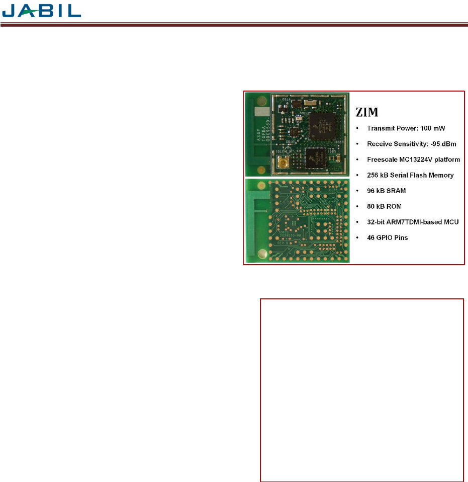
ZIM
1
2.4GHz ZigBee Module - Smart Energy 2.0 Compliant
DESCRIPTION
The ZIM module provides a high performance and cost effective
RF transceiver solution for 2.4 GHz IEEE 802.15.4, ZigBee, and
Zigbee PRO wireless networks with Smart-Energy 2.0
requirements.
The ZIM module combines the Freescale™ MC13224V
transceiver platform with a QE128 microprocessor and includes
an on-board 100mW Power Amplifier. Ideal for remote sensing,
AMR/AMI, home and building automation, industrial control, and
security applications, ZIM-B combines extensive processing
capability with high output power and low power consumption.
The processing power of the MC13224V enables the ZIM-B to
provide a level of integration unprecedented in a ZigBee module.
The 32-bit ARM7TDMI processor and expansive on-chip
memory enable designers to eliminate the peripheral host
processors often required by 8- and 16-bit transceiver solutions.
This high level of integration reduces component count, lower
power consumption and overall system costs.
FEATURES
• Smart-Energy 2.0 “ready”
• Powerful 32-bit ARM7TDMI based microprocessor
• Extensive on-board memory resources
• Up to 100mW output power (+20dBm)
• Miniature footprint: 1.2” x 1.5” (30.5 mm x 38.1 mm)
• Integrated PCB trace antenna
• Optional external antenna
• 16 RF channels
• Over 4000 feet of range (Outdoor LOS)
• AES 128-bit encryption
• Low power consumption
• FCC and IC certifications pending
• RoHS compliant
• Security
• SW Development Kits for Home Automation,
Smart Energy and other application profiles
• “Connector-less” host-board interface
ORDERING INFORMATION
Part Number : ZIM-B/C-WWW-XX-YYYY-ZZ
• Host Interface : B = Land Grid Array, C = Castellation
• WWW : 001 = MC13224V, 002 = MC13224V + QE128, 003 = MC13224V + QE96, 004 = MC13224V + QE64
• With power amp installed, XX = ER. With no power amp, XX = 00.
• With MMCX connector installed, YYYY=EXTA. With inverted-F antenna, YYYY=INTA.
• ZZ = Optional Designators TBD (e.g. Home Automation part? SE1.0? SE2.x?)
Example : 100 mW Output power, Land Grid Array, PCB Trace Antenna, with QE128 (Smart-Energy 2.0) = ZIM-B-002-ER-INTA
APPLICATIONS
• Automated Meter Reading
• Industrial Controls
• Food processing controls
• Traffic Management
• Sensor Networks
• Asset Management
• Barcode reader
• Patient Monitoring
• Glucose monitor
• In meter applications
• Thermostats
• In-home display units
• Home & Building Automation
ZIM
2
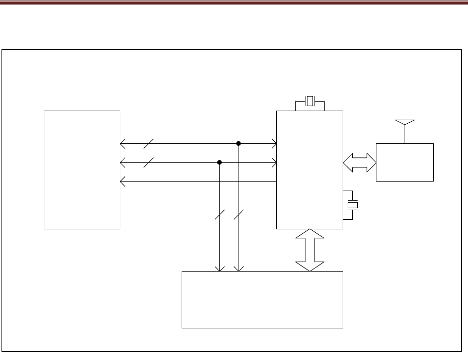
ZIM BLOCK DIAGRAM
RF Front End
(RFMD PA
LPF, Switch)
24 MHz
32.768 kHz
MC13224VQE128
SOC
ZigBee
LGA I/O
SEP 2.0
Co-Processor
UART
WAKE/RESET
Antenna
CLK TRIM
Host Board Interface
ZIM
3
MICROPROCESSOR
The primary component of the ZIM module is Freescale’s third generation ZigBee platform. It incorporates a complete, low power,
2.4GHz radio frequency transceiver, 32-bit ARM7TDMI-based microprocessor, hardware acceleration for both IEEE 802.15.4
MAC and AES security plus a full suite of processor peripherals.
The MC13224V architecture offers superior processing power for ZigBee applications. The core operates up to 26 MHz. An 80
kByte ROM is utilized for the low level IEEE 802.15.4 MAC and Physical layer commands. This off loads the Flash memory,
leaving more space for the end user application. The MC13224V supports 128 kBytes of Flash memory. The program code is
mirrored in 96 kBytes of RAM for faster execution by the processor core. A full set of peripherals and Direct Memory Access
(DMA) capability for transceiver packet data are also included.
In addition, the MC13224V provides extensive power savings options. options, including low current sleep modes allowing for
maximum operating life when battery-powered.
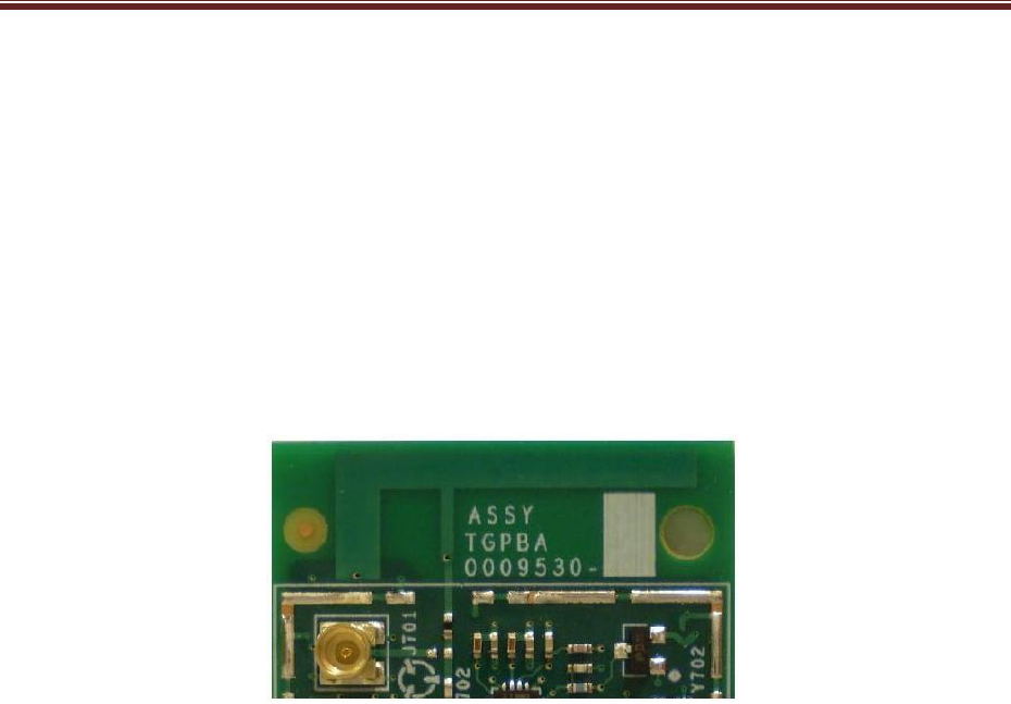
ANTENNA
ZIM modules include an integrated PCB trace antenna. An optional MMCX connector can be specified, enabling connection to a
50-ohm external antenna of the user’s choice. See Ordering Information on page 1.
The PCB antenna employs an F-Antenna topology that is compact and supports an omni-directional radiation pattern. To
maximize antenna efficiency, an adequate ground plane must be provided on the host PCB. Correctly positioned, the ground
plane on the host board under the module will contribute significantly to antenna performance.
The position of the module on the host board and overall design of the product enclosure contribute to antenna performance.
Poor design affects radiation patterns and can result in reflection, diffraction, and/or scattering of the transmitted signal.
Here are some design guidelines to help ensure antenna performance:
• Never place the ground plane or route copper traces directly underneath the antenna portion of the module.
• Never place the antenna close to metallic objects.
• In the overall design, ensure that wiring and other components are not placed near the antenna.
• Do not place the antenna in a metallic or metallized plastic enclosure.
• Keep plastic enclosures 1cm or more from the antenna in any direction.

ZIM
4
MODES OF OPERATION
ZIM power management is controlled through the Freescale MC13224V’s Clock and Reset Module (CRM). The CRM is a
dedicated module to handle clock, reset, and power management functions including control of the power regulators. All these
functions have direct impact on attaining the lowest power.
The ZIM module supports three modes of operation: Active, Doze and Hibernation. The latter two modes are the low-power sleep
modes.
Active Mode
In this mode all functions / features are operating normally.
Doze Mode
Doze mode provides significant reduction in power consumption while still maintaining a high degree of sleep timing accuracy. In
Doze mode, the reference oscillator of the processor continues to operate normally.
Hibernation Mode
Hibernation mode provides the greatest reduction in power consumption however the sleep timing accuracy is not as precise as in
Doze mode.
The CRM manages the recovery from the low-power modes, similar to power-up from reset, providing regulator and clock
management.
The module can be awoken from the low-power modes in 3 ways, wake-up can occur:
• On external interrupts through any of the 4 Keyboard Interface inputs
• From internal interrupts
• On the Real Time (wake-up) timer interrupt
For more detail information on modes of operation refer to Freescale’s MC13224V datasheet available at
Freescale’s website (www.freescale.com)

ZIM
5
HOST-BOARD
A host-board for evaluation purposes is available for configuring and testing the ZIM module. This host board has a USB interface
for connection to a PC whereby SMAC commands can be sent via HyperTerminal.
INTERFACE
The ZIM module has all major pins routed to the host-board interface, this includes, but is not limited, to the pins for JTAG, serial
communication, A/D, etc.
HOST PROTOCOL INTERFACE COMMANDS
Jabil provides the Host Serial and RF Protocols document which details the protocols and commands between the Host processor
(i.e. an external microprocessor, a PC, etc.) and the ZIM module. An example of the commands, but not limited to, included in the
host protocol interface are as follows:
• Query Version (MAC version, SMAC version, etc)
• Set RF Channel
• Set RF Power
• Transmit Packet Error Test
For more detail refer to Jabil ZIM Test SMAC Application User’s Guide ZIM_Test_SMAC_AUG

ZIM
6
*
To meet FCC compliance, the end-user must provide a regulated 3.3 VDC + 1% voltage source to Vcc.
ZIM
7

ZIM
8
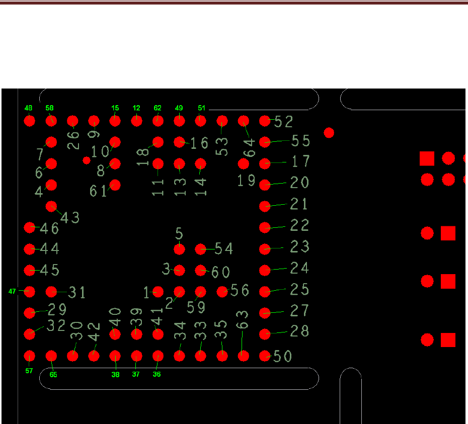
ZIM I/O PIN ASSIGNMENTS
MC13224 Pin
Pin Name
Number Name
Description
1 ZIM_ADC0 1 ADC0 ADC analog input Channel 0/GPIO30
2 ZIM_ADC1 2 ADC1 ADC analog input Channel 0/GPIO31
3 ZIM_ADC2 3 ADC2 ADC analog input Channel 0/GPIO32
4 ZIM_ADC3 4 ADC3 ADC analog input Channel 0/GPIO33
5 ZIM_ADC4 5 ADC4 ADC analog input Channel 0/GPIO34
6 ZIM_ADC5 6 ADC5 ADC analog input Channel 0/GPIO35
7 ZIM_ADC6 7 ADC6 ADC analog input Channel 0/GPIO36
8 ZIM_ADC7 8 ADC7_RTCK ADC analog input Channel 0/ReTurn ClocK/GPIO37
9 ZIM_TDO 9 TDO/GPIO49 JTAG debug port serial data output
10 ZIM_TDI 10 TDI/GPIO48 JTAG debug port serial data input
11 ZIM_TCK 11 TCK/GPIO47 JTAG debug port clock input
12 ZIM_TMS 12 TMS/GPIO46 JTAG debug port test mode select input
13 ZIM_UART2_RTS 13 UART2_RTS UART2 RTS control input/GPIO21
14 ZIM_UART2_CTS 14 UART2_CTS UART2 CTS control output/GPIO20
15 ZIM_UART2_RX 15 UART2_RX UART2 RX receive data input/GPIO19
16 ZIM_UART2_TX 16 UART2_TX UART2 TX transmit data output/GPIO18
17 ZIM_UART1_RTS 17 UART1_RTS UART1 RTS control input/GPIO17
18 ZIM_UART1_CTS 18 UART1_CTS UART1 CTS control output/GPIO16
19 ZIM_UART1_RX 19 UART1_RX UART1 RX receive data input/GPIO15
20 ZIM_UART1_TX 20 UART1_TX UART1 TX transmit data output/GPIO14
21 ZIM_I2C_SDA 21 I2C_SDA I2C bus signal SDA/GPIO13
22 ZIM_I2C_SCL 22 I2C_SCL I2C bus signal SCL/GPIO12
23 ZIM_TMR3 23 TMR3 Counter output or input clock/GPIO11
24 ZIM_TMR2 24 TMR2 Counter output or input clock/GPIO10
25 ZIM_TMR1 25 TMR1 Counter output or input clock/GPIO9
26 ZIM_TMR0 26 TMR0 Counter output or input clock/GPIO8
27 ZIM_SPI_SCK 27 SPI_SCK SPI port Clock/GPIO7
28 ZIM_SPI_MO 28 SPI_MOSI SPI port master out/GPIO6
29 ZIM_SPI_MI 29 SPI_MISO SPI port master in/GPIO5

ZIM
9
30 ZIM_SPI_SS 30 SPI_SS SPI port slave select/GPIO4
31 ZIM_SSI_BITCK 31 SSI_BITCK SSI TX/RX clock/GPIO3
32 ZIM_SSI_FSYN 32 SSI_FSYN SSI frame sync for data/GPIO2
33 ZIM_SSI_RX 33 SSI_RX SSI RX data input/GPIO1
34 ZIM_SSI_TX 34 SSI_TX SSI TX data output/GPIO0
35 ZIM_KBI7 35 KBI_7 Keyboard interface bit 7/GPIO29
36 ZIM_KBI6 36 KBI_6 Keyboard interface bit 6/GPIO28
37 ZIM_KBI5 37 KBI_5 Keyboard interface bit 5/GPIO27
38 ZIM_KBI4 38 KBI_4 Keyboard interface bit 4/GPIO26
39 ZIM_KBI3 39 KBI_3 Keyboard interface bit 3/GPIO25
40 ZIM_KBI2 40 KBI_2 Keyboard interface bit 2/GPIO24
41 ZIM_KBI1 41 KBI_1 Keyboard interface bit 1/GPIO23
42 ZIM_KBI0_HSTWK 42 KBI_0_HST_WK Keyboard interface bit 0/Host Wake Up output/GPIO22
43 ZIM_RESET 51 RESETB Active low, asynchronous reset
44 ZIM_ADC2_REFL 61 ADC2_REFL Low ref voltage for ADC2/GPIO39
45 ZIM_ADC1_REFL 62 ADC1_REFL Low ref voltage for ADC1/GPIO41
46 ZIM_ADC1_REFH 63 ADC1_REFH High ref voltage for ADC1/GPIO40
47 ZIM_ADC2_REFH 64 ADC2_REFH High ref voltage for ADC2/GPIO38
48 ZIM_GND 48 VSS Connect to Ground
49 ZIM_GPIO52 102 MDO01 GPIO52
50 ZIM_GND 50 VSS Connect to Ground
51 ZIM_GPIO54 111 MDO03 GPIO54
52 ZIM_GND 52 VSS Connect to Ground
53 ZIM_GPIO56 120 MDO05 GPIO56
54 ZIM_GPIO57 130 MDO06 GPIO57
55 ZIM_GPIO58 129 MDO07 GPIO58
56 ZIM_GPIO59 114 MSEO0_B GPIO59
57 ZIM_GND 57 VSS Connect to Ground
58 ZIM_GND 58 VSS Connect to Ground
59 ZIM_GPIO62 123 EVTO_B GPIO62
60 ZIM_GPIO63 132 EVTI_B GPIO63
61 ZIM_WAKE_QE 131 MCKO GPIO50

ZIM
10
62 QE_BDM_BKGD NA NA NA
63 ZIM_VCC 44 BK_FB Power Input to module
64 ZIM_VCC 45 VBATT Power Input to module
65 ZIM_VCC NA NA Power Input to module
66 ZIM_VCC NA NA Power Input to module
67- 86 ZIM_GND 75-79, 84-88, 93-97, 104-106, 115 VSS Connect to ground
ZIM
11
ZIM I/O PIN LOCATIONS

ZIM
12
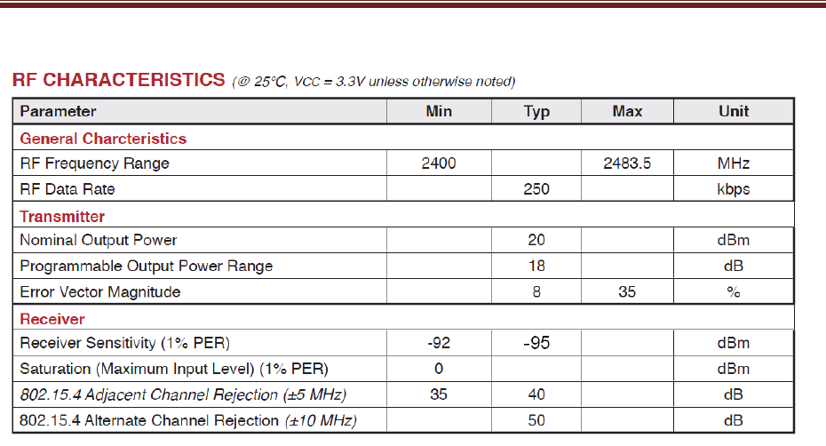
SPECIAL RESTRICTIONS / LIMITATIONS
In order to meet certification requirements, RF power, packet length, and DC supply voltage shall adhere to the following
restrictions.
RF Power
The ZIM module is limited to +20dBm (power register setting = 0x0C) for channels 13 – 23. In order to comply with emissions
requirements, however, the ZIM module must operate at reduced power settings for channels 11-12 and 24-26. The firmware
provided with the modules limits users to power level of +10dBm (power register setting = 0x09) for channels 11, 12, 24, & 25 and
a power level of +6dBm (power register setting = 0x07) for channel 26.
Packet Length
The firmware also limits the maximum data payload to 106 bytes for any transmitted packet.
DC Supply
To ensure FCC compliance, the end-user must provide a regulated 3.3 VDC + 1% voltage source to Vcc.

ZIM
13
AGENCY CERTIFICATIONS
FCC Compliance Statement (Part 15.19) Section 7.15 of RSS-GEN
This device complies with Part 15 of the FCC Rules. Operation is subject to the following two conditions:
1. This device may not cause harmful interference.
2. This device must accept any interference received, including interference that may cause undesired operation.
Warning (Part 15.21)
Changes or modifications not expressly approved by the responsible party could void the user’s authority to operate the
equipment.
This device may only be used with approved antennas that are shipped with the unit and installed per installation instructions. The
use of any other antennas will invalidate the unit’s FCC Part 15 certification.
This device has been designed to operate with the on-board inverted-F antenna. The use of an external antenna will require
authorization. Contact the responsible party for details.
To reduce potential radio interference to other users, the antenna type and its gain should be so chosen that the equivalent
isotropically radiated power (e.i.r.p.) is not more than that permitted for successful communication. Operating the device with the
supplied antenna will ensure that this requirement is met.
Operation is subject to the following two conditions: (1) this device may not cause interference, and (2) this device must accept
any interference, including interference that may cause undesired operation of the device.
20 cm Separation Distance
To comply with FCC/IC RF exposure limits for general population / uncontrolled exposure, the antenna(s) used for this transmitter
must be installed to provide a separation distance of at least 20 cm from all persons and must not be co-located or operating in
conjunction with any other antenna or transmitter.
OEM Responsibility to the FCC Rules and Regulations
The ZIM Module has been certified per FCC Part 15 rules for integration into products without further testing or certification. To
fulfill the FCC certification requirements, the OEM using the ZIM Module must ensure that the information provided on the ZIM
Label is placed on the outside of the final product. The ZIM Module is labeled with its own FCC ID Number and Industry Canada
Certification Number. If these approval numbers are not visible when the module is installed inside another device, then the
outside of the device into which the module is installed must also display a label referring to the enclosed module. This exterior
label can use wording such as the following: “Contains Transmitter Module FCC ID: K4U-ZIM-B IC: 2146A-ZIM-B or “Contains
FCC ID: K4U-ZIM-B IC: 2146A-ZIM-B.
The OEM using the ZIM Module must only use the approved antenna, (PCB Trace Antenna) that has been certified with this
module. The OEM using the ZIM Module must test their final product configuration to comply with Unintentional Radiator Limits
before declaring FCC compliance per Part 15 of the FCC rules.
IC Certification — Industry Canada Statement
The term "IC" before the certification / registration number only signifies that the Industry Canada technical specifications were
met.
Section 14 of RSS-210
The installer of this radio equipment must ensure that the antenna is located or pointed such that it does not emit RF field in
excess of Health Canada limits for the general population. Consult Safety Code 6, obtainable from Health Canada's website:
http://www.hc-sc.gc.ca/ewh-semt/pubs/radiation/99ehd-dhm237/index-eng.php

ZIM
14
REFERENCES & REVISION HISTORY
Reference Documents
Jabil ZIM Test SMAC Application User’s Guide ZIM_Test_SMAC_AUG
FreeScale MC13224V Datasheet
Freescale Semiconductor MC1322x Reference Manual MC1322xRM
Freescale Semiconductor BeeKit™ Quick Start Guide BKWCTKQUG
Freescale Semiconductor BeeKit™ User Guide BKWCTKUG
Freescale Semiconductor Software Driver Reference Manual 22XDRVRRM
Freescale Semiconductor MC1322x Simple Media Access Controller (SMAC) Reference Manual 22xSMACRM
Freescale Semiconductor Simple Media Access Controller (SMAC) User’s Guide SMACRM
IAR J-Link and IAR J-Trace user Guide J-Link_J-TraceARM-1
ARM® IAR Embedded Workbench® IDE User Guide UARM-13
Revision History
Previous Versions
Changes to Current Version
Disclaimer
• The information in this document is current as of April 2010. The information is subject to change without notice.
• No part of this document may be copied or reproduced in any form or by any means without the prior written consent of Jabil. Jabil assumes no responsibility for any errors
that may appear in this document.
• Jabil does not assume any liability for infringement of patents, copyrights or other intellectual property rights of third parties by or arising from the use of Jabil-designed
products listed in this document or any other liability arising from the use of such products. No license, express, implied or otherwise, is granted under any patents, copyrights
or other intellectual property rights of Jabil or others.
• Descriptions of circuits, software and other related information in this document are provided for illustrative purposes in semiconductor product operation and application
examples. The incorporation of these circuits, software and information in the design of a customer’s equipment shall be done under the full responsibility of the customer.
Jabil assumes no responsibility for any losses incurred by customers or third parties arising from the use of these circuits, software and information.
• While Jabil endeavors to enhance the quality, reliability and safety of Jabil-designed products, customers agree and acknowledge that the possibility of defects thereof
cannot be eliminated entirely. To minimize risks of damage to property or injury (including death) to persons arising from defects in Jabil-designed products, customers must
incorporate sufficient safety measures in their design, such as redundancy, fire-containment and anti-failure features.