JADAK a business unit of Novanta HS2R9 RFID/Bluetooth Handheld Scanner User Manual Schematics 2
JADAK LLC RFID/Bluetooth Handheld Scanner Schematics 2
UserManual.wiki
>
JADAK a business unit of Novanta
>
HS2R9 User Manual
Schematics 2
Navigation menu
Upload a User Manual
Namespaces
Wiki Guide
HTML
PDF
Info
Views
User Manual
Discussion / Help
Navigation


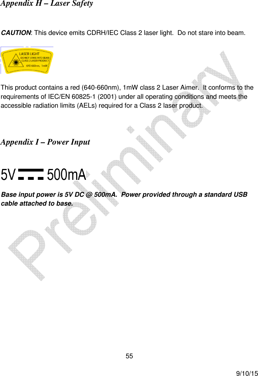
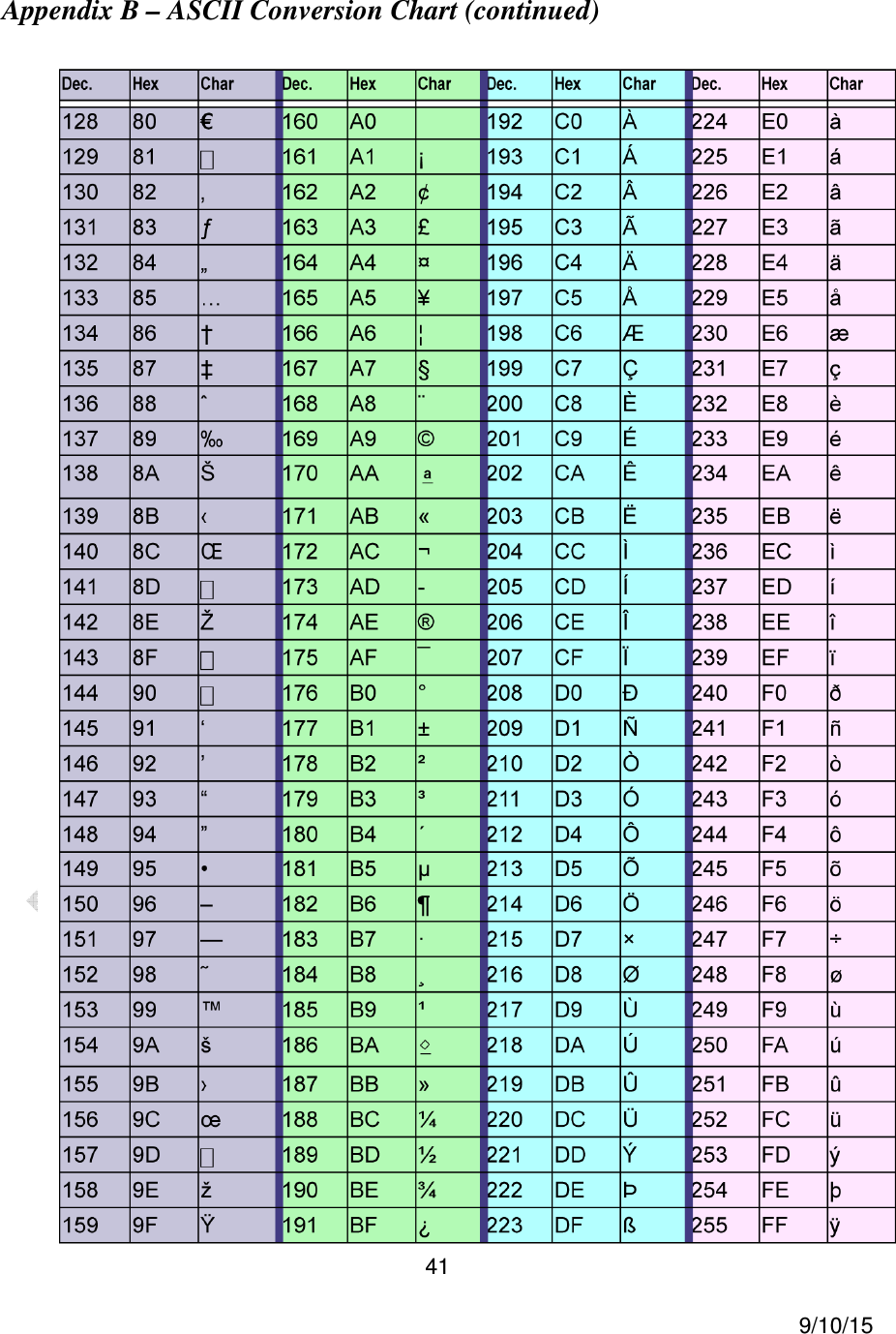
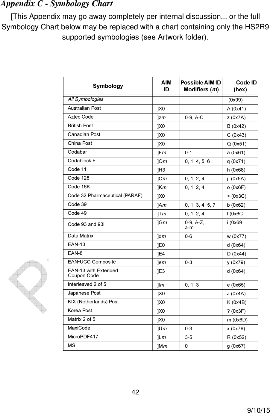
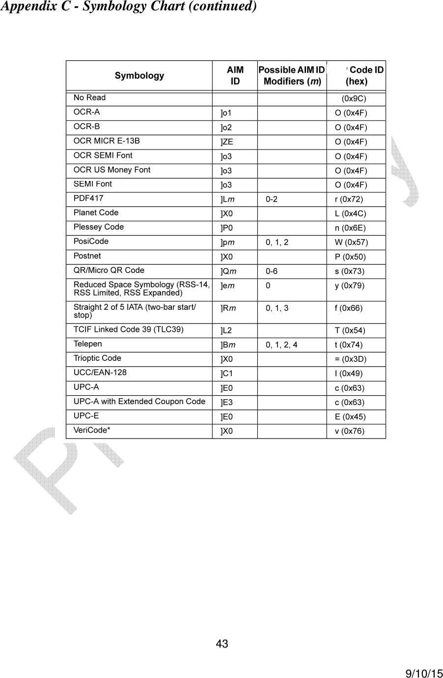
![4 9/10/15 Appendix B – ASCII Conversion Chart (continued) .................................................... 41 Appendix C - Symbology Chart ................................................................................. 42 Appendix C - Symbology Chart (continued) ............................................................... 43 Appendix D - Data Matching, Collation [Needs 7-bit commands] ............................... 44 Appendix E – GS1 Formatting [Needs 7-bit commands] ............................................ 47 Appendix F - Japan 2 Byte Output Mode [Needs 7-bit commands] ............................ 50 Appendix G – HS2R9 Theory of Operation ................................................................ 50 Appendix H – Laser Safety ........................................................................................ 55 Appendix I – Power Input .......................................................................................... 55](https://usermanual.wiki/JADAK-a-business-unit-of-Novanta/HS2R9/User-Guide-2828756-Page-4.png)


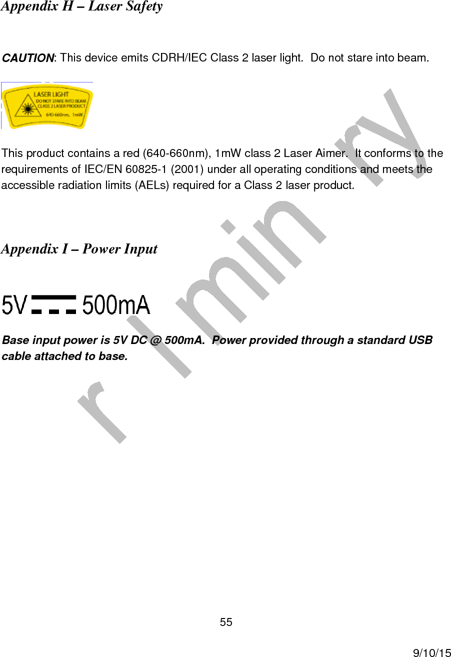
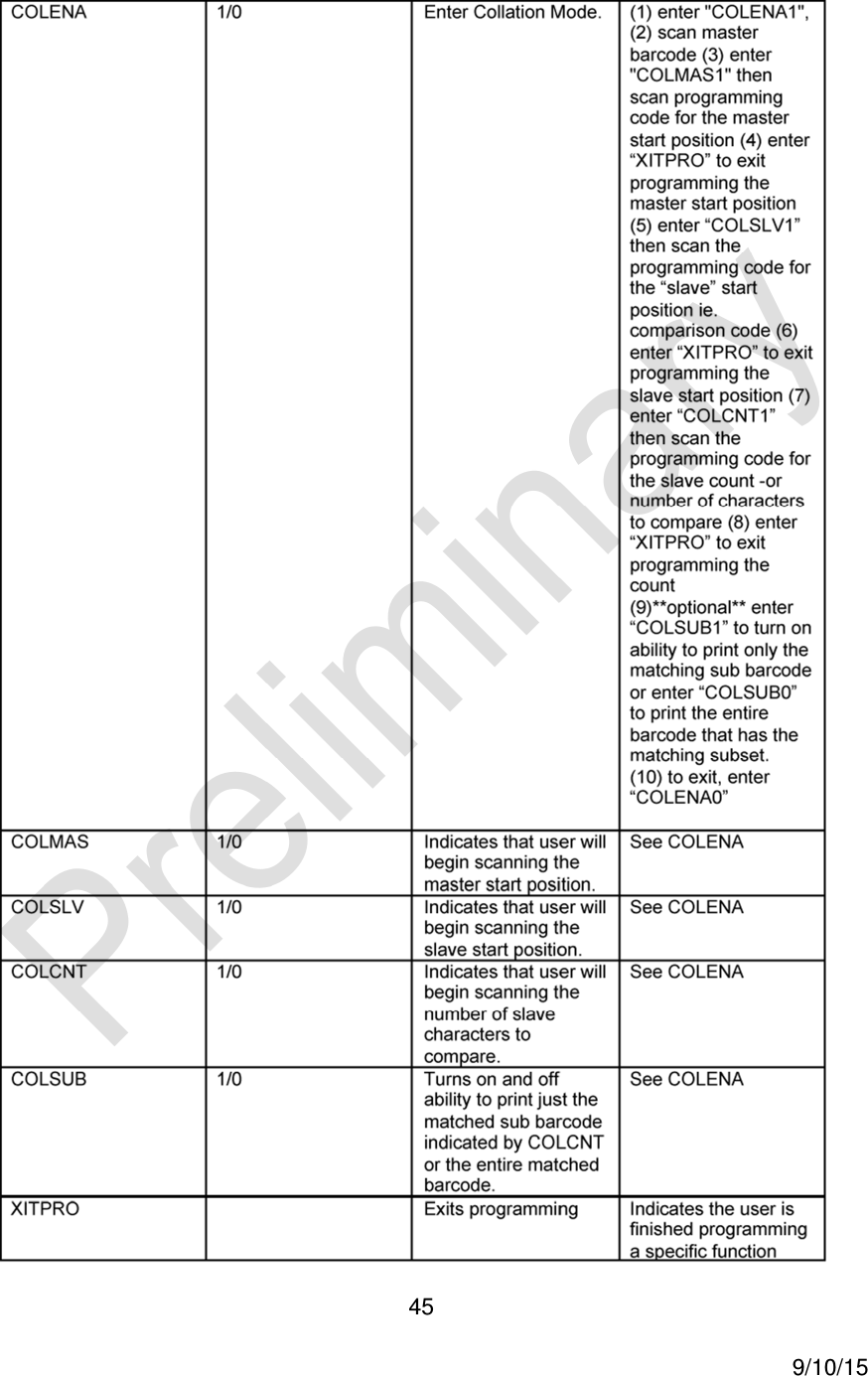
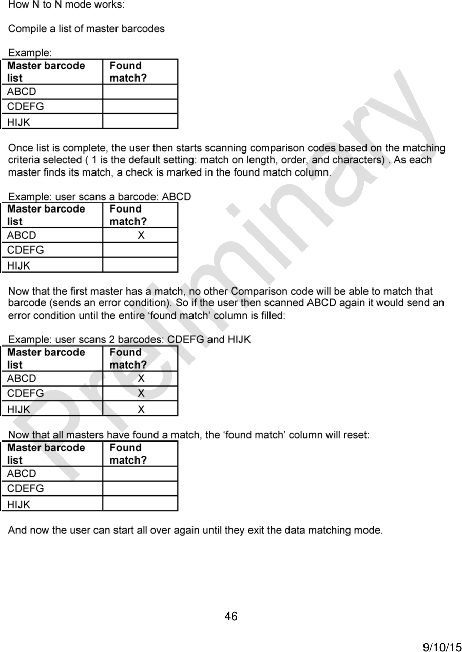
![44 9/10/15 Appendix D - Data Matching, Collation [Needs 7-bit commands]](https://usermanual.wiki/JADAK-a-business-unit-of-Novanta/HS2R9/User-Guide-2828756-Page-44.png)
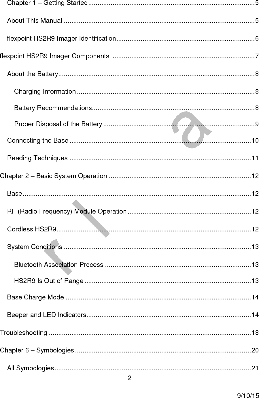
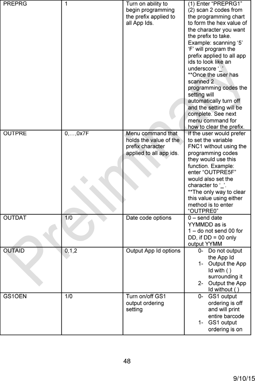
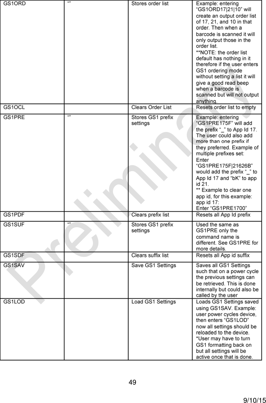
![47 9/10/15 Appendix E – GS1 Formatting [Needs 7-bit commands]](https://usermanual.wiki/JADAK-a-business-unit-of-Novanta/HS2R9/User-Guide-2828756-Page-47.png)
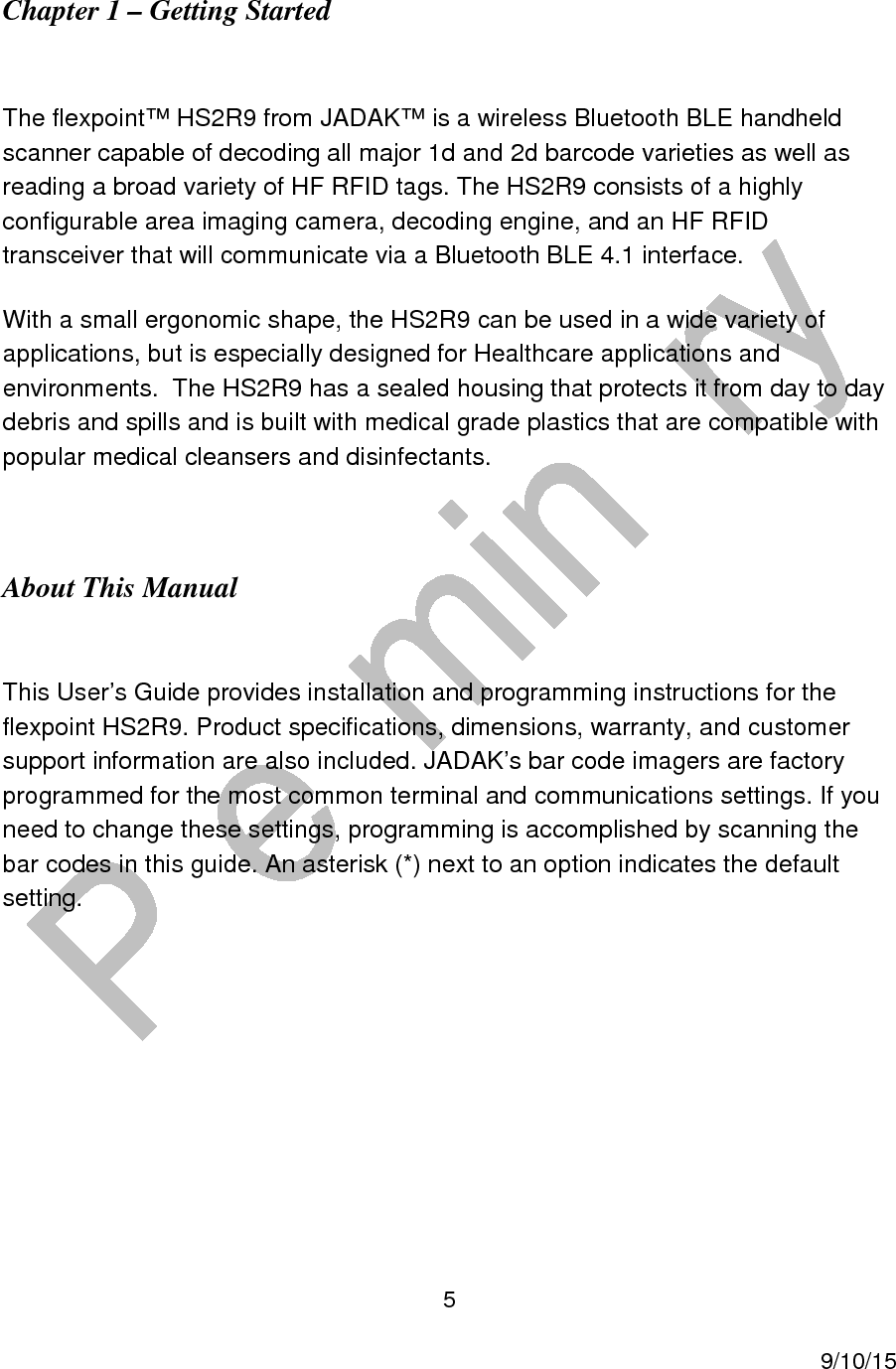
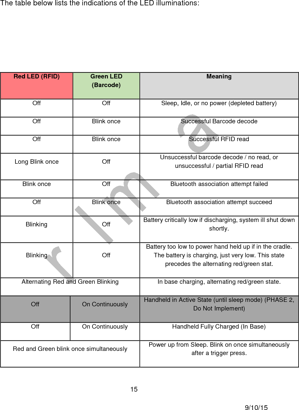
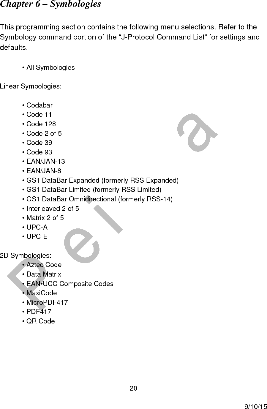
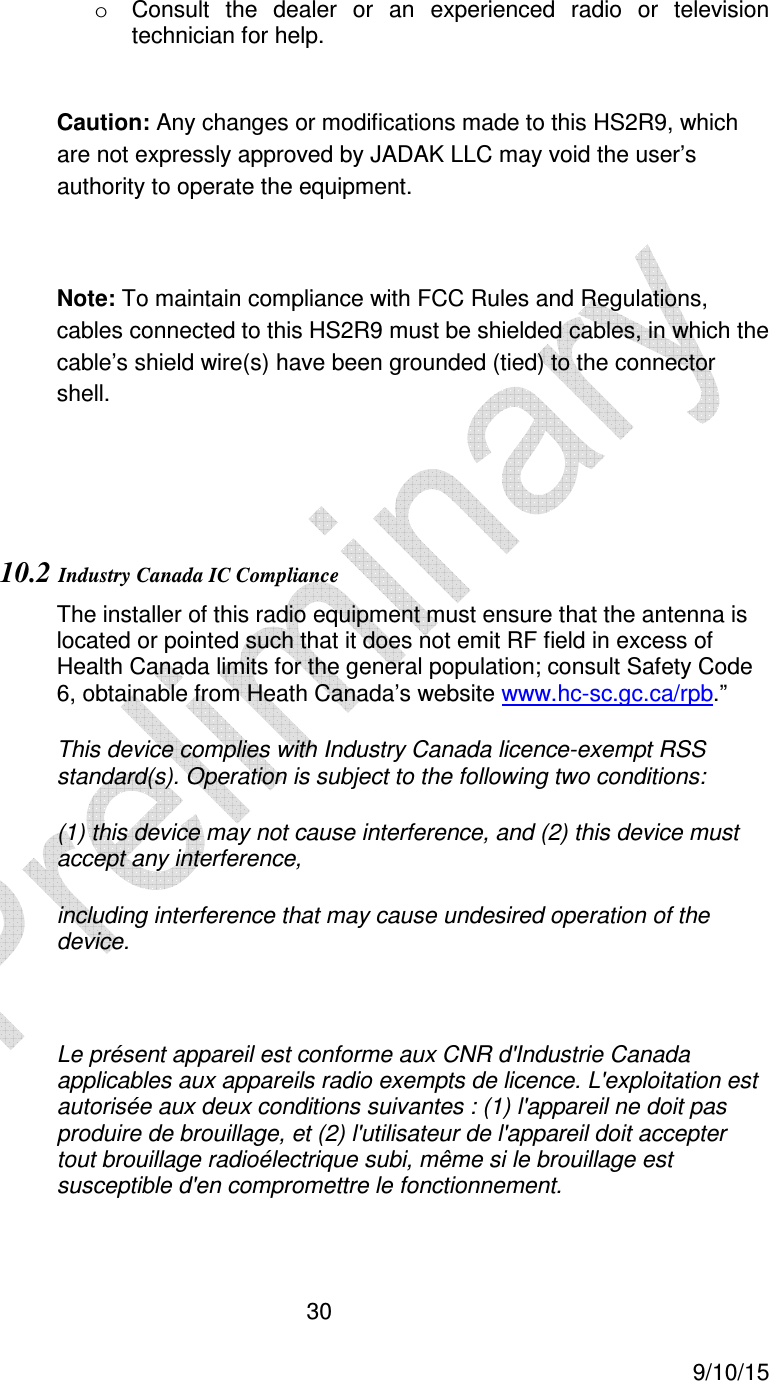
![50 9/10/15 Appendix F - Japan 2 Byte Output Mode [Needs 7-bit commands] Appendix G – HS2R9 Theory of Operation HS2R9 Product Overview The HS2R9 is a wireless Bluetooth BLE handheld scanner capable of decoding all major 1d and 2d barcode varieties as well as reading a broad variety of HF RFID tags. The HS2R9 consists of a highly configurable area imaging camera, decoding engine, and an HF RFID transceiver that will communicate via a Bluetooth BLE 4.1 interface. HS2R9 Operating Description](https://usermanual.wiki/JADAK-a-business-unit-of-Novanta/HS2R9/User-Guide-2828756-Page-50.png)