JADAK a business unit of Novanta HS2R9 RFID/Bluetooth Handheld Scanner User Manual Schematics 2
JADAK LLC RFID/Bluetooth Handheld Scanner Schematics 2
Schematics 2

Flexpoint HS2R9

2
9/10/15
Chapter 1 – Getting Started ......................................................................................... 5
About This Manual ...................................................................................................... 5
flexpoint HS2R9 Imager Identification .......................................................................... 6
flexpoint HS2R9 Imager Components ............................................................................ 7
About the Battery ......................................................................................................... 8
Charging Information ............................................................................................... 8
Battery Recommendations....................................................................................... 8
Proper Disposal of the Battery ................................................................................. 9
Connecting the Base ................................................................................................. 10
Reading Techniques ................................................................................................. 11
Chapter 2 – Basic System Operation ............................................................................ 12
Base .......................................................................................................................... 12
RF (Radio Frequency) Module Operation .................................................................. 12
Cordless HS2R9 ........................................................................................................ 12
System Conditions .................................................................................................... 13
Bluetooth Association Process .............................................................................. 13
HS2R9 Is Out of Range ......................................................................................... 13
Base Charge Mode ................................................................................................... 14
Beeper and LED Indicators........................................................................................ 14
Troubleshooting ............................................................................................................ 18
Chapter 6 – Symbologies .............................................................................................. 20
All Symbologies ......................................................................................................... 21

3
9/10/15
Message Length Description ..................................................................................... 21
Chapter 8 – Product SpecificationsHS2R9 Product Specifications ............................ 23
Chapter 9 – Maintenance .............................................................................................. 26
Cleaning the Scanning Window ................................................................................. 26
Cleaning the Scanner Housing .................................................................................. 26
Interface Cable .......................................................................................................... 28
Replacing the Battery ................................................................................................ 28
Repairs ...................................................................................................................... 28
Chapter 10 – REGULATORY, Service, Maintenance .................................................... 29
10.1 FCC, IC ............................................................................................................. 29
FCC Class B Compliance .......................................................................................... 29
10.2 Industry Canada IC Compliance ........................................................................ 30
10.3 CE ................................................................................................................. 31
10.4 – Customer Support .......................................................................................... 34
Obtaining Technical Assistance or Factory Service ................................................... 34
North America........................................................................................................ 34
Europe ................................................................................................................... 34
10.4 Limited Warranty ............................................................................................... 35
Appendices ............................................................................................................... 37
Appendix A - Programming Bar Codes ...................................................................... 37
Appendix B – ASCII Conversion Chart ...................................................................... 39

4
9/10/15
Appendix B – ASCII Conversion Chart (continued) .................................................... 41
Appendix C - Symbology Chart ................................................................................. 42
Appendix C - Symbology Chart (continued) ............................................................... 43
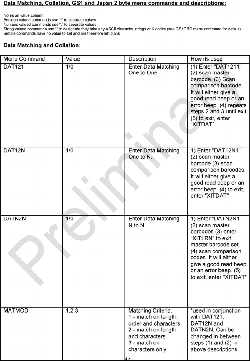
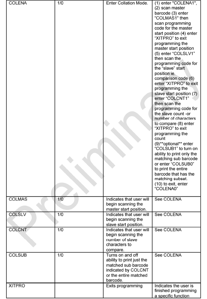
Appendix D - Data Matching, Collation [Needs 7-bit commands] ............................... 44
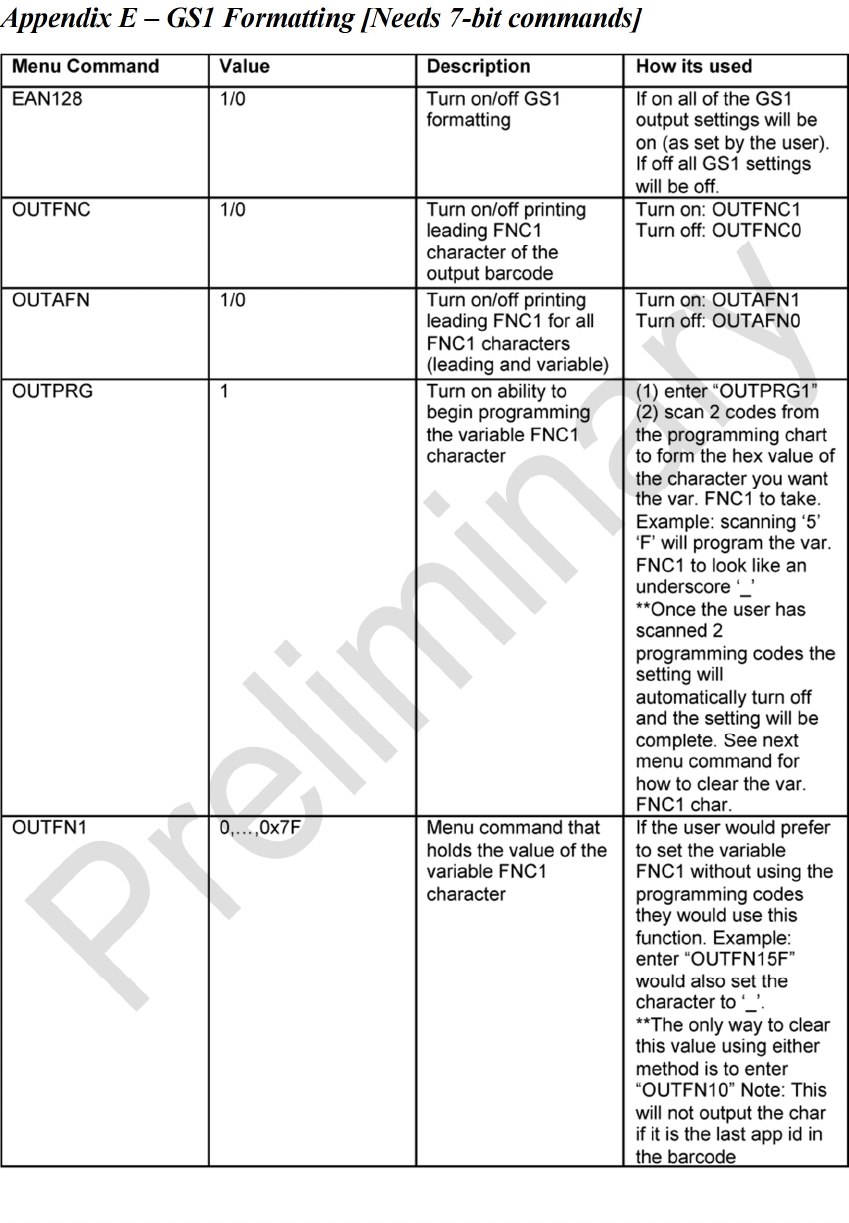
Appendix E – GS1 Formatting [Needs 7-bit commands] ............................................ 47
Appendix F - Japan 2 Byte Output Mode [Needs 7-bit commands] ............................ 50
Appendix G – HS2R9 Theory of Operation ................................................................ 50
Appendix H – Laser Safety ........................................................................................ 55
Appendix I – Power Input .......................................................................................... 55

5
9/10/15
Chapter 1 – Getting Started
The flexpoint™ HS2R9 from JADAK™ is a wireless Bluetooth BLE handheld
scanner capable of decoding all major 1d and 2d barcode varieties as well as
reading a broad variety of HF RFID tags. The HS2R9 consists of a highly
configurable area imaging camera, decoding engine, and an HF RFID
transceiver that will communicate via a Bluetooth BLE 4.1 interface.
With a small ergonomic shape, the HS2R9 can be used in a wide variety of
applications, but is especially designed for Healthcare applications and
environments. The HS2R9 has a sealed housing that protects it from day to day
debris and spills and is built with medical grade plastics that are compatible with
popular medical cleansers and disinfectants.
About This Manual
This User’s Guide provides installation and programming instructions for the
flexpoint HS2R9. Product specifications, dimensions, warranty, and customer
support information are also included. JADAK’s bar code imagers are factory
programmed for the most common terminal and communications settings. If you
need to change these settings, programming is accomplished by scanning the
bar codes in this guide. An asterisk (*) next to an option indicates the default
setting.
6
9/10/15
flexpoint HS2R9 Imager Identification
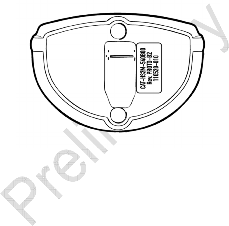
On the bottom of your scanner you will see a label as shown below:
Configuration String:
The configuration string defines the configuration style of the HS2R9 unit.
Please consult the factory for configuration information.
Revision String:
The revision string indicates the revision number of the product. Serial Number:
The serial number format is as follows: YYMMDD-NNN
Where:
YY = Year
MM = Month
DD = Day
NNN = Number of unit
7
9/10/15
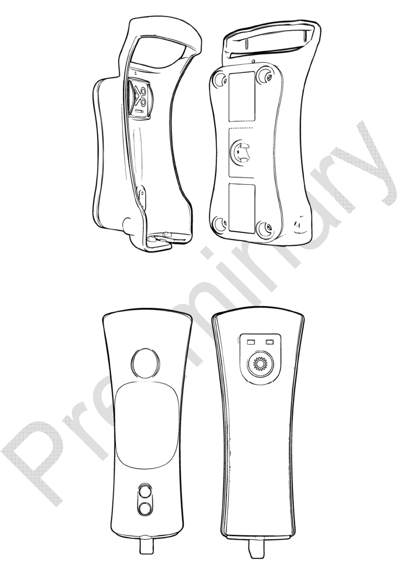
flexpoint HS2R9 Imager Components

8
9/10/15
About the Battery
Power is supplied to the HS2R9 imager by a rechargeable battery located in the
body of the imager. Each HS2R9 imager is shipped with a Lithium Ion battery
already installed. See “HS2R9 Product Specifications” on page 8-1.
Charging Information
The HS2R9 imager is designed to recharge the battery whenever the imager is in
the base. Be sure that the base is connected to an appropriate power supply.
Battery Recommendations
Batteries are shipped approximately 30% to 60% charged and should be
fully charged for maximum charge capacity.
The battery is a lithium ion cell and can be used without a full charge, and
can also be charged without fully discharging, without impacting the
battery life. There is no need to perform any charge/discharge conditioning
on this type of battery.
Do not disassemble the battery. There are no user-serviceable parts in the
battery.
Keep the base connected to power when the host is not in use.
Replace a defective battery immediately since it could damage the imager.
Do not short-circuit a battery or throw it into a fire. It can explode and
cause severe personal injury.

9
9/10/15
The Lithium Ion battery in the HS2R9 can be recharged many times. Eventually
it will be unable to hold a charge and be unusable. See Chapter 9, Replacing the
Battery
A new battery at full charge should allow operation for a full 8 hour shift
given a typical use case of scanning 30 times per hour (triggered for 5
seconds per scan).
Recharging a fully discharged battery will take 3-4 hours depending on the
level of use (scanning) while in the base.
If you are not sure if the battery or charger is working properly please see the
troubleshooting section, in Chapter 2.
Proper Disposal of the Battery
When the battery has reached the end of its useful life, the battery should be
disposed of by a qualified recycler or hazardous materials handler. Do not
incinerate the battery or dispose of the battery with general waste materials. You
may send the imager’s battery to JADAK (postage pre-paid). The shipper is
responsible for complying with all federal, state, and local laws and regulations
related to the packing, labeling, manifesting, and shipping of spent batteries.
Since you may find your cost of returning the batteries significant, it may be more
cost-effective to locate a local recycle/disposal company.
10
9/10/15
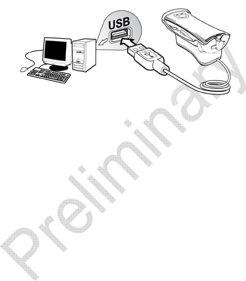
Connecting the Base
The base can be plugged into a computer’s USB port.
When the base is connected, place the HS2R9 imager into the base to charge
the battery. The imager’s indicator LEDs flash, alternating between the green and
red LED, to indicate the battery is charging. If only the red LED is flashing, this
indicates the unit is charging but the voltage/charge is too low to allow operation
(presentation mode) and charging simultaneously. Please wait until the HS2R9’s
LED’s alternate between red and green before attempting to use in presentation
mode while in the base.
11
9/10/15
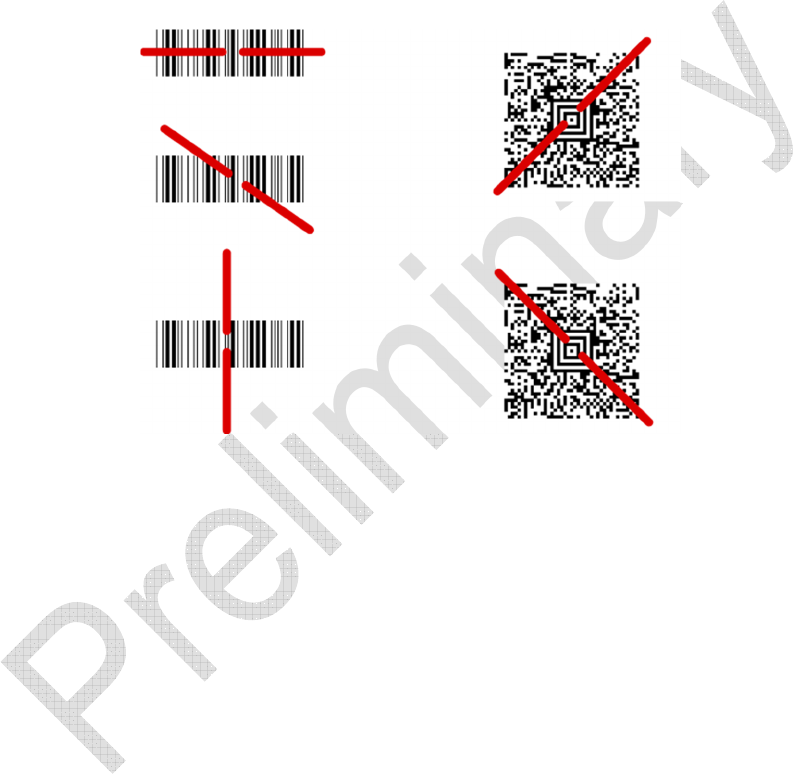
Reading Techniques
The imager has a view finder that projects a bright red or green aiming beam that
corresponds to the imager’s horizontal field of view. The aiming beam should be
centered over the bar code, but it can be positioned in any direction for a good
read.
The aiming beam is smaller when the imager is closer to the code and larger
when it is farther from the code. Symbologies with smaller bars or elements (mil
size) should be read closer to the unit. Symbologies with larger bars or elements
(mil size) should be read farther from the unit. To read a symbol (on a page or on
an object), hold the imager at an appropriate distance from the target, pull the
trigger, and center the aiming beam on the symbol. If the code being scanned is
highly reflective (e.g., laminated), it may be necessary to tilt the code up 15° to
18° to prevent unwanted reflection.

12
9/10/15
Chapter 2 – Basic System Operation
Base
The USB-connected base provides the link between the HS2R9 and the host
system. The base contains an interface assembly and an RF communication
module. The interface assembly performs the data exchange between the
HS2R9 and the host system.
The base is also the HS2R9’s battery charger. Refer to “Base Charge Mode” on
page 2-2 for additional information.
RF (Radio Frequency) Module Operation
The cordless system uses a two-way Bluetooth radio to transmit and receive data
between the HS2R9 and the Base. Designed for point-to point applications, the
radio operates using a license free ISM band, which sends relatively small data
packets at a fast data rate over a radio signal with randomly changing
frequencies, making the cordless system highly responsive to a wide variety of
data collection applications and resistant to noisy RF environments.
Cordless HS2R9
The HS2R9 enables fast and accurate bar code scanning using a non-contact
area image sensor.
The HS2R9 is comprised of an image engine, a decode/control assembly, and an
RF communication module. The image engine performs the bar code image
illumination and sensing. The decode/control assembly coordinates the central
communication activities including: capturing and decoding the bar code image
data, performing software activities (parameter menuing, visual indicator support,
low battery indication), and data translation required for the host system. The RF
communication module performs the data exchange between HS2R9 and the
base.

13
9/10/15
System Conditions
The components of the cordless system interact in specific ways as you
associate an HS2R9 to a base, as you move an HS2R9 out of range, bring an
HS2R9 back in range, or swap HS2R9s between two bases. The following
information explains the cordless system operating conditions.
Bluetooth Association Process
Once an HS2R9 is placed into the base, the HS2R9’s battery charge status is
checked and ,if a sufficient charge is available, the HS2R9 is powered on. The
device will begin the association (establishing a one to one communication link)
process if the Associate on Power-up setting has been enabled. If Associate
on Power-up has not been enabled, the device will not associate with another
device until one of two conditions occur:
• If a base’s Association barcode is scanned (located in the well of the
base in front of the contact pins) the HS2R9 will begin the association
process with the Bluetooth module in that base.
• If a regular barcode is scanned, the HS2R9 will begin the association
process with the last associated device.
HS2R9 Is Out of Range
The HS2R9 is in communication with its base, even when it is not transmitting
bar code data. Whenever the HS2R9 handset cannot communicate with the
base, it is out of range. If the device is out of range and you scan a bar code, the
device will emit a clicking sound as it attempts to re-associate with the base.
If the HS2R9 successfully re-associates with the base, the green indicator
LED will flash once and the device will issue one Good Read (high
frequency) beep. You may then re-scan the bar code.
If the HS2R9 is unable to re-associate with the base after the Bluetooth
association timeout duration (default is 20 seconds), the red indicator LED
will flash once and the device will issue one Error (low frequency) beep.

14
9/10/15
Once you move back into range, you may again attempt to re-associate
the HS2R9 with the base by scanning a bar code. If the device is still
unsuccessful in communicating with the base, you will need to place the
HS2R9 in its base momentarily and scan the Association code in order to
re-link them.
Base Charge Mode
Power is supplied to the HS2R9 imager by a rechargeable battery located in the
body of the device. When the battery level falls below 3.4 Volts, the imager’s red
LED blinks to indicate the low battery situation. The HS2R9 should then be
placed in the USB-connected base to re-charge. When the HS2R9 is charging, it
will indicate this by flashing the red and green LEDs alternately.
If the battery charge falls below 3.2 Volts during use, the red LED will stop
blinking and the HS2R9 will enter sleep mode to preserve battery life. Placing the
HS2R9 into the base will initiate charging. The red LED will begin blinking again
and will continue blinking until the battery level reaches 3.4 Volts, at which point
the red and green LEDs will flash alternately indicating battery charging and
potential use in presentation mode.
Beeper and LED Indicators
The HS2R9 contains LEDs on the top of the unit to indicate its power up,
communication, and battery status. Simply stated, red LED = error; green LED =
success of any type. The HS2R9’s audible indicators have meaning as well, with
a single low-frequency beep indicating an error and a single high-frequency beep
indicating success.

15
9/10/15
The table below lists the indications of the LED illuminations:
Red LED (RFID)
Green LED
(Barcode)
Meaning
Off Off Sleep, Idle, or no power (depleted battery)
Off Blink once Successful Barcode decode
Off Blink once Successful RFID read
Long Blink once Off Unsuccessful barcode decode / no read, or
unsuccessful / partial RFID read
Blink once Off Bluetooth association attempt failed
Off Blink once Bluetooth association attempt succeed
Blinking Off Battery critically low if discharging, system ill shut down
shortly.
Blinking Off
Battery too low to power hand held up if in the cradle.
The battery is charging, just very low. This state
precedes the alternating red/green stat.
Alternating Red and Green Blinking In base charging, alternating red/green state.
Off On Continuously Handheld in Active State (until sleep mode) (PHASE 2,
Do Not Implement)
Off On Continuously Handheld Fully Charged (In Base)
Red and Green blink once simultaneously Power up from Sleep. Blink on once simultaneously
after a trigger press.

16
9/10/15
The table below lists the indications of the beeper:
Function
Active Beeper Tone Beeper Frequency Meaning
Barcode
Single long high beep
Approximate duration
250msec.
Approximate frequency
4,000Hz Successful Decode
Barcode
Single long low beep
Approximate duration
250msec.
Approximate frequency 500Hz Un-Successful Decode /
Barcode No Read
RFID
Single short high beep
Approximate duration
100msec.
Approximate frequency
3,000Hz Successful RFID read
On On
In base, base not powered, both LED’s on constantly.
This state will persist for about 2 minutes, then the unit
will completely power down. The only way to wake it is
to plug it into a powered base.
Blinking for
approximately 12 sec.
Off Power up self-check, internal communications error,
RFID transceiver not detected.
Blinking for
approximately 12 sec. Off
Power up self-check, internal communications error,
barcode scanner not detected. For this error the
scanner will also beep for the same duration of time to
differentiate between error modes.
Off
Blink Once
(After R/NR Beep) Successful Display
Blink Once
(After R/NR Beep) Off (After Unsuccessful Display

17
9/10/15
RFID
Single short low beep
Approximate duration
100msec.
Approximate frequency
200Hz
Un-successful / partial RFID
read
Power up self-
check
initialization
Repeated Long low beeps.
Limit duration to allow other
function to still operate.
Beep and flash red LED for
approximately 12sec then stop
indicators.
Approximate frequency
500Hz
Internal Communications
error on the barcode
scanner.
Power up beep
sequence
Three beeps of increasing
frequency Varying Power up
Bluetooth
Association
Geiger counter beep Bluetooth associating with
base (opening connection)
Two ascending beeps Varying Bluetooth association
successful
One long low beep Varying Bluetooth association failure
Menuing
barcode Two alternating high/low beeps
Varying Menu barcode scanned to
set internal configurations
Sleep mode Three descending beeps Varying
Tone indicates the device is
entering low power mode 2.
Communication will be
closed for power savings
Successful
Display
Single long high beep
Approximate duration
250msec.
4,500hz
Information has been
successfully displayed by
host

18
9/10/15
Unsuccessful
Display
Single long low beep
Approximate duration
250msec.
800Hz
Information has not been
successfully displayed by
host
Troubleshooting
HS2R9 Scanner won’t turn on (scan):
Battery Discharged – place the scanner in base to recharge (ensure the base is
plugged into a powered USB port). A flashing red LED near the top trigger
switch indicates the battery is charging but its’ charge is too low to operate the
HS2R9. This state will eventually change to alternating red and green LED’s
when the charge is sufficient to operate the HS2R9 while still in the base
charging.
The time it takes to transition from a single flashing red LED state to alternating
red and green LED state will depend on how discharged the battery was before
placing into the base. This could take 30-60 minutes or more to change states.
Note – If a functioning HS2R9 is placed into a base that is not powered the
HS2R9 will automatically turn itself off (completely) after approximately 2-3
minutes. This is to prevent the battery from discharging further while in the base.
To turn the HS2R9 on again simply plug the base into a powered USB port with
the HS2R9 in the base.
HS2R9 Scanner won’t communicate with the base:
If after scanning a barcode the HS2R9 emits a clicking sound (association
sound) for a period and then stops first check to ensure the base is plugged into
a powered USB port.

19
9/10/15
If the base was powered scan the association barcode in the well of the base
between the Bluetooth disassociation switch and the charging contact pins. The
HS2R9 should then emit a clicking should for a short period while associating
with the Bluetooth module in the base. Upon a successful Bluetooth association
the HS2R9 will flash the green LED and emit a single short high frequency beep.
HS2R9 Scanner will not send data to the host:
If the HS2R9 is associated with the base but no data is being received by the
host system check that the USB driver is installed on the host and the base has
enumerated correctly.
Factory Contact:
If you are unable to resolve the problem with the HS2R9 after reading the
troubleshooting section please use the contact information in chapter 10 for
assistance.

20
9/10/15
Chapter 6 – Symbologies
This programming section contains the following menu selections. Refer to the
Symbology command portion of the “J-Protocol Command List” for settings and
defaults.
• All Symbologies
Linear Symbologies:
• Codabar
• Code 11
• Code 128
• Code 2 of 5
• Code 39
• Code 93
• EAN/JAN-13
• EAN/JAN-8
• GS1 DataBar Expanded (formerly RSS Expanded)
• GS1 DataBar Limited (formerly RSS Limited)
• GS1 DataBar Omnidirectional (formerly RSS-14)
• Interleaved 2 of 5
• Matrix 2 of 5
• UPC-A
• UPC-E
2D Symbologies:
• Aztec Code
• Data Matrix
• EAN•UCC Composite Codes
• MaxiCode
• MicroPDF417
• PDF417
• QR Code

21
9/10/15
All Symbologies
If you want to decode all the symbologies allowable for your imager, scan the All
Symbologies On code. If on the other hand, you want to decode only a particular
symbology, scan All Symbologies Off followed by the On symbol for that
particular symbology.
Message Length Description
You are able to set the valid reading length of some of the bar code symbologies.
If the data length of the scanned bar code doesn’t match the valid reading length,
the imager will issue an error beep. You may wish to set the same value for
minimum and maximum length to force the imager to read fixed length bar code
data. This helps reduce the chances of a misread.
EXAMPLE: Decode only those bar codes with a count of 9-20 characters.
Min. length = 09 Max. length = 20
EXAMPLE: Decode only those bar codes with a count of 15 characters.
Min. length = 15 Max. length = 15
For a value other than the minimum and maximum message length defaults,
scan the bar codes included in the explanation of the symbology, then scan the
digit value of the message length and Save bar codes from “Appendix A -
Programming Bar Codes” on page A-1. The minimum and maximum lengths and
the defaults are included with the respective symbologies.

22
9/10/15

23
9/10/15
Chapter 8 – Product SpecificationsHS2R9 Product Specifications
Parameter
Specification
Dimensions (Typical):
Height
Length
Width
Weight
1.31 inches (34.4 mm)
4. 6 inches (116.8 mm)
2.02 inches (51.3 mm)
4.0 ounces (113.4 g)
Aimer:
Illumination LEDS
Aiming LEDS
626 nm ± 30 nm
526 nm ± 30 nm
Image VGA, 752x480
Skew Angle ± 40 degrees
Pitch Angle ± 40 degrees
Horizontal Velocity 4 inches (10 cm) per second
Scan Contrast 20% minimum for linear and Matrix codes

24
9/10/15
Battery:
Lithium Ion
Battery Capacity:
Standby
Heavy Usage (1 scan
per second)
Storage:
3.7 Volt, 950 mAHr minimum
20 hours
12 hours (maximum)
5% loss per month
Parameter
Specification
Voltage Requirements of Base:
USB Power
5V (@ 500 mA maximum)
Current Draw of Base (Max @
5VDC): HS2R9 in base,
Presentation Mode
HS2R9 Base without Handheld
Scanning Standby Inrush
475 mA 125 mA 950 mA
200mA 100mA 700mA
Power Supply:
Noise Rejection
Maximum 100 mV peak to peak, 10 to 100 kHz
Radio:
Frequency
Bluetooth Low Energy 4.1
2.4 to 2.48 GHz (ISM Band)
Temperature Ranges:
Operating
Battery Charge (Presentation
Mode)
Battery Charge (Standby Mode)
Storage
+32° F to +122° F (0° C to +50° C)
+32° F to +95° F (0° C to 35° C)
+32° F to +113° F (0° C to 45° C)
-40° F to +140° F (-40° C to +60° C)
Humidity 0 to 95% non-condensing

25
9/10/15
Parameter
Specification
MTBF Per MIL-HDBK-217F Ground Benign exceeds
100,000 hours
Sealant Rating IP54

26
9/10/15
Chapter 9 – Maintenance
The HS2R9 provides reliable and efficient operation with a minimum of care. Although
specific maintenance is not required, the following periodic checks ensure dependable
product operation:
Cleaning the Scanning Window
Reading performance may degrade if the scanner’s window is not clean. If the window is
visibly dirty, or if the scanner isn’t operating well, clean the window with a soft cloth or
lens tissue dampened with water (or a mild detergent-water solution). If a detergent
solution is used, rinse with a clean lens tissue dampened with water only.
Cleaning the Scanner Housing
The HS2R9 is IP54 rated when the cable is attached. This means that liquids and dusts
will not penetrate into the housing; however, the scanner should not be submerged in
water or other liquids. It is also good practice to dampen the cleansing cloth versus
spraying the scanner directly.

27
9/10/15
The HS2R9 housing is compatible with the following cleaners:
Standard Cleaning Agents and Hand Sanitizers
Cleaning Agents Dilution
10% Bleach 1 part bleach to 9 parts water
70% isopropyl alcohol (IPA) No dilution required
Compublend II (Base V with fragrance) 0.5 oz/gallon water
Aseptizyme 1 oz/gallon water
Clorox Wipes Not applicable
Detergezyme 1 oz/gallon water
Dispatch No dilution required
Hibiclens 25.6 oz/gallon water
LpH Disinfectant Cleaner 0.5 oz/gallon water
Maxima 128 1 oz/gallon water
Metrizyme 1 oz/gallon water
Mild detergent Per manufacturer’s recommendation, as needed
Expose 256 0.5 oz/gallon water
Super Sani-Cloth Not applicable
Virkon Per manufacturer’s recommendation
Warm water Not applicable
Wexcide 1 oz/gallon water
Wexcide-Ready-To-Use No dilution required
Hand sanitizers
Purell w/ 65% Alcohol No dilution required
3M Avagard D No dilution required
EcoLab Quik-Care No dilution required

28
9/10/15
Interface Cable
Inspect the USB interface cable and connector for wear or other signs of damage. A
badly worn cable or damaged connector may interfere with scanner operation.
Should the cable be damaged, the cable can be replaced in the field.
Note: The use of non-JADAK cables voids the warranty; only a JADAK cable can be
used to keep the IP54 rating.
Replacing the Battery
Replace the battery in the HS2R9 with a battery supplied by JADAK only. For
instructions on replacing the battery see the HS2R9 Battery Replacement Guide.
Repairs
Repairs and/or upgrades are not to be performed on this product. These services are to
be performed by JADAK only. Please contact JADAK for your service needs.

29
9/10/15
Chapter 10 – REGULATORY, Service, Maintenance
The product is designed to support the following regulatory and
safety standards as a standalone unit. The end user will need to
verify general EMC compliance as implemented in their host system.
The end user will not need to verify RFID radio compliance since
JADAK LLC tested the HS2R9 and received modular certification for
this portion of the product.
10.1 FCC, IC
FCC Class B Compliance
This device complies with Part 15 of the FCC Rules. Operation is
subject to the following two conditions:
1. This device may not cause harmful interference.
2. This device must accept any interference received, including
interference that may cause undesired operation.
This equipment has been tested and found to comply with the limits
for a Class B digital device, pursuant to part 15 of the FCC Rules.
These limits are designed to provide reasonable protection against
harmful interference in a residential installation. This equipment
generates, uses, and can radiate radio frequency energy and, if not
installed and used in accordance with the instructions, may cause
harmful interference to radio communications. However, there is no
guarantee that interference will not occur in a particular installation. If
this equipment does cause harmful interference to radio or television
reception, which can be determined by turning the equipment off and
on, the user is encouraged to try to correct the interference by one or
more of the following measures:
o Reorient or relocate the receiving antenna.
o Increase the separation between the equipment and receiver.
o Connect the equipment into an outlet on a circuit different from
that to which the receiver is connected.

30
9/10/15
o Consult the dealer or an experienced radio or television
technician for help.
Caution: Any changes or modifications made to this HS2R9, which
are not expressly approved by JADAK LLC may void the user’s
authority to operate the equipment.
Note: To maintain compliance with FCC Rules and Regulations,
cables connected to this HS2R9 must be shielded cables, in which the
cable’s shield wire(s) have been grounded (tied) to the connector
shell.
10.2
Industry Canada IC Compliance
The installer of this radio equipment must ensure that the antenna is
located or pointed such that it does not emit RF field in excess of
Health Canada limits for the general population; consult Safety Code
6, obtainable from Heath Canada’s website www.hc-sc.gc.ca/rpb.”
This device complies with Industry Canada licence-exempt RSS
standard(s). Operation is subject to the following two conditions:
(1) this device may not cause interference, and (2) this device must
accept any interference,
including interference that may cause undesired operation of the
device.
Le présent appareil est conforme aux CNR d'Industrie Canada
applicables aux appareils radio exempts de licence. L'exploitation est
autorisée aux deux conditions suivantes : (1) l'appareil ne doit pas
produire de brouillage, et (2) l'utilisateur de l'appareil doit accepter
tout brouillage radioélectrique subi, même si le brouillage est
susceptible d'en compromettre le fonctionnement.

31
9/10/15
Under Industry Canada regulations, this radio transmitter may only
operate using an antenna of a type and maximum (or lesser) gain
approved for the transmitter by Industry Canada.
To reduce potential radio interference to other users, the antenna type
and its gain should be so chosen that the equivalent isotropically
radiated power (e.i.r.p.) is not more than that necessary for successful
communication.
Conformément à la réglementation d'Industrie Canada, le présent
émetteur radio peut fonctionner avec une antenne d'un type et d'un
gain maximal (ou inférieur) approuvé pour l'émetteur par Industrie
Canada.
Intentional Radiator Modular Certification of the HS2R9
The HS2R9 also contains intentional radiators, the RFID transceiver
and Bluetooth Low Energy communications. JADAK’s approach to
agency testing and certification for this was to get modular certification
to facilitate easier integration of the device into end user systems. In
most circumstances the integrator will not need to re-certify the
intentional radiator, rather they can reference JADAK’s certifications
listed under the following:
Model Number: HS2R9
FCC ID: 2AAVI-HS2R9
IC: 11355A-HS2R9
10.3 CE
The product conforms to the following EU directives:

32
9/10/15
Manufacturer
JADAK LLC
Address
7279 William Barry Blvd, North Syracuse NY 13212
Product Description
CAT
-
HS2R9, Barcode / RFID Scanner, Model Number:
HS2R9
The described product conforms to the requirements of the following EU Directives:
LOW VOLTAGE DIRECTIVE
2006/95/EC as amended
Council Directive of December 12, 2006 on the harmonization of the laws of Member States relating to electrical
equipment designed for use within certain voltage limits
EMC DIRECTIVE 2004/108/EC as amended
Council Directive of December 15, 2004 on the approximation of the laws of the Member States relating to
electromagnetic compatibility
ROHS DIRECTIVE 2011/65/EU
Directive 2011/65/EU of the European Parliament and of the Council of 8
th
June 2011 on the restriction of the
use of certain hazardous substances in electrical and electronic equipment
WEEE DIRECTIVE 2012/19/EU

33
9/10/15
Directive 2012/19/EU of the European Parliament and of the Council of 4
th
July 2012 on waste electrical and
electronic equipment.
FIRST YEAR OF THE CE MARKING 2015
Conformity of the product with the requirements of EU directives is established through full compliance with
the following standards:
Harmonised European Normes
Standard Year + Amendments Description
EN 60950-1 2006+A11:2009+A1:2010+A12:2011 Product Safety
EN 62471 2008 LED Safety
EN 50581 2012 RoHS
EN 55024 2010 Immunity
EN 55022 2010 EME
EN 61000-3-2 2006+A1:2009+A2:2009 Harmonics (current < 16A)
EN 61000-3-3 2008 Flicker (current < 16A)
ICES-003 Issue 5 2012 Emissions, Conducted and
Radiated
EN 300 330-1 V1.7.1 2010 RFID (Radio)
EN 301 489-1 V1.9.2 2011 RFID (EMC)
EN 301 489-3 V1.6.1 2002 RFID (EMC)
FCC KDB’s and RSS-102 Issue 5 EMF (Safety)
FCC RF Testing & Report per Part
15C for 13.56 MHz RFID
RFID
CFR47 Part 15 Subpart B Radiated Emissions
FCC 15.225/IC RSS-210 Radiated Emissions
RSS-GEN Issue 4 November 2014 Radio Standards Specification
RSP-100 Issue 10 November 2014 Radio Standards Specification

34
9/10/15
10.4 – Customer Support
Obtaining Technical Assistance or Factory Service
JADAK provides assistance and service for all its products. To obtain warranty or non-
warranty service, return the unit to JADAK (postage paid) with a copy of the dated
purchase record attached. Contact the appropriate location below to obtain a Return
Material Authorization number (RMA #) before returning the product.
If you need assistance installing or troubleshooting your scanner, please contact the
JADAK office in your area.
North America
JADAK, LLC
Telephone: +1 315-701-0678
Fax: +1 315-701-0679
E-mail: info@jadaktech.com
Europe
JADAK BV
Telephone +31 (0)76-522-5588
Fax : +31 (0)76-522-4747
E-mail: info@jadaktech.com

35
9/10/15
10.4 Limited Warranty
JADAK LLC (“JADAK”) warrants the HS2R9 to be free from defects in materials and
workmanship and to conform to JADAK’s published specifications applicable to the
products purchased at the time of shipment. This warranty does not cover the interface
cable and does not include any JADAK product which is (i) improperly installed or used;
(ii) damaged by accident or negligence, including failure to follow the proper
maintenance, service, and cleaning schedule; or (iii) damaged as a result of: (A)
Modification or alteration by the purchaser or other party, (B) Excessive voltage or
current supplied to or drawn from the interface connections, (C) Static electricity or
electro-static discharge, (D) Operation under conditions beyond the specified operating
parameters, or (E) Repair or service of the product by anyone other than JADAK or its
authorized representatives.
This warranty shall extend from the time of shipment for the duration published by
JADAK for the product at the time of purchase (“Warranty Period”). Any defective
product must be returned (at purchaser’s expense) during the Warranty Period to
JADAK factory for inspection. No product will be accepted by JADAK without a Return
Materials Authorization, which may be obtained by contacting JADAK. In the event that
the product is returned to JADAK within the Warranty Period and JADAK determines to
its satisfaction that the product is defective due to defects in materials or workmanship,
JADAK, at its sole option, will either repair or replace the product without charge, except
for return shipping to JADAK.
EXCEPT AS MAY BE OTHERWISE PROVIDED BY APPLICABLE LAW, THE
FOREGOING WARRANTY IS IN LIEU OF ALL OTHER COVENANTS OR
WARRANTIES, EITHER EXPRESSED OR IMPLIED, ORAL OR WRITTEN,
INCLUDING, WITHOUT LIMITATION, ANY IMPLIED WARRANTIES OF
MERCHANTABILITY OR FITNESS FOR A PARTICULAR PURPOSE.

36
9/10/15
JADAK’S RESPONSIBILITY AND PURCHASER’S EXCLUSIVE REMEDY UNDER
THIS WARRANTY IS LIMITED TO THE REPAIR OR REPLACEMENT OF THE
DEFECTIVE PRODUCT WITH NEW OR REFURBISHED PARTS. IN NO EVENT
SHALL JADAK BE LIABLE FOR INDIRECT, INCIDENTAL, OR CONSEQUENTIAL
DAMAGES, AND, IN NO EVENT, SHALL ANY LIABILITY OF JADAK ARISING IN
CONNECTION WITH ANY PRODUCT SOLD HEREUNDER (WHETHER SUCH
LIABILITY ARISES FROM A CLAIM BASED ON CONTRACT, WARRANTY, TORT, OR
OTHERWISE) EXCEED THE ACTUAL AMOUNT PAID TO JADAK FOR THE
PRODUCT. THESE LIMITATIONS ON LIABILITY SHALL REMAIN IN FULL FORCE
AND EFFECT EVEN WHEN JADAK MAY HAVE BEEN ADVISED OF THE
POSSIBILITY OF SUCH INJURIES, LOSSES, OR DAMAGES. SOME STATES,
PROVINCES, OR COUNTRIES DO NOT ALLOW THE EXCLUSION OR LIMITATIONS
OF INCIDENTAL OR CONSEQUENTIAL DAMAGES, SO THE ABOVE LIMITATION OR
EXCLUSION MAY NOT APPLY TO YOU.
All provisions of this Limited Warranty are separate and severable, which means that if
any provision is held invalid and unenforceable, such determination shall not affect the
validity of enforceability of the other provisions hereof. Use of any peripherals not
provided by the manufacturer may result in damage not covered by this warranty. This
includes but is not limited to: cables, power supplies, cradles, and docking stations.
JADAK extends these warranties only to the first end users of the products. These
warranties are non-transferable. The duration of the limited warranty for the flexpoint
HS2R9 is for one (1) year.

37
9/10/15
Appendices
Appendix A - Programming Bar Codes

38
9/10/15
39
9/10/15
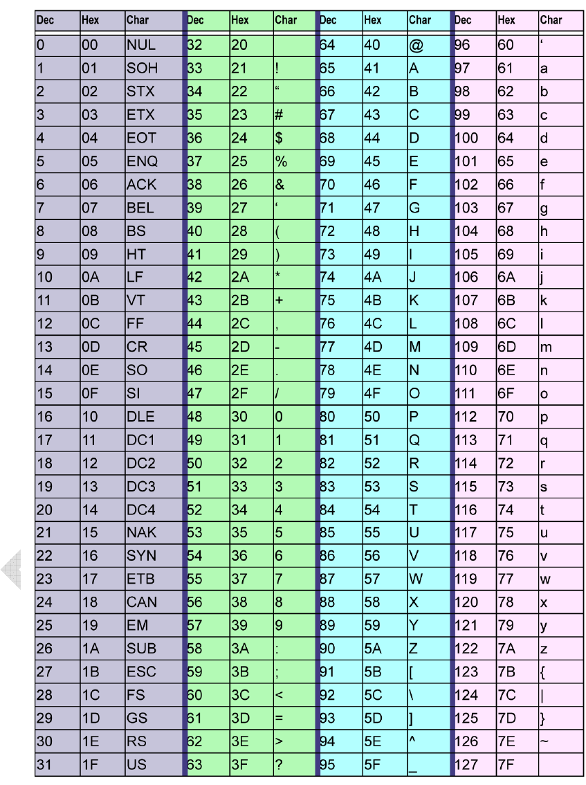
Appendix B – ASCII Conversion Chart

40
9/10/15
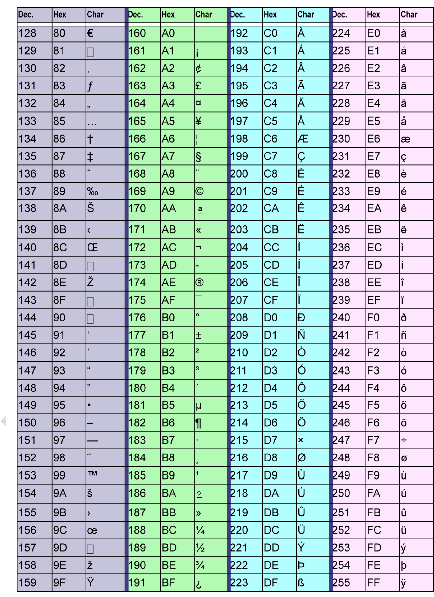
41
9/10/15
Appendix B – ASCII Conversion Chart (continued)
42
9/10/15
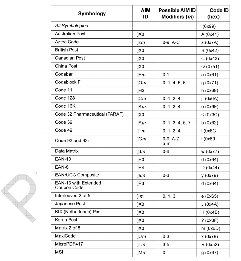
Appendix C - Symbology Chart
[This Appendix may go away completely per internal discussion... or the full
Symbology Chart below may be replaced with a chart containing only the HS2R9
supported symbologies (see Artwork folder).
43
9/10/15
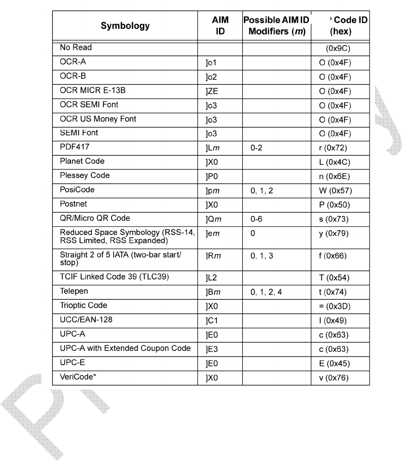
Appendix C - Symbology Chart (continued)
44
9/10/15
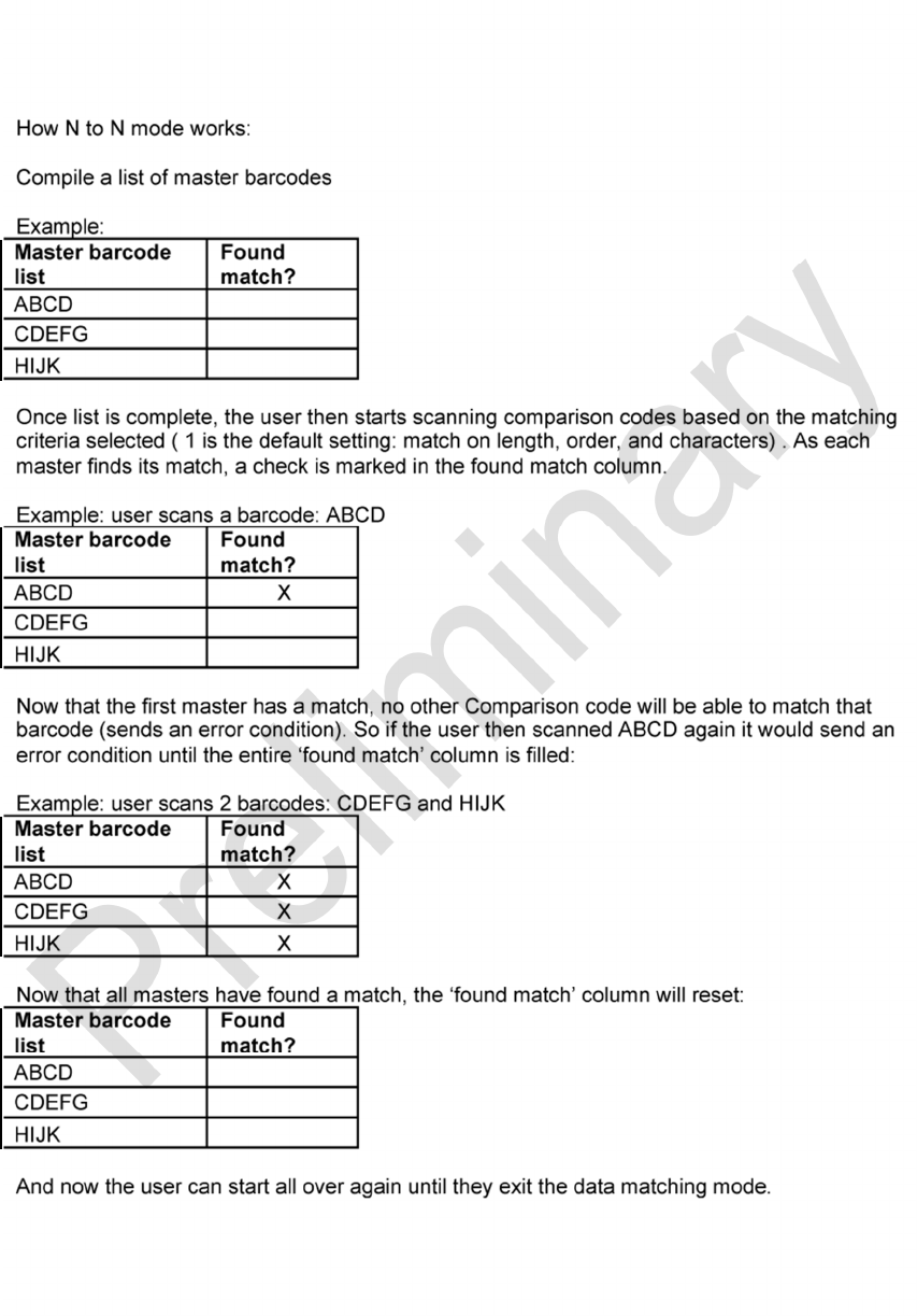
Appendix D - Data Matching, Collation [Needs 7-bit commands]
45
9/10/15
46
9/10/15
47
9/10/15
Appendix E – GS1 Formatting [Needs 7-bit commands]
48
9/10/15
49
9/10/15
50
9/10/15
Appendix F - Japan 2 Byte Output Mode [Needs 7-bit commands]
Appendix G – HS2R9 Theory of Operation
HS2R9 Product Overview
The HS2R9 is a wireless Bluetooth BLE handheld scanner capable of decoding all major
1d and 2d barcode varieties as well as reading a broad variety of HF RFID tags. The
HS2R9 consists of a highly configurable area imaging camera, decoding engine, and an
HF RFID transceiver that will communicate via a Bluetooth BLE 4.1 interface.
HS2R9 Operating Description

51
9/10/15
The unit can read both RFID and barcode, but not simultaneously. If the unit is not
triggered to read barcodes (top trigger button is not pressed or not serially triggered), the
unit will be in RFID mode actively scanning for RFID tags.
When the unit is triggered to read a barcode (top trigger button is pressed or serially
triggered), the RFID transceiver will be put into low power mode before enabling the
barcode scanner. Conversely either after a barcode scan or trigger release (manual or
serial), the barcode reader is put into low power mode before enabling the RFID
transceiver. When the RFID portion of the scanner is active it is attempting to read ISO
15693 tags as our current customer requirements are only for that tag type.
Alternating the operational modes described above reduces current draw to extend
battery life. The beeper is also only activated after the barcode reader is off to keep
current draw at a minimum.
NOTE: A special version of firmware was developed for the HS2R9 specifically for
agency RFID modular testing. This firmware allow for independent selection of one of
four different tag types which encompass the four different modulation techniques of the
transceiver. When any one of these four different modes is selected, this is the only
modulation technique active, and the HS2R9 will then only read that specific tag type.
HS2R9 Technical Description
The HS2R9 consists of four subsections:
1 – Barcode scanner.
2 – RFID transceiver and antenna (transceiver is NXP CLRC663).

52
9/10/15
3 – Microcontroller (Freescale Kinetis, MKL25Z128VLH4).
4 – Bluetooth Module (Microchip, RN4020-V/RM).
1 – The Barcode scanner consists of two major components, the imager engine and the
decoder board. The imager engine contains a CMOS imaging sensor and separate
external illumination. The decoder board contains a microprocessor with external RAM
and FLASH used to capture and process images from the image engine.
2 – The RFID transceiver and antenna consist of an NXP RFID transceiver part number
CLRC66301HN,551 and a custom loop antenna. The loop antenna is essential a flex
circuit that mounts around the image engine and interfaces to the circuit board housing
the CLRC663 via a flex circuit and connector on the interface board. The antenna is
shielded on both along the length of the flex tail up to the loop portion. The shield is tied
to the ground trace on the antenna which is tied directly to the ground of the circuit
board.
3 – The Microcontroller on the interface board controls the power and communications
links between itself and both the barcode scanner and the RFID transceiver.
The communication link between the barcode scanner and the microcontroller is via a
RS-232 interface.
The communication link between the RFID transceiver and the microcontroller is via a
SPI interface.
The microcontroller monitors PIO for external input and output control, interfaces to the
base station via a Bluetooth communications link, controls the barcode scanner and
communications, controls battery charging, and controls the RFID transceiver and
communications.

53
9/10/15
The microcontroller also controls the power states of both the barcode scanner and the
RFID transceiver to ensure the device complies with the USB current limit.
4 – The Bluetooth module on the interface board and the base station serves as the
communication link. This consists of a pre-certified Bluetooth module from Microchip,
model number RN4020-V/RM.
HS2R9 RFID Modes
The HS2R9 will read multiple RFID tag types. When the RFID module is active the
firmware in the microcontroller attempts to read ISO 15693 tags.
For the RFID agency testing only, a special mode was created that allows for
independent selection of and activation of all supported tag types.
The new command added to the firmware is #RF_TEST which allows the following values which
incorporate all supported RFID tags:
0 = Attempt to read all tag types, this cycles through all modulation techniques for all supported
tags.
1 = Only enable and read ISO15693 Tags
2 = Only enable and read ISO1443A Tags
3 = Only enable and read ISO1443B Tags
4 = Only enable and read Felica Tags
These numbers 0-4 above correspond to the barcodes below.
It is necessary to change these modes during testing to activate only specific modulation
techniques for the RFID. To do this, please scan the appropriate barcodes below corresponding
to the commands above to change the modulation technique of the RFID transceiver. To change

54
9/10/15
between any of the individual techniques please scan first the #RF_TEST 0 barcode, and then
scan the other barcode mode 1-4 that you wish to enable.
55
9/10/15
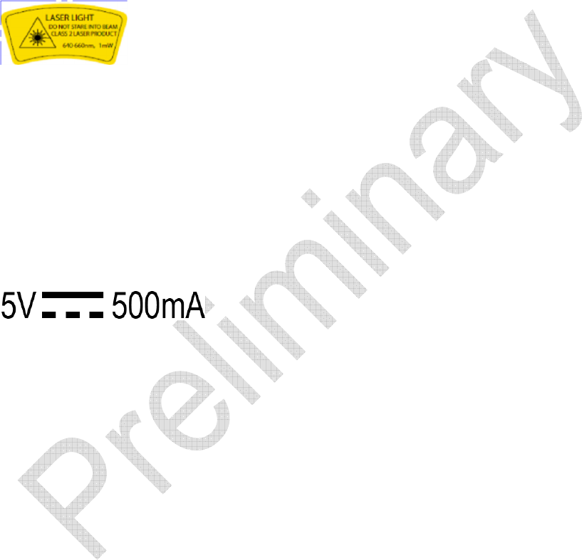
Appendix H – Laser Safety
CAUTION: This device emits CDRH/IEC Class 2 laser light. Do not stare into beam.
This product contains a red (640-660nm), 1mW class 2 Laser Aimer. It conforms to the
requirements of IEC/EN 60825-1 (2001) under all operating conditions and meets the
accessible radiation limits (AELs) required for a Class 2 laser product.
Appendix I – Power Input
Base input power is 5V DC @ 500mA. Power provided through a standard USB
cable attached to base.

56
9/10/15