JADAK a business unit of Novanta MERCURY3 RF ID Reader User Manual
Trimble Navigation Limited RF ID Reader Users Manual
UserManual.wiki
>
JADAK a business unit of Novanta
>
MERCURY3 User Manual
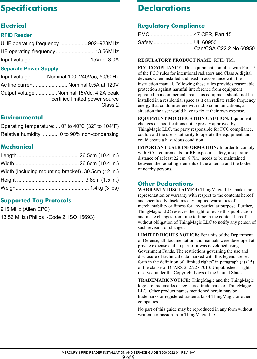
Users Manual
Navigation menu
Upload a User Manual
Namespaces
Wiki Guide
HTML
PDF
Info
Views
User Manual
Discussion / Help
Navigation