JADAK a business unit of Novanta MERCURY6E RFID Module User Manual M6eHardwareGuide
Trimble Navigation Limited RFID Module M6eHardwareGuide
UserManual.wiki
>
JADAK a business unit of Novanta
>
MERCURY6E User Manual
>
Manual
Contents
1.
Manual
2.
User manual_TM_M6e-UG_Jan_2019.pdf
Manual
Navigation menu
Upload a User Manual
Namespaces
Wiki Guide
HTML
PDF
Info
Views
User Manual
Discussion / Help
Navigation

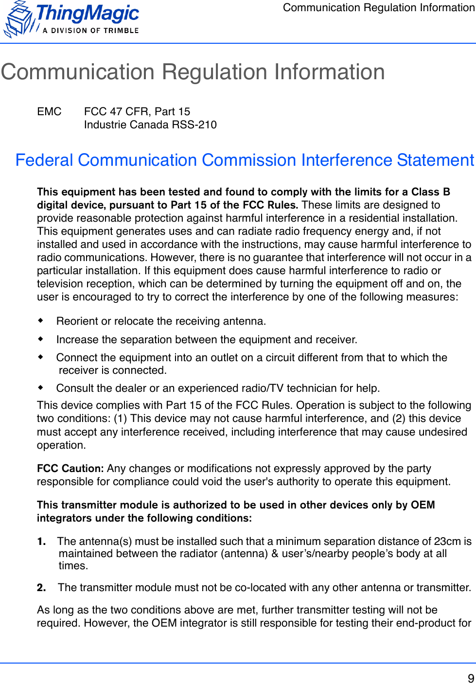


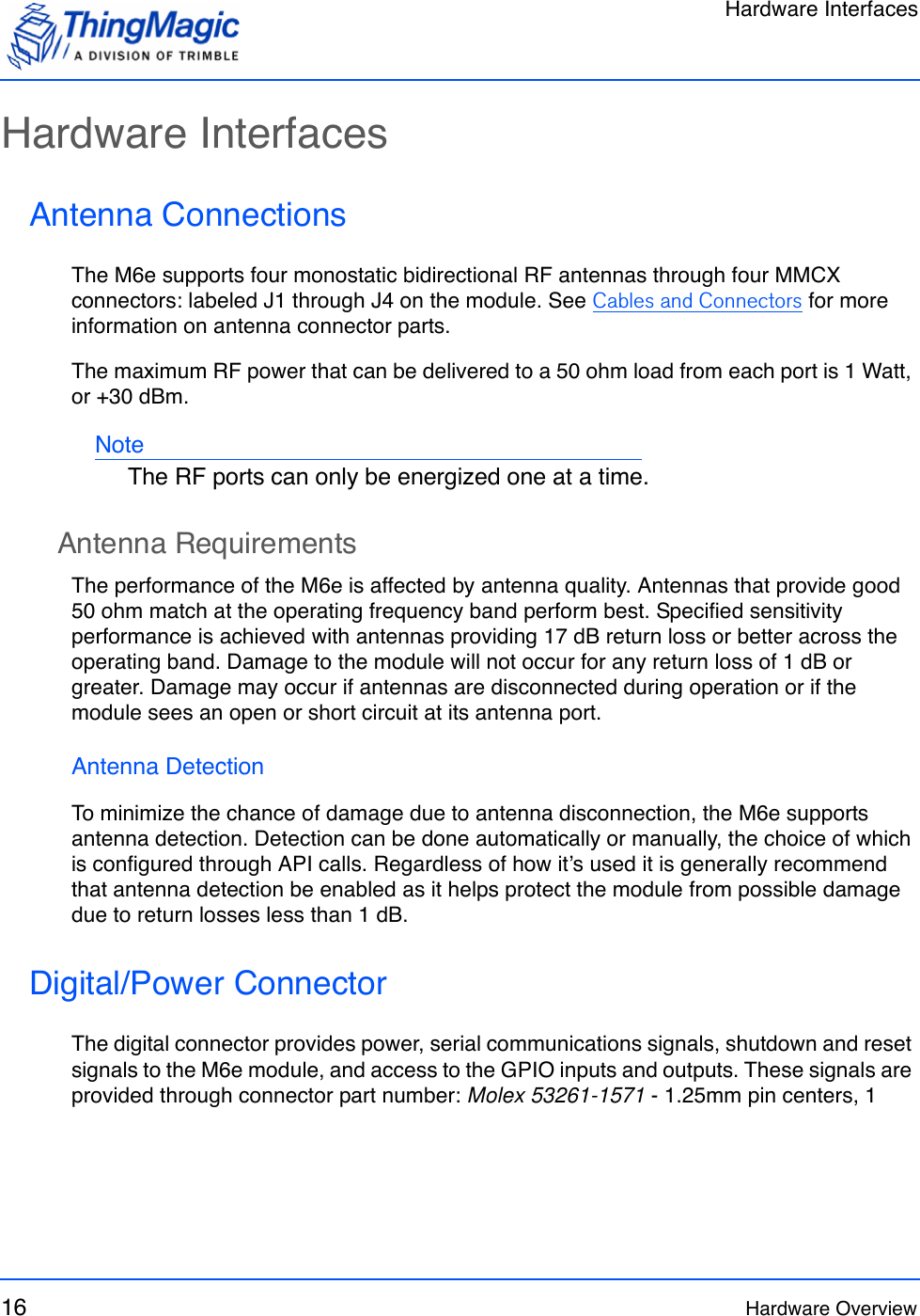
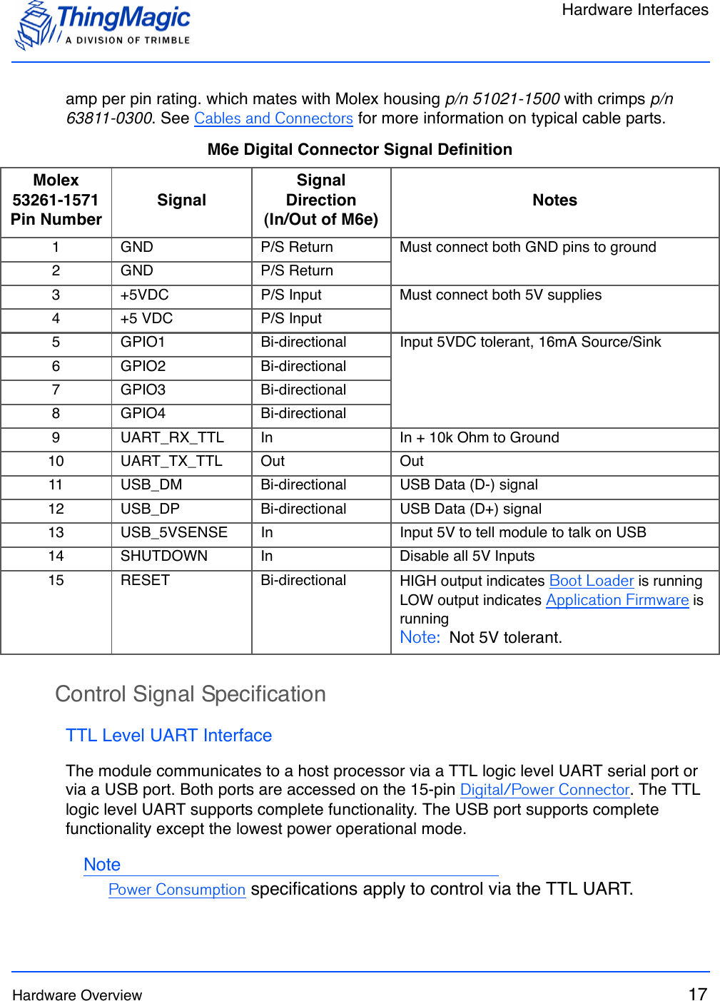
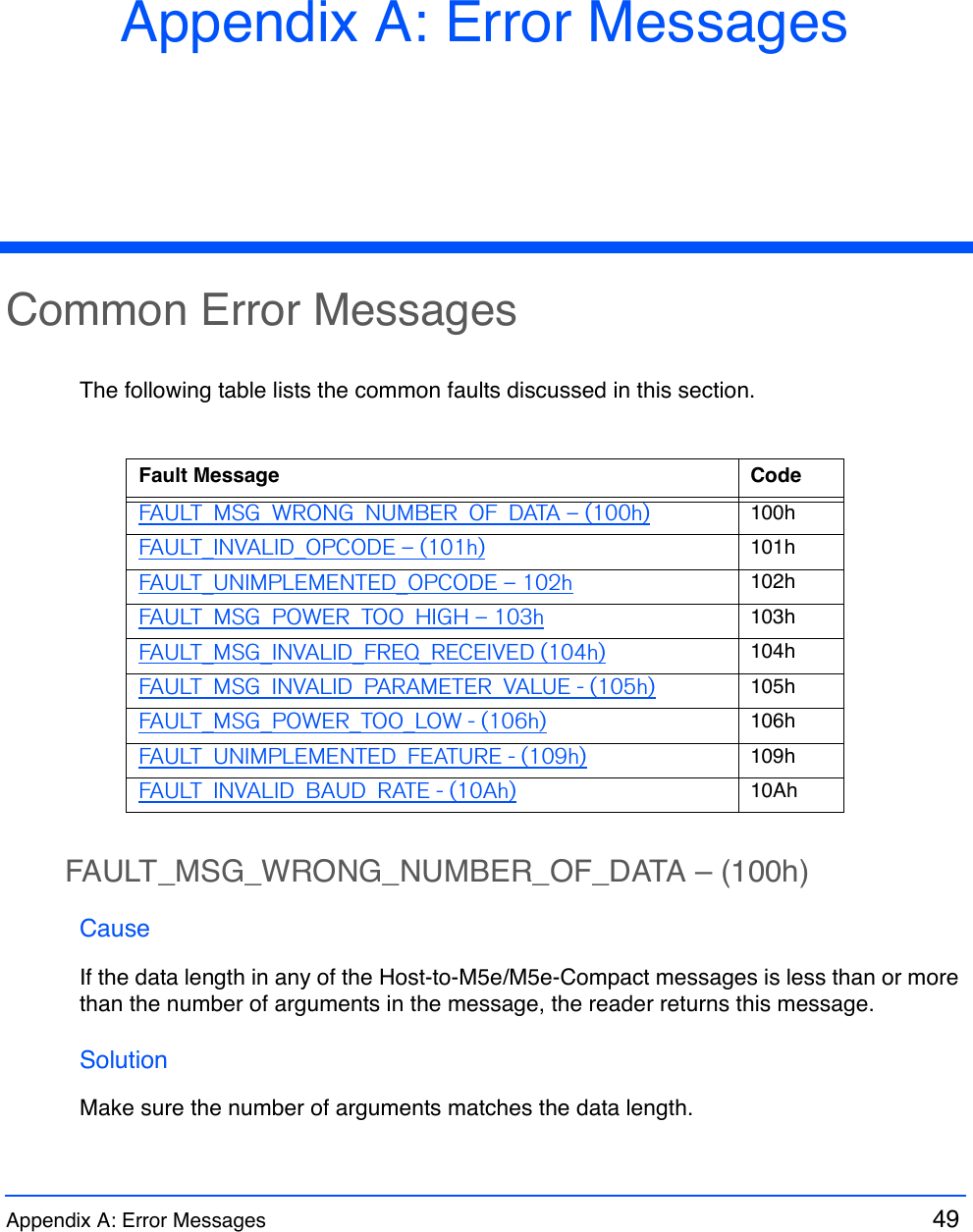
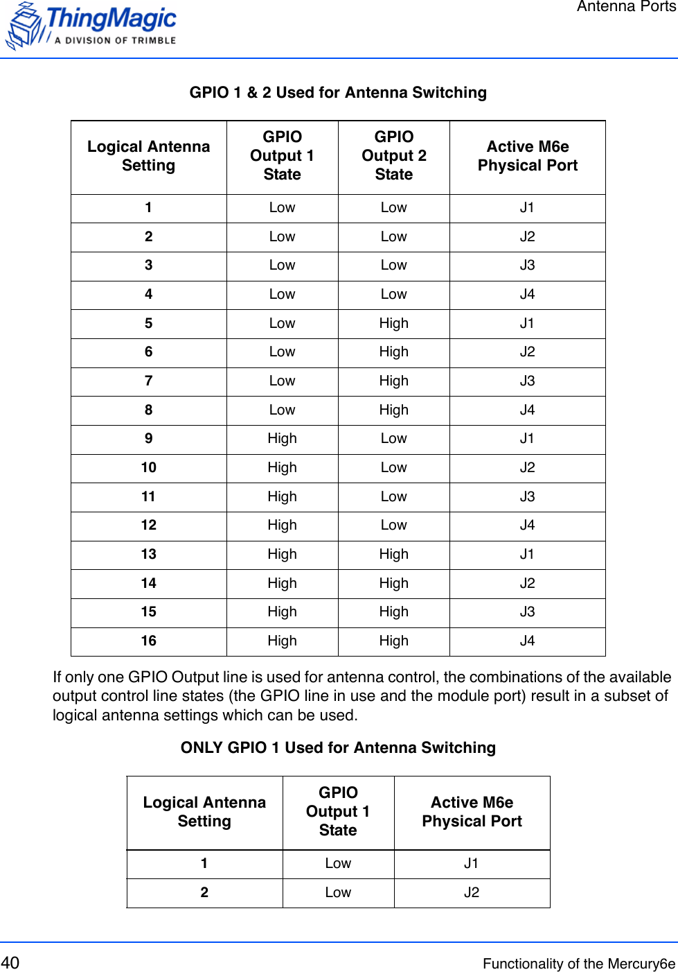
![Assembly Information24 Hardware OverviewAssembly InformationCables and ConnectorsThe following are the cables and connectors used in the M6e Developer’s Kit interface board:Digital InterfaceThe cable assembly used consists of the following parts: 2 Connector Shells [Molex 51021-1500] with 15 Crimp Contacts each [Molex 50079-8100] 1 Wire (#28 AWG 7x36 - Black, Teflon) for Pin 1 connection [Alpha 284/7-2] 14 Wires (#28 AWG 7x36 - White, Teflon) for other connections [Alpha 284/7-1]NotePin numbers and assignments are shown in the M6e Digital Connector Signal Definition table.AntennasThe cable assembly used to connect the “external” RP-TNC connectors on the M6e Devkit to the M6e MMCX connectors consists of the following parts: 1 Reverse TNC Bulkhead Jack Connector 1 LMR-100A Coaxial Cable 1 MMCX Right Angle Plug Connector](https://usermanual.wiki/JADAK-a-business-unit-of-Novanta/MERCURY6E.Manual/User-Guide-1398119-Page-24.png)

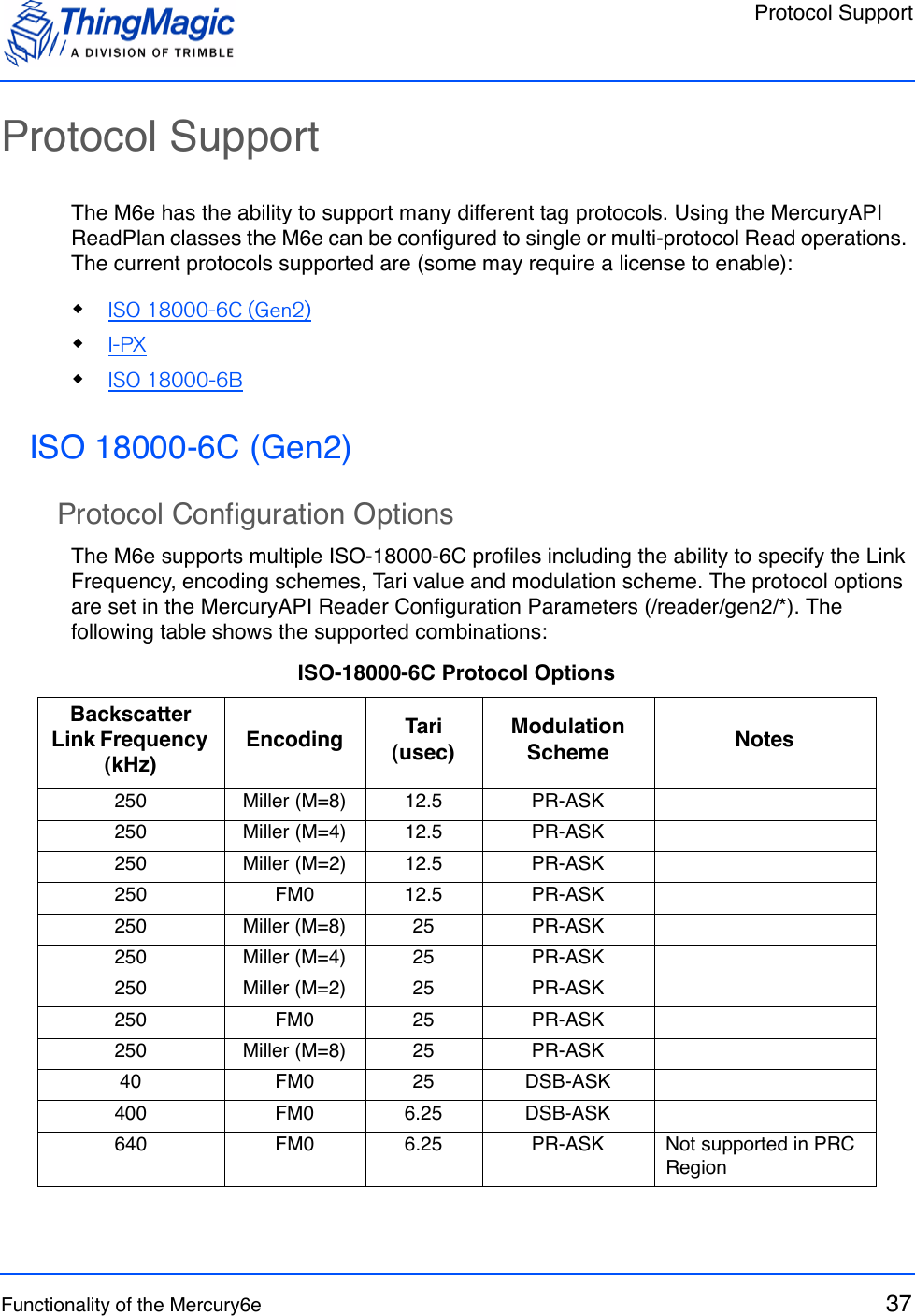
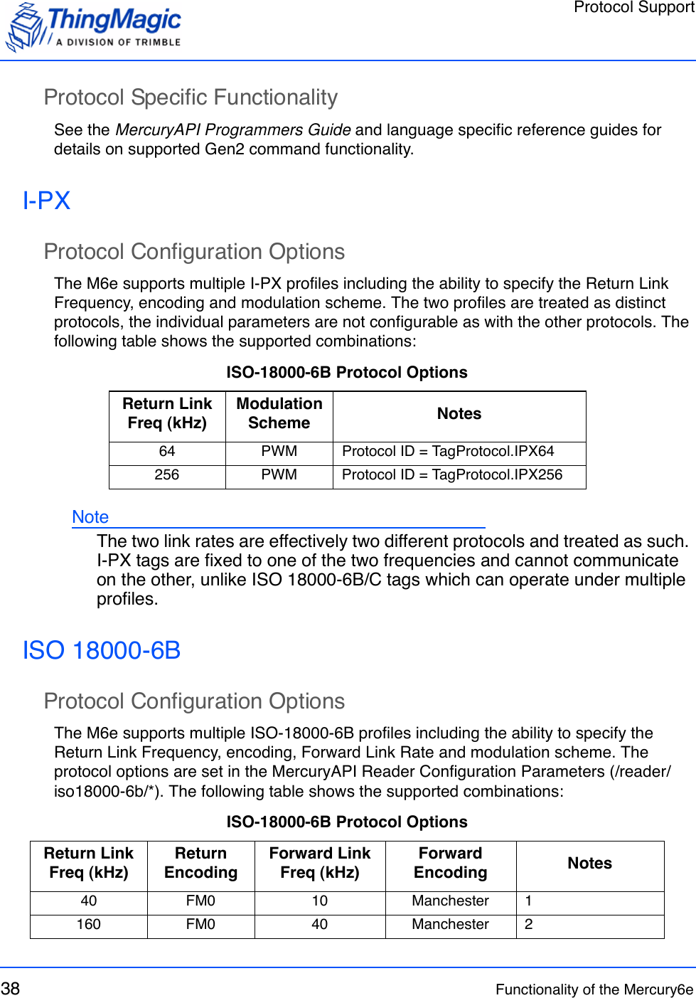
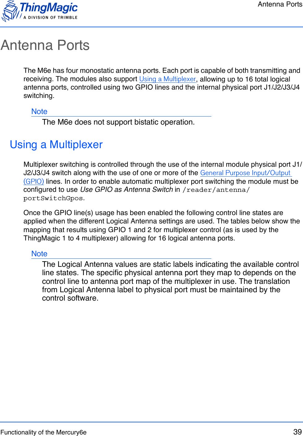
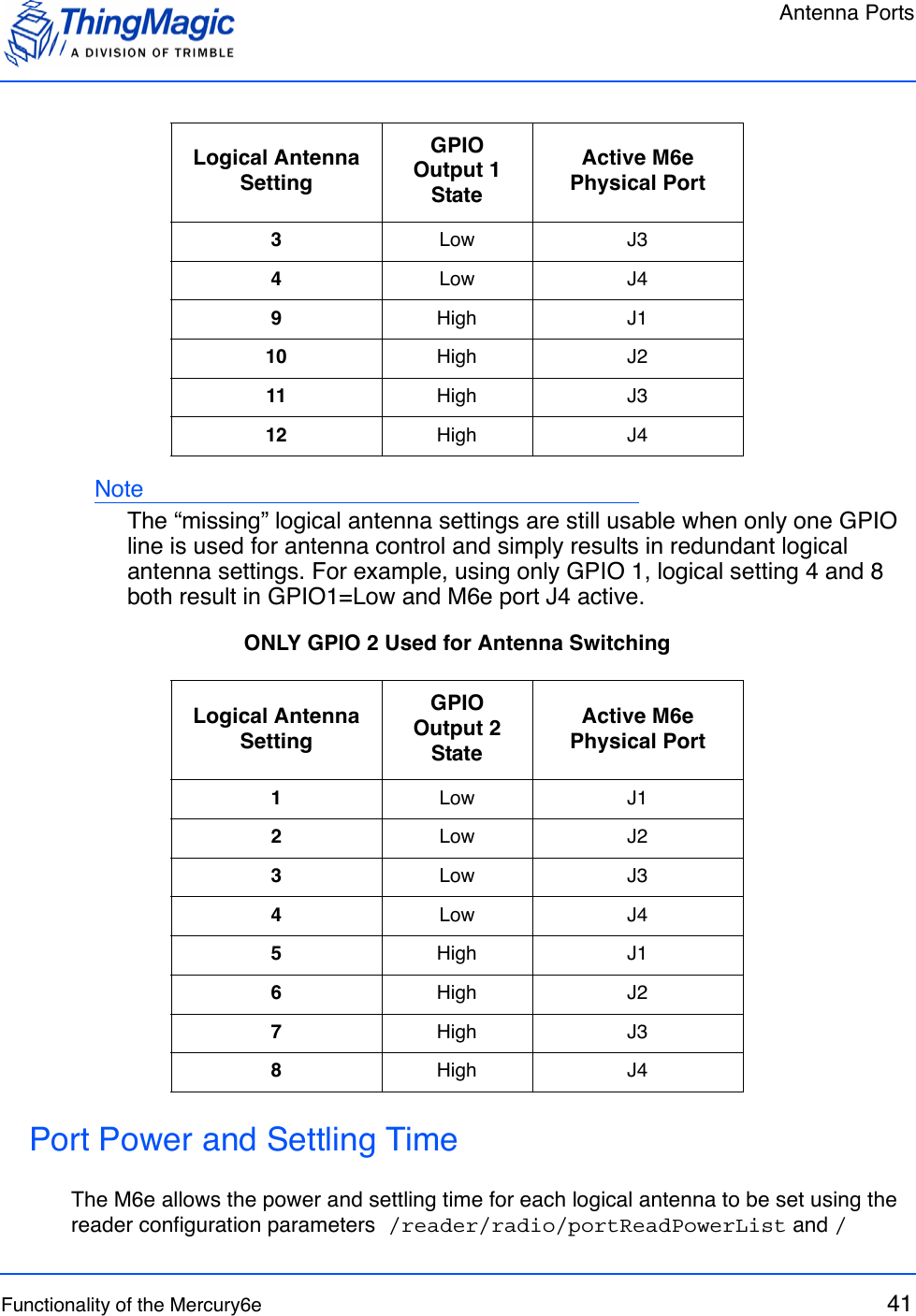
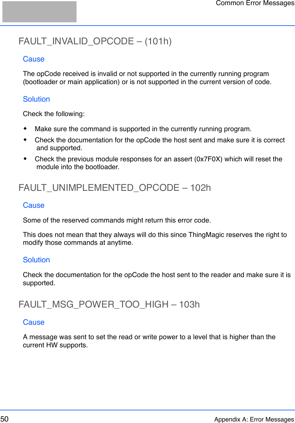
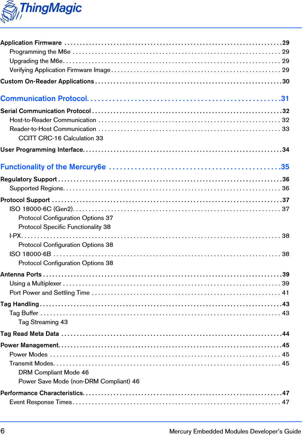
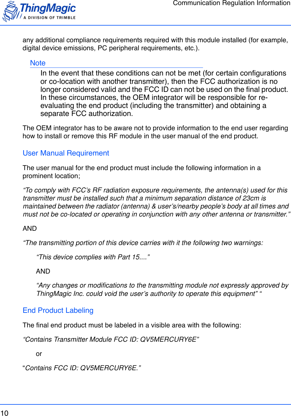
![Tag HandlingFunctionality of the Mercury6e 43Tag HandlingWhen the M6e performs inventory operations (MercuryAPI Read commands) data is stored in a Tag Buffer until retrieved by the client application, or streamed directly to the client if operating in Streaming mode [Not Yet Implemented]. Tag BufferThe M6e uses a dynamic buffer that depends on EPC length and quantity of data read. As a rule of thumb it can store a maximum of 1024 96-bit EPC tags in the TagBuffer at a time. Since the M6e supports streaming of read results the buffer limit is, typically, not an issue. Each tag entry consists of a variable number of bytes and consists of the following fields:The Tag buffer acts as a First In First Out (FIFO) — the first Tag found by the reader is the first one to be read out. Tag St r eam ingWhen reading tags during inventory operations (MercuryAPI Reader.Read() and Reader.StartReading()) by default the M6e “streams” the tag results back to the host processor. This means that tags are pushed out of the buffer as soon as they are processed by the M6e and put into the buffer. The buffer is put into a circular mode that keeps the buffer from filling. This allows for the M6e to perform continuous search operations without the need to periodically stop reading and fetch the contents of the buffer. Aside from not seeing “down time” when performing a read operation this behavior is essentially invisible to the user as all tag handling is done by the MercuryAPI.Tag Buffer EntryTotal Entry Size Field Size Description68 bytes (Max EPC Length = 496bits)EPC Length2 bytes Indicates the actual EPC length of the tag read. Cannot exceed the Max EPC length setting.PC Word 2 bytes Contains the Protocol Control bits for the tag.EPC 62 bytes Contains the tag’s EPC value padded with trailing zeros if the size is less than the Max EPC Length size.Tag CRC 2 bytes The tag’s CRC.Tag Read Meta Data](https://usermanual.wiki/JADAK-a-business-unit-of-Novanta/MERCURY6E.Manual/User-Guide-1398119-Page-43.png)
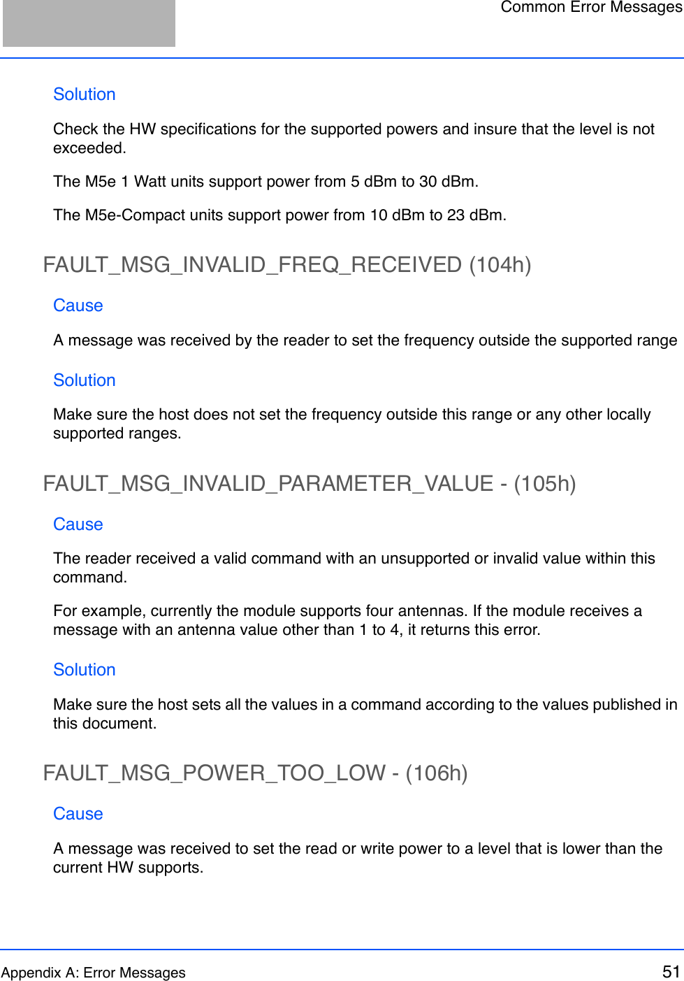
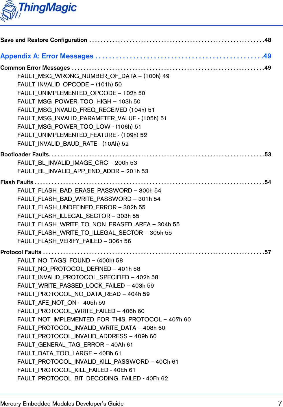
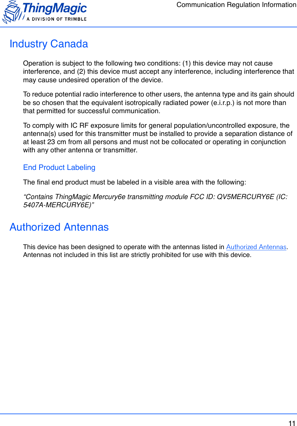
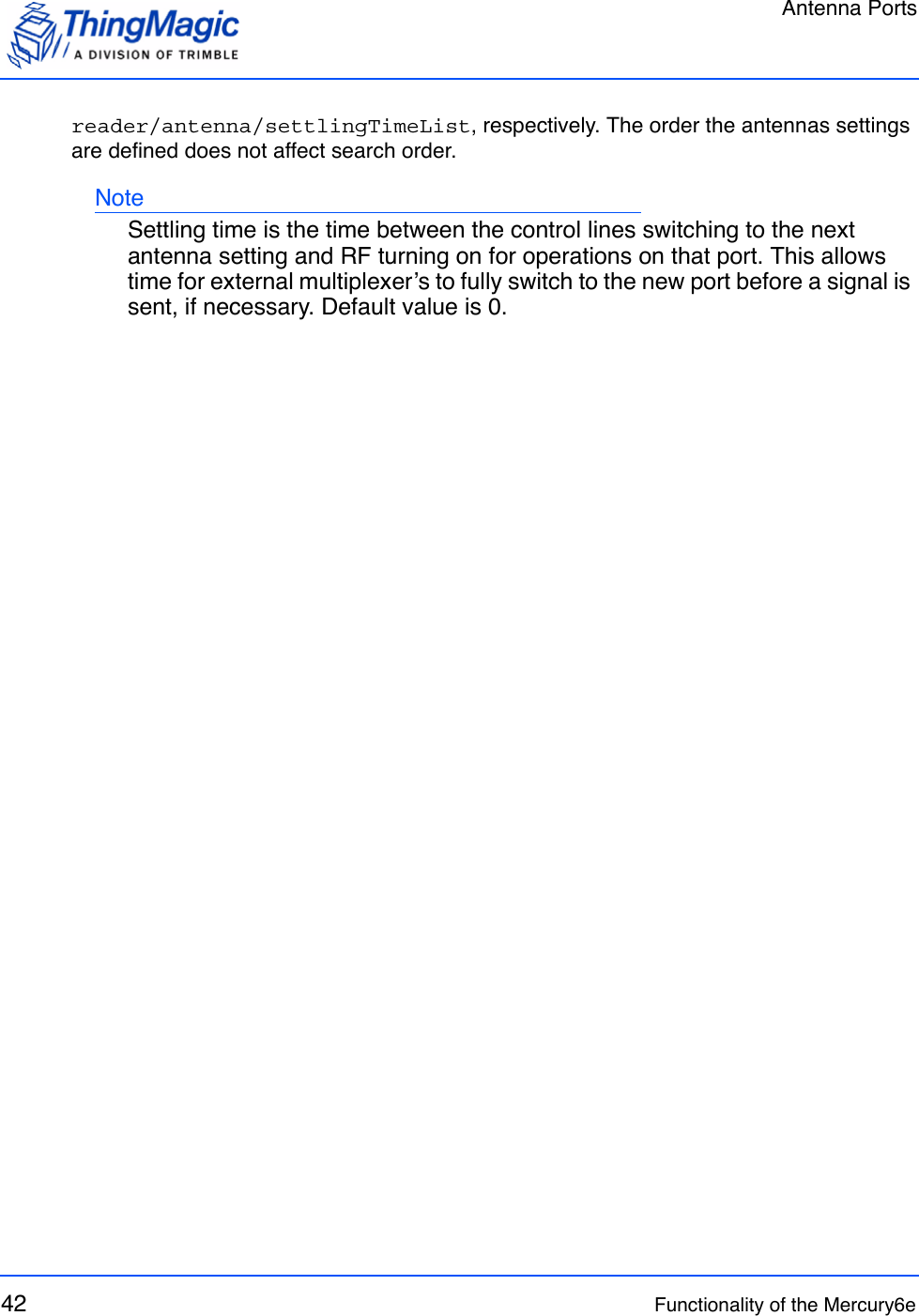
![Tag Read Meta Data44 Functionality of the Mercury6eTag Read Meta DataIn addition to the tag EPC ID resulting from M6e inventory operation each TagReadData (see MercuryAPI for code details) contains meta data about how, where and when the tag was read. The specific meta data available for each tag read is as follows:Tag Read Meta DataMeta Data Field DescriptionAntenna ID The antenna on with the tag was read. If the same tag is read on more than one antenna there will be a tag buffer entry for each antenna on which the tag was read. When Using a Multi-plexer, if appropriately configured, the Antenna ID entry will contain the logical antenna port of the tag read.Read Count The number of times the tag was read on [Antenna ID]. Timestamp The time the tag was read, relative to the time the command to read was issued, in milliseconds. If the Tag Read Meta Data is not retrieved from the Tag Buffer between read commands there will be no way to distinguish order of tags read with dif-ferent read command invocations. Tag Data When reading an embedded TagOp is specified for a Read-Plan the TagReadData will contain the first 4 bytes of data returned for each tag. Note: Tags with the same TagID but different Tag Data can be considered unique and each get a Tag Buffer entry if set in the reader configuration parameter /reader/tagReadData/uniqueByData. By default it is not.Frequency The frequency on which the tag was readTag Phase Average phase of tag response in degreesLQI/RSSI The receive signal strength of the tag response in dBm.GPIO Status The signal status (High or Low) of all GPIO pins when tag was read.](https://usermanual.wiki/JADAK-a-business-unit-of-Novanta/MERCURY6E.Manual/User-Guide-1398119-Page-44.png)