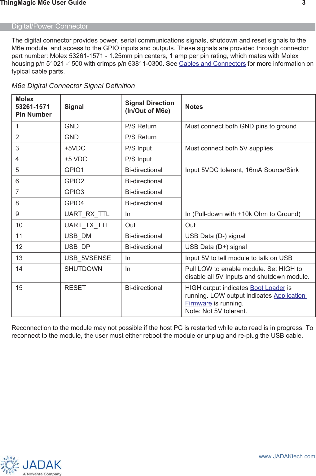
JADAK a business unit of Novanta MERCURY6E RFID Module User Manual ThingMagic M6e User Guide
JADAK, a business unit of Novanta Corporation RFID Module ThingMagic M6e User Guide
Contents
- 1. Manual
- 2. User manual_TM_M6e-UG_Jan_2019.pdf
User manual_TM_M6e-UG_Jan_2019.pdf

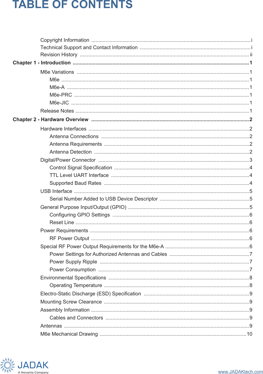
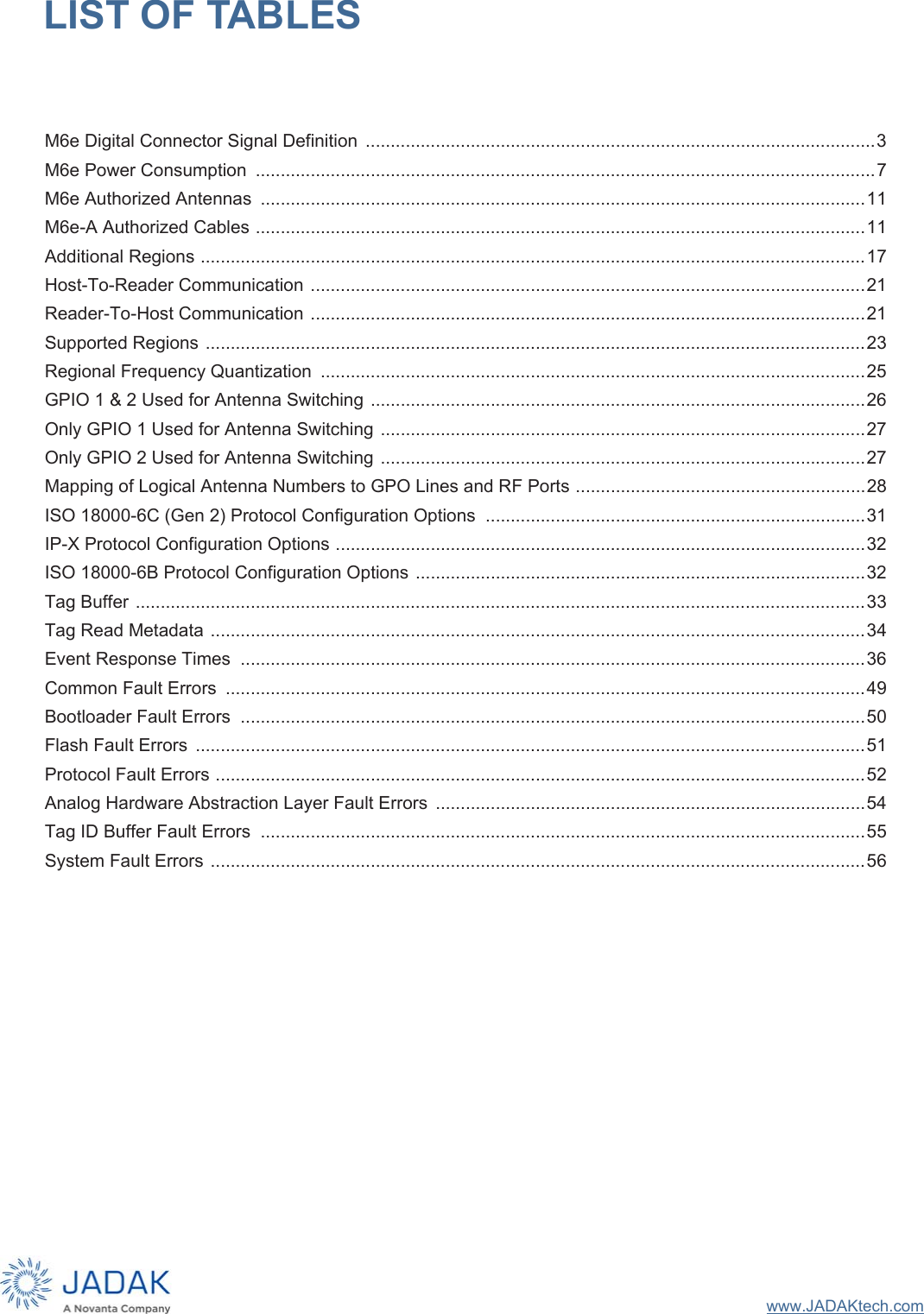
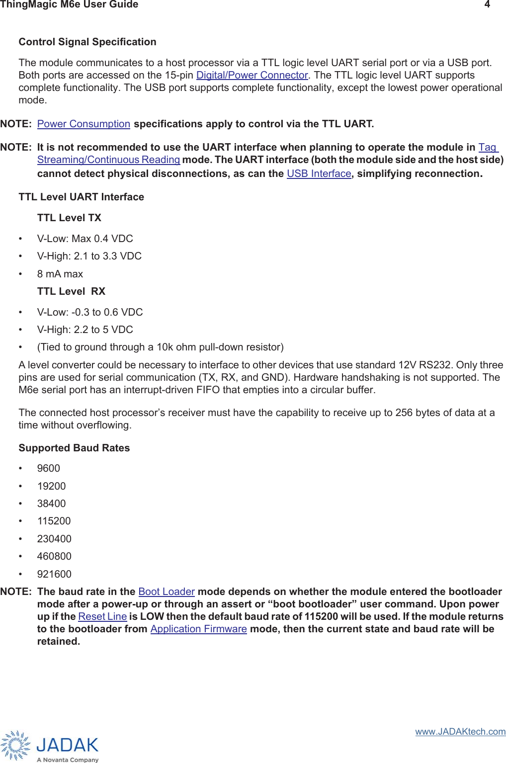
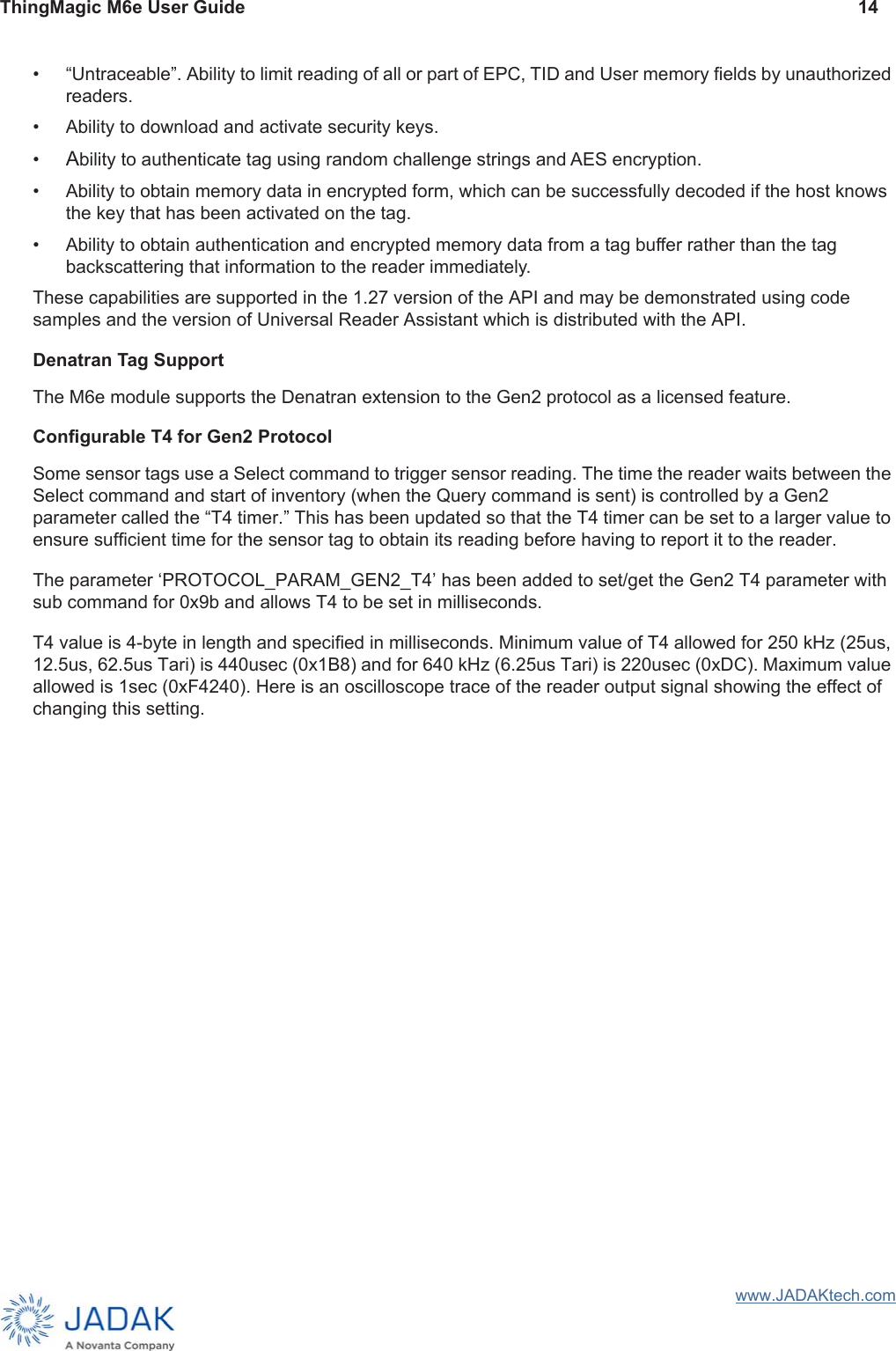
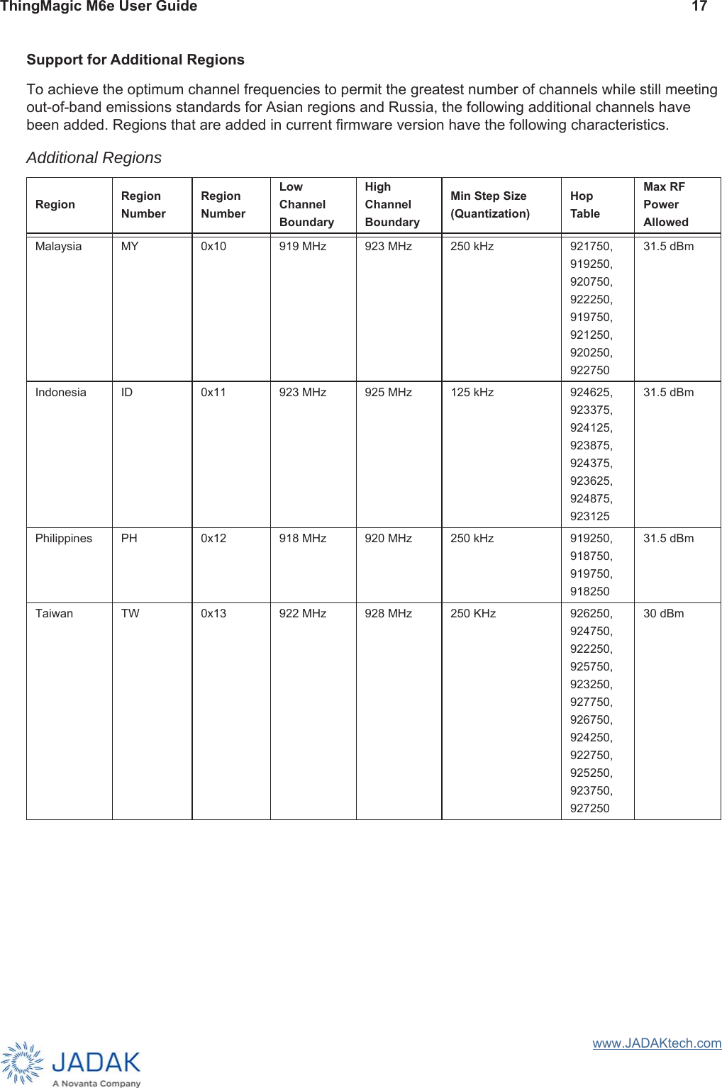
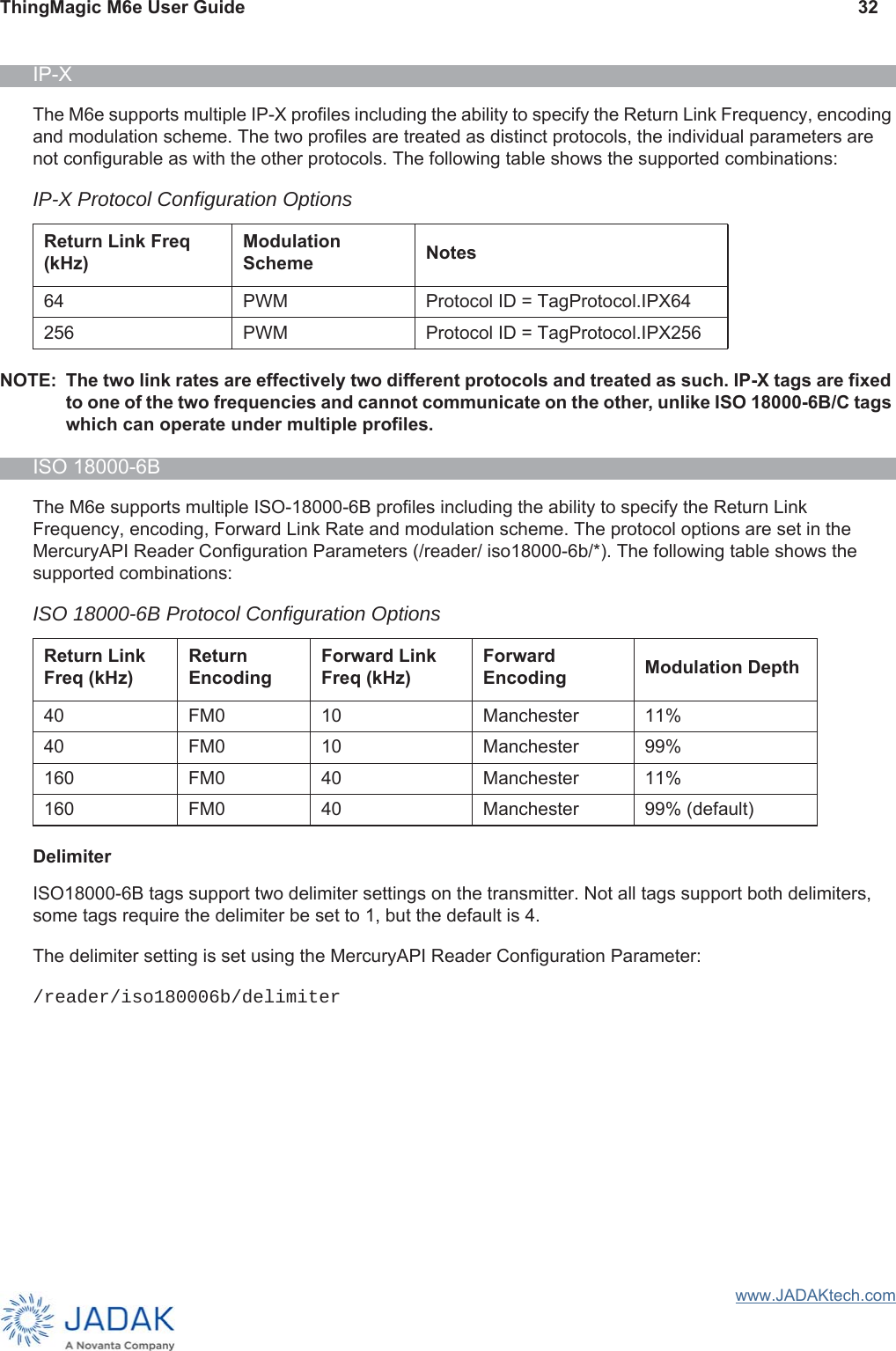
![ThingMagic M6e User Guide 9www.JADAKtech.comElectro-Static Discharge (ESD) SpecificationIEC-61000-4-2 and MIL-883 3015.7 discharges direct to operational antenna port tolerates max 1200 volt pulse.NOTE: Survival level varies with antenna return loss and antenna characteristics. See ElectroStatic Discharge (ESD) Considerations for methods to increase ESD tolerances.Mounting Screw ClearanceThe M6e requires clearance for #2-56 or 2.5mm socket head screws in 4 places.Assembly InformationCables and ConnectorsThe following are the cables and connectors used in the M6e Developer’s Kit interface board:Digital InterfaceThe cable assembly used consists of the following parts:• 2 Connector Shells [Molex 51021-1500] with 15 Crimp Contacts each [Molex 50079-8100]• 1 Wire (#28 AWG 7x36 - Black, Teflon) for Pin 1 connection [Alpha 284/7-2]• 14 Wires (#28 AWG 7x36 - White, Teflon) for other connections [Alpha 284/7-1]NOTE: Pin numbers and assignments are shown in the M6e Digital Connector Signal Definition table.AntennasThe cable assembly used to connect the “external” RP-TNC connectors on the M6e Development kit to the M6e MMCX connectors consists of the following parts:• 1 Reverse TNC Bulkhead Jack Connector• 1 LMR-100A Coaxial Cable• 1 MMCX Right Angle Plug ConnectorWarning: The M6e antenna ports may be susceptible to damage from Electrostatic Discharge (ESD). Equipment failure can result if the antenna or communication ports are subjected to ESD. Standard ESD precautions should be taken during installation and operation to avoid static discharge when handling or making connections to the M6e reader antenna or communication ports. Environmental analysis should also be performed to ensure static is not building up on and around the antennas, possibly causing discharges during operation.](https://usermanual.wiki/JADAK-a-business-unit-of-Novanta/MERCURY6E.User-manual-TM-M6e-UG-Jan-2019-pdf/User-Guide-4163410-Page-17.png)
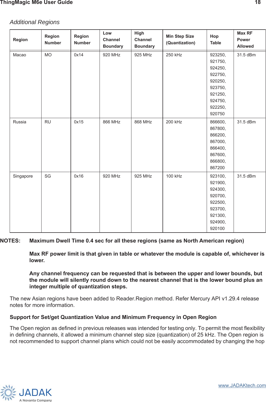
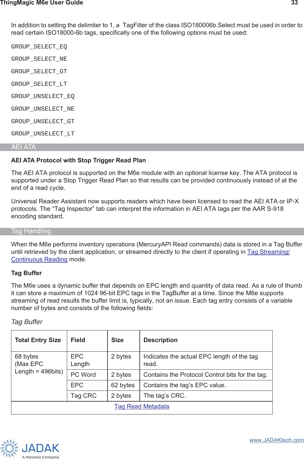
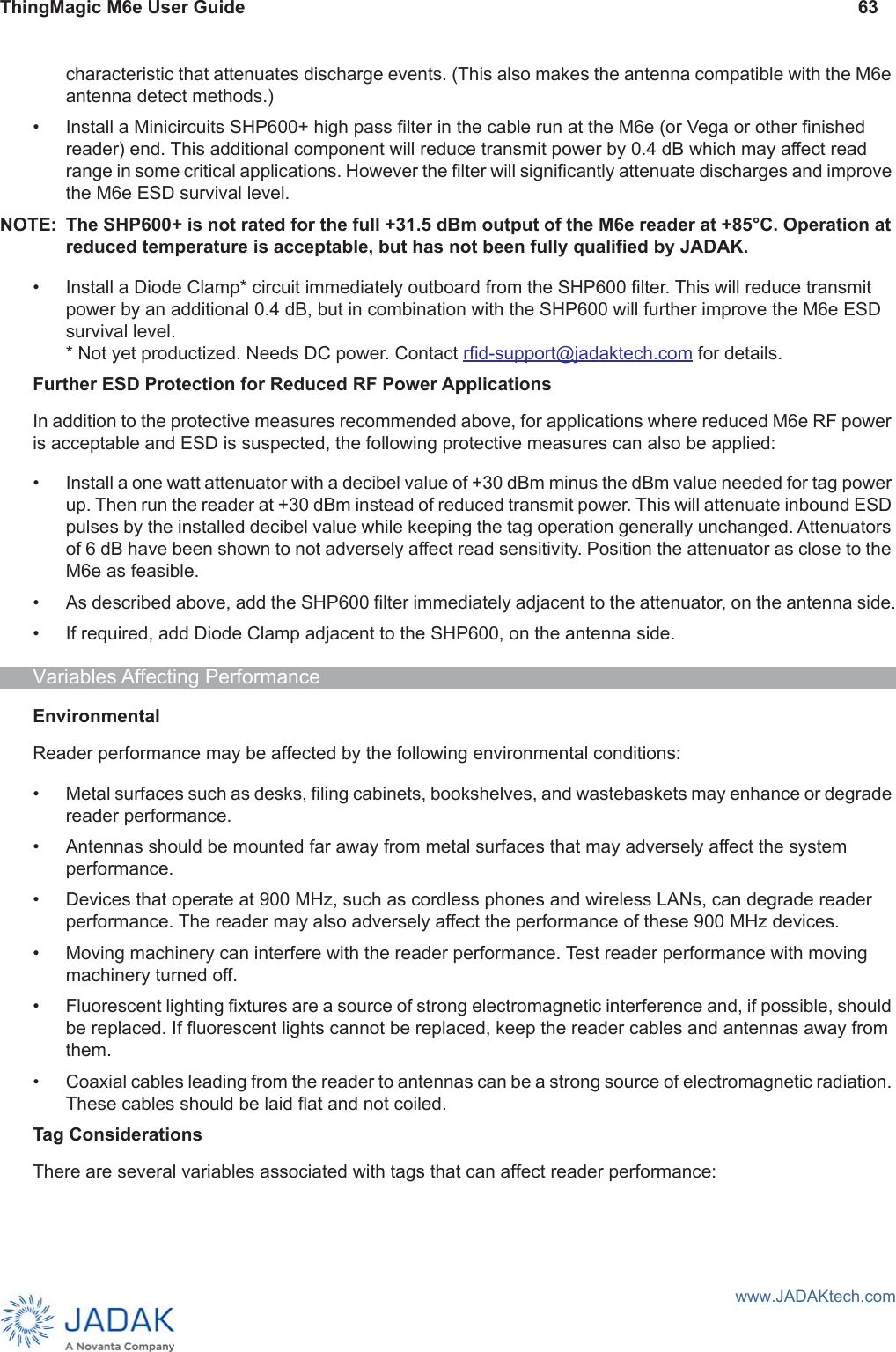
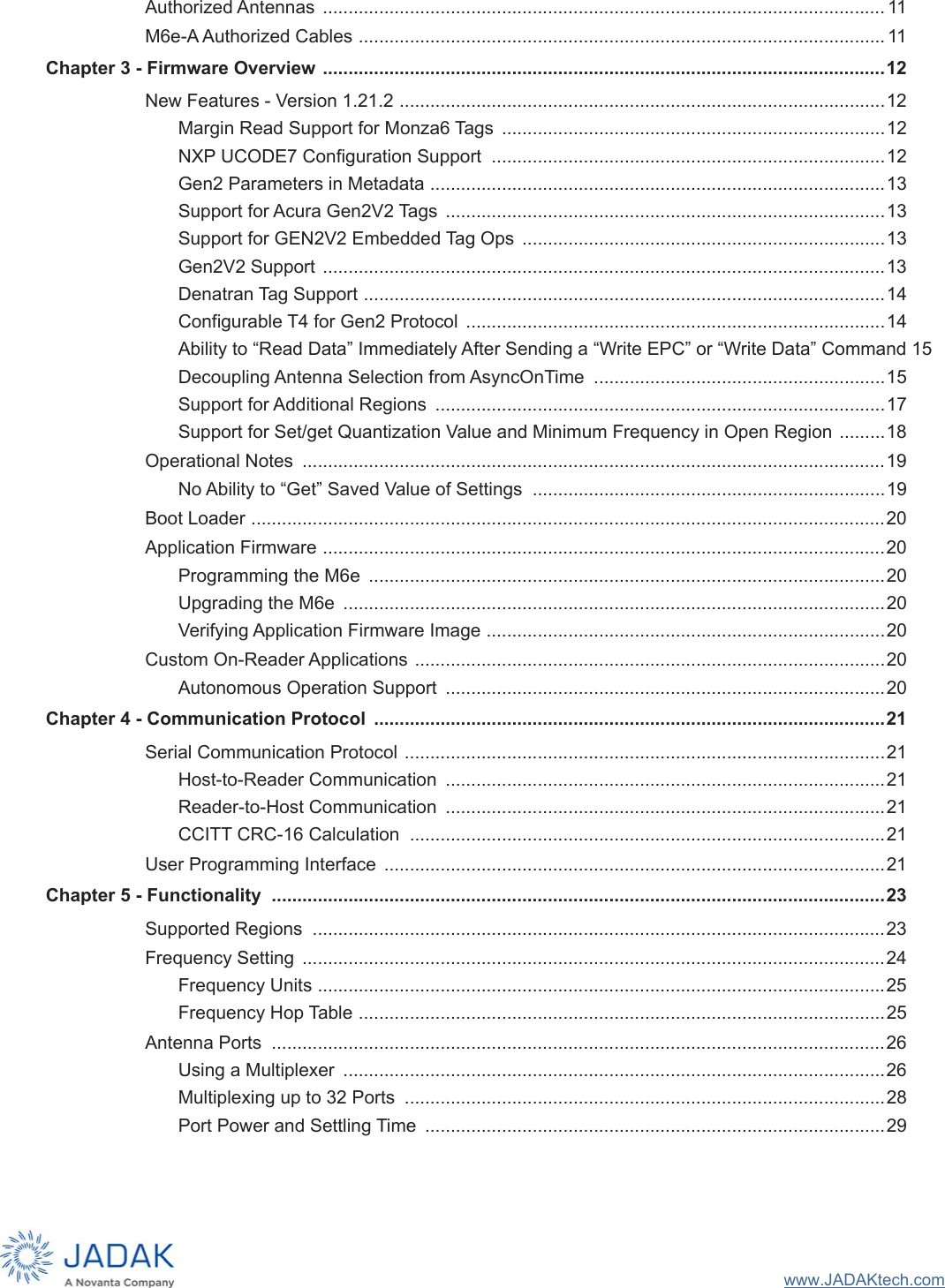
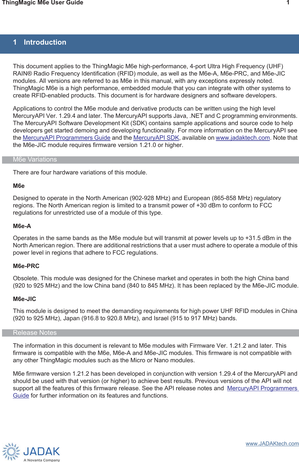
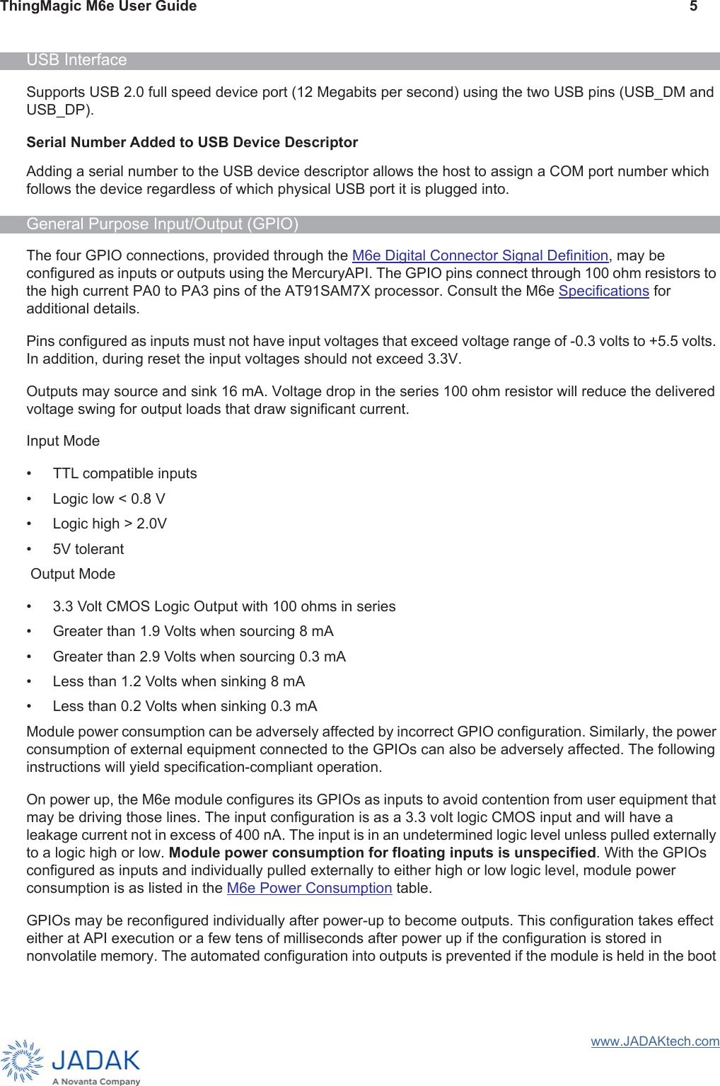
![ThingMagic M6e User Guide 34www.JADAKtech.comThe Tag buffer acts as a First In First Out (FIFO) — the first Tag found by the reader is the first one to be read out. Tag Streaming/Continuous ReadingWhen reading tags during asynchronous inventory operations (MercuryAPI Reader.StartReading()) using an /reader/read/asyncOffTime=0 the M6e “streams” the tag results back to the host processor. This means that tags are pushed out of the buffer as soon as they are processed by the M6e and put into the buffer. The buffer is put into a circular mode that keeps the buffer from filling. This allows for the M6e to perform continuous search operations without the need to periodically stop reading and fetch the contents of the buffer. Aside from not seeing “down time” when performing a read operation, this behavior is essentially invisible to the user as all tag handling is done by the MercuryAPI. NOTE: It is recommended the USB Interface be used when operating the M6e in continuous reading mode. When the TTL Level UART Interface is used, it is not possible for the module to detect a broken communications interface connection and stop streaming the tag results.Tag Read MetadataIn addition to the tag EPC ID resulting from M6e inventory operation each TagReadData (see MercuryAPI for code details) contains metadata about how, where and when the tag was read. The specific metadata available for each tag read is as follows:Tag Read MetadataMetadata Field DescriptionAntenna ID The antenna on with the tag was read. If the same tag is read on more than one antenna there will be a tag buffer entry for each antenna on which the tag was read. When Using a Multiplexer, if appropriately configured, the Antenna ID entry will contain the logical antenna port of the tag read.Read Count The number of times the tag was read on [Antenna ID]. Timestamp The time the tag was read, relative to the time the command to read was issued, in milliseconds. If the Tag Read Metadata is not retrieved from the Tag Buffer between read commands there will be no way to distinguish order of tags read with different read command invocations. Tag Data When reading an embedded TagOp is specified for a ReadPlan the TagReadData will contain the first 128 words of data returned for each tag. NOTE: Tags with the same TagID but different Tag Data can be considered unique and each get a Tag Buffer entry if set in the reader configuration parameter /reader/tagReadData/ uniqueByData. By default it is not.Frequency The frequency on which the tag was read.Tag Phase Average phase of tag response in degrees (0°-180°).LQI/RSSI The receive signal strength of the tag response in dBm.GPIO Status The signal status (High or Low) of all GPIO pins when tag was read.](https://usermanual.wiki/JADAK-a-business-unit-of-Novanta/MERCURY6E.User-manual-TM-M6e-UG-Jan-2019-pdf/User-Guide-4163410-Page-42.png)
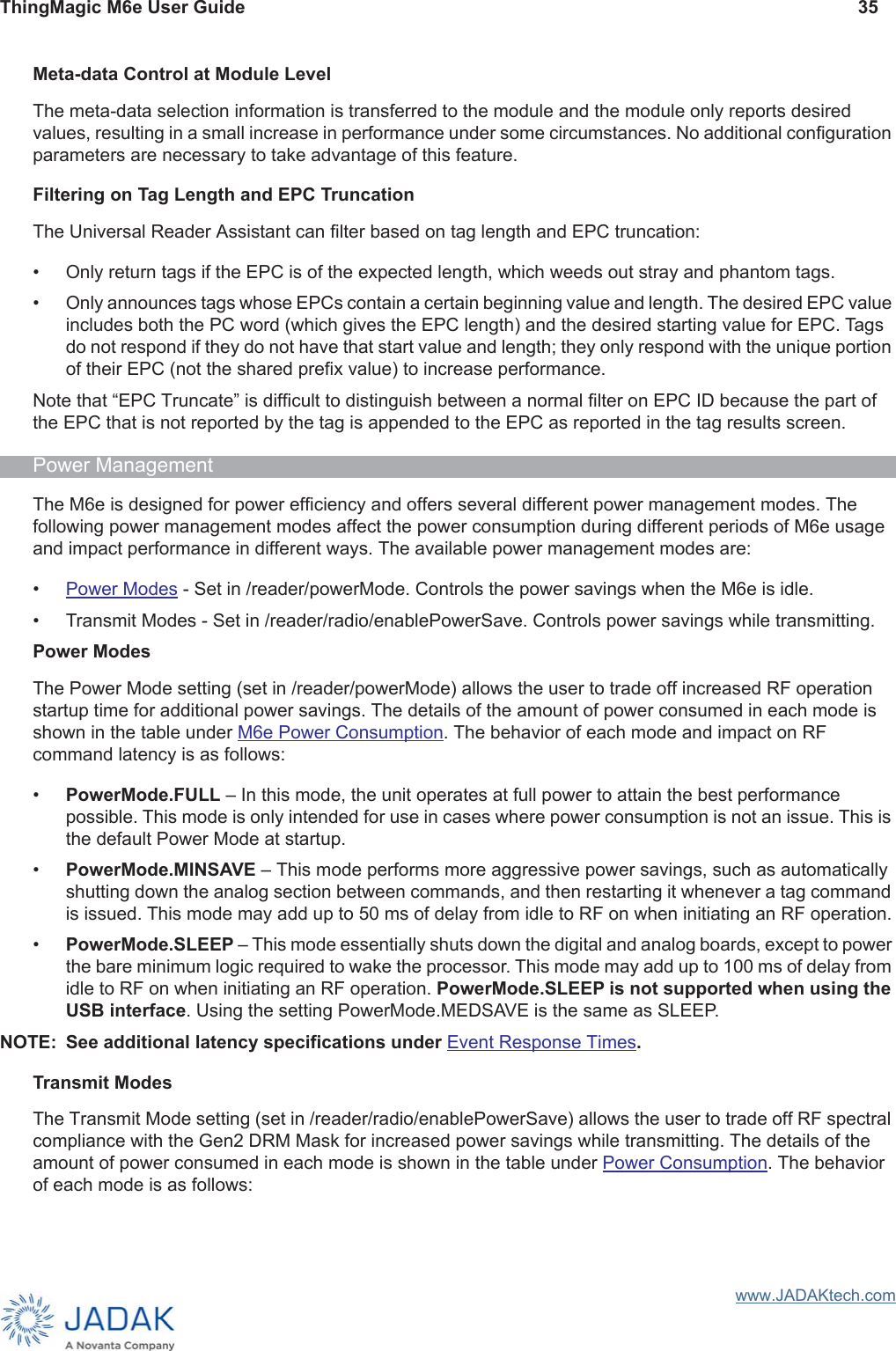


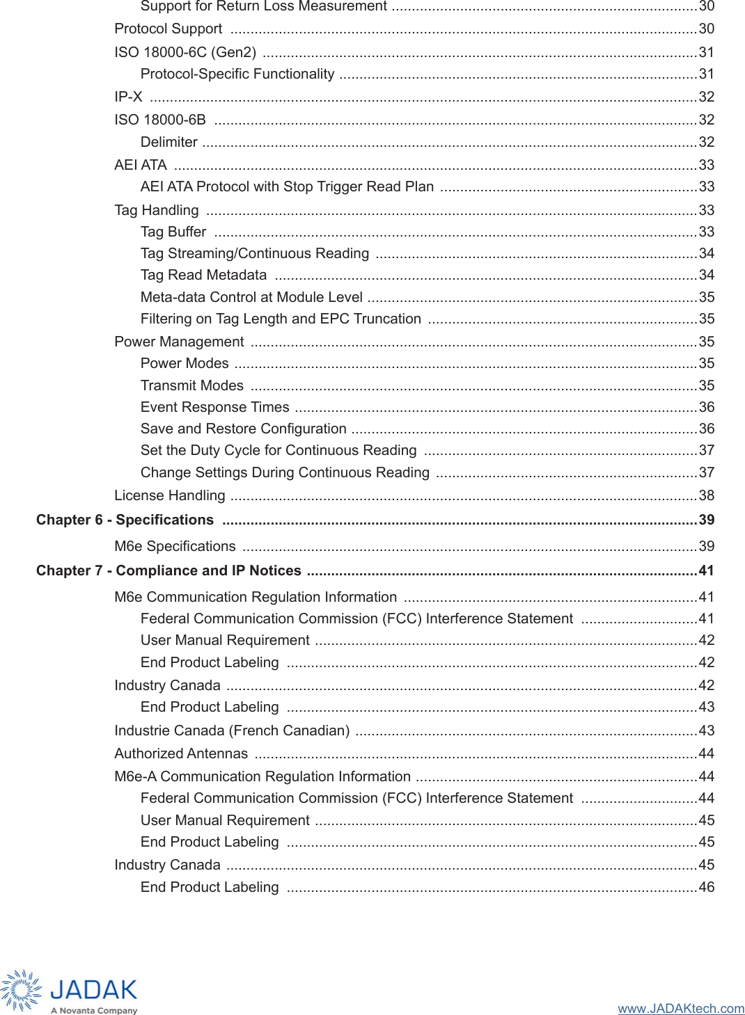
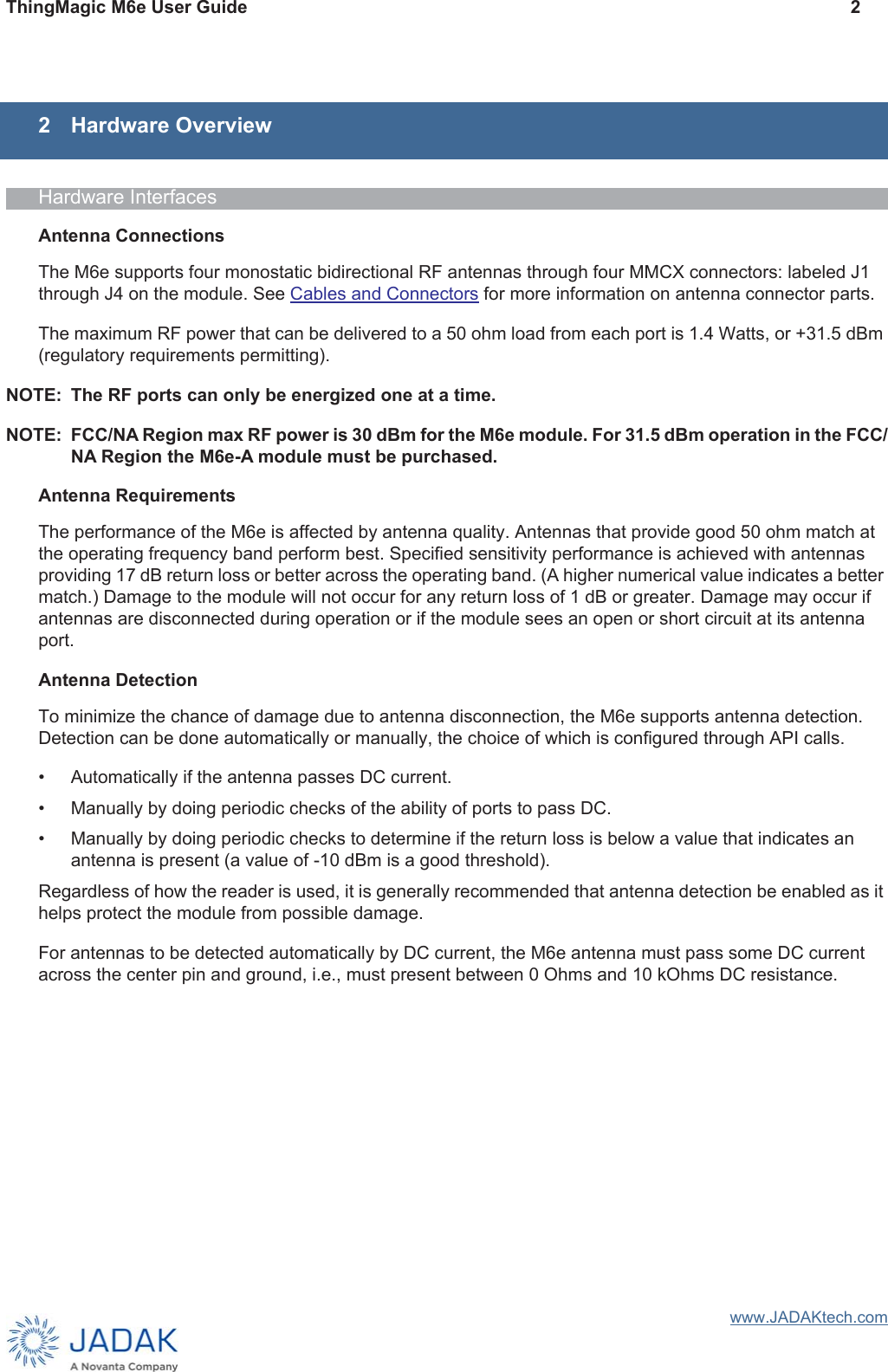
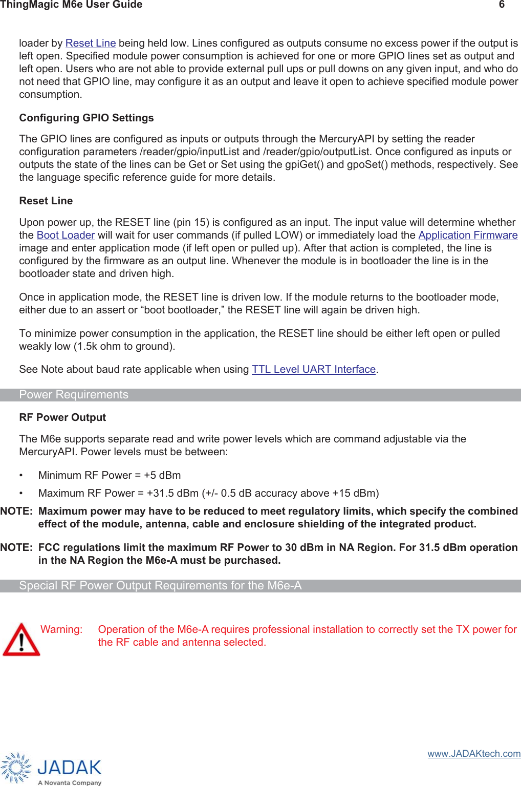
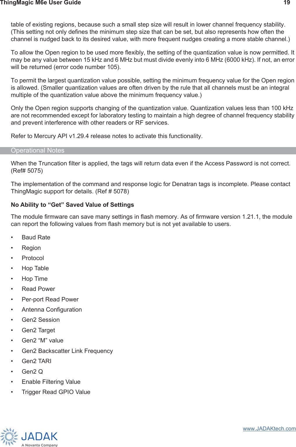
![ThingMagic M6e User Guide 59www.JADAKtech.comJump pins OUT to GPIO# to connect M6e GPIO lines to output LEDs. Jump pins IN to GPIO# to connect M6e GPIO to corresponding input switches SW[3-6]GPIO#. Make sure GPIO lines are correspondingly configured as input or outputs (see Configuring GPIO Settings).J14Can be used to connect GPIO lines to external circuits. If used jumpers should be removed from J10, J11, J13, J15.J16Jump pins 1 and 2 or 2 and 3 to reset development kit power supply. Same as using switch SW1 except allows for control by external circuit.J17Jump pins 1 and 2 to use the 5V INPUT and GND inputs to provide power. Jump pins 2 and 3 to use the development kitʼs DC power jack and power brick power.J19Jump SHUTDOWN to GND to enable module. While grounded SHUTDOWN pushbutton (SW2) will break circuit and shutdown the M6e. See M6e Digital Connector Signal Definition. AUTO_BOOT controls Reset Line.Development Kit SchematicsAvailable upon request from rfid-support@jadaktech.com.Demo ApplicationA demo application which supports multi-protocol reading and writing is provided in the MercuryAPI SDK package and as a standalone application. Both are available from the www.JADAKtech.com. The executable for this example is included in the MercuryAPI SDK package under /cs/samples/exe/Universal-Reader-Assistant.exe. NOTE: The Universal Reader Assistant included in the MercuryAPI SDK maybe an older revision than the one available for standalone download. See the Readme.txt in /cs/samples/Universal-Reader-Assistant/Universal-ReaderAssistant for usage details. See the MercuryAPI Programmers Guide for details on using the MercuryAPI.Notice on Restricted Use of the Development KitThe Developers Kit (Dev Kit) is intended for use solely by professional engineers for the purpose of evaluating the feasibility of applications.The user’s evaluation must be limited to use within a laboratory setting. This Dev Kit has not been certified for use by the FCC in accordance with Part 15 of the FCC regulations, ETSI, KCC or any other regulatory bodies and may not be sold or given for public use.](https://usermanual.wiki/JADAK-a-business-unit-of-Novanta/MERCURY6E.User-manual-TM-M6e-UG-Jan-2019-pdf/User-Guide-4163410-Page-67.png)