JADAK a business unit of Novanta SM-MN-SH M1-Mini User Manual M1 Mini User Guide 07132018
JADAK, a business unit of Novanta Corporation M1-Mini M1 Mini User Guide 07132018
UserManual.wiki
>
JADAK a business unit of Novanta
>
SM MN SH User Manual
M1-Mini User Guide Rev.pdf
Navigation menu
Upload a User Manual
Namespaces
Wiki Guide
HTML
PDF
Info
Views
User Manual
Discussion / Help
Navigation
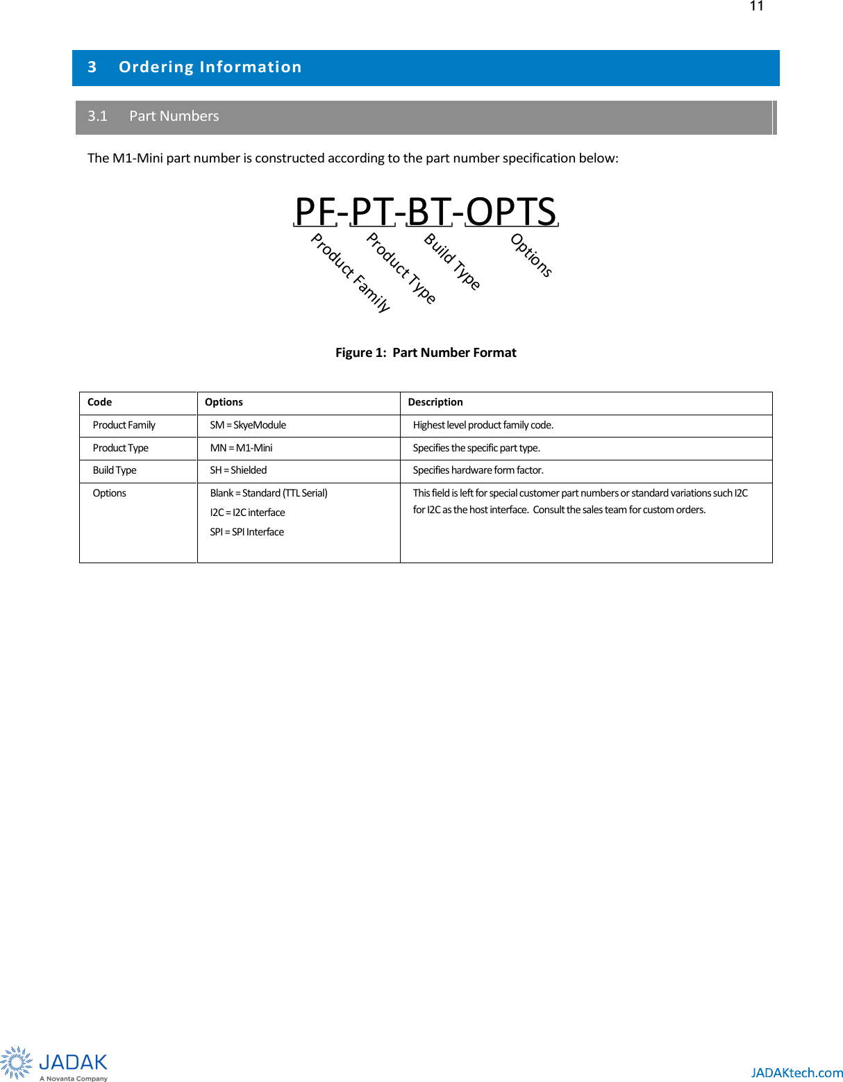
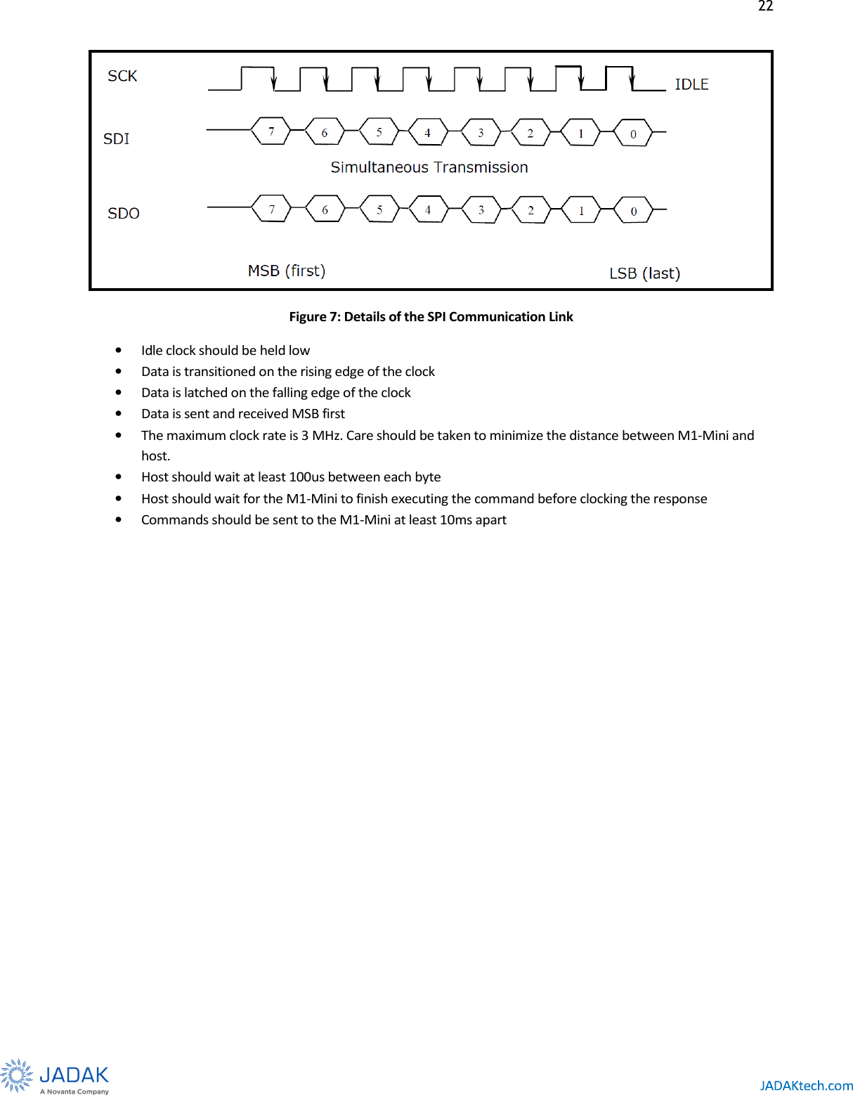
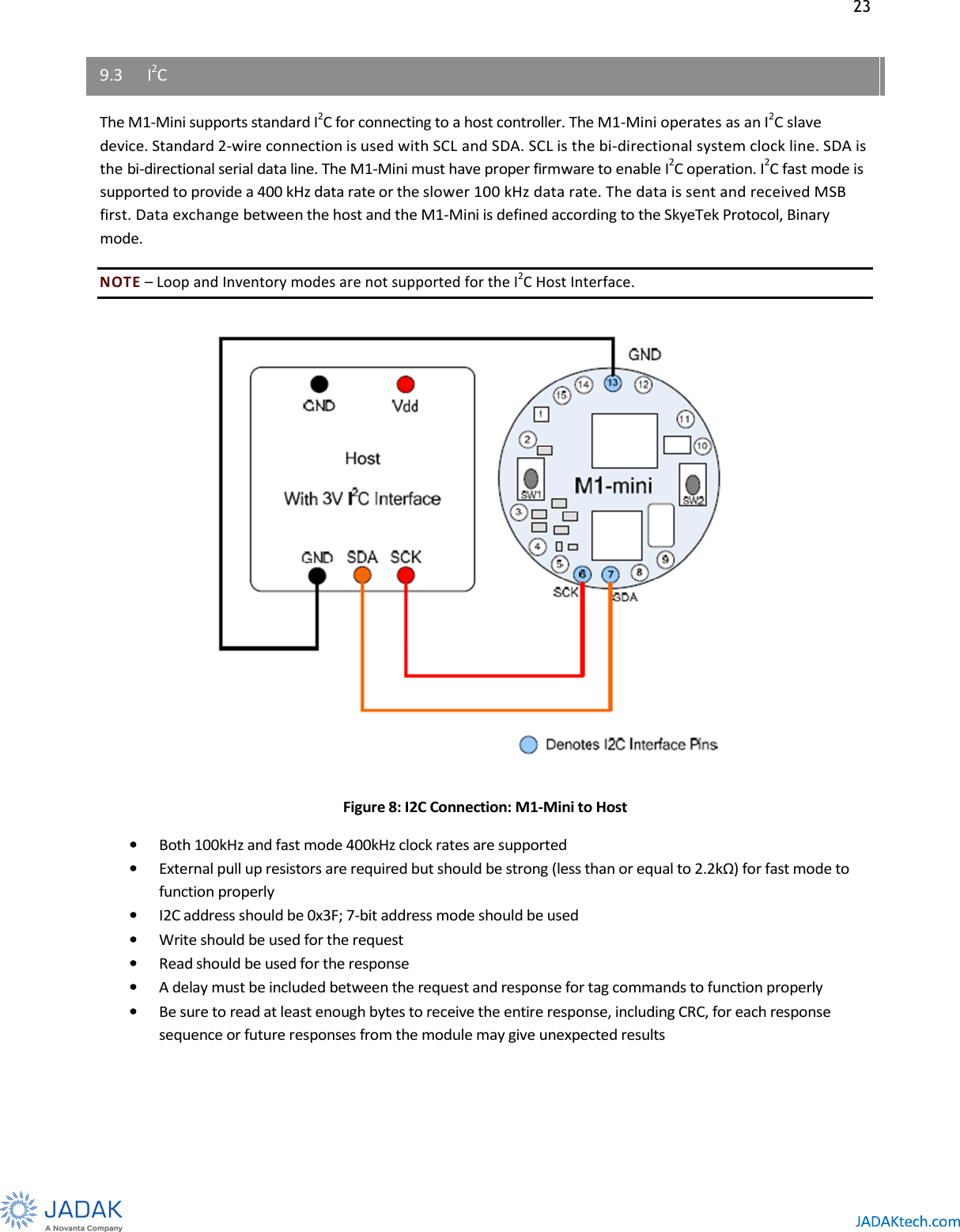
![13 4.1 Features • Tiny Footprint – 25.4 millimeter (mm) (1 inch) diameter • Low Profile Shielded Version (3.75 mm [0.147 in.]) • Ultra-low Profile (2.8mm [0.11in.] version available without shield and modular certifications • High Frequency (HF) RFID Tag support including ISO15693 and ISO 18000-3 • Supports SkyeTek Protocol version 2.0 • Standard Host Interface options include TTL, SPI, and I2C • On-board antenna provides up to 60mm (~2-inch) range with credit-card size tags • External antenna option with 50 Ohms output • Low voltage 3 volt (V) operation for Li-Ion battery-powered and handheld devices • Low-current consumption • Enhanced Noise Filtering for better RF performance • 180 mW maximum output power](https://usermanual.wiki/JADAK-a-business-unit-of-Novanta/SM-MN-SH/User-Guide-3932776-Page-13.png)