JADAK a business unit of Novanta SM-MN-SH M1-Mini User Manual M1 Mini User Guide 07132018
JADAK, a business unit of Novanta Corporation M1-Mini M1 Mini User Guide 07132018
M1-Mini User Guide Rev.pdf
M1-Mini User Guide
M1-MINI USER GUIDE
REV. 062918

M1-Mini User Guide
COPYRIGHT INFORMATION:
Copyright 2018 Novanta Corporation. All rights reserved.
Version 04/25/2018
This product or document is protected by copyright and distributed under licenses restricting its use, copying,
distribution, and decompilation. No part of this product or document may be reproduced in any form by any
means without prior written authorization of Novanta Corporation and its licensors, if any.
CryptoRF is a registered trademark of Atmel Corporation.
MIFARE and NXP is a registered trademark of Royal Philips Electronics.
Tag-it is a trademark of Texas Instruments, Incorporated.
Microsoft and Windows are registered trademarks of Microsoft Corporation.
TECHNICAL SUPPORT AND CONTACT
INFORMATION:
TELEPHONE: 315.701.0678
www.jadaktech.com
Email: RFID-support@jadaktech.com
3
TABLE OF CONTENTS
1
About this Document ................................................................................................................................................... 8
1.1
Intended Audience ............................................................................................................................................. 8
1.2
Topics Covered .................................................................................................................................................... 8
1.3
Topics Not Covered ............................................................................................................................................ 8
1.4
Additional Documentation ................................................................................................................................. 9
1.5
Revision History .................................................................................................................................................. 9
2
Definition of Terms ..................................................................................................................................................... 10
3
Ordering Information ................................................................................................................................................. 11
3.1
Part Numbers .................................................................................................................................................... 11
4
SkyeModule M1-Mini Overview ................................................................................................................................ 12
4.1
Features ............................................................................................................................................................. 13
5
Mechanical Specifications .......................................................................................................................................... 14
5.1
Dimensioned Drawings .................................................................................................................................... 14
6
Pinning Information .................................................................................................................................................... 15
6.1
Pin Locations ..................................................................................................................................................... 15
7
Environmental Specifications ..................................................................................................................................... 16
7.1
Electrostatic Precautions .................................................................................................................................. 16
7.2
Temperature Ratings ........................................................................................................................................ 16
8
Electrical Specifications .............................................................................................................................................. 17
8.1
Absolute Maximum Ratings ............................................................................................................................. 18
8.2
Power Supply Options ...................................................................................................................................... 19
9
Host Interface Specifications ...................................................................................................................................... 20
9.1
TTL Serial ........................................................................................................................................................... 20
9.2
SPI ...................................................................................................................................................................... 21

4
9.3
I
2
C ....................................................................................................................................................................... 23
10
Radio Specifications and Regional Compliance ................................................................................................... 24
10.1
Agency Approvals ............................................................................................................................................. 24
10.2
Modular Certifications ...................................................................................................................................... 24
10.3
Frequency Band ................................................................................................................................................ 24
10.4
Tag Protocols..................................................................................................................................................... 24
11
Antenna Options ................................................................................................................................................... 25
11.1
Read Range ....................................................................................................................................................... 25
11.2
Antenna Configurations ................................................................................................................................... 25
12
Communication Specifications ............................................................................................................................. 27
12.1
SkyeTek Protocol v2.......................................................................................................................................... 27
12.2
Request Formats ............................................................................................................................................... 27
12.3
Response Formats ............................................................................................................................................ 28
13
Customizing System Parameters .......................................................................................................................... 29
13.1
Changing System Parameters .......................................................................................................................... 30
13.2
System Parameter Descriptions....................................................................................................................... 31
13.2.1
Serial Number .......................................................................................................................................... 31
13.2.2
Firmware Version .................................................................................................................................... 31
13.2.3
Reader ID.................................................................................................................................................. 31
13.2.4
Baud Rate ................................................................................................................................................. 31
13.2.5
Sleep Mode .............................................................................................................................................. 31
13.2.6
Startup Command ................................................................................................................................... 32
14
Operating Modes .................................................................................................................................................. 33
14.1
Sleep Mode ....................................................................................................................................................... 33
14.1.1
Write System Parameter – Sleep Mode Example (ASCII)...................................................................... 33
14.1.2
Write System Parameter – Sleep Mode Example (Binary) ................................................................... 33
14.1.3
Write Memory – Sleep Mode Example (Binary) .................................................................................... 34

5
14.2
Loop Mode ........................................................................................................................................................ 35
14.2.1
Select Tag – Loop Mode Example (ASCII) ............................................................................................... 35
14.2.2
Select Tag – Loop Mode Example (Binary) ............................................................................................. 36
14.3
Startup Command ............................................................................................................................................ 37
14.3.1
Write System Parameter – Startup Command Example (ASCII) ........................................................... 37
14.3.2
Write System Parameter – Startup Command Example (Binary) ......................................................... 38
14.3.3
Write System Parameter – Disable Startup Command Functionality (ASCII) ...................................... 38

6
LIST OF FIGURES
Figure 1: Part Number Format .......................................................................................................................................... 11
Figure 2: M1-Mini Shielded ................................................................................................................................................ 12
Figure 3: M1-Mini Shielded Dimensions ............................................................................................................................ 14
Figure 4: Skyemodule M1-Mini Powered at VIN ≤ 5V ...................................................................................................... 19
Figure 5: TTL Connection: SkyeModule M1-Mini to Host ................................................................................................. 20
Figure 6: SPI Connection: SkyeModule M1-Mini to Host ................................................................................................. 21
Figure 7: Details of the SPI Communication Link ............................................................................................................... 22
Figure 8: I2C Connection: SkyeModule M1-Mini to Host ................................................................................................. 23
Figure 9: M1-Mini internal antenna schematic ................................................................................................................. 26
Figure 10: Component Positions on M1-Mini Shielded .................................................................................................... 27

7
LIST OF TABLES
Table 1-1: Revision History ................................................................................................................................................... 9
Table 6-1: Pin Locations ..................................................................................................................................................... 15
Table 7-1: Temperature Ratings ......................................................................................................................................... 16
Table 8-1: Electrical Specifications .................................................................................................................................... 17
Table 8-2: Maximum Voltage Ratings ............................................................................................................................... 18
Table 11-1: SkyeModule M1-Mini Internal Antenna Configuration Details ................................................................... 26
Table 12-1: Request Format (bytes), ASCII Mode ............................................................................................................. 28
Table 12-2: Request Format (bytes), Binary Mode ........................................................................................................... 28
Table 12-3: Response Format (bytes), ASCII Mode ........................................................................................................... 29
Table 12-4: Response Format (bytes), Binary Mode ......................................................................................................... 29
Table 13-1: SkyeModule M1-Mini System Parameters .................................................................................................... 30
Table 13-2: Baud Rate Parameter Settings ........................................................................................................................ 32

8
1
About this Document
1.1
Intended Audience
The topics described in this document are intended for technical personnel interested in the M1-Mini device.
1.2
Topics Covered
The following topics are discussed in this document:
•
Product overview
•
Transponder compatibility
•
Mechanical characteristics
•
Electrical characteristics
•
Tag timing table
•
Pin descriptions
•
Power supply
•
Host interface connections
•
Antenna connections
•
Host software
•
System parameters
1.3
Topics Not Covered
The following topics are covered in other documents offered through the "Technical Resources" section:
•
Protocol specifications
•
Troubleshooting
•
SkyeWare Protocol HF tag commands (AN002)

9
1.4
Additional Documentation
The following technical references provide additional information on the topics described in this document:
•
M1 Mini Tag Support Matrix
•
SkyeTek Protocol V2 Guide
•
Using Tag Commands with STPv2
1.5
Revision History
Revision Author Change
100112 Brad Alcorn Updated the formatting of the document and revised errors
110212 Brad Alcorn Minor updates to reflect microcontroller change to product
022714 Brad Alcorn Updates to the part number and fixed a broken link
082515 Steve Schneiter Minor updates to address and tag support
06092017 Eric S. Harden Add EU Declaration of Conformity, updated JADAK info
10112017 Eric S. Harden Added modular certification and new drawings for shielded version
10252017 C. Hatem Updated to new format/template
11142017 C. Hatem New Mechanical Drawing & deletion of Skyetek reference
04242018 C. Hatem, E. Harden New Mechanical Drawing
06292018 Victoria Mickelson Added FCC statement
Table 1-1: Revision History

10
2
Definition of Terms
3DES Triple Data Encryption Standard
AES Advanced Encryption Standard
API Application Programming Interface
DES Data Encryption Standard
HID Human Interface Device
HMAC Hash-based message authentication code
I
2
C Inter-integrated Circuit
LSB Least Significant Bit
MD5 Message-Digest Algorithm
MSB Most Significant Bit
NC No Connect
PRNG Pseudo-Random Number Generator
RoHS Reduction of Hazardous Substances
SHA Secure Hash Algorithm
SPI Serial Peripheral Interface
SSEL Slave Select
STP V3 SkyeTek Protocol Version 3
TTL Transistor-transistor Logic

11
3
Ordering Information
3.1
Part Numbers
The M1-Mini part number is constructed according to the part number specification below:
PF-PT-BT-OPTS
Product Family
Product Type
Build Type
Options
Figure 1: Part Number Format
Code Options Description
Product Family SM = SkyeModule Highest level product family code.
Product Type MN = M1-Mini Specifies the specific part type.
Build Type SH = Shielded Specifies hardware form factor.
Options Blank = Standard (TTL Serial)
I2C = I2C interface
SPI = SPI Interface
This field is left for special customer part numbers or standard variations such I2C
for I2C as the host interface. Consult the sales team for custom orders.
12
4
M1-Mini Overview
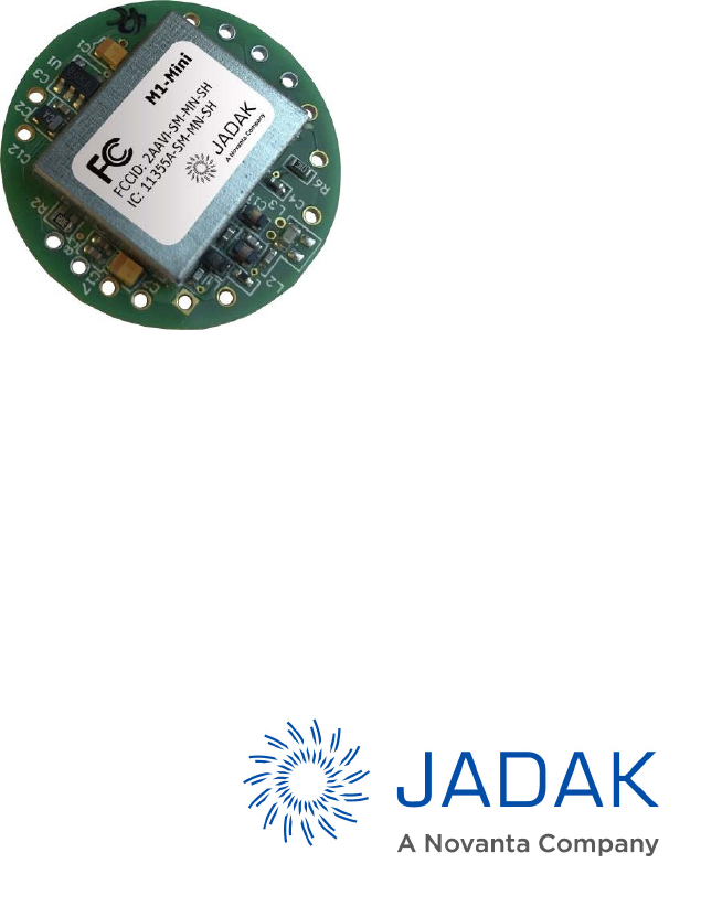
M1-Mini is the smallest multi-protocol radio frequency identification (RFID) read/write radio module in the
market, complete with internal antenna. The M1-Mini is a multi-protocol RFID read/write module for use with most
industry standard 13.56 megahertz (MHz) RFID tags and smart labels.
The extremely low-profile and low-power consumption of the M1-Mini makes it the ideal candidate for spatially
constrained, power-sensitive applications. An internal LDO regulator provides a low-noise 3V system voltage.
The M1-Mini offers multiple antenna options including an onboard antenna, the ability to connect a custom
external antenna, and the ability to utilize both the internal and external antennas together (though utilizing dual
antenna configuration requires advanced RF knowledge).
Figure 2: M1-Mini Shielded

13
4.1
Features
•
Tiny Footprint – 25.4 millimeter (mm) (1 inch) diameter
•
Low Profile Shielded Version (3.75 mm [0.147 in.])
•
Ultra-low Profile (2.8mm [0.11in.] version available without shield and modular certifications
•
High Frequency (HF) RFID Tag support including ISO15693 and ISO 18000-3
•
Supports SkyeTek Protocol version 2.0
•
Standard Host Interface options include TTL, SPI, and I
2
C
•
On-board antenna provides up to 60mm (~2-inch) range with credit-card size tags
•
External antenna option with 50 Ohms output
•
Low voltage 3 volt (V) operation for Li-Ion battery-powered and handheld devices
•
Low-current consumption
•
Enhanced Noise Filtering for better RF performance
•
180 mW maximum output power
14
5
Mechanical Specifications
5.1
Dimensioned Drawings
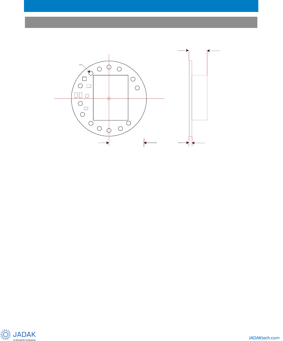
Figure 3: M1-Mini Shielded Dimensions
12.7 mm
0.5” radius
1.04mm (0.041”)
diameter
0.79 mm
(0.031”)
3.75 mm
(0.147”)

15
6
Pinning Information
6.1
Pin Locations
Table 6-1: Pin Locations
Pin Name X (Inches) Y (Inches)
1
GND
-0.290
0.315
2 ANT -0.370
0.230
3 RB7 -0.420
-0.120
4 RST/ -0.335
-0.275
5 RSSI Leave Open/Unconnected
Leave Open/Unconnected
6 TX TTL -0.120
-0.420
7 RX TTL 0.000
-0.430
8 SDO 0.120
-0.420
9 RB6 0.225
-0.375
10 SW1 0.420
0.120
11 SW2 0.370
0.230
12 Vin 0.100
0.420
13 GND 0.000
0.430
14 Vout -0.100
0.420
15 INT -0.190
0.392

16
7
Environmental Specifications
7.1
Electrostatic Precautions
CAUTION – Failure to take proper electrostatic precautions may result in damage to or failure of your
M1-Mini.
The M1-Mini contains static-sensitive parts. Observe the following precautions to prevent damage to these parts.
•
Wear a static grounding strap when handling electronic control components
•
Keep all plastic, vinyl, and Styrofoam (except antistatic versions) away from printed circuit boards.
•
Do not touch the components or conductors on a printed circuit board with your hands or with conductive
devices.
7.2
Temperature Ratings
Stresses beyond these ratings may cause permanent damage. Exposure to absolute maximum conditions for
extended periods may degrade device reliability. These maximum stress ratings do not imply maximum operating
conditions.
Table 7-1: Temperature Ratings
Specification Rating
Temperature range Temperature is 25 degrees Celsius unless otherwise noted
Operating -10 to +70 degrees C
Storage -20 to +85 degrees C

17
8
Electrical Specifications
This chapter discusses the electrical specifications of the M1-Mini. Unless otherwise noted, the following
assumptions apply to these specifications:
•
Temperature is 25 degrees Celsius.
•
Frequency is 13.56 MHz.
Table 8-1: Electrical Specifications
Specification Min Typ Max Units/Notes
RF Characteristics
Frequency (Direct output) 13.56 MHz
Transmission Parameters
Output Power 13.0 16.0 18.0 dBm
Optimum PA Load Impedance 50 Ohms
Logic Inputs
High state input voltage 2.4 V
Low state input voltage 0.45 V
Input Current (IINH/IINL) ± 20 mA
Logic Outputs
Output High Voltage (VOH) 2.3 3 V
Output Low Voltage (VOL) 0 0.6 V
Output Current (IINH/IINL) ± 20 mA
Power Supply
VIN Input Voltage Range 3.2 10 V
Power Supply Current consumption at 5V
Active (scanning) 60 mA
Idle 15 mA
Sleep 60 uA

18
8.1
Absolute Maximum Ratings
Stresses beyond these ratings may cause permanent damage. Exposure to absolute maximum conditions for
extended periods may degrade device reliability. These maximum stress ratings do not imply maximum operating
conditions.
Table 8-2: Maximum Voltage Ratings
Specification Rating
Maximum power supply voltage 10 V
Digital I/O voltage to GND -0.3 to 3.3V
19
8.2
Power Supply Options
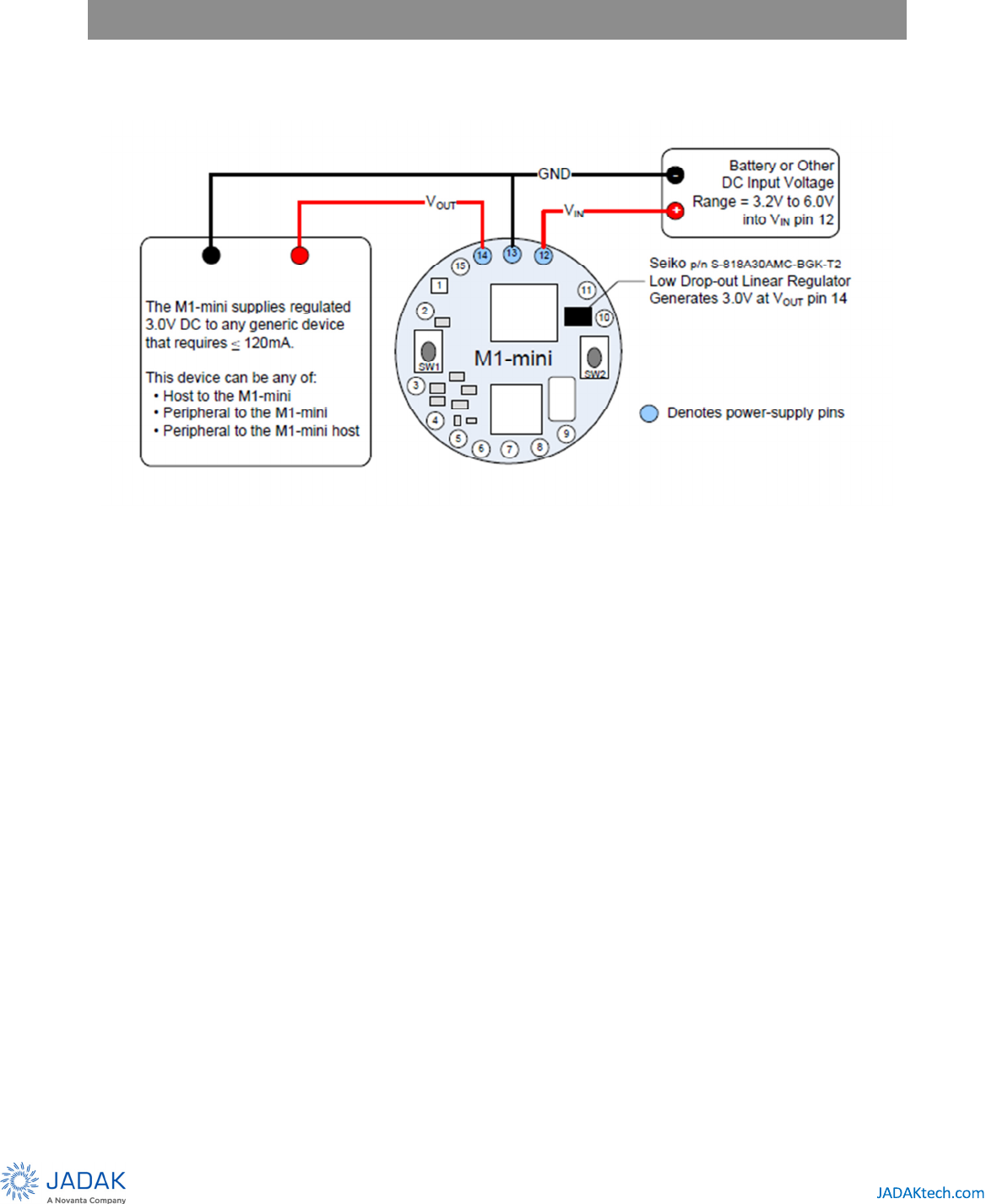
The power supply options for the M1-Mini are described in this section. The figure below shows an example the
standard power configuration.
Figure 4: M1-Mini Powered at VIN ≤ 5V
The M1-mini uses an on-board linear voltage regulator (LDO) that generates VOUT = 3.0V at pin 14, from supply-
voltage input to pin 12 within 3.2V ≤ VIN ≤ 6.0V.
20
9
Host Interface Specifications
The M1-Mini is supplied with TTL serial as the standard host interface. SPI and I
2
C host interface types are available
with separate firmware.
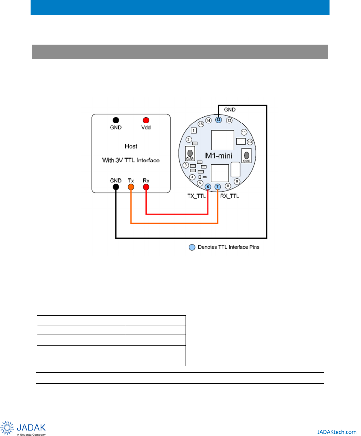
9.1
TTL Serial
TTL signal levels of 0 to 3V are used to interface the M1-Mini to a host device. A three-wire serial connection is
provided. The M1-Mini does not support RTS and CTS handshaking signals therefore Hardware Flow Control is not
available.
Figure 5: TTL Connection: M1-Mini to Host
•
In addition to the signal connections, the host must supply input voltage.
•
The serial baud rate of the M1-Mini is software selectable. The following table shows the selectable Baud
rates.
4800 bits/sec N,8,1
+/- 0.3% error
9600 bits/sec N,8,1
+/- 0.3% error
19200 bits/sec N,8,1
+/- 0.3% error
38400 bits/sec N,8,1
+/- 0.3% error
57600 bits/sec N,8,1
+/- 1.9% error
NOTE – N,8,1 means No Parity Bit, 8 Data Bits, 1 Stop Bit.
21
9.2
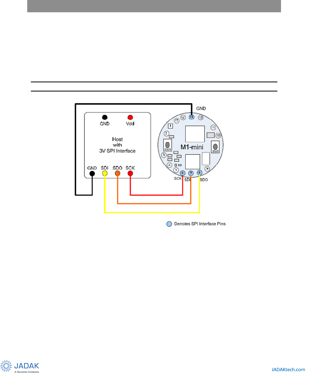
SPI
The M1-Mini allows the use of a standard Serial Peripheral Interface (SPI) for connecting to a host controller. The
M1-Mini must have the proper firmware to enable SPI operation. The M1-Mini operates as an SPI slave device; the
clock is always controlled by the host system. The SPI interface uses three wires: SCK, SDI, and SDO. SDO is the serial
data out (from the M1-Mini to the host system). SDI is the serial data in (to the M1-Mini from the host system). SCK
is the serial clock (controlled by the host system). The M1-Mini is set so that data is latched into and sent on the
positive edge of the SCK signal. Data is sent from the M1-Mini on the SDO signal at the same time that it is received by
the M1-Mini on the SDI signal. The data is sent and received MSB first. Data exchange between the host and the
M1-Mini is defined according to the SkyeTek Protocol, Binary mode.
NOTE – Loop and Inventory modes are not supported for the SPI host interface.
Figure 6: SPI Connection: M1-Mini to Host
•
In addition to the signal connections, the host must supply input voltage.
•
Care should be taken to minimize signal length between the host and the module.
22
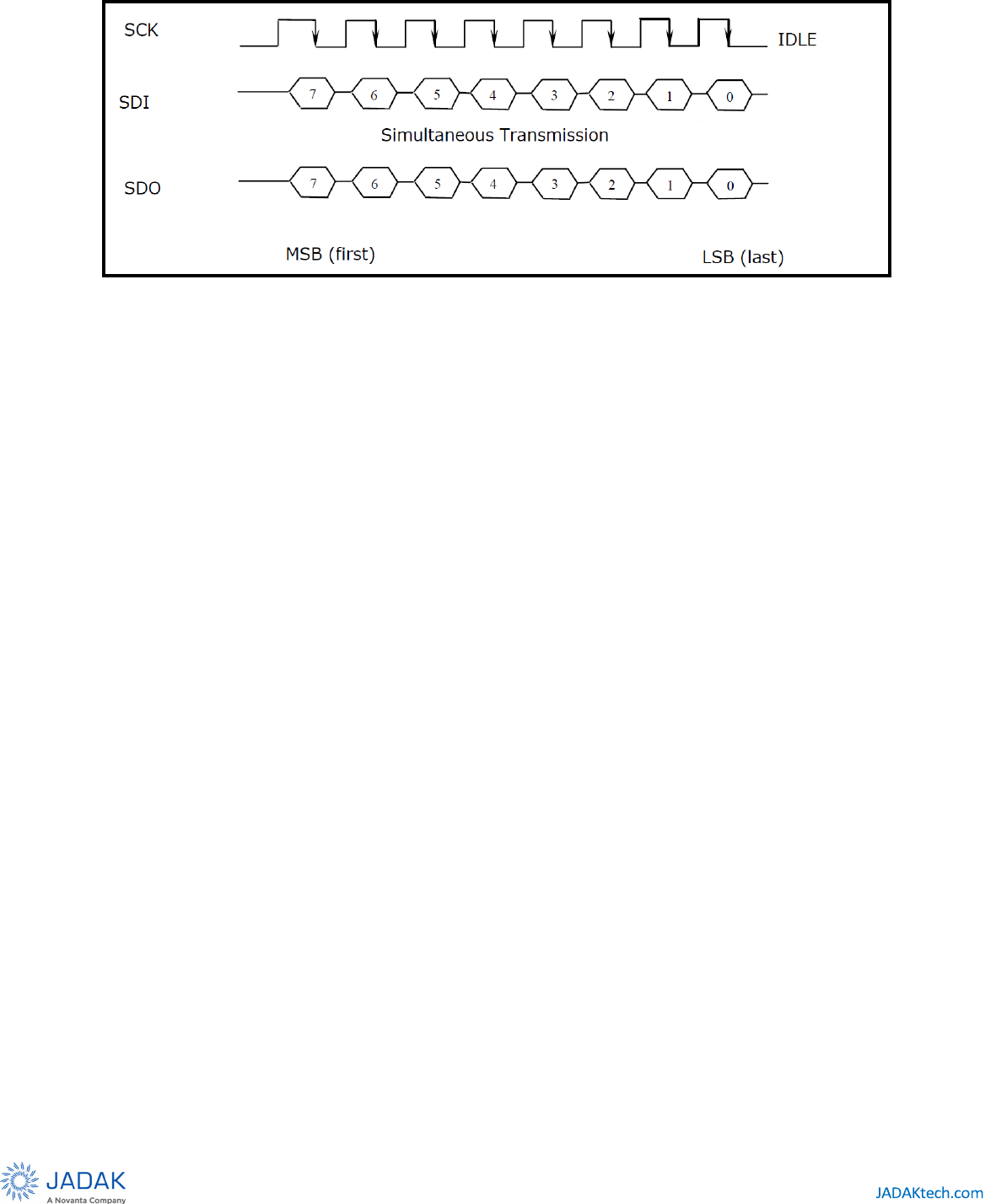
Figure 7: Details of the SPI Communication Link
•
Idle clock should be held low
•
Data is transitioned on the rising edge of the clock
•
Data is latched on the falling edge of the clock
•
Data is sent and received MSB first
•
The maximum clock rate is 3 MHz. Care should be taken to minimize the distance between M1-Mini and
host.
•
Host should wait at least 100us between each byte
•
Host should wait for the M1-Mini to finish executing the command before clocking the response
•
Commands should be sent to the M1-Mini at least 10ms apart
23
9.3
I
2
C
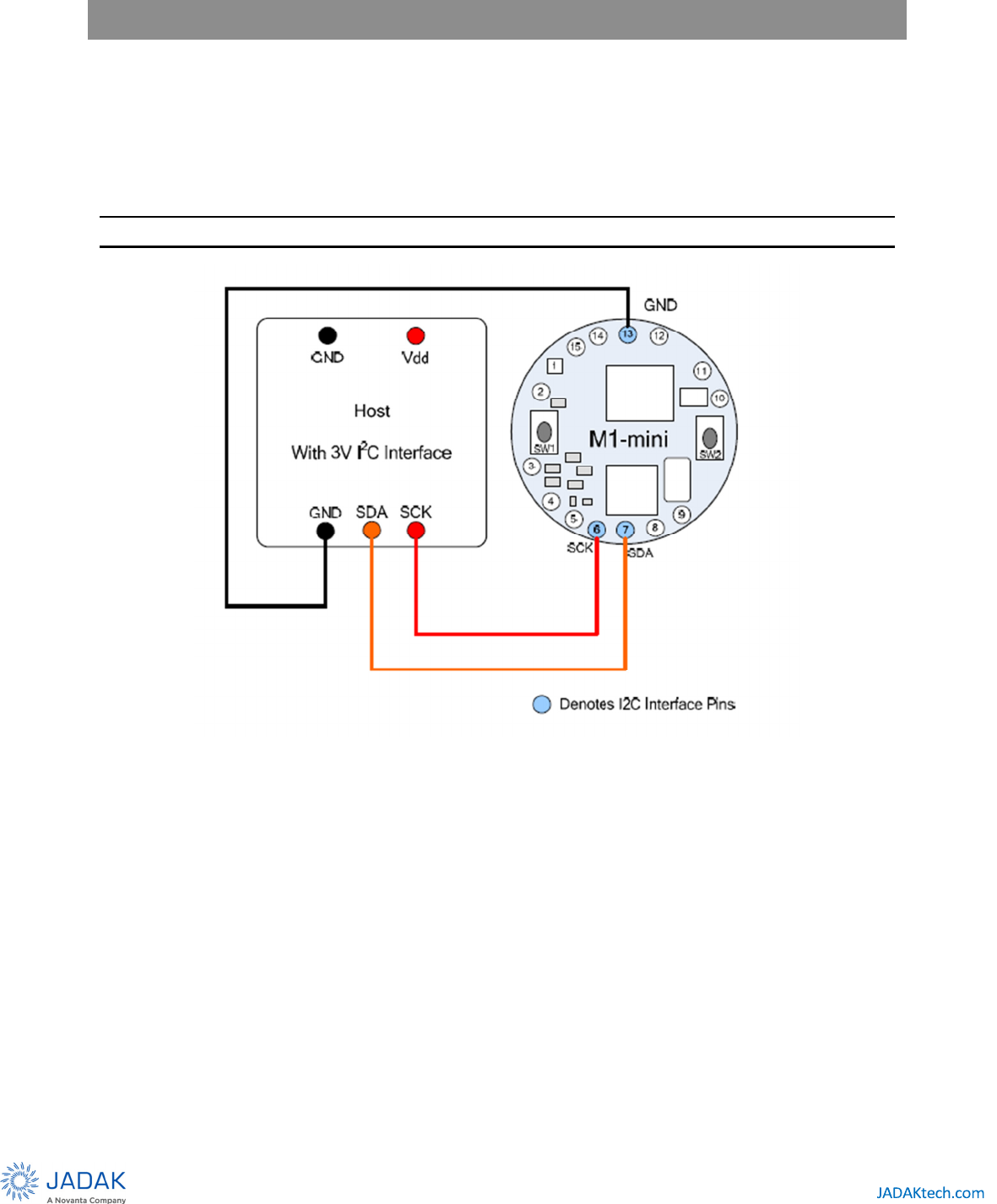
The M1-Mini supports standard I
2
C for connecting to a host controller. The M1-Mini operates as an I
2
C slave
device. Standard 2-wire connection is used with SCL and SDA. SCL is the bi-directional system clock line. SDA is
the bi-directional serial data line. The M1-Mini must have proper firmware to enable I
2
C operation. I
2
C fast mode is
supported to provide a 400 kHz data rate or the slower 100 kHz data rate. The data is sent and received MSB
first. Data exchange between the host and the M1-Mini is defined according to the SkyeTek Protocol, Binary
mode.
NOTE – Loop and Inventory modes are not supported for the I
2
C Host Interface.
Figure 8: I2C Connection: M1-Mini to Host
•
Both 100kHz and fast mode 400kHz clock rates are supported
•
External pull up resistors are required but should be strong (less than or equal to 2.2kΩ) for fast mode to
function properly
•
I2C address should be 0x3F; 7-bit address mode should be used
•
Write should be used for the request
•
Read should be used for the response
•
A delay must be included between the request and response for tag commands to function properly
•
Be sure to read at least enough bytes to receive the entire response, including CRC, for each response
sequence or future responses from the module may give unexpected results

24
10
Radio Specifications and Regional Compliance
10.1
Agency Approvals
As part of a host system, the M1-Mini will not interfere with the overall system’s compliance with agency
requirements for emissions and susceptibility, including:
•
United States: FCC 15.225
•
Europe: EN300-330, EN301-489, EN 61000-4-3, RoHS
•
Australia/New Zealand: AS/NZS 4268:2003
•
Taiwan: DGT LP002
•
Hong Kong: HKTA 1035
•
Singapore: IDA TS SRD
10.2
Modular Certifications
The M1-Mini has received the following modular certifications:
•
United States: FCC 15.225
o
FCC ID: 2AAVI-SM-MN-SH
•
ISED Canada RSS-210
o
IC ID: 11355A-SMMNSH
STATEMENT TO HOST DEVICE MANUFACTURER REGARDING END PRODUCT LABELING
The final end product must be labeled in a visible area with the following:
•
“Contains FCC ID: 2AAVI-SM-MN-SH” and “Contains IC ID: 11355A-SMMNSH”
FCC ID: 2AAVI-SM-MN-SH
FCC STATEMENT: This device complies with part 15 of the FCC
Rules. Operation is subject to the following two conditions:
(1) This device may not cause harmful interference, and (2)
this device must accept any interference received, including
interference that may cause undesired operation.
This device contains license-exempt transmitter(s)/receiver(s) that comply with Innovation, Science and
Economic Development Canada’s license-exempt RSS(s). Operation is subject to the following two conditions:
1.
This device may not cause interference.
2.
This device must accept any interference, including interference that may cause undesired operation of
the device.

25
Le présent appareil est conforme aux CNR Innovation, Sciences et Développement économique Canada
applicables aux appareils radio exempts de licence. L’exploitation est autorisée aux deux conditions suivantes:
1.
l’appareil ne doit pas produire de brouillage, et
2.
l’utilisateur de l’appareil doit accepter tout brouillage radioélectrique subi, même si le brouillage est
susceptible d’en compromettre le fonctionnement.
10.3
Frequency Band
The M1-Mini operates in the 13.56MHz (+/- 7 KHz) ISM unlicensed band and is suitable for worldwide use. The
frequency is not adjustable.
10.4
Tag Protocols
The M1-Mini supports ISO15693 tags. For the most current listing of supported tags and features, see the
M1 Mini Tag Support List.
26
11
Antenna Options
11.1
Read Range
In general, read range depends on the RFID Transponder’s IC and antenna, and the RFID reader and reader antenna,
in addition to the environment in which the system is implemented.
The M1-Mini has a read/write distance that is typically greater than or equal to 50.8 mm (2 inch) for a Texas
Instruments Tag-It HF-I (ISO15693) RFID inlay with antenna dimensions 22.5 mm x 38 mm (TI p/n RI-I03-112A)
11.2
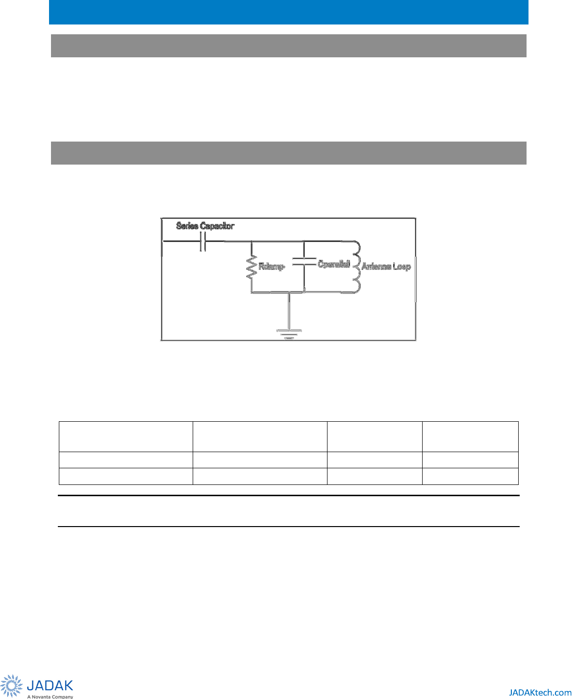
Antenna Configurations
By default the internal antenna of the M1-Mini is connected during production. In the event that the user wants to
connect an external antenna between the INT and ANT pins of the M1-Mini, refer to Table 14-1.
Figure 9: M1-Mini internal antenna schematic
Table 11-1: M1-Mini Internal Antenna Configuration Details
Internal Ant Active? Custom External Antenna? Remove Populate
N Y C
series
-
Y
N
C
series
NOTE – Place custom antenna between pin 2 (ANT) and pin 1 (GND). Refer to AN001 for more information on how
to make your own custom antenna.
The default M1-Mini configuration:
•
R
series
= shorted (connects the transmit and the receive path together)
•
C
series
= 220pF (This is essentially used to match the internal antenna to the output of the transceiver IC)
•
C
parallel
= 2000pf (This is the tuning cap value for the internal antenna)
•
R
damp
= unpopulated (R
damp
can be used to change the Q of the antenna circuit)
27
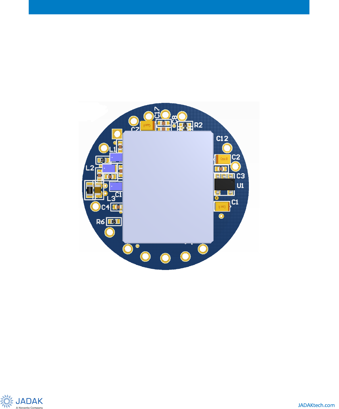
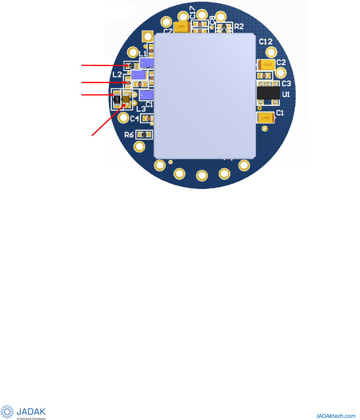
RDAMP
CPARALLEL
RSERIES
CSERIES
Figure 11-2: Component Positions on M1-Mini Shielded
Figure 10: Component Positions on M1-Mini Shielded

28
12
Communication Specifications
12.1
SkyeTek Protocol v2
The M1-Mini device communicates with a host controller using the SkyeTek Protocol v2 for all host interfaces. The
SkyeTek Protocol defines the data exchange between a host controller and a RFID radio module. It specifies how a
host controller can address, configure and command a radio module in order to read and write to RFID tags and
smart labels.
The following sections of this document explain a very basic overview of the protocol. Refer to the SkyeTek Protocol
v2 Guide document for detailed information.
12.2
Request Formats
Flags Cmd. RID Tag
Type TID AFI Starting
Block
# of
Blocks Data CRC
2 2 2 2 16 2 4 2 n 4
Table 12-1: Request Format (bytes), ASCII Mode
Msg.
Len. Flags Cmd. RID Tag
Type TID AFI
Starting
Block
# of
Blocks Data CRC
1 1 1 1 1 8 1 1 1 n 2
Table 12-2: Request Format (bytes), Binary Mode
Optional fields (depending on the command and flags)
Required Fields (must be present at all times)

29
12.3
Response Formats
Response
Code RID Tag
Type
Response
Data CRC
2 2 2 n 4
Table 12-3: Response Format (bytes), ASCII Mode
MSG
Length
Response
Code RID Tag
Type
Response
Data CRC
1 1 1 1 n 2
Table 12-4: Response Format (bytes), Binary Mode
Optional fields (depending on the command and flags)
Required Fields (must be present at all times)

30
13
Customizing System Parameters
System parameters let you configure reader settings to customize the reader for your environment. A
ll
parameters can be changed in both volatile and non-volatile memory. When changing a parameter in volatile
memory the change in the parameter is realized immediately, but is reset upon power-cycling the M1-Mini.
Alternatively, when changing a parameter in non-volatile memory the change in the parameter is not
realized immediately, but will only be realized after power-cycling the M1-Mini.
The following table summarizes the parameters for the M1-Mini.
Name
Parameter
Address
Request
Blocks
Length
(bytes)
Parameter Values Factory Default
Parameter Value Specifies READ WRITE
SERIAL
NUMBER 0x00
2 4 0x00000000-
0xFFFFFFFF
custom serial number
custom no
FIRMWARE
VERSION 0x01
1 2 0x0000-0xFFFF
depends on
release firmware version yes
no
READER ID
(RID) 0x02
1 1 0x00
-0xFF 0xFF (“no RID”) reader
network
ID yes yes
BAUD RATE 0x03
1 1
0xFF
0x00
0x01
0x02
0x03
0x04
-0xFE
0x00
4800
9600
19200
38400
57600
reserved
no
yes
SLEEP
MODE 0x04
1 1 0x00
0x01-0xFF not
applicable
sleep active
no
yes
Reserved 0x05
None
no no
Reserved 0x06
None
no no
USER PORT
DIRECTION 0x07
1 1
0x00
defines
pins
as inputs
or outputs
yes yes
USER PORT
VALUE 0x08
1 1
0x00
writes values of
output pins reads
values
of input pins
yes
yes
Reserved 0x09–0x11
None
no no
STARTUP
COMMAND 0x12
1 1 see
detailed
description
0x00
see
notes
no
yes
Reserved 0x13–0x80
None
no no
Table 13-1: M1-Mini System Parameters

31
13.1
Changing System Parameters
CAUTION – Changing system parameter values – especially the default values – can render your M1-
Mini non-operational in your environment. Research, record, and test all planned changes to make
sure they are compatible with your system.
You can read or write system parameters via the following commands:
•
Read System Parameter (0x22) – Reads the current value of the system parameter at the memory address
specified.
•
Write System Parameter (0x42) – Writes a new value to the system parameter at the memory address
specified.
•
Read Memory (0x21) – Reads the system parameter value at the address specified out of non-volatile
memory.
•
Write Memory (0x41) - Writes a new system parameter value to the non-volatile memory. This saves the
setting even after a power cycle or reset.
See System Parameter Descriptions in section 13.2 for detailed information about individual parameters.
Also, see the SkyeTek Protocol v2 Guide for a full description of the system parameter commands.
CAUTION – Resetting (or cycling power) on your M1-Mini causes all system parameters to revert to
their default values. Any changes made to system parameters in RAM are lost at reset unless you write
them to the non-volatile memory as the new default values. Any changes to the default values do not
take effect until the reader is reset.

32
13.2
System Parameter Descriptions
This section describes the M1-Mini system parameters in detail.
13.2.1
Serial Number
The Serial Number system parameter is a read only parameter set at manufacture time. It is not a unique number
for each module. It can be set to a specific value upon request. By default, it is set to 0x00000000.
13.2.2
Firmware Version
The Firmware Version system parameter is a read-only parameter that contains a two-byte firmware version
number. The firmware version number is read with a Read System command.
13.2.3
Reader ID
The Reader ID system parameter is a read/write system parameter that contains a one-byte Reader ID value.
The Reader ID can be changed in both volatile memory (Write System command) and nonvolatile memory (Write
Memory command). The Reader ID can be read out of either volatile (Read System command) or non-volatile memory
(Read Memory command). All non-volatile writes have to be followed by a power cycle before the settings take
effect. Reader ID values can take on any value from 0x00-0xFF. 0xFF is the default and the reader responds to
commands sent to it not containing the Reader ID. From this point forward examples some examples are in ASCII
mode and some are in binary mode.
13.2.4
Baud Rate
The Baud Rate system parameter controls the baud rate for serial data communication. The TTL serial interface. The
following table contains the possible values for the data field.
Baud Rate Data Field
4800 0xFF
9600 0x00
19200 0x01
38400 0x02
57600 0x03
Table 13-2: Baud Rate Parameter Settings
13.2.5
Sleep Mode
The reader can be set to a low power sleep mode through software using this system parameter. Sleep mode is
activated by setting this system parameter to 0x00. Sleep is explained in detail in the Operating Modes section of
the document, specifically section 14.1.

33
13.2.6
Startup Command
The Startup Command system parameter allows the user to set any command to run at module power up. This
command can be very useful in battery powered or otherwise power sensitive applications as it minimizes runtime.
The full functionality of this system parameter including examples is explained in detail in the Operating Modes
section of the document, specifically section 0.

34
14
Operating Modes
The M1-Mini has three operating modes: Sleep, Active, and Loop. Active is the normal mode of operation. The
following sections explain the Sleep and Loop modes as well as how to set a specific command to run on startup
using the Startup Command system parameter.
14.1
Sleep Mode
The low-power Sleep mode can be used to conserve battery or system power.
The reader can be put into Sleep mode by writing the Data 0x00 to the Sleep Mode system parameter using the
Write System command. After the reader gives a positive response, it enters Sleep mode. Any command wakes the
reader from Sleep mode. Even sending a single byte to the reader wakes it from Sleep mode. The reader gives the same
positive response upon waking from Sleep mode as it gives upon entering Sleep mode.
14.1.1
Write System Parameter – Sleep Mode Example (ASCII)
The following request puts the reader into Sleep mode if it is in active mode, and brings it out of Sleep mode if the
reader is already in Sleep mode.
Flag Command Starting
Block
Number of
Blocks Data CRC
Request <CR> 20 42 04 01 00 35E9 <CR>
Response CRC
Response <LF> 42 6116 <CR><LF>
14.1.2
Write System Parameter – Sleep Mode Example (Binary)
The following request puts the reader into Sleep mode if it is in active mode, and brings it out of Sleep mode if the
reader is already in sleep mode.
Length Flag Command Starting
Block
Number of
Blocks Data CRC
Request <STX> 0x07 0x20 0x42 0x04 0x01 0x00 0x35E9
Length Response CRC
Response <STX> 0x03 0x42 0x4B7E

35
14.1.3
Write Memory – Sleep Mode Example (Binary)
The following request puts the reader into Sleep mode upon power up. This process is done provided that no
startup command is stored using the Startup Command system parameter.
Flag Command Starting
Block
Number of
Blocks Data
Request <CR> 00 41 04 01 00 <CR>
Response
Response <LF> 41 <CR><LF>

36
14.2
Loop Mode
Loop mode allows the user to send a single select tag command to the reader and receive responses from the
reader each time a tag is present in the field with no further requests necessary. The loop flag is used in conjunction
with the Select Tag command to set the reader into Loop mode.
NOTE – Loop Mode is not supported for the SPI or I
2
C host interface.
14.2.1
Select Tag – Loop Mode Example (ASCII)
The following request initiates Loop Mode with Auto-detect selected as the tag type:
Flag Command Tag Type
Request <CR> 01 14 00 <CR>
Response
Response <LF> 1C <CR><LF>
The response 1C is immediately sent to indicate that the reader has successfully entered loop mode.
The following responses will be received when an ISO-15693 tag is introduced into the reader’s field. The responses
below show the tag being read three times:
Response Tag Type Data (TID)
Response <LF> 14 01 E0 07 00 00 01 64 5E 37 <CR><LF>
Response <LF> 14 01 E0 07 00 00 01 64 5E 37 <CR><LF>
Response <LF> 14 01 E0 07 00 00 01 64 5E 37 <CR><LF>

37
14.2.2
Select Tag – Loop Mode Example (Binary)
The following request initiates Loop Mode with Auto-detect selected as the tag type:
Length Flag Command Tag Type CRC
Request <STX> 0x05 0x21 0x14 0x00 0xC541
Length Response CRC
Response <STX> 0x03 0x1C 0xF085
The response 1C is immediately sent to indicate that the reader has successfully entered loop mode.
The following responses will be received when an ISO-15693 tag is introduced into the reader’s field. The responses
below show the tag being read three times:
Length Response Tag Type Data (TID) CRC
Response <STX> 0x0C 0x14 0x01 E0 04 01 00 08 AE D8 BD 0xBBF3
Response <STX> 0x0C 0x14 0x01 E0 04 01 00 08 AE D8 BD 0xBBF3
Response <STX> 0x0C 0x14 0x01 E0 04 01 00 08 AE D8 BD 0xBBF3

38
14.3
Startup Command
The M1-Mini has a provision to store a single command that is executed upon power up. This command is stored by
writing to the Startup Command system parameter using the Write System command. The M1-Mini executes the
command upon power up and sends the response in either Binary or ASCII mode depending on the mode in which
the command was stored.
The entire command must be stored—all the fields relevant to the command must be present. For example if the
CRC, TID and/or RID flags are set, then the respective fields must have the correct information. In the case of Binary
mode, the message length must also be stored as part of the command. The delimiting characters (<CR> in ASCII
mode and <STX> in Binary mode) should not be stored.
This system parameter can only be written for the Write System command, so there is no Read System and
Write/Read Memory support for this system parameter.
If no command needs to be executed upon power up, then a single-byte data value should be written to this system
parameter. This process turns off the Start Up command functionality. The single byte can be any value, for example
0x00 – 0xFF.
14.3.1
Write System Parameter – Startup Command Example (ASCII)
The following request stores the Select Tag (0x14) command with tag type ISO-15693 (0x01) to be executed upon
startup. Since the command is stored in ASCII mode, the response upon power up is sent in ASCII mode.
Flag Command Starting
Block
Number of
Blocks Data
Request <CR> 00 42 12 01 00 14 01 <CR>
Response
Response <LF> 42 <CR><LF>

39
14.3.2
Write System Parameter – Startup Command Example (Binary)
The following request stores the select tag command (0x14) with the tag type set to Auto-Detect (0x00). The flags
field in the command, which is stored, shows that the CRC and the Loop flags are set (0x21). This process causes
the reader to go into loop mode upon power up and sends responses in Binary mode along with the CRC. The
message length (0x05) is also stored along with the rest of the command because it is part of any command sent
in Binary mode.
Length Flag Command Starting
Block
Number of
Blocks Data CRC
Request <STX> 0x0C 0x20 0x42 0x12 0x01 0x05211400C541 0xD591
Length Response CRC
Response <STX> 0x03 0x42 0x4B7E
14.3.3
Write System Parameter – Disable Startup Command Functionality (ASCII)
The following request turns off the Start Up command functionality. It is sent in ASCII mode.
Flag Command Starting
Block
Number of
Blocks Data
Request <CR> 00 42 12 01 00 <CR>
Response
Response <LF> 42 <CR><LF>