JAVAD GNSS FH915 FH915 Radio Module User Manual JAVAD GNSS
JAVAD GNSS, Inc. FH915 Radio Module JAVAD GNSS
UserManual.wiki
>
JAVAD GNSS
>
FH915 User Manual
Users Manual
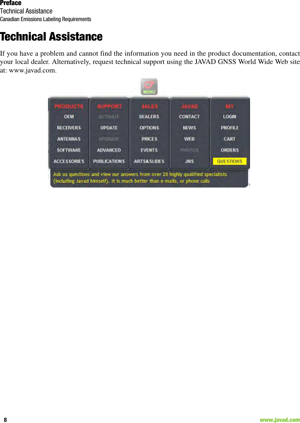
Navigation menu
Upload a User Manual
Namespaces
Wiki Guide
HTML
PDF
Info
Views
User Manual
Discussion / Help
Navigation


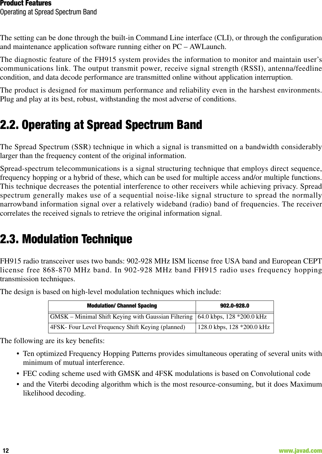
![Product FeaturesModulation TechniqueMedia Access Control (MAC)13www.javad.com In 868-870 MHz band the design is based on high-level modulation techniques which includeThe following are its key benefits:• FEC coding scheme used with GMSK and 4FSK modulations is based on Convolutional code andthe Viterbi decoding algorithm. • Powerful FEC scheme used with JAVAD GNSS proprietary frame format improves the toleranceto interference and ensures the highest link quality at distances range higher than 8 miles (13 km)and roaming speeds of up to 60 mph (96 km/h).2.3.1. Media Access Control (MAC)The following Media Access protocols are available for FH915 modem:1. Simplex protocols (Simplex Base, Simplex Remote, and Repeater) are developed primarily forGNSS applications.2. Half Duplex protocols (Half Duplex Base, Half Duplex Remote and Repeater) are the alternativeto Simplex protocols that provide bidirectional link with the dynamic bandwidth allocation.Note: Repeater decreases the user data rate. The user data rate in the link with the repeaters is equal to C /[(n+1]), where C is a link throughput determined by the modulation technique and n is a number ofrepeaters in the chain. Half duplex Base, Half duplex Remote and repeater are not supported in currentrelease.3. Sleep mode is an investment provided by MAC sub-layer that provides additional power saving.The wakeup from Sleep mode is user selectable either by an internal real-time clock, or by anexternal controller through the data interface control lines (RTS or DTR), or by SLEEP input line(CMOS/TTL compatible input lines).2.3.2. Operating ModesThe operating modes for FH915 can be set through the CLI, and/or through AWLaunch. The followingoperating modes are available for FH915:1. The sleep mode has automatic transmitter activation by an internal real-time clock, or by anexternal controller through the data interface control lines (RTS and DTR), or by the triggering ofthe external Sense Inputs.2. Adaptive RF Power control used by Remotes minimizes the transmit power levels andinterference to co-channel and adjacent channel users. It also reduces the Remote’s powerconsumption.Modulation/ Channel Spacing 12.5 kHz 20 kHz 25 kHzGMSK – Minimal Shift Keying with Gaussian Filtering 4.8 kbps 7.5 kbps 9.6 kbps4FSK- Four Level Frequency Shift Keying (planned) 9.6 kbps 15 kbps 19.2 kbps](https://usermanual.wiki/JAVAD-GNSS/FH915/User-Guide-1418512-Page-13.png)
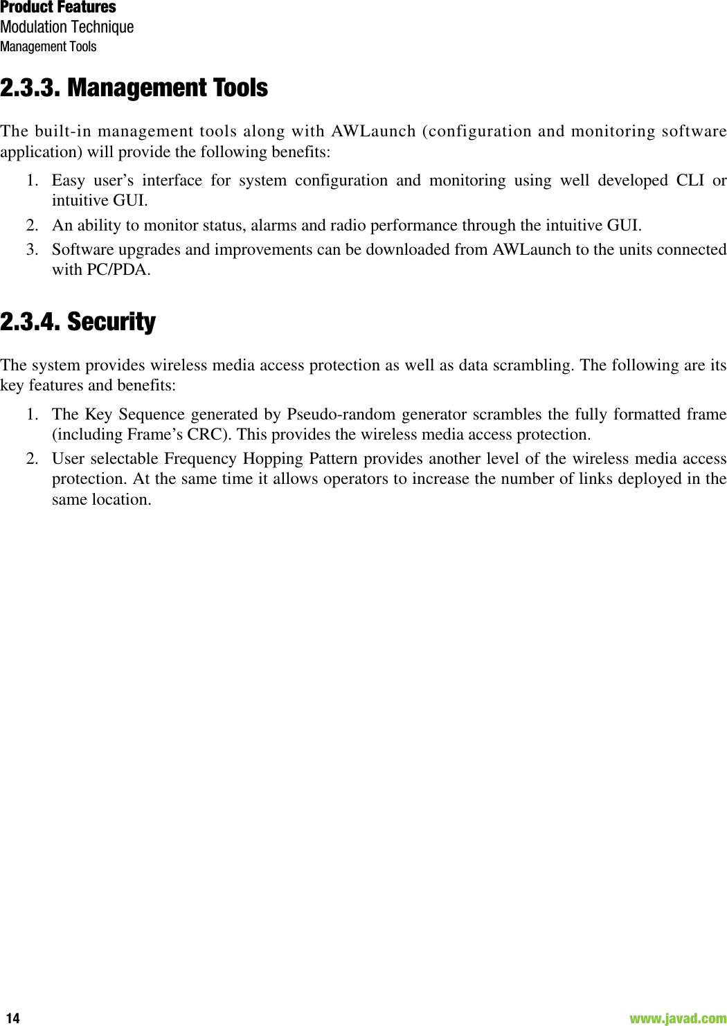
![Command Line InterfaceCommand Line Interface ConventionSoftware Switching to Maintenance Mode18 www.javad.com• The Carriage Return/Line Feed (CR/LF, 0x0D/0x0A) is a command delimiter. Commanddelimiters CR or LF or CR+LF are valid. • The Carriage Return/Line Feed (CR/LF, 0x0D/0x0A) is a reply delimiter followed by the “CLI>”prompt if Echo option is On.• The Carriage Return/Line Feed (CR/LF, 0x0D/0x0A) is a reply delimiter if Echo option is Off(default option).• The 2-digit number followed by “@” in the unit’s reply indicates the error code (refer to Table 4-1 for description), if Echo Off is selected, otherwise the error message is displayed.• A successfully performed command is replied by @00 code, if Echo Off is selected, otherwise theset value is replied.• A command with the certain [Parameter Name] and blank [Parameter List] displays the currentsettings for a given parameter.• To set the mode ordered by CLI commands as permanent User Setting (the setting automaticallyselected for the boot-up unit) the SAVE command must be asserted.• [/?] orders to show the help information for the given command.• Commands are not key sensitive; small, none capital characters can be used to enter CLIcommands.Table 4-1. Command Line Interface Error Codes4.1.1. Software Switching to Maintenance ModeSoftware Switching to Maintenance Mode can be utilized if Data/Maintenance Port (DP/MP) control lineis set to High Z (or 3.3v) level. To switch to Maintenance mode the special byte-sequences with specialmeanings are used:• Escape-Sequence: “+++” with 20 ms guard time before and after the command characters• Escape-Acknowledge: “@00<CR><LF>” 20 ms toggling on CTS control line needed toacknowledge switching from Data to Maintenance mode and vice versa. In Maintenance mode,the unit’s serial port must keep CTS line always active.Error Code Short Description0x01 Command Syntax Error. A command followed by “/?” displays a command usage.0x02 The parameter has a format error. A command with the certain [Parameter Name] followed by “/?” displays the format and range of the variable.0x03 The parameter is out of allowed range. A command with the certain [Parameter Name] followed by “/?” displays the format and range of the variable.0x04 The command is not valid for specific radio model. To display the list of available commands, the HELP command must be used (see “Software Switching to Maintenance Mode” ).0x05 Unspecified Error](https://usermanual.wiki/JAVAD-GNSS/FH915/User-Guide-1418512-Page-18.png)
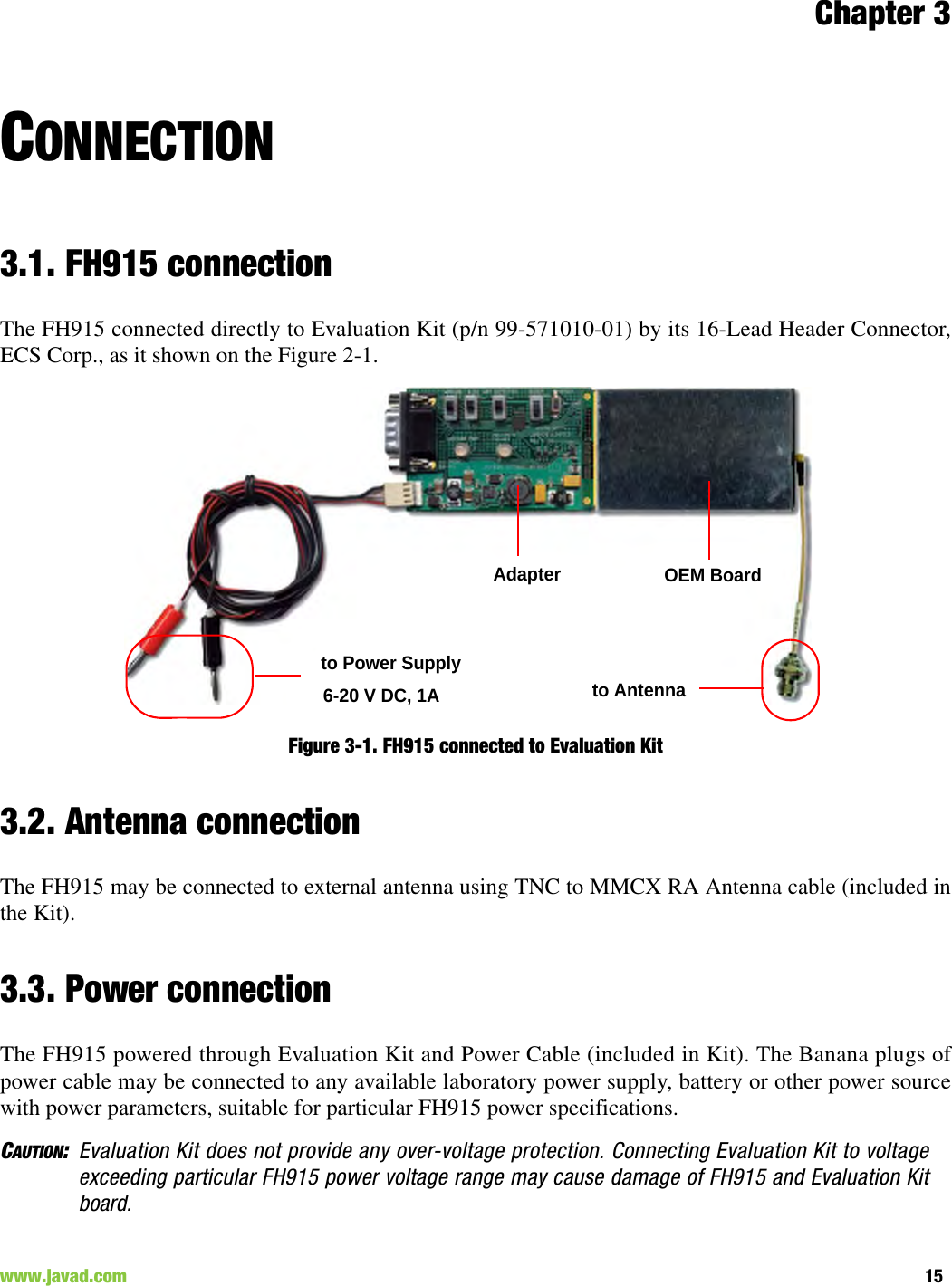
![Command Line InterfaceNetworking CommandsCONNECT20 www.javad.com• Unit answers with Escape-Acknowledge („@00<CR><LF>“) and immediately goes to datamode,so that the DTE can start sending data as soon as the Escape-Acknowledge has been received.• If no valid CLI commands received from DTE within 1 minute, the unit will automatically switchback to data-mode.Note: The data received over the air could be lost due to Rx buffer overflow if the unit stays in Maintenancemode longer then 15 second.4.2. Networking Commands4.2.1. CONNECTTo connect the radio unit through the local maintenance serial port or to establish the link with the remoteunit in the Point-to-Multipoint network, the CONNECT command must be used.CONNECT [Unit_Numb] [/?]Where the Unit_Numb is an assigned decimal number for the unit to be connected. To get the completeunit list, the CONNECT command must be used with no parameter. The list of units in the Point-to-Pointlink with the connection established with remote unit is shown in Figure 4-1:Figure 4-1. Connection ListTo disconnect from the remote unit and connect to the local unit, the parameter (Unit_Numb) must beequal to 0x00.4.2.2. LINKThe LINK command is responsible for configuring radio’s operation mode. It has six parameters listedbelow.LINK [Parameter Name] [Parameters List] [/?]LINK commands are as common so specific for two bands: 902-928 MHz band and 868-870 MHz band.Commands common for two bands:Unit Serial Number ConnectBS 0035786599221 003574459923 CParameter Name Parameter ListFEC 0 – Disable Forward Error Correction, a default setting (see note below)1 – Enable Forward Error Correction (see note below)FHOP (0-9) - Frequency Hoping Pattern numbers for USA;(10-19) - Frequency Hoping Pattern numbers for Australia;](https://usermanual.wiki/JAVAD-GNSS/FH915/User-Guide-1418512-Page-20.png)
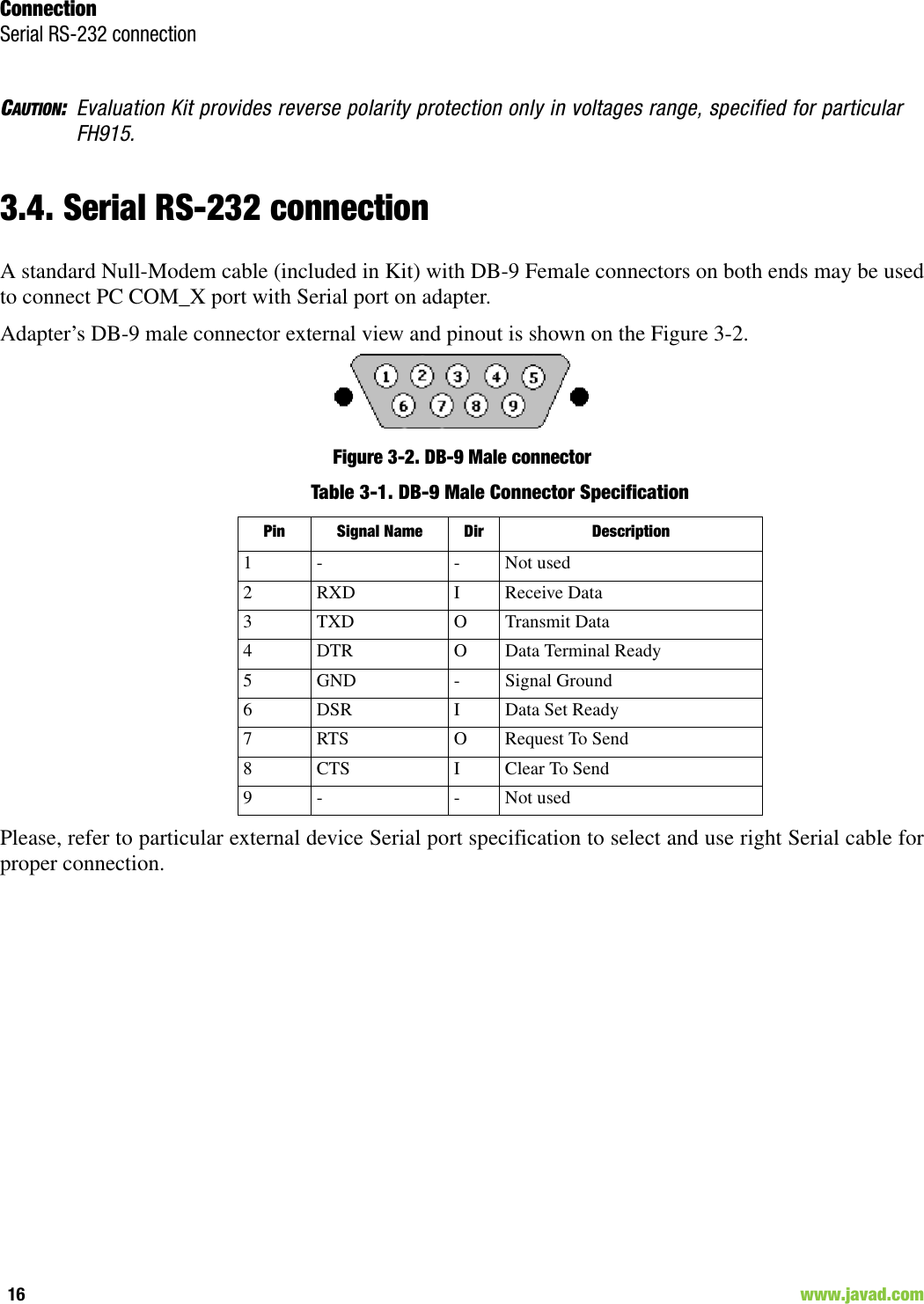
![Command Line InterfaceSerial Interfacing CommandsDPORT22 www.javad.comNote: The frequency defined by CHAN parameter is not valid if Frequency Hoping mode is selected. “HalfDuplex” Base and “Half Duplex” Remote protocols are not supported in current release.4.3. Serial Interfacing Commands4.3.1. DPORTThe DPORT is an object that responsible for data port interface configurations like Bit Rate, FlowControl, etc.DPORT [Parameter Name] [Parameters List] [/?]4.3.2. MPORTThe MPORT is an object that responsible for maintenance serial port interface configurations such as datarate and number of bits in a byte.MPORT [Parameter Name] [Parameters List] [/?]Parameter Name Parameter ListRATE 0 – Maintenance Port baud rate, a default setting1 – 1200 baud2 – 2400 baud3 – 4800 baud4 – 9600 baud5 – 14400 baud6 – 19200 baud7 – 38400 baud8 – 57600 baud9 – 115200 baud, a default settingBITS Set number of bits in one byte (8 or 7) 8 is a default settingPARITY 0 – None, a default setting1 – Odd2 – EvenFLOW 0 – None 1 – Not used2 - HW (RTS/CTS), a default settingParameter Name Parameter ListRATE 0 – Auto.1 – 1200 baud2 – 2400 baud3 – 4800 baud4 – 9600 baud5 – 14400 baud6 – 19200 baud7 – 38400 baud8 – 57600 baud9 – 115200 baud, a default setting](https://usermanual.wiki/JAVAD-GNSS/FH915/User-Guide-1418512-Page-22.png)
![Command Line InterfaceSpecial CommandsALARM23www.javad.com Note: JAVAD GNSS radio modem’s does not support data flow and parity on the maintenance serial port.MPORT operates using 8 bits in one byte fixed (not configurable).The radio modem with none-dedicated maintenance serial port must keep CTS line always active inMPORT mode (DP/MP is low).4.4. Special Commands4.4.1. ALARMThe ALARM command is intended to set up the alarm indication mode and alarm control lines’ behavior.ALARM [Parameter Name] [Parameters List] [/?]The Alarm LED must indicate the SYNC Loss and BER exceeding the defined threshold.Note: The BERTH 1 / 2 is optional for TTL2 = 3 condition, otherwise the BERT alarm is off4.4.2. BOOTThe BOOT command is intended to reboot the unit using selected user settings. Two options areavailable, to use the default user settings defined by dealer or to use the settings defined by end-user BOOT [Parameter Name] [Parameters List] [/?] The BOOT command with no parameters selects the user settings defined by the prior “parameterized”BOOT commands.4.4.3. HELPThe HELP command types the list of all available commands:HELP – Display this usageParameter Name Parameter ListTTL1 0 – TTL_OUT1 = logic “1”1 – TTL_OUT1 = TTL_IN, received from remote unit (default settings)TTL2 0 – TTL_OUT2 = logic “1”1 – TTL_OUT2 = TTL_IN2, received from remote unit (default settings)2 – TTL_OUT2 = SYNC Loss3 – TTL_OUT2 = BER > BERTH or SYNC LossBERTH 1– BER Threshold >10 –3 (default threshold level for BER)2 – BER Threshold BER >10 –2Parameter Name Parameter ListCFG 0 – selects the default user settings1 – selects user modified settings](https://usermanual.wiki/JAVAD-GNSS/FH915/User-Guide-1418512-Page-23.png)
![Command Line InterfaceSpecial CommandsSAVE24 www.javad.comBOOT – Reboot the unitLINK – RF Link Operation ModeDPORT – Data Port ConfigurationMPORT – Maintenance Port ConfigurationALARM – Alarm Indication and Alarm Control ConfigurationSLEEP – Sleep Mode ConfigurationCONNECT – Connect to Specified UnitSTATE – Display Status and StatisticsSAVE – Save Current Configuration into Configuration FileINFO – Display Product ID along with Hardware/Software VersionsDATAMODE – Exit Maintenance Mode[COMMAND] /? – Display Command Usage4.4.4. SAVEThe SAVE command is intended to store the unit’s currently used configuration into the UserConfiguration file. The configuration stored in the User Configuration file is activated by automaticallyafter unit’s reboot.4.4.5. SLEEPThe SLEEP command determines the sleep mode parameters. The sleeping FH915 can be activated byreal-time CLK, DTR/RTS lines, and command received through TTL inputs. The user can select one,two, or all three conditions.SLEEP [Parameter Name] [Parameters List] [/?] Parameter Name Parameter ListCLK 0 – Do not activate by internal real-time clock(1 – 255) – Activate by internal real-time clock after 100 to 25500 msec of sleepingHW 0 – Do not activate through DTR/RTS lines1 – Activate through DTR/RTS linesTTL 0 – Do not activate by external sense lines1 – Activate by external sense linesGTS 0 – Disable Sleep mode (default)(1 – 255) – Go to sleep mode if there is no activity in 10 to 2550 msec](https://usermanual.wiki/JAVAD-GNSS/FH915/User-Guide-1418512-Page-24.png)
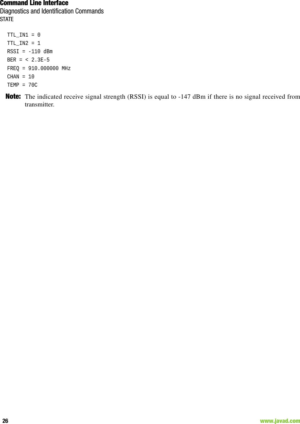
![Command Line InterfaceDiagnostics and Identification CommandsINFO25www.javad.com 4.5. Diagnostics and Identification Commands4.5.1. INFOThe INFO command is used to retrieve the Radio ID along with its Hardware version, the loaded real-time software version/revision and BootLoader’s version/revision.INFO [Parameter Name] [Parameters List] [/?]The INFO command without Parameter Name indicates all values:FH915 Spread Spectrum Radio Modem.Product ID =41S/N = 11327Hardware =2.0Firmware =2.1.9BootLoader =4.034.5.2. STATEThe STATE command is used to check the state of the wireless link, the unit in the link, and the alarmcontrol lines. To specify a radio unit (local or remote), the CONNECT command must be used in prior ofSTATE command using.STATE [Parameter Name] [Parameters List] [/?]The STATE command without Parameter Name indicates all values:Parameter Name Parameter ListID Product IDSN Six bytes Serial Number (SN)HW 1.0 – hardware revisionFW Ver. 1.0 Rev. A – displays software’s version in numeric “Major.Minor” format and revision in numeric format (range from 01 to 99) for engineering releases and alphabetic format (A to Z) for manufacturing releasesBL BootLoader Version Parameter Name Parameter ListTTL1 0/1 – State of TTL_IN1 lineTTL2 0/1 – State of TTL_IN2 lineRSSI -52 to -116 dBm – Indicates the Receive Signal Strength in dBmBER 1.0E-6 to 9.9E-3 – Indicates the BER levelFREQ 902.000000 to 928.000000 MHz – Displays the central frequency of the operating channelCHAN 1 to 9601 – Displays the selected or currently scanned frequency channelTEMP -30°C to 100°C – Displays the temperature inside of enclosure](https://usermanual.wiki/JAVAD-GNSS/FH915/User-Guide-1418512-Page-25.png)