JAVAD GNSS FH915 FH915 Radio Module User Manual JAVAD GNSS
JAVAD GNSS, Inc. FH915 Radio Module JAVAD GNSS
Users Manual

All contents in this manual are copyrighted by JAVAD GNSS.
All rights reserved.The information contained herein may not be used, accessed, copied,
stored, displayed, sold, modified, published, or distributed, or otherwise reproduced without express written
consent from JAVAD GNSS
FH915
Operator’s Manual
Version 2.1
Last Revised January 19, 2011
www.javad.com
3www.javad.com
TABLE OF CONTENTS
Preface . . . . . . . . . . . . . . . . . . . . . . . . . . . . . . . . . . . . . . . . . . . . . . . . . . . . . . . . . . . . . . 5
Terms and Conditions. . . . . . . . . . . . . . . . . . . . . . . . . . . . . . . . . . . . . . . . . . . . . . . . . . . . . . . .5
Regulatory Information . . . . . . . . . . . . . . . . . . . . . . . . . . . . . . . . . . . . . . . . . . . . . . . . . . . . . .6
FCC Class B Compliance . . . . . . . . . . . . . . . . . . . . . . . . . . . . . . . . . . . . . . . . . . . . . . . . .6
Canadian Emissions Labeling Requirements . . . . . . . . . . . . . . . . . . . . . . . . . . . . . . . . . .7
WEEE Directive . . . . . . . . . . . . . . . . . . . . . . . . . . . . . . . . . . . . . . . . . . . . . . . . . . . . . . . . . . . .7
Technical Assistance . . . . . . . . . . . . . . . . . . . . . . . . . . . . . . . . . . . . . . . . . . . . . . . . . . . . . . . .8
Chapter 1. General Description. . . . . . . . . . . . . . . . . . . . . . . . . . . . . . . . . . . . . . . . . . . . 9
1.1. Physical Interfaces. . . . . . . . . . . . . . . . . . . . . . . . . . . . . . . . . . . . . . . . . . . . . . . . . . . . . . .9
1.1.1. Serial Data Interface . . . . . . . . . . . . . . . . . . . . . . . . . . . . . . . . . . . . . . . . . . . . . . . .9
1.1.2. Power Interface . . . . . . . . . . . . . . . . . . . . . . . . . . . . . . . . . . . . . . . . . . . . . . . . . . . .9
1.1.3. Power Consumption . . . . . . . . . . . . . . . . . . . . . . . . . . . . . . . . . . . . . . . . . . . . . . . .9
1.1.4. Antennas . . . . . . . . . . . . . . . . . . . . . . . . . . . . . . . . . . . . . . . . . . . . . . . . . . . . . . . .10
Chapter 2. Product Features. . . . . . . . . . . . . . . . . . . . . . . . . . . . . . . . . . . . . . . . . . . . . 11
2.1. Introduction . . . . . . . . . . . . . . . . . . . . . . . . . . . . . . . . . . . . . . . . . . . . . . . . . . . . . . . . . . .11
2.2. Operating at Spread Spectrum Band . . . . . . . . . . . . . . . . . . . . . . . . . . . . . . . . . . . . . . . .12
2.3. Modulation Technique. . . . . . . . . . . . . . . . . . . . . . . . . . . . . . . . . . . . . . . . . . . . . . . . . . .12
2.3.1. Media Access Control (MAC) . . . . . . . . . . . . . . . . . . . . . . . . . . . . . . . . . . . . . . .13
2.3.2. Operating Modes. . . . . . . . . . . . . . . . . . . . . . . . . . . . . . . . . . . . . . . . . . . . . . . . . .13
2.3.3. Management Tools . . . . . . . . . . . . . . . . . . . . . . . . . . . . . . . . . . . . . . . . . . . . . . . .14
2.3.4. Security . . . . . . . . . . . . . . . . . . . . . . . . . . . . . . . . . . . . . . . . . . . . . . . . . . . . . . . . .14
Chapter 3. Connection . . . . . . . . . . . . . . . . . . . . . . . . . . . . . . . . . . . . . . . . . . . . . . . . . 15
3.1. FH915 connection . . . . . . . . . . . . . . . . . . . . . . . . . . . . . . . . . . . . . . . . . . . . . . . . . . . . . .15
3.2. Antenna connection . . . . . . . . . . . . . . . . . . . . . . . . . . . . . . . . . . . . . . . . . . . . . . . . . . . . .15
3.3. Power connection. . . . . . . . . . . . . . . . . . . . . . . . . . . . . . . . . . . . . . . . . . . . . . . . . . . . . . .15
3.4. Serial RS-232 connection . . . . . . . . . . . . . . . . . . . . . . . . . . . . . . . . . . . . . . . . . . . . . . . .16
Chapter 4. Command Line Interface . . . . . . . . . . . . . . . . . . . . . . . . . . . . . . . . . . . . . . . 17
4.1. Command Line Interface Convention . . . . . . . . . . . . . . . . . . . . . . . . . . . . . . . . . . . . . . .17
4.1.1. Software Switching to Maintenance Mode . . . . . . . . . . . . . . . . . . . . . . . . . . . . . .18
4.1.2. Hardware Switching to Maintenance Mode . . . . . . . . . . . . . . . . . . . . . . . . . . . . .19
4 www.javad.com
4.1.3. Switching to Data Mode. . . . . . . . . . . . . . . . . . . . . . . . . . . . . . . . . . . . . . . . . . . . 19
4.2. Networking Commands . . . . . . . . . . . . . . . . . . . . . . . . . . . . . . . . . . . . . . . . . . . . . . . . . 20
4.2.1. CONNECT . . . . . . . . . . . . . . . . . . . . . . . . . . . . . . . . . . . . . . . . . . . . . . . . . . . . . . 20
4.2.2. LINK. . . . . . . . . . . . . . . . . . . . . . . . . . . . . . . . . . . . . . . . . . . . . . . . . . . . . . . . . . . 20
4.3. Serial Interfacing Commands . . . . . . . . . . . . . . . . . . . . . . . . . . . . . . . . . . . . . . . . . . . . . 22
4.3.1. DPORT. . . . . . . . . . . . . . . . . . . . . . . . . . . . . . . . . . . . . . . . . . . . . . . . . . . . . . . . . 22
4.3.2. MPORT . . . . . . . . . . . . . . . . . . . . . . . . . . . . . . . . . . . . . . . . . . . . . . . . . . . . . . . . 22
4.4. Special Commands . . . . . . . . . . . . . . . . . . . . . . . . . . . . . . . . . . . . . . . . . . . . . . . . . . . . . 23
4.4.1. ALARM . . . . . . . . . . . . . . . . . . . . . . . . . . . . . . . . . . . . . . . . . . . . . . . . . . . . . . . . 23
4.4.2. BOOT . . . . . . . . . . . . . . . . . . . . . . . . . . . . . . . . . . . . . . . . . . . . . . . . . . . . . . . . . . 23
4.4.3. HELP . . . . . . . . . . . . . . . . . . . . . . . . . . . . . . . . . . . . . . . . . . . . . . . . . . . . . . . . . . 23
4.4.4. SAVE . . . . . . . . . . . . . . . . . . . . . . . . . . . . . . . . . . . . . . . . . . . . . . . . . . . . . . . . . . 24
4.4.5. SLEEP . . . . . . . . . . . . . . . . . . . . . . . . . . . . . . . . . . . . . . . . . . . . . . . . . . . . . . . . . 24
4.5. Diagnostics and Identification Commands . . . . . . . . . . . . . . . . . . . . . . . . . . . . . . . . . . 25
4.5.1. INFO. . . . . . . . . . . . . . . . . . . . . . . . . . . . . . . . . . . . . . . . . . . . . . . . . . . . . . . . . . . 25
4.5.2. STATE . . . . . . . . . . . . . . . . . . . . . . . . . . . . . . . . . . . . . . . . . . . . . . . . . . . . . . . . . 25
Appendix A. Technical Specifications . . . . . . . . . . . . . . . . . . . . . . . . . . . . . . . . . . . . . 27
A.1. Technical Specifications . . . . . . . . . . . . . . . . . . . . . . . . . . . . . . . . . . . . . . . . . . . . . . . . 27
A.1.1. Radio Transceiver . . . . . . . . . . . . . . . . . . . . . . . . . . . . . . . . . . . . . . . . . . . . . . . . 27
A.1.2. Radio Transmitter . . . . . . . . . . . . . . . . . . . . . . . . . . . . . . . . . . . . . . . . . . . . . . . . 27
A.1.3. Radio Receiver . . . . . . . . . . . . . . . . . . . . . . . . . . . . . . . . . . . . . . . . . . . . . . . . . . 28
A.1.4. Modem. . . . . . . . . . . . . . . . . . . . . . . . . . . . . . . . . . . . . . . . . . . . . . . . . . . . . . . . . 28
A.1.5. Compliance . . . . . . . . . . . . . . . . . . . . . . . . . . . . . . . . . . . . . . . . . . . . . . . . . . . . . 29
A.1.6. General. . . . . . . . . . . . . . . . . . . . . . . . . . . . . . . . . . . . . . . . . . . . . . . . . . . . . . . . . 29
A.1.7. Mechanical Properties For End-product . . . . . . . . . . . . . . . . . . . . . . . . . . . . . . . 29
A.2. External Connectors. . . . . . . . . . . . . . . . . . . . . . . . . . . . . . . . . . . . . . . . . . . . . . . . . . . . 30
A.2.1. Antenna Connector . . . . . . . . . . . . . . . . . . . . . . . . . . . . . . . . . . . . . . . . . . . . . . . 30
A.2.2. Main Connector. . . . . . . . . . . . . . . . . . . . . . . . . . . . . . . . . . . . . . . . . . . . . . . . . . 30
Appendix B. Spread Spectrum Radio Usage. . . . . . . . . . . . . . . . . . . . . . . . . . . . . . . . . 33
Appendix C. Safety Warnings . . . . . . . . . . . . . . . . . . . . . . . . . . . . . . . . . . . . . . . . . . . . 35
C.1. General Warnings. . . . . . . . . . . . . . . . . . . . . . . . . . . . . . . . . . . . . . . . . . . . . . . . . . . . . . 35
Appendix D. Warranty Terms . . . . . . . . . . . . . . . . . . . . . . . . . . . . . . . . . . . . . . . . . . . . 37
5www.javad.com
PREFACE
Thank you for purchasing this product. The materials available in this Manual (the “Manual”) have been
prepared by JAVAD GNSS for owners of JAVAD GNSS products. It is designed to assist owners with the
use of the FH915 and its use is subject to these terms and conditions (the “Terms and Conditions”).
Note: Please read these Terms and Conditions carefully.
Terms and Conditions
COPYRIGHT – All information contained in this Manual is the intellectual property of, and copyrighted
material of JAVAD GNSS All rights are reserved. You may not use, access, copy, store, display, create
derivative works of, sell, modify, publish, distribute, or allow any third party access to, any graphics,
content, information or data in this Manual without JAVAD GNSS’ express written consent and may only
use such information for the care and operation of your FH915. The information and data in this Manual
are a valuable asset of JAVAD GNSS and are developed by the expenditure of considerable work, time
and money, and are the result of original selection, coordination and arrangement by JAVAD GNSS.
TRADEMARKS – FH915, JAVAD GNSS® are trademarks or registered trademarks of JAVAD GNSS.
Windows® is a registered trademark of Microsoft Corporation. Product and company names mentioned
herein may be trademarks of their respective owners.
DISCLAIMER OF WARRANTY – EXCEPT FOR ANY WARRANTIES IN THIS MANUAL OR A
WARRANTY CARD ACCOMPANYING THE PRODUCT, THIS MANUAL AND THE FH915 ARE
PROVIDED “AS-IS.” THERE ARE NO OTHER WARRANTIES. JAVAD GNSS DISCLAIMS ANY
IMPLIED WARRANTY OF MERCHANTABILITY OR FITNESS FOR ANY PARTICULAR USE OR
PURPOSE. JAVAD GNSS AND ITS DISTRIBUTORS SHALL NOT BE LIABLE FOR TECHNICAL
OR EDITORIAL ERRORS OR OMISSIONS CONTAINED HEREIN; NOR FOR INCIDENTAL OR
CONSEQUENTIAL DAMAGES RESULTING FROM THE FURNISHING, PERFORMANCE OR
USE OF THIS MATERIAL OR THE FH915. SUCH DISCLAIMED DAMAGES INCLUDE BUT ARE
NOT LIMITED TO LOSS OF TIME, LOSS OR DESTRUCTION OF DATA, LOSS OF PROFIT,
SAVINGS OR REVENUE, OR LOSS OF THE PRODUCT'S USE. IN ADDITION, JAVAD GNSS IS
NOT RESPONSIBLE OR LIABLE FOR DAMAGES OR COSTS INCURRED IN CONNECTION
WITH OBTAINING SUBSTITUTE PRODUCTS OR SOFTWARE, CLAIMS BY OTHERS,
INCONVENIENCE, OR ANY OTHER COSTS. IN ANY EVENT, JAVAD GNSS SHALL HAVE NO
LIABILITY FOR DAMAGES OR OTHERWISE TO YOU OR ANY OTHER PERSON OR ENTITY IN
EXCESS OF THE PURCHASE PRICE FOR THE FH915.
LICENSE AGREEMENT – Use of any computer programs or software supplied by JAVAD GNSS or
downloaded from a JAVAD GNSS website (the “Software”) in connection with the FH915 constitutes
acceptance of these Terms and Conditions in this Manual and an agreement to abide by these Terms and
Preface
Regulatory Information
FCC Class B Compliance
6 www.javad.com
Conditions. The user is granteJAVAD GNSSd a personal, non-exclusive, non-transferable license to use
such Software under the terms stated herein and in any case only with a single FH915 or single computer.
You may not assign or transfer the Software or this license without the express written consent of JAVAD
GNSS. This license is effective until terminated. You may terminate the license at any time by destroying
the Software and Manual. JAVAD GNSS may terminate the license if you fail to comply with any of the
Terms or Conditions. You agree to destroy the Software and manual upon termination of your use of the
FH915. All ownership, copyright and other intellectual property rights in and to the Software belong to
JAVAD GNSS. If these license terms are not acceptable, return any unused software and manual.
CONFIDENTIALITY – This Manual, its contents and the Software (collectively, the “Confidential
Information”) are the confidential and proprietary information of JAVAD GNSS. You agree to treat
JAVAD GNSS' Confidential Information with a degree of care no less stringent that the degree of care you
would use in safeguarding your own most valuable trade secrets. Nothing in this paragraph shall restrict
you from disclosing Confidential Information to your employees as may be necessary or appropriate to
operate or care for the FH915. Such employees must also keep the Confidentiality Information
confidential. In the event you become legally compelled to disclose any of the Confidential Information,
you shall give JAVAD GNSS immediate notice so that it may seek a protective order or other appropriate
remedy.
WEBSITE; OTHER STATEMENTS – No statement contained at the JAVAD GNSS website (or any
other website) or in any other advertisements or JAVAD GNSS literature or made by an employee or
independent contractor of JAVAD GNSS modifies these Terms and Conditions (including the Software
license, warranty and limitation of liability).
SAFETY – Improper use of the FH915 can lead to injury to persons or property and/or malfunction of
the product. The FH915 should only be repaired by authorized JAVAD GNSS warranty service centers.
Users should review and heed the safety warnings in Appendix C on page 35.
MISCELLANEOUS – The above Terms and Conditions may be amended, modified, superseded, or
canceled, at any time by JAVAD GNSS. The above Terms and Conditions will be governed by, and
construed in accordance with, the laws of the State of California, without reference to conflict of laws.
Regulatory Information
The following sections provide information on this product’s compliance with goverment regulations
FCC Class B Compliance
This device complies with Part 15 of the FCC rules. Operation is subject to the following two conditions:
1. This device may not cause harmful interference, and
2. This device must accept any interference received, including interference that may cause
undesired operation.
This equipment has been tested and found to comply with the limits for a Class B digital device, pursuant
to Part 15 of the FCC rules. These limits are designed to provide reasonable protection against harmful
interference in residential installations. This equipment generates, uses, and can radiate

Preface
WEEE Directive
Canadian Emissions Labeling Requirements
7www.javad.com
radio frequency energy, and if not installed and used in accordance with the instructions, may cause
harmful interference to radio communications. However, there is no guarantee that interference will not
occur in a particular installation.
If this equipment does cause interference to radio or television equipment reception, which can be
determined by turning the equipment off and on, the user is encouraged to try to correct the interference
by on or more of the following measures:
• Reorient or relocate the receiving antenna.
• Move the equipment away from the receiver.
• Plug the equipment into an outlet on a circuit different from that to which the receiver is powered.
• Consult the dealer or an experienced radio/television technician for additional suggestions.
C
AUTION
:
Any changes or modifications to the equipment not expressly approved by the party responsible for
compliance could void your authority to operate such equipment.
Canadian Emissions Labeling Requirements
This Class B digital apparatus meets all requirements of the Canadian Interference-Causing Equipment
Regulations.
Cet appareil numérique de la classe B respecte toutes les exigences du Réglement sur le matériel
brouilleur du Canada.
WEEE Directive
The following information is for EU-member states only:
The use of the symbol indicates that this product may not be treated as household waste. By ensuring this
product is disposed of correctly, you will help prevent potential negative consequences for the
environment and human health, which could otherwise be caused by inappropriate waste handling of this
product. For more detailed information about the take-back and recycling of this product, please contact
your supplier where you purchased the product or consult.

Preface
Technical Assistance
Canadian Emissions Labeling Requirements
8 www.javad.com
Technical Assistance
If you have a problem and cannot find the information you need in the product documentation, contact
your local dealer. Alternatively, request technical support using the JAVAD GNSS World Wide Web site
at: www.javad.com.

Chapter 1
9www.javad.com
GENERAL DESCRIPTION
1.1. Physical Interfaces
1.1.1. Serial Data Interface
The serial asynchronous interface allows connection to external serial devices. It is shared between user
data and unit’s command/status information. All commonly supported baud rates, parity and bit
configurations are available up to 115.2 kbps.
1.1.2. Power Interface
The power interface allows connection to an unregulated DC power source. The DC power source (third-
party or user supplied) must provide DC power of 4.0V±5% DC.
The standalone unit’s RF interface is a 50-ohm impedance matched standard MMCX connector as
required by regulation.
1.1.3. Power Consumption
Power consumption of the Spread Spectrum radio modem at continuous transmission mode with 1W
output power level is less than 4500mW (refer to Table 1-1 for details).
Table 1-1. Power Consumption
Operating Mode / Description Consumption
Maximum for continuous transmission with 1W output
power level1
1. The supply voltage (pins 15 and 16 in user interface connector,)
must be 3.6 to 4.2VDC to provide RF output power >500mW
(licensed operation mode).
< 4500 mW
Maximum for Rx Full Operation Mode < 2000 mW
Average for Operation Mode with 30% Transmission duty
cycle < 2000 mW
Average for Operation Mode with 50% Transmission duty
cycle < 3000 mW
Sleep Mode 300 mW
Standby Mode, ordered by SLEEP input pin 500 W
General Description
Physical Interfaces
Antennas
10 www.javad.com
1.1.4. Antennas
Antenna type depends on the site requirements, and may be directional or omni-directional. Note that to
support 8 miles distance range between Base station and FH915 unit, an antenna mast should elevate the
base antenna a minimum of 20 feet above the average level of the terrain.
Chapter 2
11www.javad.com
PRODUCT FEATURES
2.1. Introduction
FH915 radio transceiver is designed as universal license-free modem. It uses 902-928 MHz ISM
(industrial, scientific and medical) license free USA/Australia band frequency hopping transmission
techniques for excellent reliability in noisy plant environments and European CEPT license free 868-870
MHz band, allocated for narrow band telemetry, alarms and data transfer applications.
Thanks to its small size, and multiple functions, the FH915 is specifically well suited for amount of
applications within industrial complexes, for various indoor as well as medium-range applications.
The unmatched features of FH915 include data scrambling, frequency hopping, user selectable transmit
output power level, low power consumption sleep modes, repeater mode, autoscanning for base and plug-
and-play installation for remote terminals.
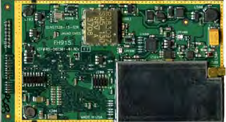
Figure 2-1. FH915
FH915 supports two separate Application Data and Maintenance modes of single UART serial port. The
built-in software tools provide the wireless link testing, unit’s status and error statistics monitoring as well
as unit’s settings change over the air. The firmware of the FH915 radio transceiver resides in a flash
memory. The updating of the radio transceiver programs is entirely software-based. The flash memory is
re-programmable through an UART interface or over the air.
The FH915 is developed for exacting customer needs and to have pin-to-pin compatibility with OEM
radios of JAVAD GNSS.
The Spread Spectrum transceiver is also capable of receiving RF signals through a 50 Ohm impedance
external antenna port.
The delivered product is a wireless system, which includes:
• FH915 – Spread Spectrum Radio Transceiver;
• AWLaunch – Windows based Unit Configuration and Maintenance Software Application running
on a IBM PC compatible computer and connecting to the device over RS-232 interface or USB-
to-Serial adapter.

Product Features
Operating at Spread Spectrum Band
12 www.javad.com
The setting can be done through the built-in Command Line interface (CLI), or through the configuration
and maintenance application software running either on PC – AWLaunch.
The diagnostic feature of the FH915 system provides the information to monitor and maintain user’s
communications link. The output transmit power, receive signal strength (RSSI), antenna/feedline
condition, and data decode performance are transmitted online without application interruption.
The product is designed for maximum performance and reliability even in the harshest environments.
Plug and play at its best, robust, withstanding the most adverse of conditions.
2.2. Operating at Spread Spectrum Band
The Spread Spectrum (SSR) technique in which a signal is transmitted on a bandwidth considerably
larger than the frequency content of the original information.
Spread-spectrum telecommunications is a signal structuring technique that employs direct sequence,
frequency hopping or a hybrid of these, which can be used for multiple access and/or multiple functions.
This technique decreases the potential interference to other receivers while achieving privacy. Spread
spectrum generally makes use of a sequential noise-like signal structure to spread the normally
narrowband information signal over a relatively wideband (radio) band of frequencies. The receiver
correlates the received signals to retrieve the original information signal.
2.3. Modulation Technique
FH915 radio transceiver uses two bands: 902-928 MHz ISM license free USA band and European CEPT
license free 868-870 MHz band. In 902-928 MHz band FH915 radio uses frequency hopping
transmission techniques.
The design is based on high-level modulation techniques which include:
The following are its key benefits:
• Ten optimized Frequency Hopping Patterns provides simultaneous operating of several units with
minimum of mutual interference.
• FEC coding scheme used with GMSK and 4FSK modulations is based on Convolutional code
• and the Viterbi decoding algorithm which is the most resource-consuming, but it does Maximum
likelihood decoding.
Modulation/ Channel Spacing 902.0-928.0
GMSK – Minimal Shift Keying with Gaussian Filtering 64.0 kbps, 128 *200.0 kHz
4FSK- Four Level Frequency Shift Keying (planned) 128.0 kbps, 128 *200.0 kHz

Product Features
Modulation Technique
Media Access Control (MAC)
13www.javad.com
In 868-870 MHz band the design is based on high-level modulation techniques which include
The following are its key benefits:
• FEC coding scheme used with GMSK and 4FSK modulations is based on Convolutional code and
the Viterbi decoding algorithm.
• Powerful FEC scheme used with JAVAD GNSS proprietary frame format improves the tolerance
to interference and ensures the highest link quality at distances range higher than 8 miles (13 km)
and roaming speeds of up to 60 mph (96 km/h).
2.3.1. Media Access Control (MAC)
The following Media Access protocols are available for FH915 modem:
1. Simplex protocols (Simplex Base, Simplex Remote, and Repeater) are developed primarily for
GNSS applications.
2. Half Duplex protocols (Half Duplex Base, Half Duplex Remote and Repeater) are the alternative
to Simplex protocols that provide bidirectional link with the dynamic bandwidth allocation.
Note: Repeater decreases the user data rate. The user data rate in the link with the repeaters is equal to C /
[(n+1]), where C is a link throughput determined by the modulation technique and n is a number of
repeaters in the chain. Half duplex Base, Half duplex Remote and repeater are not supported in current
release.
3. Sleep mode is an investment provided by MAC sub-layer that provides additional power saving.
The wakeup from Sleep mode is user selectable either by an internal real-time clock, or by an
external controller through the data interface control lines (RTS or DTR), or by SLEEP input line
(CMOS/TTL compatible input lines).
2.3.2. Operating Modes
The operating modes for FH915 can be set through the CLI, and/or through AWLaunch. The following
operating modes are available for FH915:
1. The sleep mode has automatic transmitter activation by an internal real-time clock, or by an
external controller through the data interface control lines (RTS and DTR), or by the triggering of
the external Sense Inputs.
2. Adaptive RF Power control used by Remotes minimizes the transmit power levels and
interference to co-channel and adjacent channel users. It also reduces the Remote’s power
consumption.
Modulation/ Channel Spacing 12.5 kHz 20 kHz 25 kHz
GMSK – Minimal Shift Keying with Gaussian Filtering 4.8 kbps 7.5 kbps 9.6 kbps
4FSK- Four Level Frequency Shift Keying (planned) 9.6 kbps 15 kbps 19.2 kbps
Product Features
Modulation Technique
Management Tools
14 www.javad.com
2.3.3. Management Tools
The built-in management tools along with AWLaunch (configuration and monitoring software
application) will provide the following benefits:
1. Easy user’s interface for system configuration and monitoring using well developed CLI or
intuitive GUI.
2. An ability to monitor status, alarms and radio performance through the intuitive GUI.
3. Software upgrades and improvements can be downloaded from AWLaunch to the units connected
with PC/PDA.
2.3.4. Security
The system provides wireless media access protection as well as data scrambling. The following are its
key features and benefits:
1. The Key Sequence generated by Pseudo-random generator scrambles the fully formatted frame
(including Frame’s CRC). This provides the wireless media access protection.
2. User selectable Frequency Hopping Pattern provides another level of the wireless media access
protection. At the same time it allows operators to increase the number of links deployed in the
same location.
Chapter 3
15www.javad.com
CONNECTION
3.1. FH915 connection
The FH915 connected directly to Evaluation Kit (p/n 99-571010-01) by its 16-Lead Header Connector,
ECS Corp., as it shown on the Figure 2-1.
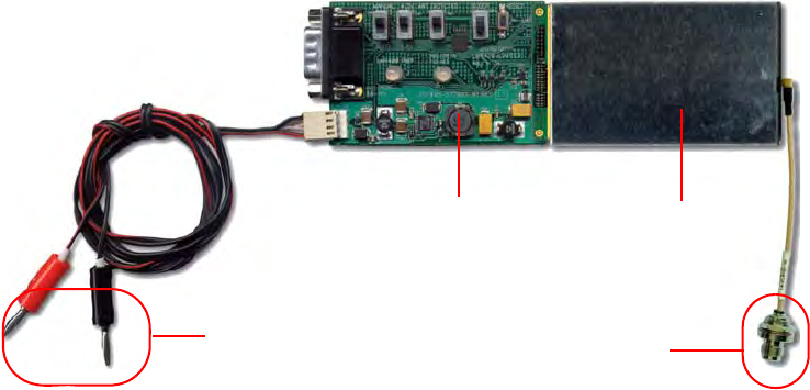
Figure 3-1. FH915 connected to Evaluation Kit
3.2. Antenna connection
The FH915 may be connected to external antenna using TNC to MMCX RA Antenna cable (included in
the Kit).
3.3. Power connection
The FH915 powered through Evaluation Kit and Power Cable (included in Kit). The Banana plugs of
power cable may be connected to any available laboratory power supply, battery or other power source
with power parameters, suitable for particular FH915 power specifications.
C
AUTION
:
Evaluation Kit does not provide any over-voltage protection. Connecting Evaluation Kit to voltage
exceeding particular FH915 power voltage range may cause damage of FH915 and Evaluation Kit
board.
to Antenna
to Power Supply
6-20 V DC, 1A
OEM Board
Adapter

Connection
Serial RS-232 connection
16 www.javad.com
C
AUTION
:
Evaluation Kit provides reverse polarity protection only in voltages range, specified for particular
FH915.
3.4. Serial RS-232 connection
A standard Null-Modem cable (included in Kit) with DB-9 Female connectors on both ends may be used
to connect PC COM_X port with Serial port on adapter.
Adapter’s DB-9 male connector external view and pinout is shown on the Figure 3-2.
Figure 3-2. DB-9 Male connector
Table 3-1. DB-9 Male Connector Specification
Please, refer to particular external device Serial port specification to select and use right Serial cable for
proper connection.
Pin Signal Name Dir Description
1 - - Not used
2 RXD I Receive Data
3 TXD O Transmit Data
4 DTR O Data Terminal Ready
5 GND - Signal Ground
6 DSR I Data Set Ready
7 RTS O Request To Send
8 CTS I Clear To Send
9 - - Not used
Chapter 4
17www.javad.com
COMMAND LINE INTERFACE
The built-in user-friendly Command Line Interface (CLI) allows user to perform a full configuration of
the unit and read the statistics and alarm status. It is the most powerful tool to configure the unit. It makes
changes to all possible settings that system will not be able to determine automatically.
The CLI commands allow user to configure and reconfigure the unit’s settings. The user configuration
parameters that could be changed through the CLI are:
• Data Port Settings
- Baud Rate
- Data Bits (8, 7)
- Parity (Odd, Even, None)
- Flow control (None or RTS/CTS)
• Alarm Settings
• Radio Operation Modes
• Sleep modes
- On/Off
- Activate by internal real-time clock
- Activate through RTS/CTS lines
- Activate by external sense lines
- Activate by any combination of the parameters mentioned before
Note: The unit’s configuration that is set or modified through the CLI will be lost after unit’s reboot, unless the
saving operation is used to store a new setting in the unit’s configuration file.
The CLI commands also provide filing operations, which include:
• Downloading
- Unit’s Configuration files
- Software Images
• Uploading Unit’s Configuration files
• Saving into the configuration files the configuration parameters modified through the CLI.
4.1. Command Line Interface Convention
The following convention is implemented in FH915 Command Line Interface (CLI):

Command Line Interface
Command Line Interface Convention
Software Switching to Maintenance Mode
18 www.javad.com
• The Carriage Return/Line Feed (CR/LF, 0x0D/0x0A) is a command delimiter. Command
delimiters CR or LF or CR+LF are valid.
• The Carriage Return/Line Feed (CR/LF, 0x0D/0x0A) is a reply delimiter followed by the “CLI>”
prompt if Echo option is On.
• The Carriage Return/Line Feed (CR/LF, 0x0D/0x0A) is a reply delimiter if Echo option is Off
(default option).
• The 2-digit number followed by “@” in the unit’s reply indicates the error code (refer to Table 4-
1 for description), if Echo Off is selected, otherwise the error message is displayed.
• A successfully performed command is replied by @00 code, if Echo Off is selected, otherwise the
set value is replied.
• A command with the certain [Parameter Name] and blank [Parameter List] displays the current
settings for a given parameter.
• To set the mode ordered by CLI commands as permanent User Setting (the setting automatically
selected for the boot-up unit) the SAVE command must be asserted.
• [/?] orders to show the help information for the given command.
• Commands are not key sensitive; small, none capital characters can be used to enter CLI
commands.
Table 4-1. Command Line Interface Error Codes
4.1.1. Software Switching to Maintenance Mode
Software Switching to Maintenance Mode can be utilized if Data/Maintenance Port (DP/MP) control line
is set to High Z (or 3.3v) level. To switch to Maintenance mode the special byte-sequences with special
meanings are used:
• Escape-Sequence: “+++” with 20 ms guard time before and after the command characters
• Escape-Acknowledge: “@00<CR><LF>” 20 ms toggling on CTS control line needed to
acknowledge switching from Data to Maintenance mode and vice versa. In Maintenance mode,
the unit’s serial port must keep CTS line always active.
Error Code Short Description
0x01 Command Syntax Error. A command followed by “/?” displays a command usage.
0x02 The parameter has a format error. A command with the certain [Parameter Name]
followed by “/?” displays the format and range of the variable.
0x03 The parameter is out of allowed range. A command with the certain [Parameter
Name] followed by “/?” displays the format and range of the variable.
0x04 The command is not valid for specific radio model. To display the list of available
commands, the HELP command must be used (see “Software Switching to
Maintenance Mode” ).
0x05 Unspecified Error
Command Line Interface
Command Line Interface Convention
Hardware Switching to Maintenance Mode
19www.javad.com
Happy Flow
1. In data-mode the unit starts looking for the Escape-sequence if there is no data from DTE for
more than 20 ms (Start Guard Time).
2. If the unit detects the Escape-Sequence:
• The transmitter continues sending over the air the data received from DTE before Escape-
Sequence and buffers the data from DTE;
• The Receiver immediately stops forwarding to DTE the data received over the air and buffers it
instead.
3. The radio unit waits for 20 ms and then sends Escape-Acknowledge to DTE if there is no data
from DTE during 20 ms of Stop Guard Time.
4. The unit goes to Maintenance mode and discards Escape-Sequence from input buffer. The modem
is immediately ready to receive commands. At the same time it continues buffering the data
received over the air since step 2.
Escape-Sequence in Data
During its waiting in step 3, the unit receives data from DTE:
• The unit sends buffered Escape-Sequence from DTE to the air;
• The unit sends all buffered data received from the air since step 2 to DTE and stays in data-mode
(i.e. transmits data received from DTE over the air – including the just received, unexpected, data
and forwards data received over the air to DTE.)
4.1.2. Hardware Switching to Maintenance Mode
As alternative to Software Switching, the switching through the MP/DP control line can be used (this
control line can be also used as Data Terminal Ready, DTR). To set Maintenance mode, the DTE must
assert DTR signal active (0v level). By falling edge of DTR signal the unit goes to Maintenance mode and
then sends Escape-Acknowledge to DTE („@00<CR><LF>“).
20 ms toggling on CTS control line followed by Escape-Acknowledge response is needed to
acknowledge switching from Data to Maintenance mode and vice versa. In Maintenance Mode, the unit’s
serial port must keep Clear to Send (CTS) line always active (see also “MPORT” on page 22).
Note: The powered up radio modem by default goes to Data Mode regardless of DTR control line polarity.
4.1.3. Switching to Data Mode
• DTE sends the CLI command “DATAMODE<CR>” or „DATAMODE<LF>” to the unit.
Note: Command “DATAMODE<CR><LF>“will be accepted as command “DATAMODE<CR>” and Data
Byte=0x0A.

Command Line Interface
Networking Commands
CONNECT
20 www.javad.com
• Unit answers with Escape-Acknowledge („@00<CR><LF>“) and immediately goes to datamode,
so that the DTE can start sending data as soon as the Escape-Acknowledge has been received.
• If no valid CLI commands received from DTE within 1 minute, the unit will automatically switch
back to data-mode.
Note: The data received over the air could be lost due to Rx buffer overflow if the unit stays in Maintenance
mode longer then 15 second.
4.2. Networking Commands
4.2.1. CONNECT
To connect the radio unit through the local maintenance serial port or to establish the link with the remote
unit in the Point-to-Multipoint network, the CONNECT command must be used.
CONNECT [Unit_Numb] [/?]
Where the Unit_Numb is an assigned decimal number for the unit to be connected. To get the complete
unit list, the CONNECT command must be used with no parameter. The list of units in the Point-to-Point
link with the connection established with remote unit is shown in Figure 4-1:
Figure 4-1. Connection List
To disconnect from the remote unit and connect to the local unit, the parameter (Unit_Numb) must be
equal to 0x00.
4.2.2. LINK
The LINK command is responsible for configuring radio’s operation mode. It has six parameters listed
below.
LINK [Parameter Name] [Parameters List] [/?]
LINK commands are as common so specific for two bands: 902-928 MHz band and 868-870 MHz band.
Commands common for two bands:
Unit Serial Number Connect
BS 003578659922
1 003574459923 C
Parameter Name Parameter List
FEC 0 – Disable Forward Error Correction, a default setting (see note below)
1 – Enable Forward Error Correction (see note below)
FHOP (0-9) - Frequency Hoping Pattern numbers for USA;
(10-19) - Frequency Hoping Pattern numbers for Australia;

Command Line Interface
Networking Commands
LINK
21www.javad.com
Note: LINK FHOP and LINK CHAN commands can be processed only if Frequency Map is defined.
Auto-scanning may not start automatically, only when scanning requested via CLI command (see LINK
CHAN 0 and STATE commands).
“Half Duplex” Base and “Half Duplex” Remote protocols are not supported in current release. LINK
ADDR and LINK CLKCORR commands are not recommended for using on site of End Users.
Commands specific for 902-928 MHz band:
Commands specific for 868-870 MHz band:
MOD 5 - GMSK, a default settings
6 - 4FSK;
PWRB / PWRW 0 – Automatic Transmit Power control, a default setting for Remote units
(15 – 30) / (30 – 1000) – RF output Power in dBm / mW
PWRB / PWRW (15 – 30) / (30 – 1000) – RF output Power in dBm / mW
RTR 0 – No Retransmission in the wireless cluster
1 – There is Repeater in the wireless cluster, valid for Base only
SCRAM 0 – No Scrambling (a default setting)
(1 – 255) – Seed for Pseudo-Random Sequence Generator
FEC 0 – Disable Forward Error Correction (FEC), a default setting
1 – Enable Reed-Solomon encoding
CHAR (0 – 255) – defines the ASCI code of the symbol indicating the end of a data
chunk of “Transparent w/EOT Character” protocol.
Parameter Name Parameter List
Parameter Name Parameter List
PWRB / PWRW 0 – Automatic Transmit Power control, a default setting for Remote units
(15 – 30) / (30 – 1000) – RF output Power in dBm / mW
PTRN 0…9 - Frequency hopping in ISM license free USA 902-928 MHz band;
10…19 - Frequency hopping in ISM license free 902-928 MHz band specified for
Australia;
Parameter Name Parameter List
CHAN Selects the Channel Number: CN = 1 to 32. Each Channel is defined by three
parameters: Carrier Frequency, Channel Spacing and Allowed Output Power level. CN
= 0 is reserved to set up the Frequency Automatic scanning mode. The LINK CHAN 0
command also forces the radio modem to continue scanning starting from the channel
currently selected by automatic scanning algorithm. In Automatic scanning mode, to
check the channel currently used or scanned, the STATE command must be used
PROT 1 - “Simplex Receiver” a default setting (see note below) 2 - “Simplex Transmitter” 3
- “Half Duplex” Base (reserved) 4 - “Half Duplex” Repeater (reserved)
9 - “Transparent w/EOT” Repeater (used with GMSK and 4FSK) 10 - “Repeater”
(JAVAD GNSS Proprietary Simplex)
12 - “Transparent w/EOT” Receiver (used with GMSK and 4FSK) 13 - “Transparent
w/EOT” Transmitter (used with GMSK and 4FSK)
17 - “Fast Sync” Receiver (used with GMSK and 4FSK) 18 - “Fast Sync” Transmitter
(used with GMSK and 4FSK) 19 - “Transparent w/EOT Character” Receiver (used
with GMSK and 4FSK) 20 - “Transparent w/EOT Character” Transmitter (used with
GMSK and 4FSK)

Command Line Interface
Serial Interfacing Commands
DPORT
22 www.javad.com
Note: The frequency defined by CHAN parameter is not valid if Frequency Hoping mode is selected. “Half
Duplex” Base and “Half Duplex” Remote protocols are not supported in current release.
4.3. Serial Interfacing Commands
4.3.1. DPORT
The DPORT is an object that responsible for data port interface configurations like Bit Rate, Flow
Control, etc.
DPORT [Parameter Name] [Parameters List] [/?]
4.3.2. MPORT
The MPORT is an object that responsible for maintenance serial port interface configurations such as data
rate and number of bits in a byte.
MPORT [Parameter Name] [Parameters List] [/?]
Parameter Name Parameter List
RATE 0 – Maintenance Port baud rate, a default setting
1 – 1200 baud
2 – 2400 baud
3 – 4800 baud
4 – 9600 baud
5 – 14400 baud
6 – 19200 baud
7 – 38400 baud
8 – 57600 baud
9 – 115200 baud, a default setting
BITS Set number of bits in one byte (8 or 7)
8 is a default setting
PARITY 0 – None, a default setting
1 – Odd
2 – Even
FLOW 0 – None
1 – Not used
2 - HW (RTS/CTS), a default setting
Parameter Name Parameter List
RATE 0 – Auto.
1 – 1200 baud
2 – 2400 baud
3 – 4800 baud
4 – 9600 baud
5 – 14400 baud
6 – 19200 baud
7 – 38400 baud
8 – 57600 baud
9 – 115200 baud, a default setting

Command Line Interface
Special Commands
ALARM
23www.javad.com
Note: JAVAD GNSS radio modem’s does not support data flow and parity on the maintenance serial port.
MPORT operates using 8 bits in one byte fixed (not configurable).
The radio modem with none-dedicated maintenance serial port must keep CTS line always active in
MPORT mode (DP/MP is low).
4.4. Special Commands
4.4.1. ALARM
The ALARM command is intended to set up the alarm indication mode and alarm control lines’ behavior.
ALARM [Parameter Name] [Parameters List] [/?]
The Alarm LED must indicate the SYNC Loss and BER exceeding the defined threshold.
Note: The BERTH 1 / 2 is optional for TTL2 = 3 condition, otherwise the BERT alarm is off
4.4.2. BOOT
The BOOT command is intended to reboot the unit using selected user settings. Two options are
available, to use the default user settings defined by dealer or to use the settings defined by end-user
BOOT [Parameter Name] [Parameters List] [/?]
The BOOT command with no parameters selects the user settings defined by the prior “parameterized”
BOOT commands.
4.4.3. HELP
The HELP command types the list of all available commands:
HELP – Display this usage
Parameter Name Parameter List
TTL1 0 – TTL_OUT1 = logic “1”
1 – TTL_OUT1 = TTL_IN, received from remote unit (default settings)
TTL2 0 – TTL_OUT2 = logic “1”
1 – TTL_OUT2 = TTL_IN2, received from remote unit (default settings)
2 – TTL_OUT2 = SYNC Loss
3 – TTL_OUT2 = BER > BERTH or SYNC Loss
BERTH 1– BER Threshold >10 –3 (default threshold level for BER)
2 – BER Threshold BER >10 –2
Parameter Name Parameter List
CFG 0 – selects the default user settings
1 – selects user modified settings

Command Line Interface
Special Commands
SAVE
24 www.javad.com
BOOT – Reboot the unit
LINK – RF Link Operation Mode
DPORT – Data Port Configuration
MPORT – Maintenance Port Configuration
ALARM – Alarm Indication and Alarm Control Configuration
SLEEP – Sleep Mode Configuration
CONNECT – Connect to Specified Unit
STATE – Display Status and Statistics
SAVE – Save Current Configuration into Configuration File
INFO – Display Product ID along with Hardware/Software Versions
DATAMODE – Exit Maintenance Mode
[COMMAND] /? – Display Command Usage
4.4.4. SAVE
The SAVE command is intended to store the unit’s currently used configuration into the User
Configuration file. The configuration stored in the User Configuration file is activated by automatically
after unit’s reboot.
4.4.5. SLEEP
The SLEEP command determines the sleep mode parameters. The sleeping FH915 can be activated by
real-time CLK, DTR/RTS lines, and command received through TTL inputs. The user can select one,
two, or all three conditions.
SLEEP [Parameter Name] [Parameters List] [/?]
Parameter Name Parameter List
CLK 0 – Do not activate by internal real-time clock
(1 – 255) – Activate by internal real-time clock after 100 to 25500 msec of sleeping
HW 0 – Do not activate through DTR/RTS lines
1 – Activate through DTR/RTS lines
TTL 0 – Do not activate by external sense lines
1 – Activate by external sense lines
GTS 0 – Disable Sleep mode (default)
(1 – 255) – Go to sleep mode if there is no activity in 10 to 2550 msec

Command Line Interface
Diagnostics and Identification Commands
INFO
25www.javad.com
4.5. Diagnostics and Identification Commands
4.5.1. INFO
The INFO command is used to retrieve the Radio ID along with its Hardware version, the loaded real-
time software version/revision and BootLoader’s version/revision.
INFO [Parameter Name] [Parameters List] [/?]
The INFO command without Parameter Name indicates all values:
FH915 Spread Spectrum Radio Modem.
Product ID =41
S/N = 11327
Hardware =2.0
Firmware =2.1.9
BootLoader =4.03
4.5.2. STATE
The STATE command is used to check the state of the wireless link, the unit in the link, and the alarm
control lines. To specify a radio unit (local or remote), the CONNECT command must be used in prior of
STATE command using.
STATE [Parameter Name] [Parameters List] [/?]
The STATE command without Parameter Name indicates all values:
Parameter Name Parameter List
ID Product ID
SN Six bytes Serial Number (SN)
HW 1.0 – hardware revision
FW Ver. 1.0 Rev. A – displays software’s version in numeric “Major.Minor” format and
revision in numeric format (range from 01 to 99) for engineering releases and alphabetic
format (A to Z) for manufacturing releases
BL BootLoader Version
Parameter Name Parameter List
TTL1 0/1 – State of TTL_IN1 line
TTL2 0/1 – State of TTL_IN2 line
RSSI -52 to -116 dBm – Indicates the Receive Signal Strength in dBm
BER 1.0E-6 to 9.9E-3 – Indicates the BER level
FREQ 902.000000 to 928.000000 MHz – Displays the central frequency of the
operating channel
CHAN 1 to 9601 – Displays the selected or currently scanned frequency channel
TEMP -30°C to 100°C – Displays the temperature inside of enclosure
Command Line Interface
Diagnostics and Identification Commands
STATE
26 www.javad.com
TTL_IN1 = 0
TTL_IN2 = 1
RSSI = -110 dBm
BER = < 2.3E-5
FREQ = 910.000000 MHz
CHAN = 10
TEMP = 70C
Note: The indicated receive signal strength (RSSI) is equal to -147 dBm if there is no signal received from
transmitter.

Appendix A
27www.javad.com
TECHNICAL SPECIFICATIONS
FH915 DSP based integrated Spread Spectrum Modem is the single board OEM wireless transceiver
intended for SCADA, outdoor telemetry applications and transmission /receiving of differential
corrections and additional information by terrestrial radio channels between two GNSS receivers.
The Spread Spectrum module provides half-duplex communication with transmitter output power of 1 W
(+30 dBm) in the frequency band 902-928 MHz z. In 868-870 MHz band module provides half-duplex
communication with transmitter output power up to 1W (+30 dBm) with channel spacing 25.0/ 20.0/12,5/
6.25 kHz. It supports the following modulation methods: GMSK, 4FSK.
A.1. Technical Specifications
A.1.1. Radio Transceiver
Table A-1. Radio Transceiver Specifications
A.1.2. Radio Transmitter
Table A-2. Radio Transmitter Specifications
Component Details
Frequency Range 902-928 MHz (USA)
915-928 MHz (Australia)
868-870 MHz (EU) with 25/20/12.5 kHz CS
Link Rate, symbols/second 9600, 19200, 38400, 64000 (USA/Australia)
4800, 9600 (EU)
Carrier Frequency Stability ±1 ppm
Modulation GMSK/4FSK
Communication Mode Half duplex, simplex, repeater
Component Details
Transmitter Output Power +10... +30 dBm in 1 dB step / 50 (USA/Australia)
+10...+27 dBm in 1dB step/50 (EU)

Technical Specifications
Technical Specifications
Radio Receiver
28 www.javad.com
A.1.3. Radio Receiver
Figure A-1. Radio Receiver Specifications
A.1.4. Modem
Figure A-2. Modem Specifications
Component Details
Receiver Sensitivity for GMSK
(BER 1x 10⁻⁴)
-110 dBm for 25 kHz CS
-110 dBm for 20 kHz CS
-112 dBm for 12.5 kHz CS
Receiver Dynamic Range -119 to -10 dBm
Component Details
Interface DSP UART (serial port)
Interface Connector 16-lead Connector
Data Speed of Serial Interface 9600 - 115200 bps
Data Rate of Radio Interface
(USA/Australia) 64000 bps - GMSK
32000 bps - GMSK
19200 bps - GMSK
16000 bps - GMSK
128000 bps - 4FSK
64000 bps - 4FSK
32000 bps - 4FSK
19200 bps - 4FSK
16000 bps - 4FSK
Data Rate Radio Interface
(25 kHz CS) 9600 bps – GMSK
19200 bps – 4FSK
Data Rate Radio Interface
(20 kHz Channel Spacing) 7500 bps – GMSK
15000 bps – 4FSK
Data Rate Radio Interface
(12.5 kHz Channel Spacing) 4800 bps – GMSK
9600 bps – 4FSK
Forward Error Correction (FEC) Convolutional code
Data scrambling Yes

Technical Specifications
Technical Specifications
Compliance
29www.javad.com
A.1.5. Compliance
A.1.6. General
Features
• DSP-Modem
• Multi-Modulation Technologies
• Zero-IF Technologies
• 902-928 MHz (USA), 915-928 MHz (Australia), 868-870 MHz (EU) Frequency Ranges
• Up to 115200 bps Serial Interface Data Rate
• Embedded Firmware Compensation for Operation at Extremely Low and High Temperatures
• Compact Design
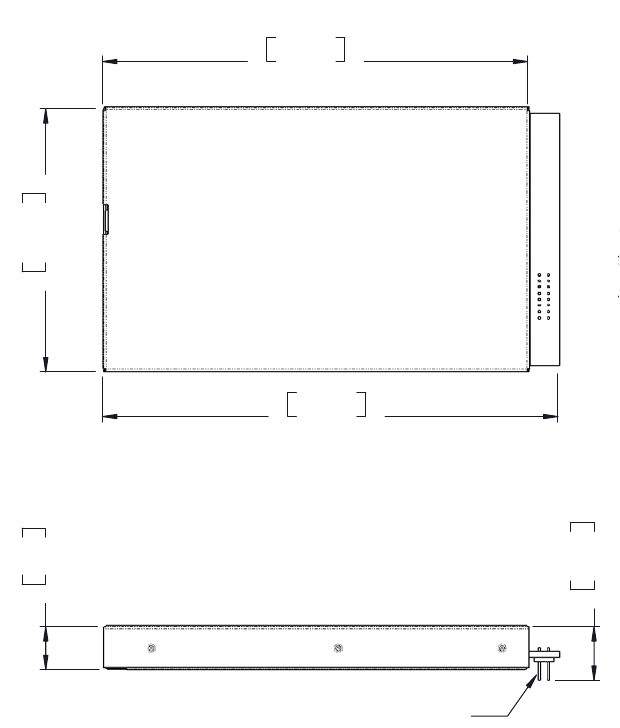
A.1.7. Mechanical Properties For End-product
Dimensions for PCB Mounted Enclosure:
80 mm x W: 46.5 mm x H: 7.6/9.5 mm (3.15" x 1.83" x 0.3")
Component Details
FCC FCC Part 15.247
ETSI EN 300 220-1, EN 301 489-1
Component Details
Input Voltage 4.0 V ± 5%
Power Consumption (average) 3 W – transmit with 50% duty cycle (1 W TPO)
1 W – receive mode
Operation Temperature -40oC - +60oC
Storage Temperature -40oC - +80oC
Dimensions L: 80 mm x W: 46.5 mm x H: 7.6 / 9.5 mm
Weight 43 g
Technical Specifications
External Connectors
Antenna Connector
30 www.javad.com
A.2. External Connectors
A.2.1. Antenna Connector
J2 is Antenna Input / Output Connector: MMCX RIGHT ANGLE PCB JACK, AMPHENOL P/N 908-
24100
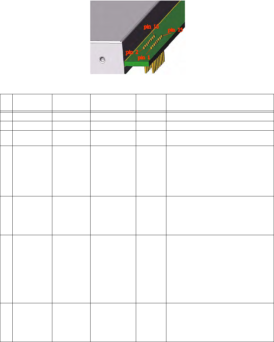
A.2.2. Main Connector
The user ports connector is used to provide connection with an external DTE or with the PC running
AWLaunch management software applications.
Note: The RS232-to-TTL adapter must be used to provide physical level compatibility between COM port of
PC running AWLaunch and FH915 user interface port.
9.50 mm
.37 in
7.6 mm
.3 in
Connector, 16-lead,
Thru-hole 2x8, Header,
".050"
75.00 mm
2.95 in
46.50 mm
1.83 in
80.00 mm
3.15 in
BOTTOM
SIDE
9.50 mm
.37 in
7.6 mm
.3 in
Connector, 16-lead,
Thru-hole 2x8, Header,
75.00 mm
2.95 in
46.50 mm
1.83 in
80.00 mm
3.15 in
BOTTOM
SIDE
Technical Specifications
External Connectors
Main Connector
31www.javad.com
16-Lead Header Connector, ECS Corp. P/N 9616-D1-01-03.
PIN
#
Signal
Designator Signal name Description I/O Comments
1 GND GND Ground - Signal and Chassis Ground
2 DSP UART 1 TXD Transmit Data TTL Input Serial Data Input
3 DSP UART 2 RXD Receive Data TTL
Output Output for received serial data
4 DPORT-5 DTR or DP/
MP Data Terminal
Ready TTL Input Control line can be used as a backup method
for entering Command mode: (0V) –
Maintenance Mode; (3.3V) – Data Mode
An internal 100K pull-up enables Data
Mode if this signal is left unconnected.
Maintenance Mode is
also accessible by transmitting an escape
sequence.
5 DPORT1 CTS Clear to Send TTL
Output Used to control transmit flow from the user
to the radio:
(0V) – Transmit buffer not full, continue
transmitting
(3.3V) – Transmit buffer full, stop
transmitting
6 TTLI1 SLEEP Sleeps/wakes
radio
Receive only
TTL Input In sleep mode, all radio functions are
disabled consuming less than 50µA. An
internal 10K pull-down wakes up the radio
if this signal is left unconnected. At wake
up, any user programmed configuration
settings are refreshed from flash memory,
clearing any temporary settings that may
have been set:
(3.3V) – Sleep Radio; (0V) – Wake Radio
As an option could be used as TTL Input
Line 1.
7 DPORT3 MDM_GRN Data Carrier
Detect TTL
Output Used by remotes to indicate that the remote
has successfully acquired the signal from
base station:
(0V) 1 – Carrier detected (synchronized)
(3.3V) 0 – No carrier detected (not
synchronized)

Technical Specifications
External Connectors
Main Connector
32 www.javad.com
8 DPORT4 RTS Request to Send TTL Input Gates the flow of receive data from the radio
to the user on or off. An internal 10K pull-
down enables data receive if this signal is
left unconnected. In normal operation, this
signal should be asserted:
(0V) – Receive data (RxD) enabled
(3.3V) – Receive data (RxD) disabled
9 DPORT2 DSR Data Set Ready TTL
Output Used to control transmit flow from the user
to the radio:
(0V) 1 – Receive buffer has data to transfer;
(3.3V) 0 – Receive buffer is empty
10 RES CONT RESCONT Reset Control TTL Input Reset the radio by shortening this pin to the
ground.
11 TTLO1 TTLOUT1 TTL Output Line
1TTL
Output Reserve line
12 TTLO2 TTLOUT2 TTL Output Line
2TTL
Output Reserve line
13 GND GND Ground - Signal and Chassis Ground
14 TTLI2 TTLIN TTL Input line TTL Input An internal 100K pull-up resistor is applied.
15 VCC36 PWR Power Supply External Regulated positive 4.0V DC from ext.
Power Supply.
16 VCC36 PWR Power Supply External Regulated positive 4.0V DC from ext.
Power Supply.
PIN
#
Signal
Designator Signal name Description I/O Comments
Appendix B
33www.javad.com
SPREAD SPECTRUM RADIO USAGE
Many countries require a license for radio users. Be sure you comply with all local laws while operating a
Spread Spectrum radio.
The quality and strength of the Spread Spectrum signals translates into range for Spread Spectrum
communications.
The system’s range will greatly depend on the local conditions. Topography, local communications and
even meteorological conditions play a major role in the possible range of communications.
Spread Spectrum Radio Usage
34 www.javad.com
Appendix C
35www.javad.com
SAFETY WARNINGS
Read these instructions.
• Keep these instructions.
• Heed all warnings.
• Follow all instructions.
• Clean only with a damp cloth.
• Do not block any of the ventilation openings. Install in accordance with the manufacturer's
instructions.
• Do not install near any heat sources such as radiators, heat registers, stoves, or other apparatus
(including amplifiers) that produce heat.
• Protect the power cord from being walked on or pinched particularly at plugs, convenience
receptacles, and the point where they exit from the apparatus.
• Only use attachments/accessories specified by the manufacturer.
• Refer all servicing to qualified service personnel. Servicing is required when the apparatus has
been damaged in any way, such as power-supply cord or plug is damaged, liquid has been spilled
or objects have fallen into the apparatus, or has been dropped.
• Apparatus shall not be exposed to dripping or splashing and no objects filled with liquids, shall be
placed on the apparatus.
C.1. General Warnings
This product should never be used:
• Without the user thoroughly understanding operator’s manual.
• After disabling safety systems or altering the product.
• With unauthorized accessories.
• Contrary to applicable laws, rules, and regulations.
D
ANGER
:
THE FH915 SHOULD NEVER BE USED IN DANGEROUS ENVIRONMENTS.
Safety Warnings
General Warnings
36 www.javad.com

Appendix D
37www.javad.com
WARRANTY TERMS
JAVAD GNSS electronic equipment are guaranteed against defective material and workmanship under
normal use and application consistent with this Manual. The equipment is guaranteed for the period
indicated, on the warranty card accompanying the product, starting from the date that the product is sold
to the original purchaser by JAVAD GNSS’ Authorized Dealers1.
During the warranty period, JAVAD GNSS will, at its option, repair or replace this product at no
additional charge. Repair parts and replacement products will be furnished on an exchange basis and will
be either reconditioned or new. This limited warranty does not include service to repair damage to the
product resulting from an accident, disaster, misuses, abuse or modification of the product.
Warranty service may be obtained from an authorized JAVAD GNSS warranty service dealer. If this
product is delivered by mail, purchaser agrees to insure the product or assume the risk of loss or damage
in transit, to prepay shipping charges to the warranty service location and to use the original shipping
container or equivalent. A letter should accompany the package furnishing a description of the problem
and/or defect.
The purchaser's sole remedy shall be replacement as provided above. In no event shall JAVAD GNSS be
liable for any damages or other claim including any claim for lost profits, lost savings or other incidental
or consequential damages arising out of the use of, or inability to use, the product.
1. The warranty against defects in JAVAD GNSS battery, charger, or cable is 90 days.

900 Rock Avenue, San Jose, CA 95131 USA
Phone: +1(408)770-1770
Fax: +1(408)770-1799
www.javad.com
Copyright © JAVAD GNSS, Inc., 2011
All rights reserved. No unauthorized duplication.