JAVAD GNSS HPT104 VHF Radio Transceiver User Manual Use Manual
JAVAD GNSS, Inc. VHF Radio Transceiver Use Manual
UserManual.wiki
>
JAVAD GNSS
>
HPT104 User Manual
Use Manual
Navigation menu
Upload a User Manual
Namespaces
Wiki Guide
HTML
PDF
Info
Views
User Manual
Discussion / Help
Navigation


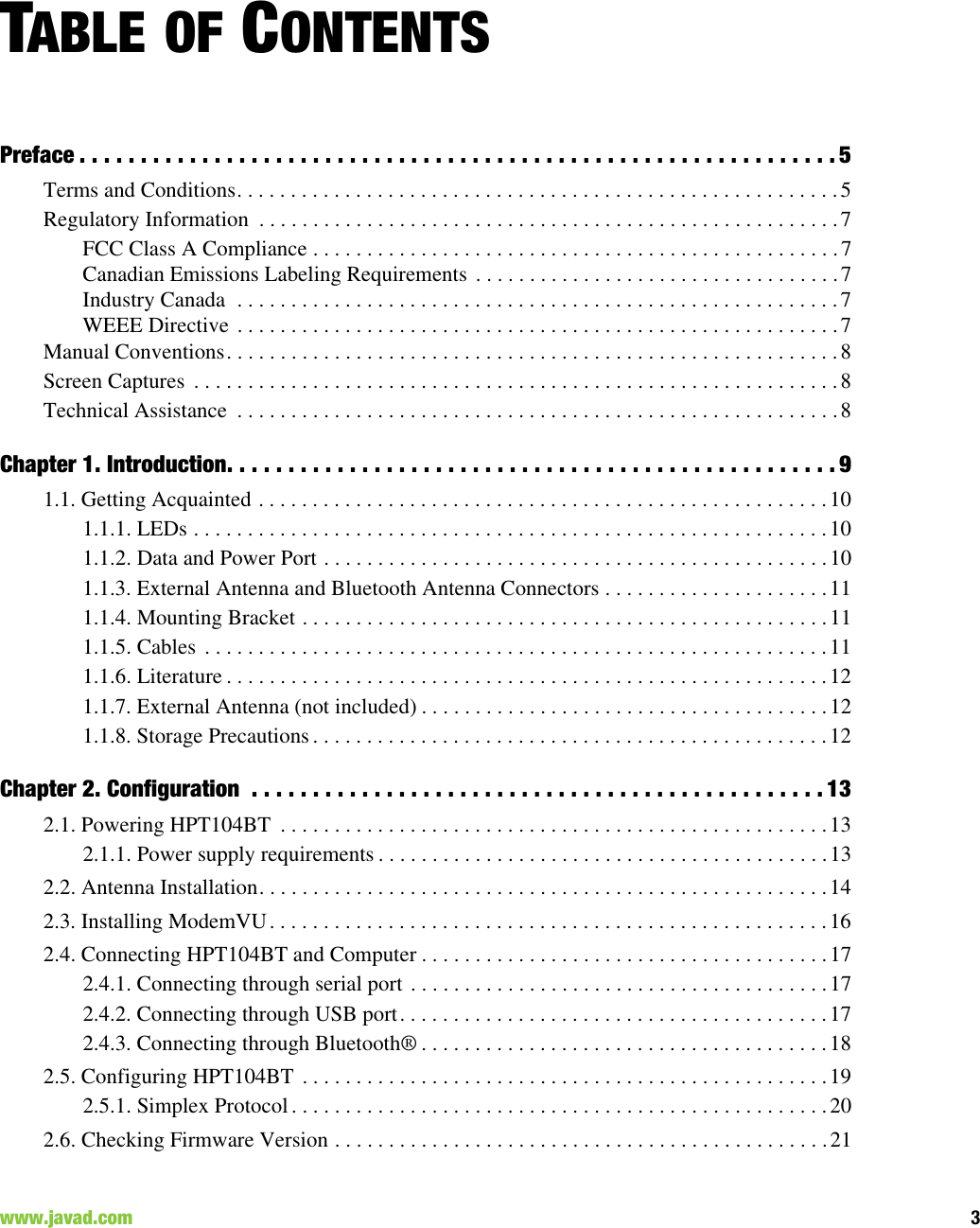

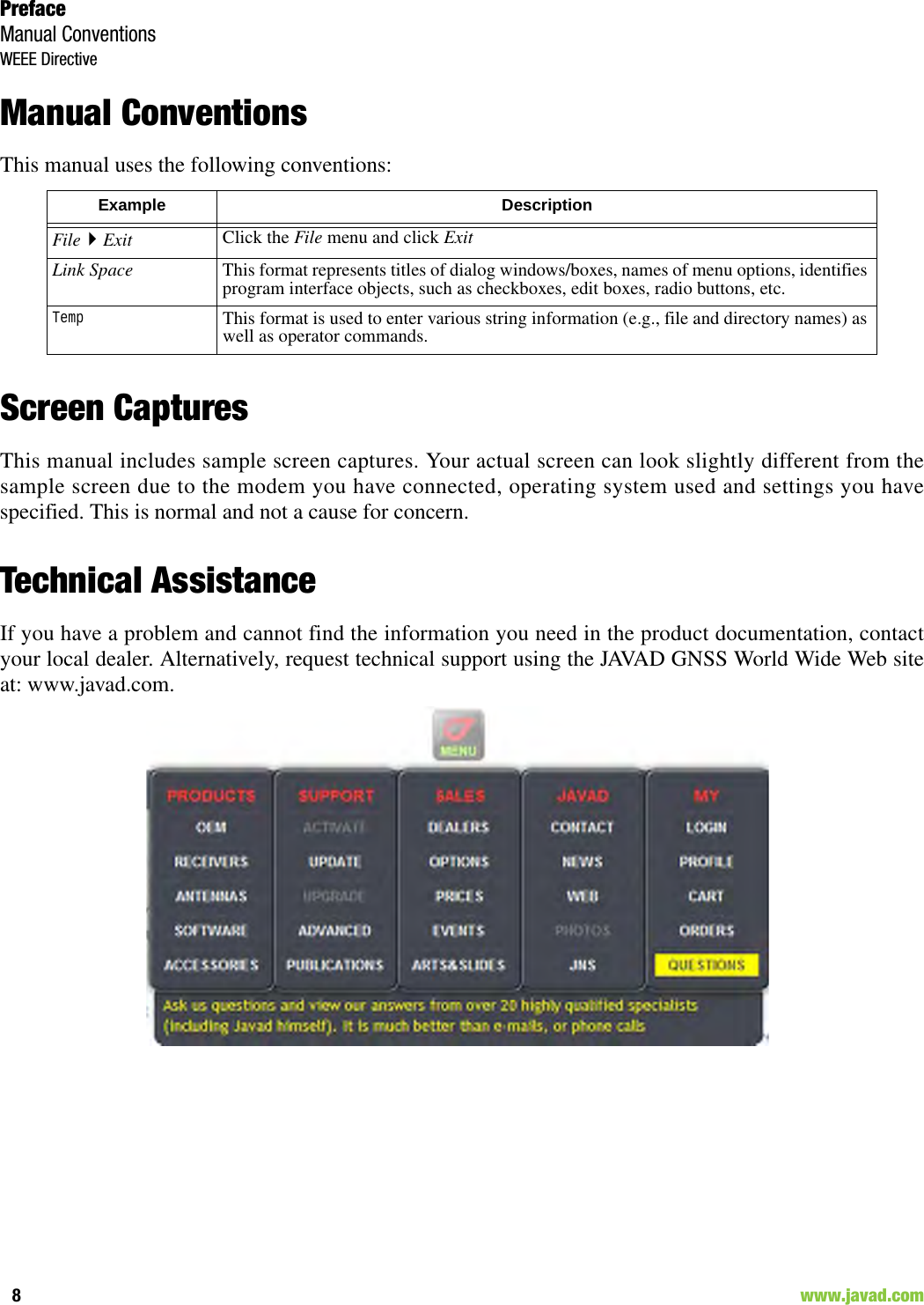
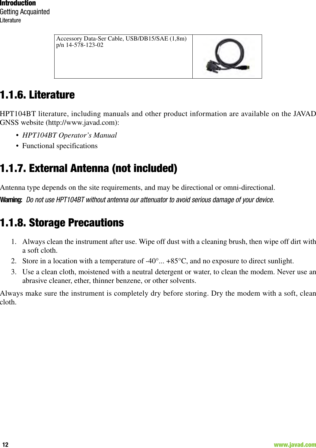


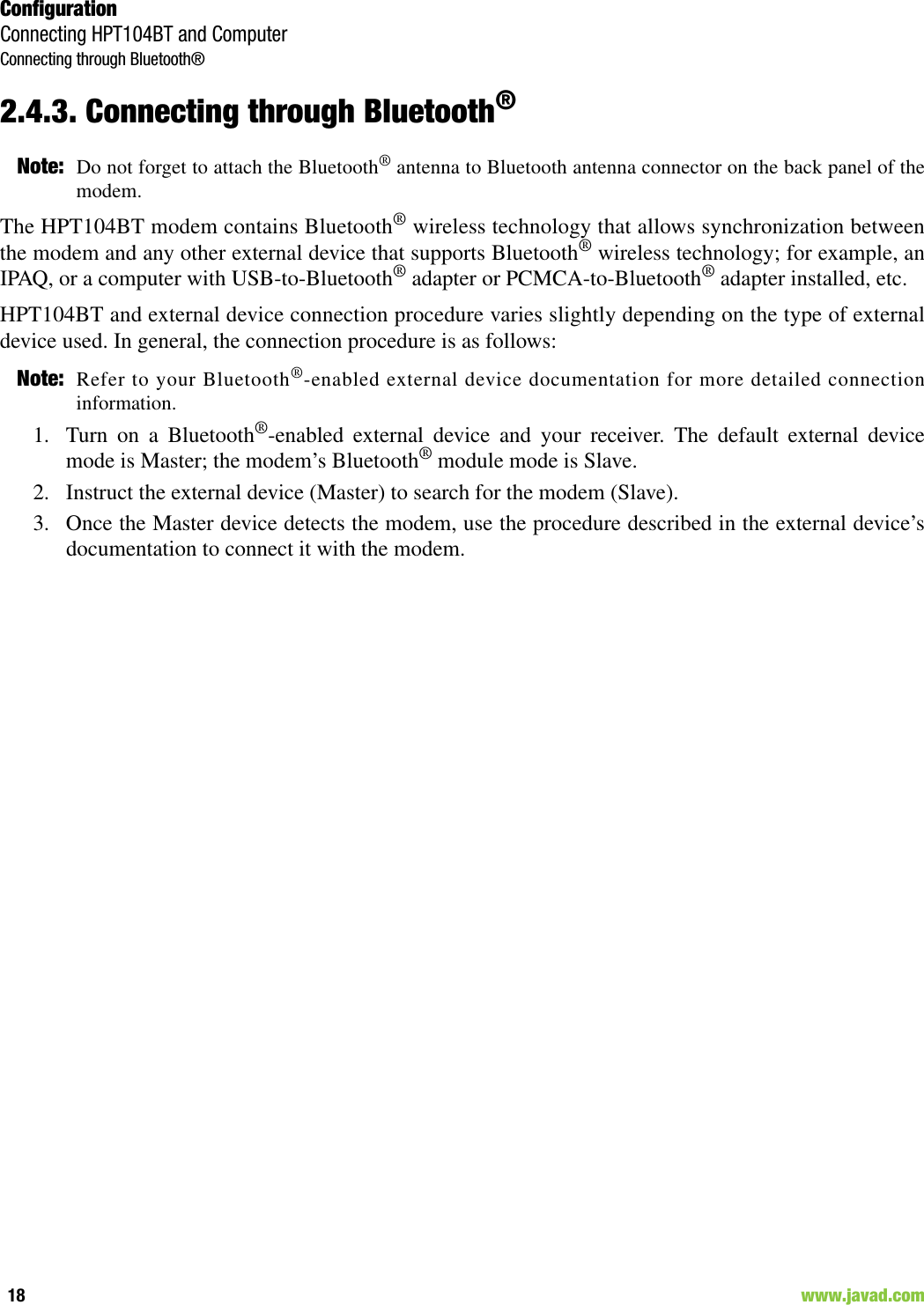
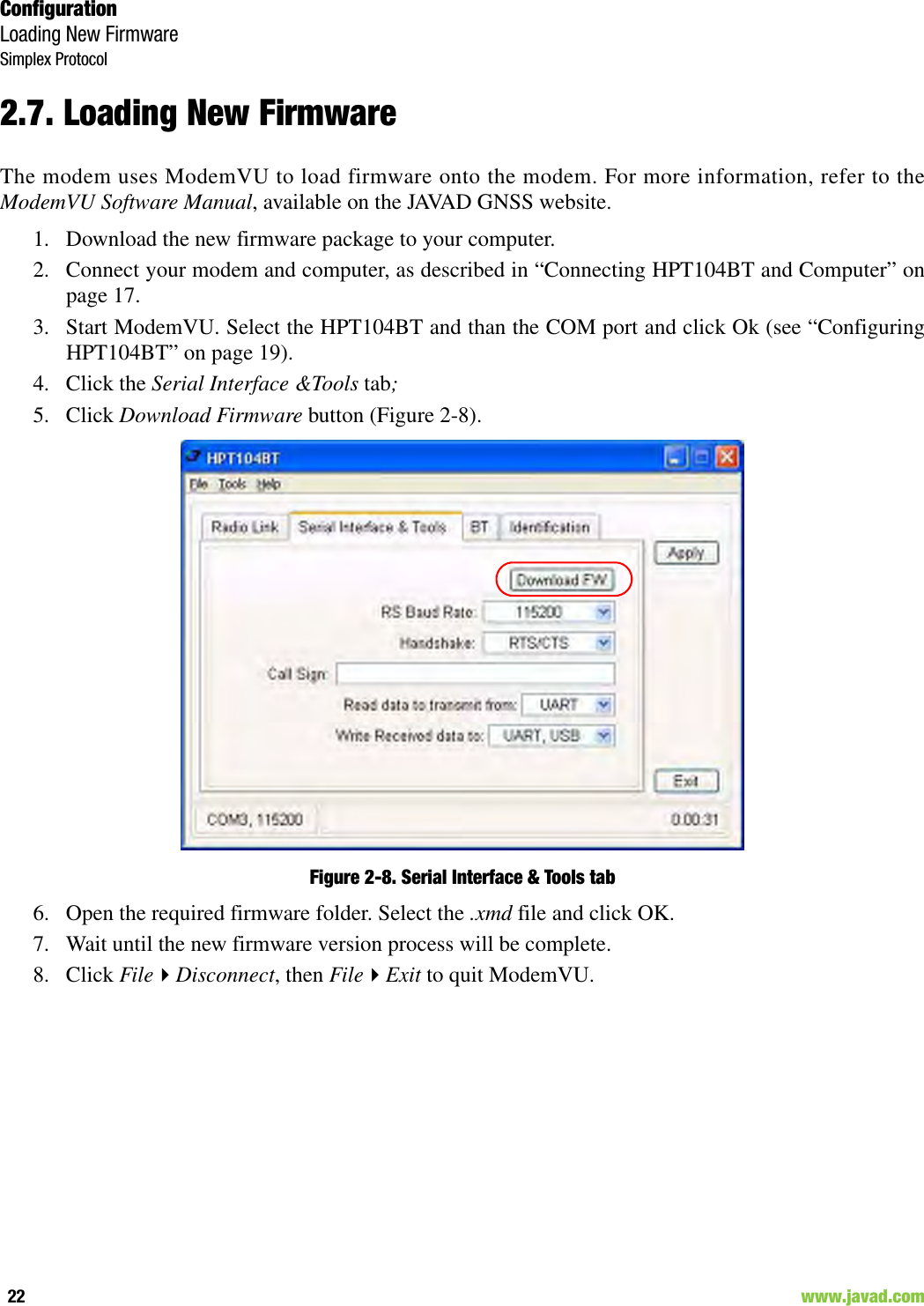

![Command Line InterfaceCommand Line Interface Convention26 www.javad.com3.1. Command Line Interface ConventionThe following convention is implemented in HPT104BT Command Line Interface (CLI):• The Carriage Return/Line Feed (CR/LF, 0x0D/0x0A) is a command delimiter.• The Carriage Return/Line Feed (CR/LF, 0x0D/0x0A) is a reply delimiter followed by the “CLI>”prompt if Echo option is On.• The Carriage Return/Line Feed (CR/LF, 0x0D/0x0A) is a reply delimiter if Echo option is Off(default option).• The 2-digit number followed by “@” in the unit's reply indicates the error code (refer to Table 3for description), if Echo Off is selected, otherwise the error message is displayed.• A successfully performed command is replied by @00 code, if Echo Off is selected, otherwise theset value is replied.• A command with the certain [Parameter Name] and blank [Parameter List] displays the currentsettings for a given parameter.• To set the mode ordered by CLI commands as permanent User Setting (the setting automaticallyselected for the boot-up unit) the SAVE command must be asserted.• A command followed by “/F” option displays the Parameters in the predefined frame format. Thedisplay frame format is unique for each command supporting “/F” option.Table 3-1. Command Line Interface Error CodesError Code Short Description0x01 Command Syntax Error. A command followed by “/?” displays a command usage.0x02 The parameter has a format error. A command with the certain [Parameter Name] followed by “/?” displays the format and range of the variable.0x03 The parameter is out of allowed range. A command with the certain [Parameter Name] followed by “/?” displays the format and range of the variable.0x04 The command is not valid for specific radio model. To display the list of available commands, the HELP command must be used.0x05 Unspecified Error](https://usermanual.wiki/JAVAD-GNSS/HPT104/User-Guide-1573423-Page-26.png)
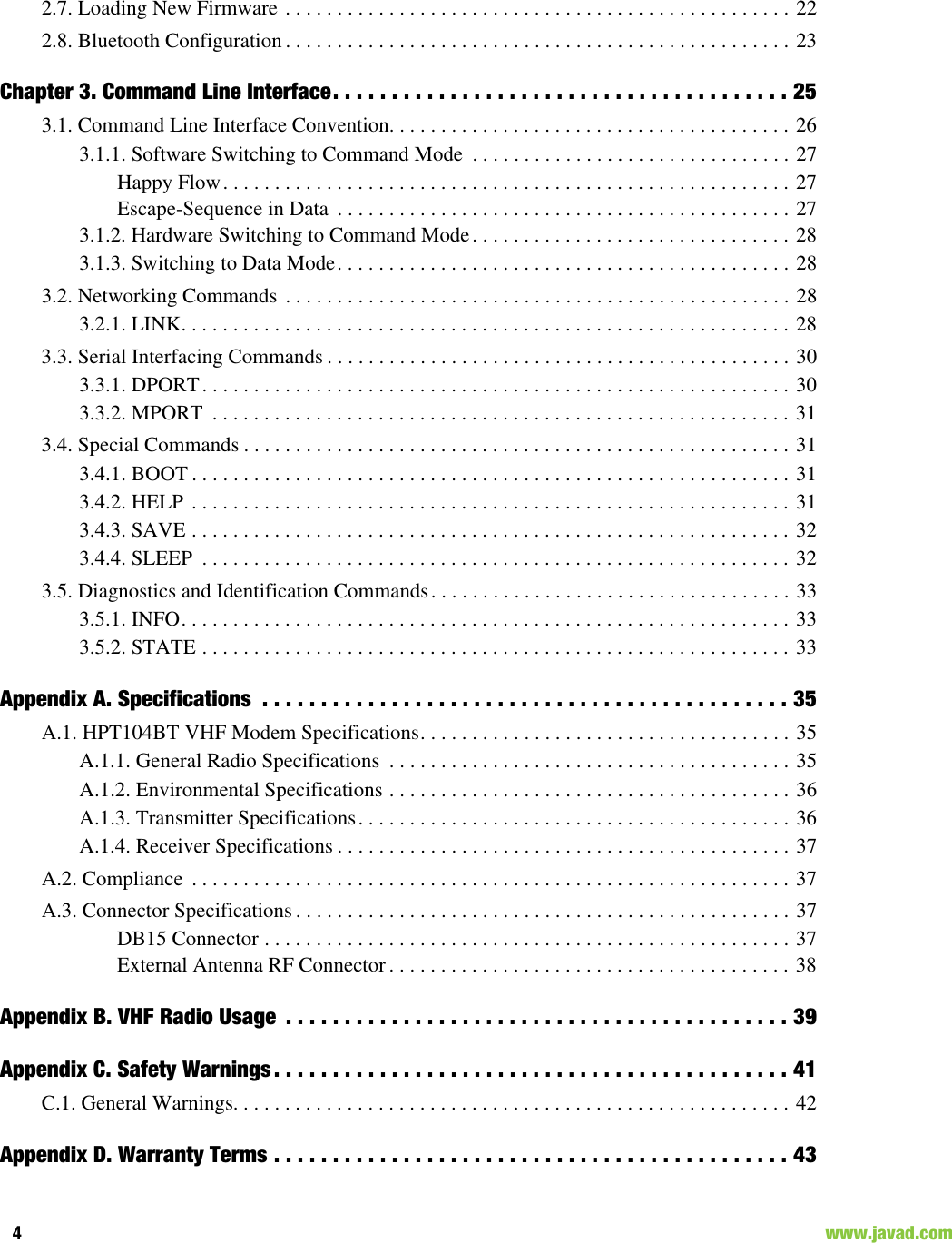
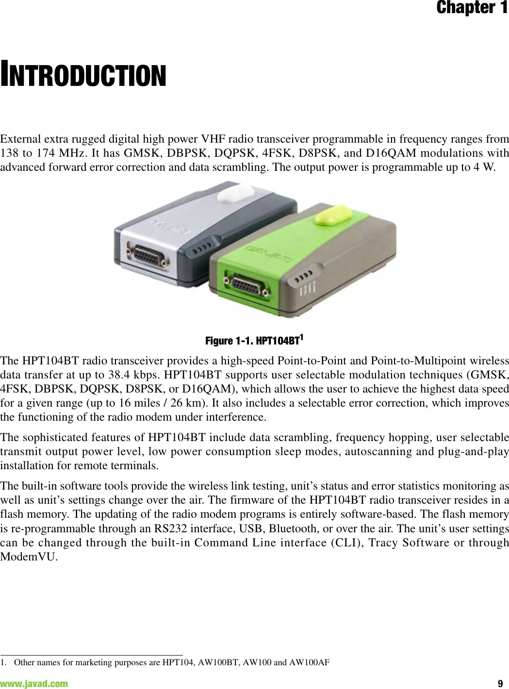
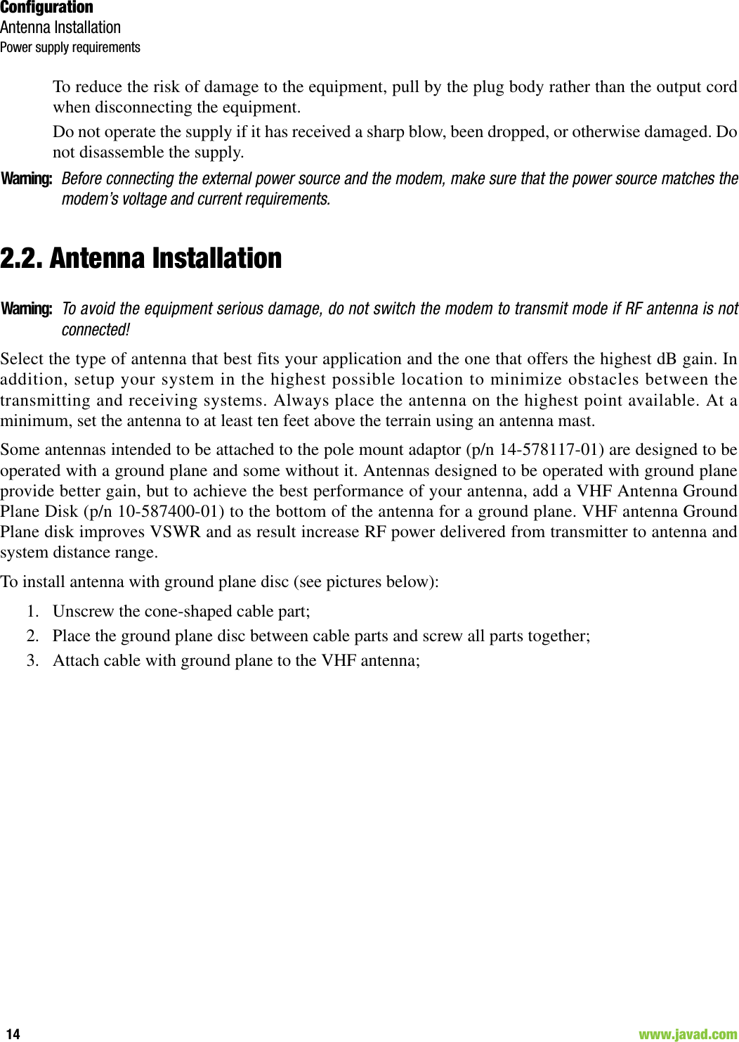
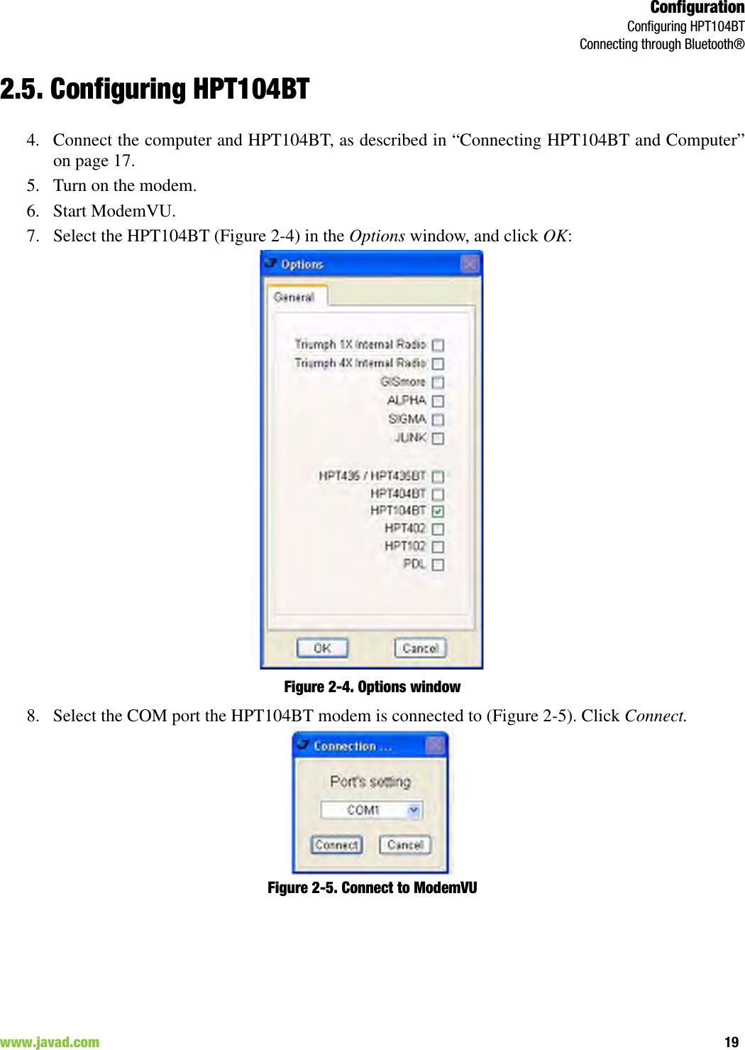
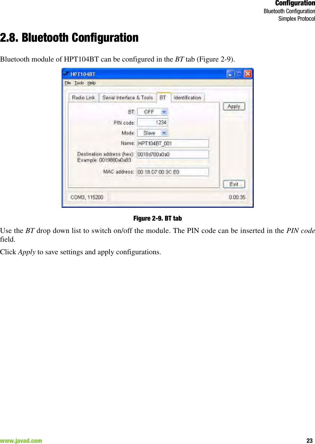
![Command Line InterfaceNetworking CommandsLINK29www.javad.com LINK [Parameter Name] [Parameters List] [/?]Note: The frequency defined by CHAN parameter is not valid if Frequency Hoping mode is selected.In the Frequency Hoping mode, the Frequency Pattern generator must generate the random numberssmaller than the number of frequencies listed in the unit's frequency list.Parameter Name Parameter ListPROT 1 - “Simplex Receiver”, a default setting for Remote units (for firmware version 1.8)2 - “Simplex Transmitter” (for firmware version 1.8)3 - “Half Duplex” specific for remote units (for firmware 3.0 and newer)4 - “Half Duplex” specific for base unit (for firmware 3.0 and newer)5 - Reserved for future use6 - Reserved for future use7 - “TRMB Receiver” (used with GMSK modulation, Trimble compatible) (for firmware version 1.8)8 - “TRMB Transmitter” (used with GMSK modulation, Trimble compatible) (for firmware version 1.8)9 - “Transparent w/EOT” Repeater (used with GMSK and 4FSK, Pacific Crest compatible) (for firmware version 1.8)10 - “Repeater” (JAVAD Proprietary Simplex) (for firmware version 1.8)11 - “TRMB Repeater” (used with GMSK modulation, Trimble compatible) (for firmware version 1.8)12 - “Transparent w/EOT” Receiver (used with GMSK and 4FSK modulation, Pacific Crest compatible) (for firmware version 1.8)13 - “Transparent w/EOT” Transmitter (used with GMSK and 4FSK modulation, Pacific Crest compatible) (for firmware version 1.8)14 - “STL Receiver” (used with 4FSK modulation, Satel compatible) (for firmware version 1.8)15 - “STL Transmitter” (used with 4FSK modulation, Satel compatible) (for firmware version 1.8)MOD 1 – DBPSK2 – DQPSK, a default settings3 – D8PSK4 – D16QAM5 – GMSK6 – 4FSKSPACE Sets channel spacing:0 - 25kHz, a default setting1 - 12.5kHz2 - 6.25kHz3 - 20kHzPWRB / PWRW (25 - 46) / (320 - 3500) - RF output Power in dBm / mWFHOP (only for firmware ver. 1.8) (0 - 32) - Frequency Hoping Pattern numberLINK FHOP command can be processed only if the Channel Map (up to 32 channels) SCRAM 0 - No Scrambling (a default setting)(1 - 255) - Seed for Pseudo-Random Sequence GeneratorFEC 0 - Disable Forward Error Correction (FEC), a default setting1 - Enable Reed-Solomon encodingRTR (only for firmware version 1.8)Base Unit 0 - No Retransmission in the wireless cluster1- There is RepeaterRemote Unit 0 - Auto Detect (Base or Repeater)1 - Receive from Repeater2 - Receive from Base](https://usermanual.wiki/JAVAD-GNSS/HPT104/User-Guide-1573423-Page-29.png)
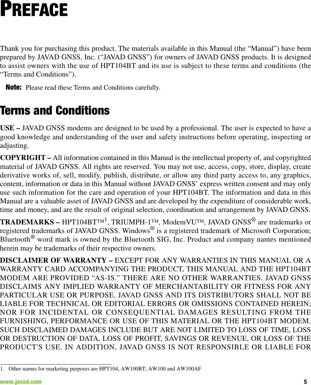
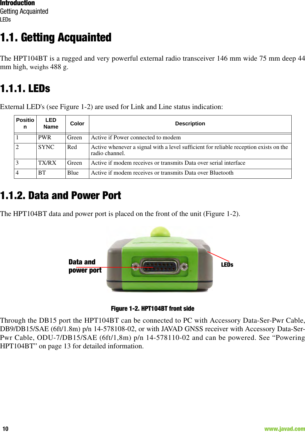
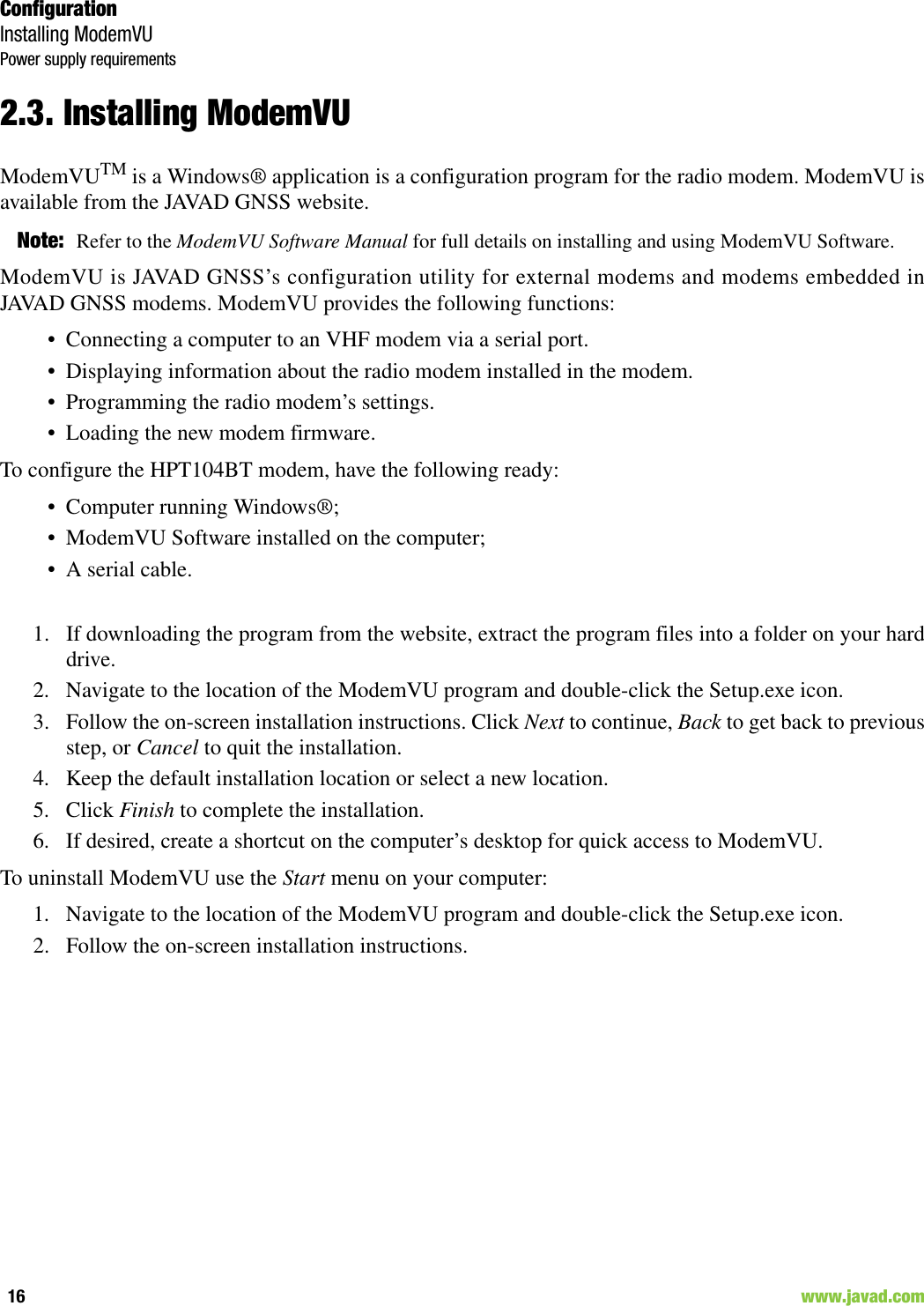
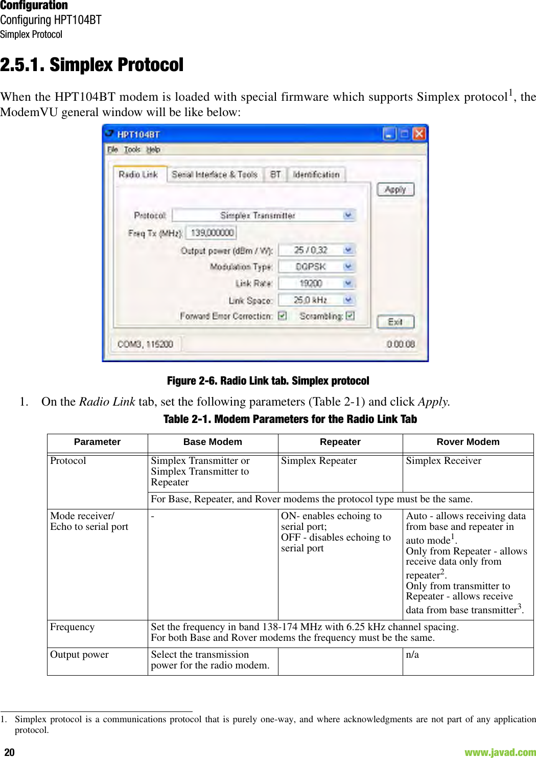
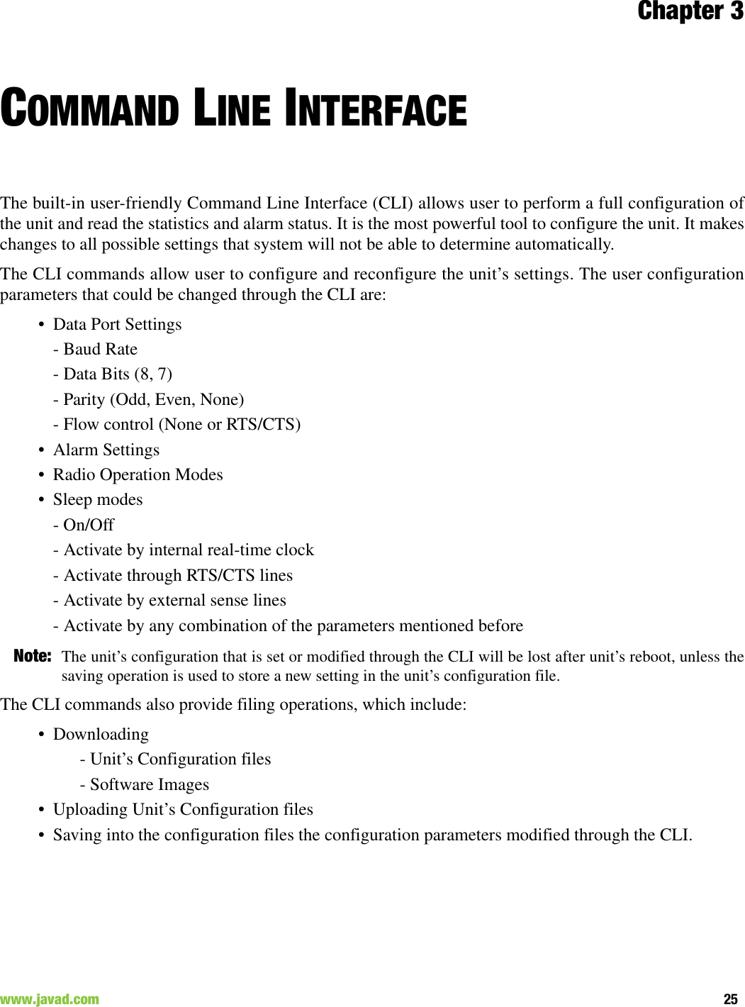
![Command Line InterfaceSerial Interfacing CommandsDPORT30 www.javad.com3.3. Serial Interfacing Commands3.3.1. DPORTThe DPORT is an object that responsible for data port interface configurations like Bit Rate, FlowControl, etc.DPORT [Parameter Name] [Parameters List] [/?]The response of command without Parameter Name indicates all values:RATE =0BITS =8PARITY =NONEFLOW =NONEDTR =0RS =RS232DATATX =UARTDATARX =UART, BTParameter Name Parameter ListRATE 0 – Maintenance Port baud rate, a default setting1 – 1200 baud2 – 2400 baud3 – 4800 baud4 – 9600 baud5 – 14400 baud6 – 19200 baud7 – 38400 baud8 – 57600 baud9 – 115200 baud, a default settingBITS Set number of bits in one byte (8 or 7) 8 is a default settingPARITY 0 – None, a default setting1 – Odd2 – EvenFLOW 0 – None, a default setting1 – Not used2 – HW (RTS/CTS)RS 0 - RS232, a default setting1 - RS4852 - RS422use save, boot commands to activate modificationDATATX 0 - UART, a default setting1 - USB2 - BTDATARX 0 - UART, a default setting1 - USB2 - BT](https://usermanual.wiki/JAVAD-GNSS/HPT104/User-Guide-1573423-Page-30.png)
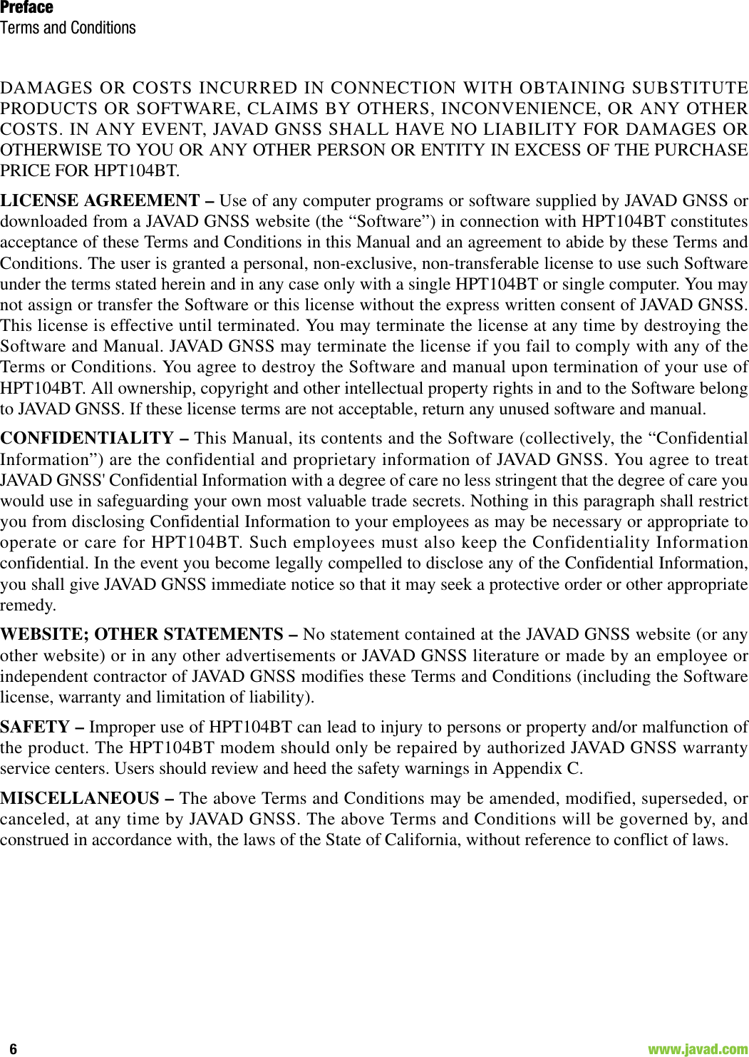
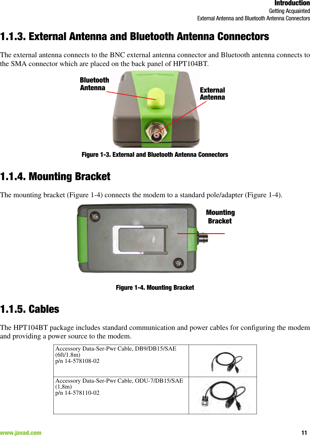
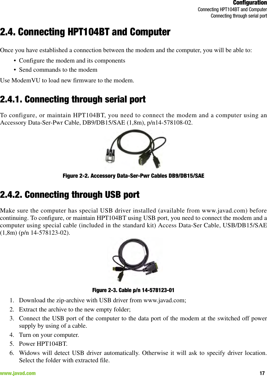
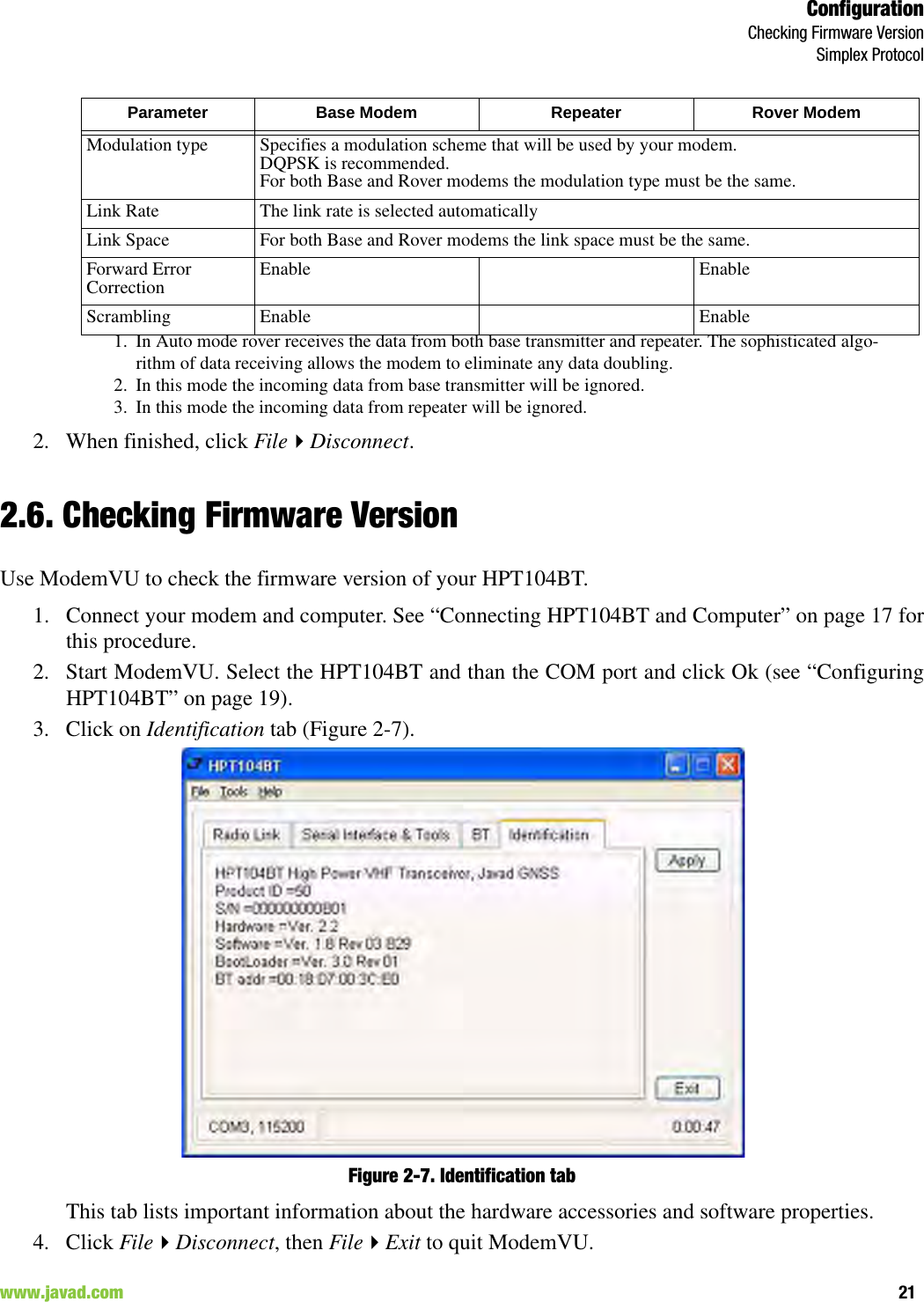
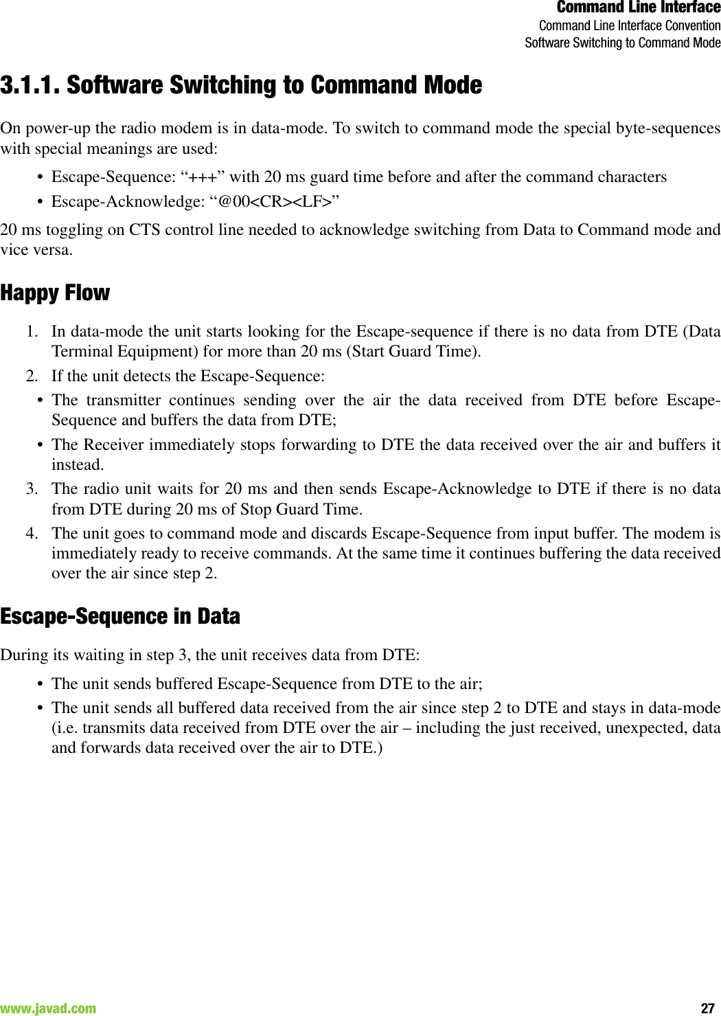
![Command Line InterfaceSpecial CommandsMPORT31www.javad.com 3.3.2. MPORTThe MPORT is an object that responsible for maintenance serial port interface configurations such as datarate and number of bits in a byte.MPORT [Parameter Name] [Parameters List] [/?]Note: JAVAD GNSS radio modem’s does not support data flow and parity on the maintenance serial port.Theradio modem with none-dedicated maintenance serial port must keep CTS line always active in MPORTmode (DP/MP is low).3.4. Special Commands3.4.1. BOOTThe factory software image and default configuration is set for the new unit. The BOOT command isintended to reboot the unit using specified software image and selected configuration. BOOT IMAGEBOOT CFGThe BOOT command with no parameters selects the user settings defined by the prior “parameterized”BOOT commands.3.4.2. HELPThe HELP command types the list of all available commands:HELP- Display this usageBOOT- Reboot the unitLINK- Set RF Link Operation ModeDPORT- Set Data Port ConfigurationMPORT- Set Maintenance Port ConfigurationALARM- Alarm Indication and Alarm Control ConfigurationParameter Name Parameter ListRATE 0 – Auto.1 – 1200 baud2 – 2400 baud3 – 4800 baud4 – 9600 baud5 – 14400 baud6 – 19200 baud7 – 38400 baud8 – 57600 baud9 – 115200 baud, a default setting](https://usermanual.wiki/JAVAD-GNSS/HPT104/User-Guide-1573423-Page-31.png)
![Command Line InterfaceSpecial CommandsSAVE32 www.javad.comSLEEP- Set Sleep Mode ConfigurationSTATE- Display Status and StatisticsSAVE- Save Current Configuration into Configuration FileINFO- Display Product ID along with Hardware/Software VersionsATI- Display Product ID along with Hardware/Software VersionsMAP- Operates with Channel MapDATAMODE- Exit Command Mode[COMMAND] /?- Display Command Usage3.4.3. SAVEThe SAVE command is intended to store the unit’s currently used configuration into the UserConfiguration file. The configuration stored in the User Configuration file is activated by automaticallyafter unit’s reboot.3.4.4. SLEEPThe SLEEP command determines the sleep mode parameters. The sleeping AW435BT can be activatedby real-time CLK, DTR/RTS lines, and command received through TTL inputs. The user can select one,two, or all three conditions.SLEEP [Parameter Name] [Parameters List] [/?] Parameter Name Parameter ListCLK 0 – Do not activate by internal real-time clock(1 – 255) – Activate by internal real-time clock after 100 to 25500 msec of sleepingHW 0 – Do not activate through DTR/RTS lines1 – Activate through DTR/RTS linesTTL 0 – Do not activate by external sense lines1 – Activate by external sense linesGTS 0 – Disable Sleep mode (default)(1 – 255) – Go to sleep mode if there is no activity in 10 to 2550 msec](https://usermanual.wiki/JAVAD-GNSS/HPT104/User-Guide-1573423-Page-32.png)
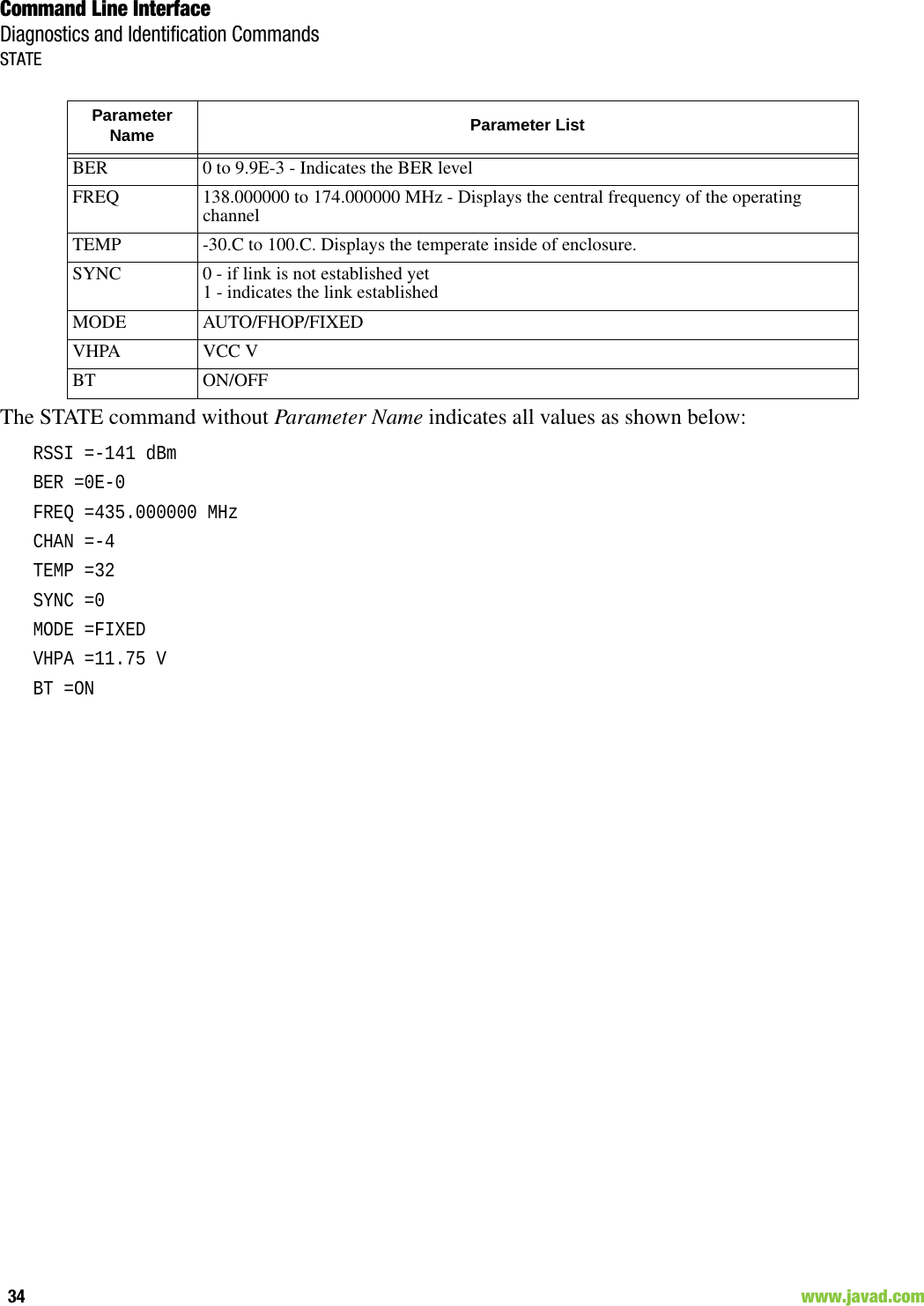
![Command Line InterfaceDiagnostics and Identification CommandsINFO33www.javad.com 3.5. Diagnostics and Identification Commands3.5.1. INFOThe INFO command is used to retrieve the Radio ID along with its Hardware version, the loaded real-time software version/revision and BootLoader’s version/revision.INFO [Parameter Name] [Parameters List] [/?]The INFO command without Parameter Name indicates all values:HPT104BT VHF Transceiver, Javad GNSSProduct ID =50S/N =0000000123BBHardware =Ver. 3.3Software =Ver. 1.8 Rev 04 B24BootLoader =Ver. 3.0 Rev 03BT addr =00:18:D7:00:3C:C73.5.2. STATEThe STATE command is used to check the state of the wireless link, the unit in the link, and the alarmcontrol lines. To specify a radio unit (local or remote), the CONNECT command must be used in prior ofSTATE command using.STATE [Parameter Name] [Parameters List] [/?]Parameter Name Parameter ListID Product ID:ID50 - HPT104BTID57 - AW100BTSN Six bytes Serial Number (SN)HW 1.0 - hardware version in numeric “Major.Minor” formatSW Ver. 1.0 Rev. A - displays software's version in numeric “Major.Minor” format and revision in numeric format (range from 01 to 99) for engineering releases and alphabetic format (A to Z) for manufacturing releasesBL Ver. 1.0 Rev. A - displays BootLoader’s version in numeric “Major.Minor” format and revision in numeric format (range from 01 to 99) for engineering releases and alphabetic format (A to Z) for manufacturing releasesBT Bluetooth serial numberParameter Name Parameter ListRSSI -15 to -137 dBm - Indicates the Receive Signal Strength in dBm](https://usermanual.wiki/JAVAD-GNSS/HPT104/User-Guide-1573423-Page-33.png)