JAVAD GNSS LMR400 UHF Radio module User Manual
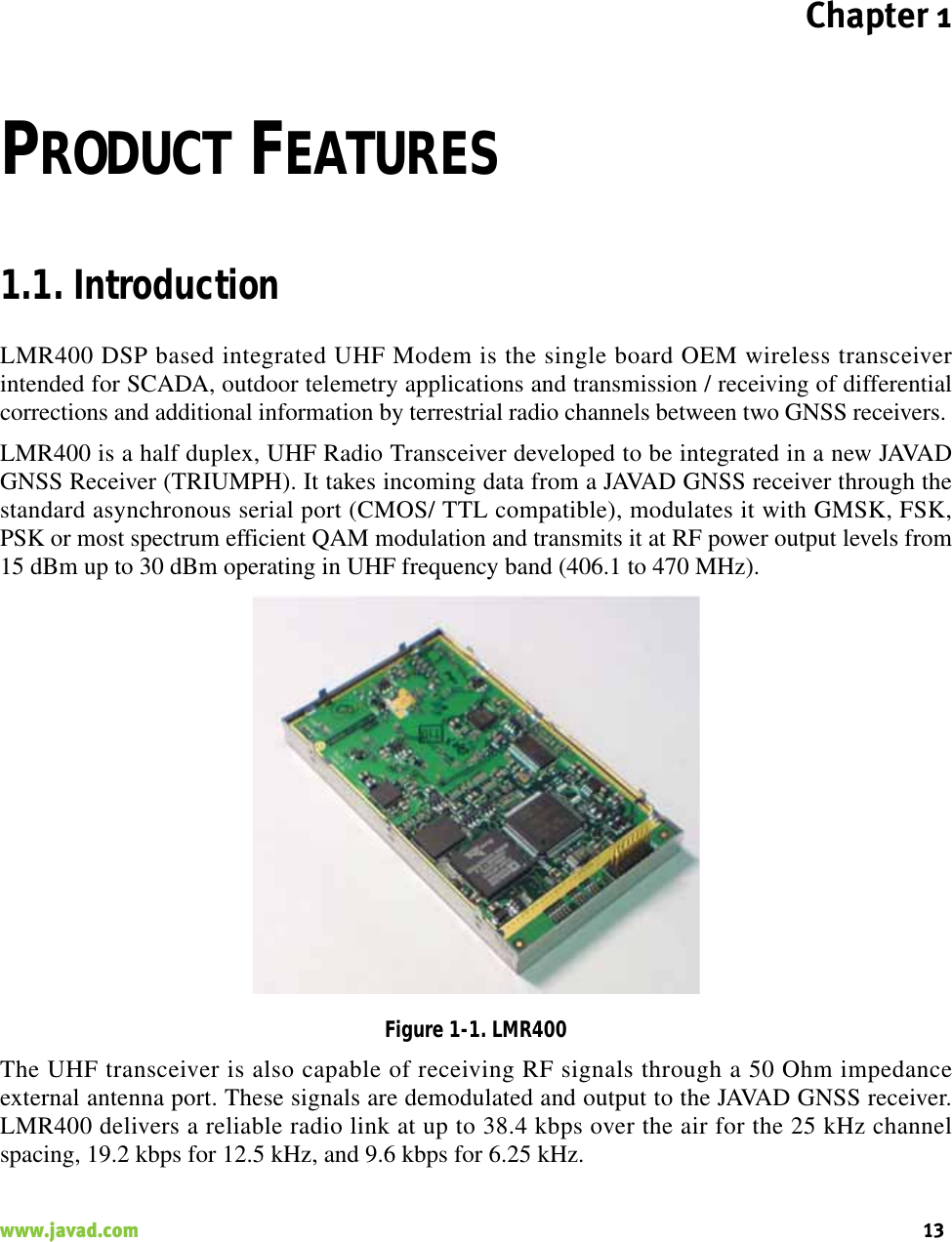
JAVAD GNSS, Inc. UHF Radio module
UserManual.wiki
>
JAVAD GNSS
>
LMR400 User Manual
User manual
Navigation menu
Upload a User Manual
Namespaces
Wiki Guide
HTML
PDF
Info
Views
User Manual
Discussion / Help
Navigation


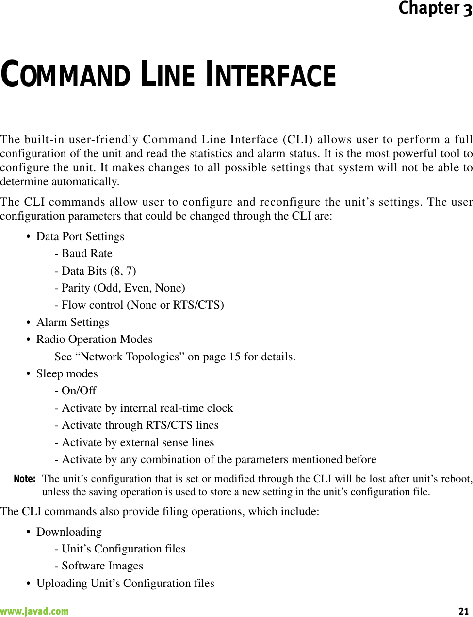
![Command Line InterfaceCommand Line Interface ConventionSoftware Switching to Maintenance Mode22 www.javad.com• Saving into the configuration files the configuration parameters modified through the CLI.3.1. Command Line Interface ConventionThe following convention is implemented in AW400Tx Command Line Interface (CLI):• The Carriage Return/Line Feed (CR/LF, 0x0D/0x0A) is a command delimiter.• The Carriage Return/Line Feed (CR/LF, 0x0D/0x0A) is a reply delimiter followed by the“CLI>” prompt if Echo option is On.• The Carriage Return/Line Feed (CR/LF, 0x0D/0x0A) is a reply delimiter if Echo option isOff (default option).• The 2-digit number followed by “@” in the unit’s reply indicates the error code (refer toTable 1 for description), if Echo Off is selected, otherwise the error message is displayed.• A successfully performed command is replied by @00 code, if Echo Off is selected,otherwise the set value is replied.• A command with the certain [Parameter Name] and blank [Parameter List] displays thecurrent settings for a given parameter.• To set the mode ordered by CLI commands as permanent User Setting (the settingautomatically selected for the boot-up unit) the SAVE command must be asserted.Table 1. Command Line Interface Error Codes3.1.1. Software Switching to Maintenance ModeSoftware Switching to Maintenance Mode can be utilized if Data/Maintenance Port (DP/MP)control line is set to High Z (or 3.3v) level. To switch to Maintenance mode the special byte-sequences with special meanings are used:Error Code Short Description0x01 Command Syntax Error. A command followed by “/?” displays a command usage.0x02 The parameter has a format error. A command with the certain [Parameter Name] followed by “/?” displays the format and range of the variable.0x03 The parameter is out of allowed range. A command with the certain [Parameter Name] followed by “/?” displays the format and range of the variable.0x04 The command is not valid for specific radio model. To display the list of available commands, the HELP command must be used (see “Software Switching to Maintenance Mode” ).0x05 Unspecified Error](https://usermanual.wiki/JAVAD-GNSS/LMR400/User-Guide-996321-Page-21.png)
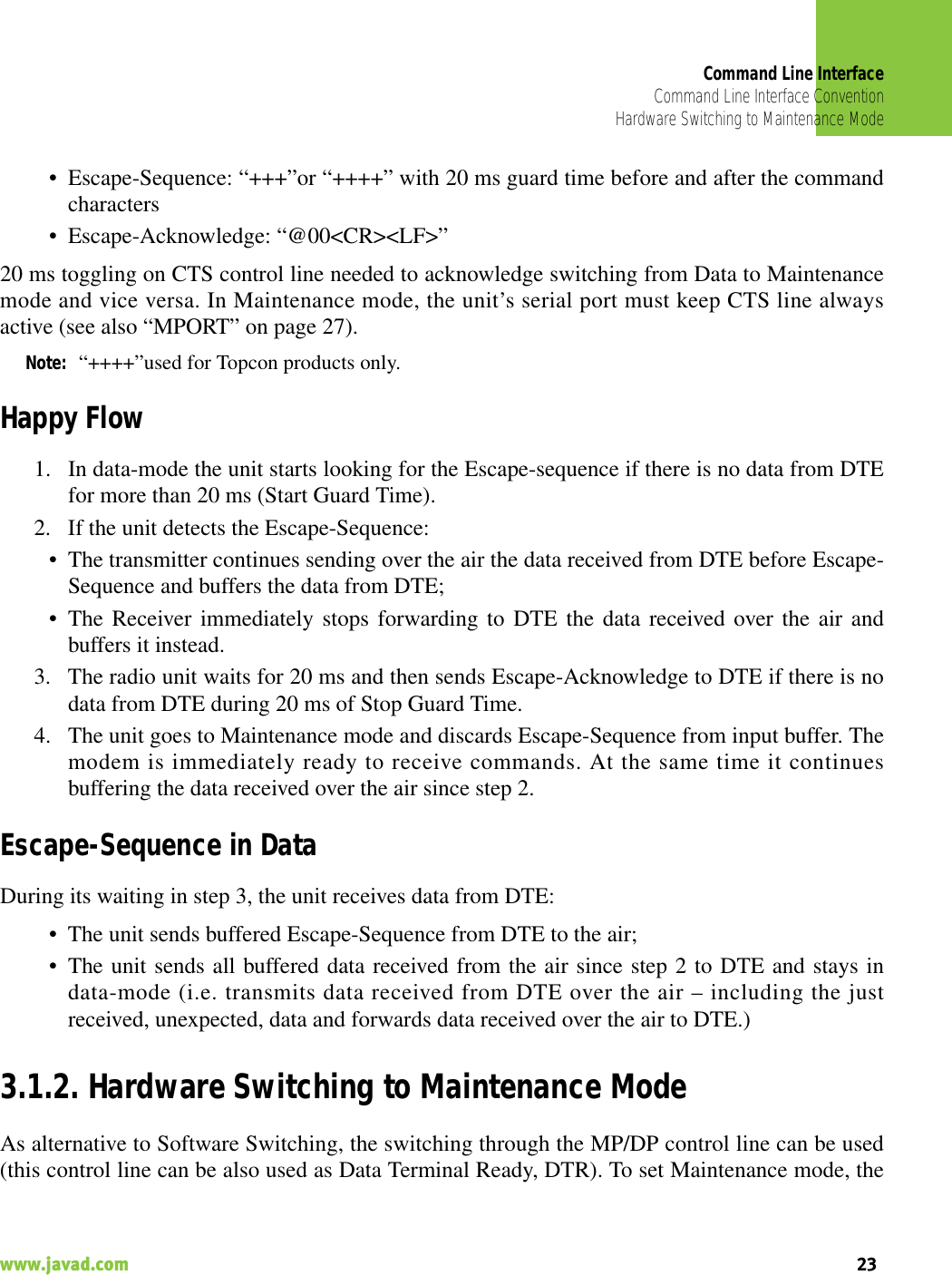
![Command Line InterfaceNetworking CommandsSwitching to Data Mode24 www.javad.comDTE must assert DTR signal active (0v level). By falling edge of DTR signal the unit goes toMaintenance mode and then sends Escape-Acknowledge to DTE („@00<CR><LF>“).20 ms toggling on CTS control line followed by Escape-Acknowledge response is needed toacknowledge switching from Data to Maintenance mode and vice versa. In Maintenance Mode,the unit’s serial port must keep Clear to Send (CTS) line always active (see also “MPORT” onpage 27).Note: The powered up radio modem by default goes to Data Mode regardless of DTR control linepolarity.3.1.3. Switching to Data Mode• DTE sends the CLI command „DATAMODE<CR><LF>“to the unit.• Unit answers with Escape-Acknowledge („@00<CR><LF>“) and immediately goes todatamode, so that the DTE can start sending data as soon as the Escape-Acknowledge hasbeen received.• If no valid CLI commands received from DTE within 1 minute, the unit will automaticallyswitch back to data-mode.Note: The data received over the air could be lost due to Rx buffer overflow if the unit stays inMaintenance mode longer then 15 second.3.2. Networking Commands3.2.1. CONNECTTo connect the radio unit through the local maintenance serial port or to establish the link with theremote unit in the Point-to-Multipoint network, the CONNECT command must be used.CONNECT [Unit_Numb] [/?]Where the Unit_Numb is an assigned decimal number for the unit to be connected. To get thecomplete unit list, the CONNECT command must be used with no parameter. The list of units inthe Point-to-Point link with the connection established with remote unit is shown in Figure 3-1:Figure 3-1. Connection ListUnit Serial Number ConnectBS 0035786599221 003574459923 C](https://usermanual.wiki/JAVAD-GNSS/LMR400/User-Guide-996321-Page-23.png)
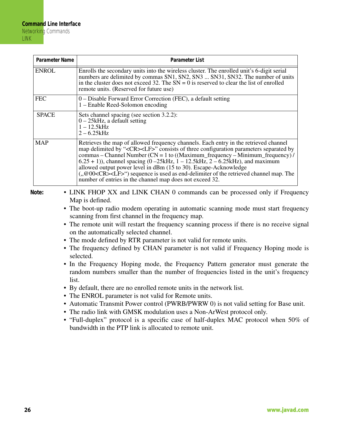
![Command Line InterfaceNetworking CommandsLINK25www.javad.com To connect to the Base unit, through the remote unit, the parameter (Unit_Numb) must be equal to0. To connect the local unit (Base or Remote), the parameter (Unit_Numb) must be equal to 0xFF.3.2.2. LINKThe LINK command is responsible for configuring radio’s operation mode. It has six parameterslisted below.LINK [Parameter Name] [Parameters List] [/?]Parameter Name Parameter ListPROT 1 – “Simplex Receiver”, a default setting for Remote units2 – “Simplex Transmitter”3 – “Half Duplex” specific for remote units (Reserved for future use)4 – “Half Duplex” specific for base unit (Reserved for future use)5 – “Full Duplex” specific for remote units (Reserved for future use)6 – “Full Duplex” specific for base unit (Reserved for future use)7 – “TRMB Receiver” (used with GMSK modulation, not supported)8 – “TRMB Transmitter” (used with GMSK modulation, not supported)9 – Reserved for future use10 – “Repeater” (ArWest Proprietary protocol)11 – “TRMB Repeater” (used with GMSK modulation, not supported)12 – “Transparent w/EOT” Receiver (used with GMSK modulation, not supported)13 – “Transparent w/EOT” Transmitter (used with GMSK modulation, not supported)RTR 0 – No Retransmission in the wireless cluster1 – There is RepeaterMOD 1 – DBPSK2 – DQPSK, a default settings3 – D8PSK4 – D16QAM5 – GMSK6 – 4FSKPWRB / PWRW 0 – Automatic Transmit Power control, a default setting for Remote units(15 – 30) / (30 – 1000) – RF output Power in dBm / mWCHAN Selects the frequency channel, CN = (1 – ((Maximum_frequency – Minimum_frequency) / 6.25 + 1)).The CN = 0 is reserved to set the Frequency Automatic scanning mode. The LINK CHAN 0 command also forces the radio modem to continue scanning starting from the channel currently selected by automatic scanning algorithm.In Automatic scanning mode, to check the frequency channel currently used or scanned, the STATE command must be used (see section 6.5.2).FHOP (1 – 32) – Frequency Hoping Pattern numberSCRAM 0 – No Scrambling (a default setting)(1 – 255) – Seed for Pseudo-Random Sequence Generator](https://usermanual.wiki/JAVAD-GNSS/LMR400/User-Guide-996321-Page-24.png)
![Command Line InterfaceSerial Interfacing CommandsDPORT27www.javad.com 3.3. Serial Interfacing Commands3.3.1. DPORTThe DPORT is an object that responsible for data port interface configurations like Bit Rate, FlowControl,etc.DPORT [Parameter Name] [Parameters List] [/?]3.3.2. MPORTThe MPORT is an object that responsible for maintenance serial port interface configurationssuch as data rate and number of bits in a byte.Parameter Name Parameter ListRATE 0 – Maintenance Port baud rate, a default setting1 – 1200 baud2 – 2400 baud3 – 4800 baud4 – 9600 baud5 – 14400 baud6 – 19200 baud7 – 38400 baud8 – 57600 baud9 – 115200 baud, a default settingBITS Set number of bits in one byte (8 or 7) 8 is a default settingPARITY 0 – None, a default setting1 – Odd2 – EvenFLOW 0 – None, a default setting1 – Not used2 – HW (RTS/CTS)3 – RS-485 TX Enable High4 – RS-485 TX Enable Low](https://usermanual.wiki/JAVAD-GNSS/LMR400/User-Guide-996321-Page-26.png)
![Command Line InterfaceSpecial CommandsALARM28 www.javad.comMPORT [Parameter Name] [Parameters List] [/?]Note: • MPORT operates using 8 bits in one byte fixed (not configurable).• The radio modem with none-dedicated maintenance serial port must keep CTS linealways active in MPORT mode (DP/MP is low).3.4. Special Commands3.4.1. ALARMThe ALARM command is intended to set up the alarm indication mode and alarm control lines’behavior.ALARM [Parameter Name] [Parameters List] [/?]Note: The BERTH 1 / 2 is optional for TTL2 = 3 condition, otherwise the BERT alarm is offParameter Name Parameter ListRATE 0 – Auto.1 – 1200 baud2 – 2400 baud3 – 4800 baud4 – 9600 baud5 – 14400 baud6 – 19200 baud7 – 38400 baud8 – 57600 baud9 – 115200 baud, a default settingParameter Name Parameter ListTTL1 0 – TTL_OUT1 = logic “1”1 – TTL_OUT1 = TTL_IN, received from remote unit (default settings)TTL2 0 – TTL_OUT2 = logic “1”1 – TTL_OUT2 = TTL_IN2, received from remote unit (default settings)2 – TTL_OUT2 = SYNC Loss3 – TTL_OUT2 = BER > BERTH or SYNC LossBERTH 1– BER Threshold >10 –3 (default threshold level for BER)2 – BER Threshold BER >10 –2](https://usermanual.wiki/JAVAD-GNSS/LMR400/User-Guide-996321-Page-27.png)
![Command Line InterfaceSpecial CommandsBOOT29www.javad.com 3.4.2. BOOTThe BOOT command is intended to reboot the unit using selected user settings. Two options areavailable, to use the default user settings defined by dealer or to use the settings defined by end-user BOOT [Parameter Name] [Parameters List] [/?] The BOOT command with no parameters selects the user settings defined by the prior“parameterized” BOOT commands.3.4.3. HELPThe HELP command types the list of all available commands:HELP – Display this usageBOOT – Reboot the unitLINK – RF Link Operation ModeDPORT – Data Port ConfigurationMPORT – Maintenance Port ConfigurationALARM – Alarm Indication and Alarm Control ConfigurationSLEEP – Sleep Mode ConfigurationCONNECT – Connect to Specified UnitSTATE – Display Status and StatisticsSAVE – Save Current Configuration into Configuration FileINFO – Display Product ID along with Hardware/Software VersionsDATAMODE – Exit Maintenance Mode[COMMAND] /? – Display Command Usage3.4.4. SAVEThe SAVE command is intended to store the unit’s currently used configuration into the UserConfiguration file. The configuration stored in the User Configuration file will be activated byautomatically after unit’s reboot.Parameter Name Parameter ListCFG 0 – selects the default user settings1 – selects user modified settings](https://usermanual.wiki/JAVAD-GNSS/LMR400/User-Guide-996321-Page-28.png)
![Command Line InterfaceDiagnostics and Identification CommandsSLEEP30 www.javad.com3.4.5. SLEEPThe SLEEP command determines the sleep mode parameters. The sleeping LMR400 can beactivated by real-time CLK, DTR/RTS lines, and command received through TTL inputs. Theuser can select one, two, or all three conditions.SLEEP [Parameter Name] [Parameters List] [/?] 3.5. Diagnostics and Identification Commands3.5.1. INFOThe INFO command is used to retrieve the Radio ID along with its Hardware version, the loadedrealtime software version/revision and BootLoader’s version/revision.INFO [Parameter Name] [Parameters List] [/?]The INFO command without Parameter Name indicates all values as shown in Figure 3-2:Parameter Name Parameter ListCLK 0 – Do not activate by internal real-time clock(1 – 255) – Activate by internal real-time clock after 100 to 25500 msec of sleepingHW 0 – Do not activate through DTR/RTS lines1 – Activate through DTR/RTS linesTTL 0 – Do not activate by external sense lines1 – Activate by external sense linesGTS 0 – Disable Sleep mode (default)(1 – 255) – Go to sleep mode if there is no activity in 10 to 2550 msecParameter Name Parameter ListID Product IDSN Six bytes Serial Number (SN)HW 1.0 – hardware version in numeric “Major.Minor” formatSW Ver. 1.0 Rev. A – displays software’s version in numeric “Major.Minor” format and revision in numeric format (range from 01 to 99) for engineering releases and alphabetic format (A to Z) for manufacturing releasesBL Ver. 1.0 Rev. A – displays BootLoader’s version in numeric “Major.Minor”format and revision in numeric format (range from 01 to 99) for engineering releases and alphabetic format (A to Z) for manufacturing releases](https://usermanual.wiki/JAVAD-GNSS/LMR400/User-Guide-996321-Page-29.png)
![Command Line InterfaceDiagnostics and Identification CommandsSTATE31www.javad.com Product ID = 6S/N = 000000 020303Hardware = Ver. 1.0Software = Ver. 1.0 Rev. BBootLoader = Ver. 1.0 Rev. A Figure 3-2. INFO Command Display3.5.2. STATEThe STATE command is used to check the state of the wireless link, the unit in the link, and thealarm control lines. To specify a radio unit (local or remote), the CONNECT command must beused in prior of STATE command using.STATE [Parameter Name] [Parameters List] [/?]Note: The indicated receive signal strength (RSSI) is equal to -147 dBm if there is no signal receivedfrom transmitter.Parameter Name Parameter ListTTL1 0/1 – State of TTL_IN1 lineTTL2 0/1 – State of TTL_IN2 lineRSSI -52 to -116 dBm – Indicates the Receive Signal Strength in dBmBER 1.0E-6 to 9.9E-3 – Indicates the BER levelFREQ 403.000000 to 470.000000 MHz – Displays the central frequency of the operating channelCHAN 1 to 9601 – Displays the selected or currently scanned frequency channelTEMP -30°C to 100°C – Displays the temperature inside of enclosureSYNC 1 – Indicates the established link, 0 – if link is not established yetPWRB Indicates unit’s output power level in dBm (see “CONNECT” on page 24)](https://usermanual.wiki/JAVAD-GNSS/LMR400/User-Guide-996321-Page-30.png)