JAVAD GNSS LMR400 UHF Radio module User Manual
JAVAD GNSS, Inc. UHF Radio module
User manual

All contents in this manual are copyrighted by JAVAD GNSS.
All rights reserved.The information contained herein may not be used, accessed, copied,
stored, displayed, sold, modified, published, or distributed, or otherwise reproduced without express
written consent from JAVAD GNSS.
LMR400*
User manual
Version 1.0
Last Revised September 4, 2008
*Other names for marketing purposes are AW400Tx, AW400Jv
www.javad.com
3www.javad.com
TABLE OF CONTENTS
Preface . . . . . . . . . . . . . . . . . . . . . . . . . . . . . . . . . . . . . . . . . . . . . . . . . . . . . . . . . . . . . .5
Terms and Conditions. . . . . . . . . . . . . . . . . . . . . . . . . . . . . . . . . . . . . . . . . . . . . . . . . . . . . . . .5
Regulatory Information . . . . . . . . . . . . . . . . . . . . . . . . . . . . . . . . . . . . . . . . . . . . . . . . . . . . . .7
FCC Class A Compliance . . . . . . . . . . . . . . . . . . . . . . . . . . . . . . . . . . . . . . . . . . . . . . . . .7
Canadian Emissions Labeling Requirements . . . . . . . . . . . . . . . . . . . . . . . . . . . . . . . . . .7
Radio Apparatus Certificate . . . . . . . . . . . . . . . . . . . . . . . . . . . . . . . . . . . . . . . . . . . . . . .8
Glossary . . . . . . . . . . . . . . . . . . . . . . . . . . . . . . . . . . . . . . . . . . . . . . . . . . . . . . . . . . . . . . . . . .9
Related Information . . . . . . . . . . . . . . . . . . . . . . . . . . . . . . . . . . . . . . . . . . . . . . . . . . . . . . . .10
Technical Assistance . . . . . . . . . . . . . . . . . . . . . . . . . . . . . . . . . . . . . . . . . . . . . . . . . . .10
Reader Feedback . . . . . . . . . . . . . . . . . . . . . . . . . . . . . . . . . . . . . . . . . . . . . . . . . . . . . .11
Chapter 1. Product Features. . . . . . . . . . . . . . . . . . . . . . . . . . . . . . . . . . . . . . . . . . . . .13
1.1. Introduction . . . . . . . . . . . . . . . . . . . . . . . . . . . . . . . . . . . . . . . . . . . . . . . . . . . . . . . . . . .13
1.2. Operating at Ultra High Frequency Band . . . . . . . . . . . . . . . . . . . . . . . . . . . . . . . . . . . .14
1.3. Modulation Technique. . . . . . . . . . . . . . . . . . . . . . . . . . . . . . . . . . . . . . . . . . . . . . . . . . .15
1.4. Network Topologies . . . . . . . . . . . . . . . . . . . . . . . . . . . . . . . . . . . . . . . . . . . . . . . . . . . .15
1.5. Operating Modes . . . . . . . . . . . . . . . . . . . . . . . . . . . . . . . . . . . . . . . . . . . . . . . . . . . . . . .16
1.6. Management Tools . . . . . . . . . . . . . . . . . . . . . . . . . . . . . . . . . . . . . . . . . . . . . . . . . . . . .16
1.7. Security . . . . . . . . . . . . . . . . . . . . . . . . . . . . . . . . . . . . . . . . . . . . . . . . . . . . . . . . . . . . . .16
Chapter 2. General Description. . . . . . . . . . . . . . . . . . . . . . . . . . . . . . . . . . . . . . . . . . .19
2.1. Hardware Platform. . . . . . . . . . . . . . . . . . . . . . . . . . . . . . . . . . . . . . . . . . . . . . . . . . . . . .19
2.2. Physical Interfaces. . . . . . . . . . . . . . . . . . . . . . . . . . . . . . . . . . . . . . . . . . . . . . . . . . . . . .19
2.2.1. Serial Data/Command Interface . . . . . . . . . . . . . . . . . . . . . . . . . . . . . . . . . . . . . .19
2.2.2. RF Interface. . . . . . . . . . . . . . . . . . . . . . . . . . . . . . . . . . . . . . . . . . . . . . . . . . . . . .20
2.2.3. Antennas . . . . . . . . . . . . . . . . . . . . . . . . . . . . . . . . . . . . . . . . . . . . . . . . . . . . . . . .20
2.2.4. Power Interface . . . . . . . . . . . . . . . . . . . . . . . . . . . . . . . . . . . . . . . . . . . . . . . . . . .20
Chapter 3. Command Line Interface. . . . . . . . . . . . . . . . . . . . . . . . . . . . . . . . . . . . . . .21
3.1. Command Line Interface Convention . . . . . . . . . . . . . . . . . . . . . . . . . . . . . . . . . . . . . . .22

4 www.javad.com
3.1.1. Software Switching to Maintenance Mode . . . . . . . . . . . . . . . . . . . . . . . . . . . . . 22
3.1.2. Hardware Switching to Maintenance Mode. . . . . . . . . . . . . . . . . . . . . . . . . . . . . 23
3.1.3. Switching to Data Mode. . . . . . . . . . . . . . . . . . . . . . . . . . . . . . . . . . . . . . . . . . . . 24
3.2. Networking Commands . . . . . . . . . . . . . . . . . . . . . . . . . . . . . . . . . . . . . . . . . . . . . . . . . 24
3.2.1. CONNECT . . . . . . . . . . . . . . . . . . . . . . . . . . . . . . . . . . . . . . . . . . . . . . . . . . . . . . 24
3.2.2. LINK. . . . . . . . . . . . . . . . . . . . . . . . . . . . . . . . . . . . . . . . . . . . . . . . . . . . . . . . . . . 25
3.3. Serial Interfacing Commands . . . . . . . . . . . . . . . . . . . . . . . . . . . . . . . . . . . . . . . . . . . . . 27
3.3.1. DPORT. . . . . . . . . . . . . . . . . . . . . . . . . . . . . . . . . . . . . . . . . . . . . . . . . . . . . . . . . 27
3.3.2. MPORT . . . . . . . . . . . . . . . . . . . . . . . . . . . . . . . . . . . . . . . . . . . . . . . . . . . . . . . . 27
3.4. Special Commands . . . . . . . . . . . . . . . . . . . . . . . . . . . . . . . . . . . . . . . . . . . . . . . . . . . . . 28
3.4.1. ALARM . . . . . . . . . . . . . . . . . . . . . . . . . . . . . . . . . . . . . . . . . . . . . . . . . . . . . . . . 28
3.4.2. BOOT . . . . . . . . . . . . . . . . . . . . . . . . . . . . . . . . . . . . . . . . . . . . . . . . . . . . . . . . . . 29
3.4.3. HELP . . . . . . . . . . . . . . . . . . . . . . . . . . . . . . . . . . . . . . . . . . . . . . . . . . . . . . . . . . 29
3.4.4. SAVE . . . . . . . . . . . . . . . . . . . . . . . . . . . . . . . . . . . . . . . . . . . . . . . . . . . . . . . . . . 29
3.4.5. SLEEP . . . . . . . . . . . . . . . . . . . . . . . . . . . . . . . . . . . . . . . . . . . . . . . . . . . . . . . . . 30
3.5. Diagnostics and Identification Commands . . . . . . . . . . . . . . . . . . . . . . . . . . . . . . . . . . 30
3.5.1. INFO. . . . . . . . . . . . . . . . . . . . . . . . . . . . . . . . . . . . . . . . . . . . . . . . . . . . . . . . . . . 30
3.5.2. STATE . . . . . . . . . . . . . . . . . . . . . . . . . . . . . . . . . . . . . . . . . . . . . . . . . . . . . . . . . 31
Chapter 4. Technical Specifications. . . . . . . . . . . . . . . . . . . . . . . . . . . . . . . . . . . . . . . 33
4.1. Technical Specifications. . . . . . . . . . . . . . . . . . . . . . . . . . . . . . . . . . . . . . . . . . . . . . . . . 34
4.1.1. Radio Transceiver. . . . . . . . . . . . . . . . . . . . . . . . . . . . . . . . . . . . . . . . . . . . . . . . . 34
4.1.2. Radio Transmitter . . . . . . . . . . . . . . . . . . . . . . . . . . . . . . . . . . . . . . . . . . . . . . . . 34
4.1.3. Radio Receiver . . . . . . . . . . . . . . . . . . . . . . . . . . . . . . . . . . . . . . . . . . . . . . . . . . . 34
4.1.4. Modem . . . . . . . . . . . . . . . . . . . . . . . . . . . . . . . . . . . . . . . . . . . . . . . . . . . . . . . . . 35
4.1.5. General . . . . . . . . . . . . . . . . . . . . . . . . . . . . . . . . . . . . . . . . . . . . . . . . . . . . . . . . . 36
4.2. External Connectors . . . . . . . . . . . . . . . . . . . . . . . . . . . . . . . . . . . . . . . . . . . . . . . . . . . . 36
4.3. RF Connectors . . . . . . . . . . . . . . . . . . . . . . . . . . . . . . . . . . . . . . . . . . . . . . . . . . . . . . . . 37
Safety Warnings. . . . . . . . . . . . . . . . . . . . . . . . . . . . . . . . . . . . . . . . . . . . . . . . . . . . . . 39
General Warnings . . . . . . . . . . . . . . . . . . . . . . . . . . . . . . . . . . . . . . . . . . . . . . . . . . . . . . . . . 39
Usage Warnings. . . . . . . . . . . . . . . . . . . . . . . . . . . . . . . . . . . . . . . . . . . . . . . . . . . . . . . . . . . 39
UHF Radio Usage . . . . . . . . . . . . . . . . . . . . . . . . . . . . . . . . . . . . . . . . . . . . . . . . . . . . . 41
Warranty Terms . . . . . . . . . . . . . . . . . . . . . . . . . . . . . . . . . . . . . . . . . . . . . . . . . . . . . . 43

5www.javad.com
PREFACE
Thank you for purchasing this product. The materials available in this Manual (the “Manual”)
have been prepared by JAVAD GNSS, Inc. (“JAVAD GNSS”) for owners of JAVAD GNSS
products. It is designed to assist owners with the use of the LMR4001 and its use is subject to
these terms and conditions (the “Terms and Conditions”).
Note: Please read these Terms and Conditions carefully.
Terms and Conditions
USE – JAVAD GNSS receivers are designed to be used by a professional. The user is expected to
have a good knowledge and understanding of the user and safety instructions before operating,
inspecting or adjusting. Always wear the required protectors (safety shoes, helmet, etc.) when
operating the receiver.
COPYRIGHT – All information contained in this Manual is the intellectual property of, and
copyrighted material of JAVAD GNSS. All rights are reserved. You may not use, access, copy,
store, display, create derivative works of, sell, modify, publish, distribute, or allow any third party
access to, any graphics, content, information or data in this Manual without JAVAD GNSS’
express written consent and may only use such information for the care and operation of your
LMR400. The information and data in this Manual are a valuable asset of JAVAD GNSS and are
developed by the expenditure of considerable work, time and money, and are the result of original
selection, coordination and arrangement by JAVAD GNSS.
TRADEMARKS – LMR400, JAVAD GNSS® are trademarks or registered trademarks of JAVAD
GNSS. Windows® is a registered trademark of Microsoft Corporation. Product and company
names mentioned herein may be trademarks of their respective owners.
DISCLAIMER OF WARRANTY – EXCEPT FOR ANY WARRANTIES IN THIS MANUAL
OR A WARRANTY CARD ACCOMPANYING THE PRODUCT, THIS MANUAL AND THE
LMR400 ARE PROVIDED “AS-IS.” THERE ARE NO OTHER WARRANTIES. JAVAD GNSS
DISCLAIMS ANY IMPLIED WARRANTY OF MERCHANTABILITY OR FITNESS FOR
ANY PARTICULAR USE OR PURPOSE. JAVAD GNSS AND ITS DISTRIBUTORS SHALL
1. Other names for marketing purposes are AW400Tx, AW400Jv

Preface
Terms and Conditions
6 www.javad.com
NOT BE LIABLE FOR TECHNICAL OR EDITORIAL ERRORS OR OMISSIONS
CONTAINED HEREIN; NOR FOR INCIDENTAL OR CONSEQUENTIAL DAMAGES
RESULTING FROM THE FURNISHING, PERFORMANCE OR USE OF THIS MATERIAL
OR THE LMR400. SUCH DISCLAIMED DAMAGES INCLUDE BUT ARE NOT LIMITED
TO LOSS OF TIME, LOSS OR DESTRUCTION OF DATA, LOSS OF PROFIT, SAVINGS OR
REVENUE, OR LOSS OF THE PRODUCT'S USE. IN ADDITION, JAVAD GNSS IS NOT
RESPONSIBLE OR LIABLE FOR DAMAGES OR COSTS INCURRED IN CONNECTION
WITH OBTAINING SUBSTITUTE PRODUCTS OR SOFTWARE, CLAIMS BY OTHERS,
INCONVENIENCE, OR ANY OTHER COSTS. IN ANY EVENT, JAVAD GNSS SHALL
HAVE NO LIABILITY FOR DAMAGES OR OTHERWISE TO YOU OR ANY OTHER
PERSON OR ENTITY IN EXCESS OF THE PURCHASE PRICE FOR THE LMR400.
LICENSE AGREEMENT – Use of any computer programs or software supplied by JAVAD
GNSS or downloaded from a JAVAD GNSS website (the “Software”) in connection with the
LMR400 constitutes acceptance of these Terms and Conditions in this Manual and an agreement
to abide by these Terms and Conditions. The user is granted a personal, non-exclusive, non-
transferable license to use such Software under the terms stated herein and in any case only with a
single LMR400 or single computer. You may not assign or transfer the Software or this license
without the express written consent of JAVAD GNSS. This license is effective until terminated.
You may terminate the license at any time by destroying the Software and Manual. JAVAD GNSS
may terminate the license if you fail to comply with any of the Terms or Conditions. You agree to
destroy the Software and manual upon termination of your use of the LMR400. All ownership,
copyright and other intellectual property rights in and to the Software belong to JAVAD GNSS. If
these license terms are not acceptable, return any unused software and manual.
CONFIDENTIALITY – This Manual, its contents and the Software (collectively, the
“Confidential Information”) are the confidential and proprietary information of JAVAD GNSS.
You agree to treat JAVAD GNSS' Confidential Information with a degree of care no less stringent
that the degree of care you would use in safeguarding your own most valuable trade secrets.
Nothing in this paragraph shall restrict you from disclosing Confidential Information to your
employees as may be necessary or appropriate to operate or care for the LMR400. Such
employees must also keep the Confidentiality Information confidential. In the event you become
legally compelled to disclose any of the Confidential Information, you shall give JAVAD GNSS
immediate notice so that it may seek a protective order or other appropriate remedy.
WEBSITE; OTHER STATEMENTS – No statement contained at the JAVAD GNSS website (or
any other website) or in any other advertisements or JAVAD GNSS literature or made by an
employee or independent contractor of JAVAD GNSS modifies these Terms and Conditions
(including the Software license, warranty and limitation of liability).
SAFETY – Improper use of the LMR400 can lead to injury to persons or property and/or
malfunction of the product. The LMR400 should only be repaired by authorized JAVAD GNSS

Preface
Regulatory Information
FCC Class A Compliance
7www.javad.com
warranty service centers. Users should review and heed the safety warnings in Chapter 5 on page
39.
MISCELLANEOUS – The above Terms and Conditions may be amended, modified,
superseded, or canceled, at any time by JAVAD GNSS. The above Terms and Conditions will be
governed by, and construed in accordance with, the laws of the State of California, without
reference to conflict of laws.
Regulatory Information
The following sections provide information on this product's compliance with government
regulations.
FCC Class A Compliance
This equipment has been tested and found to comply with the limits for a Class A digital device,
pursuant to part 15 of the FCC Rules. These limits are designed to provide reasonable protection
against harmful interference when the equipment is operated in a commercial environment. This
equipment generates, uses, and can radiate radio frequency energy and, if not installed and used
in accordance with the instruction manual, may cause harmful interference to radio
communications. Operation of this equipment in a residential area is likely to cause harmful
interference in which case the user will be required to correct the interference at his own expense.
Note: Any changes or modifications to the equipment not expressly approved by the party responsible
for compliance could void your authority to operate such equipment.
Canadian Emissions Labeling Requirements
This Class A digital apparatus meets all requirements of the Canadian Interference-Causing
Equipment Regulations.
Cet appareil numérique de la classe A respecte toutes les exigences du Réglement sur le matériel
brouilleur du Canada.

Preface
Glossary
Radio Apparatus Certificate
9www.javad.com
Glossary
μC Micro Controller
AGC Automatic Gain Control
ALC Automatic Output Power Level Control
AWGN Additive White Gaussian Noise
BER Bit Error Rate
BERT Bit Error Rate Test
CLI Command Line Interface
CMOS Complementary Metal-Oxide Semiconductor
CRC Cyclic Redundancy Code
CTS Clear To Send
CW Continues Wave
DBPSK Differential Binary Phase Shift Keying
DC Direct Current
DCD Data Carrier Detect
DQPSK Differential Quadrature Phase Shift Keying
DSP Digital Signal Processing
DSR Data Set Ready
DTE Data Terminal Equipment
DTR Data Terminal Ready
ETSI European Telecommunications Standardization Institute
FCC Federal Communications Commission
FEC Forward Error Correction
FIFO First-Input-First-Output
FSK Frequency Shift Keying
GMSK Minimum Shift Keying with Gaussian filtering
GUI Graphical User Interface
HPA High Power Amplifier
I/O Input/Output
IF Intermediate Frequency
LED Light Emitting Diode
LLC Logic Link Control
LNA Low Noise Amplifier
MAC Media Access Control
MSK Minimum-shift keying
MTBF Mean Time Between Failures
MTTR Mean Time To Repair
PA Power Amplifier
PCB Printed Circuit Board

Preface
Related Information
Technical Assistance
10 www.javad.com
PDA Personal Digital Assistant
PLL Phase-Lock Loop
PMP Point-to-Multipoint
PSK Phase Shift Keying
PTP Point-to-Point
QAM Quadrature Amplitude Modulation
QPSK Quadrature Phase Shift Keying
RF Radio Frequency
RSSI Received Signal Strength Indication
RTK Real-time Kinematics
RTS Request To Send
RX Receive(r)
SCADA Supervisor Control and Data Acquisition
SRAM Static Random Access Memory
TDD Time Division Duplex
TDM Time Division Multiplexing
TDMA Time Division Multiple Access
TPC Turbo Product Codes
TPO Transmitter Output Power
TTL Transistor-Transistor-Logic
TX Transmit(ter)
UART Universal Asynchronous Receiver/Transmitter
UHF Ultra High Frequency (300-3000 MHz)
UIM User Identify Module
VSWR Voltage Standing Wave Ratio
FIRMWARE A software program or a set of instructions embedded on a
hardware device
SOFTWARE Computer program for communication with a hardware device
Related Information
Technical Assistance
If you have a problem and cannot find the information you need in the product documentation,
contact your local dealer. Alternatively, request technical support using the JAVAD GNSS World
Wide Web site at: www.javad.com

Preface
Related Information
Reader Feedback
11www.javad.com
Reader Feedback
Your feedback about the supporting documentation helps us to improve the documentation with
each revision.
To forward your comments, do one of the following:
• Send an email to support@javad.com.
• Complete the Reader Comment Form at the back of this manual and mail or fax it
according to the instructions at the bottom of the form. Please mark it Attention:
Documentation Group.
All comments and suggestions become the property of JAVAD GNSS.

Preface
Related Information
Reader Feedback
12 www.javad.com
Chapter 1
13www.javad.com
PRODUCT FEATURES
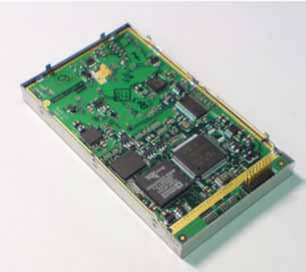
1.1. Introduction
LMR400 DSP based integrated UHF Modem is the single board OEM wireless transceiver
intended for SCADA, outdoor telemetry applications and transmission / receiving of differential
corrections and additional information by terrestrial radio channels between two GNSS receivers.
LMR400 is a half duplex, UHF Radio Transceiver developed to be integrated in a new JAVAD
GNSS Receiver (TRIUMPH). It takes incoming data from a JAVAD GNSS receiver through the
standard asynchronous serial port (CMOS/ TTL compatible), modulates it with GMSK, FSK,
PSK or most spectrum efficient QAM modulation and transmits it at RF power output levels from
15 dBm up to 30 dBm operating in UHF frequency band (406.1 to 470 MHz).
Figure 1-1. LMR400
The UHF transceiver is also capable of receiving RF signals through a 50 Ohm impedance
external antenna port. These signals are demodulated and output to the JAVAD GNSS receiver.
LMR400 delivers a reliable radio link at up to 38.4 kbps over the air for the 25 kHz channel
spacing, 19.2 kbps for 12.5 kHz, and 9.6 kbps for 6.25 kHz.
www.javad.com
The module requires a regulated DC voltage power supply 4.2 V ± 5 %.
The delivered product is a wireless system, which includes:
• LMR400 – UHF Radio Transceiver;
• “JRadio” – Windows based Unit Configuration and Maintenance Software Application
running on a IBM PC compatible computer and connecting to the device over RS-232
interface.
The unit’s user settings can be changed through the built-in Command Line interface (CLI), or
through JRadio. The system built-in diagnostic features provide the information required to
monitor and maintain user’s communications link. The output transmit power, receive signal
strength (RSSI), antenna/feed line condition, and data decode performance will be transmitted
online without application interruption.
The product is designed for maximum performance and reliability even in the harshest
environments. Plug and play at its best, robust, withstanding the most adverse of conditions.
1.2. Operating at Ultra High Frequency Band
LMR400 operates in UHF frequency band covering both licensed and unlicensed frequencies.
The following are its key benefits:
1. Operating in UHF frequency band will provide a non-line of sight connection.
2. User selectable operation mode (licensed or unlicensed mode) is a feature, which makes
JAVAD GNSS’s radio modems suitable for both licensed and unlicensed markets.
3. Relatively low cost associated with installation equipment compared to the licensed
wireless bands, since no capital is required to purchase spectrum rights.
4. User-selectable channel spacing (25/12.5/6.25 kHz) is a feature, which makes LMR400
modems attractive for distributors and system integrators.

Product Features
Modulation Technique
15www.javad.com
1.3. Modulation Technique
The design will be based on high-level modulation techniques which include:
The following are its key benefits:
1. Provides an excellent spectral efficiency (up to 2.3 bps/Hz for D16QAM), it is better than
any product available on the market.
2. Forward Error Correction scheme (FEC) is based on Hamming Code known as a Perfect
Code. Although Hamming Code is not very powerful, it is easy to implement and does not
require much DSP resources.
3. More powerful Reed-Solomon FEC coding scheme improves the tolerance to interference
and ensures the highest link quality at distances range higher than 15 miles (24 km) and
roaming speeds of up to 60 mph (96 km/h).
1.4. Network Topologies
LMR400 is developed to support Point-to-Point link (PTP) using Time Division Duplex (TDD)
protocol and Point-to-Multipoint (PMP) network topology using Time Division Multiple Access
(TDMA) protocol.
The media access contention between wireless nodes in PMP network (Remotes) can be resolved
by an external controller (TRIUMPH GNSS Receiver) located on base station (Base). The
CONNECT command is intended to establish the link with a specific Remote.
The RTS and CTS data flow control lines (Request-To-Send and Clear-To-Send) can be used on
Remote side to support TDMA protocol implementation.
6.25 kHz 12.5 kHz 25 kHz
DBPSK – Differential Binary Phase Shift Keying 2.4 kbps 4.8 kbps 9.6 kbps
DQPSK – Differential Quadrature Phase Shift Keying 4.8 kbps 9.6 kbps 19.2 kbps
D8PSK – Eight Phase Shift Keying 7.2 kbps 14.4 kbps 28.8 kbps
D16QAM – Sixteen Quadrature Amplitude Modulation 9.6 kbps 19.2 kbps 38.4 kbps
GMSK – Minimal Shift Keying with Gaussian Filtering N\A*
*. N/A – Not Applicable
4.8 kbps 9.6 kbps

Product Features
Operating Modes
16 www.javad.com
1.5. Operating Modes
The operating modes for LMR400 can be set through the CLI, or through JRadio. The following
operating modes are available for LMR400:
1. Simplex operating modes (Simplex Base, Remote and Repeater) are developed primarily
for GNSS applications.
2. Half Duplex Base, Remote and Repeater are the alternative to Simplex operating modes
that are implemented based on half-duplex TDD protocol with dynamic bandwidth
allocation.
3. Sleep mode has automatic transmitter activation by an internal real-time clock, or by an
external controller through the data interface control lines (RTS).
4. The programmable automatic channel scanning of the Preferred Channels is an alternative
mode to the operation on the fixed Frequency Channel. In this mode, the Base is looking
for a “free of use” frequency channel while a Remote is looking for a Base to interact with.
5. Test mode supports the radio installation using Built-in test tools.
1.6. Management Tools
The built-in management tools along with JRadio running on PC compatible computer provide
the following benefits:
1. Easy user’s interface for system configuration and monitoring using well developed CLI
or intuitive GUI.
2. An ability to test the link using built-in test utilities without expensive external test
equipment such as spectrum analyzer and BER test analyzer.
3. An ability to monitor status, alarms and radio performance through the intuitive GUI.
4. LMR400 firmware upgrades and improvements can be downloaded to the units over serial
link locally or over-the-air remotely.
Note: Downloading over-the-air remotely is not requested by JAVAD GNSS for first release.
1.7. Security
The system will provide wireless media access protection as well as data encryption. The
following are its key features and benefits:

Product Features
Security
17www.javad.com
1. The Key Sequence generated by Pseudo-random generator scrambles the fully formatted
frame (including Frame’s CRC). This provides the wireless media access protection.
2. User selectable Frequency Hopping Pattern provides another level of the wireless media
access protection.
At the same time it allows operators to increase the number of links deployed in the same
location.

Product Features
Security
18 www.javad.com
Chapter 2
19www.javad.com
GENERAL DESCRIPTION
2.1. Hardware Platform
UHF module electronic hardware consists of Zero-IF RF Front-End and Digital Section based on
BlackFin DSP micro processor. Both are located on a single PCB board.
LMR400 radio modem utilizes ultra-wide dynamic range RF front-end developed specifically to
provide the adjacent channel power ratio and adjacent channel selectivity levels required by FCC
Part 90 standards.
Digital Section is responsible for:
• Baseband modulation/demodulation;
• MAC Protocol performance;
• Serial Data Interface Control Logic (RTS and CTS).
• System Initialization and configuration including initialization of configurable devices in
the RF frontend.
Both factory and user specific configuration parameters will be stored in the flash memory.
However, only user specific parameters can be changed on the field. The factory configuration
includes maximum allowed output power (500mW – unlicensed and 1 W – licensed), six-byte
unique serial number, and unit specific calibration tables.
2.2. Physical Interfaces
2.2.1. Serial Data/Command Interface
The serial asynchronous interface allows connection to external serial devices. It is shared
between user data and unit’s command/status information. All commonly supported baud rates,
parity and bit configurations are available up to 115.2 kbps for UART.
www.javad.com
2.2.2. RF Interface
RF interface is a 50-ohm impedance matched standard MMCX connector as required by
regulation. The RF interface can operate without damage to the unit under DC short and open
conditions.
The RF interface is protected against static discharge (15 kV air discharge, 8 kV contact
discharge) and unloaded output.
Switching from UHF module to cell module operation mode and vice versa is provided on RF
interface in case if they share the same antenna.
2.2.3. Antennas
Antenna type depends on the site requirements, and may be directional or omni-directional. The
antenna must have a 50-ohm impedance matched interface with VSWR 2.0:1 or better.
The Base transceiver is recommended to be mounted on an antenna mast that elevates the antenna
a minimum of 40 feet above the average level of the terrain to support 15 miles distance range.
2.2.4. Power Interface
The power interface allows connection to an unregulated DC power source. The DC power source
(thirdparty or user supplied) must provide peak 7.5 W of DC power 4.2 V ± 5 %.
Chapter 3
21www.javad.com
COMMAND LINE INTERFACE
The built-in user-friendly Command Line Interface (CLI) allows user to perform a full
configuration of the unit and read the statistics and alarm status. It is the most powerful tool to
configure the unit. It makes changes to all possible settings that system will not be able to
determine automatically.
The CLI commands allow user to configure and reconfigure the unit’s settings. The user
configuration parameters that could be changed through the CLI are:
• Data Port Settings
- Baud Rate
- Data Bits (8, 7)
- Parity (Odd, Even, None)
- Flow control (None or RTS/CTS)
• Alarm Settings
• Radio Operation Modes
See “Network Topologies” on page 15 for details.
• Sleep modes
- On/Off
- Activate by internal real-time clock
- Activate through RTS/CTS lines
- Activate by external sense lines
- Activate by any combination of the parameters mentioned before
Note: The unit’s configuration that is set or modified through the CLI will be lost after unit’s reboot,
unless the saving operation is used to store a new setting in the unit’s configuration file.
The CLI commands also provide filing operations, which include:
• Downloading
- Unit’s Configuration files
- Software Images
• Uploading Unit’s Configuration files

Command Line Interface
Command Line Interface Convention
Software Switching to Maintenance Mode
22 www.javad.com
• Saving into the configuration files the configuration parameters modified through the CLI.
3.1. Command Line Interface Convention
The following convention is implemented in AW400Tx Command Line Interface (CLI):
• The Carriage Return/Line Feed (CR/LF, 0x0D/0x0A) is a command delimiter.
• The Carriage Return/Line Feed (CR/LF, 0x0D/0x0A) is a reply delimiter followed by the
“CLI>” prompt if Echo option is On.
• The Carriage Return/Line Feed (CR/LF, 0x0D/0x0A) is a reply delimiter if Echo option is
Off (default option).
• The 2-digit number followed by “@” in the unit’s reply indicates the error code (refer to
Table 1 for description), if Echo Off is selected, otherwise the error message is displayed.
• A successfully performed command is replied by @00 code, if Echo Off is selected,
otherwise the set value is replied.
• A command with the certain [Parameter Name] and blank [Parameter List] displays the
current settings for a given parameter.
• To set the mode ordered by CLI commands as permanent User Setting (the setting
automatically selected for the boot-up unit) the SAVE command must be asserted.
Table 1. Command Line Interface Error Codes
3.1.1. Software Switching to Maintenance Mode
Software Switching to Maintenance Mode can be utilized if Data/Maintenance Port (DP/MP)
control line is set to High Z (or 3.3v) level. To switch to Maintenance mode the special byte-
sequences with special meanings are used:
Error Code Short Description
0x01 Command Syntax Error. A command followed by “/?” displays a command usage.
0x02 The parameter has a format error. A command with the certain [Parameter Name]
followed by “/?” displays the format and range of the variable.
0x03 The parameter is out of allowed range. A command with the certain [Parameter Name]
followed by “/?” displays the format and range of the variable.
0x04 The command is not valid for specific radio model. To display the list of available
commands, the HELP command must be used (see “Software Switching to Maintenance
Mode” ).
0x05 Unspecified Error

Command Line Interface
Command Line Interface Convention
Hardware Switching to Maintenance Mode
23www.javad.com
• Escape-Sequence: “+++”or “++++” with 20 ms guard time before and after the command
characters
• Escape-Acknowledge: “@00<CR><LF>”
20 ms toggling on CTS control line needed to acknowledge switching from Data to Maintenance
mode and vice versa. In Maintenance mode, the unit’s serial port must keep CTS line always
active (see also “MPORT” on page 27).
Note: “++++”used for Topcon products only.
Happy Flow
1. In data-mode the unit starts looking for the Escape-sequence if there is no data from DTE
for more than 20 ms (Start Guard Time).
2. If the unit detects the Escape-Sequence:
• The transmitter continues sending over the air the data received from DTE before Escape-
Sequence and buffers the data from DTE;
• The Receiver immediately stops forwarding to DTE the data received over the air and
buffers it instead.
3. The radio unit waits for 20 ms and then sends Escape-Acknowledge to DTE if there is no
data from DTE during 20 ms of Stop Guard Time.
4. The unit goes to Maintenance mode and discards Escape-Sequence from input buffer. The
modem is immediately ready to receive commands. At the same time it continues
buffering the data received over the air since step 2.
Escape-Sequence in Data
During its waiting in step 3, the unit receives data from DTE:
• The unit sends buffered Escape-Sequence from DTE to the air;
• The unit sends all buffered data received from the air since step 2 to DTE and stays in
data-mode (i.e. transmits data received from DTE over the air – including the just
received, unexpected, data and forwards data received over the air to DTE.)
3.1.2. Hardware Switching to Maintenance Mode
As alternative to Software Switching, the switching through the MP/DP control line can be used
(this control line can be also used as Data Terminal Ready, DTR). To set Maintenance mode, the

Command Line Interface
Networking Commands
Switching to Data Mode
24 www.javad.com
DTE must assert DTR signal active (0v level). By falling edge of DTR signal the unit goes to
Maintenance mode and then sends Escape-Acknowledge to DTE („@00<CR><LF>“).
20 ms toggling on CTS control line followed by Escape-Acknowledge response is needed to
acknowledge switching from Data to Maintenance mode and vice versa. In Maintenance Mode,
the unit’s serial port must keep Clear to Send (CTS) line always active (see also “MPORT” on
page 27).
Note: The powered up radio modem by default goes to Data Mode regardless of DTR control line
polarity.
3.1.3. Switching to Data Mode
• DTE sends the CLI command „DATAMODE<CR><LF>“to the unit.
• Unit answers with Escape-Acknowledge („@00<CR><LF>“) and immediately goes to
datamode, so that the DTE can start sending data as soon as the Escape-Acknowledge has
been received.
• If no valid CLI commands received from DTE within 1 minute, the unit will automatically
switch back to data-mode.
Note: The data received over the air could be lost due to Rx buffer overflow if the unit stays in
Maintenance mode longer then 15 second.
3.2. Networking Commands
3.2.1. CONNECT
To connect the radio unit through the local maintenance serial port or to establish the link with the
remote unit in the Point-to-Multipoint network, the CONNECT command must be used.
CONNECT [Unit_Numb] [/?]
Where the Unit_Numb is an assigned decimal number for the unit to be connected. To get the
complete unit list, the CONNECT command must be used with no parameter. The list of units in
the Point-to-Point link with the connection established with remote unit is shown in Figure 3-1:
Figure 3-1. Connection List
Unit Serial Number Connect
BS 003578659922
1 003574459923 C

Command Line Interface
Networking Commands
LINK
25www.javad.com
To connect to the Base unit, through the remote unit, the parameter (Unit_Numb) must be equal to
0. To connect the local unit (Base or Remote), the parameter (Unit_Numb) must be equal to 0xFF.
3.2.2. LINK
The LINK command is responsible for configuring radio’s operation mode. It has six parameters
listed below.
LINK [Parameter Name] [Parameters List] [/?]
Parameter Name Parameter List
PROT 1 – “Simplex Receiver”, a default setting for Remote units
2 – “Simplex Transmitter”
3 – “Half Duplex” specific for remote units (Reserved for future use)
4 – “Half Duplex” specific for base unit (Reserved for future use)
5 – “Full Duplex” specific for remote units (Reserved for future use)
6 – “Full Duplex” specific for base unit (Reserved for future use)
7 – “TRMB Receiver” (used with GMSK modulation, not supported)
8 – “TRMB Transmitter” (used with GMSK modulation, not supported)
9 – Reserved for future use
10 – “Repeater” (ArWest Proprietary protocol)
11 – “TRMB Repeater” (used with GMSK modulation, not supported)
12 – “Transparent w/EOT” Receiver (used with GMSK modulation, not supported)
13 – “Transparent w/EOT” Transmitter (used with GMSK modulation, not supported)
RTR 0 – No Retransmission in the wireless cluster
1 – There is Repeater
MOD 1 – DBPSK
2 – DQPSK, a default settings
3 – D8PSK
4 – D16QAM
5 – GMSK
6 – 4FSK
PWRB /
PWRW 0 – Automatic Transmit Power control, a default setting for Remote units
(15 – 30) / (30 – 1000) – RF output Power in dBm / mW
CHAN Selects the frequency channel, CN = (1 – ((Maximum_frequency –
Minimum_frequency) / 6.25 + 1)).
The CN = 0 is reserved to set the Frequency Automatic scanning mode. The LINK
CHAN 0 command also forces the radio modem to continue scanning starting from the
channel currently selected by automatic scanning algorithm.
In Automatic scanning mode, to check the frequency channel currently used or scanned,
the STATE command must be used (see section 6.5.2).
FHOP (1 – 32) – Frequency Hoping Pattern number
SCRAM 0 – No Scrambling (a default setting)
(1 – 255) – Seed for Pseudo-Random Sequence Generator

Command Line Interface
Networking Commands
LINK
26 www.javad.com
Note: • LINK FHOP XX and LINK CHAN 0 commands can be processed only if Frequency
Map is defined.
• The boot-up radio modem operating in automatic scanning mode must start frequency
scanning from first channel in the frequency map.
• The remote unit will restart the frequency scanning process if there is no receive signal
on the automatically selected channel.
• The mode defined by RTR parameter is not valid for remote units.
• The frequency defined by CHAN parameter is not valid if Frequency Hoping mode is
selected.
• In the Frequency Hoping mode, the Frequency Pattern generator must generate the
random numbers smaller than the number of frequencies listed in the unit’s frequency
list.
• By default, there are no enrolled remote units in the network list.
• The ENROL parameter is not valid for Remote units.
• Automatic Transmit Power control (PWRB/PWRW 0) is not valid setting for Base unit.
• The radio link with GMSK modulation uses a Non-ArWest protocol only.
• “Full-duplex” protocol is a specific case of half-duplex MAC protocol when 50% of
bandwidth in the PTP link is allocated to remote unit.
ENROL Enrolls the secondary units into the wireless cluster. The enrolled unit’s 6-digit serial
numbers are delimited by commas SN1, SN2, SN3 ... SN31, SN32. The number of units
in the cluster does not exceed 32. The SN = 0 is reserved to clear the list of enrolled
remote units. (Reserved for future use)
FEC 0 – Disable Forward Error Correction (FEC), a default setting
1 – Enable Reed-Solomon encoding
SPACE Sets channel spacing (see section 3.2.2):
0 – 25kHz, a default setting
1 – 12.5kHz
2 – 6.25kHz
MAP Retrieves the map of allowed frequency channels. Each entry in the retrieved channel
map delimited by “<CR><LF>” consists of three configuration parameters separated by
commas – Channel Number (CN = 1 to ((Maximum_frequency – Minimum_frequency) /
6.25 + 1)), channel spacing (0 –25kHz, 1 – 12.5kHz, 2 – 6.25kHz), and maximum
allowed output power level in dBm (15 to 30). Escape-Acknowledge
(„@00<CR><LF>“) sequence is used as end-delimiter of the retrieved channel map. The
number of entries in the channel map does not exceed 32.
Parameter Name Parameter List

Command Line Interface
Serial Interfacing Commands
DPORT
27www.javad.com
3.3. Serial Interfacing Commands
3.3.1. DPORT
The DPORT is an object that responsible for data port interface configurations like Bit Rate, Flow
Control,etc.
DPORT [Parameter Name] [Parameters List] [/?]
3.3.2. MPORT
The MPORT is an object that responsible for maintenance serial port interface configurations
such as data rate and number of bits in a byte.
Parameter Name Parameter List
RATE 0 – Maintenance Port baud rate, a default setting
1 – 1200 baud
2 – 2400 baud
3 – 4800 baud
4 – 9600 baud
5 – 14400 baud
6 – 19200 baud
7 – 38400 baud
8 – 57600 baud
9 – 115200 baud, a default setting
BITS Set number of bits in one byte (8 or 7)
8 is a default setting
PARITY 0 – None, a default setting
1 – Odd
2 – Even
FLOW 0 – None, a default setting
1 – Not used
2 – HW (RTS/CTS)
3 – RS-485 TX Enable High
4 – RS-485 TX Enable Low

Command Line Interface
Special Commands
ALARM
28 www.javad.com
MPORT [Parameter Name] [Parameters List] [/?]
Note: • MPORT operates using 8 bits in one byte fixed (not configurable).
• The radio modem with none-dedicated maintenance serial port must keep CTS line
always active in MPORT mode (DP/MP is low).
3.4. Special Commands
3.4.1. ALARM
The ALARM command is intended to set up the alarm indication mode and alarm control lines’
behavior.
ALARM [Parameter Name] [Parameters List] [/?]
Note: The BERTH 1 / 2 is optional for TTL2 = 3 condition, otherwise the BERT alarm is off
Parameter Name Parameter List
RATE 0 – Auto.
1 – 1200 baud
2 – 2400 baud
3 – 4800 baud
4 – 9600 baud
5 – 14400 baud
6 – 19200 baud
7 – 38400 baud
8 – 57600 baud
9 – 115200 baud, a default setting
Parameter Name Parameter List
TTL1 0 – TTL_OUT1 = logic “1”
1 – TTL_OUT1 = TTL_IN, received from remote unit (default settings)
TTL2 0 – TTL_OUT2 = logic “1”
1 – TTL_OUT2 = TTL_IN2, received from remote unit (default settings)
2 – TTL_OUT2 = SYNC Loss
3 – TTL_OUT2 = BER > BERTH or SYNC Loss
BERTH 1– BER Threshold >10 –3 (default threshold level for BER)
2 – BER Threshold BER >10 –2

Command Line Interface
Special Commands
BOOT
29www.javad.com
3.4.2. BOOT
The BOOT command is intended to reboot the unit using selected user settings. Two options are
available, to use the default user settings defined by dealer or to use the settings defined by end-
user
BOOT [Parameter Name] [Parameters List] [/?]
The BOOT command with no parameters selects the user settings defined by the prior
“parameterized” BOOT commands.
3.4.3. HELP
The HELP command types the list of all available commands:
HELP – Display this usage
BOOT – Reboot the unit
LINK – RF Link Operation Mode
DPORT – Data Port Configuration
MPORT – Maintenance Port Configuration
ALARM – Alarm Indication and Alarm Control Configuration
SLEEP – Sleep Mode Configuration
CONNECT – Connect to Specified Unit
STATE – Display Status and Statistics
SAVE – Save Current Configuration into Configuration File
INFO – Display Product ID along with Hardware/Software Versions
DATAMODE – Exit Maintenance Mode
[COMMAND] /? – Display Command Usage
3.4.4. SAVE
The SAVE command is intended to store the unit’s currently used configuration into the User
Configuration file. The configuration stored in the User Configuration file will be activated by
automatically after unit’s reboot.
Parameter Name Parameter List
CFG 0 – selects the default user settings
1 – selects user modified settings

Command Line Interface
Diagnostics and Identification Commands
SLEEP
30 www.javad.com
3.4.5. SLEEP
The SLEEP command determines the sleep mode parameters. The sleeping LMR400 can be
activated by real-time CLK, DTR/RTS lines, and command received through TTL inputs. The
user can select one, two, or all three conditions.
SLEEP [Parameter Name] [Parameters List] [/?]
3.5. Diagnostics and Identification Commands
3.5.1. INFO
The INFO command is used to retrieve the Radio ID along with its Hardware version, the loaded
realtime software version/revision and BootLoader’s version/revision.
INFO [Parameter Name] [Parameters List] [/?]
The INFO command without Parameter Name indicates all values as shown in Figure 3-2:
Parameter Name Parameter List
CLK 0 – Do not activate by internal real-time clock
(1 – 255) – Activate by internal real-time clock after 100 to 25500 msec of sleeping
HW 0 – Do not activate through DTR/RTS lines
1 – Activate through DTR/RTS lines
TTL 0 – Do not activate by external sense lines
1 – Activate by external sense lines
GTS 0 – Disable Sleep mode (default)
(1 – 255) – Go to sleep mode if there is no activity in 10 to 2550 msec
Parameter Name Parameter List
ID Product ID
SN Six bytes Serial Number (SN)
HW 1.0 – hardware version in numeric “Major.Minor” format
SW Ver. 1.0 Rev. A – displays software’s version in numeric “Major.Minor” format and
revision in numeric format (range from 01 to 99) for engineering releases and alphabetic
format (A to Z) for manufacturing releases
BL Ver. 1.0 Rev. A – displays BootLoader’s version in numeric “Major.Minor”format and
revision in numeric format (range from 01 to 99) for engineering releases and alphabetic
format (A to Z) for manufacturing releases

Command Line Interface
Diagnostics and Identification Commands
STATE
31www.javad.com
Product ID = 6
S/N = 000000 020303
Hardware = Ver. 1.0
Software = Ver. 1.0 Rev. B
BootLoader = Ver. 1.0 Rev. A Figure 3-2. INFO Command Display
3.5.2. STATE
The STATE command is used to check the state of the wireless link, the unit in the link, and the
alarm control lines. To specify a radio unit (local or remote), the CONNECT command must be
used in prior of STATE command using.
STATE [Parameter Name] [Parameters List] [/?]
Note: The indicated receive signal strength (RSSI) is equal to -147 dBm if there is no signal received
from transmitter.
Parameter Name Parameter List
TTL1 0/1 – State of TTL_IN1 line
TTL2 0/1 – State of TTL_IN2 line
RSSI -52 to -116 dBm – Indicates the Receive Signal Strength in dBm
BER 1.0E-6 to 9.9E-3 – Indicates the BER level
FREQ 403.000000 to 470.000000 MHz – Displays the central frequency of the operating
channel
CHAN 1 to 9601 – Displays the selected or currently scanned frequency channel
TEMP -30°C to 100°C – Displays the temperature inside of enclosure
SYNC 1 – Indicates the established link, 0 – if link is not established yet
PWRB Indicates unit’s output power level in dBm (see “CONNECT” on page 24)

Command Line Interface
Diagnostics and Identification Commands
STATE
32 www.javad.com
Chapter 4
33www.javad.com
TECHNICAL SPECIFICATIONS
LMR400 DSP based integrated UHF Modem is the single board OEM wireless transceiver
intended for SCADA, outdoor telemetry applications and transmission /receiving of differential
corrections and additional information by terrestrial radio channels between two GNSS receivers.
The UHF module provides half-duplex communication with transmitter output power of 1 W
(+30 dBm) in the frequency band 406-470 MHz with channel spacing 25 / 12,5 / 6,25 kHz. It
supports the following modulation methods: GMSK, DBPSK, DQPSK, D8PSK, D16QAM.

www.javad.com
4.1. Technical Specifications
4.1.1. Radio Transceiver
4.1.2. Radio Transmitter
4.1.3. Radio Receiver
Component Details
Frequency Range 406.1 - 470 MHz (USA)
406.1-430; 450-470 MHz (Canada)
Channel Spacing 25/12.5/6.25 kHz
Carrier Frequency Stability ±1 ppm, compiles with FCC 2.1055, 90.213
Modulation GMSK/DBPSK/DQPSK/D8PSK/D16QAM
Communication Mode Half duplex, simplex
Component Details
Transmitter Output Power +15... +30 dBm in 1 dB step / 50 Ω
Complies with FCC 2.1046
Carrier Frequency Stability +1 dB / -2 dB
Occupied Bandwidth Complies with FCC 2.1049, 90.209
Emission masks Complies with FCC 90.210
Spurious Radiation Complies with FCC 2.1053, 90.210
Component Details
Receiver Sensitivity for DBPSK
(@ BER 1x 10⁻⁴, over temperature -
30 oC to +50 oC)
-113 dBm for 25 kHz Channel Spacing,
-114 dBm for 12.5 kHz Channel Spacing,
-114 dBm for 6.25 kHz Channel Spacing
Receiver Sensitivity for DQPSK
(@ BER 1x 10⁻⁴, over temperature-
30 oC to +50 oC)
-110 dBm for 25 kHz Channel Spacing
-111 dBm for 12.5 kHz Channel Spacing
-111 dBm for 6.25 kHz Channel Spacing

Technical Specifications
Technical Specifications
Modem
35www.javad.com
4.1.4. Modem
Receiver Dynamic Range -119 to -52 dBm
Adjacent Channel Selectivity 70 dB for 25 kHz Channel Spacing
60 dB for 12.5 kHz Channel Spacing
50 dB for 6.25 kHz Channel Spacing
Component Details
Interface DSP UART (serial port)
Interface Connector 16-lead Connector
Data Speed of Serial Interface 9600 - 115200 bps
Data Rate of Radio Interface
(25 kHz Channel Spacing) 9600 bps – DBPSK/GMSK
19200 bps – DQPSK
28800 bps – D8PSK
38400 bps – D16QAM
Data Rate Radio Interface
(12.5 kHz Channel Spacing) 4800 bps – DBPSK/GMSK
9600 bps – DQPSK
14400 bps – D8PSK
19200 bps – D16QAM
Data Rate Radio Interface
(6.25 kHz Channel Spacing) 2400 bps – DBPSK
4800 bps – DQPSK
7200 bps – D8PSK
9600 bps – D16QAM
Forward Error Correction (FEC) Reed-Solomon Error Correction
Data scrambling Yes
Component Details

Technical Specifications
External Connectors
General
36 www.javad.com
4.1.5. General
Features:
- DSP-Modem
- Multi-Modulation Technologies
- Zero-IF Technologies
- 406.1-470 MHz Frequency Range
- Up to 115200 bps Data Rate
- Embedded Firmware Compensation for Operation at Extremely Low at High Temperatures
- Compact Design
4.2. External Connectors
Main Connector (J100): 16-Lead Header Connector COMM CON INC P/N 3913-16G2.
Component Details
Input Voltage 4.2 V ± 5 %
Power Consumption (average) 4 W – transmit with 50% duty cycle (1 W TPO)
1 W – receive mode
Operation Temperature -30oC - +50oC
Storage Temperature -40oC - +80oC
Dimensions L: 81 mm x W: 46 mm x H: 7 / 13 mm
Weight 32 g
PIN # Signal Designator Signal name Deascription I/O Comments
1 GND GND Ground - -
2 DSP UART RX TXD Transmit Data TTL Input Serial Data Input
3 DSP UART TX RXD Receive Data TTL Output Serial Data Output
4 DPORT-5 DTR - TTL Input -
5 DPORT-1 CTS Clear to Send TTL Output (0v) = Transmit buffer not full,
(3.0v) = Transmit buffer full

Technical Specifications
RF Connectors
General
37www.javad.com
4.3. RF Connectors
J500 is Antenna Input / Output Connector: MMCX RIGHT ANGLE PCB JACK, EMERSON
JOHNSON P/N 135-3701-311.
6 TTLI-1 SLEEP Sleeps/wakes radio
Receive only TTL Input (3.0v) = Sleep Radio,
(0v) = Wake Radio
7 DPORT-3 MDM_GRN LED control line used
by remotes to indicate
that the remote has
successfully acquired the
signal from base station
to indicate
TTL Output (0v) = Carrier detected
(synchronized)
(3.0v) = No carrier
detected (not synchronized)
8 DPORT-4 RTS Request to Send, gates
the flow of receive
data from the radio to
the user on or off
TTL Input (0v) = Receive data (RxD)
enabled
(3.0v) = Receive data (RxD)
disabled
9 DPORT-2 DSR - TTL Output -
10 RES CONT RESCONT Reset Control TTL Input -
11 TTLO-1 V_CTRL Voltage Control Line TTL Output (0v) = 4.2V DC
(3.0v) = 3.6V DC
12 TTLO-2 MDM_RED LED control line usrd to
indicate TTL Output (0v) =
Transmission
(3.0v) = No Transmission
13 GND GND Ground - -
14 TTLI-2 ANT_DET Antenna detector input
line TTL Input (0v) = No Antenna
Detected
(3.0v) = Antenna Detected
15 VCC36 PWR Power Supply External 4.2/3.6 V
16 VCC36 PWR Power Supply External 4.2/3.6 V
PIN # Signal Designator Signal name Deascription I/O Comments

Technical Specifications
RF Connectors
General
38 www.javad.com
39www.javad.com
SAFETY WARNINGS
General Warnings
Note: To comply with RF exposure requirements, maintain at least 20 cm between the user and the
UHF radio modem.
Warning:
The LMR400 is designed for intended for SCADA, outdoor telemetry applications and
transmission / receiving of differential corrections and additional information by terrestrial
radio channels between two GNSS receivers. This product should never be used:
– Without the user thoroughly understanding this manual.
– After disabling safety systems or altering the product.
– With unauthorized accessories.
– Without proper safeguards at the measuring site.
– Contrary to applicable laws, rules, and regulations.
Danger:
THE LMR400 SHOULD NEVER BE USED IN DANGEROUS ENVIRONMENTS.
Usage Warnings
If this product has been dropped, altered, transported or shipped without proper packaging, or
otherwise treated without care, erroneous measurements may occur.
Note: Do not connect or disconnect equipment with wet hands, you are at risk of electric shock if you
do!
The owner should periodically test this product to ensure it provides accurate measurements.
Inform JAVAD GNSS immediately if this product does not function properly.
Only allow authorized JAVAD GNSS warranty service centers to service or repair this product.

Safety Warnings
Usage Warnings
40 www.javad.com
41www.javad.com
UHF RADIO USAGE
Many countries require a license for radio users (such as the United States). Be sure you comply
with all local laws while operating a UHF radio.
Surveying in RTK mode has made UHF the most popular choice for communications between
base and rover receivers. Know the strengths and weaknesses of this technology to get the best use
out of your receiver.
The quality and strength of the UHF signals translates into range for UHF communications.
The system’s range will greatly depend on the local conditions. Topography, local
communications and even meteorological conditions play a major role in the possible range of
RTK communications.
If needed, use a scanner to find clear channels for communication.

UHF Radio Usage
42 www.javad.com

43www.javad.com
WARRANTY TERMS
JAVAD GNSS electronic equipment are guaranteed against defective material and workmanship
under normal use and application consistent with this Manual. The equipment is guaranteed for
the period indicated, on the warranty card accompanying the product, starting from the date that
the product is sold to the original purchaser by JAVAD GNSS’ Authorized Dealers1.
During the warranty period, JAVAD GNSS will, at its option, repair or replace this product at no
additional charge. Repair parts and replacement products will be furnished on an exchange basis
and will be either reconditioned or new. This limited warranty does not include service to repair
damage to the product resulting from an accident, disaster, misuses, abuse or modification of the
product.
Warranty service may be obtained from an authorized JAVAD GNSS warranty service dealer. If
this product is delivered by mail, purchaser agrees to insure the product or assume the risk of loss
or damage in transit, to prepay shipping charges to the warranty service location and to use the
original shipping container or equivalent. A letter should accompany the package furnishing a
description of the problem and/or defect.
The purchaser's sole remedy shall be replacement as provided above. In no event shall JAVAD
GNSS be liable for any damages or other claim including any claim for lost profits, lost savings or
other incidental or consequential damages arising out of the use of, or inability to use, the product.
1. The warranty against defects in JAVAD GNSS battery, charger, or cable is 90 days.

Warranty Terms
44 www.javad.com
READER COMMENT FORM
We appreciate your comments and suggestions for improving this publication.
I use the following JAVAD GNSS product _____________________________________
for ________________________________________________________________________
Please circle a response for each of the statements below:
1 = Strongly Agree 2 = Agree 3 = Neutral 4 = Disagree 5 = Strongly Disagree
The manual is well organized. 1 2 3 4 5
I can find the information I want. 1 2 3 4 5
The information in the manual is accurate. 1 2 3 4 5
I can easily understand the instructions. 1 2 3 4 5
The manual contains enough examples. 1 2 3 4 5
The examples are appropriate and helpful. 1 2 3 4 5
The layout and format are attractive and useful. 1 2 3 4 5
The illustrations are clear and helpful. 1 2 3 4 5
The manual is: too long just right too short
Please answer the following questions:
Which sections do you use the most? ____________________________________________
What do you like best about the manual? _________________________________________
What do you like least about the manual? _________________________________________
Optional
Name _____________________________________________________________________
Company __________________________________________________________________
Address____________________________________________________________________
__________________________________________________________________________
Telephone ____________________________ Fax __________________________________
Please mail to the JAVAD GNSS local office listed on the back cover. All comments and
suggestions become the property of JAVAD GNSS.
www.javad.com

1731 Technology Drive, San Jose, CA 95110 USA
Phone: +1(408)573-8100
Fax: +1(408)573-9100
www.javad.com
Copyright © JAVAD GNSS, Inc., 2008
All rights reserved. No unauthorized duplication.