JBL CBT_200 Installation Bracket Guide CBT 200 120712
CBT_200 Installation Bracket Guide 120712 JBL - Manuals+
User Manual: JBL JBL CBT 200LA-1 | 200 cm Tall Constant Beamwidth Technology™ Line Array Column Speaker
Open the PDF directly: View PDF ![]() .
.
Page Count: 8
CBT 200LA-1
Assembly & Bracket Installation Guide
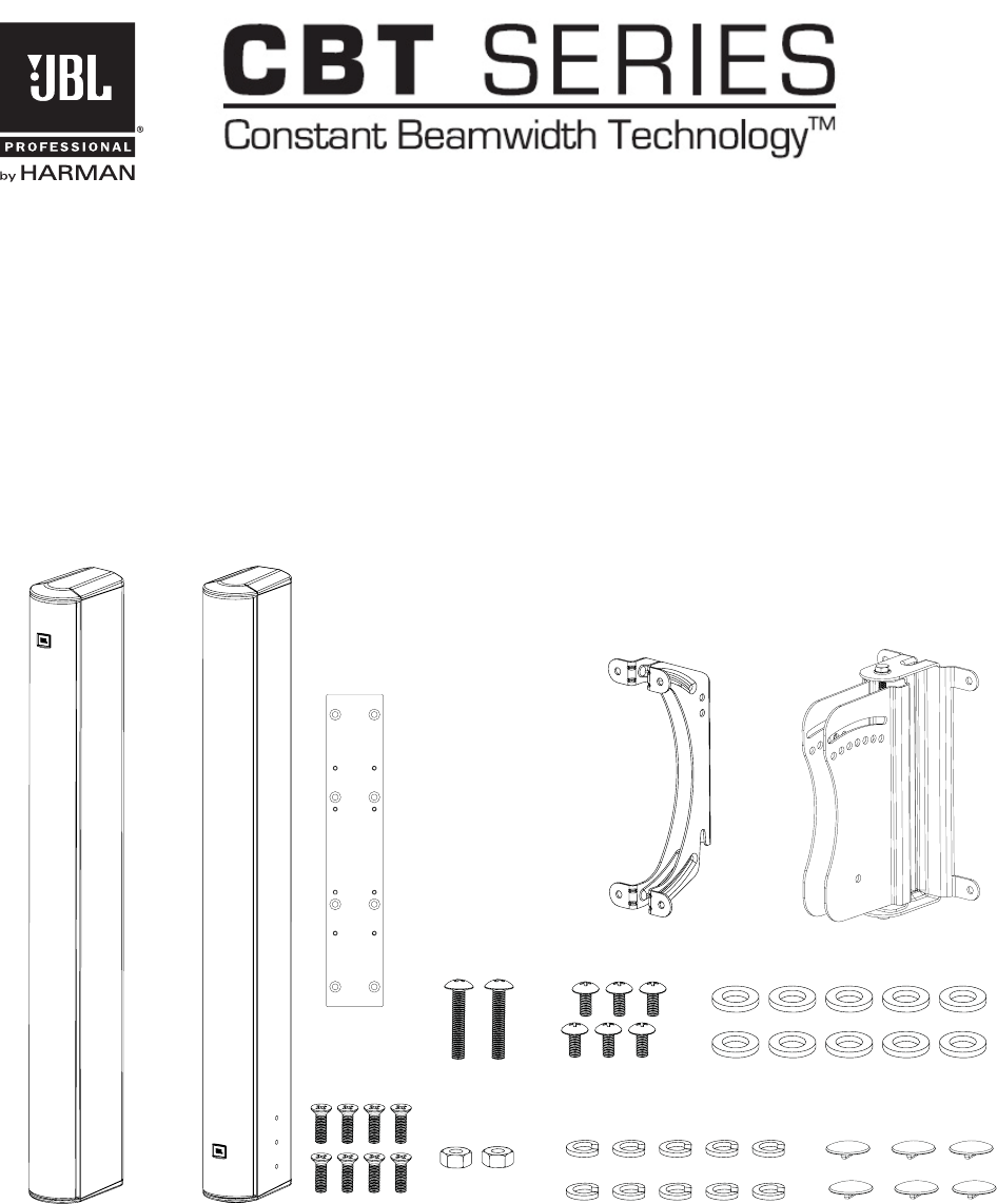
INCLUDED:
T
op Speaker
Module
Bottom Speaker
Module
Coupler
Plate
Speaker
Bracket
Swivel-Tilt
Wall Bracket
M6-34L M6-12L SS Flatwashers
M6-20L
Flat head
M6-Nuts SS Lockwashers Switch covers
[Not shown to relative scale]
CBT 200LA-1 Assembly & Bracket Installation Guide – Page 2
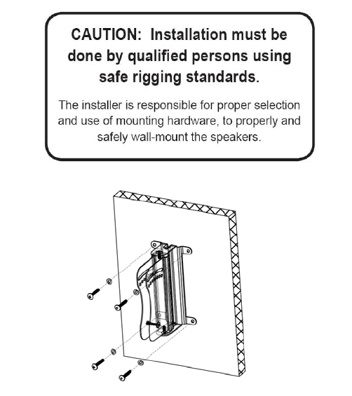
WALL SURFACE MOUNTING
Note that the BRACKET ASSEMBLY consists of a SPEAKER BRACKET and a WALL BRACKET.
1) RUN WIRING -- Run the wiring from the power amplifier to the location desired for mounting the
JBL CBT Loudspeakers.
2) ATTACH
WALL BRACKET TO WALL -- Using a level to ensure that the WALL BRACKET is
straight, secure the WALL BRACKET to the wall. Be sure to use the appropriate wall anchors for
attaching the bracket. Use all four screw holes for maximum integrity and safety. Be sure that the
slot feature is at the top.
Hardware for attaching WALL BRACKET to wall not included.

CBT 200LA-1 Assembly & Bracket Installation Guide – Page 3
3) ORIENTING TOP & BOTTOM SPEAKER MODULES
This drawing shows the proper orientation of the two speaker modules, where the coupler plate
attaches and where the wall bracket attaches (onto the coupler plate).
IMPORTANT: Note that the speaker will not work correctly if the TOP AND BOTTOM
SPEAKER MODULES are not oriented exactly as shown.
CBT 200LA-1
Assembly
1) Align Top & Bottom
Speaker Modules
So Arrows Point
at Each Other
2) Attach Coupler Plate
Using 8 Included
Flathead Bolts
For Bottom Module:
CAUTION:
Installation must be
done by qualified
persons using safe
rigging standards.
For Top Module:
CBT 200LA-1
Assembly
1) Align Top & Bottom
Speaker Modules
So Arrows Point
at Each Other
2) Attach Coupler Plate
Using 8 Included
Flathead Bolts
CAUTION:
Installation must be
done by qualified
persons using safe
rigging standards.
CBT 200LA-1
Assembly
1) Align Top & Bottom
Speaker Modules
So Arrows Point
at Each Other
2) Attach Coupler Plate
Using 8 Included
Flathead Bolts
CAUTION:
Installation must be
done by qualified
persons using safe
rigging standards.
CBT 200LA-1
Assembly
1) Align Top & Bottom
Speaker Modules
So Arrows Point
at Each Other
2) Attach Coupler Plate
Using 8 Included
Flathead Bolts
CAUTION:
Installation must be
done by qualified
persons using safe
rigging standards.
Coupler Plate
(8 flathead bolts)
Switches at the End of the Column
Switches at the End of the Column
Labels Show Orientation and Gives Instructions
(Point Arrows Toward Each Other)
Swivel/Tilt
Wall Bracket
(4 panhead bolts)
TOP SPEAKER MODULE
BOTTOM SPEAKER MODULE
CBT 200LA-1 Assembly & Bracket Installation Guide – Page 4
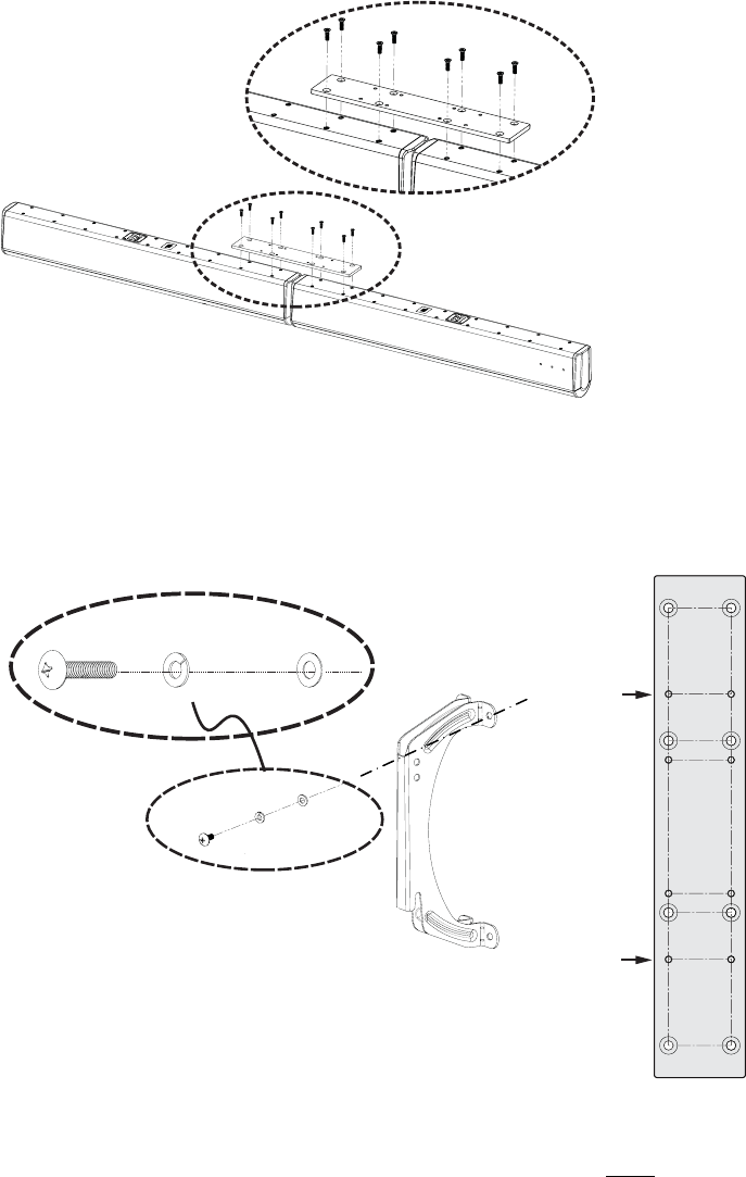
4) CONNECT SPEAKER MODULES TOGETHER VIA COUPLER PLATE
Attach COUPLER PLATE to the TOP AND BOTTOM SPEAKER MODULES, as shown, with 8
pcs of M6-20L flathead bolts, through to TOP AND BOTTOM SPEAKER MODULE’S rear
cabinet insert points.
5) ATTACH SPEAKER BRACKET TO 4 THREADED HOLES ON COUPLER PLATE
Attach Speaker Bracket to the 4 indicated threaded points on the Coupler Plate using the
included M6-12L (6 mm diameter, 12 mm long) bolts, with lock washers and flat washers.
Threaded points
for attachment of
Wall Bracket
(use included
M6 x 12 mm
pan-head bolts)
Threaded points
for attachment of
Wall Bracket
(use included
M6 x 12 mm
pan-head bolts
IMPORTANT: Because of the height of this speaker, the speaker bracket MUST be
installed to these threaded points on the Coupler Plate. Do NOT install the bracket
to any other positions on the speaker.
Speaker Section of
Speaker/Wall Bracket
Assembly
M6L12
BOLT
LOCK
WASHER
FLAT
WASHER
[4 Places]
Coupler Plate
(already installed on speaker)
CBT 200LA-1 Assembly & Bracket Installation Guide – Page 5
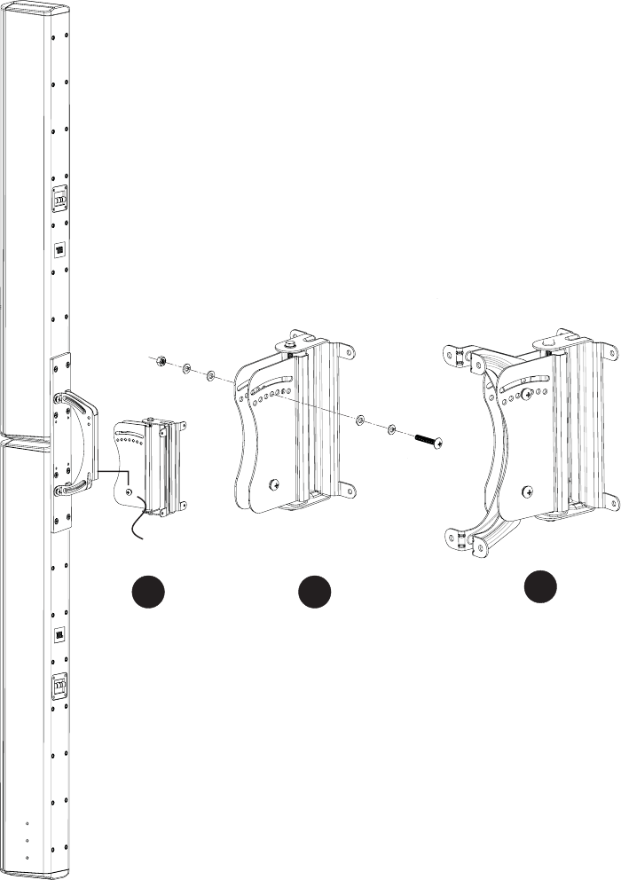
6) SLIDE SPEAKER WITH
SPEAKER BRACKET ONTO WALL BRACKET
n Once the wall mount has been attached to the wall and speaker mount has been attached
to the speaker, loosely install the M6-L34 PIVOT BOLT (bolt, lock washer and flat washer on
one side and flat washer, lock washer & nut on the other side) of the WALL BRACKET. Then
slide the speaker so that the SPEAKER BRACKET engages into the WALL BRACKET,
dropping the hook slot of the SPEAKER BRACKET onto the PIVOT BOLT (which will already be
installed loosely in the WALL BRACKET), as shown in Drawing n .
2
13
FLAT
WASHER LOCK
WASHER M6-34L
BOLT
FLAT
WASHER
LOCK
WASHER
M6 NUT
PIVOT BOLT LOCATION
[Same hardware order
for both bolts]
CBT 200LA-1 Assembly & Bracket Installation Guide – Page 6
o Insert the top tilt-angle bolt through the appropriate hole – one of the preset angle holes or the
slot for continuous adjustment capability (see below for more information about tile angles).
Install with M6-L34 bolt, lock washer and flat washer on one side and flat washer, lock washer &
nut on the other side, as shown in Drawing o . Make sure bolt goes through holes in WALL
BRACKET and in SPEAKER BRACKET.
p Final BRACKET ASSEMBLY is shown in Drawing p .
TIGHTEN THE BOLTS.
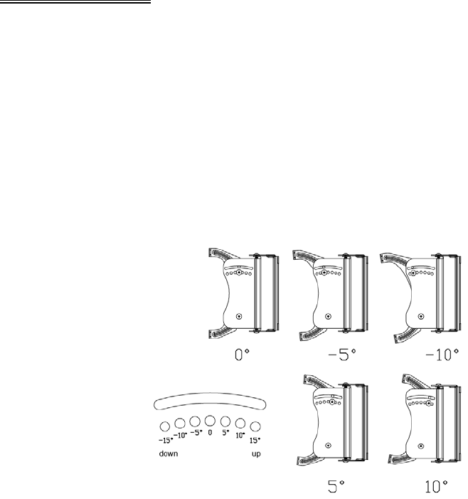
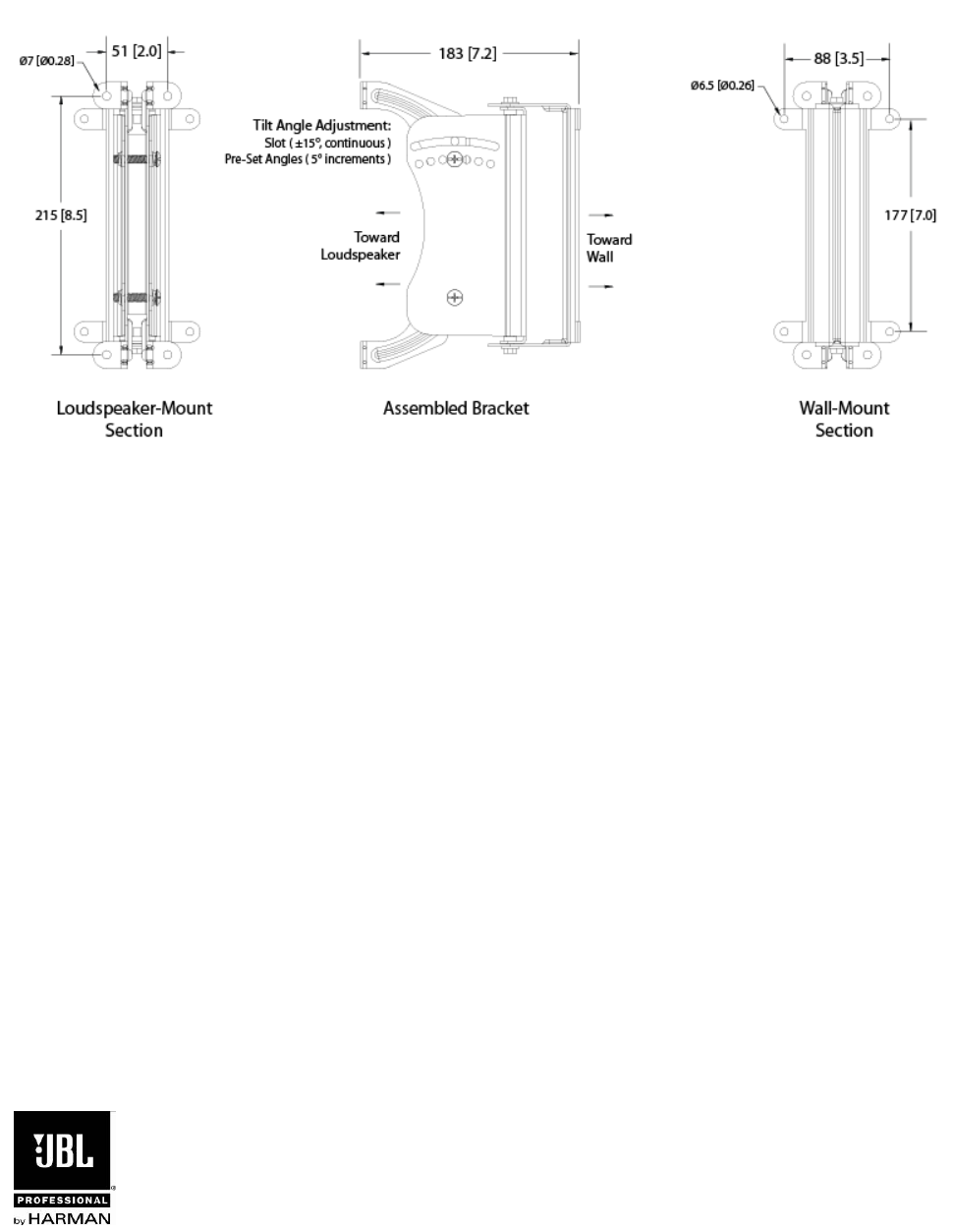
7) MORE ABOUT TILT ANGLES -- The bracket allows for +/-15 degrees of up or down tilt, however
because of the height of this speaker, the end of the speaker hits the wall at any angle greater
than 10 degrees.
PRE- SET ANGLES and CONTINUOUSLY VARIABLE ANGLE -- The bracket has through holes
for mounting angles of +/- 15 degrees in 5 degree increments. There is also a slot above the set of
holes for continuously variable adjustment. The pre-set angles are recommended for accurate
aiming in 5 degree increments and the slot for any angle between 5 degree increments. Either
can be utilized for setting the speaker’s tilt angle.
8) SET THE SWIVEL (PAN) ANGLE – Loosen the top and bottom bolts on the pivot. Adjust the
side-to-side swivel (ie, pan) aiming angle of the speaker. Tighten the bolts securely.
Maximum Swivel Angles before Wall Interference – The bracket swivels a full 90 degrees from
side-to-side, however when mounting the CBT speaker onto a wall, the side-to-side swivel is
limited by the end of the speaker encountering the wall. The maximum swivel angle depends on
the up/down tilt angle setting.
9) SAFETY CABLE -- Attach a safety cable (not included) to any of the 6 mm inserts on the back of
the CBT 200LA-1 cabinet using one of the extra included M6 bolts or via an M6 forged shoulder
steel eyebolt. Attach the other end of the cable to a secondary attachment point on the wall.
10) SWITCH COVERS – To discourage tampering with the switch settings, adhesive switch covers are
provided. Peel off the backing from the switch cover and stick the cover over the switch shaft,
lining up the ridge with the recess in the switch shaft.
CBT 200LA-1 Assembly & Bracket Installation Guide – Page 7
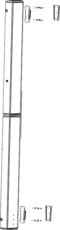
11) USING OPTIONAL MTC-CBT-FM1 FLUSH-MOUNT WALL BRACKETS – The optional MTC-
CBT-FM1 brackets allow installing the speaker with its back very close to the wall. It is
recommended to use two brackets – one on the top and one on the bottom – for stability.
CBT 200LA-1 Assembly & Bracket Installation Guide – Page 8
CBT 200LA-1 Bracket Dimensions
CBT200 Install
07/12
JBL Professional
8500 Balboa Blvd.
Northridge, CA 91355
USA
