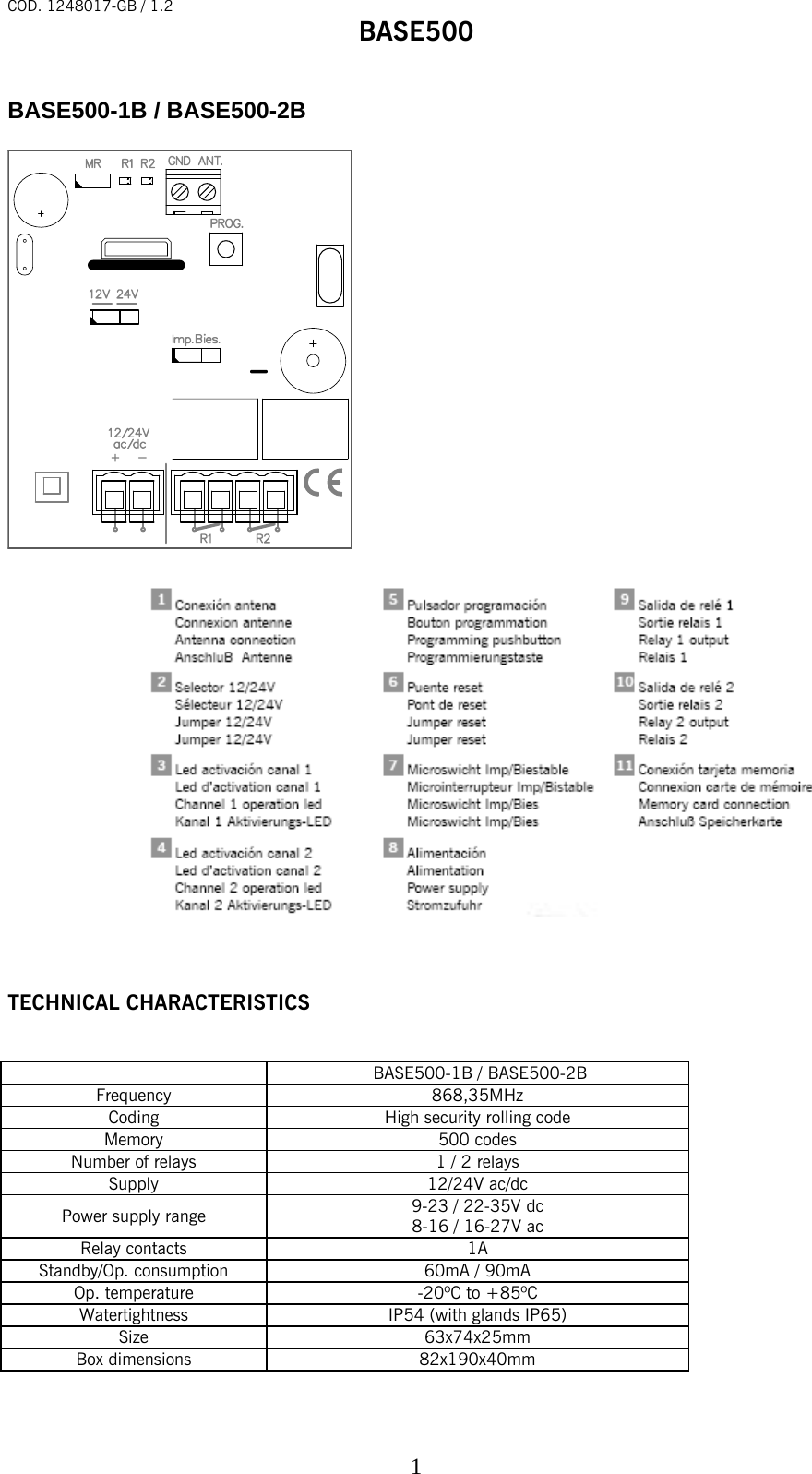
JCM Technologies BASE5001B-2B Receiver for security gate system User Manual 1248017 GB BASE500 v1 2

JCM Technologies, S.A. Receiver for security gate system 1248017 GB BASE500 v1 2

User Manual

COD. 1248017-GB / 1.2 BASE500   1 BASE500-1B / BASE500-2B                    TECHNICAL CHARACTERISTICS        BASE500-1B / BASE500-2B Frequency 868,35MHz Coding  High security rolling code Memory 500 codes Number of relays  1 / 2 relays Supply 12/24V ac/dc Power supply range  9-23 / 22-35V dc 8-16 / 16-27V ac Relay contacts  1A Standby/Op. consumption  60mA / 90mA Op. temperature  -20ºC to +85ºC Watertightness  IP54 (with glands IP65) Size 63x74x25mm Box dimensions  82x190x40mm
COD. 1248017-GB / 1.2 BASE500   2 INSTALLATION AND CONNECTIONS  Attach the rear part of the housing to the wall using the plugs and screws supplied. Pass the cables through the bottom of the receiver. Connect the power cables to the terminals marked in the mother board, as indicated. Fix the receiver front to the rear part using the screws supplied.   OPERATING  The pilot lights are activated every 5 seconds to indicate the correct supply of power to the equipment. Upon receiving a code, the receiver checks whether it is in its memory, activating the corresponding relay. The relay activation mode is selected in either impulse or ON/OFF using the Imp/Bies jumper (only with the relay 2). For adjustment of relay 1, see manual of the programming tool.    PROGRAMMING  MANUAL PROGRAMMING  Press the receiver programming button for 1 sec. and an acoustic signal will be heard. The receiver will enter standard programming (see table). If the receiver programming button is held pressed down, the receiver Hill enter special programming, cyclically passing from one configuration to the next. Once the programming configuration for the transmitter to be registered has been chosen, send the code to be programmed by pressing the transmitter. Every time a transmitter is programmed, the receiver will issue an acoustic signal for 0.5 sec. After 10 seconds without programming or pressing the first two transmitter buttons, the receiver will exit programming mode, issuing two acoustic signals of 1 sec. If upon programming a transmitter the receiver memory is full, it will issue 7 acoustic signals of 0.5 sec. and exit programming.   Configuration of transmitter programming in the receiver.  Led R1  Led R2 Standard Programming (default option, the receiver is always configured on pluri-channel)    The relays are activated 1st relay by channel 1  and 2nd relay by channel 2 (3rd relay by channel 1 and 4th relay by channel 2) Flashing   Flashing   Special programming   Press the transmitter channel to activate the relay 1 on the receiver  ON  OFF Press the transmitter channel to activate the relay 2 on the receiver  OFF  ON Press the transmitter channel to activate the two relays at once *  ON  ON  • If working in ON/OFF activation mode, relay 1 will act as impulse and relay 2 as ON/OFF. Therefore, on the first press relay 1 will close and open the contact and relay 2 will only close. On the second, relay 1 will close and open the contact and relay 2 will open.  N.B.: Each transmitter can be configured independently on the receiver.
COD. 1248017-GB / 1.2 BASE500   3TOTAL RESET  In programming mode, the programming button is held down and the “MR” reset jumper is bridged for 3 secs. The receiver will issue 10 short acoustic warning signals followed by others at a faster pace to indicate that the operation has been successful. The receiver is now in programming mode. After 10 seconds without programming or quickly pressing the programming button, the receiver will exit programming mode, issuing two acoustic signals of 1 sec.  GROUPS   Receivers can be configured with a group (from 0 to 7) so that there is no interference when working near each other.    125kHz125kHz 868MHz125kHzC3- G1C2- G2C3- G1 G1 G2125kHz 868MHzC2- G1C2- G1C3- G2C2- G2C3- G2C1- G0C2- G0   C=channel G=group N.B. Group 0 enables all groups.   GROUP CONFIGURATION The configuration can be carried out with the programming tool or by self-programming as follows.
COD. 1248017-GB / 1.2 BASE500   4Self-programming After the receiver has been totally reset, it will be configured with the group of the first radio-programmed transmitter by enabling the hands free mode.   Exception: If the receiver has been configured using programming tools, the group may only be changed with the programming tool.    Operations On powering the receiver, the led R1 will flash the same number of times as the group number with which it is configured.     USE OF THE RECEIVER These receivers are designed for use as remote controls for garage doors. Their use is not guaranteed for directly activating any other equipment different to that specified.  The manufacturer reserves the right to modify equipment specifications without prior notice.   IMPORTANT ANNEX Disconnect the power supply before handing the unit. In compliance with the European Directive low-voltage electrical equipment, we hereby inform users of the following requirements: · For units which are permanently connected, an easily accessible circuit-breaker device must be built into the wiring system. · This unit must always be installed in a vertical position and firmly fixed to the structure of the building. · This unit must only be handled by a specialised installer, by his maintenance staff or by a duly trained operator. · The instruction manual for this unit must always remain in the possession of the user. · Terminals of maximum section 3,8mm2 must be used for the power supply connections. · Use time delayed fuses.   Hereby, JCM TECHNOLOGIES, S.A., declares that this BASE500-1B, BASE500-2B is in compliance with the essential requirements and other relevant provisions of Directive 1999/5/EC.   This device complies with Part 15 of the FCC Rules. Operation is subject to the following two conditions: (1) this device may not cause harmful interference, and (2) this device must accept any interference received, including interference that may cause undesired operation. To comply with FCC rules, adjustment or modifications of this receiver and/or transmitter are prohibited, except for changing the code setting or replacing the battery. THERE ARE NO OTHER USER SERVICEABLE PARTS. Any other changes made, not expressly approved by JCM Technologies, S A could void the user’s authority to operate the equipment.   CE DECLARATION OF CONFORMITY See web www.jcm-tech.com

Navigation menu