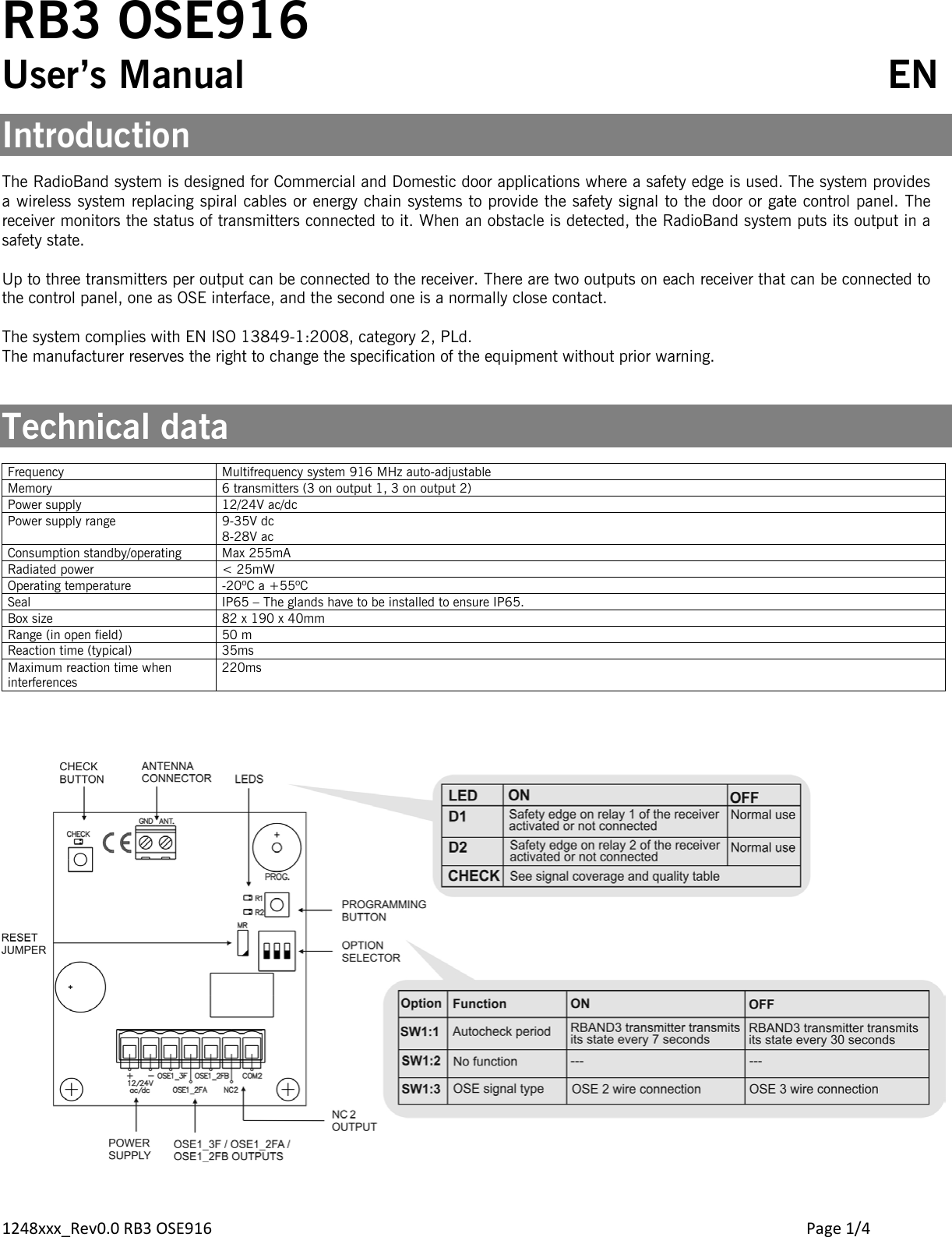
JCM Technologies RB3OSE916 Transceiver for Automatic Door Safety Edges User Manual

JCM Technologies, S.A. Transceiver for Automatic Door Safety Edges

User Manual

1248xxx_Rev0.0 RB3 OSE916        Page 1/4 RB3 OSE916 User’s Manual             EN  Introduction  The RadioBand system is designed for Commercial and Domestic door applications where a safety edge is used. The system provides a wireless system replacing spiral cables or energy chain systems to provide the safety signal to the door or gate control panel. The receiver monitors the status of transmitters connected to it. When an obstacle is detected, the RadioBand system puts its output in a safety state.  Up to three transmitters per output can be connected to the receiver. There are two outputs on each receiver that can be connected to the control panel, one as OSE interface, and the second one is a normally close contact.   The system complies with EN ISO 13849-1:2008, category 2, PLd. The manufacturer reserves the right to change the specification of the equipment without prior warning.   Technical data  Frequency Multifrequency system 916 MHz auto-adjustable Memory 6 transmitters (3 on output 1, 3 on output 2) Power supply 12/24V ac/dc Power supply range  9-35V dc 8-28V ac Consumption standby/operating Max 255mA Radiated power < 25mW Operating temperature -20ºC a +55ºC Seal IP65 – The glands have to be installed to ensure IP65. Box size 82 x 190 x 40mm Range (in open field) 50 m Reaction time (typical) 35ms Maximum reaction time when interferences 220ms
1248xxx_Rev0.0 RB3 OSE916        Page 2/4 Connection  OSE 3 wire connection    OSE 2 wire connection     Starting up  Mechanical installation Fix the back of the box to the wall, using the wall plugs and screws supplied. Install the receiver, close to the door and avoid metal surfaces between the receiver and the transmitter. The transmitter and receiver antenna must be parallel to each other for optimum signal reception. Pass the cables through the bottom of the receiver. Connect the power cables to the terminals of the printed circuit, following the indications of the connections diagram. Store transmitters. Fix the front of the receiver to the back with the screws supplied for the purpose.  Programming transmitter to receiver The receiver allows programming 6 transmitters (3 for Relay 1 and 3 for Relay 2). Each safety edge transmitter must be learnt into the appropriate channel of the safety edge receiver. A transmitter should only be connected to one receiver.  Press PROG button and keep pressed until desired mode selected. Programming of one safety transmitter (IN1 input)  Mode Configuration of transmitter programming in the receiver. Led R1 Led R2 1 Safety edge activates relay 1 on the receiver ON OFF 2 Safety edge activates relay 2 on the receiver OFF ON 3 Safety edge activates the two relays 1 and 2 at the same time ON ON Programming of two safety transmitters (IN1 and IN2 input)  Mode Configuration of transmitter programming in the receiver. Led R1 Led R2 4 Safety edge in IN1 activates relay 1 and safety edge in IN2 activates relay 2  Flashing  Flashing
1248xxx_Rev0.0 RB3 OSE916        Page 3/4 PRESS RPROG PUSHBUTTON     LED TURNS ON                   PRESS TRANSMITTER PROG     ONE BEEP & PROGRAMMED           PRESS RPROG PUSHBUTTON     LED TURNS OFF & END PROG                            Check the correct operation Press each safety edge connected to assure that the appropriate relay on the receiver is activated.  If not, see the Leds and Beeps indication table, to check what is happening and how to solve it.   Maintenance  Leds and beeps indication table  R1/R2 Led Check Led Beeps Equipment Message / error Solution ON OFF No beeps RB3 T Detection of the safety edge Verify that the IN1/IN2 led of the RB3 T is at  ON when you press PROG button of RB3 T, to check the correct operation.  RB3 R Communication failure between RB3 R and RB3 T Verify the radio signal with the Check function. OFF OFF 4 beeps each 20 seconds RB3 R RB3 T low battery  Verify the batteries of the transmitter ON OFF 4 beeps each 20 seconds RB3 R RB3 T only one battery connected Verify and connect the second battery. OFF ON No beeps RB3 R Check function. See coverage and signal quality table. ---   System Check Press the receiver’s CHECK button for at least 1 second to enter check mode. The indicator light will come on and four beeps will be heard.  Perform a complete door opening and closing manoeuvre.  During the system check a beep will be heard every 1,5 seconds. To exit Check mode, press the CHECK button or wait 5 minutes. On exiting check mode, seven consecutive beeps will be heard and the indicator light will flash continuously. If the communication fails, halt the door manoeuvre and press the safety edges installed to detect what has failed.  Perform another system check until the result is correct. Press the safety edges Nº flashes  check led Signal coverage Result of check Solution Three consecutive beeps are heard 1 Very weak Safety edge failure Change the orientation of the transmitting-receiving aerials.  2 Weak OK The battery consumption will be higher A single beep is heard 3 Normal OK  A single beep is heard 4 Good OK  A single beep is heard 5 Very good OK
1248xxx_Rev0.0 RB3 OSE916        Page 4/4 Maintenance  Total reset In programming mode, keep the programming PROG button pressed down and make a bridge with the “MR” reset jumper for 3s. The receiver will emit 10 warning sound signals and then more at a faster frequency, indicating that the operation has been carried out. The receiver will stay in programming mode. If 10 seconds pass without programming a transmitter, the receiver will exit the programming mode, emitting two 1 sec beeps.  Replacing a transmitter If a transmitter becomes damaged the whole system must be reset and replaced, and non-damaged transmitters must then be re-programmed into the receiver. Important Annex Disconnect the power supply whenever you proceed to the installation or repair of the control panel. In accordance with the European low voltage directive, you are informed of the following requirements: · For permanently connected equipment, an easily accessible connection device must be incorporated into the cabling. · This system must only be installed by a qualified person that has experience with automatic doors/gates and knowledge of the relevant EU standards. · The instructions for use of this equipment must always remain in the possession of the user. · Terminals with a maximum section of 3.8mm2 must be used to connect the cables. Follow all the recommendations given in this manual to avoid serious dangerous to persons.    Regulations  EC Declaration of conformity See web www.jcm-tech.com/en/declarations/  JCM TECHNOLOGIES, S.A. declares herewith that the product RB3 OSE916 complies with the requirements of the 1999/5/ CEE R&TTE Directive, and complies with the fundamental requirements of the 2006/42/CE Machine Directive, 2004/108/EC Directive on electromagnetic compatibility and 2006/95/EC on low voltage, insofar as the product is used correctly.  The system complies with EN ISO 13849-1:2008, category 2, PLd.    FCC Information This device complies with Part 15 of the FCC Rules. Operation is subject to the following two conditions: (1) this device may not cause harmful interference, and (2) this device must accept any interference received, including interference that may cause undesired operation.  IMPORTANT! Any changes or modifications not expressly approved by the part responsible for compliance could void the user’s authority to operate this equipment.

Navigation menu