JOINT TECHNOLOGY JT600 Portable GPS Tracker User Manual BMK 12W
SHENZHEN JOINT TECHNOLOGY CO.,LTD Portable GPS Tracker BMK 12W
UserManual.wiki
>
JOINT TECHNOLOGY
>
JT600 User Manual
user manual
Navigation menu
Upload a User Manual
Namespaces
Wiki Guide
HTML
PDF
Info
Views
User Manual
Discussion / Help
Navigation

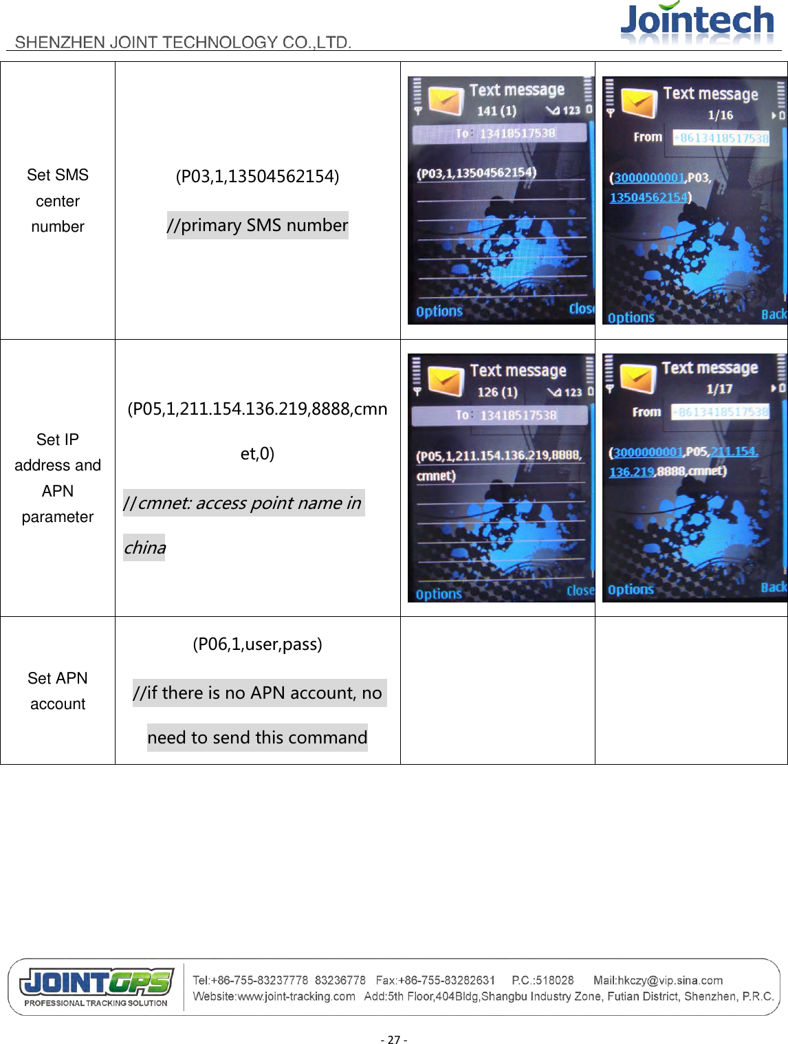
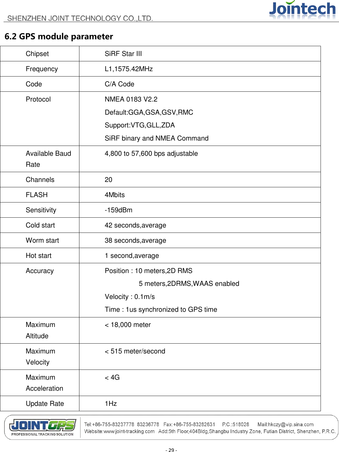
![- 20 - P01 Enquire the firmware version (P01) P02 Enquire current position (P02) P03 Enquire/Set SMS center number (P03,1,13919192020) / (P03,0) Parameter[1]: 1 means setting ,0 means enquiring Parameter[2]: 13919192020 means SMS center number. Don‟t be more than 15 digital numbers. P04 Enquire/Set Data uploading interval (P04,1,60,2) / (P04,1,120,0) / (P04,0) Parameter[1]: 1 means setting, 0 means enquiring Parameter[2]: 60 means 60 seconds ,uploading every 60 seconds Parameter[3]: 2 means uploading 2 times and then stops uploading data. If you input 0 ,It will upload data constantly via GPRS or SMS. Whether uploading via GPRS or SMS ,please refer to the P07 command. P05 Enquire/Set GPRS network parameters(IP address, Port) (P05,1,211.154.XXX.XXX,8000,CMNET,0) / (P05,0) Parameter[1]: 1 means setting, 0 means enquiring Parameter[2]: 211.154.XXX.XXX means IP address Parameter[3]: 8000 means TCP port Parameter[4]: CMNET means APN name .access point name at local. CMNET is example in china. Parameter[5]: 0 means the Data transmission is TCP. 1 indicates UDP P06 Enquire/Set APN username and (P06,1,user,pass) Parameter[1]: 1 means setting, 0 means enquiring](https://usermanual.wiki/JOINT-TECHNOLOGY/JT600/User-Guide-1506068-Page-20.png)
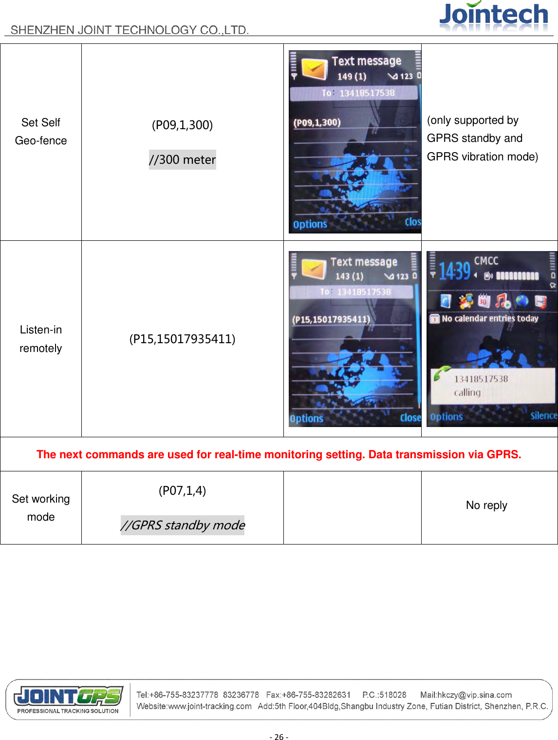
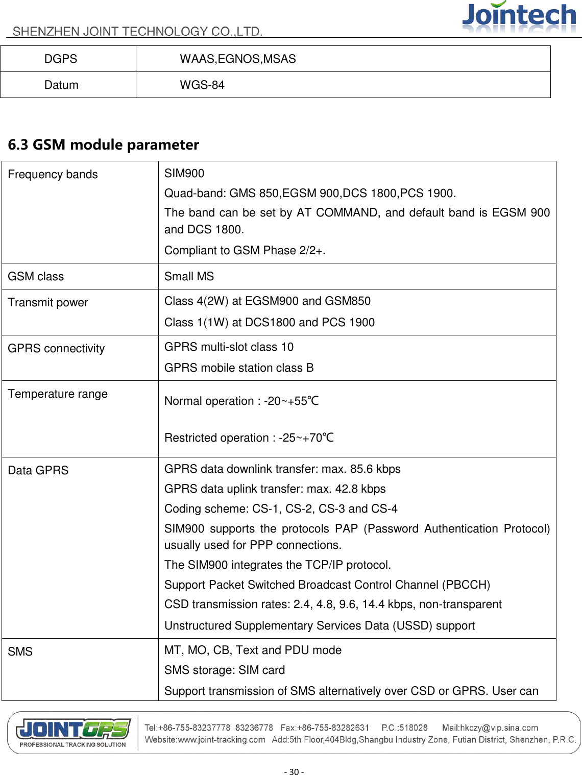
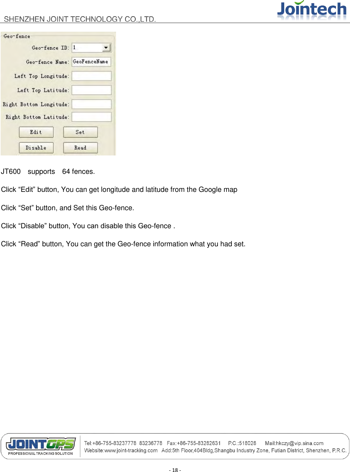
![- 21 - password Parameter[2]: user means APN username. User is a example. Parameter[3]: pass means APN password. Pass is a example. P07 Enquire/Set Working mode (P07,1,4) / (P07,0) Parameter[1]: 1 means setting, 0 means enquiring Parameter[2]: 4 means GPRS Standby mode. There are six modes. 1 SMS Standby mode 2 SMS Timing mode 3 SMS Vibration mode 4 GPRS Standby mode 5 GPRS Timing mode 6 GPRS Vibration mode P08 Enquire/Set Geo-fence (P08,1,1,11323.1234,2312.2321,11326.4312,2308.1233,area 1) Parameter[1]: 1 means setting, 0 means enquiring Parameter[2]: 1 means Geo-fence ID.JT600 supports 64 fences. Parameter[3]: 11323.1234,2312.2321,11326.4312,2308.1233 means 11323.1234 left top longitude, 2312.2321 left top latitude, 11326.4312 right bottom longitude, 2308.1233 right bottom longitude. It‟s a rectangular region. Please set Geo-fence by JT600 Assistant software. Parameter[4]: area 1 means Geo-fence name.](https://usermanual.wiki/JOINT-TECHNOLOGY/JT600/User-Guide-1506068-Page-21.png)
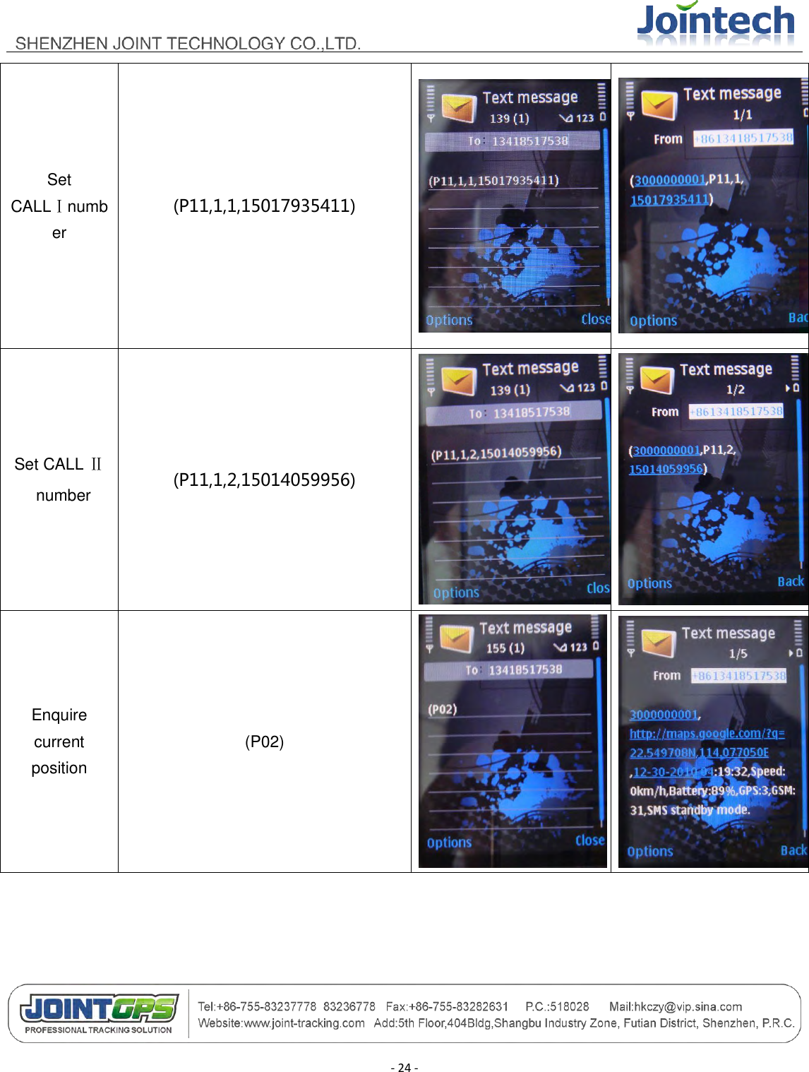
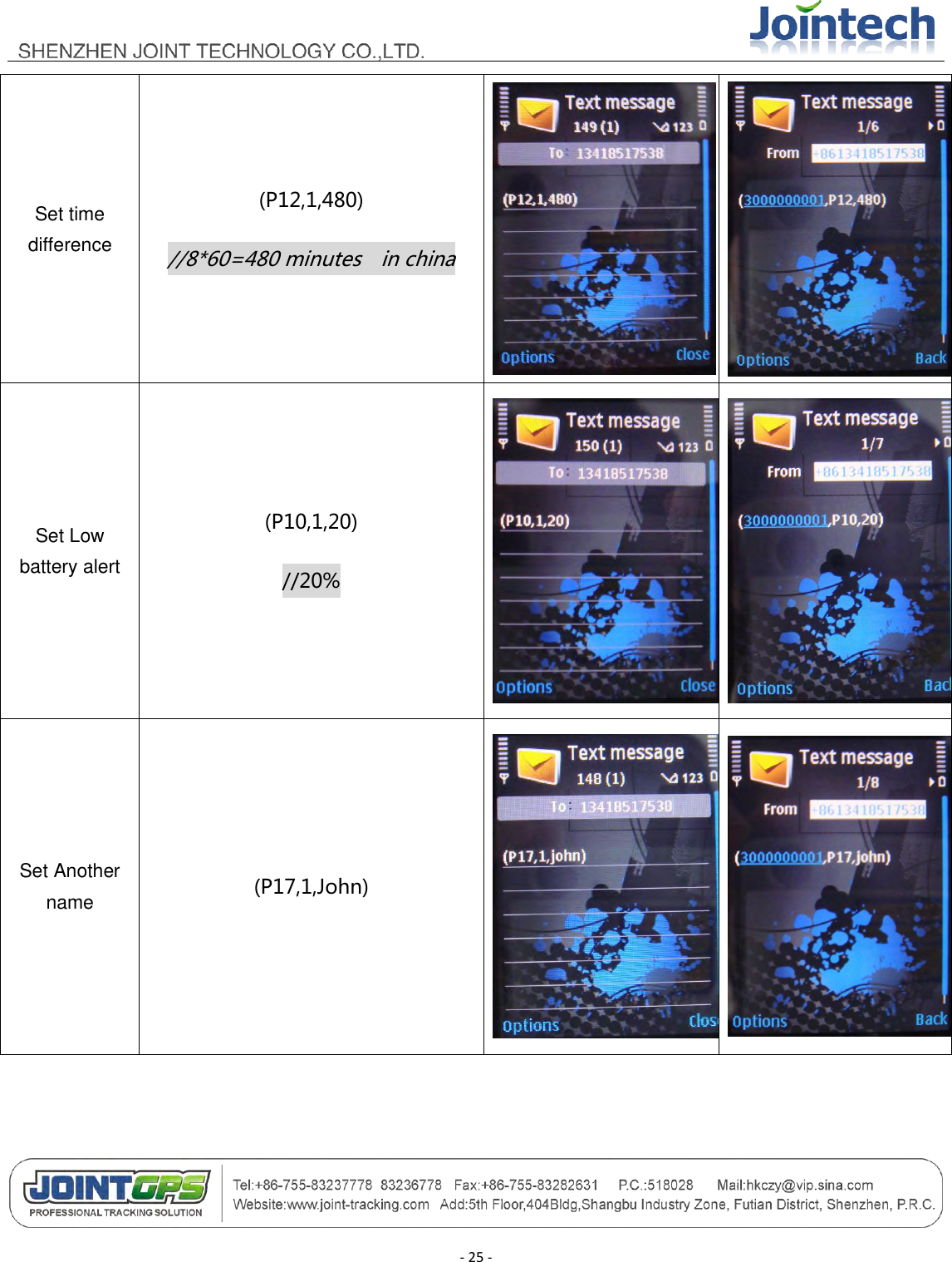
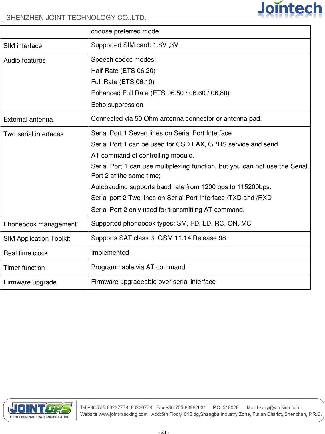
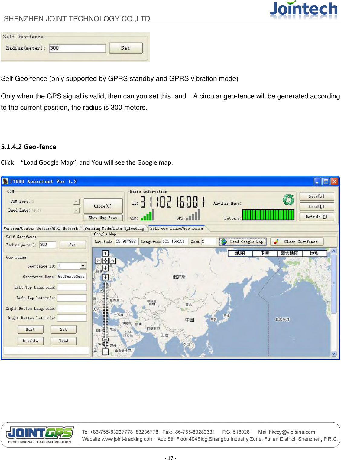
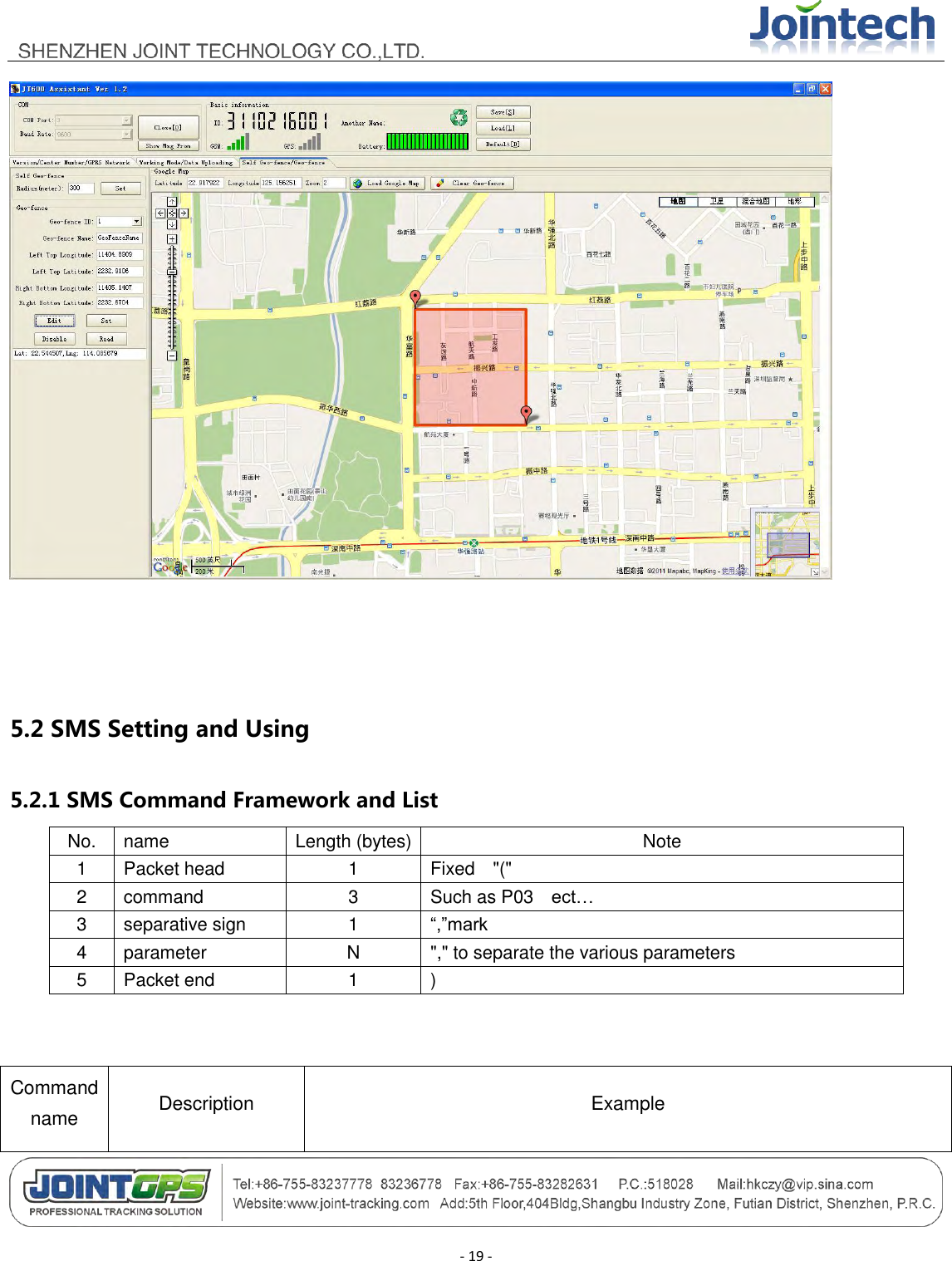
![- 22 - P09 Enquire/Set Self Geo-fence (P09,1,300) Parameter[1]: 1 means setting, 0 means enquiring Parameter[2]: 300 means 300 meters. Self Geo-fence (only supported by GPRS standby/GPRS vibration mode) Only when the GPS signal is valid, then can you set this .and A circular geo-fence will be generated according to the current position, the radius is 300 meters. P10 Enquire/Set Low battery alert (P10,1,20) Parameter[1]: 1 means setting, 0 means enquiring Parameter[2]: 20 means 20%. when the power percent of the battery is low than this. There would be a Low Battery alert. P11 Enquire/Set VIP numbers (P11,1,1,13910102345) / (P11,0,5) Parameter[1]: 1 means setting, 0 means enquiring Parameter[2]: 1 means the first VIP number(CALL Ⅰ).JT600 supports 5 VIP numbers. Parameter[3]: 13910102345 means Cell phone number P12 Enquire/Set time difference (P12,1,480) / (P12,0,480) / (P12,0) Parameter[1]: 1 means setting, 0 means enquiring Parameter[2]: 480 means 60*8=480 minutes. 480 is example. JT600 outputs Greenwich time. So we need to adjust it to your local time.](https://usermanual.wiki/JOINT-TECHNOLOGY/JT600/User-Guide-1506068-Page-22.png)
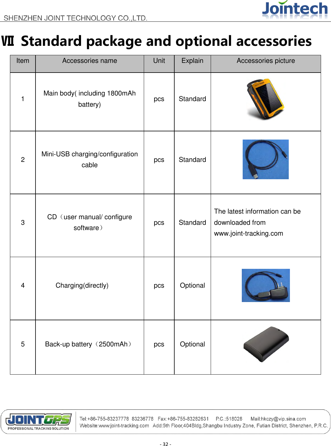
![- 23 - P13 Require SOS LED flashing (P13,1,1) / (P13,1,0) Parameter[1]: 1 means setting, 0 means enquiring Parameter[2]: 1 means open the SOS LED .0 means close the SOS LED. P14 Set ring volume (P14,1,5) / (P14,0,5) Parameter[1]: 1 means setting, 0 means enquiring Parameter[2]: 5 from 1 to 7. 1 indicates minimum volume. 7 indicates maximum volume. P15 Require Listen-in remotely (P15,13919192020) Parameter[1]: 13919192020 means cell phone number. After you send this command ,JT600 will call this number. P16 Enquire current battery (P16) P17 Enquire/Set another name (P17,1,jointech) Parameter[1]: 1 means setting, 0 means enquiring Parameter[2]: jointech means another name. jointech is a example. 5.2.2 Short Message Command Example Feature Command format example Send Short message command via cell phone Reply message from JT600](https://usermanual.wiki/JOINT-TECHNOLOGY/JT600/User-Guide-1506068-Page-23.png)