JSF Technologies SZ100 SCHOOL ZONE FLASHING BEACON User Manual users manual
JSF Technologies SCHOOL ZONE FLASHING BEACON users manual
users manual
School Zone Flashing Beacon Description and
Installation Instructions
Introduction
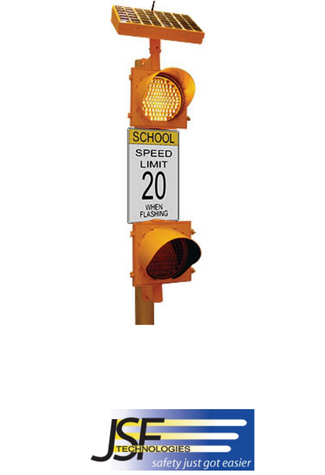
JSF Technologies’ School Zone Flashing Beacon is the most efficient system available on the market. Being
solar powered, the system installs in minutes on any pole with no electrical connection. The school district is
able to create an annual usage schedule or make immediate changes to the schedule from any location over the
Internet. The schedule is transmitted wirelessly to the units with the click of a mouse and the user receives e-
mail confirmation that the schedule was received.
The system is made up of one Primary unit (SZ 100) and any number of Satellite AB500 units ( FCC
ID:SFIAB500) for each school. The Primary receives and stores an entire years schedule information via
wireless “Narrow-Band PCS” communications across North America. Each time the system is scheduled to
flash, the Primary transmits “Turn On” and “Turn Off” messages to the Satellites, via 902-928 MHz spread
spectrum radio signal within a range of 1 kilometer. Each field adjustable network of school zone flashers has 8
addresses to ensure that systems at adjacent schools do not interfere with eachother. The system is available
with 8” or 12” signal lights.
Each School Zone (SZ100) unit consists of key parts:
1. The Solar Panel housing that contains
• Solar Panels: 4.5W, 6V, 12 ¾” x 5 1/8” per solar panel. Multiple panels used on some models.
• Antennas: Primary contains two antennas, Satellites contain one antenna. SZ100 units utilize a unique
reverse polarity SMA connector. The antenna is ANT-916-CW-HD ¼ wave Whip from Linx
Technologies. Gain of 3dBi. Primary and Satellite beacons communicate in a local RF network situated
up to 1000 metres from eachother.
• Batteries: 2V, 25Ah, BC cell. Multiple batteries used on some models.
• Control circuitry. Satellites contain one control box. (It is a actually standard AB500 Active Beacon unit
that are working only in receive mode.) Primary contains two control boxes. One of them is a standard
AB500 module and the second one is a School Zone Flasher unit that has a FCC approved Advantra
pager module and a CC1010 based spread spectrum 900Mhz transmitter. When SZ100 unit transmits the
signals ON or OFF the AB500 receives the signal through the leakage of RF energy from SZ100 unit.
The satellite units receive the signal through the antennas. The Printed Circuit Board (SZ100) controller,
which includes a CC1010 complete RF System-on-Chip solution, Narrow-Band PCS module, real time
clock (RTC) and memory chip. Memory holds a one-year school schedule. The memory can be
transferred through a serial port or by the Narrow-Band PCS system. The CC1010 integrates a low-
power 300-to-1000 MHz RF transceiver and an 8051-compatible micro-controller. The PCB is installed
inside of aluminum housing to reduce EMI. Switches installed on the PCB allow the installer to
configure the network address and LED flash pattern. DC-to-DC circuitry converts energy from
Batteries, Solar Panels to provide voltage levels compatible with the multiple LED Arrays and battery
charging. The CC1010 microcontroller runs on two clock frequencies 32.768 kHz and 14.7456 MHz and
controls all functions required to integrate RF communication, charging and LED flashing. The CC1010
is equipped with fully programmable, fast-settling frequency synthesizer.
The two frequency registers are designed such that the “next” frequency can be programmed while the
“present” frequency is used. The switching between the two frequencies is done through the special
register. During synchronization when Rx receives a “right” signal it knows what the next frequency
will be looking at the frequency table. The receiver and the transceiver from the moment of the
capturing synchronously follow the frequency table.
The 51 frequencies are used in a unique predefined pseudo-random sequence. In the simple example
below, the five frequencies are used in the sequence 902.5, 914.0, 914.5, 910.0, 919.5 MHz.
For communication to take place, the transmitter and receiver must use the same frequency:
902.5MHz
914MHz
914.5MHz
910MHz
919.5MHz
910.5MHz
913.5MHz
925MHz
911.5MHz
912MHz
917.5MHz
907.5MHz
903.5MHz
927MHz
926MHz
922MHz
909.5MHz
905.5MHz
919MHz
911MHz
915MHz
913MHz
918.5MHz
925.5MHz
905MHz
909MHz
921.5MHz
915.5MHz
924.5MHz
903MHz
916MHz
904.5MHz
916.5MHz
917MHz
920MHz
918MHz
908.5MHz
923MHz
907MHz
927.5MHz
920.5MHz
921MHz
904MHz
906.5MHz
908MHz
926.5MHz
922.5MHz
906MHz
924MHz
923.5MHz
912.5MHz
The receiver IF bandwidth is 175 kHz matching the transmitted signal of 64 kHz-frequency separation. The
maximum output power of transmitter is 20dBm.
The Primary Beacon is installed on the top of 2 - 3meter pole so the distance between the antenna and
people satisfy power RF density limit.
Long-life battery capacity. The system is trickle charged during daylight hours, even in cloudy conditions.
On a full charge, the system will operate at the rated usage for over one month without any solar charging.
2. One or two individual 8” or 12” light heads: “A” and “B” containing high efficiency LED light modules.
The activation signal ON is received by Satellite beacons in the vicinity of the Primary with the same
address. The beacons will flash until OFF signal is received.
Installation
Each unit is packaged in separate boxes, with a number of individual parts:
• Bundle of individual batteries
• Upper light head “A” with mounting bracket
• Lower light head “B” with mounting bracket
• Solar panel housing
• Light face bonnets
1. We will start by installing the batteries into the Solar Panel Casing on your workbench. Remove the bolts
on the solar panel casing and remove the top. Be careful because there are wires from the solar panels on
the top of the casing to the control box on the bottom of the casing.
Next, pull the batteries, AS A GROUP, out of the battery box. Lay the batteries down flat on your
workbench so that you have all batteries in an orderly row. In the middle of the batteries you will find a
single unconnected trailer connector painted yellow on one side.
Open the Velcro straps in the solar panel casing. Lay the batteries in position and close the Velcro straps
tightly.
Connect the trailer connector from the battery bundle to the trailer connector in the solar panel casing. Both
connectors are painted yellow on one side.

2. Next we will set the control box to the appropriate settings. There are two dials on the control box. If you
have installed two or more systems within 2 kilometers, change the network address on all beacons on either
system so they do not interfere with eachother. Then, set the flash pattern for each beacon as follows:
Flash
Pattern High Visibility
Strobe
Or
50/50
Between Heads on a
single AB-7400 unit
0 HVS Synchronized – A
1 HVS Synchronized – B
2 HVS Wig/Wag – A
3 HVS Wig/Wag – B
4 50/50 Synchronized – A
5 50/50 Synchronized – B
6 50/50 Wig/Wag – A
7 50/50 Wig/Wag – B
3. You may now place the top back on the solar panel casing and bolt it loosely in place. We will need access
inside this casing again once we have installed it on top of the pole.
Now we are ready to move out to the location where you will be installing the lights.
4. The
Upper Light Head with Mounting Bracket must be installed first. The light head hangs below the
bracket, and may hang partially over the sign. The brackets are designed to be installed on any type of pole
by: strapping the bracket to the pole; or bolting the bracket using existing holes in the pole; or drilling and
tapping new holes in the pole. Remember that this unit is heavy, so must be very secure.
If using a hollow pole, drill a hole in the pole at the back of the bracket and pass the long brown & orange
wires through the hole before bolting the bracket to the pole. Allow the brown & orange wires to drop
down the pole to another hole where the bottom bracket will be placed. If not using a hollow pole the back
of the bracket has a slot to contain the wires. For protection the wires should be placed between the sign
and the pole or in a conduit.
Open the upper light face and remove any packing materials. Check to ensure the wires inside the light
head are securely attached.
5. Next, install the Lower Light Head with Mounting Bracket in a similar manner, however in this case the
light head stands above the bracket. You will need to retrieve the brown & orange wires from the pole and
pull them through the lower bracket into the light head before tightening the bracket to the pole.
Next, open the lower light face, remove the packing materials, and attach the brown & orange wires to their
appropriate places, directly opposite the existing brown & orange wires already in the light head. Close the
light face.
6. The
Solar Panel Casing can now be mounted on top of the Upper bracket. As you are doing so, push the
two pairs of wires that are currently sticking out of the top of the upper light head: brown & orange, and
gray & yellow, into the solar panel casing through the bottom collar. Once you have placed the solar panel
casing loosely on top of the upper bracket, turn the solar panels to face the South to maximize solar energy.
Tighten the collar retaining bolts.
You will now need two people working at the top of the pole. Open the solar panel casing and have one
person hold the top open while the other performs the following task. Attach the brown & orange and
yellow & gray wire pairs to their appropriate spots, directly opposite their matching color.
7. Install the Primary and Satellite beacons in a similar manner. After all beacons at a school have been
installed, log onto your account within the JSFtech.com web site to test the system.
Battery Replacement
• Open the solar panel housing.
• Disconnect the battery power connector (this is a black trailer connector painted with yellow).
• Release the Velcro straps.
• Remove the batteries.
• Re-use the wires, nuts and rubber cap.
• Ensure that the polarity of the wire matches the polarity of the battery terminal. (Red to +).
• Secure the new batteries back in the solar panel housing with the Velcro straps.
Understanding Smart Software
During extended sunny periods, JSF’s Smart Software uses the extra solar energy to increase flash strength.
During extended overcast periods or snow cover, Smart Software dims the lights and reduces strobe frequency
to ensure the beacon remains active as long as possible. Therefore, regardless of flash pattern, after an extended
period of heavily overcast weather, you may see the unit move to 3 strobes or 2 strobes per cycle. The system is
performing exactly as it was designed. It will come back up to full power with just a day or two of sunny
weather. If the unit drops down to 1 strobe per cycle, it is still performing as designed, but is an indication that
the system is in distress. Please contact us to discuss the situation.
Storage
Batteries loose their charge when stored for extended periods. Therefore, once per month you should top-up the
batteries. To do so, connect the red and white wires with the trailer connector. Then put the unit outside for a
couple of nice sunny days.
Warranty
1 year warranty on all parts and batteries. Vandalism is not covered by this warranty.
Troubleshooting
If you have any problems with the installation or maintenance of your beacon, please contact JSF Technologies
directly.
JSF Technologies Phone: 1-800-990-2454
6771 Kirkpatrick Crescent Fax: 1-800-576-7899
Saanichton, BC, Canada E-mail:AEvans@JSFTech.com
V8M 1Z8 Web: JSFTech.com