JSW Pacific CCD-401S Wireless Color Miniature Weatherproof Camera User Manual
JSW Pacific Corporation Wireless Color Miniature Weatherproof Camera Users Manual
UserManual.wiki
>
JSW Pacific
>
CCD 401S User Manual
Users Manual
Navigation menu
Upload a User Manual
Namespaces
Wiki Guide
HTML
PDF
Info
Views
User Manual
Discussion / Help
Navigation
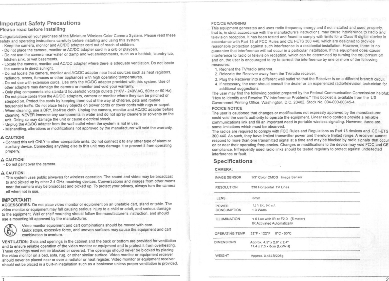
![Installing the Miniature Wireless Color Camera SystemToinstallthe system, follow these steps:Receiver:1. Plug the AC/DC adapter cord into the DC input jack on the back ofthe receiver.2. Plug the audlolvldeo cord to the anulo!v1deo output jack of the receiver. Plug the other end of theto the audiolv1deo input jacks on your TV or monitor.3. Plugthe nv ACIDC adapter Inlo a(110V-.240V) outlet The power indicator LEDlocated on the top of the reoelverCamera:1. Plug the 7.5VAcmc adapter cord into Ihe DC input jack on the back of the camera.2. Plug the adapter inlo a standard (110V-240V) AC outletSystem Setup:1.Selectthe channel(Channel1'-4) 10 be used onboththe cameraand receiver.NOTE: Make sure the camera and receiver are set to the same channel (1, 2,3 or 4).2. Set the selected channel by gently pushing the dip-switch for that channel 10the ON position onboth the camera and the receiver.For example, to set both the camera and receiver on 1:(a) Push the Channel 1 dip-switch located on the bottom l.'1]the camera and the receiver to the ON position. 1 ;1 34(b) Make sure the remaining dip-switches are In the OFF Carn Set 10position. In this case, channels 2, 3 and 4 should be In Chan~:'1the OFF position.Ifmore than one camera is to be installed and operated at the same time:Simply follow steps (a) and (b) and set thedip-switches for the other channels on thecamera and receiver to ON.For example, to operate two cameras: setCamera 1 to Channel 1 (other channels off) Camera1 Camera2, Set to Set tosetCamera 2 to Channel 2 (other channels off), Channel 1 Channa! 2£1110on the rflceiller, set channels 1 and2 to ON.See "Camera and Receiver Selting Chart" below for more detailed Instructions.3. Position the camera antenna toward the receiver antenna. Rotate/adjust the antennas on both thecamera and receiver for best performance.Additional Notice- When installing the camera, check the reception of the receiver before finalinstallation. Have someone hold the camera in the area to be monitored and another person to checkthe receptionWithyourTV or monitor. If interferenceor other problemsC)CCUr,refer to theTroubleshooting Guide.1.-. i III1;13 .. ['jJ III1 2 3 4 1 ;1 :I 4ReceiverSetto Channel1&2Camera & Receiver Channel Setting Chart1. This 2,4 GHz system can be connected with up to "channels. Set channels on the camera and receiverbefore starting the system.2. Set camera and receiver channels by gently pushing theswitches Withan object such as a pen ar pencil to the ONor OFF position. Use the illustrations shown on !he rightas a guide. The switches are inset into the camera andreceiver housings to avoid accidentally changing thechannel settings.3. The Auto Sequential Scann."!; foOllure automaticallyactivates when more than one switch is set to' ON.Camera 1 Camera3CH1 Ii ! Iii 11CH312 3 4Camera 2 Camera 41/:.i,H CH2 II I I -, CH41234 1234ReceiverONTroubleshooting GuideON1 Year Limited Warranty:JSN'oIPacific Corp., !he meker of Navigator. brand products, warrants that for a pariodof 1 year fromthe date of purchase, this product will be free from defects in material and workmanship. JSW, at itsoption, will repair or replace this product or any component of the product found to be defective duringthe warranty period. Replacement will be made with a new or remanufactured product or component.If the product is no longer available,replacemern may be made with a similar product of equal orgreater value. This is your exclusive warranty. This warranty is valid for the original purchaser from thedate of initial purchase With JSW and is not transferable. This warranty does not cover norma! wear ofparts or damage resulting from any of the following: negligent use or misuse of the product, use onimproper voltage or current, use contrary to the operating instructions, disassembly, repair or alterationby anyone other than JSW or an authorized service center. Further, the warranty does not cover ac!$of God, such as lire, 110od, hurricanes and tomadoes or any batteries that are induded withthis unitJSW shall not be liable for any incidental or consequential damages caused by the breach of anyexpress or implied warranty.If the Cameraand/or Manitor... IYou should... iNo Power 1. Check that the power cord(s) Is properly connected.2, Checkthatthe monitar is turned ON.3. Wrong ACIDC adaotar used. Check Ihat the adapter labeledOUTPUT: 7.5Vt)C. is connected 10the w;I\:fL. and adapterlabeled OUTPUT:'51/DC is connected to thecamcrnNo sound or picture. 1. Check the channel switch settings on the camera(s) andDistorted sound or monitor. Make sure the channels match on both units.picture 2. SIgnal interference from a microwave oven. Check if amicro-wave oven is in use Orlocated in the path betweenthe camera and monitor. If so, tum it off or move it aut ofthe path.3. Signal interference from other signal producing devices.(a) Change the channel setllng on both camera and monitor.(b) Identify and eliminate the source of the inlerference.(0) Relocate the camera and/or monitor closer 10 eacholher.4. Camera and monitor are too far apart. Relacate the cameraand/or monitor5. Antennais positioned improperly. Adjust the antenna on thecamera and/of monitor.](https://usermanual.wiki/JSW-Pacific/CCD-401S/User-Guide-606817-Page-5.png)