JSW Pacific CCD-401S Wireless Color Miniature Weatherproof Camera User Manual
JSW Pacific Corporation Wireless Color Miniature Weatherproof Camera Users Manual
Users Manual
II
-
Navigator"
User's Manual
Model No.: CCD-401
Miniature Wireless Color Camera System
- Wireless Color Westherproof IP44 Camera with
Audio
PLEASE READ CAREFULLYAND SAVE
This manual contains important information about this product'soperation.
If you are installing this product for use by others you must leave this
manual -or a copy- with the end user.
Model No.: CCD-4Q1
Miniature Wireless Color Camera System
Important!
Please read this booklet carefully
before installing or using these units.
DANGER-HIGHVOLTAGE-These units
should ONLY be opened by an authorized
technician if service is required.
Contents
Safety Precautions
For correct and safe operation of this
system, it is essential that installers, end-
users and service technicians should follow
all safety procedures outlined in this
manual. Specific Warning and Caution
statements (and/or symbols) are marked on
the units where needed.
Warning and Caution Statements
"WARNING" indicates a situation where
failure to follow proper procedures can
cause personal injury.
"CAUTION" indicates a situation where
failure to follow proper procedures can
cause damage to the equipment.
Important Safety Precautions 1
Specifications ..2
Parts IncludedwithThis System ~.~ 3
Parts of the Miniature Wireless Color Camera
System :...... ..3
- Parts ofthe Camera 3
- Parts ofthe Receiver 3
. Installation 4
- Installing the Mounting Bracket
(Camera Stand) 4
- Installing and Aligningthe Camera
on the Mounting Bracket (Camera Stand) 4
-Rotating the Camera 4
-Installing the Miniature Wireless Color Camera
System 5
Troubleshooti n9 Guide 6
Warranty 6
Important Safety Precautions
Please read before In$talling
yourpurd1~se of th~ MiniatureWireless ColorCamera
IIinstructions beforeInstallin9and this
camera,monitorand cordoutof reach c
-Do not p'lac~thecamera,mollltor adaptercordin a alb or
-Do 110tuse the camera near wat~r or damp and wet environments, s
or wef basements,
- locate camera, monitor and ACJDC adapt~r where th~re is ad~quat~ ventUation, Do
the camera in direct sunlight
-Do nollocate the monitor and adapter near heal sou~s suCh as heal registers,
radiators, ovens, or oth~r operating
-Do with cords., Use only adapter
olher may damage the camara or tmd'void
components into standard voltage (110V -or 60 Hz),
I cords from the ACIDC adapters, camera or monitor wherethey can pinched or
Protect the cords them out of the of children, and routine
traffIC,Do not place with rugs or a
-lJVhen cleaning, use a DRY, lint-free camera., monitor adapter
cleaning, NEVER and do not spray solvents on the
unit,Do.ingso maydamage or cause electrical shook.,
-Unptug the ACIDC adapter from the wall outlet when Ihe i
-Mishandling, alterations or modifications nol approved by
Please read Ihese
locate
IsllotillUse,
the warranty,
A CAUTION!
-Conned this unit ONLY to other compatiblounits, Do not connect it.10any
auxiliary devica, Connecting any1bing else to this unit may damage it or
properly.
A CAUTION!
- Do not paint over the camera,
A CAUTIONI
- This system uses public airwaves for wireless
10 and pid<ed up by other 2,4 GHz rece
near the camera may be broadcast and
off when not in use.
Thesoundandvideomaybe broadcast
Conversationsand fromotherrooms
To protectyour privacy, turnthe camera
IMPORTANT!
ACCESSORIES- Do not place video monitor or equipment on an unsteble cart, sland or tablo, The
\/ideo monitor or equipment may fall causing serious injury to or adult, and serious damage
to the equipment Wall or shelf mounting should follow the manufacturer's instruction, and should
use a mounting kit approved by the manufacturer.
Video monitor equipment and cart combinations should be moved wilh care,
Quickstops, exce$$iveforca, and uneven surfaces .may cause the equipment and cart
combination to overturn,
VENTILATION- Slots and openings in the cabinet and the bad< or bottom are provided for ventilation
and to ensure reliablo operation of the video monitor or equipment amBo protect it from overheating.
These openings mUst not be blod<ed or covered. The openings should never be blod<ed by placing
the video monitor on a bed, sofa, rug, or other similar surface. Video monitor or equipment receiver
,should never be placed near or over a radiator or heat register. Video monitor or equipment recoiver
shouid not be placed in a built-in installation such as a bookcase unless proper ventilation is provided.
(i)
FCC/CE WARNING
This equipment generates and uses radio
that is, inSlrict accordance with the manu:
television reception, It has been tested and found to comply with for a
accordance with p.art 15 of FCC Rules and CE t-ETS 300 <MO. are df
reasonable protection against such interferenca in a residential installation,
at interference will not occur ina particular installation, If eI
to radio or television reception, which can be turning the equipment off
and on. the user is encouraged to try to correct the interference by one or more of Ihe following
measures:
1, Reorient the TV/radio antenna,
2, Relocate the Receiver away !rom the TV/radio receiver,
3. Plug the Receiver into a different wall outlet so that the Receiver is on a branCh circuit.
4, If necessary, the user should consult the dealer or an experienced radio/television techniCian for
additional suggestions,
The user may find the following booklet prepared by the Federal Communication Commissi()n helpful:
"How to Identify and Resolve TV Interference Problems,' This booklet is from the US
Government Pnnting Office. Washington, D,C, 20402, Stock No,
FCCICE NOTICE
The user Is cilutioned that changes or modifications not
could void the user's authorttyto operate the equipment
communications link and fill an Important need In portable wireless signaling,
some limitations which must be obsefl/ed,
The radios are required. to comply wilh FCC Rules and
300440, As such, they have limited transmitter power,
respondto morethan.onetransmittedsignalat:ll time and may
oner near Iheir operating frequenclos, Changes or modifications to the device may
Infrequently used radio links should be tested regularty to protect against
or fault
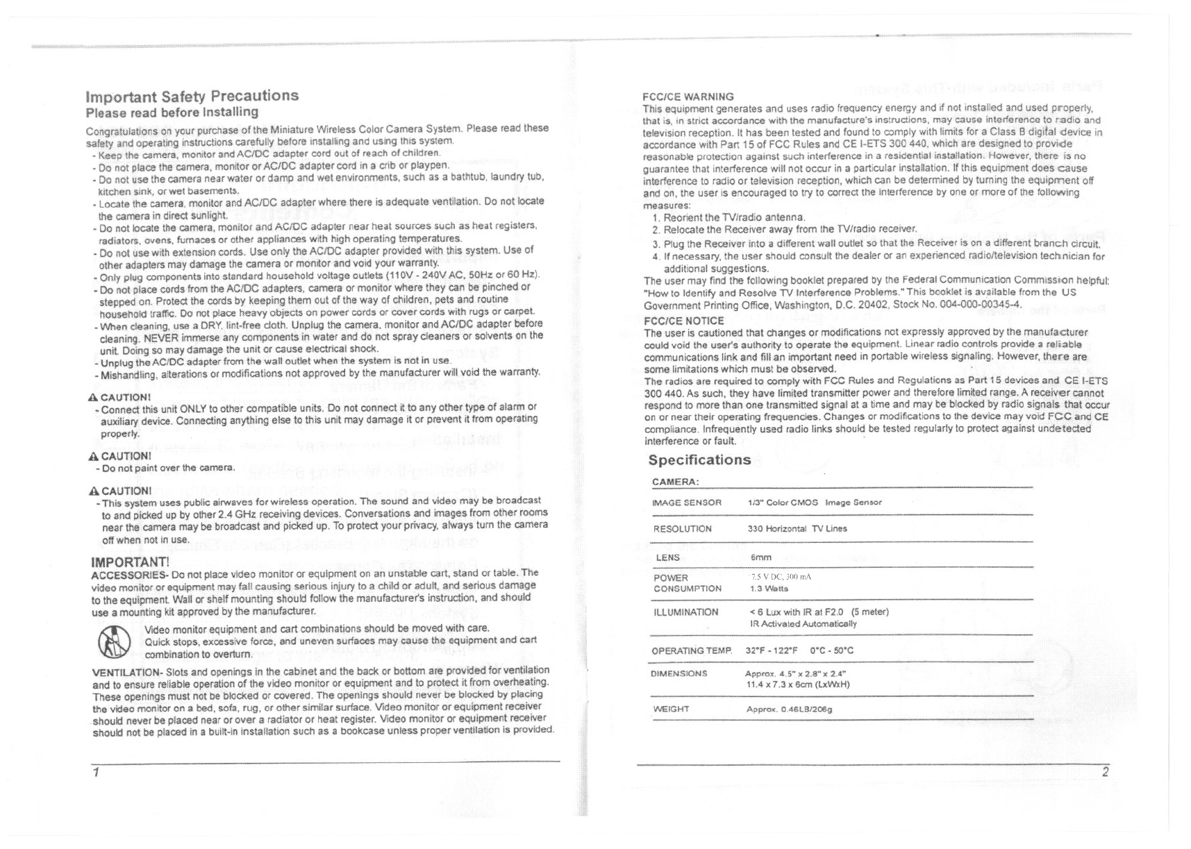
Specifications
the manufacturer
a reliable
there are
CE
IMAGE SENSOR 113" CoiorCMOS Il'Ntge Sensor
RESOLUTrON 330 Homontal TV Une~
LENS 6mm
POWER
CONSUMPTION
1.5 V DC, 300 mA
1 ,:) V\lall$
ILLUMINATION < 6 lllX with IR al F2,O meter)
OPERATING TEMP. 32"F . 122"F O'C - SO'C
DIMENSIONS Approx. 4,5-" 2.a- x 2,4"
HAy;. 1,3 x Gem (l.xWxH)
WEiGHT Appro", OA6LBJ200g
Pans Included with This System
-Camera with Built-In Transmitter
- 2.4 GI-btAudioNldeo Receiver
-12V ACJDC Adapter for the Receiver
- 1.5V300 RIA Adapter for the Camera
-1,5mAN ~ble
""
Parts of the Miniature Wireless Color Camera System
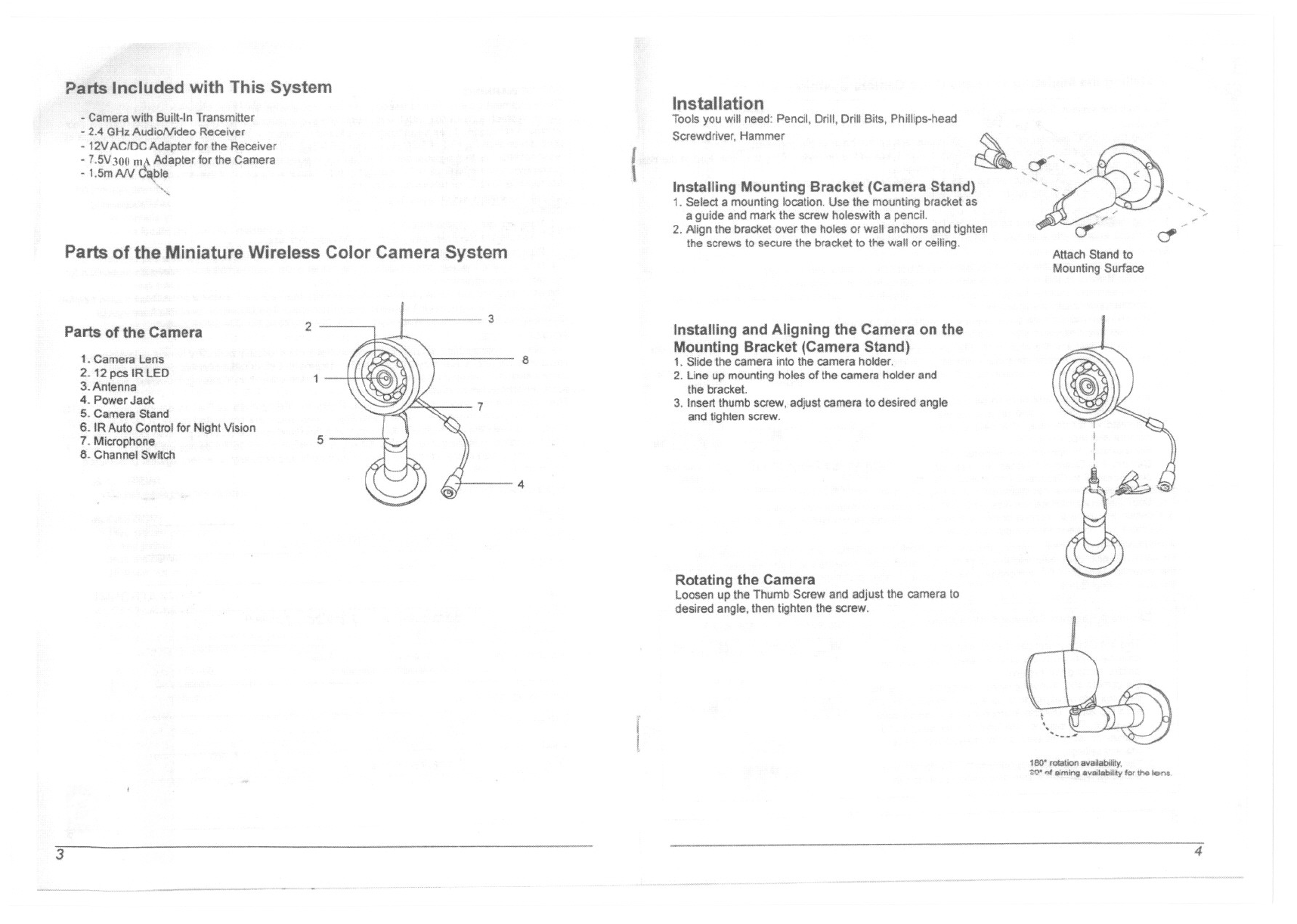
Parts of the Camera
1.Camers Lens
2. 12 p<:$IR LED
3.Antenna
4. PowerJack
5. Camera Stand
6. IR Auto Control for Night Vision
7. Mlcrophf)ne
8. Channel Switch
2
5
3
8
7
4
Installation
Toolsyou will need: Pencil,Drill, Drill Bits, Phillips.head
Screwdriver. Hammer
{Installing Mounting Bracket (Camera Stand)
1. Select a mounting location. Use the mounting bracket as
a guide and mark the screw holeswith a pencil.
2. Align the bracket over the holes or wall anchors and tighten
the screws to secure the bracket to the wall or ceiUng.
Installing and Aligning the Camera on the
Mounting Bracket (Camera Stand)
1. Slide the camera into the camera holder,
2. Lineup mountingholesof the camera holderand
the bracket.
3. Insertthumb screw,adjust camera10desired angle
and tighten screw.
Rotating the Camera
Loosen up the Thumb Screw and adjust the camera 10
desired angle. then lighten the screw.
,cr
~
."""'-"
.
'/'
"..,
'
,
'.' <
,.""-
,-
.,/
if ~
Attach Stand to
Mounting Surface
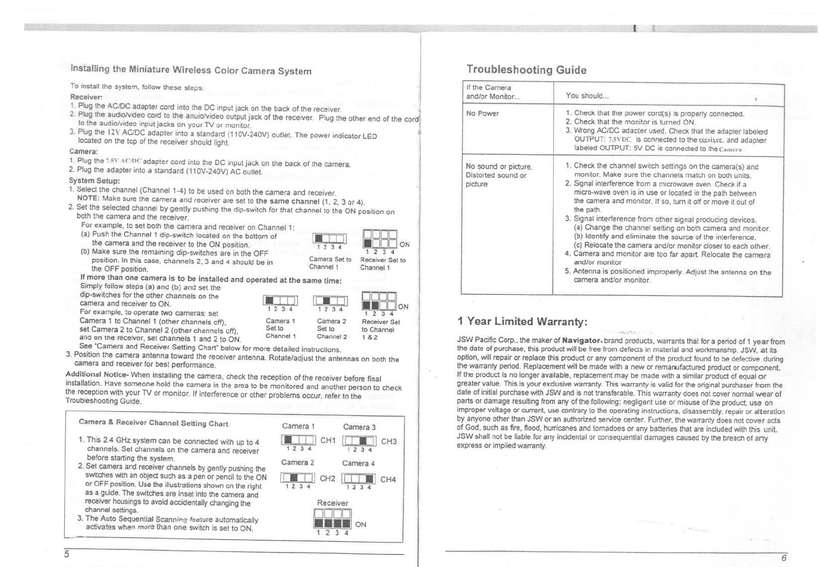
Installing the Miniature Wireless Color Camera System
Toinstallthe system, follow these steps:
Receiver:
1. Plug the AC/DC adapter cord into the DC input jack on the back ofthe receiver.
2. Plug the audlolvldeo cord to the anulo!v1deo output jack of the receiver. Plug the other end of the
to the audiolv1deo input jacks on your TV or monitor.
3. Plugthe nv ACIDC adapter Inlo a(110V-.240V) outlet The power indicator LED
located on the top of the reoelver
Camera:
1. Plug the 7.5VAcmc adapter cord into Ihe DC input jack on the back of the camera.
2. Plug the adapter inlo a standard (110V-240V) AC outlet
System Setup:
1.Selectthe channel(Channel1'-4) 10 be used onboththe cameraand receiver.
NOTE: Make sure the camera and receiver are set to the same channel (1, 2,3 or 4).
2. Set the selected channel by gently pushing the dip-switch for that channel 10the ON position on
both the camera and the receiver.
For example, to set both the camera and receiver on 1:
(a) Push the Channel 1 dip-switch located on the bottom l.'1]
the camera and the receiver to the ON position. 1 ;1 34
(b) Make sure the remaining dip-switches are In the OFF Carn Set 10
position. In this case, channels 2, 3 and 4 should be In Chan~:'1
the OFF position.
Ifmore than one camera is to be installed and operated at the same time:
Simply follow steps (a) and (b) and set the
dip-switches for the other channels on the
camera and receiver to ON.
For example, to operate two cameras: set
Camera 1 to Channel 1 (other channels off) Camera1 Camera2
, Set to Set to
setCamera 2 to Channel 2 (other channels off), Channel 1 Channa! 2
£1110on the rflceiller, set channels 1 and2 to ON.
See "Camera and Receiver Selting Chart" below for more detailed Instructions.
3. Position the camera antenna toward the receiver antenna. Rotate/adjust the antennas on both the
camera and receiver for best performance.
Additional Notice- When installing the camera, check the reception of the receiver before final
installation. Have someone hold the camera in the area to be monitored and another person to check
the receptionWithyourTV or monitor. If interferenceor other problemsC)CCUr,refer to the
Troubleshooting Guide.
1.-. i III
1;13 .. ['jJ III
1 2 3 4 1 ;1 :I 4
ReceiverSet
to Channel
1&2
Camera & Receiver Channel Setting Chart
1. This 2,4 GHz system can be connected with up to "
channels. Set channels on the camera and receiver
before starting the system.
2. Set camera and receiver channels by gently pushing the
switches Withan object such as a pen ar pencil to the ON
or OFF position. Use the illustrations shown on !he right
as a guide. The switches are inset into the camera and
receiver housings to avoid accidentally changing the
channel settings.
3. The Auto Sequential Scann."!; foOllure automatically
activates when more than one switch is set to' ON.
Camera 1 Camera3
CH1 Ii ! Iii 11CH3
12 3 4
Camera 2 Camera 4
1/:.i,H CH2 II I I -, CH4
1234 1234
Receiver
ON
Troubleshooting Guide
ON
1 Year Limited Warranty:
JSN'oIPacific Corp., !he meker of Navigator. brand products, warrants that for a pariodof 1 year from
the date of purchase, this product will be free from defects in material and workmanship. JSW, at its
option, will repair or replace this product or any component of the product found to be defective during
the warranty period. Replacement will be made with a new or remanufactured product or component.
If the product is no longer available,replacemern may be made with a similar product of equal or
greater value. This is your exclusive warranty. This warranty is valid for the original purchaser from the
date of initial purchase With JSW and is not transferable. This warranty does not cover norma! wear of
parts or damage resulting from any of the following: negligent use or misuse of the product, use on
improper voltage or current, use contrary to the operating instructions, disassembly, repair or alteration
by anyone other than JSW or an authorized service center. Further, the warranty does not cover ac!$
of God, such as lire, 110od, hurricanes and tomadoes or any batteries that are induded withthis unit
JSW shall not be liable for any incidental or consequential damages caused by the breach of any
express or implied warranty.
If the Camera
and/or Manitor... IYou should... i
No Power 1. Check that the power cord(s) Is properly connected.
2, Checkthatthe monitar is turned ON.
3. Wrong ACIDC adaotar used. Check Ihat the adapter labeled
OUTPUT: 7.5Vt)C. is connected 10the w;I\:fL. and adapter
labeled OUTPUT:'51/DC is connected to thecamcrn
No sound or picture. 1. Check the channel switch settings on the camera(s) and
Distorted sound or monitor. Make sure the channels match on both units.
picture 2. SIgnal interference from a microwave oven. Check if a
micro-wave oven is in use Orlocated in the path between
the camera and monitor. If so, tum it off or move it aut of
the path.
3. Signal interference from other signal producing devices.
(a) Change the channel setllng on both camera and monitor.
(b) Identify and eliminate the source of the inlerference.
(0) Relocate the camera and/or monitor closer 10 eacholher.
4. Camera and monitor are too far apart. Relacate the camera
and/or monitor
5. Antennais positioned improperly. Adjust the antenna on the
camera and/of monitor.
Federal Communication Commission Interference Statement
This equipment has been tested and found to comply with the limits for a Class B digital device, pursuant to Part
15 of the FCC Rules. These limits are designed to provide reasonable protection against harmful interference in
a residential installation.
This equipment generates, uses and can radiate radio frequency energy and, if not installed and used in
accordance with the instructions, may cause harmful interference to radio communications. However, there is no
guarantee that interference will not occur in a particular installation. If this equipment does cause harmful
interference to radio or television reception, which can be determined by turning the equipment off and on, the
user is encouraged to try to correct the interference by one of the following measures:
. Reorient or relocate the receiving antenna.
. Increase the separation between the equipment and receiver.
. Connect the equipment into an outlet on a circuit different from that to which the receiver is connected.
. Consult the dealer or an experienced radio/TV technician for help.
FCC Caution : To assure continued compliance, any changes or modifications not expressly approved by the party
responsible for compliance could void the user's authority to operate this equipment. (Example - use only shielded interface
cables when connecting to computer or peripheral devices).
This device complies with Part 15 of the FCC Rules. Operation is subject to the following two conditions:
(1) This device may not cause harmful interference, and (2) This device must accept any interference received,
including interference that may cause undesired operation
.