JSW Pacific MSTR51 Smart wireless central home control / management center User Manual QSG SHC draft
JSW Pacific Corporation Smart wireless central home control / management center QSG SHC draft
User manual
QUICK START GUIDE
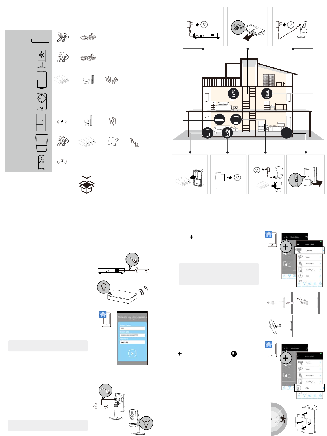
KIT CONTENT
SYSTEM INTRODUCTION
GETTING STARTED
1. Connect the gateway box to the Internet
(1) Connect gateway box to your router via the Ethernet
cable. Then plug in the supplied power cable.
(2) The power LED indicator becomes steady RED and
you will hear the gateway box beep twice. This
means the gateway box is ready for APP setup.
(3) Launch 'OMGUARD SHC' APP. The APP will
automatically search the available gateway box and
brings up the system DID/password. If it is not
shown, Please check the system DID on the bottom
of the gateway box. Enter the system DID and default
password 123456 manually.
Note: The gateway box should be powered on and
connected to the Internet at all times.
You can continue to setup the camera and sensor(s) now.
2. Set up the IP Camera
(1) Connect the IP Camera to your router via the
Ethernet cable .
(2) Plug in the power adapter and wait until both RED
and GREED LED begin ashing.
Note: DO NOT begin the APP setup process until both
LEDs become steady on.
Adaptor DC12V/1A
Adaptor DC12V/1A
Adaptor DC12V/1A
Adaptor DC12V/1A
Ethernet cable 2M
Battery AA 1.5V
Battery AA 1.5V x 3
NA
Sticky pad Screw
Battery CR2032 Sticky pad
Adaptor DC 5V/1 A Battery AA 1.5V
or Battery AA 1.5V x 4
Bracket
x 1
Adaptor DC 5V/1.5A
x 1
x 1
x 3 x 4 x 4
x 1 x 3 x 4
x 1 x 4 x 1
Battery CR2032
x 1
Screw
x 2
Screw
Gayway
IP Camera
Motion PIR
On / O Switch
Door / Window
Sensor
Indoor Siren
Panic Remote
Steady RED
(3) Launch the 'OMGUARD SHC' APP. Click the 'ADD'
icon and choose 'Camera' to add the device to
system.
Follow the APP wizard setup process to add the
camera.
Note: The APP will search the available IP Camera in
LAN area. If the camera you're setting doesn't
appear in the searching list, please enter the
camera ID (DID) and password manually.
Installing the IP Camera:
(1) Secure the camera stand on the stable surface.
(2) Mount the camera into camera stand. Adjust the
viewing angle and x the camera tightly.
3. Pair the Motion Sensor
Launch the 'OMGUARD SHC' APP. Click the 'ADD' icon
and choose 'Motion Sensor' and to initiate the
pairing process, following with pressing the pairing
button located inside the battery compartment to
complete the process.
Installing the Motion Sensor:
(1) Place the motion sensor upward, facing the location
to be monitored. The detection distance is up to 16
meteres.
For maximum coverage, it is recommanded to place
the motion sensor highup with its back against the
corner of walls to ensure best detection coverage.
(2) Use the double-sided tape to x the motion sensor.
OMGUARDSHC
OMGUARDSHC
OMGUARDSHC
Ethernet cable 2M
x 1
Gateway
Smart wireless central home
control / management center.
Serie No.
Door / Window Sensor
Wireless door / window access
alert sensor.
Indoor Siren
Wireless portable / wall-
mount alert siren.
Panic Remote
Wireless multi-functional panic
remote controller.
IP Camera
Wireless day / night portable
motion alert indoor camera.
Motion PIR
Wireless portable / wall-
mount area motion alert
sensor.
On / O Switch
Wireless appliance energy
management power switch /
signal repeater (single device)
Remove the insulating plastic
Remove the insulating plastic
16 meters
?
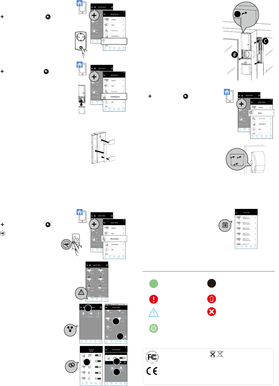
4. Pairing the Power Switch
Launch the 'OMGUARD SHC' APP. Click the 'ADD' icon
and choose ‘Power Switch' and to initiate the
pairing process, following with press/hold the front
panel button until LED ashing blue.
To initiate the repeater function, press / hold the front
panel button turned orange, following with pressing the
pairing button on the device .
5. Pairing the Door / Window Sensor
Launch the 'OMGUARD SHC' APP. Click the 'ADD' icon
and choose 'Door Sensor' and to initiate the
pairing process, following with removing and reinstalling
the battery compartment cover to complete the process.
Installing the Door/Window Sensor
Using the double-sided tape:
(1) Apply the double-sided tape to the backs of the
Door/Window sensor.
(2) Select a location on the door/window. The large
piece of the sensor should be xed on the immovable
frame of the door/window.
Align the small piece to the large one. Fix the small
piece on the movable part of the door/window
frame.
(3) When it is nished, open the door or window to test
if the sensor has been correctly installed. You'll
receive an alert from the mobile device if the APP and
sensor have been corrected installed.
FCC Compliance Statement: This device complies with Part 15 of the
FCC rules. Operation is subjected to the following two conditions:
(1)this device may not cause harmful interference, and (2) this device
must accept any interferencereceived, including interference that
may cause undesired operation.
Products with CE Marking comply with EMC Directive (2004/108/EC);
Low Voltage Directive (73/23/EEC); R&TTE (1999/5/EC); ROHS Directive
(2011/65/EU) issued by the Commission of the European Community.
Compliance with these directives implies conformity to the following
European Norms:
EMC: EN 301 489
LVD: EN 60950
Radio: EN 300 328
If the camera system no longer functions or can no longer be repaired,
it must be disposed of according to the valid statutory regulations.
Disposal of spent batteries/accumulators:
You are required by law (Battery Ordinance) to return all spent batteries and
accumulators. Disposing of spent batteries/accumulators with common household waste
is prohibited! Batteries/accumulators that contain hazardous substances are marked
with the symbols on the side. These symbols indicate that it is prohibited to dispose of
these batteries/accumulators in the household waste. The abbreviations for the respective
heavy metals are: Cd=cadmium, Hg=mercury, Pb=lead. You can return spent batteries
and accumulators that can no longer be charged to the designated collection points in
your community, outlets or wherever batteries or accumulators are sold. Following these
instructions will allow you to fulll the legal requirements and contribute to the protection
of our environment!
Using the mounting screws:
(1) Fix the rst mounting screw directly onto the door /
window frame (A). Place (hang) the larger piece on
to the mounted screw, remove the battery compart
ment cover to x the second mounting screw (B).
(2) Open back cover of the small piece. Use the
mounting screws to x the back cover on the
movable part of the door/window frame (C).
Mount the senor onto the back cover.
(3) When it is nished, open the door or window to test
if the sensor has been correctly installed. You'll
receive an alert from the mobile device if the APP and
sensor have been corrected installed.
6. Indoor Siren
Launch the 'OMGUARD SHC' APP. Click the 'ADD' icon
and choose 'Siren' and to initiate the pairing
process, following with pressing the pairing button
inside the battery compartment to complete the
process.
Installing the Siren:
It is recommanded to install (wall-mount / place on at
surface) the Siren in a highly visible location with
minimum obsticles near for maximum visual and sound
alert deterrence in critical situations. A/C power option
is available, choose a suitable power outlet location for
the installation.
7. Pairing the Remote Control
Launch the 'OMGUARD SHC' APP. Click the 'ADD' icon
and choose 'Panic Remote' and to initiate the
pairing process, following with press/hold the camera
button until the LED ashing blue.
8. APP Operation
Display device status in realtime. Tap "Status" to refresh
the status page.
Setup groups of devices for instant function activation /
deactivation.
1. Choose "+" to start a new "control".
2. Naming the control and select device(s).
3. Save.
Setup various scenarios for system to launch pre-
congured settings governing the behaviour of lights,
cameras and sirens.
1. Choose a device (initiator) from the list.
2. Choose "+" to add additional device (follower). Repeat
to add additional device(s).
3. Save.
Example: "Motion PIR" (initator) > "Power Switch"
(follower) > "Save".
OMGUARDSHC
OMGUARDSHC
OMGUARDSHC
OMGUARDSHC
Slot
Status
Scenario
Events
Group
1
1
2
2
3
3
A
B
C
List of triggered events from device(s) and playback from
camera(s).
STATUS INDICATOR
ON OFF
Sensor On
Sensor Triggered
Vandal Alert
Edit Mode
Sensor O
Power Low
Delete
FCC Compliance Statement: This device complies with Part 15 of the FCC rules. Operation is
subjected to the following two conditions: (1) this device may not cause harmful interference, and
(2) this device must accept any interference received, including interference that may cause
undesired operation.
This device complies with Industry Canada’s licence-exempt RSSs.Operation is subject to the
following two conditions: (1) this device may not cause interference, and (2) this device must
accept any interference, including interference that may cause undesired operation of the device.
Cet appareil est conforme aux CNR exemptes de licence d'Industrie Canada . Son fonctionnement
est soumis aux deux conditions suivantes :
( 1 ) Ce dispositif ne peut causer d'interférences ; et
( 2 ) Ce dispositif doit accepter toute interférence , y compris les interférences qui peuvent causer
un mauvais fonctionnement de l'appareil.
Changes or modifications not expressly approved by the party responsible for compliance could
void your authority to operate the equipment.