JSW Pacific SAV-2450 Wireless Dual-Mode Color Camera Kit User Manual
JSW Pacific Corporation Wireless Dual-Mode Color Camera Kit Users Manual
Users Manual
- - - -
I
-------- -[ I
t
"Navigator"
User's Manual
Model No.: SAV-2450
Walkie- Watchie
Wireless Dual-Mode Color Camera Kit
.
- 2.4GHz Wireless Receiver with Rod Antenna
- Wireless PIT Color Camera
!I
)\
f\
f
00
"""'u
aaa~
Q)
~--- .
aa
a.O 0
. 0°
O~ooo 0
PLEASE READ CAREFULLYAND SAVE
This manual contains important information about this product's operation.
If you are installing this product for use by others you must leave this
manual -or a copy- with the end user.
Federal Communication Commission Interference Statement
This equipment has been tested and found to comply with the limits for a Class B digital device,
pursuant to Part 15 of the FCC Rules. These limits are designed to provide reasonable protection
against harmful interference in a residential installation.
This equipment generates, uses and can radiate radio frequency energy and, if not installed and
used in accordance with the instructions, may cause harmful interference to radio communications.
However, there is no guarantee that interference will not occur in a particular installation. If this
equipment does cause harmful interference to radio or television reception, which can be determined
by turning the equipment off and on, the user is encouraged to try to correct the interference by one
of the following measures:
. Reorient or relocate the receiving antenna.
. Increase the separation between the equipment and receiver.
. Connect the equipment into an outlet on a circuit different from that to which the receiver is connected.
. Consult the dealer or an experienced radio/TV technician for help.
FCC Caution :To assure continued compliance, any changes or modifications not expressly approved
by the party responsible for compliance could void the user's authority to operate this equipment.
(Example - use only shielded interface cables when connecting to computer or peripheral devices).
This device complies with Part 15 of the FCC Rules. Operation is subject to the following
two conditions:
(1) This device may not cause harmful interference, and
(2) This device must accept any interference received, including interference
that may cause undesired operation.
-= ----I
Model No.: SAV-2450
,
Walkie-Watchie Wireless Dual-Mode Color Camera Kit
Important!
Please read this booklet carefully
before installing or using these units.
DANGER- HIGH VOLTAGE- These units
should ONLY be opened by an authorized
technician if service is required.
Contents
Safety Precautions
For correct and safe operation of this
system, it is essential that installers, end-
users and service technicians should follow
all safety procedures outlineq in this
manual. Specific Warning and Caution
statements (and/or symbols) are marked on
the units where needed.
Warning and Caution Statements
"WARNING" indicates a situation where
failure to follow proper procedures can
cause personal injury.
"CAUTION" indicates a situation where
failure to follow proper procedures can
cause damage to the equipment.
Important Safety Precautions 1
Specifications ... : 2
Parts Included with This System , 3
Parts of Wireless Dual-Mode Color Camera Kit 3
- Parts of the Receiver 3
- Parts ofthe Comera 4
Installation ... 4
-Installing Camera Mounting Bracket
for wall mounting 4
-Installing Wireless Dual-mode Color Camera Kit S
Troubleshooting Guide 6
Warranty 6
Important Safety Precautions
Please read before Installing
Congratulations on your purchase of the Walkie-watchie Wireless Dual-Mode Color Camera Kit.
Please read these safety and operating instructions carefully before installing and using this system.
- Keep the camera, monitor and ACIDC adapter cord out of reach of children.
- Do not place the camera, monitor or ACIDC adapter cord in a crib or playpen.
- Do not use the camera near water or damp and wet environments, such as a bathtub, laundry tub,
kitchen sink, or wet basements.
- Locate the camera, monitor and ACIDC adapter where there is adequate ventilation. Do not locate
the camera in direct sunlight.
- Do not locate the camera, monitor and AC/DC adapter near heat sources such as heat registers,
radiators, ovens, furnaces or other appliances with high operating temperatures.
- Do not use with extension cords. Use only the ACIDC adapter provided with this system. Use of
other adapters may damage the camera or monitor and void your warranty.
- Only plug components into standard household voltage outlets (110V -240V AC, 50Hz or 60 Hz).
- Do not place cords from the ACIDC adapters, camera or monitor where they can be pinched or
stepped on. Protect the cords by keeping them out of the way of children, pets and routine
household traffic. Do not place heavy objects on power cords or cover cords with rugs or carpet.
- When cleaning, use a DRY, lint-free cloth. Unplug the camera, monitor and ACIDC adapter before
cleaning. NEVER immerse any components in water and do not spray cleaners or solvents on the
unit. Doing so may damage the unit or cause electrical shock.
- Unplug the ACIDC adapter from the wall outlet when the system is not in use.
- Mishandling, alterations or modifications not approved by the manufacturer will void the warranty.
A CAUTION!
- Connect this unit ONLY to other compatible units. Do not connect it to any other type of alarm or
auxiliary device. Connecting anything else to this unit may damage it or prevent it from operating
properly. .
A CAUTION!
-Do not paint over the camera.
A CAUTIONI
- This system uses public airwaves for wireless operation. The sound and video may be broadcast
to and picked up by other 2.4 GHz receiving devices. Conversations and images from other rooms
near the camera may be broadcast and picked up. To protect your privacy, always turn the camera
off when not in use.
FCC/CE WARNING
This equipment generates and uses radio frequency energy and if not installed and used properly,
that is, in strict accordance with the manufacture's instructions, may cause interference to radio and
television reception. It has been tested and found to comply with limits for a Class 8 digital device in
accordance with Part 15 of FCC Rules and CE I-ETS 300 440, which are designed to provide
reasonable protection against such interference in a residential installation. However, there is no
guarantee that interference will not occur in a particular installation. If this equipment does cause
interference to radio or television reception, which can be determined by turning the equipment off
and on, the user is encouraged to try to correct the interference by one or more of the following
measures:
1. Reorient the TV/radio antenna.
2. Relocate the Receiver away from the TV/radio receiver.
3. Plug the Receiver into a different wall outlet so that the Receiver is on a different branch circuit.
4. If necessary, the user should consult the dealer or an experienced radio/television technician for
additional suggestions.
The user may find the following booklet prepared by the Federal Communication Commission helpful:
"How to Identify and Resolve TV Interference Problems." This booklet is available from the US
Government Printing Office, Washington, D.C. 20402, Stock No. 004-000-00345-4.
FCC/CE NOTICE
The user is cautioned that changes or modifications not expressly approved by the manufacturer
could void the user's authority to operate the equipment. Linear radio controls provide a reliable
communications link and fill an important need in portable wireless signaling. However, there are
some limitations which must be observed.
The radios are required to comply with FCC Rules and Regulations as Part 15 devices and CE I-ETS
300 440. As such, they have limited transmitter power and therefore limited range. A receiver cannot
respond to more than one transmitted signal at a time and may be blocked by radio signals that occur.
on or near their operating frequencies. Changes or modifications to the device may void FCC and CE
compliance. Infrequently used radio links should be tested regularly to protect against undetected
interference or fault.
IMPORTANT! .
ACCESSORIES- Do not place video monitor or equipment on an unstable cart, stand or table. The
video monitor or equipment may fall causing serious injury to a child or adult, and serious damage
to the equipment. Wall or shelf mounting should follow the manufacturer's instruction, and should
use a mounting kit approved by the manufacturer.
~Video monitor equipment and cart combinations should be moved with care.
'W Quick stops, excessive force, and uneven surfaces may cause the equipment and cart
combination to overturn.
VENTILATION- Slots and openings in the cabinet and the back or bottom are provided for ventilation
and to ensure reliable operation of the video monitor or equipment and to protect it from overheating.
These openings must not be blocked or covered. The openings should never be blocked by placing
the video monitor on a bed, sofa, rug, or other similar surface. Video monitor or equipment receiver
should never be placed near or over a radiator or heat register. Video monitor or equipment receiver
should not be placed in a built-in installation such as a bookcase unless proper ventilation is provided.
DIMENSIONS Approx.
12 x 8 x 4cm (LxWxH)
WEIGHT Approx.157g
12
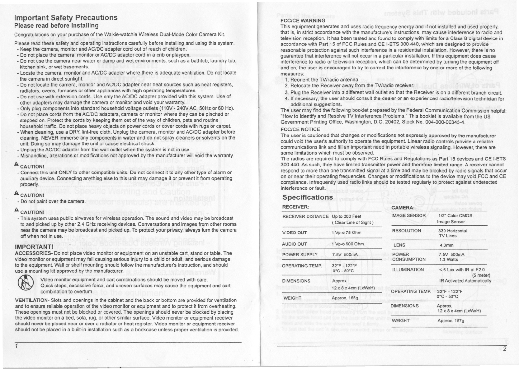
Specifications
RECEIVER: CAMERA:
RECEIVERDISTANCE Up to 300 Feet IMAGE SENSOR 113"Color CMOS
( Clear Line of Sight) Image Sensor
VIDEO OUT 1 Vp-o 75 Ohm RESOLUTION 330 Horizontal
TV Lines
AUDIO OUT 1 Vp-o 600 Ohm lENS 4.3mm
POWER SUPPLY 7.5V 500mA POWER 7.5V 500mA
CONSUMPTION 1.3 Watts
OPERATING TEMP. 32°F - 122°F
O°C- 50°C IllUMINATION < 6 lux with IR at F2.0
(5 meter)
DIMENSIONS Approx. IRActivated Automatically
12 x 8 x 4cm (LxWxH) OPERATING TEMP. 32°F -122°F
WEIGHT Approx.165g O°C-50°C
Parts Included with This System
- PIT Camera with Built-In Transmitter
- 2.4 GHz AudioNideo Receiver
- 7.5V 500mA Adapter for the Receiver
- 7.5V 500mAAdapter for the Camera
-AN Cable
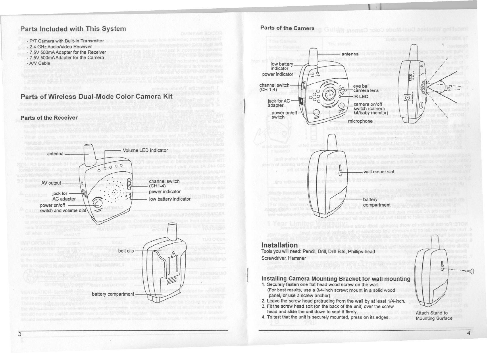
Parts of Wireless Dual-Mode Color Camera Kit
Parts of the Receiver
antenna
AVoutput
jack for
AC adapter
power on/off -
switch and volume dial
Volume LED Indicator
belt clip
battery compartment
channel switch
(CH1-4)
power indicator
low battery indicator
3
c::I J
Parts of the Camera
low battery
indicator
power indicator
channel switch
(CH 1-4)
}
jack for AC
adapter
power on/off
switch
antenna
eye ball
camera lens
IRLED
camera on/off
switch (camera
kiUbaby monitor)
microphone
wall mount slot
battery
compartment
Installation
Tools you will need: Pencil, Drill, Drill Bits, Phillips-head
Screwdriver, Hammer
(Installing Camera Mounting Bracket for wall mounting
1. Securely fasten one flat head wood screw on the wall.
(For best results, use a 3/4-inch screw; mount in a solid wood
panel, or use a screw anchor).
2. Leave the screw head protruding from the wall by at least 1/4-inch.
3. Fit the screw head salt (on the back of the unit) over the screw
head and slide the unit down to seat it firmly.
4. To test that the unit is securely mounted, press on its edges. Attach Stand to
Mounting Surface
4
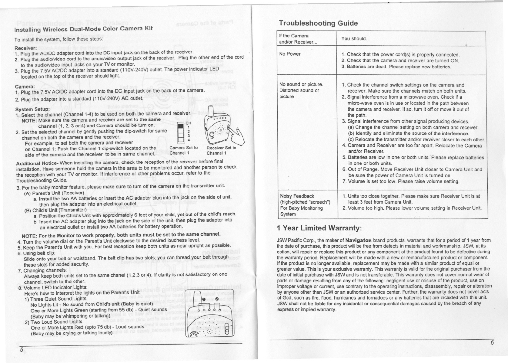
Installing Wireless Dual-Mode Color Camera Kit
To install the system, follow these steps:
Troubleshooting Guide
~'f
Receiver:
1. Plug the AC/DC adapter cord into the DC input jack on the back of the receiver.
2. Plug the audio/video cord to the anuio/video output jack of the receiver. Plug the other end of the cord
to the audiolvideo input jacks on your 1V or monitor.
3. Plug the 7.5V ACIDC adapter into a standard (11OV-240V) outlet. The power indicator LED
located on the top of the receiver should light.
Camera:
1. Plug the 7.5V ACIDC adapter cord into the DC input jack on the back of the camera.
2. Plug the adapter into a standard (110V-240V) AC outlet.
System Setup:
1. Select the channel (ChanneI1-4) to be used on both the camera and receiver.
NOTE: Make sure the camera and receiver are set to the same I
channel (1, 2, 3 or 4) and Camera should be turn on.
2. Set the selected channel by gently pushing the dip-switch for same
channel on both the camera and the receiver.
For example, to set both the camera and receiver
on Channel 1: Push the Channel 1 dip-switch located on the Camera Set to Receiver Set to
side of the camera and the receiver to be in same channel. Channel 1 Channel 1
Additional Notice- When installing the camera, check the reception of the receiver before final
installation. Have someone hold the camera in the area to be monitored and another person to check
the reception with your TV or monitor. If interference or other problems occur, refer to the
Troubleshooting Guide.
3. For the baby monitor feature, please make sure to turn off the camera on the transmitter unit.
(A) Parent's Unit (Receiver)
a. Install the two AA batteries or insert the AC adapter plug into the jack on the side of unit,
then plug the adapter into an electrical outlet.
(B) Child's Unit (Transmitter)
a. Position the Child's Unit with approximately 6 feet of your child, yet out of the child's reach.
b. Insert the AC adapter plug into the jack on the side of the unit, then plug the adaptor into
an electrical outlet or install two AA batteries for battery operation.
NOTE: For the Monitor to work properly, both units must be set to the same channel.
4. Turn the volume dial on the Parent's Unit clockwise to the desired loudness level.
5. Keep the Parent's Unit with you. For best reception keep both units as near upright as possible.
6. Using belt clip:
Slide onto your belt or waistband. The belt clip has two slots; you can thread your belt through
these slots for added security.
7. Changing channels:
Always keep both units set to the same chanel (1,2,3 or 4). If clarity is not satisfactory on one
channel, switch to the other.
8. Volume LED Indicator Lights:
Here's how to interpret the lights on the Parent's Unit.
1} Three Quiet Sound Lights
No Lights Lit -No sound from Child's unit (Baby is quiet).
One or More Lights Green (starting from 55 db) -Quiet sounds
(Baby may be whimpering or talking).
2} Two Loud Sound Lights
One or More Lights Red (upto 75 db) -Loud sounds
(Baby may be crying or talking loudly).
5
1 Year Limited Warranty:
JSW Pacific Corp., the maker of Navigato. brand products, warrants that for a period of 1 year from
the date of purchase, this product will be free from defects in material and workmanship. JSW, at its
option, will repair or replace this product or any component of the product found to be defective during
the warranty period. Replacement will be made with a new or remanufactured product or component.
If the product is no longer available, replacement may be made with a similar product of equal or
greater value. This is your exclusive warranty. This warranty is valid for the original purchaser from the
date of initial purchase with JSW and is not transferable. This warranty does not cover nonnal wear of
parts or damage resulting from any of the following: negligent use or misuse of the product, use on
improper voltage or current, use contrary to the operating instructions, disassembly, repair or alteration
by anyone other than JSW or an authorized service center. Further, the warranty does not cover acts
of God, such as fire, flood, hurricanes and tornadoes or any batteries that are included with this unit.
JSW shall not be liable for any incidental or consequential damages caused by the breach of any
express or implied warranty.
6
If the Camera You should...
and/or Receiver... .
No Power 1. Check that the power cord(s) is properly connected.
2. Check that the camera and receiver are turned ON.
3. Batteries are dead. Please replace new batteries.
No sound or picture. 1. Check the channel switch settings on the camera and
Distorted sound or receiver. Make sure the channels match on both units.
picture 2. Signal interference from a microwave oven. Check if a
micro-wave oven is in use or located in the path between
the camera and receiver. If so, turn it off or move it out of
the path.
3. Signal interference from other slgnai producing devices.
(a) Change the channel setting on both camera and receiver.
(b) Identify and eliminate the source of the interference.
(c) Relocate the transmitter and/or receiver closer to each other.
4. Camera and Receiver are too far apart. Relocate the Camera
and/or Receiver.
5. Batteries are low in one or both units'-Please replace batteries
in one or both units.
6. Out of Range. Move Receiver Unit closer to Camera Unit and
be sure the power of Camera Unit is turned on.
7. Volume is set too low. Please raise volume setting.
Noisy Feedback 1. Units too close together. Please make sure Receiver Unit is at
(high-pitched "screech") least 3 feet from Camera Unit.
For Baby Monitoring 2. Volume too high. Please lower volume setting in Receiver Unit.
System