JVC KENWOOD 28451110 144/440MHz FM Dual Bander User Manual TM D700 E 00 Thank you
JVC KENWOOD Corporation 144/440MHz FM Dual Bander TM D700 E 00 Thank you
UserManual.wiki
>
JVC KENWOOD
>
28451110 User Manual
Users Manual
Navigation menu
Upload a User Manual
Namespaces
Wiki Guide
HTML
PDF
Info
Views
User Manual
Discussion / Help
Navigation
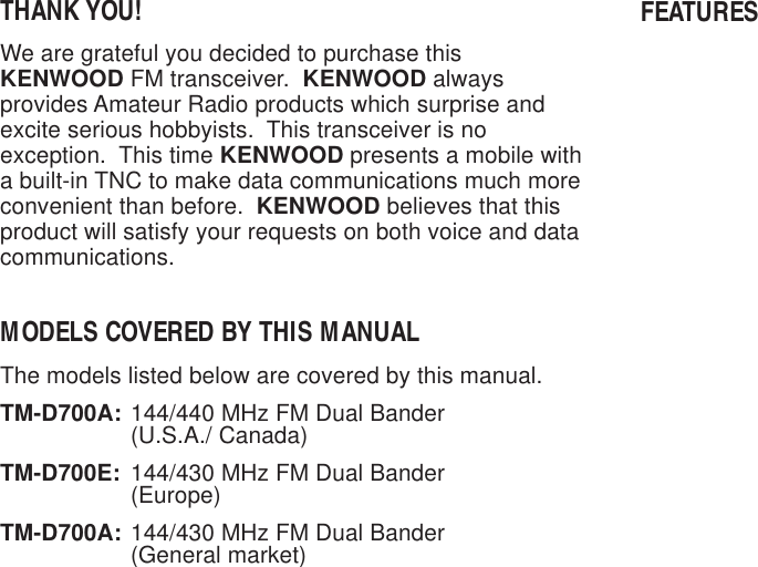
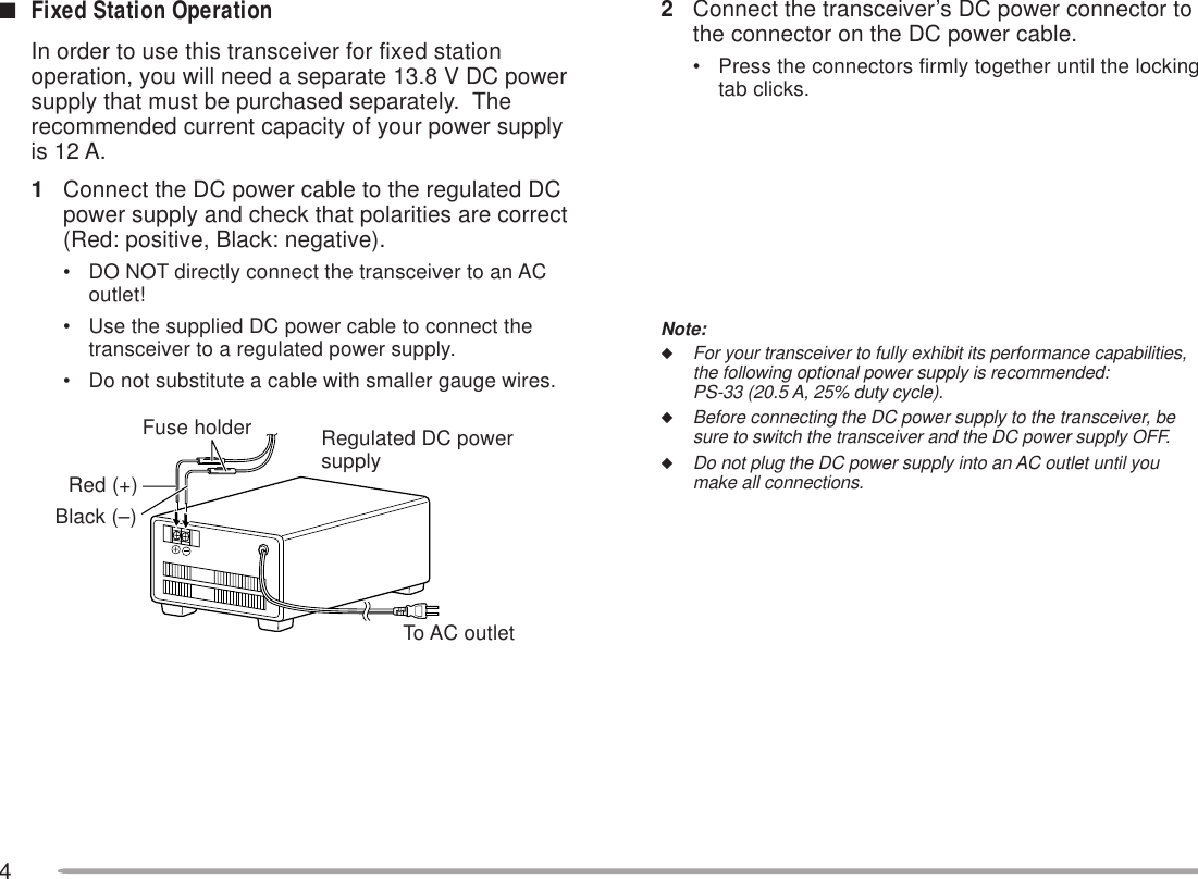
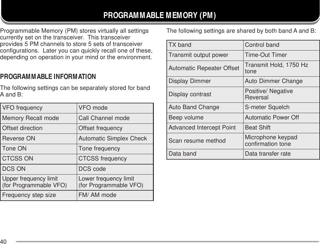
![1SUPPLIED ACCESSORIESA market code (K, E, or M4) can be found on the labelattached on the package box.1The screw set includes screws for attaching the microphonehanger {page XX}.2When using the transceiver as a fixed station, you may putthese cushions under the main unit to prevent it fromscratching the desktop.CONVENTIONS FOLLOWED IN THIS MANUALThe writing conventions described below have beenfollowed to simplify instructions and avoid unnecessaryrepetition.noitcurtsnI odottahWsserP ]YEK[ .esaelerdnasserP YEK .sserP )s1(]YEK[ .dlohdnasserP YEK rodnoces1rof.regnolsserP ]1YEK[ ,]2YEK[ .sserP 1YEK esaeler,yliratnemom1YEK sserpneht, 2YEK .sserP +]YEK[ NOREWOP .sserp,FFOrewopreviecsnarthtiW dlohdna YEK ehtNOnrutneht, gnisserpybrewopreviecsnart ]RWP[ .sserP )s1(]F[ ,]YEK[ .dlohdnasserP ]F[ rodnoces1rofsserpneht,regnol YEK .sserP ]F[ ,]YEK[)s1( .sserP ]F[ esaeler,yliratnemom ]F[ ,dlohdnasserpneht YEK 1rof.regnolrodnocessserP ]YEK[+]F[ .dlohdnasserP ]F[ sserpneht, YEK .yrosseccA rebmuNtraP ytitnauQenohporciM MD35-CM:K 54-CM:4M/E XX-6850-19T XX-6930-19T 11elbacrewopCDXX-1112-03E1)A51(esufreviecsnarTXX-7100-15F1tekcarbgnitnuomlenaptnorF )riapeno( XX-3660-92J XX-4660-92J 11tekcarbgnitnuomtinu-niaMXX-8260-92J1regnahenohporciM )ylnoK( XX-6251-91J1tinuniamrofteswercSK14M/E XX-2830-99N XX-1330-99N 11lenaptnorfrofteswercSXX-4102-99N1elbacgulpraludoMXX-1933-03E1noihsuC2XX-8840-20J4dracytnarraW )ylnoeporuE/adanaC/.A.S.U( —1launamnoitcurtsnI niaM snoitacinummoCdezilaicepS XX-8221-26B XXXXXX-26B 11](https://usermanual.wiki/JVC-KENWOOD/28451110/User-Guide-59321-Page-3.png)
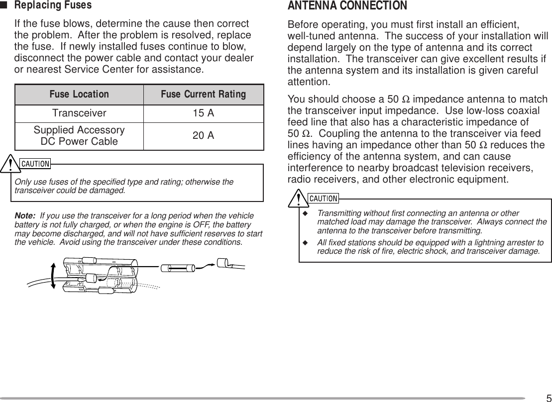
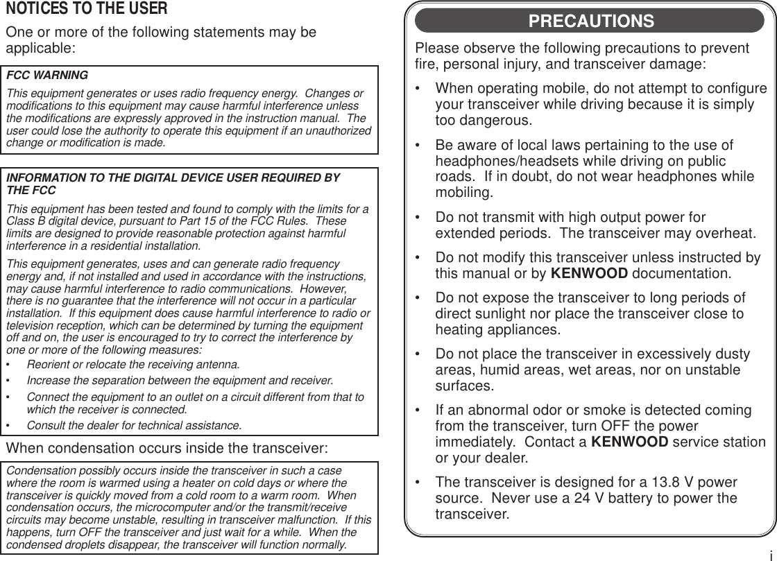
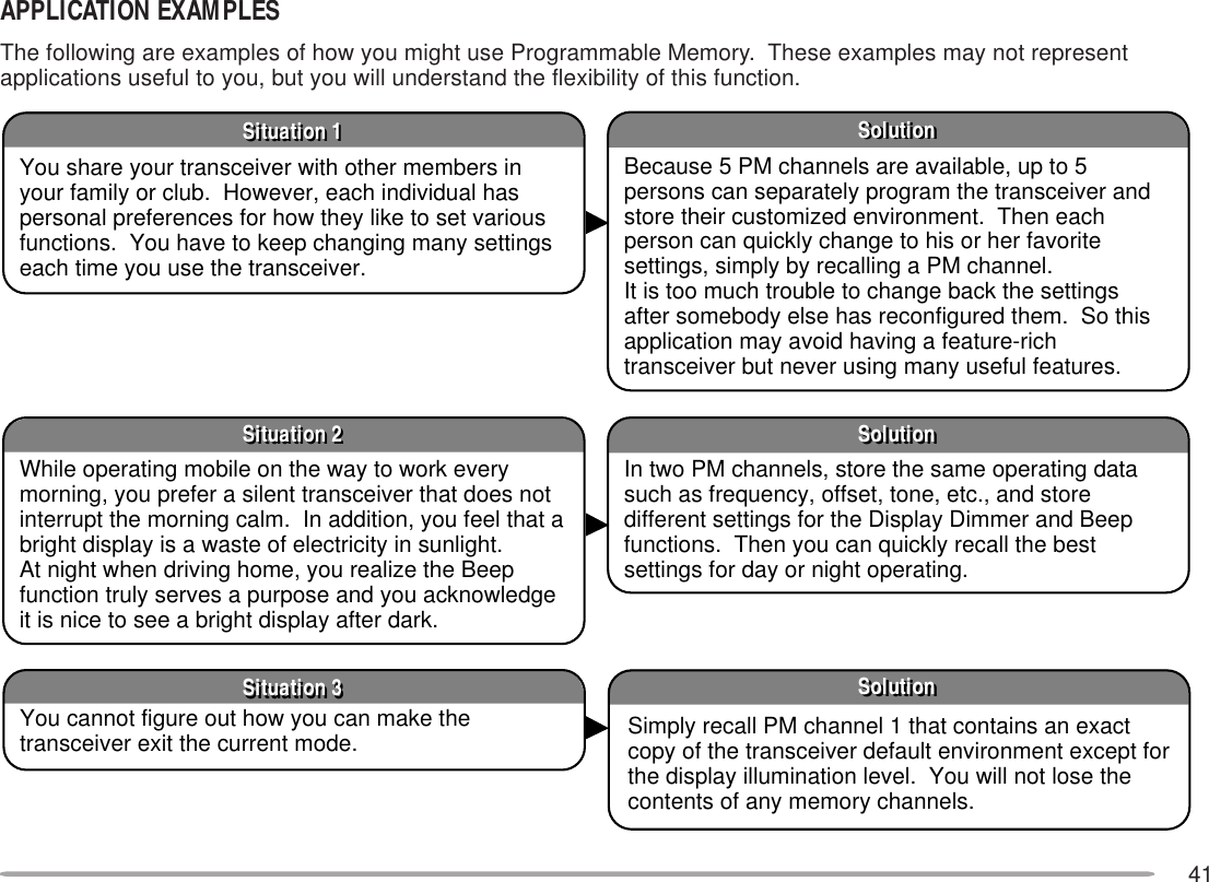
![7YOUR FIRST QSOIf you tend to discard instruction manuals along with thepackaging material .....please don’t. The 7 steps given here willget you on the air in your first QSO right away. So, you can enjoythe exhilaration that comes with opening a brand newtransceiver.After trying the rig for a while, settle back in your mostcomfortable operating chair with this manual and your favoritedrink for an hour or two. The time spent will be worthwhile.YOUR FIRST QSOSwitch ON the DC power supply, then press the PWR switch.Turn the VOL and SQL controls to approximately 9 o’clock.Press [BAND SEL] to select the VHF or UHF band.Turn the Tuning control to select a frequency.Press and hold Mic [PTT], then speak in a normal tone of voice.Release Mic [PTT] to receive.Repeat steps and to continue communication.](https://usermanual.wiki/JVC-KENWOOD/28451110/User-Guide-59321-Page-9.png)
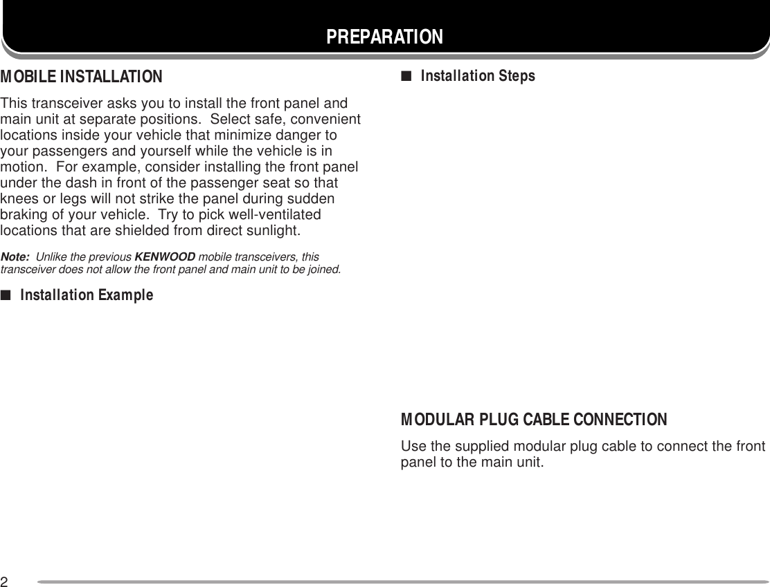
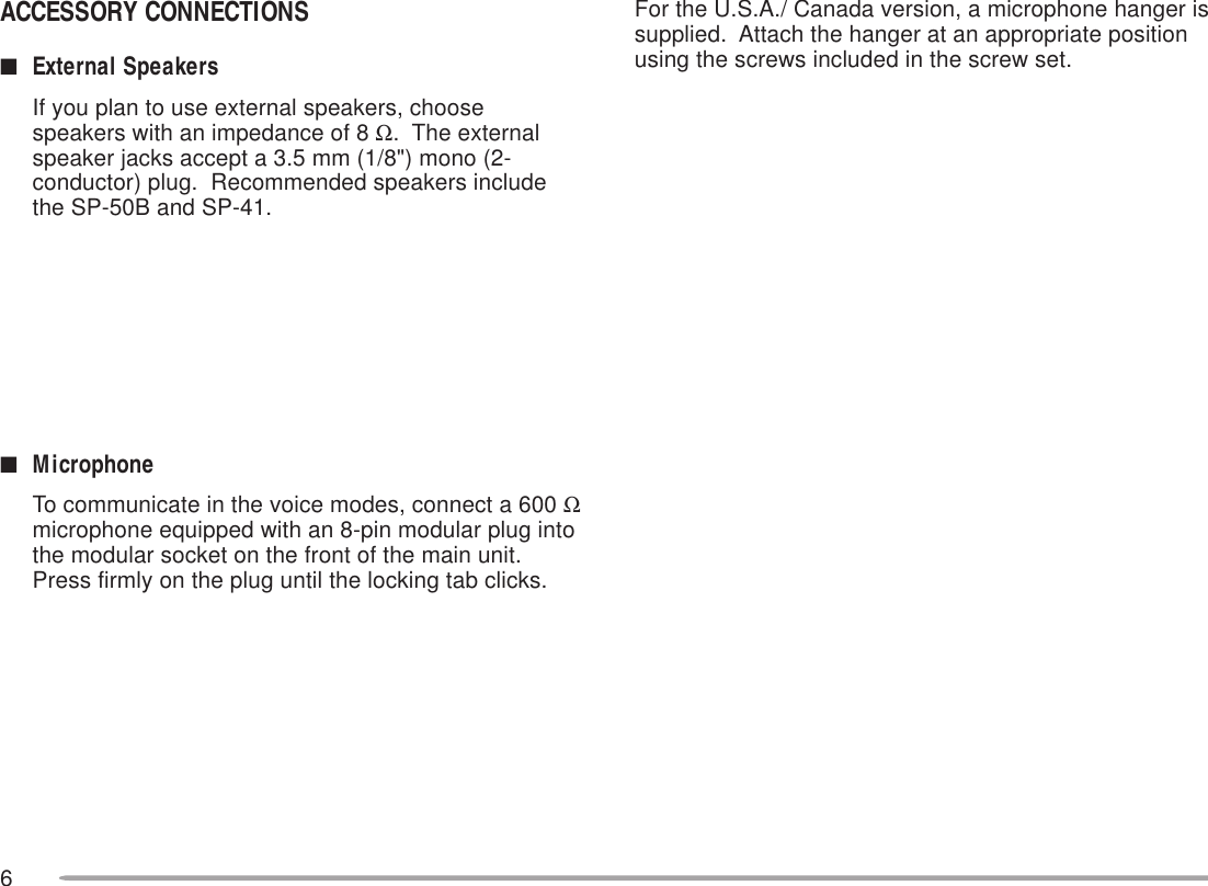
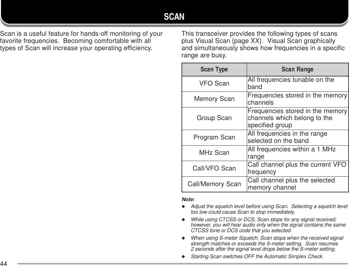
![8GETTING ACQUAINTEDFRONT PANELNote: This section describes only the main functions of the front panelcontrols and buttons. For the functions not described here, you will findexplanations in the appropriate sections of this manual.qqqqqCALL buttonRecalls the Call channel {page XX}. Also starts orstops Call/VFO Scan {page XX} when in VFO mode,or Call/Memory Scan {page XX} when in MemoryRecall mode.wwwwwVFO buttonSelects the VFO mode. In this mode you can changethe operating frequency, using the Tuning control orMic [UP]/ [DWN]. Also provides:• VFO Scan start to scan the entire VFO range{page XX}.• Program Scan start to scan a programmed range offrequencies {page XX}.eeeeeMR buttonSelects the Memory Recall mode {page XX}. In thismode you can change memory channels, using theTuning control or Mic [UP]/ [DWN]. Also startsMemory Scan {page XX}.rrrrrTuning controlSelects:• Operating frequencies when in VFO mode {page XX}.• Memory channels when in Memory Recall mode{page XX}.• Menu Nos. when in Menu mode {page XX}.This control is used for various other selections.When an up-arrow ( ) and down-arrow ( ) are visibleas button labels, the Tuning control functions in theexact same way as the up- and down-arrow keys.tttttMHz buttonSelects the MHz mode. In this mode you can changethe operating frequency in 1 MHz steps or 10 MHzsteps {page XX}, using the Tuning control or Mic[UP]/ [DWN]. Also starts MHz Scan {page XX}.](https://usermanual.wiki/JVC-KENWOOD/28451110/User-Guide-59321-Page-10.png)
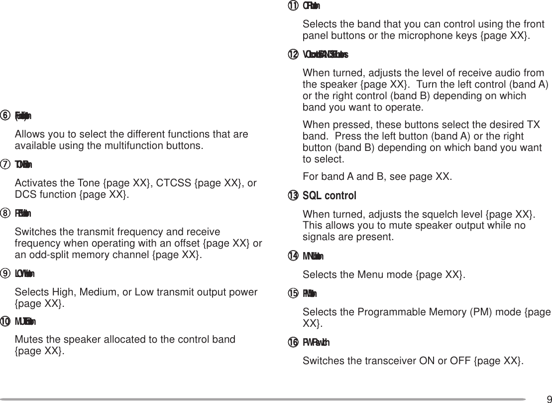
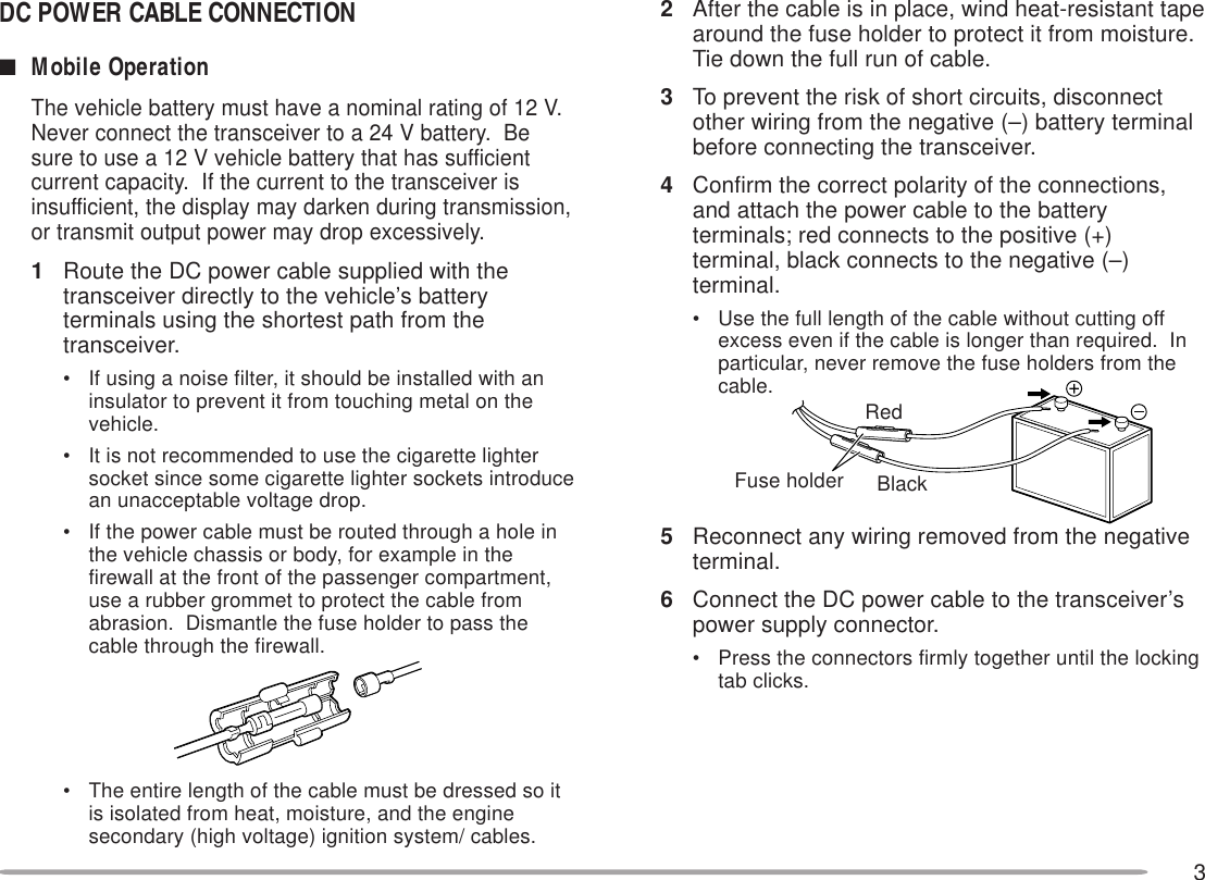
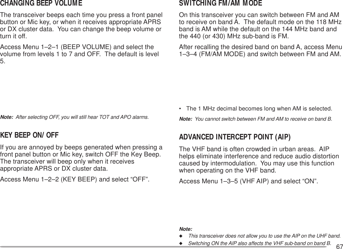
![11MICROPHONEqqqqqUP buttonwwwwwDWN buttonRaises or lowers the operating frequency, thememory channel number, the menu number, etc.Holding either button down causes the action to berepeated. Also, switches between values forfunctions with multiple choices.eeeeePTT (Push-to-talk) switchPress and hold to transmit, then release to receive.rrrrrLOCK switchLocks all microphone keys except [PTT] and (ifequipped) the DTMF keypad.tttttCALL keyyyyyyVFO keyuuuuuMR keyIdentical to the front panel CALL, VFO and MRbuttons. These keys can be re-programmed, ifdesired {page XX}.iiiiiPF keyDepending on which function you select in Menu 1–8–1 (PF1) {page XX}, the function of this key differs.Refer to “PROGRAMMABLE FUNCTION (PF) KEYS”{page XX}.oooooDTMF keypad (MC-53DM only)The 16-key keypad is used for DTMF functions{page XX}, or to directly enter a frequency or amemory channel number {page XX}. The keypad isalso available to program a memory channel name{pages XX and XX}, Power-ON message {page XX},or other character strings.8MICLOCKELECTRET CONDENSER MICMADE IN JAPANDWN UPVFO MR PFCALL3542167412376568MC-53DM MC-45](https://usermanual.wiki/JVC-KENWOOD/28451110/User-Guide-59321-Page-13.png)
![12INDICATORSOn the display you will see various indicators that showwhat you have selected.1 TM-D700E onlyFor the indicators that will show the current TNC status,see the table in “OPERATING TNC” {page XX}.When you receive a signal:• “BUSY” appears when the squelch {page XX} is open.• The S-meter shows the strength of received signals.rotacidnI uoYtahW detceleS otsserPuoYtahW lecnaC .feR egaPnoitcnufenoT ]ENOT[ ,]ENOT[ ,]ENOT[ XXSSCTC ]ENOT[ ,]ENOT[ XXSCD ]ENOT[ XXtesffosulP noitcerid]F[ ,]TFIHS[ ,]F[ ,]TFIHS[eno:E007D-MT( erom ]F[ ,]TFIHS[ )XXtesffosuniM noitcerid]F[ ,]TFIHS[eno:E007D-MT( erom ]F[ ,]TFIHS[ )XXtesffosuniM noitcerid )zHM6.7–(1]F[ ,]TFIHS[ XXesreveR ]VER[ XXcitamotuA kcehCxelpmiS ]VER[ XXtimsnarthgiH rewop tluafeDXXmuideM rewoptimsnart ]WOL[ ,]WOL[ ot tluafedehttceles XXtimsnartwoL rewop ]WOL[ tcelesot tluafedeht XXrotacidnI uoYtahW detceleS otsserPuoYtahW lecnaC .feR egaPtuo-dekcoL yromem lennahc .1–4–1uneMesUXXetuMrekaepS ]ETUM[ XXedomtekcaP )s1(]F[ ,]CNT[ ,)s1(]F[ ,]CNT[ XXedomSRPA )s1(]F[ ,]CNT[ XXtimsnartworraN noitaived .7–3–1uneMesUXX](https://usermanual.wiki/JVC-KENWOOD/28451110/User-Guide-59321-Page-14.png)
![13BASIC TRANSCEIVER MODESThis section introduces you to the basic modes you canselect.VFO modePress [VFO] to select. You can change the operatingfrequency using the Tuning control or Mic [UP]/ [DWN].Memory Recall modePress [MR] to select. You can change memorychannels, using the Tuning control or Mic [UP]/ [DWN],where you stored frequencies and related data. Refer to“MEMORY CHANNELS” {page XX}.Programmable Memory (PM) modePress [PM] to select. You can select the transceiverenvironment, by pressing [1] to [5], that you stored inPM channels. Refer to “PROGRAMMABLE MEMORY”{page XX}.Menu modePress [MNU] to select. You can change Menu Nos.using the Tuning control or [UP]/ [DWN]. Refer to“MENU SET-UP” {page XX}.Packet modePress [F] (1 s), [TNC] to select. You can sendcommands to the built-in TNC from a personal computer.Refer to “PACKET OPERATION” {page XX}.](https://usermanual.wiki/JVC-KENWOOD/28451110/User-Guide-59321-Page-15.png)
![14BUTTON FUNCTION DISPLAYThe functions of the 6 buttons below the display can beidentified through the labels shown at the bottom of thedisplay. After pressing [F] or [F] (1 s), pressing [F]([OFF]) again restores the basic state.Note:◆When selecting Programmable Memory (PM) mode, you will seedifferent labels. See “Programmable Memory (PM) mode” {page X}.◆You can also select different combinations of buttons labels. See“CHANGING MULTI-FUNCTION BUTTON LABELS ” {page XX}.The labels of the 5 buttons beside the display are shownat the left end or right end of the display. These labelswill change depending on the current mode.](https://usermanual.wiki/JVC-KENWOOD/28451110/User-Guide-59321-Page-16.png)
![15BAND A & BIn this manual, the band recalled at the left hand on thedisplay is referred to as band A, and the band at the righthand is called band B. The band A default is VHF (144MHz) and the band B default is UHF (440 or 430 MHz).In band A you can also recall a 118 MHz or UHF sub-band. In band B you can also recall a VHF (144 MHz)sub-band.This transceiver is capable of simultaneously receivingon 2 bands (A and B). So, for example, it is possible toreceive packet data on one VHF frequency whilereceiving audio on another VHF frequency. “ ” indicatesthe current data band {page XX}.Press the left or right [BAND SEL] to select band A or B.To recall the sub-band, press [F], then the same [BANDSEL]. The following diagram should help youunderstand how to select or recall the desired band.Note:◆You cannot recall a sub-band in Memory Recall mode. First press[VFO] to select VFO mode.◆You cannot recall the UHF sub-band in band A and the VHF sub-band in band B at the same time.◆The 118 MHz band cannot be used for transmitting.TX BAND AND CONTROL BANDWhat confuses you on this radio first could be the ideasof the TX band and Control band. Learn the differencesbetween these bands.TX BandPress the left [BAND SEL] (band A) or the right [BANDSEL] (band B) to select. “PTT” on the display showswhich band (A or B) is currently selected as the transmit(TX) band. You can use the TX band to transmit signalsor to control the transceiver.Control BandPress [CTRL] to select. On the display “Ctrl” appears toshow which band (A or B) is currently selected as theControl band. Use this function when you want tocontrol the band which is not currently used fortransmitting. After selecting the Control band, youcannot control the TX band.](https://usermanual.wiki/JVC-KENWOOD/28451110/User-Guide-59321-Page-17.png)
![16MIC KEYPAD DIRECT ENTRY(U.S.A./ CANADA ONLY)The keypad on the MC-53DM allows you to makevarious entries depending on which mode thetransceiver is in.In VFO or Memory Recall mode, use the Mic keypad toselect a frequency {page XX} or memory channelnumber {page XX}. In Tone or CTCSS freq. Selectmode, use the Mic keypad to select a Tone frequency{page XX} or CTCSS frequency {page XX}. First pressthe Mic PF key programmed as the ENTER key {pageXX}.To manually send a DTMF number, press and hold Mic[PTT], then press the DTMF keys on the Mic keypad{page XX} in sequence.You can also use the Mic keypad to program a memorychannel name {pages XX and XX}, Power-ON message{page XX}, or other character strings. Each press of aMic key switches entry of characters as below:1 qz1QZ 6 mno6MNO2 abc2ABC 7 prs7PRS3 def3DEF 8 tuv8TUV4 ghi4GHI 9 wxy9WXY5 jkl5JKL 0ecapS0#?!'.,-/&#()<>;:"@](https://usermanual.wiki/JVC-KENWOOD/28451110/User-Guide-59321-Page-18.png)
![17OPERATING BASICSADJUSTING VOLUMETurn the VOL control clockwise to increase the audiolevel and counterclockwise to decrease the audio level.• If background noise is inaudible because of the Squelchfunction, press the Mic PF key assigned the Monitorfunction {page XX}, then adjust the VOL control. Press thePF key again to cancel the Monitor function.SELECTING A BANDPress the right [BAND SEL] to select band A, or the left[BAND SEL] to select band B.• “PTT” moves to the selected band.• For band A and B, see page XX.SWITCHING POWER ON/OFF1Switch ON the DC power supply.• If operating mobile, skip this step.2Press the PWR switch to switch ON the transceiver.3To switch OFF the transceiver, press the PWR switchagain.4If operating as a fixed station, switch OFF the DCpower supply.• You may skip step 3. After switching ON the transceiver,you can switch it OFF or ON using only the power switchon the DC power supply.](https://usermanual.wiki/JVC-KENWOOD/28451110/User-Guide-59321-Page-19.png)
![18ADJUSTING SQUELCHThe purpose of the Squelch it to mute the speaker whenno signals are present. With the squelch level correctlyset, you will hear sound only when actually receivingsignals. The higher the squelch level selected, thestronger the signals must be to receive. The appropriatesquelch level depends on ambient noise conditions.Turn the SQL control when no signals are present.Select the squelch level at which the background noiseis just eliminated.The current squelch level is incorrect.The current squelch level is correct.SELECTING A FREQUENCY1Press [VFO] to select VFO mode.2To increase the frequency, turn the Tuning controlclockwise or press Mic [UP].To decrease the frequency, turn the Tuning controlcounterclockwise or press Mic [DWN].• Pressing and holding Mic [UP]/ [DWN] causes thefrequency to step repeatedly.• To change frequencies in steps of 1 MHz, press [MHz]first. Pressing [MHz] again cancels this function.• To change frequencies in steps of 10 MHz, press[F]+[MHz] first; do not press [F] for longer than1 second. Pressing [F] cancels the 10 MHz function;pressing [MHz] starts the 1 MHz function.You can also select frequencies via the microphonekeypad. See “DIRECT FREQUENCY ENTRY” {pageXX}.](https://usermanual.wiki/JVC-KENWOOD/28451110/User-Guide-59321-Page-20.png)
![19TRANSMITTING1To transmit, press and hold Mic [PTT] and speak intothe microphone in a normal tone of voice.• “ON AIR” and the RF power meter appear.• Speaking too close to the microphone, or too loudly,may increase distortion and reduce intelligibility of yoursignals at the receiving station.• The RF power meter shows the relative transmit outputpower.2When you finish speaking, release Mic [PTT].Time-Out Timer: Holding down Mic [PTT] for more than 10 minutescauses the transceiver to generate a beep and stop transmitting.Release, then press Mic [PTT] to resume transmitting. You may changethe time-out time to 3 or 5 minutes {page XX}.■Selecting Output PowerIt’s wise to select lower transmit power ifcommunication is still reliable. This lowers the risk ofinterfering with others on the band. When operatingfrom battery power, you will enjoy more operatingtime before a charge is necessary.Press [LOW] to select high (“H”), medium (“M”), orlow (“L”) power. The default is high.• You can program a different power for band A and B.◆Do not transmit at high output power for an extended period oftime. The transceiver could overheat and malfunction.◆Continuous transmission causes the heat sink to overheat.Never touch the heat sink when it may be hot.Note: When the transceiver overheats because of ambient hightemperature or continuous transmission, the protective circuit mayfunction to lower transmit output power.](https://usermanual.wiki/JVC-KENWOOD/28451110/User-Guide-59321-Page-21.png)
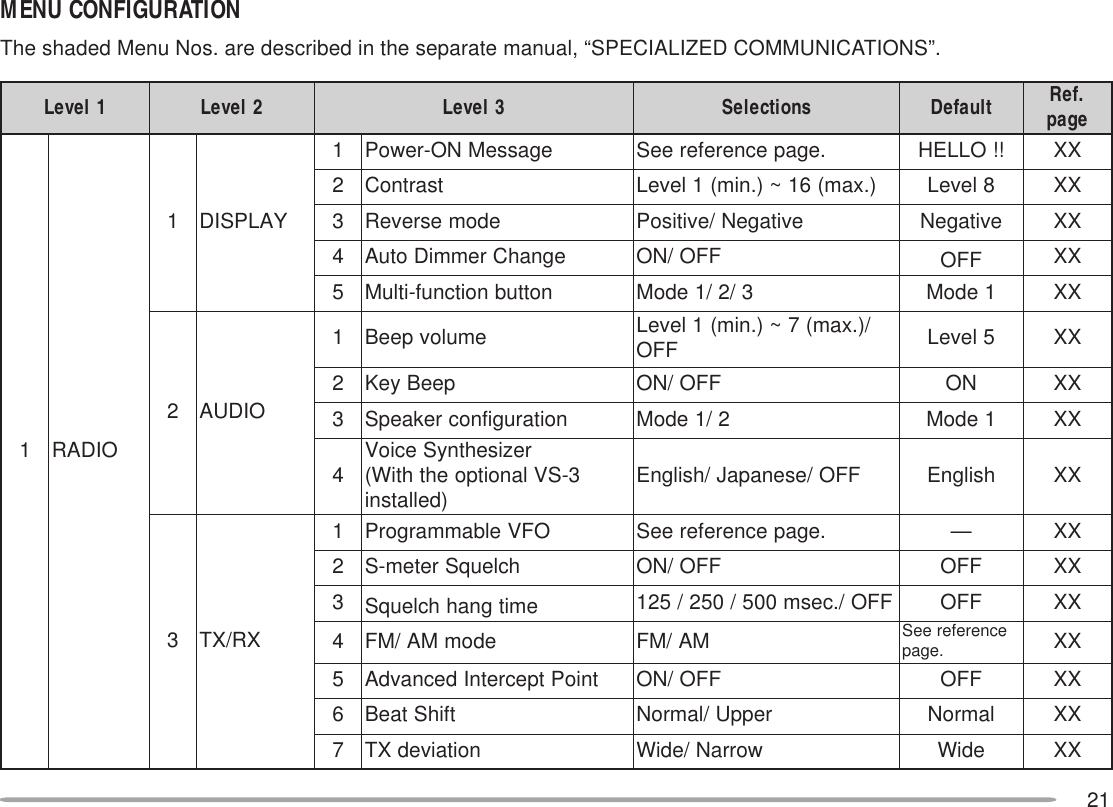
![20MENU SET-UPThe Menu system on this transceiver consists of 3levels.MENU ACCESS1Press [MNU] to enter Menu mode.• The current level 1 No. blinks.2Press [UP]/ [DWN] to select the appropriate level 1No.3Press [OK].• The current level 2 No. blinks.4Press [UP]/ [DWN] to select the appropriate level2 No.• To move back to level 1, press [BACK] instead.• To exit Menu mode, press [ESC].5Press [OK].6For Menu 1–1 to 1–9 and 1–A, repeat steps 4 and5 to select level 3.7Press [UP]/ [DWN] to select a parameter.• The procedure in this step differs depending onwhich menu item you selected. See the appropriatesections in this manual.8Press [OK] to complete the setting.9Press [MENU] to exit Menu mode.](https://usermanual.wiki/JVC-KENWOOD/28451110/User-Guide-59321-Page-22.png)
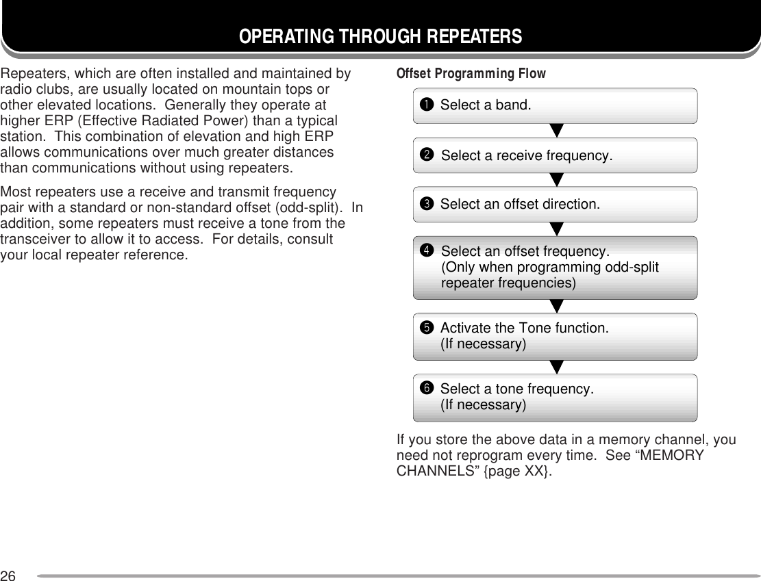
![27PROGRAMMING OFFSETFirst select band A or B by pressing the left or right[BAND SEL]. To recall the sub-band next, press [F],then the same [BAND SEL].■Selecting Offset DirectionSelect whether the transmit frequency will be higher(+) or lower (–) than the receive frequency.Press [F], [SHIFT] to switch the offset direction.• “+” or “–” appears to indicate which offset direction isselected.• To program –7.6 MHz offset on the TM-D700E (UHFonly), repeatedly press [F], [SHIFT] until “=” appears.If the offset transmit frequency falls outside theallowable range, transmitting is inhibited. Use one ofthe following methods to bring the transmit frequencywithin the band limits:• Move the receive frequency further inside the band.• Change the offset direction.Note: While using an odd-split memory channel or transmitting, youcannot change the offset direction.■Selecting Offset FrequencyTo access a repeater which requires an odd-splitfrequency pair, change the offset frequency from thedefault which is used by most repeaters. The defaultoffset frequency on the VHF band is 600 kHz nomatter which market version; the default on the UHFband is 5 MHz (TM-D700A) or 1.6 MHz (TM-D700E).1Press [MNU] to enter Menu mode.2Press [UP]/ [DWN] to select “RADIO (1–)”, thenpress [OK].3Press [UP]/ [DWN] to select “REPEATER (1–7–)”,then press [OK].4Press [UP]/ [DWN] to select “OFFSETFREQUENCY (1–7–1)”, then press [OK].5Press [UP]/ [DWN] to select the appropriate offsetfrequency.• The selectable range is from 0.00 MHz to 29.95 MHzin steps of 50 kHz.6Press [OK] to complete the setting.7Press [MNU] to exit Menu mode.TM-D700E Only: If you have selected “ =” for the offset direction,you cannot change the default (7.6 MHz).Note: After changing the offset frequency, the new offset frequencywill also be used by Automatic Repeater Offset.](https://usermanual.wiki/JVC-KENWOOD/28451110/User-Guide-59321-Page-29.png)
![282Press [UP]/ [DWN] to select the appropriate tonefrequency.3Press [OK] to complete the setting.After programming one of the Mic PF keys as theENTER key {page XX}, you can also select a tonefrequency by direct entry from the Mic keypad. Instep 2, press [ENTER], then enter 01 to 38 shown inthe table. To select 100 Hz, for example, press[ENTER], [0], [1], [2].■Activating Tone FunctionPress [TONE] to activate the Tone function.• “T” appears when the Tone function is ON.• Each press of [TONE] changes the selection as Tone –>CTCSS –> DCS –> No selection.Note:◆You cannot use the Tone function with the CTCSS or DCSfunction.◆You need to activate the Tone function only when selecting oneof the 38 standard frequencies. The selection you make here willnot affect transmission of a 1750 Hz tone.■Selecting a Tone FrequencyNote: The procedures for transmitting a 1750 Hz tone are describedon page XX.1Press [F], [T.SEL].• The current tone frequency appears and blinks. Thedefault is 88.5 Hz..oN .qerF )zH( .oN .qerF )zH( .oN .qerF )zH( .oN .qerF )zH(100.76114.79125.631138.291209.17210.001223.141235.302304.47315.301322.641337.012400.77412.701424.151431.812507.97519.011527.651537.522605.28618.411622.261636.332704.58718.811729.761738.142805.88810.321828.371833.052905.19913.721929.971018.49028.131032.681](https://usermanual.wiki/JVC-KENWOOD/28451110/User-Guide-59321-Page-30.png)
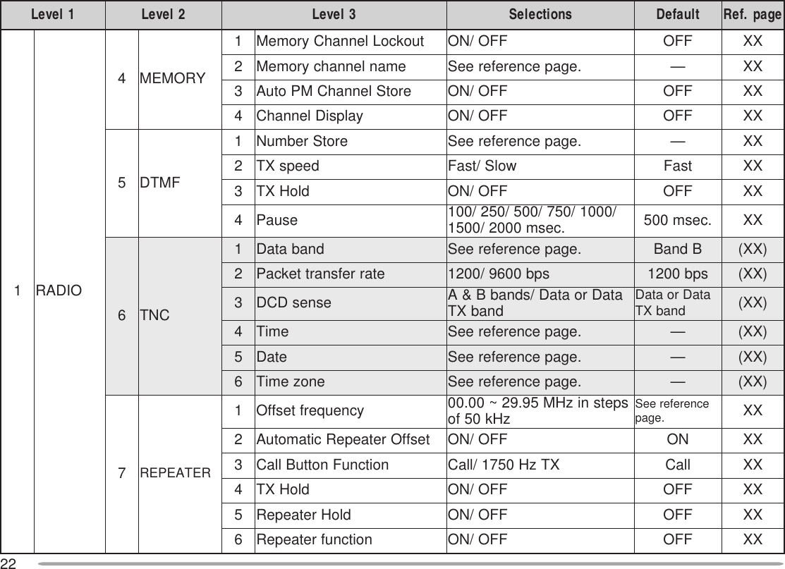
![29AUTOMATIC REPEATER OFFSETThis function automatically selects an offset direction,according to the frequency that you select on the VHFband. The transceiver is programmed for offset directionas shown below. To obtain an up-to-date band plan forrepeater offset direction, contact your national AmateurRadio association.U.S.A. and Canada versionsThis complies with the standard ARRL band plan.European versionsNote: Automatic Repeater Offset does not function when Reverse is ON.However, pressing [REV] after Automatic Repeater Offset has selectedan offset (split) status, exchanges the receive and transmit frequencies.1Press [MNU] to enter Menu mode.2Press [UP]/ [DWN] to select “RADIO (1–)”, thenpress [OK].3Press [UP]/ [DWN] to select “REPEATER (1–7–)”,then press [OK].4Press [UP]/ [DWN] to select “AUTO OFFSET (1–7–2)”, then press [OK].5Press [UP]/ [DWN] to switch the function ON(default) or OFF.6Press [OK] to complete the setting.7Press [MNU] to exit Menu mode.+−−− +SSSS144.0 145.5 146.4 147.0 147.6145.1 146.0 146.6 147.4 148.0 MHzS: SimplexSSS: Simplex–144.0 146.0 MHz145.8145.6](https://usermanual.wiki/JVC-KENWOOD/28451110/User-Guide-59321-Page-31.png)
![30TRANSMITTING A 1750 Hz TONEMost of the repeaters in Europe require that atransceiver transmit a 1750 Hz tone. On a TM-D700E,simply pressing Mic [CALL] causes it to transmit a 1750Hz tone. It is also possible to program [CALL] on thefront panel as a button for transmitting a 1750 Hz tone.1Press [MNU] to enter Menu mode.2Press [UP]/ [DWN] to select “RADIO (1–)”, thenpress [OK].3Press [UP]/ [DWN] to select “REPEATER (1–7–)”,then press [OK].4Press [UP]/ [DWN] to select “1750Hz TONE (1–7–3)”, then press [OK].5Press [UP]/ [DWN] to select “1750 Hz”.6Press [OK] to complete the setting.7Press [MNU] to exit Menu mode.• “1750” appears in place of “CALL” as the button label.Note:◆All market versions allow the above selection in Menu 1–7–3.◆All market versions allow any Mic PF key to be assigned the 1750 HzTone function {page XX}.◆The transceiver continuously transmits a 1750 Hz tone until yourelease Mic [CALL], or [CALL].Some repeaters in Europe must receive continuoussignals for a certain period of time, following a 1750 Hztone. This transceiver is also capable of remaining in thetransmit mode for 2 seconds after transmitting a 1750 Hztone.1Press [MNU] to enter Menu mode.2Press [UP]/ [DWN] to select “RADIO (1–)”, thenpress [OK].3Press [UP]/ [DWN] to select “REPEATER (1–7–)”,then press [OK].4Press [UP]/ [DWN] to select “TX HOLD (1–7–4)”,then press [OK].5Press [UP]/ [DWN] to switch the function ON (orOFF).6Press [OK] to complete the setting.7Press [MNU] to exit Menu mode.Note:◆All market versions allow the above selection in Menu 1–7–4.◆While remaining in the transmit mode, the transceiver does notcontinuously transmit a 1750 Hz tone.](https://usermanual.wiki/JVC-KENWOOD/28451110/User-Guide-59321-Page-32.png)
![31AUTOMATIC SIMPLEX CHECK (ASC)While using a repeater, ASC periodically monitors thestrength of a signal that you receive directly from theother station. If the station’s signal is strong enough toallow direct contact without a repeater, the ASC indicatoron the display begins blinking.Press [REV] (1 s) to switch the function ON.• The ASC indicator appears when the function is ON.• While direct contact is possible, the ASC indicator blinks.• To quit the function, press [REV].Note:◆Pressing Mic [PTT] causes the ASC indicator to quit blinking.◆ASC does not function if your transmit and receive frequencies arethe same (simplex operation).◆ASC does not function while scanning.◆Activating ASC while using Reverse switches Reverse OFF.◆If you recall a memory channel or the Call channel that containsReverse ON status, ASC is switched OFF.◆ASC causes receive audio to be momentarily intermitted every 3seconds.REVERSE FUNCTIONThe reverse function exchanges a separate receive andtransmit frequency. So, while using a repeater, you canmanually check the strength of a signal that you receivedirectly from the other station. If the station’s signal isstrong, both stations should move to a simplex frequencyand free up the repeater.Press [REV] to switch the Reverse function ON (orOFF).• “R” appears when the function is ON.Note:◆If pressing [REV] places the transmit frequency outside the allowablerange, then pressing Mic [PTT] causes an error beep to sound;transmission is inhibited.◆If pressing [REV] places the receive frequency outside the allowablerange, an error beep sounds and no reversal occurs.◆Automatic Repeater Offset does not function while Reverse is ON.◆You cannot switch Reverse ON or OFF while transmitting.](https://usermanual.wiki/JVC-KENWOOD/28451110/User-Guide-59321-Page-33.png)
![322Press [OK] to program the identified frequency inplace of the currently set tone frequency.• The previous frequency display is restored with the Tonefunction remained ON. You may press [TONE] to switchthe Tone function OFF.• Press [ESC] if you do not want to program the identifiedfrequency.• Press [SCAN] while the identified frequency is blinking,to resume scanning.TONE FREQ. IDThis function scans through all tone frequencies toidentify the incoming tone frequency on a receivedsignal. You may use the function to find which tonefrequency is required by your local repeater.1Press [TONE] to switch ON the Tone function.• “T” appears when the Tone function is ON.2Press [F], [T.SEL].• The current tone frequency appears and blinks.3Press [SCAN] to activate the Tone Freq. ID.“T SCAN” appears.• To reverse the scan direction, turn the Tuning controlclockwise (upward scan) or counterclockwise(downward scan). You can also press Mic [UP]/ [DWN].• To quit the function, press [ESC].•When the tone frequency is identified, the identifiedfrequency appears and blinks.](https://usermanual.wiki/JVC-KENWOOD/28451110/User-Guide-59321-Page-34.png)
![34STORING ODD-SPLIT REPEATER FREQUENCIESSome repeaters use a receive and transmit frequencypair with a non-standard offset. If you store two separatefrequencies in a memory channel, you can operate onthose repeaters without programming the offsetfrequency and direction.1Select the desired receive frequency and related databy using steps 1 to 4 given for simplex or standardrepeater frequencies.2Press [F].3Turn the Tuning control, or press Mic [UP]/ [DWN], toselect the desired memory channel.4Press [M.IN] (1 s).•“±” appears and the receive frequency blinks.5Select the desired transmit frequency (withinapprox.10 seconds).6Press [M.IN].Note:◆When you recall an odd-split memory channel, “±” appears on thedisplay. To confirm the transmit frequency, press [REV].◆Transmit Offset status and Reverse status are not stored in an odd-split memory channel.STORING SIMPLEX FREQUENCIES OR STANDARDREPEATER FREQUENCIES1Select the desired band.2Press [VFO].3Select the desired frequency.4If storing a standard repeater frequency, select thefollowing data:• Offset direction {page XX}• Tone ON, if necessary {page XX}• Tone frequency, if necessary {page XX}If storing a simplex frequency, you may select otherrelated data (CTCSS ON, CTCSS freq., etc.).5Press [F].• A memory channel number appears and blinks.•“ ” indicates the current channel is empty; “ ” appearsinstead, if the channel contains data.6Turn the Tuning control, or press Mic [UP]/ [DWN], toselect the desired memory channel.7Press [M.IN].](https://usermanual.wiki/JVC-KENWOOD/28451110/User-Guide-59321-Page-36.png)
![35CLEARING A MEMORY CHANNELUse the following procedure to clear an individualmemory channel. Full Reset {page XX} is a quick way toclear all memory channels.1Recall the desired memory channel.2Switch OFF the power to the transceiver.3Press [MHz]+ POWER ON.• A confirmation message appears.• To quit clearing the memory channel, press [ESC].4Press [OK].Note:◆If you have recalled a memory channel on the non-control band (A orB), you cannot select the same channel on the control band to clear.◆When in Channel Display mode, you cannot clear any memorychannel.RECALLING A MEMORY CHANNEL1Select the desired band.2Press [MR] to enter Memory Recall mode.• The memory channel used last is recalled.3Turn the Tuning control, or press [UP]/ [DWN], toselect the desired memory channel.• You cannot recall an empty memory channel.• To restore VFO mode, press [VFO].After programming one of the Mic PF keys as theENTER key {page XX}, you can also recall a memorychannel by direct entry from the Mic keypad. In MemoryRecall mode press [ENTER], then enter the channelnumber. To recall channel 3, for example, press[ENTER], [0], [0], [3].Note:◆When you recall an odd-split memory channel, “±” appears on thedisplay. Press [REV] to display the transmit frequency.◆After recalling a memory channel, you may program data such asTone or CTCSS. These settings, however, are cleared once youselect another channel or the VFO mode. To permanently store thedata, overwrite the channel contents {page XX}.](https://usermanual.wiki/JVC-KENWOOD/28451110/User-Guide-59321-Page-37.png)
![368Repeat steps 6 and 7 to enter up to 8 digits.9Press [OK] to complete the setting.10 Press [MNU] to exit Menu mode.The keypad on the MC-53DM also is available to enteralphanumeric characters in step 6. See page XX.Note:◆You can also name the Program Scan {page XX} and DTMF{page XX} channels, but you cannot name the Call channel{page XX}.◆You can assign names only to memory channels in which you havestored frequencies and related data.◆The stored names can be overwritten by repeating steps 1 to 10.◆The stored names also are erased by clearing memory channels.NAMING A MEMORY CHANNELYou can name memory channels using up to 8alphanumeric characters. When you recall a namedmemory channel, its name appears on the displayinstead of the stored frequency. Names can be callsigns, repeater names, cities, names of people, etc.1Recall the desired memory channel.2Press [MNU] to enter Menu mode.3Press [UP]/ [DWN] to select “RADIO (1–)”, thenpress [OK].4Press [UP]/ [DWN] to select “MEMORY (1–4–)”, thenpress [OK].5Press [UP]/ [DWN] to select “MEMORY NAME (1–4–2)”, then press [OK].6Turn the Tuning control to select the first digit.• You can enter alphanumeric characters plus specialASCII characters.7Press [->].• The cursor moves to the next digit.RAHC ciremunahplafostesehtgnomasehctiwS ,)ylnoE007D-MT(sretteldetnecca,sretcarahc .sretcarahcIICSAlaicepsdnaA/a neewtebsehctiwS latipacdnallams .srettel KCAB yromeMslecnaC .yrtnEemaNLED tatigidehtseteleD sirosrucehthcihw .gniknilb -< rosrucehtsesuaC .drawkcabevomotSNI taecapsastresnI sirosrucehthcihw .gniknilb RLC dnastigidllasraelC otrosrucehtskcab .tigidtsrifeht](https://usermanual.wiki/JVC-KENWOOD/28451110/User-Guide-59321-Page-38.png)
![37CALL CHANNELThe Call channel can always be selected quickly nomatter what mode the transceiver is in. For instance,you may use the Call channel as an emergencychannel within your group. In this case, the Call/VFOscan {page XX} will be useful.The default frequency stored in the Call channel is144.000 MHz for the VHF band. The default on the UHFband is 440.000 MHz or 430.000 MHz depending on themarket versions. The Call channel can bereprogrammed either as a simplex & repeater or odd-split channel.Note: Unlike channels 1 to 200 the call channel cannot be cleared.■Recalling the Call Channel1Select the desired band.2Press [CALL] to recall the Call channel.• “CALL” appears.• To restore the previous mode, press [CALL] again.■Reprogramming the Call Channel1Select the desired band.2Press [VFO].3Select the desired frequency and related data(Tone, CTCSS, etc.).• When you program the Call channel as an odd-splitchannel, select a receive frequency.4Press [F], [C.IN].• The selected frequency and related data are storedin the Call channel.• The previous mode is restored.• When programming as an odd-split channel, press[F], [C.IN] (1 s) instead; “±” appears.To also store a transmit frequency, proceed to thenext step.5Select the desired transmit frequency.6Press [C.IN].• The transmit frequency is stored in the Call channel,and the previous mode is restored.Note:◆Transmit Offset status and Reverse status are not stored in anodd-split Call channel.◆To store data other than frequencies, select the data in step 3 notstep 5.](https://usermanual.wiki/JVC-KENWOOD/28451110/User-Guide-59321-Page-39.png)
![38MEMORY-TO-VFO TRANSFERYou may sometimes want to search for other stations ora clear frequency, near the frequency stored in amemory channel or the Call channel. In this case firsttransfer the contents of a memory channel or the Callchannel to the VFO.1Recall the desired memory channel or the Callchannel.2Press [F], [M>V].• The entire contents of the memory channel or the Callchannel are copied to the VFO.Note:◆A transmit frequency from an odd-split memory channel or odd-splitCall channel is not transferred to the VFO. To transfer a transmitfrequency, press [REV], then press [F], [M>V].◆Lockout status and memory names are not copied from a memorychannel to the VFO.◆If you recall the Call channel in step 1, simply turning the TuningControl or pressing Mic [UP]/ [DWN] also transfers the contents tothe VFO. The frequency, however, is changed by one step.CHANNEL DISPLAYWhen in this mode, the transceiver displays onlymemory channel numbers (or memory names if stored)instead of frequencies.1Press [MNU] to enter Menu mode.2Press [UP]/ [DWN] to select “RADIO (1–)”, thenpress [OK].3Press [UP]/ [DWN] to select “MEMORY (1–4–)”, thenpress [OK].4Press [UP]/ [DWN] to select “CHANNEL DISPLAY(1–4–4)”, then press [OK].5Press [UP]/ [DWN] to switch the function ON (orOFF).6Press [OK] to complete the setting.7Press [MNU] to exit Menu mode.Note: You cannot switch this function ON if you have not used bothbands A and B to store frequencies.When in Channel Display mode, you cannot use thefollowing functions:tceleSdnab-buStceleSOFVnacSOFVerotSyromeMerotSMPllaceRMPOFV-ot-yromeM refsnarT teseRMP/lluF/laitraP xelpmiScitamotuA kcehCkcoLlortnoc-llAnoitartsnomeDyalpsiD](https://usermanual.wiki/JVC-KENWOOD/28451110/User-Guide-59321-Page-40.png)
![39PARTIAL OR FULL RESET?If your transceiver seems to be malfunctioning,initializing the transceiver may resolve the problem. UseFull Reset to initialize all settings that you havecustomized. Partial (VFO) Reset does not initialize thefollowing settings:Some of the VFO factory defaults are listed below:1Press [MNU] to enter Menu mode.2Press [UP]/ [DWN] to select “RADIO (1–)”, thenpress [OK].3Press [UP]/ [DWN] to select “AUX (1–9–)”, thenpress [OK].4Press [UP]/ [DWN] to select “RESET (1–9–7)”, thenpress [OK].5Press [UP]/ [DWN] to select Partial (VFO) Reset, PMReset {page XX}, or Full Reset, then press [OK].• A confirmation message appears.6Press [OK].After switching the power OFF, you may press [VFO]+POWER ON for Partial Reset, or [MR]+ POWER ON forFull Reset. This allows you to skip steps 1 to 5.You can also use the RESET button to perform Partial orFull Reset. See page XX.Note: When in All-control Lock or Channel Display mode, you cannotperform Partial Reset nor Full Reset.slennahcyromeMslennahcllaCslennahcnacsmargorPslennahcMPtuokcollennahcyromeMretemaraP AdnaB BdnaB.qerfOFVzHM000.441 zHM000.044 ro)adanaC/.A.S.U( zHM000.034:pets.qerF /.A.S.U(zHk5.21 zHk5ro)adanaC zHk52:.qerfenoTzH5.88zH5.88](https://usermanual.wiki/JVC-KENWOOD/28451110/User-Guide-59321-Page-41.png)
![42STORING IN PM CHANNELS1Confirm that the following conditions have beensatisfied:• The transceiver is in the receive mode.• Scan is not being used.• Microphone Control is OFF.2Select the desired band.3Select the desired frequency and related data (Tone,CTCSS, etc.) using VFO mode.4If required, select another band, then select thedesired frequency and related data.5Press [F], [P.IN].• The PM channel numbers appear and blink.6Press [1] to [5] corresponding to the desired PMchannel.• The selected frequency and related data are stored inthe PM channel.RECALLING A PM CHANNEL1Press [PM].• The PM channel numbers 1 to 5 appear at the bottom ofthe display.• The current PM channel number appears and blinks atthe upper right corner.• If in Auto PM Store mode {page XX}, the current PMchannel number appears with “>”; ex. >PM1.2Press [1] to [5] corresponding to the desired PMchannel.• The contents of the selected channel are recalled.• Press [OFF] to exit PM Recall mode,Note: You cannot recall a PM channel while transmitting.](https://usermanual.wiki/JVC-KENWOOD/28451110/User-Guide-59321-Page-44.png)
![43AUTO PM CHANNEL STOREAfter you recalled a PM channel, this functionautomatically overwrites the current PM channel with thepresent operating environment when:• You recall another PM channel.• You press [OFF].• You switch OFF the transceiver.The factory default of this function is ON.1Press [MNU] to enter Menu mode.2Press [UP]/ [DWN] to select “RADIO (1–)”, thenpress [OK].3Press [UP]/ [DWN] to select “MEMORY (1–4–)”, thenpress [OK].4Press [UP]/ [DWN] to select “AUTO PM STORE (1–4–3)”, then press [OK].5Press [UP]/ [DWN] to switch the function ON(default) or OFF.6Press [OK] to complete the setting.7Press [MNU] to exit Menu mode.PM CHANNEL RESETIf you want to reprogram the PM channels from thebeginning, reset all the PM channels to the factorydefaults.1Press [CALL]+ POWER ON.• A confirmation message appears.• Press [ESC] to quit resetting.2Press [OK].You can also use Menu 1–9–7 (RESET) to reset the PMchannels. See XX.](https://usermanual.wiki/JVC-KENWOOD/28451110/User-Guide-59321-Page-45.png)
![45VISUAL SCANWhile you are on the air, Visual Scan allows you tomonitor frequencies near the current operatingfrequency. Visual Scan graphically and simultaneouslyshows how all frequencies in the selected range arebusy. You will see up to 21 segments, for each channel,that represent 7 S-meter levels (3 segments per level).You will determine the scan range by selecting thecenter frequency and the number of channels. Thedefault number of channels is 61.■Selecting the Number of Channels1Press [MNU] to enter Menu mode.2Press [UP]/ [DWN] to select “RADIO (1–)”, thenpress [OK].3Press [UP]/ [DWN] to select “AUX (1–9–)”, thenpress [OK].4Press [UP]/ [DWN] to select “VISUAL SCAN (1–9–2)”, then press [OK].5Press [UP]/ [DWN] to select 31, 61 (default), 91,or 181.6Press [OK] to complete the setting.7Press [MNU] to exit Menu mode.](https://usermanual.wiki/JVC-KENWOOD/28451110/User-Guide-59321-Page-47.png)
![46Note:◆If you start Visual Scan in Memory Recall mode, the memorychannel frequencies will be scanned.◆If you start Visual Scan after recalling the Call channel, the callchannel frequency will be used as the center frequency.◆If the frequency range specified for Program Scan or ProgramVFO is narrower than the range specified for Visual Scan, therange for Program Scan or VFO will be used for Visual Scan.◆Visual Scan stops while transmitting.◆Starting Visual Scan switches Automatic Band Change OFF.◆If you start Visual Scan in one of the following conditions, youcannot receive in the current operating frequency. To use thisfrequency, press [PAUSE] to halt Scan.•Memory Recall or Call Channel mode•A frequency in the range 118 MHz to 136 MHz was selectedin VFO mode.◆Depending on conditions, Visual Scan and the conventional S-meter may indicate different signal strength levels.■Using Visual Scan1Select the desired band.2Turn the Tuning control, or press Mic [UP]/[DWN], to select the operating frequency.• This frequency will also be used as the centerfrequency.3Press [F], [VISUAL] to start Visual Scan.• To halt Scan, press [PAUSE]. “PAUSE” appears andblinks. Press [PAUSE] again to resume.4To change the operating frequency, turn theTuning control or press Mic [UP]/ [DWN].• The displayed frequency changes and the cursormoves.• Press [SET] to use the changed operating frequencyas the center frequency.• Press [RESET] to restore the previous operatingfrequency.5To quit Visual Scan, press [ESC].](https://usermanual.wiki/JVC-KENWOOD/28451110/User-Guide-59321-Page-48.png)
![471Press [MNU] to enter Menu mode.2Press [UP]/ [DWN] to select “RADIO (1–)”, thenpress [OK].3Press [UP]/ [DWN] to select “AUX (1–9–)”, thenpress [OK].4Press [UP]/ [DWN] to select “SCAN RESUME (1–9–1)”, then press [OK].5Press [UP]/ [DWN] to select Time-Operated (default),Carrier-Operated, or Seek.6Press [OK].7Press [MNU] to exit Menu mode.SELECTING SCAN RESUME METHODThe transceiver stops scanning at a frequency (ormemory channel) on which a signal is detected. It thencontinues scanning according to which resume modeyou select. You can choose one of the following modes.The default is Time-operated mode.•Time-Operated modeThe transceiver remains on a busy frequency (ormemory channel) for approximately 5 seconds, andthen continues to scan even if the signal is stillpresent.•Carrier-Operated modeThe transceiver remains on a busy frequency (ormemory channel) until the signal drops out. There isa 2 second delay between signal drop-out and scanresumption.•Seek modeThe transceiver remains on a busy frequency (ormemory channel) even after the signal drops out anddoes not automatically resume scanning.Note: To temporarily stop scanning and monitor weak signals, press andhold the Mic PF key assigned the Monitor function {page XX}. Releasethe key to resume scanning.](https://usermanual.wiki/JVC-KENWOOD/28451110/User-Guide-59321-Page-49.png)
![48MEMORY SCANUse Memory Scan to monitor all memory channelsprogrammed with frequency data.1Select the desired band.2Press [MR] (1 s).• Scan starts with the channel last recalled.• The 1 MHz decimal blinks while scanning is in progress.• To reverse the scan direction, turn the Tuning controlclockwise (upward scan) or counterclockwise(downward scan). You can also press Mic [UP]/ [DWN].3To quit Memory Scan, press [ESC].Note:◆On the current band at least 2 or more memory channels mustcontain data and must not be locked out.◆The L0 to L9 and U0 to U9 memory channels are not scanned.◆You can also start Memory Scan when in Channel Display mode.While Scan is being interrupted, the channel number blinks.VFO SCANVFO Scan monitors all frequencies tunable on the band,using the current frequency step size.1Select the desired band.2Press [VFO] (1 s).• Scan starts at the frequency currently displayed.• The 1 MHz decimal blinks while scanning is in progress.• To reverse the scan direction, turn the Tuning controlclockwise (upward scan) or counterclockwise(downward scan). You can also press Mic [UP]/ [DWN].3To quit VFO Scan, press [ESC].](https://usermanual.wiki/JVC-KENWOOD/28451110/User-Guide-59321-Page-50.png)
![49■Locking Out a Memory ChannelSelect memory channels that you prefer not tomonitor while scanning.1Recall the desired memory channel.2Press [MNU] to enter Menu mode.3Press [UP]/ [DWN] to select “RADIO (1–)”, thenpress [OK].3Press [UP]/ [DWN] to select “MEMORY (1–4–)”,then press [OK].4Press [UP]/ [DWN] to select “LOCKOUT (1–4–1)”,then press [OK].5Press [UP]/ [DWN] to switch Lockout ON (orOFF).6Press [OK] to complete the setting.7Press [MNU] to exit Menu mode.Note:◆The L0 to L9 and U0 to U9 memory channels cannot be lockedout.◆If you have recalled a memory channel on the non-control band(A or B), you cannot select the same channel on the control bandto lock out.GROUP SCANFor the purpose of Group Scan, the 200 memorychannels are divided into 10 groups, with each groupcontaining 20 channels. Group Scan monitors only the20 channels which belong to the specified group. Thechannels are grouped as below:1Recall one of the memory channels in the desiredgroup.2Press [MR] (1 s).• Scan starts with the channel last recalled.• The 1 MHz decimal blinks while scanning is in progress.• To reverse the scan direction, turn the Tuning controlclockwise (upward scan) or counterclockwise(downward scan). You can also press Mic [UP]/ [DWN].3To quit Group Scan, press [ESC].Note:◆At least 2 or more memory channels in the specified group mustcontain data and must not be locked out.◆You can also start Memory Scan when in Channel Display mode.While Scan is being interrupted, the channel number blinks.02~1.soN021~101.soN04~12.soN041~121.soN06~14.soN061~141.soN08~16.soN081~161.soN001~18.soN002~181.soN](https://usermanual.wiki/JVC-KENWOOD/28451110/User-Guide-59321-Page-51.png)
![506Press [M.IN].• The lower limit is stored in the channel.7Select the desired frequency as the upper limit.8Press [F].9Press [UP]/ [DWN] to select a matching channelin the range U0 to U9.• If you have selected for example L3 in step 5, selectU3.10 Press [M.IN].• The upper limit is stored in the channel.To confirm the stored scan limits, press [MR], thenselect the L and U channels.Note:◆The lower limit must be lower in frequency than the upper limit.◆The lower and upper frequency step sizes must be equal.◆The lower and upper limits must be selected on the same band.PROGRAM SCANProgram Scan is identical with VFO Scan except thatyou select the frequency range of the scan.■Setting Scan LimitsYou can store up to 10 scan ranges in memorychannels L0/U0 to L9/U9.1Select the desired band.2Press [VFO].3Select the desired frequency as the lower limit.4Press [F].• A memory channel number appears and blinks.5Turn the Tuning control, or press Mic [UP]/[DWN], to select a channel in the range L0 to L9.](https://usermanual.wiki/JVC-KENWOOD/28451110/User-Guide-59321-Page-52.png)
![51■Using Program Scan1Select the appropriate band.2Press [VFO] .3Select a frequency equal to or between theprogrammed scan limits.4Press [VFO] (1 s).• Scan starts at the frequency currently displayed.• The 1 MHz decimal blinks while scanning is inprogress.• To reverse the scan direction, turn the Tuningcontrol clockwise (upward scan) or counterclockwise(downward scan). You can also press Mic [UP]/[DWN].5To quit Program Scan, press [ESC].Note:◆If the step size of the current VFO frequency differs from that ofthe programmed frequencies, you cannot use Program Scan.◆If the step size differs between the lower limit and the upper limit,you cannot use Program Scan.◆If the current VFO frequency is within more than oneprogrammed scan range, the range stored in the smallestchannel number is used.MHz SCANMHz Scan monitors a 1 MHz segment of the band, usingthe current frequency step size. The current 1 MHz digitdetermines the limits of the scan. For example, if thecurrent frequency is 145.400 MHz, then the scan rangewould be from 145.000 MHz to 145.995 MHz. The exactupper limit depends on the current frequency step size.1Select the desired band.2Press [VFO] to select VFO mode.3Select a frequency within the desired 1 MHzsegment.4Press [MHz] (1 s) to start MHz Scan.• Scan starts at the frequency currently displayed.• The 1 MHz decimal blinks while scanning is in progress.• To reverse the scan direction, turn the Tuning controlclockwise (upward scan) or counterclockwise(downward scan). You can also press Mic [UP]/ [DWN].5To quit MHz Scan, press [ESC].](https://usermanual.wiki/JVC-KENWOOD/28451110/User-Guide-59321-Page-53.png)
![52CALL/VFO SCANUse Call/VFO Scan to monitor both the Call channel andthe current VFO frequency on the selected band.1Select the desired band.2Press [VFO].3Select the desired frequency.4Press [CALL] (1 s) to start Call/VFO Scan.• The 1 MHz decimal blinks while scanning is in progress.5To quit Call/VFO Scan, press [ESC].CALL/MEMORY SCANUse Call/Memory Scan to monitor both the Call channeland the desired memory channel.1Recall the desired memory channel.2Press [CALL] (1 s) to start Call/Memory Scan.• The 1 MHz decimal blinks while scanning is in progress.• The Call channel on the same band as of the selectedmemory channel is used for Scan.3To quit Call/Memory Scan, press [ESC].Note: The memory channel last used is scanned even if it has beenlocked out.](https://usermanual.wiki/JVC-KENWOOD/28451110/User-Guide-59321-Page-54.png)
![53CONTINUOUS TONE CODED SQUELCH SYSTEM (CTCSS)You may sometimes want to hear calls from only specificpersons. The Continuous Tone Coded Squelch System(CTCSS) allows you to ignore (not hear) unwanted callsfrom other persons who are using the same frequency.First select the same CTCSS tone as selected by theother persons in your group. A CTCSS tone issubaudible and is selectable from among the 38standard tone frequencies.Note: CTCSS does not cause your conversation to be private. It onlyrelieves you from listening to unwanted conversations.USING CTCSS1Press the left or right [BAND SEL] to select band A orB.• If necessary, press [F], then the same [BAND SEL] torecall the sub-band.2Press [TONE] to activate the CTCSS function.• “CT” appears when the CTCSS function is ON.• Each press of [TONE] changes the selection as Tone –>CTCSS –> DCS –> No selection.3Press [F], [T.SEL].• The current CTCSS frequency appears and blinks.4Press [UP]/ [DWN] to select a CTCSS frequency.• The selectable frequencies are the same as for the tonefrequency. See the table given in “Selecting a ToneFrequency” {page XX}.5Press [OK] to complete the setting.You will hear calls only when the selected tone isreceived. To answer the call, press and hold Mic [PTT],then speak into the microphone.Skip steps 3 to 5 if you have already programmed theappropriate CTCSS frequency.](https://usermanual.wiki/JVC-KENWOOD/28451110/User-Guide-59321-Page-55.png)
![543Press [SCAN] to activate the CTCSS Freq. ID.“CT SCAN” appears.• To reverse the scan direction, turn the Tuning controlclockwise (upward scan) or counterclockwise(downward scan). You can also press Mic [UP]/ [DWN].• To quit the function, press [ESC].•When the CTCSS frequency is identified, the identifiedfrequency appears and blinks.4Press [OK] to program the identified frequency inplace of the currently set CTCSS frequency.• The previous frequency display is restored with theCTCSS function remained ON. You may press [TONE]to switch the CTCSS function OFF.• Press [ESC] if you do not want to program the identifiedfrequency.• Press [SCAN] while the identified frequency is blinking,to resume scanning.Note: Received signals are audible while scanning is in progress.After programming one of the Mic PF keys as theENTER key {page XX}, you can also select a CTCSSfrequency by direct entry from the Mic keypad. In step 3,press [ENTER], then enter 01 to 38 shown in the table{page XX}. To select 100 Hz, for example, press[ENTER], [0], [1], [2].Note:◆You can select a separate tone frequency for the CTCSS and Tonefunctions.◆You cannot use the CTCSS with the Tone or DCS function.◆If you select a high tone frequency, receiving audio or noise thatcontains the same frequency portions may cause CTCSS to functionincorrectly. To prevent noise from causing this problem, select anappropriate noise squelch level {page XX}.CTCSS FREQ. IDThis function scans through all CTCSS frequencies toidentify the incoming CTCSS frequency on a receivedsignal. You may find it useful when you cannot recall theCTCSS frequency that the other persons in your groupare using.1Press [TONE] to switch ON the CTCSS function.• “CTCSS” appears when the CTCSS function is ON.2Press [F], [T.SEL].• The current CTCSS frequency appears and blinks.](https://usermanual.wiki/JVC-KENWOOD/28451110/User-Guide-59321-Page-56.png)
![55DIGITAL CODE SQUELCH (DCS)USING DCS1Press the left or right [BAND SEL] to select band A orB.• If necessary, press [F], then the same [BAND SEL] torecall the sub-band.2Press [TONE] to activate the DCS function.• “DCS” appears when the DCS function is ON.• Each press of [TONE] changes the selection as Tone –>CTCSS –> DCS –> No selection.3Press [F], [T.SEL].• The current DCS code appears and blinks.4Press [UP]/ [DWN] to select a DCS code, then press[OK].5Press [N/I] to switch between the Normal and Inversemode.• “N” or “I” appears beside the code to indicate theselected mode.5Press [OK] to complete the setting.You will hear calls only when the selected code isreceived. To answer the call, press and hold Mic [PTT],then speak into the microphone.Note: You cannot use the DCS with the Tone or CTCSS function.320560231502552133314564216137520170431212162233324664426237620270341322362343134305726437130370541522562643234605136347230470251622662153544615236457630411551342172653644325456340511651442472463254625266740611261542603563454235466150221561642113173554645307350521271152513114264565217450131471252523214464606327Digital Code Squelch (DCS) is another application whichallows you to ignore (not hear) unwanted calls. Itfunctions the exact same way as CTCSS. Only thedifferences are the encode/ decode method and thenumber of selectable codes. DCS uses a burst digitalpulse to encode signals while CTCSS uses continuoustones. For DCS, you can select from 104 differentcodes listed in the table. Because digital pulses can beinverted, the actual number of selections reaches 208(104 x 2). You can select Normal or Inverse for eachcode.](https://usermanual.wiki/JVC-KENWOOD/28451110/User-Guide-59321-Page-57.png)
![562Press [OK] to program the identified code in place ofthe currently set code.• The previous frequency display is restored with the DCSfunction remained ON. You may press [TONE] to switchthe DCS function OFF.• Press [ESC] if you do not want to program the identifiedcode.• Press [SCAN] while the identified code is blinking, toresume scanning.Note: Received signals are audible while scanning is in progress.DCS CODE IDThis function scans through all DCS codes to identify theincoming DCS code on a received signal. You may findit useful when you cannot recall the DCS code that theother persons in your group are using.1Press [TONE] to switch ON the DCS function.• “DCS” appears when the Tone function is ON.2Press [F], [T.SEL].• The current DCS code appears and blinks.3Press [SCAN] to activate the DCS CODE ID.“DCS SCAN” appears.• To reverse the scan direction, turn the Tuning controlclockwise (upward scan) or counterclockwise(downward scan). You can also press Mic [UP]/ [DWN].• To quit the function, press [ESC].•When the DCS code is identified, the identified codeappears and blinks.](https://usermanual.wiki/JVC-KENWOOD/28451110/User-Guide-59321-Page-58.png)
![57DUAL TONE MULTI-FREQUENCY (DTMF) FUNCTIONSThe keys on the Mic keypad function as DTMF keys; the12 keys found on a push-button telephone plus 4additional keys (A, B, C, D). This transceiver provides10 dedicated memory channels. You can store a DTMFnumber (16 digits max.) with a memory name (8 digitsmax.) in each of the channels to recall later for a quickcall.Some repeaters in the U.S.A. and Canada offer aservice called Autopatch. You can access the publictelephone network via such a repeater by sending DTMFtones. For further information, consult your localrepeater reference.MANUAL DIALINGManual Dialing requires only two steps to send DTMFtones.1Press and hold Mic [PTT].2Press the keys in sequence on the Mic keypad tosend DTMF tones.• The corresponding DTMF tones are transmitted.■DTMF MonitorWhen pressing the Mic DTMF keys, you will nothear DTMF tones from the speaker. You can alsomake the speaker output DTMF tones each timeyou press a DTMF key.Access Menu 1–8–6 (DTMF MONITOR) andselect “ON”.■TX HoldThis function makes the transceiver remain intransmit mode for 2 seconds after you releaseeach key. So you can release Mic [PTT] afterbeginning to press keys.Access Menu 1–5–3 (TX HOLD) and select “ON”.)zH(.qerF 9021 6331 7741 3361796 123A077 456B258 789C149 0D](https://usermanual.wiki/JVC-KENWOOD/28451110/User-Guide-59321-Page-59.png)
![586Repeat steps 4 and 5 to enter up to 8 digits.7Press [OK].• The cursor moves to the start of the next field.8Press the keys in sequence on the Mic keypad toenter a DTMF number with up to 16 digits.• You may press [UP]/ [DWN] then [OK] to selecteach digit. Select a space if you want to put apause.9Press [OK] to complete the programming.10 Press [MNU] to exit Menu mode.You can confirm the stored DTMF number by usingsteps 1 to 3.The keypad on the MC-53DM also is available to enteralphanumeric characters in step 4. See page XX.AUTOMATIC DIALERIf you use the 10 dedicated memory channels to storeDTMF numbers, you need not remember a long stringof digits.■Storing a DTMF Number in MemoryNote: Audible DTMF tones from other transceivers near you (orfrom your own speaker) may be picked up by your microphone.If so, you may fail to correctly program a DTMF number.1Press [MNU] to enter Menu mode.2Select Menu 1–5–1 (STORE), then press [OK].3Press [UP]/ [DWN] to select from channel 0 to9, then press [OK].• The display for entering a memory nameappears; the first digit blinks.• To skip naming the channel, press [OK] again.You can jump to step 8.4Press [UP]/ [DWN] to select a character.• You can enter alphanumeric characters plusspecial ASCII characters.5Press [->].• The cursor moves to the next digit.RAHC ciremunahplafostesehtgnomasehctiwS ,)ylnoE007D-MT(sretteldetnecca,sretcarahc .sretcarahcIICSAlaicepsdnaA/a neewtebsehctiwS latipacdnallams .srettel KCAB yromeMslecnaC .yrtnEemaNLED tatigidehtseteleD sirosrucehthcihw .gniknilb -< rosrucehtsesuaC .drawkcabevomotSNItaecapsastresnI sirosrucehthcihw .gniknilb RLCstigidllasraelC ehtskcabdna tsrifehtotrosruc .tigid](https://usermanual.wiki/JVC-KENWOOD/28451110/User-Guide-59321-Page-60.png)
![59■Selecting TX SpeedSome repeaters may not respond correctly if a DTMFnumber is transmitted at fast speed. If this happens,change the DTMF number transmission speed fromFast (default) to Slow.In Menu mode, access Menu 1–5–2 (TX SPEED) andselect “Slow”.■Selecting Pause DurationYou can also change pause duration stored inmemory channels; the default is 500 msec.In Menu mode, access Menu 1–5–4 (PAUSE) andselect from 100, 250, 500, 750, 1000, 1500, and 2000msec.■Transmitting a Stored DTMF Number1Press Mic [PTT]+ Mic [PF].2Release only Mic [PF], then turn the Tuningcontrol to select the desired DTMF memorychannel.3While still holding Mic [PTT], press [0] to [9]corresponding to the channel number.• The number stored in the channel scrolls across thedisplay accompanied by DTMF tones from thespeaker.• After transmission, the frequency display is restored.](https://usermanual.wiki/JVC-KENWOOD/28451110/User-Guide-59321-Page-61.png)
![60PROGRAMMABLE FUNCTION (PF) KEYS1Press [MNU] to enter Menu mode.2Press [UP]/ [DWN] to select “RADIO (1–)”, thenpress [OK].3Press [UP]/ [DWN] to select “MIC (1–8–)”, then press[OK].4Press [UP]/ [DWN] to select “PF1 (1–8–1)” to “PF4(1–8–4)”, then press [OK].5Press [UP]/ [DWN] to select the desired function.6Press [OK] to complete the setting.7Press [MNU] to exit Menu mode.After switching the power OFF, you may press Mic [PF]+POWER ON. This allows you to skip steps 1 to 4. PressMic [MR], [VFO], or [CALL] instead of [PF] asnecessary.Note:◆To restore the default functions, perform Full Reset {page XX}.◆If the LOCK switch located on the rear of the microphone is ON, youcannot reprogram the Programmable Function keys.]FP[ )1FP(tceleSdnaB]RM[ )2FP(llaceRyromeM]OFV[ )3FP(tceleSOFV]LLAC[ )4FP( tceleSlennahCllaC )XTenoTzH0571:E007D-MT(noitcnuFyeK .feR egaP noitcnuFyeK .feR egaP noitcnuFyeK .feR egaPRWP)ylno1FP(ETUMPETSROTINOMLRTCLAUSIVRETNELESADNABMIDECIOV1LESBDNABLESDNAB-BUSUNEMNIMPCNTOFV.C.B.ATSILRMV>MNOM.PLLACNI.MNOCBzHMNI.CGSMENOTKCOLSOPVERLES.TXDWOLTFIHS1Without an optional VS-3 unit installed, pressing this keycauses the transceiver to announce the current frequencyusing beeps of different frequencies. Press the key again tostop the beeps.The Programmable Function keys are [PF], [MR],[VFO], and [CALL] located on the face of themicrophone. These keys have the following defaultfunctions:If you prefer, you can change the defaults to thefollowing key functions:](https://usermanual.wiki/JVC-KENWOOD/28451110/User-Guide-59321-Page-62.png)
![61AUXILIARY FUNCTIONSPrevious freq.:145.350 MHzPrevious freq.:145.350 MHzIf you press Mic [PF] while entering a frequency, the newdata is accepted for the digits entered and the previousdata remains unchanged for the digits not yet entered.Note: The 1 kHz and subsequent digits may be corrected depending oncombinations of the previous frequency and the current frequency stepsize.If you press Mic [*] while entering a frequency, the newdata is accepted for the digits entered and 0 isprogrammed for the digits not yet entered.DIRECT FREQUENCY ENTRYIf the desired operating frequency is far from the currentfrequency, using the Mic keypad is the quickest way tochange frequency. First program one of the Mic PF keysas the ENTER key {page XX},1Press the left or right [BAND SEL] to select band A orB.• If necessary, press [F], then the same [BAND SEL] torecall the sub-band.2Press [VFO].3Press Mic [ENTER].• The display for Direct Frequency Entry appears.4Press the numeric keys in sequence on the keypad.Note:◆The 1 kHz and subsequent digits are corrected according to whichkey is pressed for the 1 kHz digit.◆Entering a digit that is outside the allowable range causes the nearestdigit within range to be displayed.◆You cannot enter a frequency in a band which cannot be recalled onthe current band.](https://usermanual.wiki/JVC-KENWOOD/28451110/User-Guide-59321-Page-63.png)
![62CHANGING FREQUENCY STEP SIZEChoosing the correct step size is essential in order toselect your exact receive frequency using the Tuningcontrol or Mic [UP]/ [DWN]. The default step size on theVHF band is 5 kHz (U.S.A./ Canada) or 12.5 kHz. Thedefault on the UHF band is 25 kHz no matter whichmarket version.1Press the left or right [BAND SEL] to select band A orB.• If necessary, press [F], then the same [BAND SEL] torecall the sub-band.2Press [F], [STEP].• The current step size appears.3Press [UP]/ [DWN] to select the desired step size,then press [OK].• The selectable step sizes are 5, 6.25, 10, 12.5, 15, 20,25, 30, 50, and 100 kHz.4Press [OK] to complete the setting.Note: Changing between step sizes may correct the displayedfrequency. For example, if 144.995 MHz is displayed with a 5 kHz stepsize selected, changing to a 12.5 kHz step size corrects the displayedfrequency to 144.9875 MHz.PROGRAMMABLE VFOIf you always check frequencies within a certain range,set upper and lower limits for frequencies that areselectable using the Tuning control or Mic [UP]/[DWN]. For example, if you select 145 MHz for thelower limit and 146 MHz for the upper limit, the tunablerange will be from 145.000 MHz to 146.995 MHz.1Press the left or right [BAND SEL] to select band Aor B.• If necessary, press [F], then the same [BAND SEL]to recall the sub-band.2Press [MNU], select Menu 1–3–1(PROGRAMMABLE VFO), then press [OK].• The current lower frequency limit blinks.3Press [UP]/ [DWN] to select the desired lowerfrequency limit, then press [OK].• The current upper frequency limit blinks.4Press [UP]/ [DWN] to select the desired upperfrequency limit, then press [OK].5Press [MNU] to exit Menu mode.Note:◆You cannot program the 100 kHz and subsequent digits.◆The exact 100 kHz and subsequent digits of the upper limitdepend on the frequency step size selected.](https://usermanual.wiki/JVC-KENWOOD/28451110/User-Guide-59321-Page-64.png)
![63DISPLAY DIMMERYou can manually change the display illumination to suitthe lighting conditions where you are operating.1Press [F], [DIM].• The current illumination level appears.2Press [UP]/ [DWN] to select from 5 levels, includingOFF.• The default is level 1.3Press [OK] to complete the setting.Note: Selecting OFF automatically switches Auto Dimmer Change ON.AUTO DIMMER CHANGEThis function increases the display intensity one stepbrighter for approximately 5 seconds when you press afront panel button or Mic key, or turn the Tuning control.No change occurs if you have selected the brightestlevel.Access Menu 1–1–4 (AUTO DIMMER) and select “ON”.DISPLAY CONTRAST ADJUSTThe display visibility changes depending on ambientconditions, for example between daytime and nighttime.When you find the display is not clear, use this functionto select the optimum display contrast.Access Menu 1–1–2 (CONTRAST) and select from level1 to 16. The default is level 8.POSITIVE/ NEGATIVE REVERSALYou can change the display status between Negative(default) and Positive using Menu 1–1–3 (REVERSEMODE).](https://usermanual.wiki/JVC-KENWOOD/28451110/User-Guide-59321-Page-65.png)
![64BLANKING A BAND DISPLAYIf you have no plans to use band A or B, quit frequencydisplay on the unused band. This saves powerconsumption and makes it simpler to read theinformation you need.Press the left [BAND SEL] (1 s) to blank band A, or theright [BAND SEL] (1 s) to blank band B.To restore Dual-band mode, press the same [BANDSEL] (1 s).Note: You cannot operate the blanked band nor use this band to receiveor transmit.AUTOMATIC BAND CHANGE (A.B.C.)A.B.C. will temporarily switch the RX only band to the TXband immediately after a signal is received on the RXonly band. This function allows you to reply to a callerwithout manually selecting the correct band.Press [F], [A.B.C] to switch the function ON (or OFF).• “A.B.C.” appears when the function is ON.• Pressing [BAND SEL] or Mic [PTT] also cancels A.B.C.• The original TX band is restored 2 seconds after signalsdrop out.Note:◆You cannot use A.B.C. when in Single-band mode. After activatingA.B.C., changing from Dual-band mode to Single-band modedeactivates A.B.C. Switching back to Dual-band mode re-activatesA.B.C.◆After activating A.B.C., starting Visual Scan deactivates A.B.C.Canceling Visual Scan re-activates A.B.C.](https://usermanual.wiki/JVC-KENWOOD/28451110/User-Guide-59321-Page-66.png)
![65TRANSCEIVER LOCKTransceiver Lock is suitable for a typical mobileinstallation where you alter most functions with yourmicrophone. This Lock disables all functions excludingthe following:Press [F], [MHz] to switch the function ON (or OFF).• “LOCK” appears when the function is ON.ALL-CONTROL LOCKAll-control Lock is ideal when you have no plans totransmit but you want to monitor a specific frequency.This Lock disables all functions excluding power ON/OFF and All-control Lock ON/OFF.After switching Transceiver Lock ON, switch OFF thetransceiver, then press [MHz]+ POWER ON to switchthe function ON (or OFF).• “ALL LOCK” appears when the function is ON.CHANGING MULTI-FUNCTION BUTTON LABELSThe functions to be frequently used should differ amongpersons. You can change the defaults of the 5 buttonslocated below the display.Access Menu 1–1–5 (KEY FUNCTION) and select mode1 (default), 2, or 3.RWP hctiws ]F[]F[ ,]zHM[LQS slortnoc LOV slortnocsyekciM1edoM]YEK[ ENOTVERWOLETUMLRTC]YEK[,]F[ LES.TTFIHSPETSLAUSIVMID]YEK[,)s1(]F[ TSILNOM.PNOCBGSMSOP2edoM]YEK[ LES.TTFIHSPETSLAUSIVMID]YEK[,]F[ TSILNOM.PNOCBGSMSOP]YEK[,)s1(]F[ ENOTVERWOLETUMLRTC3edoM]YEK[ TSILNOM.PNOCBGSMSOP]YEK[,]F[ ENOTVERWOLETUMLRTC]YEK[,)s1(]F[ LES.TTFIHSPETSLAUSIVMID](https://usermanual.wiki/JVC-KENWOOD/28451110/User-Guide-59321-Page-67.png)
![66S-METER SQUELCHS-meter Squelch causes the squelch to open only whena signal with the same or greater strength than the S-meter setting is received. This function relieves you fromconstantly resetting the squelch when receiving weakstations that you have no interest in.1Select the desired band.2Press [MNU] to enter Menu mode.3Select 1–3–2 (S-METER SQUELCH) then press[OK].4Press [UP] /[DWN] to switch the function ON (orOFF).5Press [OK] to complete the setting.6Press [MNU] to exit Menu mode.• The S-meter setting segments appear.7To select the desired S-meter setting, turn the left(band A) or right (band B) SQL control depending onwhich band you selected.■Squelch Hang TimeWhen using S-meter Squelch, you may want to adjustthe time interval between when the received signalsdrop and when the squelch closes.Access Menu 1–3–3 (SQUELCH HANG TIME) andselect from OFF (default), 125, 250 and 500 msec.Note: Menu 1–3–3 is selectable only when the S-meter Squelch isON.](https://usermanual.wiki/JVC-KENWOOD/28451110/User-Guide-59321-Page-68.png)
![68TIME-OUT TIMER (TOT)It is sometimes necessary or desirable to restrict a singletransmission to a specific maximum time. You may usethis function to prevent repeater time-outs whenaccessing repeaters, or to conserve battery power.When TOT times out, the transceiver generates beepsand automatically returns to receive mode. To resumetransmitting, release and then press Mic [PTT] again.Access Menu 1–9–4 (TOT) and select 3, 5, or 10(default) minutes for the TOT time.AUTOMATIC POWER OFF (APO)Automatic Power Off is a background function thatmonitors whether any buttons or keys have beenpressed, or whether the Tuning control has been turned.After 3 hours pass with no operations, APO turns OFFthe power. However, 1 minute before the power turnsOFF, “APO” blinks and a series of warning tones sound.Access Menu 1–9–3 (APO) and select “ON”.Note: If the squelch opens or any settings are changed during the 3 hourperiod while APO is ON, the timer resets. When the squelch closes oryou stop changing the settings, the timer begins counting again from 0.](https://usermanual.wiki/JVC-KENWOOD/28451110/User-Guide-59321-Page-70.png)
![69POWER-ON MESSAGEEach time you switch the transceiver ON, “HELLO !!”appears and stays for approximately 1 second. You canprogram your favorite message in place of the factorydefault.1Press [MNU] to enter Menu mode.2Select Menu 1–1–1 (POWER-ON MSG), then press[OK].• The display for entering a message appears; the firstdigit blinks.3Press [UP]/ [DWN] to select a character.• You can enter alphanumeric characters plus specialASCII characters.4Press [->].• The cursor moves to the next digit.5Repeat steps 3 and 4 to enter up to 8 digits.6Press [OK] to complete the setting.7Press [MNU] to exit Menu mode.The keypad on the MC-53DM also is available to enteralphanumeric characters in step 3. See page XX.DISPLAY DEMONSTRATIONBy initiating this function, various pre-programmeddisplays appear. You still can normally use thetransceiver in this mode. Pressing a front panel buttonor Mic key, or turning the Tuning control restores theoperating display immediately. If there is no button/keyentry or Tuning control adjustment for approximately10 seconds, the transceiver reverts back toDemonstration mode.Press [F]+ POWER ON to switch the function ON (orOFF).RAHC ciremunahplafostesehtgnomasehctiwS ,)ylnoE007D-MT(sretteldetnecca,sretcarahc .sretcarahcIICSAlaicepsdnaA/a neewtebsehctiwS latipacdnallams .srettel KCAB egasseMslecnaC .yrtnELED tatigidehtseteleD sirosrucehthcihw .gniknilb -< rosrucehtsesuaC .drawkcabevomotSNI taecapsastresnI sirosrucehthcihw .gniknilb RLC dnastigidllasraelC otrosrucehtskcab .tigidtsrifeht](https://usermanual.wiki/JVC-KENWOOD/28451110/User-Guide-59321-Page-71.png)
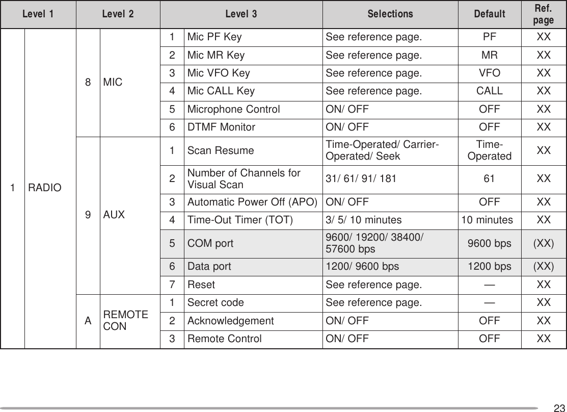
![70SPEAKER MUTEWhile programming the control band (not TX band), youmay not want to hear audio received on that band. Usethis function to mute the speaker allocated to the controlband.Press [MUTE] to switch the function ON (or OFF).• “MUTE” appears when the function is ON.SWITCHING TX DEVIATION (TM-D700E ONLY)This transceiver is capable of switching between wideand narrow deviations to transmit. After selecting thedesired band, access Menu 1–3–7 (WIDE/NARROW)and switch between Wide (default) and Narrow.• When Narrow is selected, “N” appears beside thefrequency.Note: Do not select Narrow for the band to be used for transmittingpackets.CHANGING SPEAKER CONFIGURATIONSThis transceiver has two speaker jacks. You can enjoy avariety of speaker configurations by using one or twoexternal speakers. Access Menu 1–2–3 (SPEAKER)and select mode 1 (default) or 2, depending on how theinternal and/or external speakers should function.noitcennoC edoM AdnaB BdnaBkcaj1PSylnO nahtiwdetcennoc rekaepslanretxeAedoMlanretxElanretxEBedoMlanretxElanretxEkcaj2PSylnO nahtiwdetcennoc rekaepslanretxeAedoMlanretnIlanretxEBedoMlanretxElanretnI2PSdna1PShtoB detcennocskcaj lanretxehtiw srekaepsAedoM1lanretxE2lanretxEBedoM2lanretxE1lanretxE](https://usermanual.wiki/JVC-KENWOOD/28451110/User-Guide-59321-Page-72.png)
![71MICROPHONE CONTROL (U.S.A./ CANADA ONLY)You can change numerous transceiver settings byoperating the Mic DTMF keys. To activate this function,access Menu 1–8–5 (MIC CONTROL) and select “ON”.The following table shows what function is switched ONand OFF or which setting is changed, by pressing theDTMF keys.1Transceivers equipped with the optional VS-3 unit announcethe displayed information {page XX}.2After entering the selection mode, press [ ] or [#] to changethe level or selection.3Both Volume Change and Squelch Adjustment cannot beactivated at the same time.4Both Volume Change and Squelch Adjustment must be OFFto change the tone or frequency step using this key.You can also make the following settings by pressing [D]first (ex. [D], then [2]).1After entering the selection mode, press [ ] or [#] to changethe level or selection.First press [2] to activate the Tone or CTCSS function.Press [OK] on the front panel of the transceiver to completethe setting.Note:◆Audible DTMF tones from other transceivers near you may be pickedup by your MC-53DM microphone. If so, this could prevent thefunction from working correctly.◆U.S.A. Only: It is illegal to transmit control codes on the VHF band.Transmit control codes only on the UHF band.1nacSlausiV9tnemtsujdAhcleuqS3,22SSCTC/enoT0egnahCrewoPXT3esreveRAretnE4egnahCpetSzHM1BegnahCleveLremmiD5rotinoMC—6tuodaeRycneuqerF speeByb1D]F[ yek7egnahCemuloV3,2nwoD48etuMrekaepS#pU42tceleSenoT18tceleSdnab-buS3tceleSnoitceriDtesffOCretaepeR5kcoLdapyeKFMTDDedoMnoitcnuf-itluM lecnaC6kcolnUdapyeKFMTDENWOD7tceleSB/AdnaBFPU](https://usermanual.wiki/JVC-KENWOOD/28451110/User-Guide-59321-Page-73.png)
 to move the cursor to the next (or previous)digit.• You can also press Mic [0] to [9] in sequence to enter 3digits.](https://usermanual.wiki/JVC-KENWOOD/28451110/User-Guide-59321-Page-74.png)
![73To change the transmit/ receive frequency:([VFO] ➡ [ENTER] ➡ [0] ~ [9] (enter the necessarydigits) ➡ [ENTER]) or ([VFO] ➡ [UP]/ [DWN])To recall a memory channel:([MR] ➡ [ENTER] ➡ [0] ~ [9] (enter the necessarydigits) ➡ [ENTER]) or ([MR] ➡ [UP]/ [DWN])To change the tone (or CTCSS) frequency:([TONE SEL] ➡ [0] ~ [9] (enter 2 digits; ex. [0], [5]) ➡[TONE SEL])• Use Nos. 01 to 38 shown in the table in page XX.• First activate the Tone or CTCSS function. You can select aseparate tone frequency for the Tone and CTCSS functions.Note: When in Remote Control mode, you can perform only the followingoperations on the mobile transceiver.•Transmit•Answer Back ON/ OFF•Secret Number Change•Partial/ Full Reset5Select the receive frequency on band B (UHF).• Mate this frequency with the transmit frequency on thehandy transceiver.6Select band A (VHF) as the TX band or Control band{page XX}.7To cause the mobile to send a controlacknowledgment to the handy transceiver, accessMenu 1–A–2 (ANSWER BACK) and select “ON”.• DTMF tones which represent the secret number will beused as an acknowledgment.8Access Menu 1–A–3 (CONTROL) and select “ON”.• “REMOTE CON” and “LOCK” appear when thetransceiver enters Remote Control mode.CONTROL OPERATIONWhen in Remote Control mode, the DTMF keys of thehandy transceiver will function as shown in the table.Each time you press the desired key, the handytransceiver will automatically enter transmit mode andsend the corresponding command to the mobiletransceiver.1NOSCD9RM2NOENOT0WOL3NOSSCTCARETNE4FFOSCDB LESENOT5FFOENOTC NORETAEPER6FFOSSCTCD FFORETAEPER7LLACE NWOD8OFVFPU](https://usermanual.wiki/JVC-KENWOOD/28451110/User-Guide-59321-Page-75.png)
![76PREPARATION FLOWThe following steps should guide you to a good start ofSky Command operation. First connect the Transporterto the HF transceiver {page XX}.yOn the Commanderand TransporteruOn the CommanderiOn the TransporterAccess Menu 4–3 and selectthe tone frequency {page XX}.• Select the same tone frequencyon both transceivers.• For the selectable frequencies,see the table given on page XX.Access Menu 4–4 and select“COMMANDER”.• “PUSH [ 0 ] KEY TO STARTCOMMANDER!!” appears.Access Menu 4–4 and select“TRANSPORTER”.• “TRANSPORTER” appears.Select the same VHF and UHFfrequencies.Access Menu 4–1 to programa call sign (9 digits max.) forthe Commander {page XX}.• You may enter your exact callsign; ex. WD6BQD.Access Menu 4–1 to programthe same call sign as youentered in step w {page XX}.Access Menu 4–2 to programthe same call sign as youentered in step e {page XX}.qOn the Commanderand TransportereOn the CommanderwOn the CommanderrOn the TransportertOn the TransporterAccess Menu 4–2 to programa call sign (9 digits max.) forthe Transporter {page XX}.• This call sign must be differentfrom the one for theCommander. So you may addSSID characters; ex.WD6BQD-1.Now the Commander and Transporter are in SkyCommand mode. For operations in this mode, see“CONTROL OPERATION” on page XX. First switch ONthe HF transceiver and press [SYNC] on theCommander. To exit the Sky Command mode, accessMenu 4–4 and select “OFF”.Note:◆Unless you program call signs, you cannot select “COMMANDER” or“TRANSPORTER” using Menu 4–4.◆On the HF transceiver, select 9600 bps and 1 stop bit (default) usingthe Menu Set-up function.◆Adjust the audio level on both the Transporter and HF transceiver.◆To distinguish your various stations or nodes, you can have up to 15Secondary Station IDentifiers (SSIDs); ex. WD6BQD-1 to WD6BQD-15. You always have to put a dash between your call sign and SSIDnumber.](https://usermanual.wiki/JVC-KENWOOD/28451110/User-Guide-59321-Page-78.png)
![77PROGRAMMING CALL SIGNSThe built-in TNCs of the Commander and Transportercommunicate each other when you send a controlcommand from the Commander. So you must programdifferent call signs (9 digits max.) on these transceiversas the IDs of the TNCs.Use the following Menu Nos. to program call signs:1Press [MENU] to enter Menu mode.2Press [4], [1] to select “4–1 (CMD CALLSIGN)”, or[4], [2] to select “4–2 (TRP CALLSIGN)”, then press[OK].• The callsign entry field appears; the first digit blinks.3Press [UP]/ [DWN] to select a character.• You can enter 0 to 9, A to Z, and –.4Press [->].• The cursor moves to the next digit.5Repeat steps 3 and 4 to enter up to 9 digits.6Press [OK] to complete the setting.7Press [MENU] to exit Menu mode.The keypad on the MC-53DM also is available to enteralphanumeric characters in step 3. See page XX.PROGRAMMING A TONE FREQUENCYOn receiving a tone from the Commander, theTransporter causes the HF transceiver to enter Transmitmode. On both the Commander and Transporter,access Menu 4–3 (TONE FREQUENCY) and select thedesired, same tone frequency.rednammoCnO1–4NGISLLACDMCrednammoCrofngisllaC2–4NGISLLACPRTretropsnarTrofngisllaCretropsnarTnO1–4NGISLLACDMCrednammoCrofngisllaC2–4NGISLLACPRTretropsnarTrofngisllaCKCAB afoyrtneslecnaC .ngisllac LED tatigidehtseteleD sirosrucehthcihw .gniknilb-< rosrucehtsesuaC .drawkcabevomot SNI taecapsastresnI sirosrucehthcihw .gniknilbRLC tsrifehtotrosrucehtskcabdnastigidllasraelC .tigid](https://usermanual.wiki/JVC-KENWOOD/28451110/User-Guide-59321-Page-79.png)
![781“FS” appears when you select 1 kHz step (LSB/ USB/ CW) or10 kHz step (FM/AM).2After pressing Mic [#], press Mic [0] to [9] to enter afrequency or memory channel number.CONTROL OPERATIONWhen in the Sky Command mode, the Mic keys of theCommander will function as below. First switch ON theHF transceiver and press Mic [0] on the Commander.Each time you press the desired key, the Commanderwill automatically enter transmit mode and send thecorresponding control command to the Transporter.FHehtFFO/NOhctiwsoT reviecsnart ciMsserP ]1[ .roycneuqerfehtegnahcoT FHehtnolennahcyromem reviecsnart ciMsserP ]PU[ /]NWD[ .FHanooiduatimsnartoT ycneuqerfciMdlohdnasserP ]TTP[ ,ehtotnikaepsneht .enohporcimFHanooiduaevieceroT ycneuqerf ciMsserP ]2[ .dnabFHUehtrotinomoT rednammoCehtnoFPciMehtdlohdnasserP rotinoMehtdengissayek .noitcnufyeKciM noitcnuF1FFO/NOrewoP2FFO/NOeviecerycneuqerfFH3hctiwsedomnoitaludoM4FFO/NOTIR5FFO/NOTIX6raelctesffoTIXrotesffoTIR7FFO/NOycneuqerf-tilpS8OFVotyromeMmorfrefsnarT9hctiwsBOFV/AOFV:edomOFVnI egnahcon:edomllaceRyromeMnI0FHmorf(eveirtersgnittestnerruC )reviecsnartBhctiwsedomllaceRyromeM/OFVCesaercniycneuqerftesffoTIRDesaercedycneuqerftesffoTIX1zHk1/zH01:edomWCro,BSU,BSLnI hctiws hctiwszHk01/zHk1:edomMAroMFnI#2NOyrtneycneuqerf:edomOFVnI rebmunlennahc:edomllaceRyromeMnI NOyrtne](https://usermanual.wiki/JVC-KENWOOD/28451110/User-Guide-59321-Page-80.png)
![79When Mic [0] is pressed, the Commander shows thecurrent settings of the HF transceiver as below:qHF frequencywVFO: A, VFO: B,00 ~ 99 (memory channel number)eRIT, XITrOFF, –9.99 ~ +9.99t“FS” appears when Mic [ ] is pressed.yLSB, USB, CW, FM, or AMuSPLIT–A: VFO A is used for transmitting.SPLIT–B: VFO B is used for transmitting.SPLIT–M: A memory channel is used for transmitting.Note:◆After pressing [MENU], you can access only Menu 4–4.◆The Transporter will transmit its call sign in Morse every 10 minutes,using the 144 MHz band.◆The APO timer does not operate on the transceiver with TransporterON.](https://usermanual.wiki/JVC-KENWOOD/28451110/User-Guide-59321-Page-81.png)
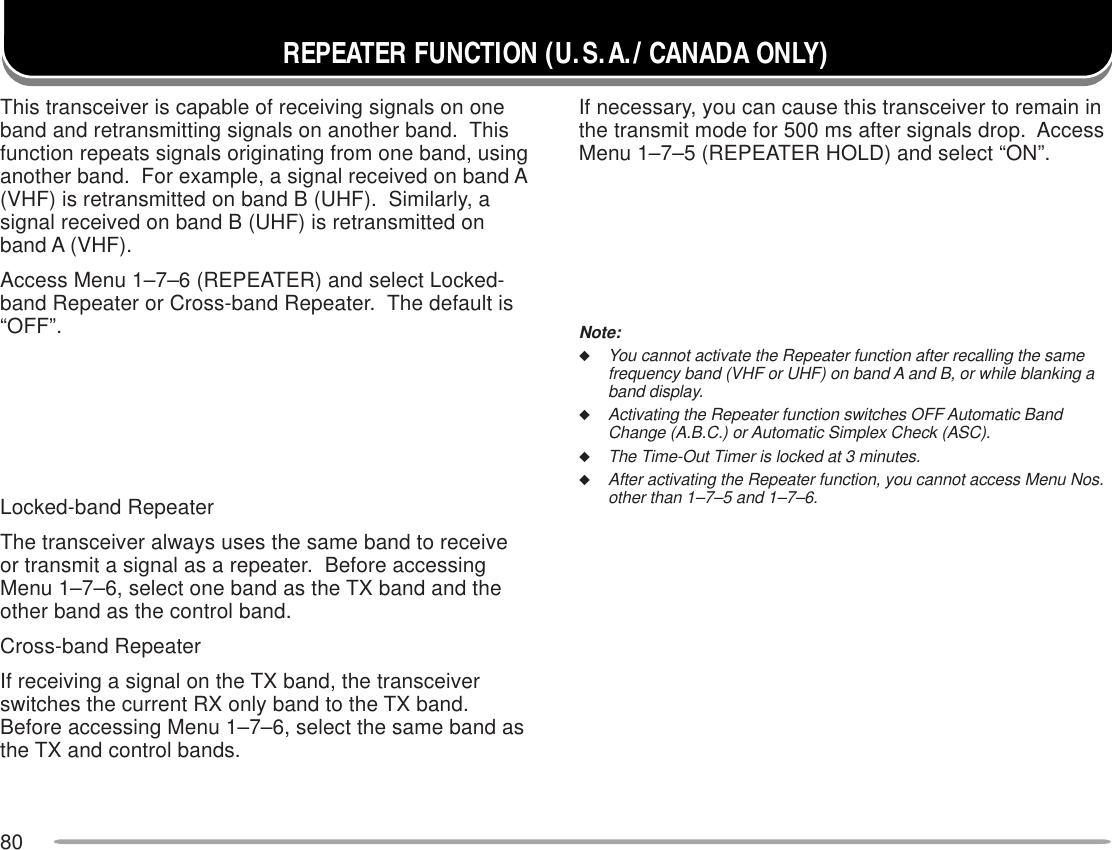
![81Install the optional VS-3 unit to use this function{page XX}. Each time you change the transceiver mode,such as VFO or Memory Recall, the transceiverautomatically announces the new mode.The table below shows what the transceiverautomatically announces when it enters a new mode.1When pressed in Memory Recall mode, the transceiverannounces the channel number, “channel”, and thefrequency2When pressed in VFO or Memory Recall mode.Note:◆To deactivate the Voice Synthesizer function after installing theoptional VS-3 unit, access Menu 1–2–4 (VOICE) and select OFF.◆While using Transceiver Lock, the transceiver makes anannouncement only when pressing Mic [6] in Microphone Controlmode or the PF key programmed with Voice. When in All-controlLock mode, pressing these keys simply causes an error beep tosound; the transceiver does not make an announcement in any case.◆The Voice Synthesizer function does not work while transmitting orscanning.VS-3 VOICE SYNTHESIZER (OPTIONAL)desserPyeK edoMweN tnemecnuonnA]OFV[ OFV”OFV“]RM[ llaceRyromeM”RM“]LLAC[ lennahCllaC”llaC“]MP[ elbammargorP yromeM ”MP“]UNM[ uneM”uneM“]LESDNAB[ lortnoC/XTweN dnab tnerruC ycneuqerf1yekFPciM htiwdemmargorp }XXegap{retnE2tceriDdapyeK yrtnE ”retnE“OFV dnabtnerrucehtnoycneuqerfOFV tigidzHM001ehthtiwgninnigeb )”tniop“:tnioplamicedzHM(llaceRyromeMehtdna,”lennahc“,rebmunlennahC ycneuqerf ,”pu“ro”wol“,slennahcUroLehtroF ycneuqerfehtdna,rebmunlennahcehtyalpsiDlennahC .”lennahc“dnarebmunlennahC ”pu“ro”wol“,slennahcUroLehtroF rebmunlennahcehtdnalennahCllaC llaceR ycneuqerfehtdna”llaC“llaceRMPrebmunlennahcehtdna”MP“uneM tnerrucdna(oNuneMehtdna”uneM“ )noitcelesSSCTC,.qerfenoT edocSCD,qerf tcelesSCDro,qerfSSCTC,.qerfenoTtnerruC edocYou can also press Mic [6] in Microphone Control mode{page XX} or the PF key programmed with Voice {pageXX}. The transceiver announces the displayedinformation as follows depending on the current mode.](https://usermanual.wiki/JVC-KENWOOD/28451110/User-Guide-59321-Page-83.png)