JVC KENWOOD 33101110 HF Transceiver with Scanning Receiver User Manual 0 Front page
JVC KENWOOD Corporation HF Transceiver with Scanning Receiver 0 Front page
Contents
- 1. Users Manual 1
- 2. Users Manual 2
Users Manual 1

© B62-1735-00 (K, E)
09 08 07 06 05 04 03 02 01 00
HF/ 50 MHz ALL MODE TRANSCEIVER
TS-480HX
TS-480SAT
INSTRUCTION MANUAL

ii
NOTICE TO THE USER
One or more of the following statements may be
applicable for this equipment.
FCC WARNING
This equipment generates or uses radio frequency energy.
Changes or modifications to this equipment may cause harmful
interference unless the modifications are expressly approved in
the instruction manual. The user could lose the authority to
operate this equipment if an unauthorized change or
modification is made.
INFORMATION TO THE DIGITAL DEVICE USER REQUIRED
BY THE FCC
This equipment has been tested and found to comply with the
limits for a Class B digital device, pursuant to Part 15 of the
FCC Rules. These limits are designed to provide reasonable
protection against harmful interference in a residential
installation.
This equipment generates, uses and can generate radio
frequency energy and, if not installed and used in accordance
with the instructions, may cause harmful interference to radio
communications. However, there is no guarantee that the
interference will not occur in a particular installation. If this
equipment does cause harmful interference to radio or
television reception, which can be determined by turning the
equipment off and on, the user is encouraged to try to correct
the interference by one or more of the following measures:
•
Reorient or relocate the receiving antenna.
•
Increase the separation between the equipment and receiver.
•
Connect the equipment to an outlet on a circuit different from
that to which the receiver is connected.
•
Consult the dealer for technical assistance.
EUROPEAN CUSTOMERS
Amateur radio regulations vary from country to
country. Confirm your local amateur radio regulations
and requirements before operating the transceiver.
Depending on the size and type of vehicle, the
maximum transmission output power for the mobile
operation will vary. The maximum transmission
output power is usually specified by the car
manufacturer to avoid interference with other electric
devices used in the car. Consult your car
manufacturer and amateur radio equipment dealer for
the requirements and installation.

i
THANK YOU
THANK YOU
Thank you for choosing this KENWOOD TS-480SAT/
HX transceiver. It has been developed by a team of
engineers determined to continue the tradition of
excellence and innovation in KENWOOD
transceivers.
This transceiver features a Digital Signal Processing
(DSP) unit to process AF signals. By taking
maximum advantage of DSP technology, the
TS-480SAT/ HX transceiver gives you enhanced
interference reduction capabilities and improves the
quality of audio. You will notice the differences when
you fight QRM and QRN. As you learn how to use
this transceiver, you will also find that KENWOOD is
pursuing “user friendliness”. For example, each time
you change the Menu No. in Menu mode, you will see
scrolling messages on the display that tell you what
you are selecting.
Though user friendly, this transceiver is technically
sophisticated and some features may be new to you.
Consider this manual to be a personal tutorial from
the designers. Allow the manual to guide you through
the learning process now, then act as a reference in
the coming years.
FEATURES
• All mode operation from HF to 50 MHz amateur
radio band with DSP functions
• Separate Remote Control panel for mobile
operation
• Digital Signal Processing (DSP) unit
• Adjustable DSP filter frequencies
• A built-in Antenna Tuner for the HF/ 50 MHz band
(TS-480SAT)
• 200 watts output power (TS-480HX)
SUPPLIED ACCESSORIES
After carefully unpacking the transceiver, identify the
items listed in the table below. We recommend you
keep the box and packing materials in case you need
to repack the transceiver in the future.
yrosseccA rebmuNtraP
ytitnauQ
TAS084-ST XH084-ST
K E K E
enohporciMXX-8360-19T 1111
elbacrewopCDXX-9843-03E 1122
gulpNIDinim )elamnip-6( XX-4040-75E 1111
gulpNIDinim )elamnip-8( XX-5040-75E 1111
elbacraludoM )m411-JR( XX-8843-03E 1111
elbacraludoM )mc0211-JR( XX-0053-03E –1–1
)A52(esuFXX-1352-50F 1122
)A4(esuFXX-7204-60F 1111
rofteSwercS )A(stekcarb XX-5302-99N 1111
tekcarb-LXX-6070-92J 2222
redlohlenaPXX-3660-92J 1212
tekcarblenaP )elibom( XX-7070-92J 1111
tekcarblenaP )esab( XX-9040-90J 1111
ahtiwretlifeniL dnabgniniater XX-8041-97L –1–2
rofretlifeniL lenaP XX-7141-97L 1111
tekcarbelbatroPXX-5070-92J –1–1
eldnahgniyrraCXX-0240-10K –1–1
rofteswercS tekcarbelbatroP )B( XX-1402-99N –1–1
noitcurtsnI launaM
XX-5371-26B E1111
XX-0571-26B F–1–1
XX-2571-26B S–1–1
XX-6371-26B G–1–1
XX-1571-26B I–1–1
XX-3571-26B D–1–1
/citamehcS smargaiDkcolB XX-9160-25B XX-0260-25B 1–1–
dracytnarraW – 1111

ii
THANK YOU
MODELS COVERED BY THIS MANUAL
The models listed below are covered by this manual.
TS-480SAT: HF/ 50 MHz All mode Transceiver with
Automatic Antenna Tuner (100 watts
output)
TS-480HX : HF/ 50 MHz All mode Transceiver
(200 watts output)
MARKET CODES
K-type : The Americas
E-type : Europe/ General
The market code is shown on the carton box.
Refer to the specifications {page 92} for information
on the available operating frequencies.
WRITING CONVENTIONS FOLLOWED
The writing conventions described below have been
followed to simplify instructions and avoid
unnecessary repetition.
noitcurtsnI oDottahW
sserP ]YEK[ .esaelerdnasserP YEK .
sserP ]1YEK[ ,]2YEK[ .sserP 1YEK esaeler,yliratnemom
1YEK sserpneht, 2YEK .
sserP ]YEK[)s1( .dlohdnasserP YEK arofnwod esaelernehtdnadnoces YEK .
sserP ]2YEK[+]1YEK[ .
dlohdnasserP 1YEK neht,nwod
sserp 2YEK eromeraerehtfI. dlohdnasserp,syekowtnaht ehtlitnunrutniyekhcaenwod .desserpneebsahyeklanif
sserP ][+]YEK[ .
sserp,FFOreviecsnartehthtiW dlohdna YEK NOhctiwsneht, gnisserpybrewopreviecsnarteht ][ .)REWOP(
iii
PRECAUTIONS
Please observe the following precautions to prevent
fire, personal injury, and transceiver damage:
• Connect the transceiver only to a power source
described in this manual or as marked on the
transceiver itself.
• Route all power cables safely. Ensure the power
cables can neither be stepped upon nor pinched
by items placed near or against the cables. Pay
particular attention to locations near AC
receptacles, AC outlet strips, and points of entry to
the transceiver.
• Take care not to drop objects or spill liquid into the
transceiver through enclosure openings. Metal
objects, such as hairpins or needles, inserted into
the transceiver may contact voltages resulting in
serious electrical shocks. Never permit children to
insert any objects into the transceiver.
• Do not attempt to defeat methods used for
grounding and electrical polarization in the
transceiver, particularly involving the power input
cable.
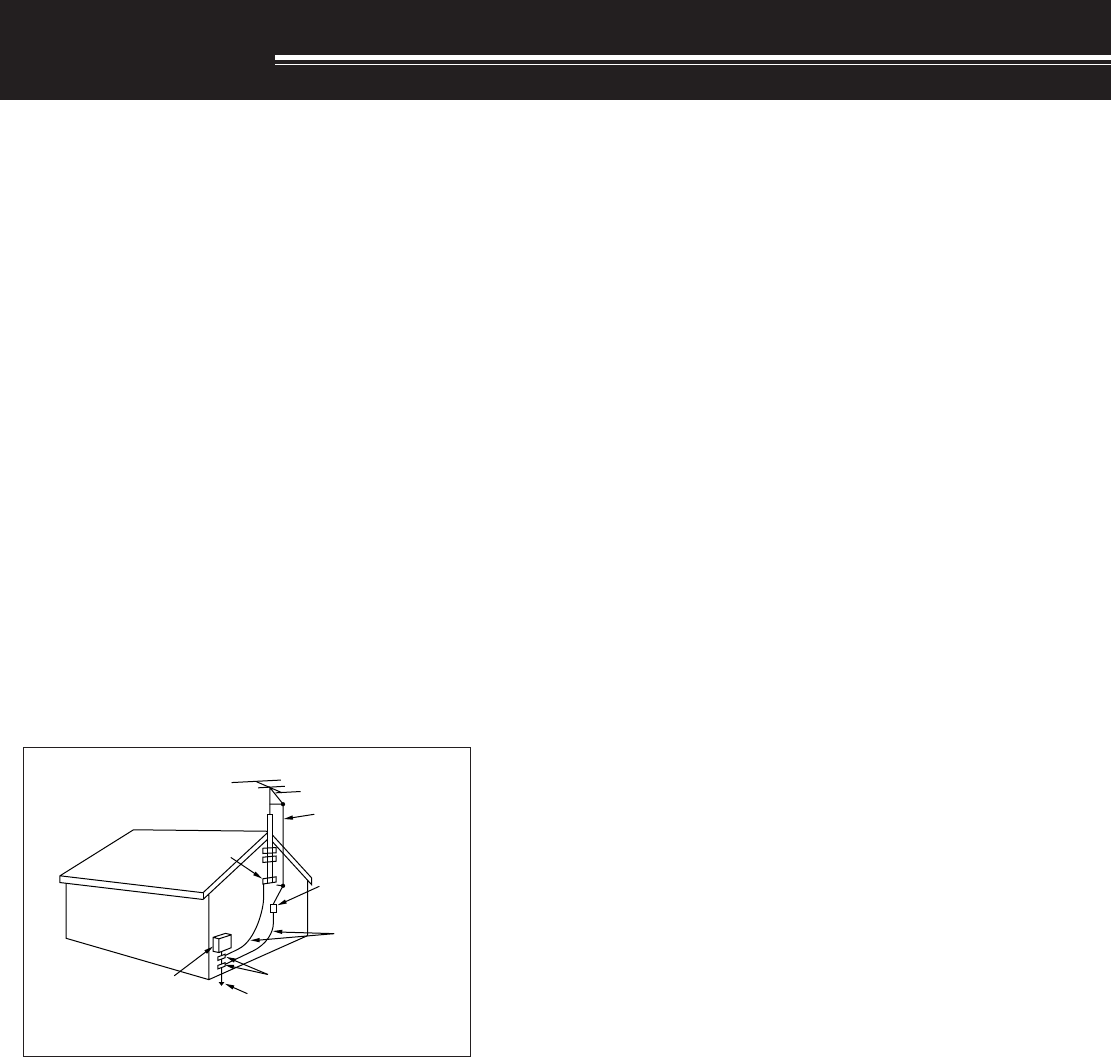
• Adequately ground all outdoor antennas for this
transceiver using approved methods. Grounding
helps protect against voltage surges caused by
lightning. It also reduces the chance of a build-up
of static charge.
EXAMPLE OF ANTENNA GROUNDING
ANTENNA
LEAD IN
WIRE
GROUND
CLAMP
ELECTRIC SERVICE
EQUIPMENT
ANTENNA
DISCHARGE UNIT
GROUNDING
CONDUCTORS
GROUND CLAMPS
POWER SERVICE
GROUNDING ELECTRODE
SYSTEM
• Minimum recommended distance for an outdoor
antenna from power lines is one and one-half
times the vertical height of the associated antenna
support structure. This distance allows adequate
clearance from the power lines if the support
structure fails for any reason.
• Locate the transceiver so as not to interfere with
its ventilation. Do not place books or other
equipment on the transceiver that may impede the
free movement of air. Allow a minimum of
10 cm (4 inches) between the rear of the
transceiver and the wall or operating desk shelf.
• Do not use the transceiver near water or sources
of moisture. For example, avoid use near a
bathtub, sink, swimming pool, or in a damp
basement or attic.
• The presence of an unusual odor or smoke is
often a sign of trouble. Immediately turn the
power OFF and remove the power cable. Contact
a KENWOOD service station or your dealer for
advice.
• Locate the transceiver away from heat sources
such as a radiator, stove, amplifier or other
devices that produce substantial amounts of heat.
• Do not use volatile solvents such as alcohol, paint
thinner, gasoline or benzene to clean the cabinet
of the transceiver. Use a clean cloth with warm
water or a mild detergent.
• Disconnect the input power cable from the power
source when the transceiver is not used for long
periods of time.
• Remove the transceiver’s enclosure only to do
accessory installations described in this manual or
accessory manuals. Follow provided instructions
carefully, to avoid electrical shocks. If unfamiliar
with this type of work, seek assistance from an
experienced individual, or have a professional
technician do the task.
• Enlist the services of qualified personnel in the
following cases:
a) The power supply or plug is damaged.
b) Objects have fallen or liquid has spilled into the
transceiver.
c) The transceiver has been exposed to rain.
d) The transceiver is operating abnormally or
performance has seriously degraded.
e) The transceiver has been dropped or the
enclosure damaged.
• Do not attempt to perform any kind of
configuration or menu setup configuration while
driving your car.
• Do not wear headphones while driving.
• Install the transceiver in a safe and convenient
position inside of your vehicle so as not to subject
yourself to danger while driving. Consult your car
dealer for the transceiver installation to ensure
safety.
• HF/ 50 MHz mobile antennas are larger and
heavier than VHF/ UHF antennas. Therefore, use
a strong and rigid mount to safety and securely
install the HF/ 50 MHz mobile antenna.
1
INSTALLATION
MOBILE INSTALLATION
When you use this transceiver for mobile operation, do not attempt to perform any kind of configuration or menu
setup configuration while driving your car; it is simply too dangeous. Stop the car and then perform transceiver
configuration. In addition, do not wear headphones while driving.
You should install the transceiver in a safe and convenient position inside your vehicle so as not to subject
yourself to danger while driving. For example, install the transceiver under the dash in front of the passenger seat
so that knees or legs will not strike the transceiver if you brake suddenly. Additionally, do not install the
transceiver and its accessories on to the air bag lids. We recommend you consult your car dealer for the
transceiver installation to ensure safety.
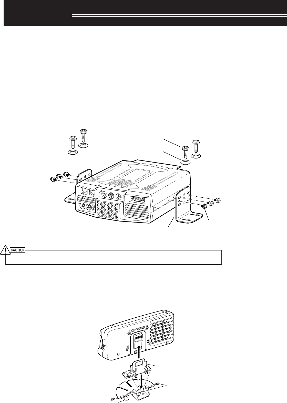
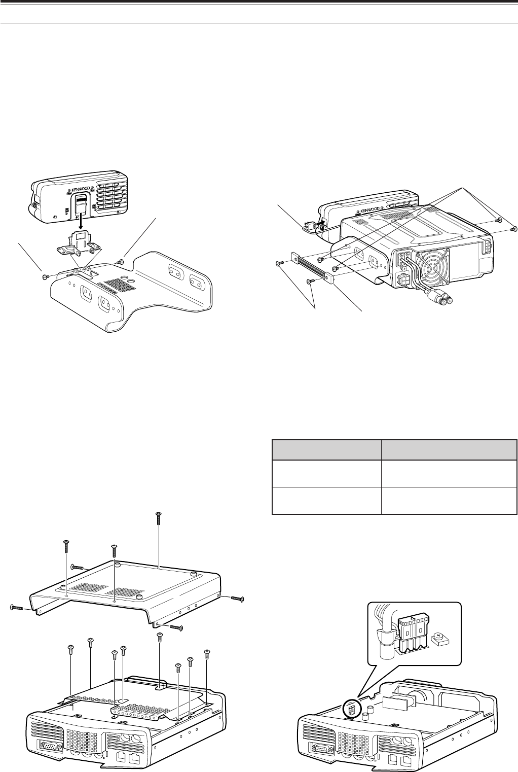
INSTALLATION EXAMPLE
1Attach the 2 L-brackets using the 6 supplied SEMS screws (M4 x 10 mm) as shown below.
2Position the transceiver in the mounting bracket and tighten the 4 supplied tapping screws (5 mm x 16 mm) to
fix the transceiver in place.
Do not install the TX/ RX unit in non-ventilated areas. Air must flow through the TX/ RX unit to keep the unit cooled.
REMOTE CONTROL PANEL INSTALLATION
1Assemble the Remote Control panel holder with the fan-shaped base with 2 supplied SEMS screws.
2Peel off the adhesive tape cover from the bottom of the base.
3Afix the panel to the vehicle with 2 tapping screws.
PADDLE KEY
EXT.SP DATA REMOTE
COM
MIC PANEL
SEMS screw
(M4 x 10 mm)
Tapping screw
(5 mm x 16 mm)
Flat washer
(5 mm)
L-bracket
Remote Control
panel holder
SEMS screws
(M4 x 10 mm)
Adhesive tape cover
2
1 INSTALLATION
ANTENNA CONNECTION
In general, HF/ 50 MHz mobile antennas are larger and heavier than VHF/ UHF antennas. Therefore, use a
strong and rigid mount to safety and securely install the HF/ 50 MHz mobile antenna.
A bumper mount is recommended for stable mounting. However, most recent models of vehicles have plastic
bumpers. For such vehicles, ground the antenna mount to the body chassis with a large wire. Antenna
installation is critical for successful mobile operation. For further information, refer to The Radio Amateur’s
Handbook, Radio Handbook, or other published texts.
GROUND CONNECTION
The ground, which is the other half of the antenna system, is very important when using a mobile whip type
antenna. Connect the feed line ground for the antenna securely to the vehicle’s chassis, and be certain to bond
(electrically connect) the vehicle’s body to chassis. The sheet metal will provide the primary ground plane, so be
sure to establish a good RF connection from the feed line to both the chassis and the body. For comprehensive
information on mobile antennas installations and optimization, refer to the ARRL Handbook or similar publications.
IGNITION NOISE
This transceiver has been equipped with a Noise Blanker and Digital Noise Limitter to filter ignition noises out.
However, some cars may generate excessive ignition noise. If there is excessive noise, use suppressor spark
plugs (with resisters), and/ or DC line filters to reduce the electric noises. The ARRL Handbook, or similar
refereneces, has a wealth of information regarding this topic.
Note:
◆
After installation and wiring are completed, confirm that all work has been done correctly, then connect the DC power cable plug(s) to the
transceiver.
◆
If the fuse blows, disconnect the DC power cable plug(s) from the transceiver immediately, then check all the DC power cables to find the
reasons of the short circuit. The DC cable may be damaged, short circuited, pinched, or squashed. After resolving the problem, replace the
fuse with one of the same type and rating.
◆
Do not remove the fuse holder for any reason.
DC
13.8V
1
DC 2 13.8V
AT
GNDGND
221
12 V battery
DC IN
Red (+)
Black (—)
Passenger
Compartment
Engine compartment
Place the DC cable the wall of the engine compartment
securely. Avoid applying excessive heat, vapor and water to
the cable.
Use a rubber or plastic grommet so that the cable
does not directly touch the vehicle chassis.
Body
DCDC
13.8V
1
DC 2 13.8V
AT
GNDGND
21
DC IN 1 DC IN 2
Place the DC cable the wall of the engine compartment
securely. Avoid applying excessive heat, vapor and water to
the cable.
Engine compartment
Passenger
Compartment
Body
Use a rubber or plastic grommet so that the cable
does not directly touch the vehicle chassis.
Red (+)
Black (–)
12 V battery
DC POWER CABLE CONNECTION
Connect the DC power cable directly to the vehicle’s
battery terminals using the shortest route. Do not use
the cigarette lighter socket! The current rating of the
cigarette lighter socket is too small to operate the
transceiver. Ensure to use a 12 V vehicle battery
which has sufficient current capacity. If the current is
insufficient, the display may darken during
transmission or the trasceiver may work
intermittiently. If you use the transceiver for a long
period when the vehicle battery has not been fully
charged or when the engine has been stopped, the
battery may become discharged in a short time and
will not have sufficient reserves to start the engine.
Avoid using the transceiver under these conditions.
Keep in mind that the TS-480SAT transceiver draws a
peak current of approximately 20.5 A and the
TS-480HX transceiver draws a peak current of
approximately 41 A during transmission.
Note:
◆
Do not use two separate batteries to connect each DC cables
from the transceiver (TS-480HX). The DC voltage difference
between DC IN 1 and DC IN 2 connectors at the transceiver must
be within DC 1.0 V to operate the transceiver.
◆
Do not use two different type of the cables. Using different length
and/ or different gauged cable could result in a voltage difference
between DC IN 1 and DC IN 2 connectors at the transceiver.
TS-480SAT
TS-480HX
3
1 INSTALLATION
FIXED STATION INSTALLATION
When you use the transceiver at a fixed location, the transceiver requires 13.8 V DC power supply
(The TS-480HX requires 2 DC power supplies).
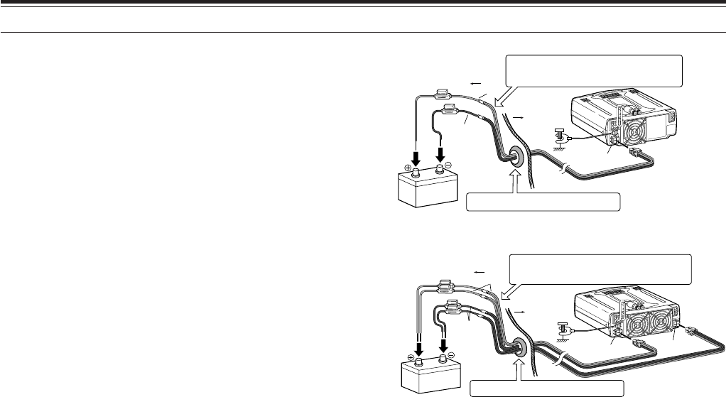
FRONT PANEL INSTALLATION
1Attach the oval-shaped base to the front panel mounting bracket using two SEMS screws (3 mm x 5 mm) as
shown below.
2Slide the Remote Control panel along the mounting bracket rails until secure.
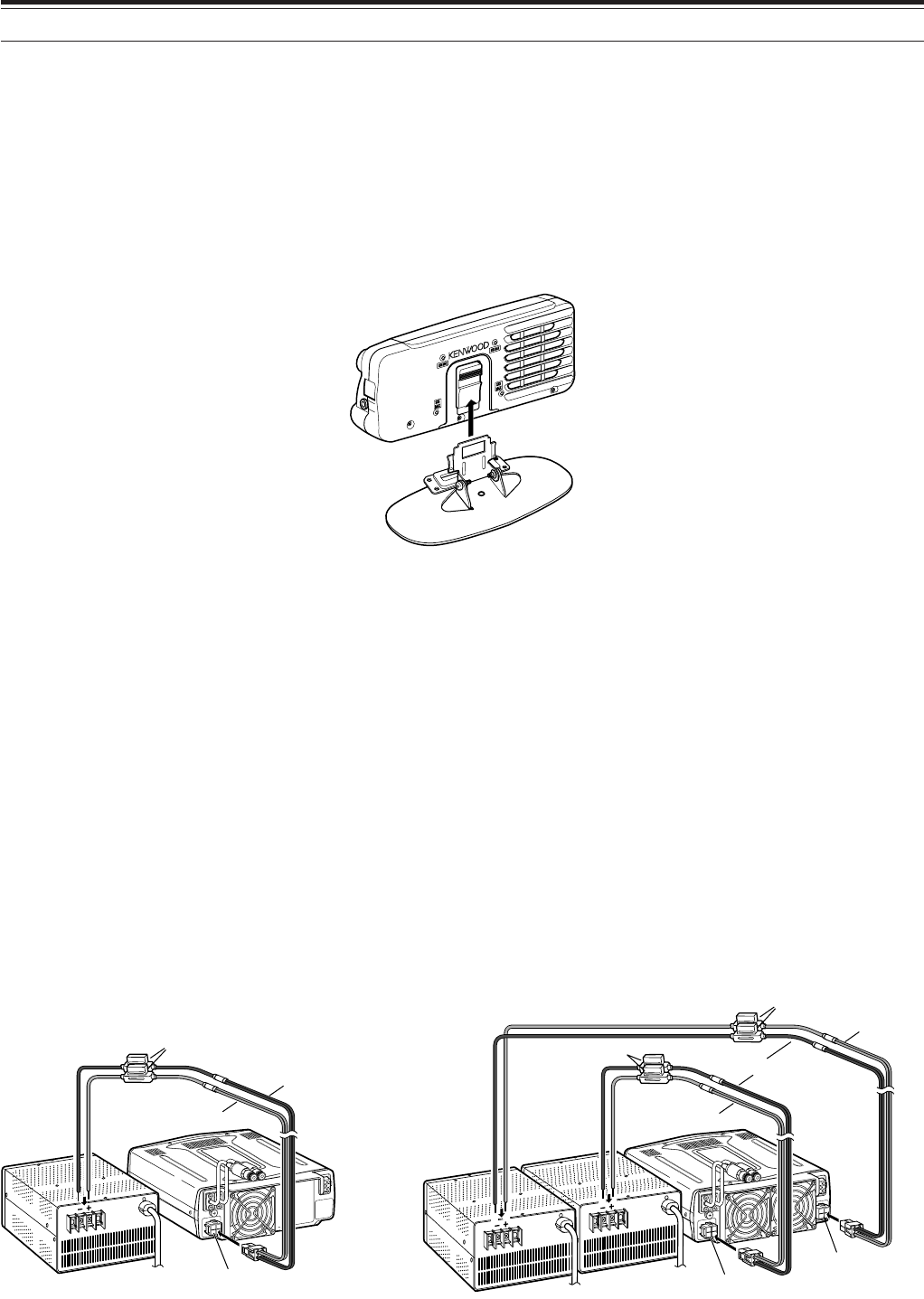
DC POWER SUPPLY CONNECTION
In order to use this transceiver, you need a separate 13.8 V DC power supply (two 13.8 V DC power supplies are
required to transmit for the TS-480HX) that must be purchased separately. Do not directly connect the transceiver
to an AC outlet. Use the supplied DC power cables to connect the transceiver to a regulated power supply. Do
not substitute a cable with smaller gauge wires. The current capacity of each power supply must be 20.5 A peak
or more.
1Connect the DC power cable(s) to the regulated DC power supply (two 13.8 V DC power supplies are used for
the TS-480HX); the red lead to the positive terminal and the black lead to the negative terminal.
2Connect the DC power cable to the transceiver’s DC power connector.
• Press the connectors firmly until the locking tab clicks.
Note:
◆
Before connecting the DC power supply to the transceiver, be sure to switch OFF the DC power supply and the transceiver.
◆
Do not plug the DC power supply into an AC outlet until you make all connections.
◆
When two power supplies are used for the TS-480HX, the DC voltage difference at the transceiver DC IN connectors must be within 1.0 V DC.
◆
Do not use different types (length and gauge) of DC cables to avoid voltage differences (TS-480HX).
DC
13.8V
1
DC 2 13.8V
AT
GNDGND
221
Black (—)
Red (+)
Fuse (25 A)
DC IN 1
DC 13.8 V
DC Power supply
(20.5 A or more)
DC
13.8V
1
DC 2 13.8V
AT
GNDGND
21
Black (–)
Red (+)
Fuse (25 A)
DC IN 1
DC 13.8 V
DC IN 2
DC 13.8 V
Red (+)
Fuse (25 A)
DC Power supply
(20.5 A or more)
DC Power supply
(20.5 A or more)
TS-480SAT TS-480HX

4
1 INSTALLATION
ANTENNA CONNECTION
An antenna system consists of an antenna, feed line, and ground. The transceiver can give excellent results if the
antenna system and its installation are given careful attention. Use a properly adjusted 50 Ω antenna of good
quality, a high-quality 50 Ω coaxial cable, and first-quality connectors. All connections must be clean and tight.
After making the connections, match the impedance of the coaxial cable and antenna so that the SWR is 1.5:1 or
less. High SWR will cause the transmit output to drop and may lead to radio frequency interference to consumer
products such as stereo receivers and televisions. You may even interfere with your own transceiver. Reports
that your signal is distorted could indicate that your antenna system is not efficiently radiating the transceiver’s
power.
Connect your primary HF/ 50 MHz antenna feed line to ANT 1 on the rear of the transceiver. If you are using two
HF/ 50 MHz antennas, connect the secondary antenna to ANT 2. Refer to page 16 for the location of the antenna
connectors.
Note:
◆
Transmitting without connecting an antenna or other matched load may damage the transceiver. Always connect the antenna to the
transceiver before transmitting.
◆
All fixed stations should be equipped with a lightning arrester to reduce the risk of fire, electric shock, and transceiver damage.
◆
The transceiver’s protection circuit will activate when the SWR is greater than 2.5:1; however, do not rely on protection to compensate for a
poorly functioning antenna system.
GROUND CONNECTION
At the minimum, a good DC ground is required to prevent such dangers as electric shock. For superior
communications results, a good RF ground is required against which the antenna system can operate. Both of
these conditions can be met by providing a good earth ground for your station. Bury one or more ground rods or
a large copper plate under the ground, then connect this to the transceiver GND terminal. Use heavy gauge wire
or a copper strap, cut as short as possible, for this connection. Do not use a gas pipe, an electrical conduit, or a
plastic water pipe as a ground.
LIGHTNING PROTECTION
Even in areas where lightning storms are less common, there are usually a limited number of storms each year.
Consider carefully how to protect your equipment and home from lightning. The installation of a lightning arrestor
is a start, but there is more that you can do. For example, terminate your antenna system transmission lines at an
entry panel that you install outside your home. Ground this entry panel to a good outside ground, then connect
the appropriate feed lines between the entry panel and your transceiver. When a lightning storm occurs,
disconnecting the feed lines from your transceiver will ensure additional protection.
5
1 INSTALLATION
PORTABLE BRACKET (E-TYPE ONLY)
Using the supplied Portable Bracket, you can carry the Remote Control panel and TX/ RX unit together.
Two TX/ RX unit positions are available. If you do not use the EXT.SP, REMOTE or DATA terminals, place the
transceiver in front position. If you use the EXT.SP, REMOTE or DATA terminals, place the TX/ RX unit to the
back position. You can also attach the handle as shown if necessary. Use the supplied short cable (RJ11/ 20 cm)
to connect the Remote Control panel and the TX/ RX unit.
FUSES
The following fuses are used in the TS-480SAT/ HX transceiver. If a fuse blows, determine the cause then correct
the problem. Only after the problem has been resolved, replace the blown fuse with a new one with the specified
ratings. If newly installed fuses continue to blow, disconnect the power plug and contact a KENWOOD service
center or your dealer for assistance.
noitacoLesuF gnitaRtnerruCesuF
XH/TAS084-ST )tinuXR/XT( A4
)renutannetnalanretxenaroF(
rewopCDdeilppuS elbac A52
SEMS screw
(M4 x 10 mm)
SEMS screw
(M4 x 10 mm)
DC
13.8V
1
DC 2 13.8V
AT
GNDGND
221
Binding head screw
(M4 x 8 mm)
Flat-head screw
(M4 x 12 mm)
RJ11/ 20 cm
Carrying handle
PANEL
MIC
PADDLE
KEY
EXT.SP DATA REMOTE
COM
PANEL
MIC
PADDLE
KEY
EXT.SP DATA REMOTE
COM
1 Remove 7 screws at the bottom of the TX/ RX unit.
2 Remove 8 screws inside of the TX/ RX unit.
3Lift the shield cover.
4Replace 4 A fuse.
6
1 INSTALLATION
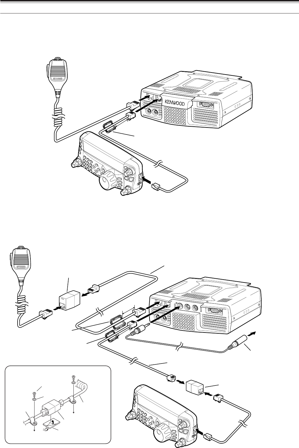
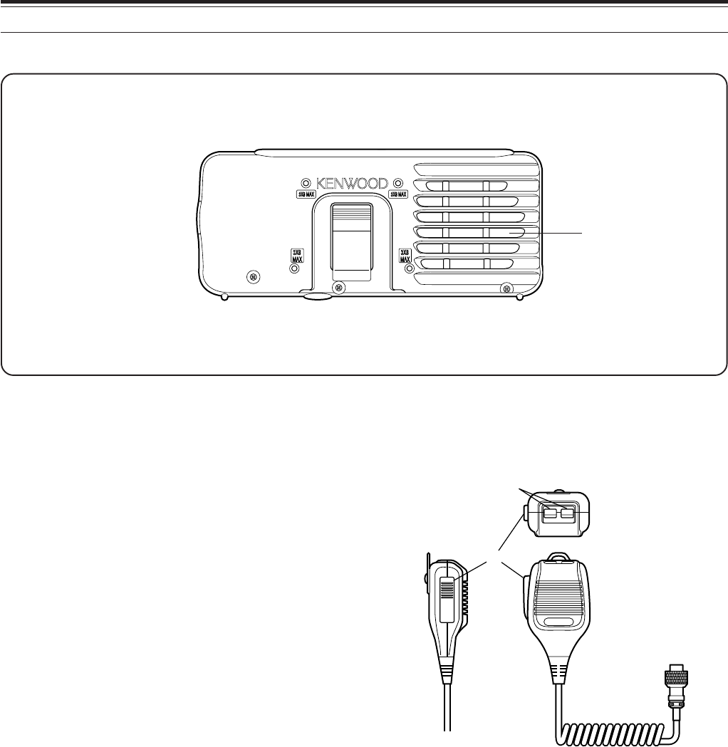
PANEL AND MICROPHONE CONNECTION
Plug the microphone plug to the MIC jack (8-wire/ RJ45), then connect the Remote Control panel to the TX/ RX
unit with the supplied cable (2 m/ 6-wire/ RJ11).
PADDLE KEY
EXT.SP DATA REMOTE
COM
MIC PANEL
Microphone
To PANEL
To MIC
3cm
Line filter
PANEL AND MICROPHONE CONNECTION USING PG-4Z (OPTION)
Use the cables and connectors to connect the Remote Control panel and TX/ RX unit with the PG-4Z cable kit as
shown below.
PADDLE KEY
EXT.SP DATA REMOTE
COM
MIC PANEL
To MIC
To EXT.SP
To external speaker
External speaker extension
cable from the PG-4Z cable
kit (when the external speaker
is used)
Extension adaptor (RJ11)
from the PG-4Z cable kit
Extension cable (RJ11)
from the PG-4Z cable kit
Extension adaptor (RJ45)
from the PG-4Z cable kit
Line filter (large) from
the PG-4Z cable kit
Extension cable (RJ45)
from the PG-4Z cable kit
Line filter (small) from
the PG-4Z cable kit
3 cm
3 cm
Tapping screw
(4 mm x 14 mm)
Flat washer
Microphone cable
Double-sided
adhesive tape
RJ45 (8-wire)
adaptor
Cable
holder
7
1 INSTALLATION
PADDLE KEY
EXT.SP DATA REMOTE
COM
MIC PANEL
+GND
GND dash dot
1234
Paddle Straight key
Bug key
Electric keyer
MCP CW output
Headphones
MJ-88
(Opt.)
External speaker (Opt.)
Microphone
w/ 8-pin metal plug
(Opt.)
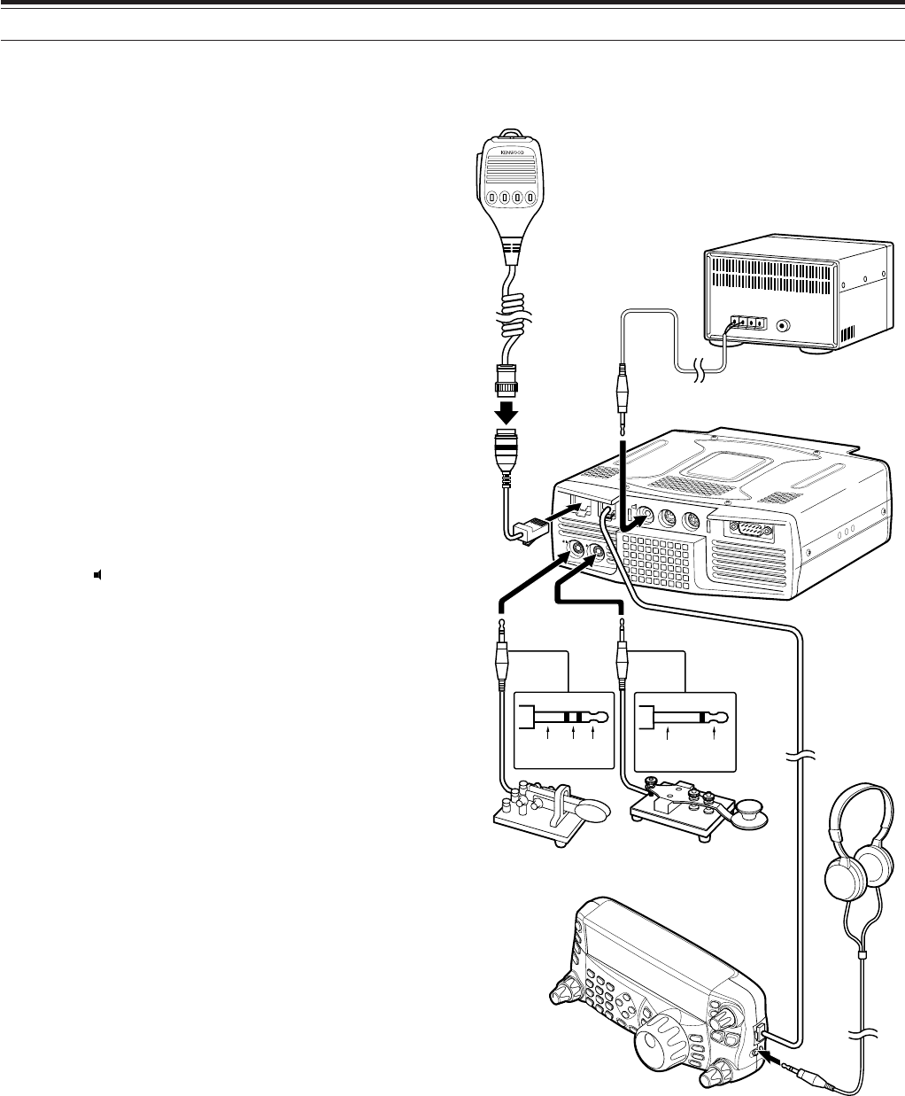
ACCESSORY CONNECTIONS
TX/ RX UNIT
■Microphone (MIC)
Connect a microphone having an impedance
between 250 and 600 Ω. As for the supplied
microphone, fully insert the modular connector into
the MIC jack until the locking tab clicks. You can
still utilize 8-pin metal type plug microphones,
such as MC-43S, MC-47, MC-52DM, MC-60A,
MC-80, MC-85, and MC-90 with the optional MJ-
88 adaptor (optional) if necessary. However, do
not use the MC-44, MC-44DM, MC-45, MC-45E,
MC-45DM, MC-45DME, or MC-53DM condensor-
type microphones.
■External Speaker (EXT.SP)
On the front panel of the TX/ RX unit, there is an
external speaker jack. If an external speaker is
connected to EXP.SP jack, the built-in speaker on
the back of the remote control panel will mute.
Use only external speakers with an impedance of
4 to 8 Ω (8 Ω nominal). The jacks accept only
3.5 mm (1/8") diameter, 2-conductor (mono) plugs.
• The “ ” projection indicates the external
speaker jack.
Note:
Do not connect headphones to this jack. The high audio
output of this jack could damage your hearing.
■Keys for CW (PADDLE and KEY)
For CW operation using the internal electronic
keyer, connect a keyer paddle to the PADDLE
jack. For CW operation without using the internal
electronic keyer, connect a straight key,
semi-automatic key (bug), electronic keyer, or the
CW keying output from a Multi-mode
Communications Processor (MCP) to the KEY
jack. The PADDLE and KEY jacks mate with a
3.5 mm (1/8") 3-conductor plug and a 3.5 mm
(1/8") 2-conductor plug respectively. External
electronic keyers or MCPs must have a positive
keying output to be compatible with this
transceiver. Use a shielded cable between the
key and the transceiver.
• The “•” projection indicates the key jack and
the “••” projection indicates the paddle jack.
Note:
Due to the functionality of the internal electronic keyer, you
may find it unnecessary to connect both a paddle and another
type of keyer unless you want to use a PC-based keyer for CW.
Refer to the “ELECTRONIC KEYER” section {page 39} to
become familiar with the internal keyer.
REMOTE CONTROL PANEL
■Headphones (PHONES)
Connect monaural or stereo headphones having a
4 to 32 Ω impedance. This jack accepts a
3.5 mm (1/8") diameter, 2-conductor (mono) or
3-conductor (stereo) plug. After connecting the
headphones, you will hear no sound from the
internal (or optional external) speaker.
8
YOUR FIRST QSO
Are you ready to give your TS-480SAT/ HX a quick
try? Reading these two pages should get your voice
on the air in your first QSO on the HF/ 50 MHz band
shortly. The instructions below are intended only for
a quick guide. If you encounter problems or there is
something you don’t understand, read the detailed
explanations given later in this manual.
Note:
This section explains only keys and controls required to
briefly try the transceiver.
qSet the following as specified:
•AF control: Fully counterclockwise
•SQL control: Fully counterclockwise
Then, switch ON the DC power supply if you are
using the DC power supply. If you are operating the
transceiver with the car batteries, ensure that the DC
power source(s) are available at the DC connector(s).
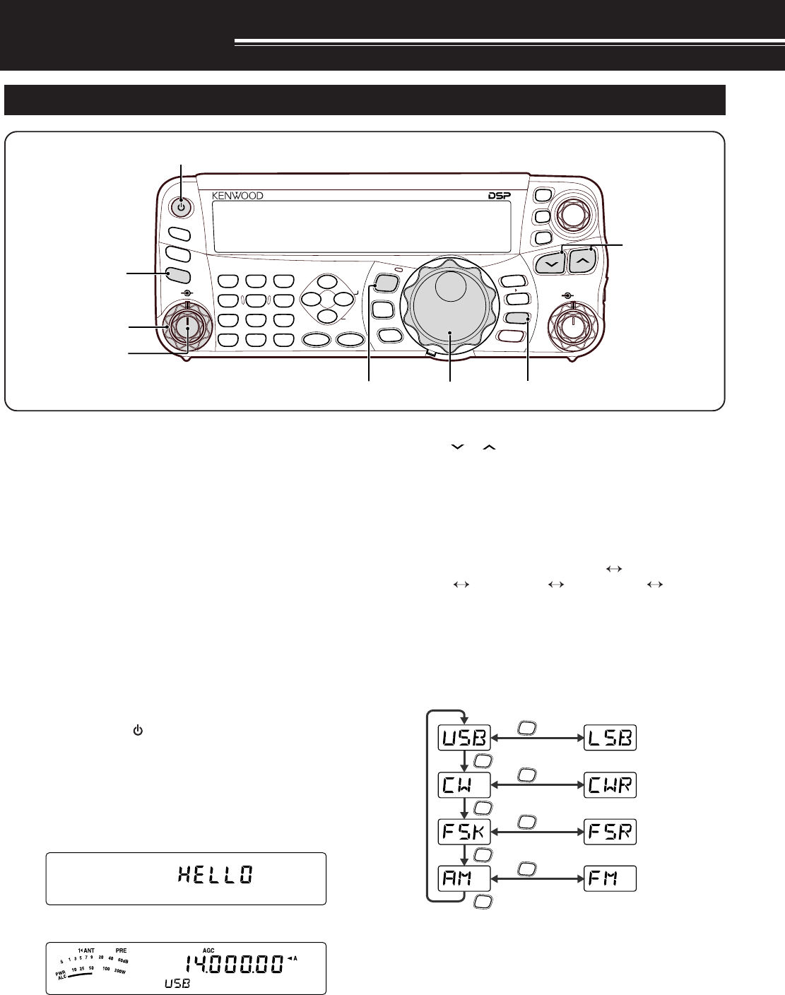
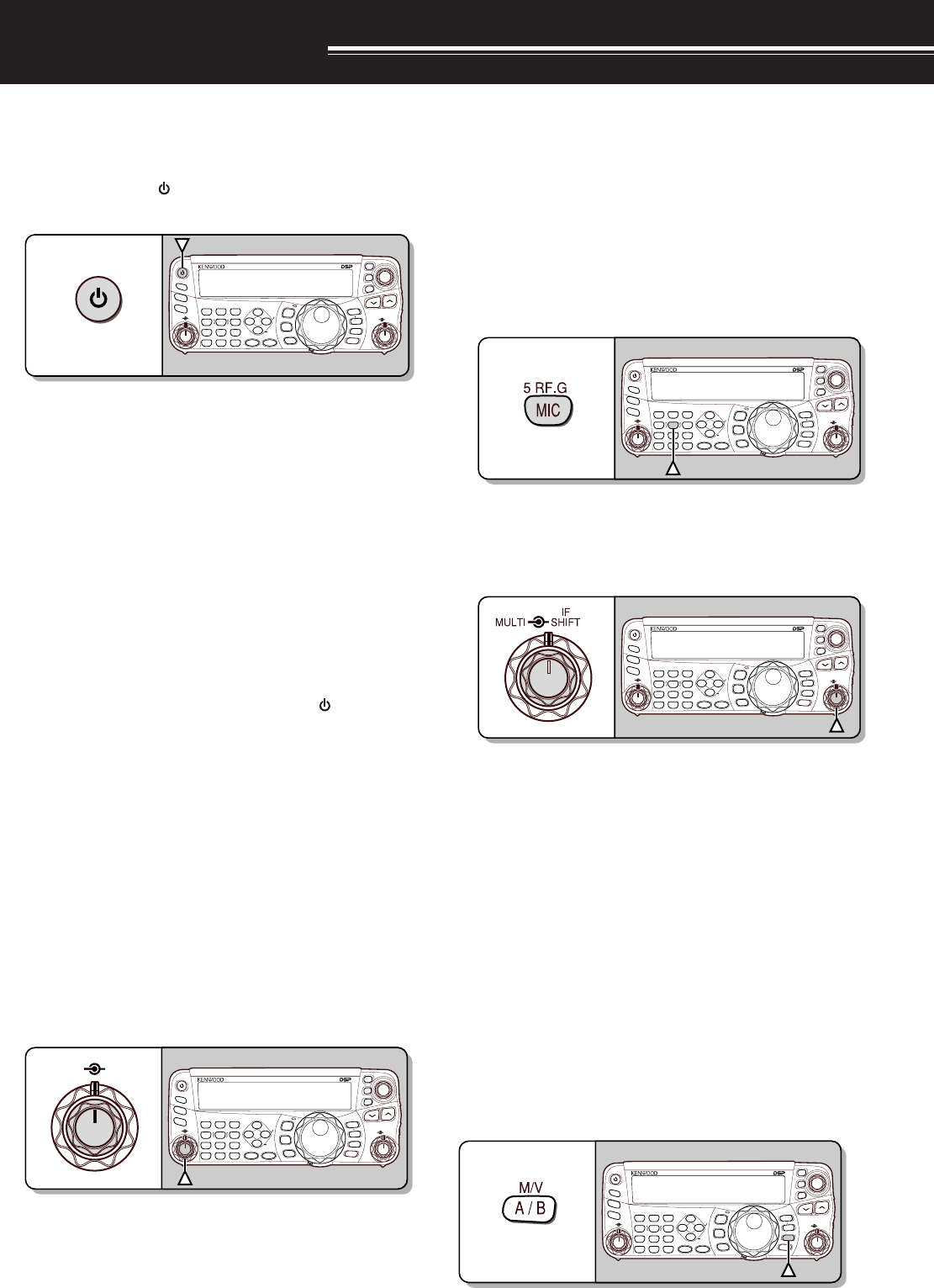
wPress and hold [ ] (POWER) briefly to turn ON
the transceiver.
• Do not press the switch for more than
approximately 2 seconds; the transceiver will
be switched OFF.
• Upon power up, “HELLO” appears, followed by
the selected frequency and other indicators.
d
eConfirm that VFO A has been selected for
communications; “
t
A” should be visible on the
display. If it has not, press [A/B / M/V] to select
VFO A.
rTurn the AF control slowly clockwise until you hear
a suitable level of background noise.
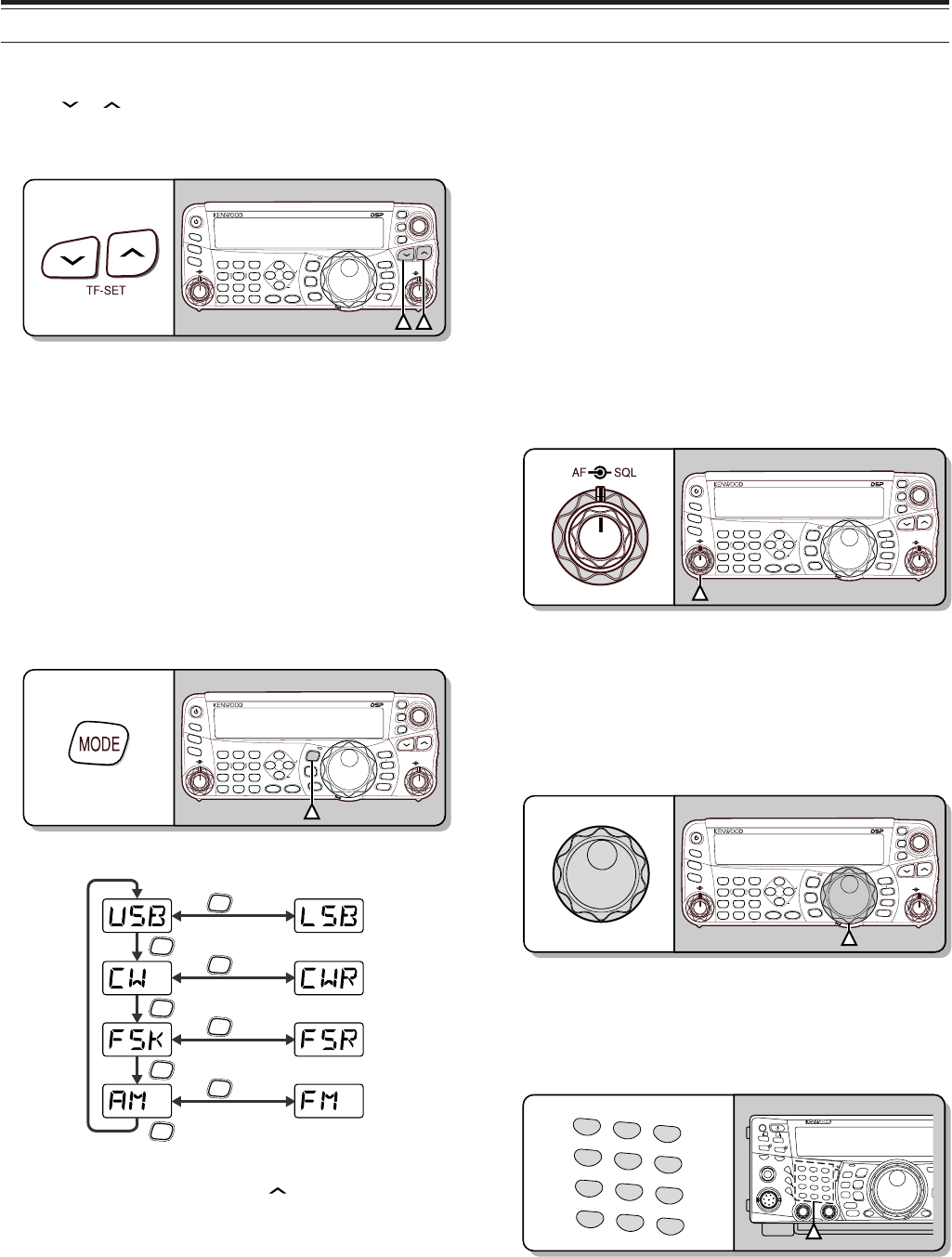
tPress [ ]/ [ ] to select a desired HF/ 50 MHz
Amateur radio band.
yPress [MODE] to select the desired
communication mode.
• There are 4 mode pairs: USB/ LSB, CW/ CWR
(Reversed pitch), FSK/ FSR (Reverse shift)
and AM/ FM. Press [MODE] (1 s) to toggle the
mode within each pair: USB LSB,
CW CWR, FSK FSR, or AM FM.
• To select the alternate mode on each operating
mode, press and hold the key for 1 second.
For example, if USB is selected, press
[MODE] (1 s) to switch to LSB mode. The
following diagram illustrates how to access
each mode.
MODE
MODE
MODE
MODE
MODE
(1 s)
MODE
(1 s)
MODE
(1 s)
MODE
(1 s)
uIf you have selected FM, turn the SQL control
clockwise until the background noise is just
eliminated; the green LED (above the [MODE]
key) turns OFF.
• With LSB or USB selected, skip this step.
iTurn the Tuning control to tune in a station.
• If you do not hear any stations, you may have
the wrong antenna connector selected. In this
case, try selecting another antenna by pressing
and hold [ATT/PRE/ ANT1/2] (1 s).
NAR
1 REC 2 REC
5 RF.G
0 OFF
8
3 REC
9
4
7
TX MONI
6
DELAY
HF/50MHz ALL MODE TRANSCEIVER TS-480
CLR STEP SG.SEL
CW.T
F.LOCK
M/V
SPLIT
M VFO
M.IN
TF-SET
MULTI IF
SHIFT
AF SQL
PF
AT
CH1 CH2 CH3
PWR MIC KEY
VOX
PROC
AGC
ENT
A / B
A=B
MODE
MHz
QMI
QMR
MENU
MTR
NB/T
ANT 1/2
FINE SCAN
DNL
BC
NR FIL
RIT
XIT
CL
ATT/PRE
e
i
r
qu
qr
y
w
t
RECEPTION
9
2 YOUR FIRST QSO
qTurn the Tuning control to tune in a desired
station or to select an unused frequency.
• If you are operating the TS-480HX transceiver
without the AT-300 antenna tuner, continue to
step 4.
wPress [AT] momentarily.
•“R
t
AT
s
T” appears.
ePress and hold [AT] to start tuning the antenna
tuner (TS-480SAT or TS-480HX with the AT-300
antenna tuner).
•“R
t
AT
s
T” starts blinking and the LED above
the [MODE] key turns red.
• Tuning should be completed in under
20 seconds, then a morse code “T” (a long
single beep) sounds and “AT
s
T” stops blinking.
• If tuning is not completed within 20 seconds,
error beeps sound. Press [AT] to stop the
error beeps and quit tuning. Check your
antenna system before continuing. If you do
not press [AT], tuning will continue for
approximately 60 seconds.
Note:
You will hear a lot of clicking sounds coming from the
transceiver or external antenna tuner while the antenna tuner is
trying to tune the antenna. This is simply the relay switches
turning ON and OFF.
rWith LSB, USB, or AM selected, press
[MIC/ 5/ RF.G] to adjust the Microphone Gain.
• “MIC -- 50” appears.
• With FM selected, skip this step.
tPress Mic [PTT].
• The LED lights red.
yBegin speaking into the microphone in your
normal tone of voice.
uLSB/ USB: While speaking into the microphone,
adjust the MULTI control so that the ALC meter
reflects according to your voice level.
AM: While speaking into the microphone, adjust
the MULTI control so that the power meter slightly
reflects to your voice level.
FM: Skip this step.
iWhen you finish speaking, release Mic [PTT] to
return to receive mode.
oPress [MIC/ 5/ RF.G] to finish adjusting the
Microphone Gain.
Note:
If desired, access Menu No. 44 {page 27} to adjust the
Microphone Gain for FM mode.
This completes your introduction to the TS-480
transceiver, but there is a great deal more to know.
“OPERATING BASICS” {page 18} and the following
chapters explain all the functions of this transceiver,
starting with the most basic, commonly-used
functions.
NAR
1 REC 2 REC
5 RF.G
0 OFF
8
3 REC
9
4
7
TX MONI
6
DELAY
HF/50MHz ALL MODE TRANSCEIVER TS-480
CLR STEP SG.SEL
CW.T
F.LOCK
M/V
SPLIT
M VFO
M.IN
TF-SET
MULTI IF
SHIFT
AF SQL
PF
AT
CH1 CH2 CH3
PWR MIC KEY
VOX
PROC
AGC
ENT
A / B
A=B
MODE
MHz
QMI
QMR
MENU
MTR
NB/T
ANT 1/2
FINE SCAN
DNL
BC
NR FIL
RIT
XIT
CL
ATT/PRE
q
we
ti
ro tu
TRANSMISSION
10
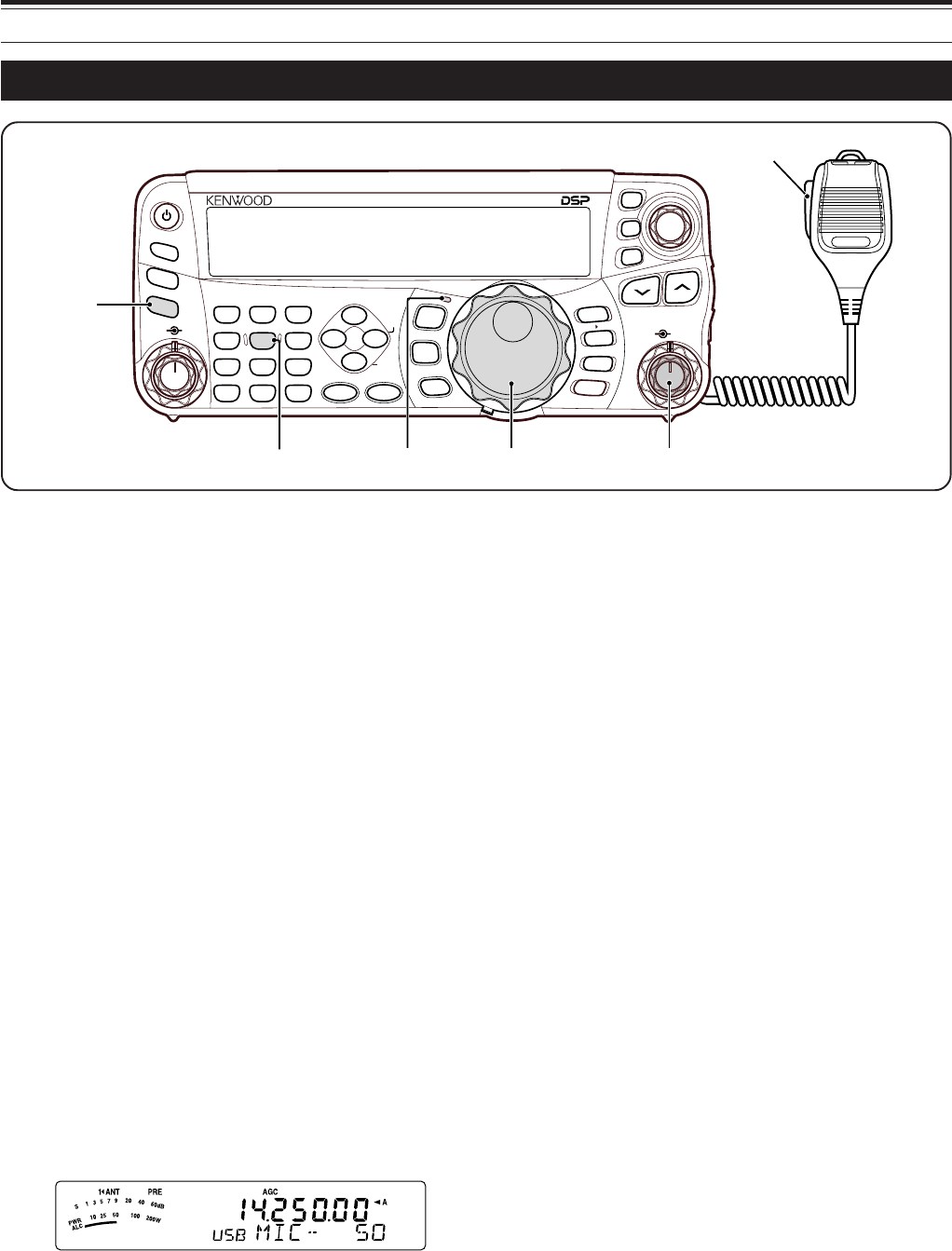
GETTING ACQUAINTED
REMOTE CONTROL PANEL
o
MIC/ 5/ RF.G key
Press to adjust the microphone gain {page 27}.
While the Speech Processor function is ON, press to
adjust the Speech Processor output level {page 37}.
Press and hold to adjust the receiver RF gain
{page 18}.
!0 KEY/ 6/ DELAY key
Press to adjust the internal electronic keyer speed.
Press and hold to adjust the VOX delay time {page
36} or break-in time (Full break-in/ Semi break-in
time) for CW mode {page 39}.
!1 NB/T/ 7 key
Press to switch the Noise Blanker ON or OFF. Press
and hold to adjust the Noise Blanker level {page 47}.
In FM mode, press to turn the Tone function ON or
OFF {page 32}. Press and hold to select a sub-audible
tone for the Tone funtion {page 32}.
!2 VOX/ 8 key
In Voice Mode, press to turn the VOX (Voice-
Operated Transmit) function ON or OFF {page 36}.
In CW mode, press to turn the Break-in function ON
or OFF {page 39}. Press and hold to adjust the
microphone input gain for VOX operation. The VOX
icon appears when the VOX (Voice)/ Break-in (CW)
function is active.
!3 PROC/ 9 key
Press to turn the Speech Processor ON or OFF
{page 37}. Press and hold to adjust the Speech
Processor input level. The PROC icon appears when
the Speech Processor function is ON.
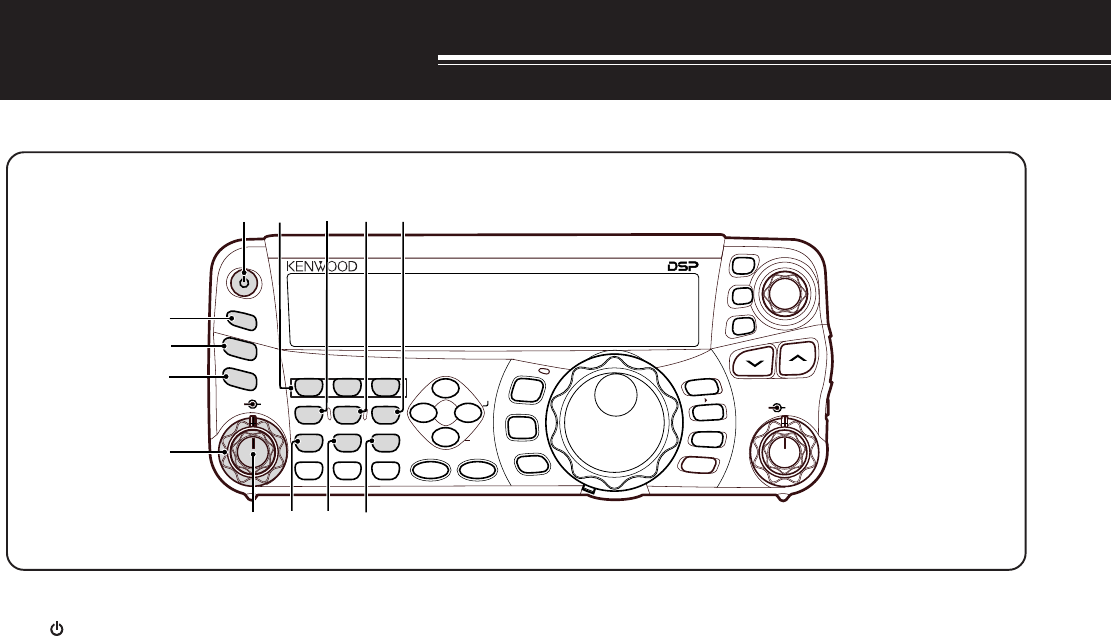
q [ ] (POWER) switch
Press and hold briefly to switch the transceiver power
ON. Press again to switch the power OFF {page 18}.
w PF key
You can assign a function to this Programmable
Function key. The default function is VOICE1
{page 64}.
e ATT/PRE/ ANT 1/2 key
Press to cycle between receiver attenuator ON, pre-
amplifier ON and OFF {pages 49, 61}.
Press and hold for 1 second, then release it to to
select either ANT 1 or ANT 2 {page 60}.
r AT
Press to activate the internal antenna tuner {page 60}
or an external antenna tuner. Press and hold to start
tuning the automatic antenna tuner.
t SQL control
Used for muting (“squelching”) the speaker, the head
phones and the AF output on DATA (8-pin mini DIN
connector) when no receive signal is present on the
transceiver {page 19}.
y AF control
Turn to adjust the audio volume on the transceiver
{page 18}.
u CH1/ 1/ REC, CH2/ 1/ REC, CH3/ 3/ REC key
Press to play back the CW or voice messages (the
VGS-1 is required) {page 40}. Press and hold to
record the voice messages (the VGS-1 is required)
{page 68} or CW messages that are associated with
the internal electronic keyer {page 40}.
i PWR/ 4/ TX MONI key
Press to adjust the transmission output power. Press
and hold to adjust the volume of the transmission
signal monitor function {page 65}.
NAR
1 REC 2 REC
5 RF.G
0 OFF
8
3 REC
9
4
7
TX MONI
6
DELAY
HF/50MHz ALL MODE TRANSCEIVER TS-480
CLR STEP SG.SEL
CW.T
F.LOCK
M/V
SPLIT
M VFO
M.IN
TF-SET
MULTI IF
SHIFT
AF SQL
PF
AT
CH1 CH2 CH3
PWR MIC KEY
VOX
PROC
AGC
ENT
A / B
A=B
MODE
MHz
QMI
QMR
MENU
MTR
NB/T
ANT 1/2
FINE SCAN
DNL
BC
NR FIL
RIT
XIT
CL
ATT/PRE
w
e
r
t
y
q !0u
!1 !3!2
io
11
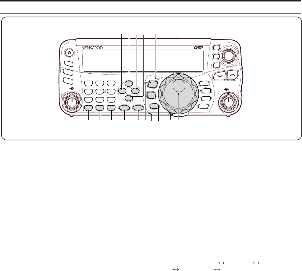
3 GETTING ACQUAINTED
!4 MTR/ CLR key
Press to select the meter scales {page 20} or exit
from, abort, or reset various functions. Press and
hold to clear memory channels {page 54}.
!5 AGC/ 0/ OFF key
Press to toggle the fast or slow response time for the
Automatic Gain Control (AGC). Press and hold to
switch the AGC OFF {page 35}.
!6 ENT key
Press to enter your desired frequency using the
keypad {page 34} or lock out memory channels from
the scan list {page 54}.
!7 FINE/ STEP key
Press to activate the Fine tuning function to allow
more precise tuning {page 35}. Press and hold to
select the frequency step size for the MULTI control
{page 34}.
!8 SCAN/ SG.SEL key
Press to start or stop the Scan function {page 56}.
Press and hold to select a Scan group {page 59}.
!9 NR key
Press to select the DSP Noise Reduction function,
NR1, NR2 or OFF {page 47}. When the Noise
Reduction function is turned ON, press and hold key
to change the parameter of the Noise Reduction
function {page 47}.
@0 DNL key
Press to turn the DNL (Digital Noise Limiter) function
ON or OFF. The “DNL” icon appears when it is ON.
Press and hold the key to change the level of DNL
function {page 47}.
@1 FIL/ NAR key
Press to configure the low-cut and high-cut filter
frequency for the DSP filter (AF). Press and hold to
select the narrow IF filter if available {page 45}.
@2 BC/ CW.T key
Press to select the DSP Beat Cancel funtion, BC1
(Beat Cancel 1), BC2 (Beat Cancel 2) or OFF
{page 47}. In CW mode, press to start the Auto CW
Tuning {page 29}.
@3 LED
Lights red when the transceiver is transmitting, lights
green when the transceiver is receiving signals, and
turns OFF when the transceiver mutes with the
squelch function.
@4 MODE key
Press to change the operating mode pair. There are
4 pairs: USB/ LSB, CW/ CWR, FSK/ FSR, and AM/ FM.
Press and hold for a second to toggle the mode
within each pair: USB LSB, CW CWR,
FSK FSR, or AM FM {page 19}.
@5 MENU/ F.LOCK key
Press to enter Menu Mode {page 22}. Press and hold
to activate the Frequency Lock function {page 63}.
@6 MHz key
Press to turn the MHz Up/ Down function ON or OFF.
The MHz digit increases or decreases when you turn
the MULTI control. Press and hold to change the
increment/ decrement step value {page 36}.
@7 Tuning control torque adjustment lever
The lever behind the Tuning control adjusts the
control torque level; turn clockwise for light torque or
counterclockwise for heavy torque.
@8 Tuning control
Turn to select the desired frequency {page 34}.
Use the convenient finger-tip cavity for continuous
tuning.
NAR
1 REC 2 REC
5 RF.G
0 OFF
8
3 REC
9
4
7
TX MONI
6
DELAY
HF/50MHz ALL MODE TRANSCEIVER TS-480
CLR STEP SG.SEL
CW.T
F.LOCK
M/V
SPLIT
M VFO
M.IN
TF-SET
MULTI IF
SHIFT
AF SQL
PF
AT
CH1 CH2 CH3
PWR MIC KEY
VOX
PROC
AGC
ENT
A / B
A=B
MODE
MHz
QMI
QMR
MENU
MTR
NB/T
ANT 1/2
FINE SCAN
DNL
BC
NR FIL
RIT
XIT
CL
ATT/PRE
!9 @0 @1
@4!4 !5 !6 !7 !8 @5@6
@2
@8
@3
@7
12
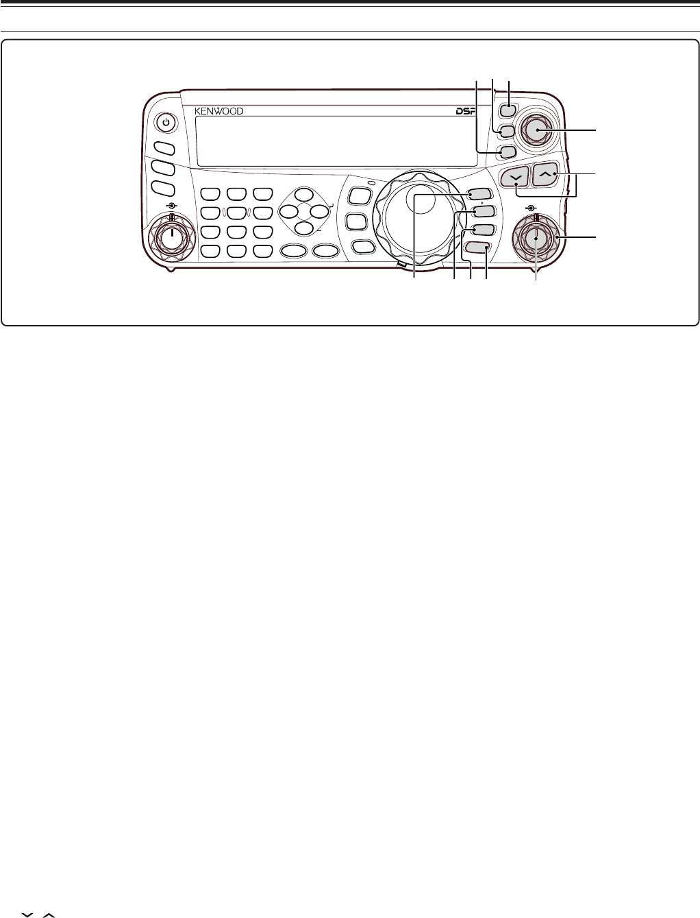
3 GETTING ACQUAINTED
@9 QMI/ M.IN key
Press to store data to the Quick Memory. Press and
hold to store the current operating frequencies and
other data to the Memory channel.
#0 QMR/ M
ss
ss
s
VFO key
Press to recall data from the Quick Memory
{page 55}. Press and hold to transfer the Memory
Channel frequencies and other data to the VFO.
#1 A/B / M/V key
Press to select either VFO A or VFO B {page 50}.
Press and hold to toggle between Memory and VFO
Modes.
#2 A=B/ SPLIT key
Press to duplicate the data in the currently selected
VFO to the other VFO {page 30}. Press and hold to
enter split-frequency operation which allows you to
use different transmission and reception frequencies
{page 30}.
#3 MULTI control
In VFO Mode, rotate to step the operating frequency
up or down {page 34}. In Memory Channel Mode,
rotate to select a Memory Channel {page 51}. Also,
used for selecting Menu numbers when accessing the
Menu Mode {page 52} and as a selector to choose
settings for various functions activated by Remote
Control panel keys.
#4 IF SHIFT control
Rotate to shift the center frequency of the IF passband
either lower or higher, to remove interference {page
45}.
#5 / key
Normally, press to step through all the Amateur radio
bands consecutively {page 19}. Also used to make
selections from the Menu {page 22} and to check the
Start and End frequencies of the Scan function
{page 53}. When both the split-frequency and the
frequency lock function are actived, press and hold to
perform the TF-SET function {page 30}.
#6 CL key
Press to clear the RIT/ XIT frequency to zero
{pages 35, 37}.
#7 XIT key
Press to turn the XIT (Transmit Incremental Tuning)
function ON or OFF {page 37}. When the XIT
function is ON, the XIT icon appears.
#8 RIT key
Press to turn the RIT (Receive Incremental Tuning)
function ON or OFF {page 35}. When the RIT
function is ON, the RIT icon appears.
#9 RIT/ XIT control
When the RIT/ XIT function is ON, turn to adjust the
offset frequency. The RIT/ XIT offset frequency
appears on the sub-display {pages 35, 37}.
NAR
1 REC 2 REC
5 RF.G
0 OFF
8
3 REC
9
4
7
TX MONI
6
DELAY
HF/50MHz ALL MODE TRANSCEIVER TS-480
CLR STEP SG.SEL
CW.T
F.LOCK
M/V
SPLIT
M VFO
M.IN
TF-SET
MULTI IF
SHIFT
AF SQL
PF
AT
CH1 CH2 CH3
PWR MIC KEY
VOX
PROC
AGC
ENT
A / B
A=B
MODE
MHz
QMI
QMR
MENU
MTR
NB/T
ANT 1/2
FINE SCAN
DNL
BC
NR FIL
RIT
XIT
CL
ATT/PRE
@9 #0 #3
#4
#5
#9
#6
#7
#2
#8
#1
13
3 GETTING ACQUAINTED
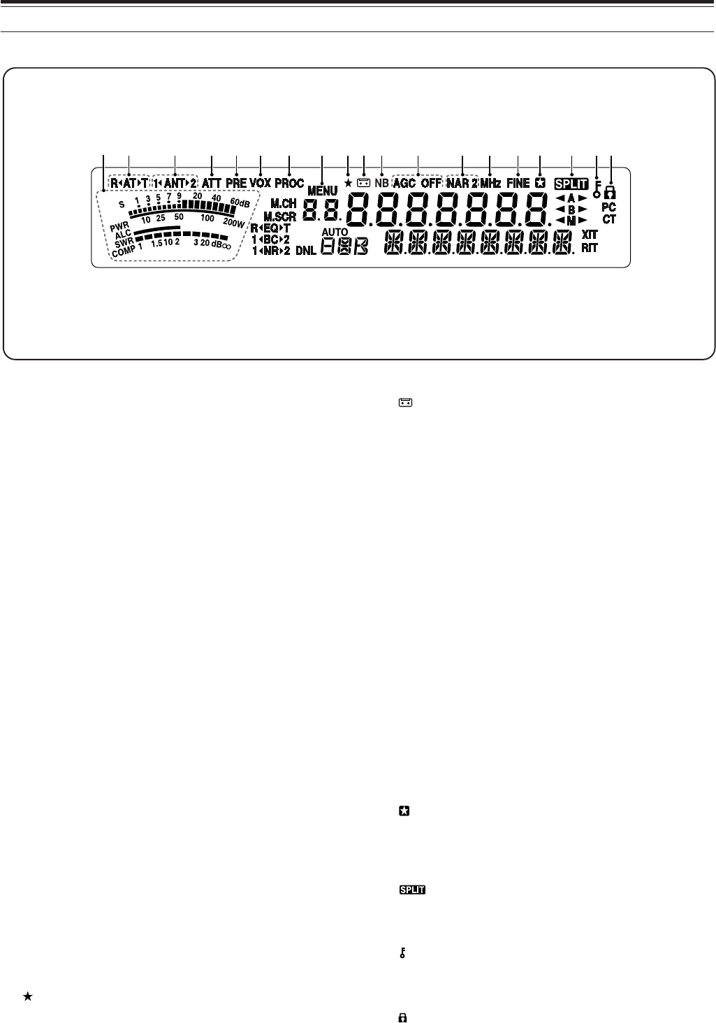
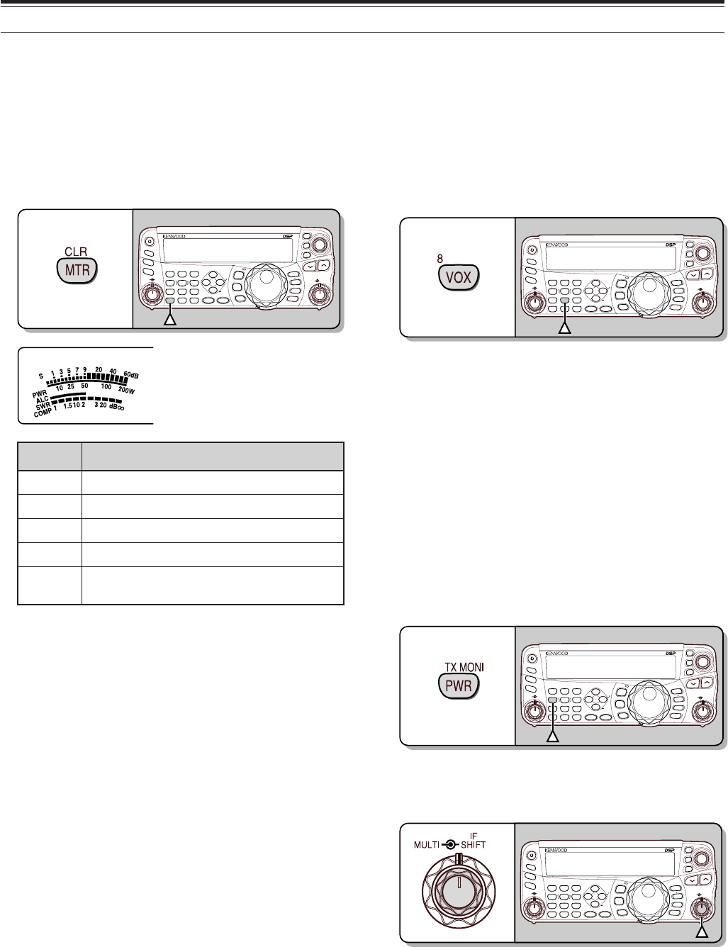
q METER
While receiving, serves as an S-meter to measure
and display the received signal strength. While
transmitting, serves as a power meter plus an ALC
meter, an SWR meter, or a Speech Processor
compression meter. The Peak Hold function holds
each reading for approximately half a second.
wR
t
AT
s
T
Appears while the internal antenna tuner {page 60} or
an external antenna tuner is in-line for the operation.
e 1
t
ANT
s
2
Either “1
t
ANT” or “ANT
s
2” appears, depending on
which antenna connector is selected for the operation
{page 60}.
rATT
Appears when the receiver’s attenuator (approx.
12 dB) is ON {pages 49, 61}.
tPRE
Appears when the receiver pre-amplifier (approx.
6 dB) is ON {page 49}.
y VOX
Appears when the VOX (Voice Operated
Transmission) function is ON or the Break-in function
is ON for the CW mode {pages 36, 39}.
u PROC
Appears when the Speech Processor function is ON
{page 37}.
i MENU
Appears when configuring the parameters in the
Menu Mode {page 22}.
o
Reserved for the future updates.
q w e r t y u o!0 !1 !4 !5 !6 !7 !8!9i !2 !3
!0
Appears while the Constant Recording function is ON
{page 70}.
!1 NB
Appears when the Noise Blanker is ON {page 47}.
!2 AGC OFF
“AGC - F” (fast) or “AGC” (slow) appears when the
AGC (Automatic Gain Control) function is ON. “AGC
OFF” appears when the AGC is OFF {page 35}.
!3 NAR 2
“NAR” appears when the narrow IF filter is selected
for the operating mode. If two optional IF filters are
installed and the transceiver selects the secondary IF
filter, “NAR 2” appears {page 45}.
!4 MHz
Appears when the MHz Up/ Down mode using the
MULTI control is ON {page 34}. It also appears when
the Quick Menu function is ON {page 22}.
!5 FINE
Appears when the Fine function is ON {page 35}.
!6
Appears when the selected Menu No. is in the Quick
Menu list. It also appears when you specify the slow
down frequency points {page57}.
!7
Appears when the split-frequency operation is ON
{page 30}.
!8
Appears when the Tuning control Lock function is ON
{page 63}.
!9
Appears when the Frequency Lock function is ON
{page 63}.
LCD DISPLAY
14
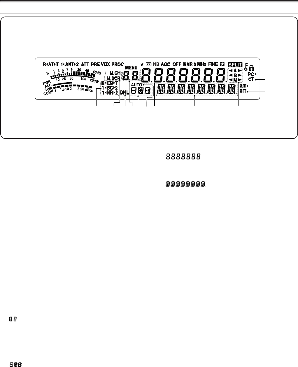
3 GETTING ACQUAINTED
@0 R
tt
tt
t
EQ
ss
ss
s
T
“R
tt
tt
t
EQ” appears when the RX Equalizer function is
ON {page 64}. “EQ
ss
ss
s
T” appears when the TX
Equalizer function is ON {page 38}.
@1 1
t
BC
s
2
“1
t
BC” or “BC
ss
ss
s
2” appears, as you select the DSP
Beat Cancel 1 or Beat Cancel 2 {page 47}.
@2 1
tt
tt
t
NR
ss
ss
s
2
“1
tt
tt
t
NR” or “NR
ss
ss
s
2” appears, depending on whether
DSP Noise Reduction 1 (Line Enhanced method) or
Noise Reduction 2 (SPAC method) is selected
{page 47}.
@3 M.CH
Appears in Memory Recall Mode {page 51}.
@4 M.SCR
Appears in Memory Scroll Mode {page 52}.
@5 DNL
Appears when the Digital Noise Limiter function is ON
{page 47}.
@6
Shows the Memory Channel number for the
transceiver. In Menu Mode, it displays the Menu No.
In Quick Memory Mode, it shows the Quick Memory
number location (the Quick Memory number ranges
from “0_” to “9_”) {page 55}.
@7
Displays a communication mode {page 19}.
@8 AUTO
Appears when Auto Mode function is ON {page 61}.
@9
The transceiver operating frequency display. In Menu
Mode, it displays the parameters.
#0
In the normal operating mode, it displays the
transceiver status and Menu item descriptions when
necessary. While the RIT, XIT or SPLIT function is
turned ON, it is used to display the frequency
information for these functions {pages 35, 37}.
#1
t
A
s
“
t
A” or “A
s
” appears while VFO A is selected
{page 30}. “A” appears while Menu A is being
accessed in the Menu Mode {page 22}.
#2
t
B
s
“
t
B” or “B
s
” appears while VFO B is selected
{page 30}. “B” appears while Menu B is being
accessed in the Menu Mode {page 22}.
#3
t
M
s
“
t
M” or “M
s
” appears while a simplex memory
channel is selected {page 50}.
#4 RIT
Appears when Receive Incremental Tuning function is
ON {page 35}.
#5 XIT
Appears when Transmit Incremental Tuning function
is ON {page 37}.
#6 CT
“T” appears when the Tone function is ON {page 32}.
“CT” appears when the CTCSS (Continuous Tone
Coded Squelch System) is ON {page 33}.
#7 PC
Appears when the transceiver is being controlled by a
PC {page 67}.
#1#2#3
#0@9@8@7@5
@3@4
@0@1@2
#4
#5
#6
#7
@6
15
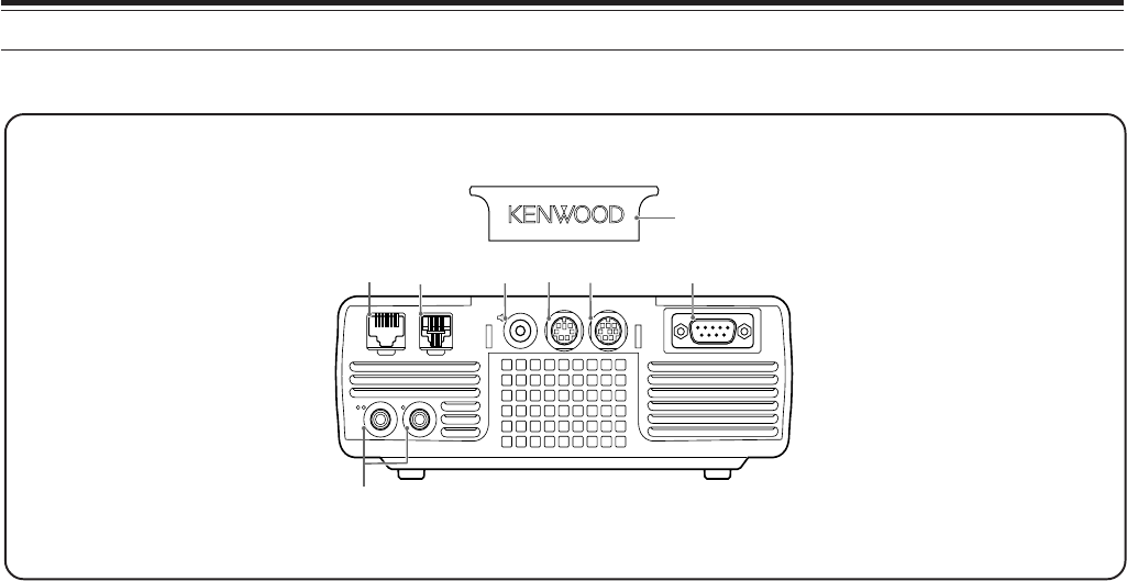
3 GETTING ACQUAINTED
qMIC connector
Connect a cable from the supplied microphone to this
connector {page 6}.
wPANEL connector
Connect a cable from the Remote Control panel to
this connector {page 6}.
eEXT.SP jack
Mate with a 3.5 mm (1/8"), 2-conductor (mono) plug
for connecting an external speaker {page 7}.
rDATA connector
Mates with a 6-pin male DIN connector for connecting
various accessory equipment, such as an external
TNC/ MCP or a RTTY terminal {pages 80, 81}.
tREMOTE connector
Mates with a 6-pin male mini DIN connector for
connecting an HF/ 50 MHz linear amplifier {page 80}.
yCOM connector
Mates with a DB-9 female connector for connecting a
computer via one of its serial communication (COM)
ports {page 79}. Also used with the Quick Data
Transfer function {page 79} and DX Packet Cluster
Tune function {page 82}.
uPADDLE and KEY jacks
The PADDLE jack mates with a 6.3 mm (1/4")
3-conductor plug for connecting a keyer paddle to the
internal electronic keyer. The KEY jack mates with a
3.5 mm (1/8") 2-conductor plug for connecting an
external key for CW operation. Refer to “Keys for
CW (PANEL and KEY)” {page 7} before using these
jacks.
iPlastic cover
If the EXT.SP jack, DATA connector and REMOTE
connector are not used, attach this cover to protect
the connectors from dust.
TX/ RX UNIT
MIC PANEL
PADDLE KEY
EXT.SP DATA REMOTE
COM
qw ert y
u
i
16
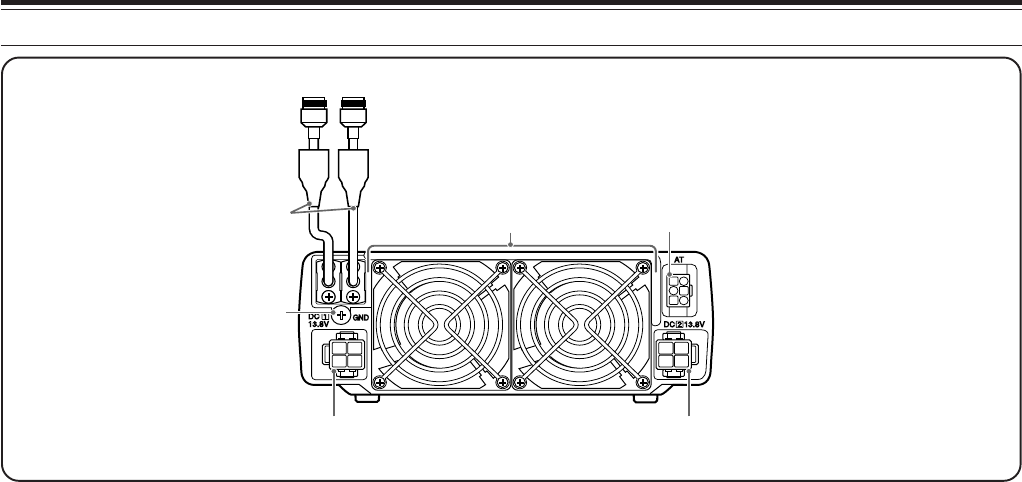
3 GETTING ACQUAINTED
qANT 1 and ANT 2 connectors
Connect your primary HF/ 50 MHz antenna to ANT 1.
If you are using 2 antennas for the HF/ 50 MHz band,
connect the secondary antenna to the ANT 2 connector.
wGND post
Connect a heavy gauge wire or copper strap between
the ground post and the nearest earth ground or vehicle
body {pages 2, 4}.
eCooling Fans
The TS-480SAT is equipped with 1 cooling fan.
The TS-480HX is equipped with 2 cooling fans.
Air flows in from these fans.
rAT connector
Mates with the connecter from the cable supplied with
the AT-300 external antenna tuner. Refer to the
instruction manual supplied with the tuner for more
information.
tDC 1 13.8 V DC power input connector
Connect a primary 13.8 V DC power source to this
connector {pages 2, 3}. Use the DC cable supplied
with the transceiver.
yDC 2 13.8 V DC power input connector
(TS-480HX only)
You must connect a secondary 13.8 V DC power
source to this connector in order to transmit
{pages 2, 3}. Use the cable supplied with the
transceiver. If no DC power source is available on
this connector, you cannot transmit at any output
er
w
y
t
q
ANT 1ANT 2
17
3 GETTING ACQUAINTED
REMOTE CONTROL PANEL (REAR)
qSpeaker
When the headphones are connected, the
q
power. However, you can still receive {page 18}.
speaker mutes.
MICROPHONE
PTT
DWN UP
q
w
qUP/ DWN keys
Use these keys to step the VFO frequency, Memory
Channels, or Menu selections up and down.
Press and hold these keys to continuously change
the settings.
wPTT (Push-to-Talk) switch
The transceiver is placed in Transmission Mode when
this non-locking switch is held down. Releasing the
switch returns the transceiver to Reception Mode.
18
OPERATING BASICS
SWITCHING POWER ON/ OFF
1Switch the DC power supply(s) ON if you are
using a DC power supply(s).
2Press and hold [ ] (POWER) briefly to switch
the transceiver ON.
NAR
1 REC 2 REC
5 RF.G
0 OFF
8
3 REC
9
4
7
TX MONI
6
DELAY
HF/50MHz ALL MODE TRANSCEIVER TS-480
CLR STEP SG.SEL
CW.T
F.LOCK
M/V
SPLIT
M VFO
M.IN
TF-SET
MULTI IF
SHIFT
AF SQL
PF
AT
CH1 CH2 CH3
PWR MIC KEY
VOX
PROC
AGC
ENT
A / B
A=B
MODE
MHz
QMI
QMR
MENU
MTR
NB/T
ANT 1/2
FINE SCAN
DNL
BC
NR FIL
RIT
XIT
CL
ATT/PRE
• Do not press the switch for more than
approximately 2 seconds; the transceiver will
be switched OFF.
•TS-480HX only: If “RX ONLY” appears on the
sub-display upon power up, confirm that two
DC cable connectors are securely connected to
the DC-1 and DC-2 connectors. When this
warning message appears, you can receive
signals as usual but you cannot transmit even if
you decrease the output power. “TWIN PWR”
appears when two DC power cables are
connected to the DC-1 and DC-2 connectors.
• Upon power up, “HELLO” appears on the main
display, followed by the selected frequency and
other indicators.
3To switch the transceiver OFF, press [ ]
(POWER) again.
4Switch the DC power supply(s) OFF.
• You may skip step 3. After switching the
transceiver ON, you can switch it OFF or ON
using only the power switch of the DC power
supply(s). The transceiver remembers the
information of the POWER switch position
when the DC power source is switched OFF.
ADJUSTING VOLUME
AF (AUDIO FREQUENCY) GAIN
Turn the AF control clockwise to increase the audio
level and counterclockwise to decrease the level.
NAR
1 REC 2 REC
5 RF.G
0 OFF
8
3 REC
9
4
7
TX MONI
6
DELAY
HF/50MHz ALL MODE TRANSCEIVER TS-480
CLR STEP SG.SEL
CW.T
F.LOCK
M/V
SPLIT
M VFO
M.IN
TF-SET
MULTI IF
SHIFT
AF SQL
PF
AT
CH1 CH2 CH3
PWR MIC KEY
VOX
PROC
AGC
ENT
A / B
A=B
MODE
MHz
QMI
QMR
MENU
MTR
NB/T
ANT 1/2
FINE SCAN
DNL
BC
NR FIL
RIT
XIT
CL
ATT/PRE
AF SQL
Note:
The position of the
AF
control does not affect the volume of
beeps caused by pressing keys nor the CW TX sidetone. The audio
level for Digital mode operation is also independent of the
AF
control
setting.
RF (RADIO FREQUENCY) GAIN
The RF GAIN is normally configured to the maximum
level regardless of the operating modes. The
transceiver has been configured to the maximum
level at the factory. However, you may decrease the
RF GAIN slightly when you have trouble hearing the
desired signal because of excessive atmospheric
noise or interference from other stations. First, take
note of the peak S-meter reading of the desired
signal.
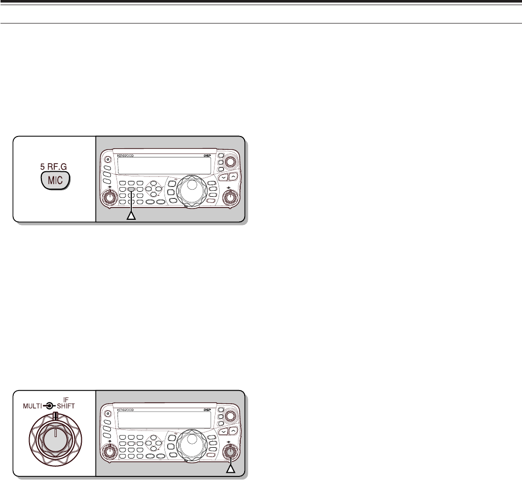
1Press [MIC/ RF.G] (1 s).
NAR
1 REC 2 REC
5 RF.G
0 OFF
8
3 REC
9
4
7
TX MONI
6
DELAY
HF/50MHz ALL MODE TRANSCEIVER TS-480
CLR STEP SG.SEL
CW.T
F.LOCK
M/V
SPLIT
M VFO
M.IN
TF-SET
MULTI IF
SHIFT
AF SQL
PF
AT
CH1 CH2 CH3
PWR MIC KEY
VOX
PROC
AGC
ENT
A / B
A=B
MODE
MHz
QMI
QMR
MENU
MTR
NB/T
ANT 1/2
FINE SCAN
DNL
BC
NR FIL
RIT
XIT
CL
ATT/PRE
• The current RF GAIN level appears on the
sub-display (0: minimum ~ 100: maximum).
2Turn the MULTI control counterclockwise until the
S-meter reads the peak value that you noted.
NAR
1 REC 2 REC
5 RF.G
0 OFF
8
3 REC
9
4
7
TX MONI
6
DELAY
HF/50MHz ALL MODE TRANSCEIVER TS-480
CLR STEP SG.SEL
CW.T
F.LOCK
M/V
SPLIT
M VFO
M.IN
TF-SET
MULTI IF
SHIFT
AF SQL
PF
AT
CH1 CH2 CH3
PWR MIC KEY
VOX
PROC
AGC
ENT
A / B
A=B
MODE
MHz
QMI
QMR
MENU
MTR
NB/T
ANT 1/2
FINE SCAN
DNL
BC
NR FIL
RIT
XIT
CL
ATT/PRE
• Signals that are weaker than this level will be
attenuated and reception of the station will
become easier.
Depending on the type and gain of your antenna, and
the condition of the band, adjust the RF GAIN. When
using FM Mode, always adjust the RF GAIN to the
maximum level.
SELECTING VFO A OR VFO B
2 VFOs are available for controlling the frequency on
the transceiver. Each VFO (VFO A and VFO B)
works independently so that a different frequency and
mode can be selected. For example, when SPLIT
operation is activated, VFO A is used for reception
and VFO B is used for transmission. The opposite
combination is also possible.
Press [A/B / M/V] to toggle between VFO A and B.
NAR
1 REC 2 REC
5 RF.G
0 OFF
8
3 REC
9
4
7
TX MONI
6
DELAY
HF/50MHz ALL MODE TRANSCEIVER TS-480
CLR STEP SG.SEL
CW.T
F.LOCK
M/V
SPLIT
M VFO
M.IN
TF-SET
MULTI IF
SHIFT
AF SQL
PF
AT
CH1 CH2 CH3
PWR MIC KEY
VOX
PROC
AGC
ENT
A / B
A=B
MODE
MHz
QMI
QMR
MENU
MTR
NB/T
ANT 1/2
FINE SCAN
DNL
BC
NR FIL
RIT
XIT
CL
ATT/PRE
•“
t
A” or “
t
B” appears to indicate which VFO is
selected.
19
4 OPERATING BASICS
SELECTING A BAND
Press [ ]/ [ ] to select your desired band.
• Holding down either key changes the bands
continuously.
NAR
1 REC 2 REC
5 RF.G
0 OFF
8
3 REC
9
4
7
TX MONI
6
DELAY
HF/50MHz ALL MODE TRANSCEIVER TS-480
CLR STEP SG.SEL
CW.T
F.LOCK
M/V
SPLIT
M VFO
M.IN
TF-SET
MULTI IF
SHIFT
AF SQL
PF
AT
CH1 CH2 CH3
PWR MIC KEY
VOX
PROC
AGC
ENT
A / B
A=B
MODE
MHz
QMI
QMR
MENU
MTR
NB/T
ANT 1/2
FINE SCAN
DNL
BC
NR FIL
RIT
XIT
CL
ATT/PRE
SELECTING A MODE
Press [MODE] to cycle through the 4 mode pairs:
USB/ LSB, CW/ CWR, FSK/ FSR, and AM/ FM. Each
time you press [MODE], the mode display cycles
USB or LSB, CW or CWR, FSK or FSR, FM or AM.
To select the other mode on each pair, press [MODE]
(1 s). For example, to select “LSB” while “USB” is
visible, press [MODE] (1 s). “USB” changes to
“LSB”. Press [MODE] (1 s) again to go back to
“LSB” from “USB”. The following illustration
describes how to access each mode with the [MODE]
key.
NAR
1 REC 2 REC
5 RF.G
0 OFF
8
3 REC
9
4
7
TX MONI
6
DELAY
HF/50MHz ALL MODE TRANSCEIVER TS-480
CLR STEP SG.SEL
CW.T
F.LOCK
M/V
SPLIT
M VFO
M.IN
TF-SET
MULTI IF
SHIFT
AF SQL
PF
AT
CH1 CH2 CH3
PWR MIC KEY
VOX
PROC
AGC
ENT
A / B
A=B
MODE
MHz
QMI
QMR
MENU
MTR
NB/T
ANT 1/2
FINE SCAN
DNL
BC
NR FIL
RIT
XIT
CL
ATT/PRE
MODE
MODE
MODE
MODE
MODE
(1 s)
MODE
(1 s)
MODE
(1 s)
MODE
(1 s)
Access Menu No. 2 then press [ ] to select “on” to
turn the Auto Mode selection ON. When it is ON,
“AUTO” appears. As a default setting, if you change
the frequency above or below 9.5 MHz, the
transceiver automatically switches modes; LSB for
frequencies under 9.5 MHz and USB for frequencies
equal to or over 9.5 MHz. You can further add the
frequency table data to change the mode
automatically {page 61}.
ADJUSTING SQUELCH
The purpose of the Squelch is to mute the speaker
when no signals are present. With the squelch level
correctly set, you will hear sound only while actually
receiving signals. The higher the selected squelch
level, the stronger the signals must be to receive.
The appropriate squelch level depends on the
ambient RF noise conditions.
Turn the SQL control when there are no signals
present to select the squelch level at which the
background noise is just eliminated; the green LED
will turn off. Many ham operators prefer leaving the
SQL control fully counterclockwise unless operating
on a full-carrier mode such as FM. The squelch
level for the main transceiver is preset at the factory
to approximately the 9 o’clock position for FM and 11
o’clock for SSB and AM.
NAR
1 REC 2 REC
5 RF.G
0 OFF
8
3 REC
9
4
7
TX MONI
6
DELAY
HF/50MHz ALL MODE TRANSCEIVER TS-480
CLR STEP SG.SEL
CW.T
F.LOCK
M/V
SPLIT
M VFO
M.IN
TF-SET
MULTI IF
SHIFT
AF SQL
PF
AT
CH1 CH2 CH3
PWR MIC KEY
VOX
PROC
AGC
ENT
A / B
A=B
MODE
MHz
QMI
QMR
MENU
MTR
NB/T
ANT 1/2
FINE SCAN
DNL
BC
NR FIL
RIT
XIT
CL
ATT/PRE
SELECTING A FREQUENCY
Turn the Tuning control clockwise or press Mic [UP]
to increase the frequency. Turn the Tuning control
counterclockwise or press Mic [DWN] to decrease the
frequency.
NAR
1 REC 2 REC
5 RF.G
0 OFF
8
3 REC
9
4
7
TX MONI
6
DELAY
HF/50MHz ALL MODE TRANSCEIVER TS-480
CLR STEP SG.SEL
CW.T
F.LOCK
M/V
SPLIT
M VFO
M.IN
TF-SET
MULTI IF
SHIFT
AF SQL
PF
AT
CH1 CH2 CH3
PWR MIC KEY
VOX
PROC
AGC
ENT
A / B
A=B
MODE
MHz
QMI
QMR
MENU
MTR
NB/T
ANT 1/2
FINE SCAN
DNL
BC
NR FIL
RIT
XIT
CL
ATT/PRE
You may prefer directly entering a frequency using
the numeric keypad if the desired frequency is far
from the current frequency. Press [ENT], then press
the numeric keys as necessary. For details, refer to
“Direct Frequency Entry” {page 34}.
1
CH1/REC
2
CH2/REC
3
CH3/REC
4
TONE/SEL
5
METER
6
CTCSS/SEL
7
NB/LEVEL
8
AGC/OFF
9
FINE/STEP
.
DCS/SEL
0
SHIFT/OFFSET
ENT
PF
F LOCK A
1
CH1/REC
2
CH2/REC
3
CH3/REC
4
TONE/SEL
5
METER
6
CTCSS/SEL
7
NB/LEVEL
8
AGC/OFF
9
FINE/STEP
.
DCS/SEL
0
SHIFT/OFFSET
ENT
SEND
PHONES
MIC
AT
ANT1/2
PROC
LEVEL
VOX
ATT PRE
LEVEL
LEVEL
LEVEL
MANUAL
LO/
WIDTH
HI/
SHIFT
N.R.
A.N.
B.C.
FUNC
CLR
MAIN
AUTO
CAR
TX MONI
DELAY NAR
REV
MIC
PWR
KEY
LSB
USB
CW
FSK
FM
AM
DISP
SEL
1MHz CTRL
ME
N
M
HF/VHE/UHF ALL M
O
This transceiver provides many other methods for
quickly selecting a frequency. For further information,
refer to “SELECTING YOUR FREQUENCY”
{page 34}.
4 OPERATING BASICS
20
FRONT PANEL METER
The multi-function meter measures the parameters in
the table below. The S-meter scale appears when
the transceiver is in reception mode, and the PWR
meter appears when it is in transmission mode.
Each time you press [MTR/ CLR], it cycles between
the ALC, SWR, and COMP meters. Peak readings
for the S-meter, ALC, SWR, COMP, and PWR
functions are held momentarily.
NAR
1 REC 2 REC
5 RF.G
0 OFF
8
3 REC
9
4
7
TX MONI
6
DELAY
HF/50MHz ALL MODE TRANSCEIVER TS-480
CLR STEP SG.SEL
CW.T
F.LOCK
M/V
SPLIT
M VFO
M.IN
TF-SET
MULTI IF
SHIFT
AF SQL
PF
AT
CH1 CH2 CH3
PWR MIC KEY
VOX
PROC
AGC
ENT
A / B
A=B
MODE
MHz
QMI
QMR
MENU
MTR
NB/T
ANT 1/2
FINE SCAN
DNL
BC
NR FIL
RIT
XIT
CL
ATT/PRE
Multi-function meter
reteM ?derusaeMsItahW
SslangisdeviecerfohtgnertS
RWP rewoptuptuonoissimsnarT
CLA sutatslortnoclevelcitamotuA
RWS oitarevawgnidnatsmetsysannetnA
PMOC gnisunehwlevelnoisserpmochceepS }73egap{rossecorPhceepSeht
Note:
◆
The COMP meter functions only when the Speech Processor is
ON for SSB, FM, or AM mode.
◆
Peak Hold readings cannot be deactivated.
TRANSMITTING
For voice communications, press and hold Mic [PTT],
then speak into the microphone in your normal tone
of voice. When you finish speaking, release Mic
[PTT] to receive.
To transmit CW, press [VOX/ 8] to switch the Break-in
function ON. “VOX” appears. Close the key or keyer
paddle. Connect a key or keyer paddle {pages 7, 15},
then select CW using [MODE] {page 19}.
NAR
1 REC 2 REC
5 RF.G
0 OFF
8
3 REC
9
4
7
TX MONI
6
DELAY
HF/50MHz ALL MODE TRANSCEIVER TS-480
CLR STEP SG.SEL
CW.T
F.LOCK
M/V
SPLIT
M VFO
M.IN
TF-SET
MULTI IF
SHIFT
AF SQL
PF
AT
CH1 CH2 CH3
PWR MIC KEY
VOX
PROC
AGC
ENT
A / B
A=B
MODE
MHz
QMI
QMR
MENU
MTR
NB/T
ANT 1/2
FINE SCAN
DNL
BC
NR FIL
RIT
XIT
CL
ATT/PRE
For a detailed explanation on transmitting, refer to
“BASIC COMMUNICATIONS”, beginning on page 27.
SELECTING TRANSMISSION POWER
It is wise to select a lower transmission power if
communication is still reliable. This lowers the risk of
interfering with others on the band. When operating
from battery power, selecting a lower transmission
power allows you more operating time before
recharging is necessary. This transceiver allows you
to change the transmission power even while
transmitting.
1Press [PWR/ 4/ TX MONI].
• The current transmission power appears.
NAR
1 REC 2 REC
5 RF.G
0 OFF
8
3 REC
9
4
7
TX MONI
6
DELAY
HF/50MHz ALL MODE TRANSCEIVER TS-480
CLR STEP SG.SEL
CW.T
F.LOCK
M/V
SPLIT
M VFO
M.IN
TF-SET
MULTI IF
SHIFT
AF SQL
PF
AT
CH1 CH2 CH3
PWR MIC KEY
VOX
PROC
AGC
ENT
A / B
A=B
MODE
MHz
QMI
QMR
MENU
MTR
NB/T
ANT 1/2
FINE SCAN
DNL
BC
NR FIL
RIT
XIT
CL
ATT/PRE
4
2Turn the MULTI control counterclockwise to
reduce the power or clockwise to increase the
power.
NAR
1 REC 2 REC
5 RF.G
0 OFF
8
3 REC
9
4
7
TX MONI
6
DELAY
HF/50MHz ALL MODE TRANSCEIVER TS-480
CLR STEP SG.SEL
CW.T
F.LOCK
M/V
SPLIT
M VFO
M.IN
TF-SET
MULTI IF
SHIFT
AF SQL
PF
AT
CH1 CH2 CH3
PWR MIC KEY
VOX
PROC
AGC
ENT
A / B
A=B
MODE
MHz
QMI
QMR
MENU
MTR
NB/T
ANT 1/2
FINE SCAN
DNL
BC
NR FIL
RIT
XIT
CL
ATT/PRE
• The selectable range differs, depending on the
transceiver model, the current band, and the
mode.
3Press [PWR/ 4/ TX MONI] to complete the setting.
Note:
You may access Menu No. 21, and select “on” to change the
step size from 5 W to 1 W {page 65}.
4 OPERATING BASICS
21
MICROPHONE GAIN
The microphone gain must be adjusted when SSB
or AM mode is selected without using the speech
processor {pages 27, 28}.
1Press [MIC/ 5/ RF.G].
• The current microphone gain level appears.
The range is from 0 to 100 with a default of 50.
NAR
1 REC 2 REC
5 RF.G
0 OFF
8
3 REC
9
4
7
TX MONI
6
DELAY
HF/50MHz ALL MODE TRANSCEIVER TS-480
CLR STEP SG.SEL
CW.T
F.LOCK
M/V
SPLIT
M VFO
M.IN
TF-SET
MULTI IF
SHIFT
AF SQL
PF
AT
CH1 CH2 CH3
PWR MIC KEY
VOX
PROC
AGC
ENT
A / B
A=B
MODE
MHz
QMI
QMR
MENU
MTR
NB/T
ANT 1/2
FINE SCAN
DNL
BC
NR FIL
RIT
XIT
CL
ATT/PRE
2Press and hold Mic [PTT].
• The LED on the panel lights red.
3SSB: While speaking into the microphone, adjust
the MULTI control so that the ALC meter reflects
your voice level but does not exceed the ALC limit.
AM: While speaking into the microphone, adjust
the MULTI control so that the power meter slightly
reflects your voice level.
FM: Access Menu No. 44 and select “1” (Low), “2”
(Medium), or “3” (High) for the microphone gain,
if necessary {page 27}.
NAR
1 REC 2 REC
5 RF.G
0 OFF
8
3 REC
9
4
7
TX MONI
6
DELAY
HF/50MHz ALL MODE TRANSCEIVER TS-480
CLR STEP SG.SEL
CW.T
F.LOCK
M/V
SPLIT
M VFO
M.IN
TF-SET
MULTI IF
SHIFT
AF SQL
PF
AT
CH1 CH2 CH3
PWR MIC KEY
VOX
PROC
AGC
ENT
A / B
A=B
MODE
MHz
QMI
QMR
MENU
MTR
NB/T
ANT 1/2
FINE SCAN
DNL
BC
NR FIL
RIT
XIT
CL
ATT/PRE
4Release Mic [PTT] to return to receive.
• The LED lights green or turns off, depending
on the SQL control setting.
Note:
When using the optional MC-90 microphone with the MJ-88 in
FM mode, select “3” (High) for the microphone gain. The microphone
sensitivity is low in FM mode. This may cause insufficient
modulation. For other microphones, select either “1” (Low) or “2”
(Medium).
22
MENU SETUP
WHAT IS A MENU?
Many functions on this transceiver are selected or
configured via a software-controlled Menu, rather
than through the physical controls of the transceiver.
Once familiar with the Menu system, you will
appreciate the versatility it offers. You can customize
the various timings, settings, and programming
functions on this transceiver to meet your needs
without using many controls and switches.
MENU A/ MENU B
This transceiver has 2 menus: Menu A and Menu B.
These menus contain identical functions and can be
configured independently. The transceiver, therefore,
allows you to switch between 2 different
environments quickly and easily. For example, you
can configure Menu A for DXing and contesting while
Menu B is for relaxed local ragchewing. By switching
from Menu A to Menu B, you can instantly change the
Menu configuration and key assignment to suit your
current operating style. Or, 2 operators may share a
single transceiver by dedicating one Menu to each
operator. Both operators can always enjoy their own
configuration.
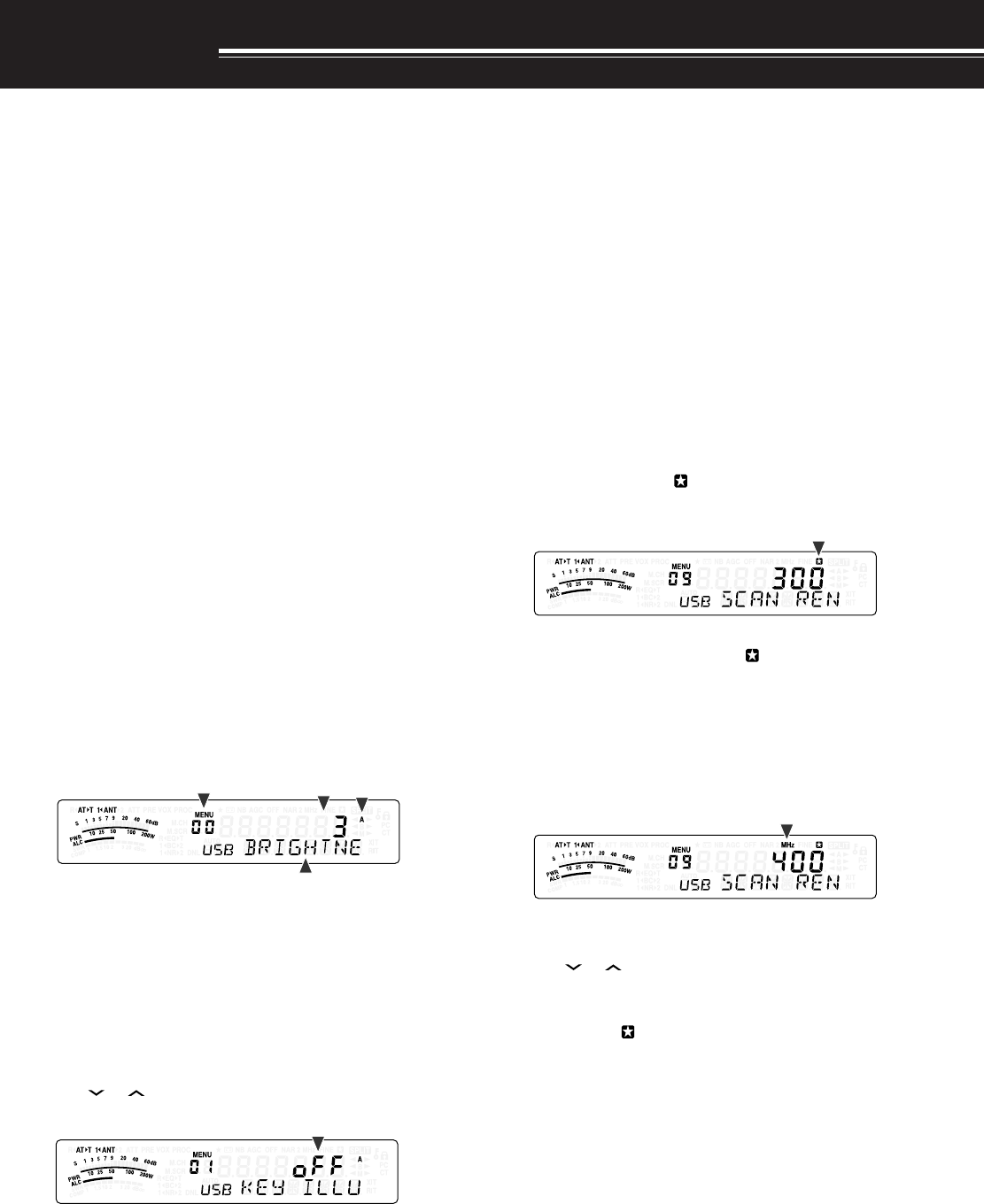
MENU ACCESS
1Press [MENU/ F.LOCK].
• The Menu No. and setting appear on the
display, and the explanation of the menu
appears on the sub-display.
2Press [A/B / M/V] to select Menu A or Menu B.
• “A” or “B” appears, indicating which Menu is
selected.
3Turn the MULTI control to select the desired Menu
No.
• Each time you change the Menu No.,
a different scrolling message appears on the
sub-display, describing the Menu No.
4Press []/ [ ], or Mic [UP]/ [DWN] to select a
parameter.
5Press [MENU/ F.LOCK] to exit Menu mode.
QUICK MENU
Because the number of functions this transceiver
provides is extraordinary, there are numerous items in
each Menu. If you find accessing desired Menu Nos.
to be too time consuming, use the Quick Menu to
create your own customized, abbreviated Menu. You
can then add those Menu Nos. which you frequently
use, to the Quick Menu. Copying Menu Nos. to the
Quick Menu has no effect on the Menu.
PROGRAMMING THE QUICK MENU
1Press [MENU/ F.LOCK].
2Turn the MULTI control to select the desired Menu
No.
3Press [QMI/ M.IN].
• An inverted star, “ ” appears, indicating that
the Menu item has been added to the Quick
Menu.
• To remove the item from the Quick Menu,
press [QMI/ M.IN] again. “ ” disappears.
4Press [MENU/ F.LOCK] to exit Menu mode.
USING THE QUICK MENU
1Press [MENU/ F.LOCK].
2Press [MHz].
• “MHz” appears.
3Turn the MULTI control to select the desired Quick
Menu No.
4Press [ ]/ [ ], or Mic [UP]/[DWN] to change the
current setting for the selected Menu No.
• When the Menu is registered to the Quick
Menu list, “ ” appears.
5Press [MENU/ F.LOCK] to exit Quick Menu mode.
Note:
If the Quick Menu has not been programmed, turning the
MULTI
control in step 2 causes “CHECK” to be output in Morse code.

23
5 MENU SETUP
puorG
uneM .oN
noitcnuF snoitceleS tluafeD .feR gaPe
rotarepO ecafretnI
00 ssenthgirbyalpsiD mumixam:4,muminim:1,FFO 4ot1/FFo336
10noitanimulliyeKno/FFono36
20noitarepoedomotuAno/FFoFFo16
gninuT lortnoC
30noituloverrepegnahclortnocgninuT0001/005/05200553
40htiwgninuT ITLUM edomMFnilortnocno/FFoFFo43
50 gnisuybdegnahcseicneuqerfOFVffosdnuoReht ITLUM lortnoc no/FFono43
60 ehtrofezispetsycneuqerfzHk9 ITLUM lortnoc
dnabtsacdaorbMAehtnoedomMAni no/FFo
eeS ecnerefeR egaP
43
yromeM lennahC 70 lennahcyromem)FFO(dexifro)NO(elbanuT seicneuqerf no/FFoFFo25
nacS noitarepO
80dewolsyllaitrapnacsmargorPno/FFono75
90 margorPehtrofegnarycneuqerfnwodwolS nacs /004/003/002/001 zH005 00375
01dlohnacsmargorPno/FFoFFo75
11dohtememusernacS ot
)detarepO-emiT(
/
oc
)detarepO-reirraC(
ot85
rotinoM dnuoS
21 leveltuptuopeeB mumixam:9,muminim:1,FFO 9ot1/FFo426
31 emulovenotedisXT mumixam:9,muminim:1,FFO 9ot1/FFo592
41 emulovkcabyalp1-SGV mumixam:9,muminim:1,FFO 9ot1/FFo496
51 emulovtnemecnuonna1-SGV mumixam:7,muminim:1,FFO 7ot1/FFo496
61 deepstnemecnuonna1-SGV tsaf:4,wols:0 4ot0196
retliFFI71noitpecerBSSrofretlifFIWCesUno/FFoFFo54
PSD rezilauqE 81
rezilauqeXRPSD
/PF/2bH/1bH/FFo U/c/2bb/1bb
FFo46
:FFotalF
:1bH1tsoobhgiH
:2bH2tsoobhgiH
:PFssaptnamroF
1bb1tsoobssaB
:2bb2tsoobssaB
:clanoitnevnoC
:U)erawtfosPCRArofdevreseR(talF
MENU CONFIGURATION

24
5 MENU SETUP
puorG
uneM .oN
noitcnuF snoitceleS tluafeD .feR egaP
PSD rezilauqE 91
rezilauqeXTPSD
/PF/2bH/1bH/FFo U/c/2bb/1bb FFo83
:FFotalF
:1bH1tsoobhgiH
:2bH2tsoobthgiH
:PFssaptnamroF
:1bb1tsoobssaB
:2bb2tsoobssaB
:clanoitnevnoC
:U)erawtfosPCRArofdevreseR(talF
retliFXT02MAroBSSrofhtdiwdnabretlifXTPSDzHk4.2/0.2
4.2
83
rewoPXT12gninutrewopnoissimsnarteniFno/FFoFFo56
TOT22remittuo-emiT 03/02/01/5/3/FFo setunim FFo56
retrevsnarT 32yalpsidycneuqerfretrevsnarTno/FFoFFo56
42retrevsnarTroftnemtsujdarewoptuptuOno/FFono56
annetnA renuT
52gninutehtsetelpmocTAnehwdlohXTno/FFoFFo06
62gniviecerelihwTAenil-nIno/FFoFFo06
72TAlanretxeehtrofdohtemlortnoC2tA/1tA1tA16
raeniL reifilpmA
82dnabFHrofyaledlortnocreifilpmaraeniL3/2/1/FFoFFo36
92dnabzHM05rofyaledlortnocreifilpmaraeniL3/2/1/FFoFFo36
egasseM kcabyalP
03gnidrocertnatsnoCno/FFoFFo96
13kcabyalpehttaepeRno/FFoFFo96
23kcabyalpehtgnitaeperrofemitlavretnI sdnoces06ot0 )dnoces1fospetsni( 0196
WC
33kcabyalprevoytiroirpgniyeKno/FFoFFo14
43ycneuqerfenotedisXT/hctipXRWC zH0001ot004 )zH05fospetsni( 00892
53oitarthgiewhsad,todgniyekWC 0.4ot5.2/otuA )1.0fospetsni( otuA93
63oitarthgiewotuagniyekWCesreveRno/FFoFFo93
73edomyekguBno/FFoFFo04
83elddaphsaddnatodpawSno/FFoFFo14
93edomBSSniXTWCotuAno/FFoFFo14
04WCotBSSgnignahcrofnoitcerrocycneuqerFno/FFoFFo14
KSF
14tfihsKSF
zH058/524/002/071
07108
24ytiralopgniyekKSF /)lamroN(FFo )esreveR(no FFo ,24 08
34ycneuqerfenotKSFzH5212/57215212 ,24 08
MF44MFrofniagciM /)muideM(2/)woL(1 )hgiH(3 172

25
5 MENU SETUP
puorG
uneM .oN
noitcnuF snoitceleS tluafeD .feR egaP
.mmoCataD
54snoitacinummocataDrofhtdiwdnabretliFno/FFoFFo ,08 18
64 snoitacinummocataDrofleveltupniFA )mumixam:9~muminim:0( 9ot04
,08 18
74 snoitacinummocataDrofleveltuptuoFA )mumixam:9~muminim:0( 9ot04
,08 18
syekFP
84yekFPlenaplortnoCetomeR99dna39ot00 16
)1ECIOV(
46
94yek1FPenohporciM99dna39ot00 57
)B/A(
46
05yek2FPenohporciM99dna39ot00 47
)TILPS(
46
15yek3FPenohporciM99dna39ot00 67
)V/M(
46
25yek4FPenohporciM99dna39ot00 36
)INOMXR(
46
ataDkciuQ refsnarT
35 evals/retsamnirefsnartycneuqerftilpS noitarepo no/FFoFFo97
45 seicneuqerftilpSderrefsnartehtetirwottimreP sOFVtegratehtot no/FFoFFo97
tibihnIXT55tibihniXTno/FFoFFo83
tropMOC65deepsnoitacinummoctropMOC /00291/0069/0084 /00675/00483 spb002511 006976
dnabssorC retaepeR 75ytiralopSTDno/FFoFFo ,07 28
tuokcoLysuB85)XT(tuokcolysuBno/FFoFFo83
OPA95noitcnuf)ffOrewoPotuA(OPA 081/021/06/FFo setunim FFo06
ecruoSXOV06ATADehtnotupnioiduaehthtiwtimsnarT lanimret no/FFoFFo63

26
5 MENU SETUP
noitcnuF uneM .oN
ehtrofezispetsycneuqerfzHk9 ITLUM tsacdaorbMAehtnoedomMAnilortnoc dnab 60
snoitacinummocataDrofleveltupniFA64
snoitacinummocataDrofleveltuptuoFA74
noitcnuf)ffOrewoPotuA(OPA95
edomBSSniXTWCotuA93
noitarepoedomotuA20
leveltuptuopeeB21
edomyekguB73
)XT(tuokcolysuB85
deepsnoitacinummoctropMOC65
gnidrocertnatsnoC03
TAlanretxeehtrofdohtemlortnoC72
oitarthgiewhsad,todgniyekWC53
ycneuqerfenotedisXT/hctipXRWC43
ssenthgirbyalpsiD00
rezilauqeXRPSD81
rezilauqeXTPSD91
MAroBSSrofhtdiwdnabretlifXTPSD02
ytiralopSTD75
snoitacinummocataDrofhtdiwdnabretliF54
gninutrewopnoissimsnarteniF12
otBSSgnignahcrofnoitcerrocycneuqerFWC 04
yekFPlenaplortnoCetomeR84
ytiralopgniyekKSF24
tfihsKSF14
ycneuqerfenotKSF34
gniviecerelihwTAenil-nI62
kcabyalpehtgnitaeperrofemitlavretnI23
noitanimulliyeK10
kcabyalprevoytiroirpgniyeK33
dnabFHrofyaledlortnocreifilpmaraeniL82
dnabzHM05rofyaledlortnocreifilpmaraeniL92
MFrofniagciM44
yek1FPenohporciM94
yek2FPenohporciM05
yek3FPenohporciM15
yek4FPenohporciM25
retrevsnarTroftnemtsujdarewoptuptuO42
tilpSderrefsnartehtetirwottimreP sOFVtegratehtotseicneuqerf 45
dlohnacsmargorP01
dewolsyllaitrapnacsmargorP80
noitcnuF uneM .oN
oitarthgiewotuagniyekWCesreveR63
kcabyalpehttaepeR13
gnisuybdegnahcseicneuqerfOFVffodnuoReht ITLUM lortnoc 50
dohtememusernacS11
margorPehtrofegnarycneuqerfnwodwolS nacs 90
evals/retsamnirefsnartycneuqerftilpS noitarepo 35
elddaphsaddnatodpawS83
remittuo-emiT22
ATADehtnotupnioiduaehthtiwstimsnarT lanimret 06
yalpsidycneuqerfretrevsnarT32
lennahcyromem)FFO(dexifro)NO(elbanuT seicneuqerf 70
noituloverrepegnahclortnocgninuT30
htiwgninuT ITLUM edomMFnilortnoc40
gninutehtsetelpmocTAnehwdlohXT52
tibihniXT55
emulovenotedisXT31
noitpecerBSSrofretlifFIWCesU71
deepstnemecnuonna1-SGV61
emulovtnemecnuonna1-SGV51
emulovkcabyalpegassem1-SGV41
ALPHABETICAL FUNCTION LIST
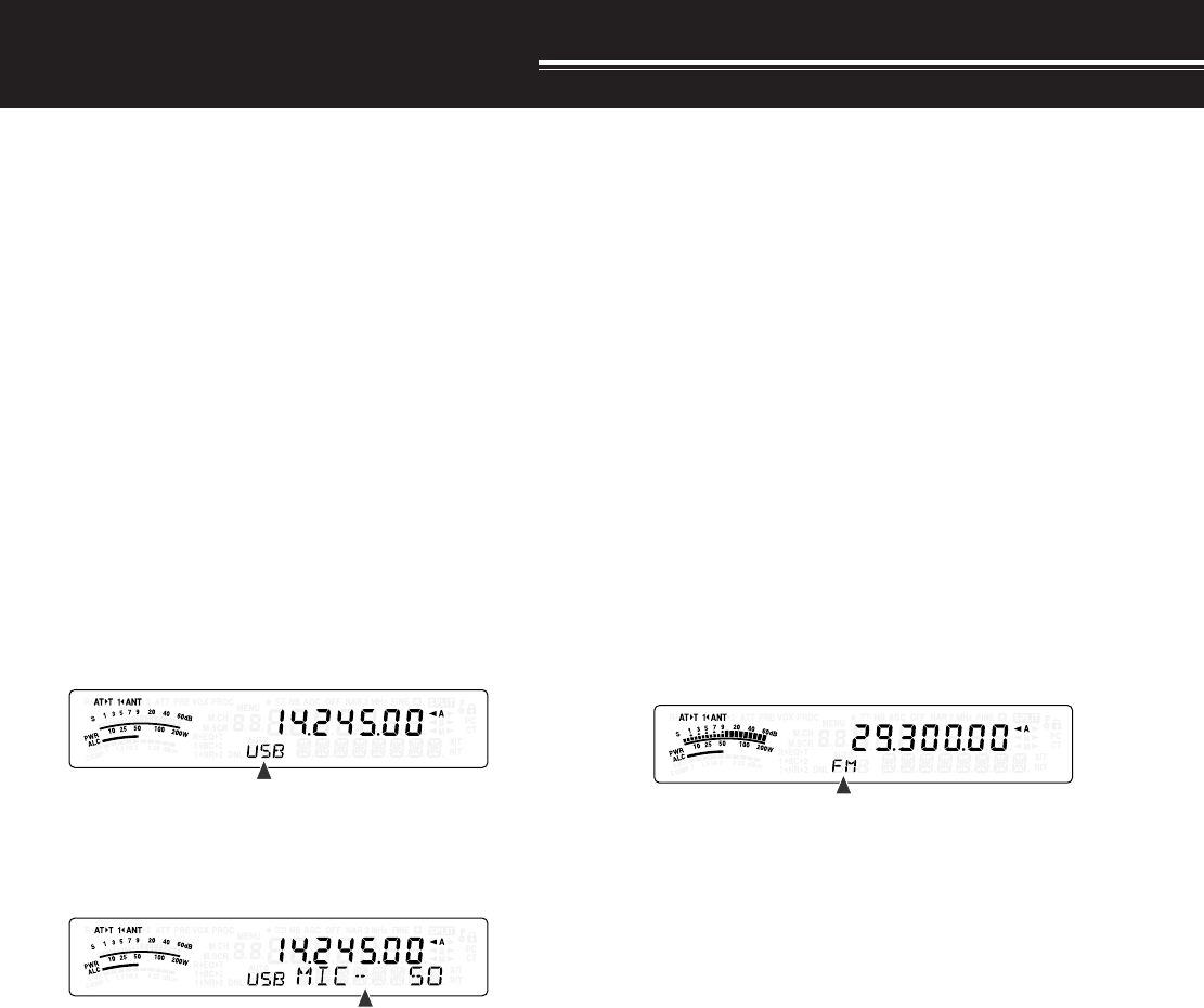
27
BASIC COMMUNICATIONS
SSB TRANSMISSION
SSB is the most commonly-used mode on the HF
Amateur radio bands. Compared with other voice
modes, SSB requires only a narrow bandwidth for
communications. SSB also allows long distance
communications with minimum transmission power.
If necessary, refer to “OPERATING BASICS”,
beginning on page 18, for details on how to receive.
1Select an operating frequency.
2Press [MODE] until “USB” or “LSB” appears on
the operating mode display.
• If the desired sideband (“USB” or “LSB”) does
not appear, select the other sideband first.
Then, press [MODE] (1 s). The mode indicator
changes to your desired sideband.
• “USB” represents the upper sideband and
“LSB” represents the lower sideband.
Normally, USB is used for the communications
for 10 MHz and above. While LSB is used for
the frequencies below 10 MHz.
3Press [MIC/ 5/ RF.G] to adjust the Microphone
gain.
• The current gain level appears on the sub-
display.
4Press and hold Mic [PTT].
• The LED above the [MODE] key lights red.
• Refer to “VOX” {page 36} for information on
automatic TX/ RX switching.
5Speak into the microphone and turn the
MULTI control so that the ALC meter reflects your
voice level but does not exceed the ALC limit.
• Speak in your normal tone and level of voice.
Speaking too close to the microphone or too
loudly may increase distortion and reduce
intelligibility at the receiving end.
• You may want to use the Speech Processor.
Refer to “SPEECH PROCESSOR” {page 37}
for details.
6Release Mic [PTT] to return to Reception mode.
• The LED lights green or turns off, depending
on the SQL control position.
7Press [MIC/ 5/ RF.G] to exit the Microphone gain
adjustment.
Refer to “COMMUNICATING AIDS”, beginning on
page 34, for information on additional useful
operation functions.
FM TRANSMISSION
FM is a common mode for communicating on VHF or
UHF frequencies. As for HF and the 6 m band,
29 MHz and 51-54 MHz bands are commonly used
for FM operation. You can also utilize 10 m/ 6 m band
repeaters to reach your friends when they are outside
or skipped over from your coverage. Although FM
requires a wider bandwidth when compared to SSB
or AM mode, it has the finest audio quality among
these modes. When combined with the full-quieting
aspect of FM signals, which suppress background
noise on the frequency, FM can be the best method
for maintaining casual communications with your
local friends.
If necessary, refer to “OPERATING BASICS”,
beginning on page 18, for details on how to receive.
1Select an operating frequency.
2Press [MODE] until “FM” appears.
• If “FM” does not appear, select “AM”, then
press [MODE] (1 s). The mode indicator
changes to “FM”.
3Press and hold Mic [PTT].
• The LED lights red.
• Refer to “VOX” for information on automatic
TX/ RX switching {page 36}.
4Speak into the microphone in your normal tone
and level of voice.
• Speaking too close to the microphone or too
loudly may increase distortion and reduce
intelligibility at the receiving end.
• You can switch the Microphone gain for FM
between 1 (Low), 2 (Medium), and 3 (High) by
using Menu No. 44. 1 (Low) is usually
appropriate; however, select 3 (High) if other
stations report that your modulation is weak.
5Release Mic [PTT] to return to Reception mode.
• The LED lights green or turns off, depending
on the SQL control position.
Refer to “COMMUNICATING AIDS”, beginning on
page 34, for additional information on useful
operation functions.
Note:
Microphone gain adjustment for SSB or AM has no effect in
FM mode. In FM mode, you must select 1 (Low), 2 (Medium), or
3 (High) in Menu No. 44.
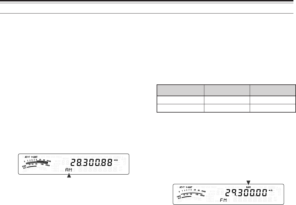
6 BASIC COMMUNICATIONS
28
AM TRANSMISSION
Each mode used on the HF Amateur bands has its
own advantages. Although long distance DX
contacts may be less common while using AM, the
superior audio quality characteristic of AM operation
is one reason why some hams prefer this mode.
When looking for others operating on AM, check the
following frequencies first:
3885 kHz, 7290 kHz, 14286 kHz, 21390 kHz, and
29000 ~ 29200 kHz
If necessary, refer to “OPERATING BASICS”,
beginning on page 18, for details on how to receive.
1Select an operating frequency.
2Press [MODE] until “AM” appears.
• If “AM” does not appear, select “FM” first, then
press [MODE] (1 s). The mode indicator
changes to “AM”.
3Press [MIC/ 5/ RF.G] to enter the Microphone gain
adjutment mode.
• The current gain level appears on the sub-
display.
4Press and hold Mic [PTT].
• The LED lights red.
• Refer to VOX function for information on
automatic TX/ RX switching {page 36}.
5Speak into the microphone and adjust the
MULTI control so that the power meter slightly
reflects your voice level.
• Speak in your normal tone and level of voice.
Speaking too close to the microphone or too
loudly may increase distortion and reduce
intelligibility at the receiving end.
• You may want to use the Speech Processor.
Refer to “SPEECH PROCESSOR” {page 37}
for details.
6Release Mic [PTT] to return to Reception mode.
• The LED lights green or turns off, depending
on the SQL control position.
7Press [MIC/ 5/ RF.G] to exit the Microphone gain
adjustment mode.
Refer to “COMMUNICATING AIDS”, beginning on
page 34, for information on additional useful
operation functions.
Note:
While transmitting, press
[MIC/ 5/ RF.G]
and then turn the
MULTI
control so that the ALC meter just begins to indicate. Press
[MIC/ 5/ RF.G]
again
to complete the adjustment.
NARROW BANDWIDTH FOR FM
Select wide band or narrow band TX deviation
depending on whether the other station is using wide
band or narrow band RX deviation. The table below
shows the RX IF filter bandwidth and TX deviation
combination for each operating mode. The
bandwidth selection is crucial to avoid audio distortion
or insufficient intelligibility that the other station will
encounter.
edoM retliFFIXR noitaiveDXT
MFworraNediW
RAN+MFworraNworraN
1Press [MODE] until “FM” appears.
• If “FM” does not appear, select “AM” first, then
press [MODE] (1 s). The mode indicator
changes to “FM”.
2Press [FIL/ NAR] (1 s) to toggle the selection
between wide and narrow TX deviation.
• “NAR” appears when the narrow TX deviation
is selected.
NARROW BANDWIDTH FOR AM
When receiving AM, you can further decrease the
bandwidth to eliminate interference. However, the
transmission deviation of AM is not affected by this
selection.
1Press [MODE] until “AM” appears.
• If “AM” does not appear, select “FM” first, then
press [MODE] (1 s). The mode indicator
changes to “AM”.
2Press [FIL/ NAR] (1 s) to toggle the selection
between Normal and Narrow.
• “NAR” appears when the narrow bandwidth is
selected for the AM reception.
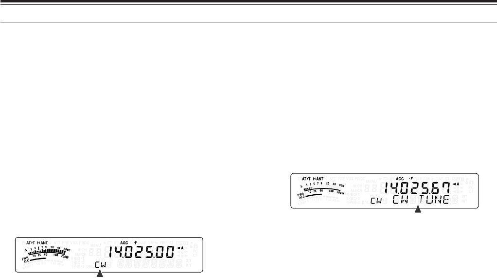
29
6 BASIC COMMUNICATIONS
CW TRANSMISSION
CW operators know that this mode is very reliable
when communicating under worst conditions. It may
be true that newer digital modes rival CW as being
equally as useful in poor conditions. These modes,
however, do not have the long history of service nor
the simplicity that CW provides.
This transceiver has a built-in electronic keyer that
supports a variety of functions. For details on using
these functions, refer to “ELECTRONIC KEYER”
{page 39}.
If necessary, refer to “OPERATING BASICS”,
beginning on page 18, for details on how to receive.
1Select the operating frequency.
2Press [MODE] until “CW” or “CWR” appears.
• To precisely tune in another station, use Auto
Zero-beat. Refer to “AUTO ZERO-BEAT”
{below}.
3Press [VOX/ 8] to activate the CW break-in
function.
• “VOX” appears.
• Refer to “CW BREAK-IN” for further information
on automatic TX/ RX switching {page 39}.
4Begin sending the message.
• As you transmit, you should hear a sidetone
that lets you monitor your own transmission.
• The LED lights red as you send the message.
5Stop sending the message to return to Reception
mode.
• The LED lights green or turns off, depending
on the SQL control setting.
AUTO ZERO-BEAT
Use Auto Zero-beat before transmitting to tune in a
CW station. Auto Zero-beat automatically and exactly
matches your transmit frequency with the station you
are receiving. Neglecting to do this will reduce your
chances of being heard by the other station.
1Tune to the CW signal using the Tuning control.
2Press [BC/ CW.T] (1 s) to start Auto Zero-beat
while CW is selected for the operating mode.
• “CW TUNE” appears.
• Your reception frequency automatically
changes so that the pitch (tone) of the received
signal exactly matches the TX sidetone/ RX
pitch frequency that you have selected. Refer
to “TX SIDETONE/ RX PITCH FREQUENCY”
{below}.
• When matching is completed, “CW TUNE”
disappears.
• If matching is unsuccessful, the previous
frequency is restored.
3To quit Auto Zero-beat, press [CLR/ MTR] or
press [BC/ CW.T] again.
Note:
◆
You cannot start Auto Zero-beat if you have selected 1.0 kHz or
wider for the DSP filter bandwidth {page 46}.
◆
When using Auto Zero-beat, the matching error is within
±
50 Hz
in most cases.
◆
Auto Zero-beat may fail if the keying speed of the target station is
too slow or some interference is present.
◆
When the RIT function is ON, only RIT frequencies change to
make the Auto Zero-beat adjustment.
TX SIDETONE/ RX PITCH FREQUENCY
As you send CW, you will hear tones from the
transceiver speaker. These are called TX
(transmission) sidetones. Listening to these tones,
you can monitor what you are transmitting. You may
also use the tones to ensure that your key contacts
are closing, the keyer is functioning, or to practice
sending without actually putting a signal on the air.
RX (reception) pitch refers to the frequency of CW
that you hear after tuning in a CW station.
On this transceiver, the frequency of the sidetone and
RX pitch are equal and selectable. Access Menu No.
34 to select the frequency that is most comfortable for
you. The selectable range is from 400 Hz to 1000 Hz
in steps of 50 Hz (default is 800 Hz).
To change the volume of the TX sidetone, access
Menu No. 13. The selections range from 1 to 9 and
OFF (default is 5).
Note:
The position of the
AF
control does not affect the volume of
the TX sidetone.
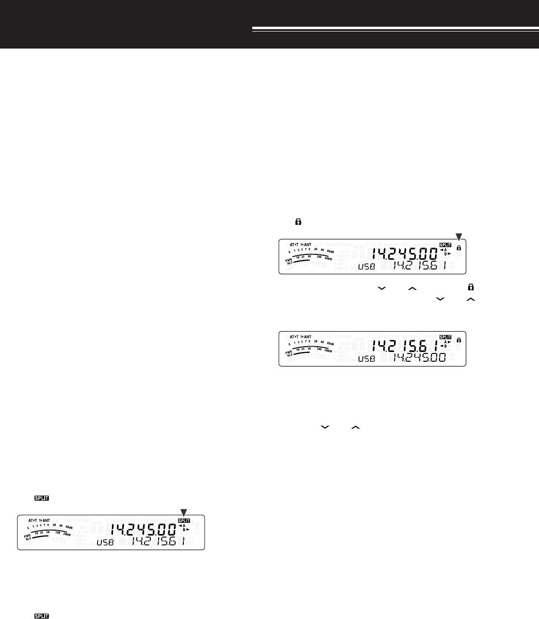
ENHANCED COMMUNICATIONS
30
SPLIT-FREQUENCY OPERATION
Usually you can communicate with other stations
using a single frequency for receiving and
transmitting. In this case, you select only one
frequency on either VFO A or VFO B. However, there
are cases where you must select one frequency for
receiving and a different frequency for transmitting.
This requires the use of 2 VFOs. This is referred to
as “split-frequency operation”. One typical case
which requires this type of operation is when you use
an FM repeater {page 31}. Another typical case is
when you call a rare DX station.
When a rare or desirable DX station is heard, that
operator may immediately get many simultaneous
responses. Often, such a station is lost under the
noise and confusion of many calling stations. If you
find that you are suddenly being called by many
operators, it is your responsibility to control the
situation. You may announce that you will be “listening
up 5 (kHz, from your present transmission frequency)”,
or “listening down between 5 and 10 (kHz)”.
1Press [A/B / M/V] to select VFO A or VFO B to
reception frequency.
•“tA” or “tB” appears to show which VFO is
selected.
2Select an operating frequency.
• The frequency selected at this point will be
used for transmission.
• To copy the selected VFO frequency to the
other VFO, press [A=B/ SPLIT].
3Press [A/B / M/V] to select the other VFO.
4Select an operating frequency.
• The frequency selected on this VFO will be
used for reception.
5Press [A=B/ SPLIT] (1 s).
•“ ” appears.
• Each time you press [A/B / M/V], the reception
and the transmission frequency are swapped.
6To quit split-frequency operation, press
[A=B/ SPLIT] (1 s) again.
•“ ” disappears.
TF-SET (TRANSMISSION FREQUENCY SET)
TF-SET allows you to temporarily switch your
transmission frequency and reception frequency.
Canceling this function immediately restores the
original transmission and reception frequencies.
By activating TF-SET, you can listen on your
transmission frequency, and change it while listening.
This allows you to check whether or not the newly
selected transmission frequency is free of interference.
1Configure split-frequency operation as explained
in the previous section.
2Press [MENU/ F.LOCK] (1 s) to lock the Tuning
control.
•“” appears.
3Press and hold either [ ] or [ ] while the “ ”
icon is visible. While holding down [ ] or [ ],
turn the Tuning control or press Mic [UP]/ [DWN]
to change the transmission frequency.
• The transceiver receives on the frequency as
you change, but the frequency shown on the
sub-display (the original reception frequency)
stays unchanged.
4Release [ ] or [ ].
• You are now receiving again on your original
reception frequency.
Successfully contacting a DX station in a pileup often
depends on making a well-timed call on a clear
frequency. That is, it is important to select a relatively
clear transmission frequency and to transmit at the
exact instant when the DX station is listening but the
majority of the groups aren’t transmitting. Switch
your reception and transmission frequencies by using
the TF-SET function and listen to your transmission
frequency. You will soon learn the rhythm of the DX
station and the pileup. The more proficient you
become at using this function, the more DX stations
you will contact.
Note:
◆
TF-SET is disabled while transmitting.
◆
An RIT offset frequency is not added; however, an XIT offset
frequency is added to the transmission frequency.
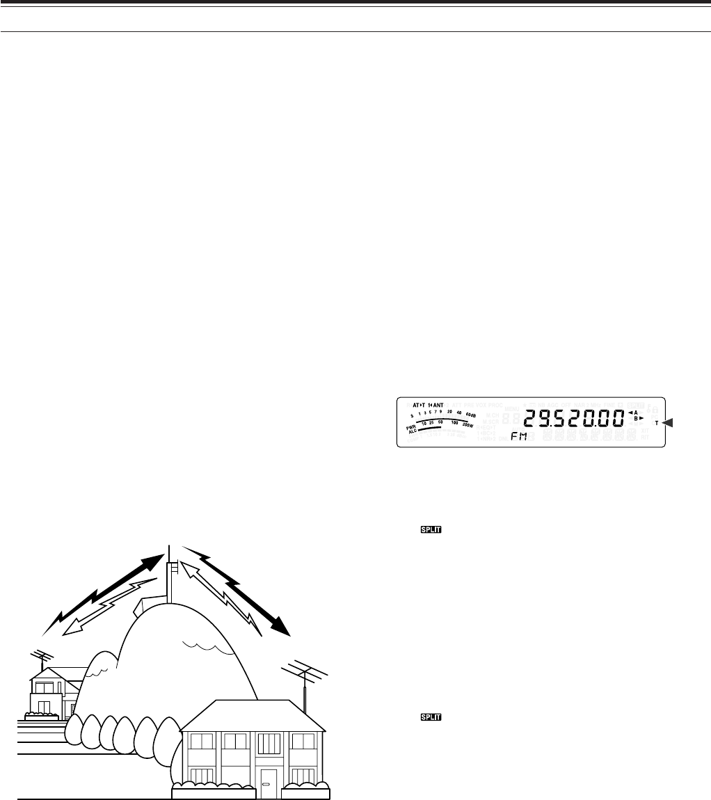
31
7 ENHANCED COMMUNICATIONS
FM REPEATER OPERATION
Most Amateur radio voice repeaters use a separate
reception and transmission frequency. The
transmission frequency may be higher or lower than
the reception frequency. In addition, some repeaters
may require the transceiver to transmit a subtone
before the repeater can be used.
Compared to simplex communication, you can
usually transmit over much greater distances by
using a repeater. Repeaters are typically located on
a mountain top or other elevated location. Often they
operate at higher ERP (Effective Radiated Power)
than a typical station. This combination of elevation
and high ERP allows communications over
considerable distances.
HF/ 6 m band repeaters operate usually in the
29 MHz FM sub-band and 51-54 MHz band. This
special service combines the advantages of FM
operation, good fidelity with noise and interference
immunity, with the excitement of HF DX (long
distance) communications. Even on a quiet day, 10
meter FM provides reliable around-town
communications with the potential for sudden DX
from across the country or around the world.
Note:
◆
When programming 2 separate frequencies using 2 VFOs, be
sure to select FM mode on both VFOs.
◆
When operating through a repeater, over deviation caused by
speaking too loudly into the microphone can cause your signal to
“talk-off” (break up) through the repeater.
1Press [A/B / M/V] to select VFO A or VFO B.
•“tA” or “tB” appears to show which VFO is
selected.
2Turn the Tuning control or MULTI control to select
the reception frequency.
3Press [MODE] to select FM mode {page 19}.
4Press [A=B/ SPLIT] to duplicate the frequencies
and other data to the other VFO.
5Turn the Tuning control or MULTI control to select
the transmission frequency.
• The frequency selected on this VFO will be
used for transmission.
6Press [NB/T/ 7] to turn the Tone function ON if the
repeater requires a subtone.
• “T” appears.
• Refer to “SELECTING SUBTONE
FREQUENCY” for more details on the subtone
{page 32}.
• To quit the Subtone function, press [NB/T/ 7]
twice.
7Press [A=B/ SPLIT] (1 s).
•“ ” appears.
8Press [A/B / M/V] to go back to the original
reception frequency.
9Press Mic [PTT] to transmit.
• The VFO changes to the other VFO to transmit.
• Each time you press [A/B / M/V], the reception
and the transmission frequency are swapped.
10 Press [A=B/ SPLIT] (1 s) to quit split-frequency
operation.
•“ ” disappears.
The data that you select in steps 1 to 8 can be stored
in memory. Refer to “Split-Frequency Channels”
{page 51}.
Note:
◆
When operating through a repeater, over deviation caused by
speaking too loudly into the microphone can cause your signal
to “talk-off” (break up) through the repeater.
◆
To check the subtone frequency stored in a memory channel,
recall the desired memory channel, and press
[NB/T/ 7] (1 s)
.
29.520 MHz
88.5 Hz
29.520 MHz
88.5 Hz
29.620 MHz
29.620 MHz
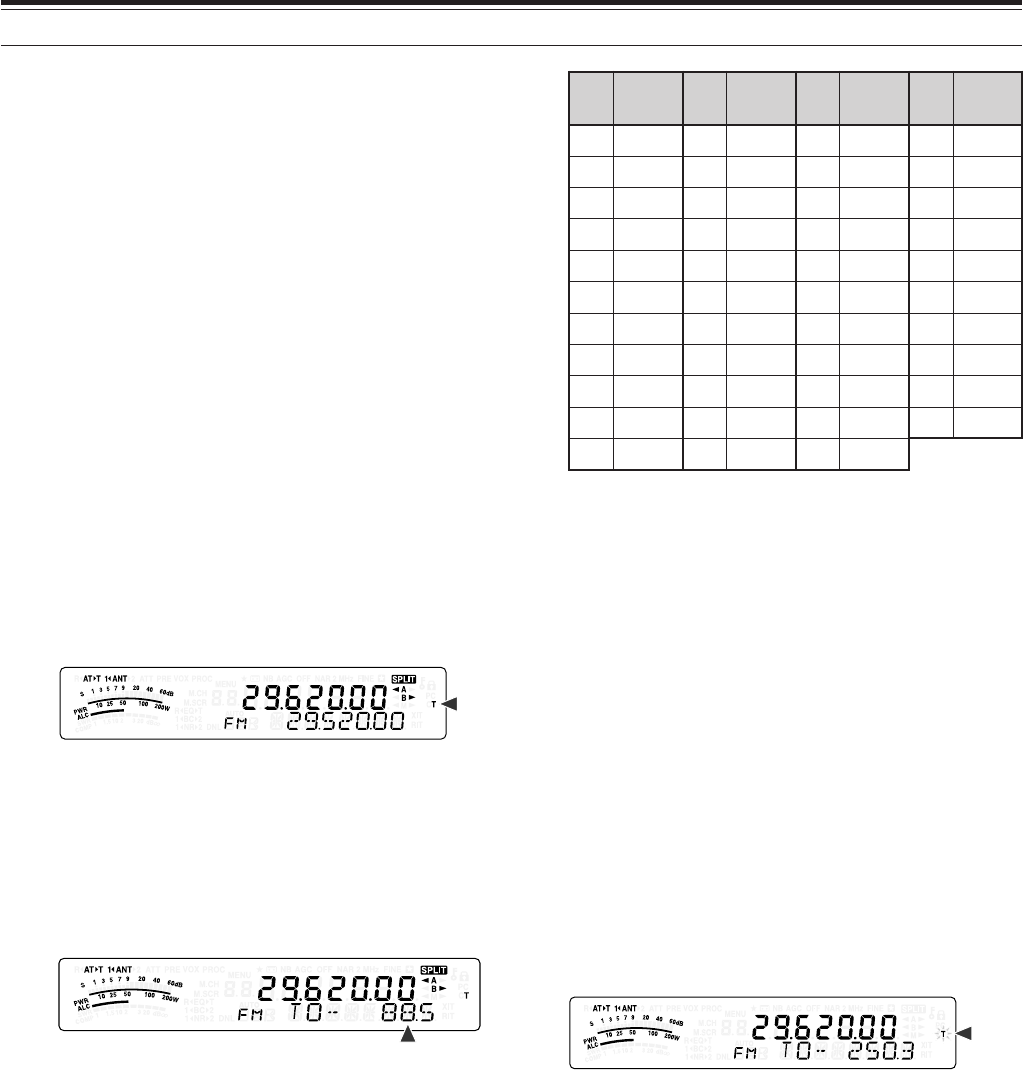
32
7 ENHANCED COMMUNICATIONS
TRANSMITTING A TONE
In general, FM repeaters require the transceiver to
transmit a sub-audible tone to prevent other
repeaters on the same frequency from locking each
other up. The required tone frequency differs among
repeaters. Repeaters also differ in their requirements
for either continuous or burst tones. For the
appropriate selections for your accessible repeaters,
consult your local repeater reference.
After completing the tone settings, pressing and
holding Mic [PTT] causes the transceiver to transmit
the selected tone. If you have selected a 1750 Hz
tone, the transceiver sends a 500 ms tone burst each
time transmission starts.
Note:
If you store tone settings in a memory channel, you need not
reprogram each time. Refer to “MEMORY FEATURES” {page 50}.
■Activating the Tone Function
1Confirm that FM mode has been selected on
the VFO(s) {page 19}.
• When using 2 VFOs, you must select FM
mode on both VFOs.
2Press [NB/T/ 7].
• “T” appears.
Note:
You cannot use the Tone function with the CTCSS
function.
■Selecting a Tone Frequency
1While “T” appears (Tone function is ON), press
[NB/T/ 7] (1 s).
• The current tone frequency appears.
The default is 88.5 Hz.
2Turn the MULTI control to select the desired
tone frequency.
• The available tone frequencies are listed in
the following table.
3Press [MTR/ CLR] to complete the setting.
.oN .qerF )zH( .oN .qerF )zH( .oN .qerF )zH( .oN .qerF )zH(
000.76114.79223.141335.602
103.96210.001322.641437.012
209.17315.301424.151531.812
304.47412.701527.651637.522
400.77519.011622.261731.922
507.97618.411729.761836.332
605.28718.811828.371938.142
704.58810.321929.971043.052
805.88913.721032.681141.452
905.19028.131138.291240571
018.49125.631235.302
Note:
◆
You can select a tone frequency independent of a CTCSS
frequency.
◆
When 1750 Hz is selected, the transceiver sends a 500 ms
tone burst each time transmission starts. You cannot
transmit 1750 Hz tone manually.
TONE FREQ. ID SCAN
This function scans through all tone frequencies to
identify the incoming tone frequency on a received
signal. You may find this useful when you do not
know the tone frequency that the repeater uses.
1While the Tone function is ON (“T” is visible),
press [NB/T/ 7] (1 s).
• The current tone frequency appears.
2Press [SCAN/ SG.SEL] to activate the Tone
frequency ID scan.
• “T” blinks and every tone frequency is scanned.
When the tone frequency is identified, the
transceiver stops scanning and the identified
frequency is displayed.
• Press [SCAN/ SG.SEL] to stop scanning while
the tone frequency ID scan is active.
• Press [SCAN/ SG.SEL] again to resume
scanning.
Note:
Received signals are audible while scanning is in progress.
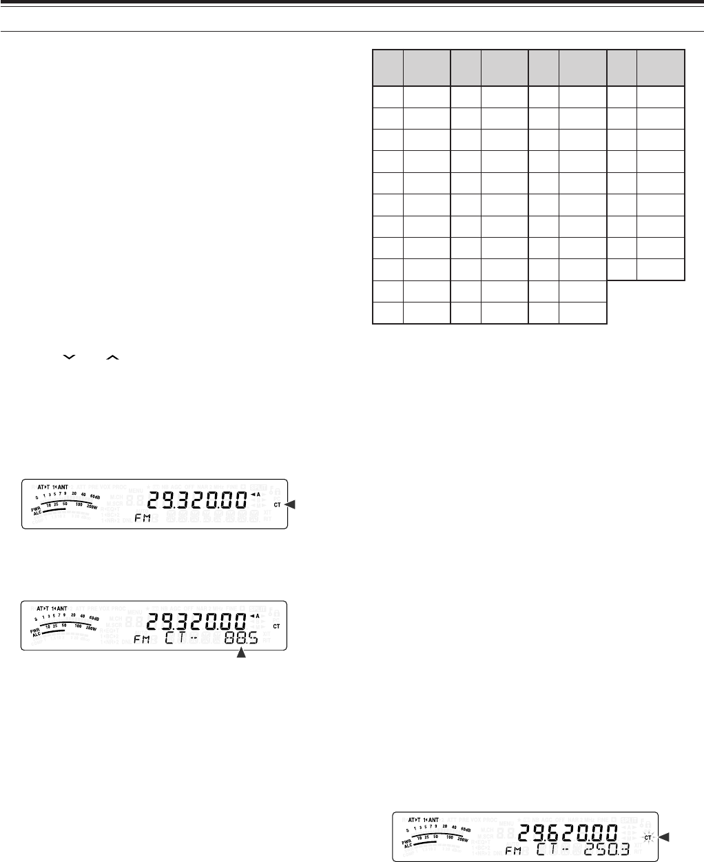
33
7 ENHANCED COMMUNICATIONS
FM CTCSS OPERATION
You may sometimes want to hear calls only from
specific persons. When using FM mode, the
Continuous Tone Coded Squelch System (CTCSS)
allows you to ignore (not hear) unwanted calls from
other persons who are using the same frequency.
A CTCSS tone is sub-audible and is selectable from
among the 42 tone frequencies. Select the same
CTCSS tone as the other stations in your group. You
will not hear calls from stations other than those using
the same CTCSS tone.
Note:
CTCSS does not cause your conversation to be private. It
only relieves you from listening to unwanted conversations.
1Press [A/B / M/V] to select VFO A or VFO B.
•“tA” or “tB” appears to show which VFO is
selected.
2Select the 29 MHz band or the 51-54 MHz band
using [ ] or [ ].
3Select the desired frequency with the Tuning
control or MULTI control.
4Press [MODE] to select FM mode {page 19}.
5Turn the SQL control to adjust the squelch.
6Press [NB/T/ 7] until “CT” appears.
7While “CT” is visible, press [NB/T/ 7] (1 s).
• The current CTCSS frequency appears.
The default CTCSS frequency is 88.5 Hz.
8Turn the MULTI control to select the appropriate
CTCSS frequency.
• The selectable CTCSS frequencies are listed in
the following table.
9Press [MTR/ CLR] to complete the setting.
.oN .qerF )zH( .oN .qerF )zH( .oN .qerF )zH( .oN .qerF )zH(
000.76114.79223.141335.602
103.96210.001322.641437.012
209.17315.301424.151531.812
304.47412.701527.651637.522
400.77519.011622.261731.922
507.97618.411729.761836.332
605.28718.811828.371938.142
704.58810.321929.971043.052
805.88913.721032.681141.452
905.19028.131138.291
018.49125.631235.302
You will hear calls only when the selected tone is
received. To answer the call, press and hold Mic
[PTT], then speak into the microphone.
Skip steps 7 and 8 if you have already programmed
the appropriate CTCSS frequency.
Note:
◆
When using split-frequency operation, select FM mode on both
VFOs to use CTCSS.
◆
You can select a CTCSS frequency independent of a tone
frequency.
◆
You cannot use the CTCSS function with the Tone function.
CTCSS FREQUENCY ID SCAN
This function scans through all CTCSS frequencies to
identify the incoming CTCSS frequency on a received
signal. You may find this useful when you cannot
recall the CTCSS frequency that the other persons in
your group are using.
1While the CTCSS function is ON, press [NB/T/ 7]
(1 s).
• The current CTCSS frequency appears.
2Press [SCAN/ SG.SEL] to activate the CTCSS
frequency ID scan.
• “CT” blinks and every CTCSS frequency is
scanned. When the CTCSS frequency is
identified, the transceiver stops scanning and
the identified frequency is displayed.
• Press [SCAN/ SG.SEL] again to resume
scanning.
• Press [SCAN/ SG.SEL] to stop scanning while
the CTCSS frequency ID scan is active.
Note:
Received signals are audible while scanning is in progress.
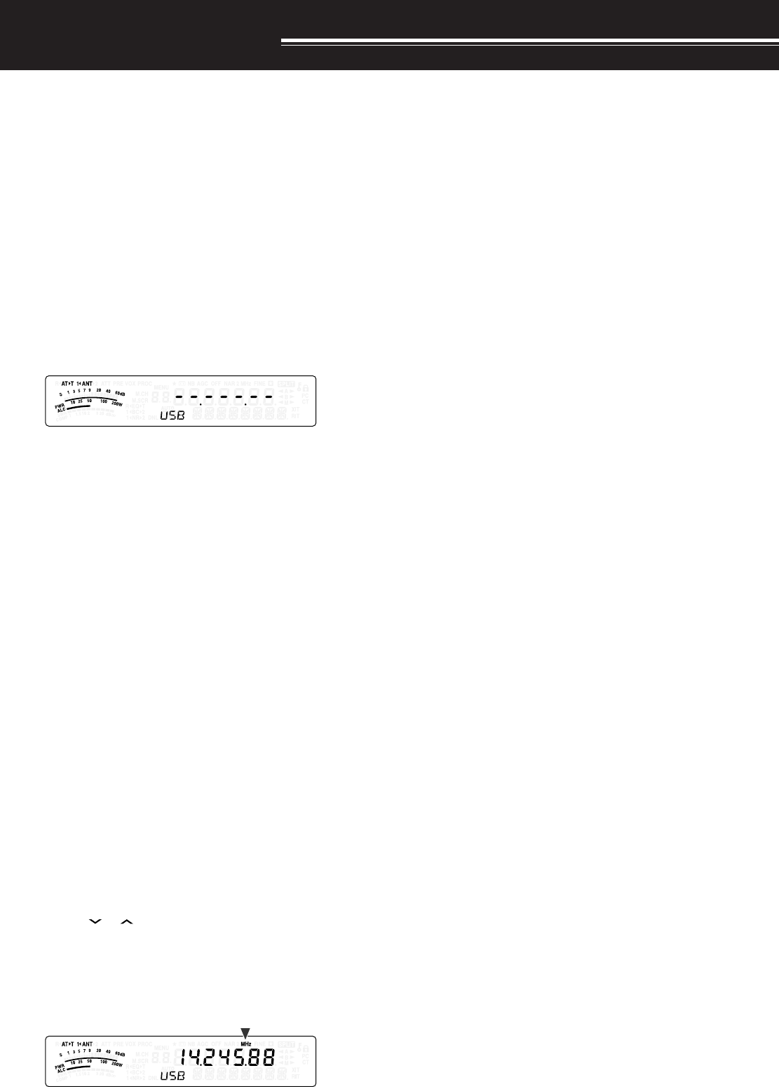
COMMUNICATING AIDS
34
RECEPTION
SELECTING YOUR FREQUENCY
In addition to turning the Tuning control or pressing
Mic [UP]/ [DWN], there are several other ways to
select your frequency. This section describes
additional methods of frequency selection that may
save you time and effort.
■Direct Frequency Entry
When the desired frequency is far removed from
the current frequency, directly entering a
frequency from the numeric keypad is usually the
fastest method.
1Press [ENT].
• “ - - . - - - . - - ” appears.
2Press the numeric keys ([0] to [9]) to enter
your desired frequency.
• Pressing [ENT] at any time fills the
remaining digits (the digits you did not
enter) with 0 and completes the entry.
To select 1.85 MHz for example, press
[ENT], [0], [1], [8], [5], then press [ENT] to
complete the input (6 key strokes).
• Pressing [MTR/ CLR] before pressing
[ENT] cancels the entry and restores the
current VFO frequency.
Note:
◆
You can enter a frequency in the range of 30.00 kHz to
59.999.99 MHz. Refer to the specifications for the
available frequency range.
◆
Attempting to enter a frequency that is outside the
selectable frequency range causes an alarm to sound.
The entered frequency is rejected.
◆
When the entered frequency does not meet the current
VFO frequency step size requirement, the nearest
available frequency is automatically selected after the
entered frequency is changed.
◆
When the 10 Hz digit (last displayed digit) is entered, the
digit 0 is automatically entered for the 1 Hz digit, and
frequency entry is completed. The 1 Hz digit is not
displayed.
◆
When an entered frequency is accepted, RIT or XIT will be
switched OFF, but the RIT or XIT offset frequency is not
cleared.
■Using the MHz key
Pressing [ ]/ [ ] on the Remote Control panel
changes Amateur bands. You can also use the
MULTI control to change the operating frequency
in steps of 1 MHz.
1Press [MHz].
• “MHz” appears.
2Turn the MULTI control.
• Clockwise increases the frequency and
counter-clockwise decreases the frequency.
3Press [MHz] again to exit.
• “MHz” disappears.
If you prefer to change the frequency in steps of
100 kHz or 500 kHz rather than 1 MHz, press
[MHz] (1 s), then turn the MULTI control to select
100 kHz, 500 kHz, or 1 MHz.
Note:
Even if 100 kHz or 500 kHz is assigned for the
[MHz]
key,
“MHz” appears on the display.
■Quick QSY
To move up or down the frequency quickly, use the
MULTI control. Turning this control changes the
operating frequency in steps of 5 kHz for SSB/
CW/ AM/ FSK and 10 kHz for FM.
• If you want to change the default frequency
step size, press [FINE/ STEP] (1 s). Turn the
MULTI control to select 5 kHz, 6.25 kHz, 10
kHz, 12.5 kHz, 15 kHz, 20 kHz, 25 kHz, 30
kHz, 50 kHz or 100 kHz for FM/ AM, and 500
Hz, 1 kHz, 2.5 kHz, 5 kHz, or 10 kHz for the
other modes. The default step size is 5 kHz for
SSB/ CW/ FSK/ AM and 10 kHz for FM.
• When changing the operating frequency by
using the MULTI control, frequencies are
rounded such that new frequencies are
multiples of the frequency step size. To disable
this function, access Menu No. 05 and select
“oFF” (default is “on”).
• Within the AM broadcast band, the step size
automatically defaults to the frequency step
value in Menu No. 06. This step size can be
switched between 9 kHz (all E-types: “on”) and
5 kHz (K-type: “oFF”) via Menu No. 06.
Note:
The programmed frequency step size for the
MULTI
control is stored independently for the HF and 50 MHz bands.
You can also set a different frequency step size for SSB/ CW/
FSK, AM and FM modes.
■Configuring the Tuning Control as MULTI control
(FM)
In FM mode, you can configure the Tuning control
to change the frequency as same as the MULTI
control. Access Menu No. 04 and select “on”
(default is “oFF”). O yu turn the Tuning control,
the frequency changes as same as turning the
MULTI control.
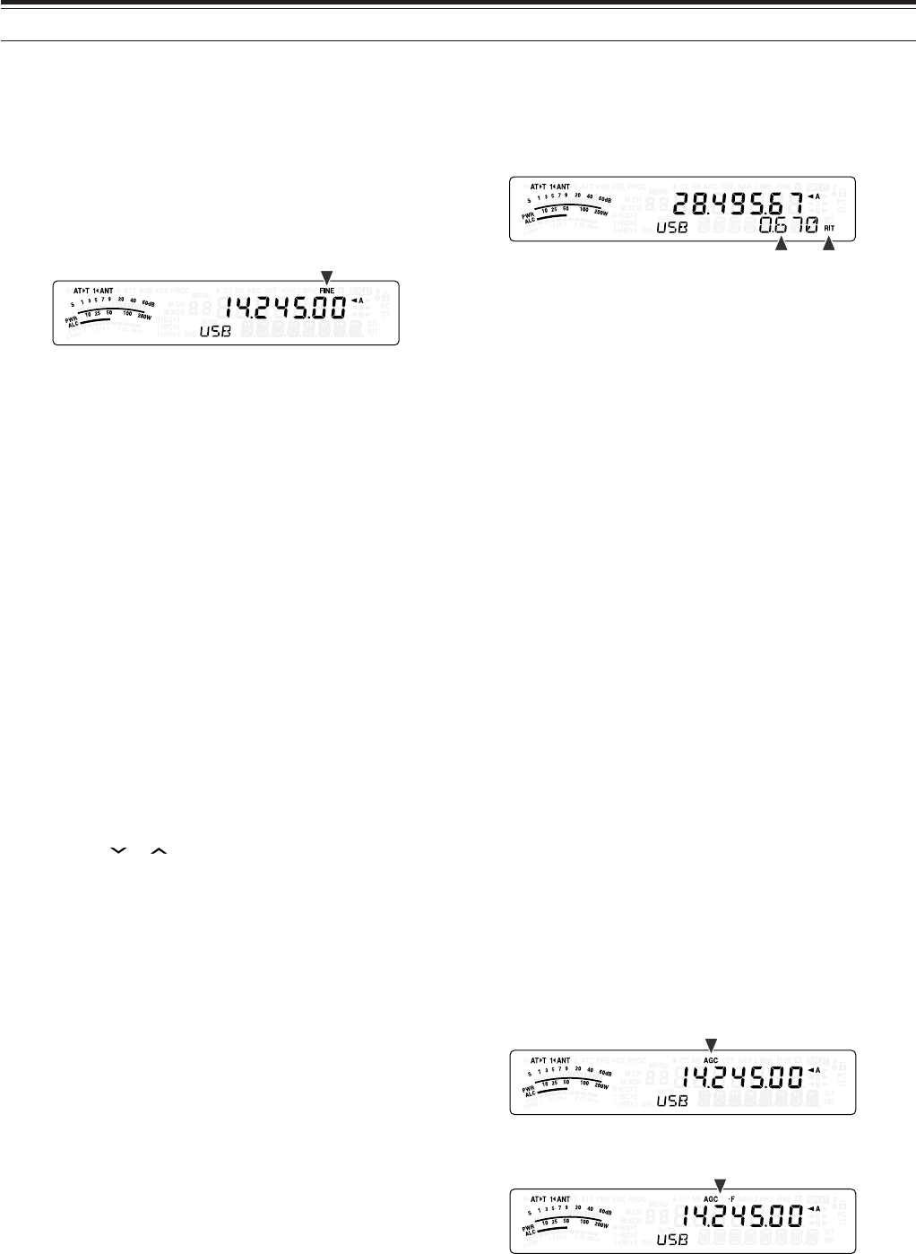
35
8 COMMUNICATING AIDS
■Fine Tuning
The default frequency step size when turning the
Tuning control to change the frequency is 10 Hz
for SSB, CW, and FSK modes, and 100 Hz for FM
and AM modes. However, you can change the
frequency step size to 1 Hz for SSB, CW, and FSK
modes, and 10 Hz for FM and AM modes.
1Press [FINE/ STEP].
• “FINE” appears.
2Turn the Tuning control to select the exact
frequency.
3To quit the function, press [FINE/ STEP] again.
• “FINE” disappears.
■Tuning control adjustment rate
The default Tuning control adjustment rate is
“500”. This represents the number of pulses the
Tuning control generates in a complete revolution.
Each pulse changes the tuning frequency based
on the current frequency step size (the frequency
step size for the Tuning control is 10 Hz for SSB/
CW/ FSK mode and 100 Hz for AM/ FM mode).
For example, in SSB mode the freqency step size
is 10 Hz, so the frequency would change by
5,000 Hz in a complete revolution of the Tuning
control. The adjustment rate of the Tuning control
can be lowered to “250” pulses per revolution or
increased to “1000” pulses per revolution.
1Press [MENU/ F.LOCK].
2Turn the MULTI control to select Menu No. 4.
3Press [ ]/ [ ] to select “250”, “500” (default),
or “1000”.
4Press [MENU/ F.LOCK] to store the setting
and exit Menu mode.
■Equalizing VFO Frequencies (A=B)
This function allows you to copy the frequency and
modulation mode of the active VFO to the inactive
VFO.
1Select the frequency and mode on VFO A or
VFO B.
2Press [A=B/ SPLIT].
• The frequency and mode selected in step 1
are duplicated to the inactive VFO.
3Press [A/B / M/V] to confirm that the frequency
was copied.
RIT (RECEIVE INCREMENTAL TUNING)
RIT provides the ability to change your reception
frequency by ±9.99 kHz in steps of 10 Hz without
changing your transmission frequency. If the Fine
Tuning ([FINE/ STEP]) function is ON, the step size
becomes 1 Hz. RIT works equally well with all
modulation modes and while using VFO or Memory
Recall mode.
1Press [RIT].
•“RIT” and the RIT offset appear.
2If required, press [CL] to reset the RIT offset to 0.
3Turn the RIT/ XIT control to change your reception
frequency.
4To turn RIT OFF, press [RIT].
• The reception frequency is returned to the
frequency that was selected prior to step 1.
Note:
When storing the frequency in a Memory channel with the RIT
function ON, the RIT offset frequency is added or subtracted to/ from
the VFO frequency. The calculated data is then stored in the Memory
channel.
AGC (AUTOMATIC GAIN CONTROL)
When using a mode other than FM, AGC selects the
time constant for the Automatic Gain Control circuit.
Selecting a slow time constant will cause the receiver
gain and S-meter readings to react slowly to large
input changes. A fast time constant causes the
receiver gain and the S-meter to react quickly to
changes in the input signal. A fast AGC setting is
particularly useful in the following situations:
• Tuning rapidly
• Receiving weak signals
• Receiving high-speed CW
For your convenience, the following default AGC time
constant has already been programmed.
SSB: Slow (“AGC”) CW: Fast (“AGC - F”)
FSK: Fast (“AGC - F”) AM: Slow (“AGC”)
To change the default time constant:
1Press [AGC/ 0/ OFF].
• The AGC time constant icon appears on the
display (“AGC”: Slow, “AGC - F”: Fast).
• Each time you press [AGC/ 0/ OFF], the AGC
time constant alternates fast and slow.
2If you want to turn the AGC OFF, press
[AGC/ 0/ OFF] (1 s).
• “AGC OFF” appears on the display.
Note:
You cannot adjust the AGC time constant in FM mode.
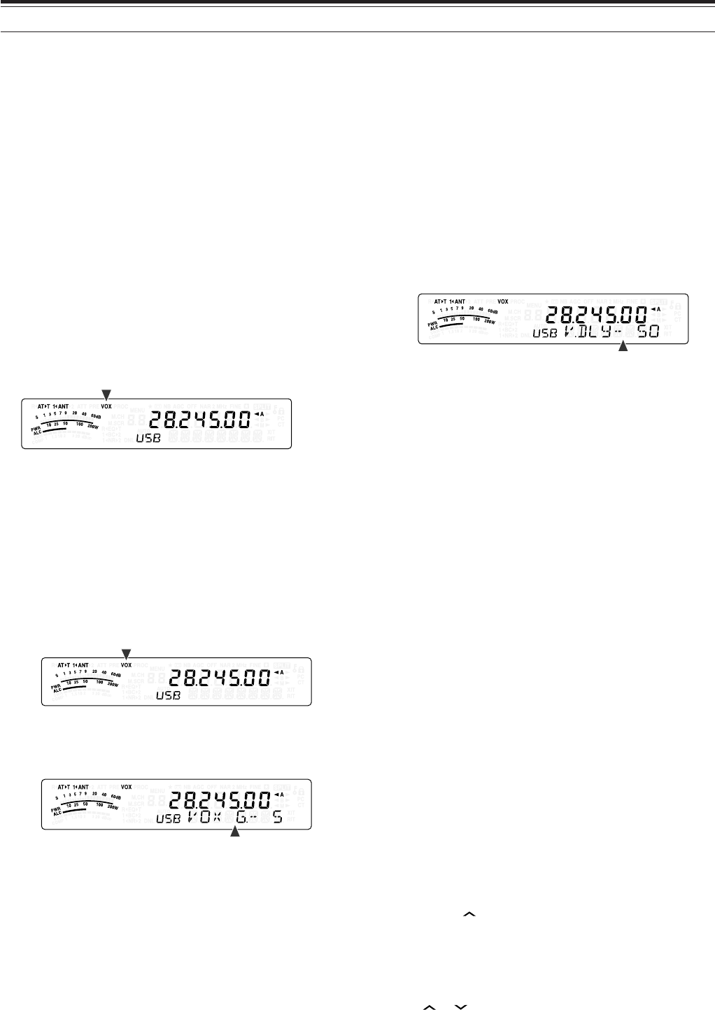
36
8 COMMUNICATING AIDS
TRANSMISSION
VOX (VOICE-OPERATED TRANSMIT)
VOX eliminates the necessity of manually switching
to the transmission mode each time you want to
transmit. The transceiver automatically switches to
transmission mode when the VOX circuitry senses
that you have begun speaking into the microphone.
When using VOX, develop the habit of pausing
between thoughts to allow the transceiver to drop
back to reception mode briefly. You will then hear if
anybody wants to interrupt, plus you will have a short
period to gather your thoughts before speaking again.
Your listeners will appreciate your consideration as
well as respect your more articulate conversation.
VOX can be switched ON and OFF independently for
CW and the other modes, excluding FSK.
Press [VOX/ 8] to toggle between VOX ON and OFF.
• “VOX” appears when the VOX function is ON.
■Microphone Input Level
To enjoy the VOX function, take the time to
properly adjust the gain of the VOX circuit. This
level controls the capability of the VOX circuit to
detect the presence or absence of your voice.
In CW mode, this level cannot be adjusted.
1Select USB, LSB, FM, or AM mode.
2Press [VOX/ 8] to switch the VOX function ON.
• “VOX” appears.
3Press [VOX/ 8] (1 s).
• The current VOX gain appears on the sub-
display.
4While speaking into the microphone using your
normal tone of voice, adjust the setting (default
is 4) using the MULTI control until the
transceiver reliably switches to transmission
mode each time you speak.
• The selectable gain range is from 0 to 9.
• The setting should not allow background
noise to switch the transceiver to transmit
mode.
Note:
The VOX gain level can be adjusted even if VOX is
switched OFF or while you are transmitting.
■Delay Time
If the transceiver returns to reception mode too
quickly after you stop speaking, your final word
may not be transmitted. To avoid this, select an
appropriate delay time that allows all of your
words to be transmitted without an overly long
delay after you stop speaking.
1Select USB, LSB, FM, or AM mode.
2Press [VOX/ 8] to switch the VOX function ON.
• “VOX” appears.
3Press [KEY/ DELAY] (1 s).
• The current setting appears on the sub-
display. The default is 50 (1500 ms).
4While speaking into the microphone using your
normal tone of voice, turn the MULTI control
such that the transceiver switches to reception
mode after you have stopped talking.
• The selectable range is from 5 to 100
(150 ms to 3000 ms) in steps of 5, or OFF.
5Press [MTR/ CLR] to store the parameter and
exit the setting mode.
■Anti-VOX adjustment
The TS-480 transceiver has a DSP IC to improve
and customize incoming/ outgoing audio signals.
When VOX function is turned ON, the DSP IC
adjusts the Anti-VOX level automatically,
comparing the reception sound level and
microphone input level. So, you never have to
worry about adjusting the anti-VOX level.
■VOX Source
Although microphone is normally used to perform
the VOX transmission, you can also utilize AF
input of the DATA connector (pin 1) on the TX/ RX
unit {page 81}. When the transceiver detects the
audio signal on the pin 1 of DATA connector, the
transceiver automatically transmits.
1Select USB, LSB, FM, or AM mode.
2Press [VOX/ 8] to switch the VOX function ON.
• “VOX” appears.
3Press [MENU/ F.LOCK] and turn MULTI
control to select Menu No. 60.
4Press [ ] to switch the VOX with DATA input
function ON.
5Turn MULTI control to select Menu No. 46.
6While sending AF signal to pin 1 of DATA
connector, adjust the value (default is 4) using
[ ]/ [ ] until the transceiver reliably switches
to transmit mode each time you send AF signal
to pin 1 of DATA connector.
Note:
VOX function does not work even if you speak into the
microphone. However, you can transmit with the Mic
[PTT]
.
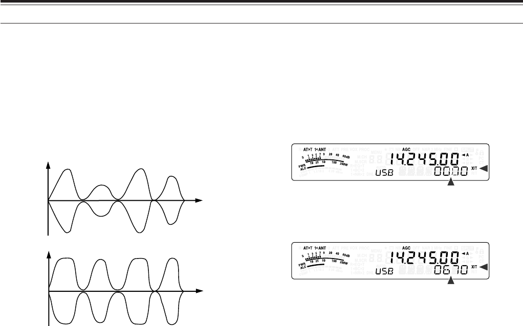
37
8 COMMUNICATING AIDS
SPEECH PROCESSOR
The Speech Processor levels out large fluctuations in
your voice while you speak. When using SSB, FM, or
AM mode, this leveling action effectively raises the
average TX power, resulting in a more
understandable signal. The amount of voice
compression is fully adjustable. You will notice that
using the Speech Processor makes it easier to be
heard by distant stations.
1Select USB, LSB, FM, or AM mode.
2Press [PROC/ 9] to turn the Speech Processor
ON.
• “PROC” appears.
3Press [PROC/ 9] (1 s) to enter the Speech
Processor input level adjustment mode.
4As you speak into the microphone, turn the
MULTI control so that the compression meter
indicates that the compression level is around
10 dB while you speak.
• Using higher compression will not improve your
signal clarity or apparent signal strength.
Excessively compressed signals are more
difficult to understand due to distortion and are
less pleasant to hear than signals with less
compression.
5Press [PROC/ 9] (1 s) to exit the Speech
Processor input level adjustment mode.
6Press [MIC/ 5/ RF.G] to enter the Speech
Processor output level adjustment mode.
• As you speak into the microphone, turn the
MULTI control so that the ALC meter reflects
according to your voice level but does not
exceed the ALC limit. Press [MIC/ 5/ RF.G] to
exit when you finish the adjustment mode.
XIT (TRANSMIT INCREMENTAL TUNING)
Similar to RIT, XIT provides the ability to change your
transmission frequency by ±9.99 kHz in steps of 10 Hz
without changing your reception frequency. If the Fine
Tuning function is ON, the frequency step size
becomes 1 Hz.
1Press [XIT].
• “XIT” and the XIT offset appear.
2If required, press [CL] to reset the XIT offset to 0.
3Turn the RIT/ XIT control to change your transmit
frequency.
4To turn XIT OFF, press [XIT].
• “XIT” and offset frequency display disappear.
The transmission frequency is returned to the
frequency that was selected prior to step 1.
Note:
◆
If the Fine Tuning function is ON, you can adjust the frequency
within
±
9.99 kHz.
◆
The frequency shift set by the
XIT
control is also used by the RIT
function. Therefore, changing or clearing the XIT offset also
affects the RIT offset.
◆
When the XIT frequency exceeds the limit of available
transmission frequency, the transceiver automatically stops
transmitting.
TX power
TX power
Time
Time
Speech
Processor
OFF
Speech
Processor
ON
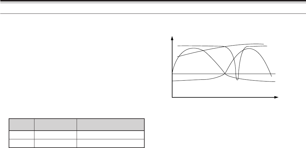
38
8 COMMUNICATING AIDS
CUSTOMIZING TRANSMISSION SIGNAL
CHARACTERISTICS
The quality of your transmission signal is important,
regardless of which on-air activity you pursue.
However, it is easy to be casual and overlook this fact
since you don’t listen to your own signal.
The following sub-sections provide information that
will help you tailor your transmission signal.
■TX Filter Bandwidth (SSB/ AM)
Use Menu No. 20 to select one of the following TX
filter bandwidths: 2.0 kHz or 2.4 kHz (default).
yalpsiD htdiwdnaB ycneuqerfdnabssaP
0.2zHk0.2zH0052~005
4.2zHk4.2zH0072~003
■TX Equalizer (SSB/ FM/ AM)
Use Menu No. 19 to change the transmission
frequency characteristics of your signal. You can
select from one of 6 different transmission profiles
including the default flat response. Selecting any of
the following items from the Menu causes “EQ
ss
ss
s
T”
to appear on the display.
• Off (oFF):
The default frequency response for SSB, FM,
and AM.
• High boost 1 (Hb1)/ High boost 2 (Hb2):
Emphasizes higher audio frequencies; effective
for a bassy voice. High boost 2 does not
reduce the low frequency as much as High
boost 1.
• Formant pass (FP):
Improves clarity by suppressing audio
frequencies outside the normal voice frequency
range.
• Bass boost 1 (bb1)/ Bass boost 2 (bb2):
Emphasizes lower audio frequencies; effective
for a voice with more high frequency
components. Bass boost 2 emphasises more
low frequency response.
• Conventional (c):
Emphasizes by 3 dB frequencies at 600 Hz
and higher.
• User (U):
Reserved for the optional ARCP software.
Off is programmed at the factory as a default.
Frequency Response Curves
TRANSMIT INHIBIT
Transmit Inhibit prevents the transceiver from being
placed in transmission mode. No signal can be
transmitted when this function is ON even if Mic [PTT]
is pressed.
• TX Inhibit OFF: Transmission is allowed.
• TX Inhibit ON: Transmission is not allowed.
Switch the function ON or OFF via Menu No. 55.
The default is OFF.
BUSY LOCKOUT
Busy Lockout prevents the transceiver from being
placed in transmit mode. Transmission is not allowed
if the current operating frequency is busy (in other
words, the squelch is open).
• Busy Lockout OFF: Transmission is allowed.
• Busy Lockout ON: Transmission is not allowed.
Switch the function ON or OFF via Menu No. 58.
The default is OFF.
CHANGING FREQUENCY WHILE TRANSMITTING
Moving your frequency while transmitting is usually
an unwise practice due to the risk of interfering with
other stations. However, if necessary, by using the
Tuning control you can change the operating
frequency while transmitting. You also can change
the XIT offset frequency while in transmission mode.
While transmitting, if you select a frequency outside
the transmission frequency range, the transceiver is
automatically forced to return to the reception mode.
If you selected transmission mode by pressing Mic
[PTT], transmission will not resume until you select a
frequency inside the transmission frequency range, at
which time you must release and press Mic [PTT]
again.
0.7 2.2
Amplitude
Audio
frequency
(kHz)
Bass boost
High boost
Off
Conventional
Formant pass
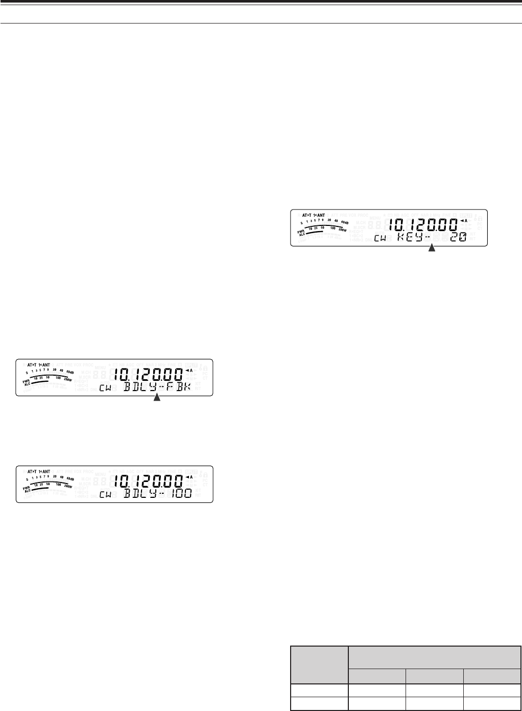
39
8 COMMUNICATING AIDS
CW BREAK-IN
Break-in allows you to transmit CW without manually
switching between transmission and reception
modes. Two types of Break-ins are available: Semi
Break-in and Full Break-in.
Semi Break-in:
When the key contacts open, the transceiver
automatically waits for the passage of the time period
that you have selected. The transceiver then returns
to reception mode.
Full Break-in:
As soon as the key contacts open, the transceiver
returns to reception mode.
USING SEMI BREAK-IN OR FULL BREAK-IN
1Press [MODE] until you select CW mode.
• “CW” or “CWR” appears.
2Press [VOX/ 8].
• “VOX” appears.
3Press [KEY/ 6/ DELAY] (1 s).
• The current setting (Full or delay time)
appears. The default is FBK (Full Break-in).
4Turn the MULTI control to select FBK (Full
Break-in) or a delay time for Semi Break-in.
• Delay time ranges from 5 to 100 (50 ms to
1000 ms) in steps of 5.
5Begin sending.
• The transceiver automatically switches to
transmission mode.
•When FBK (Full Break-in) is selected:
The transceiver immediately switches to
reception mode when the key opens.
•When a delay time is selected:
The transceiver switches to reception mode
after the delay time that you have selected has
passed.
6Press [MTR/ CLR] to exit.
Note:
Full Break-in cannot be used with the TL-922/ 922A linear
amplifier.
ELECTRONIC KEYER
This transceiver has a built-in electronic keyer that
can be used by connecting a keyer paddle to the
transceiver’s rear panel. Refer to “Keys for CW
(PADDLE and KEY)” {page 7} for details regarding
this connection. The built-in keyer supports lambic
(squeeze) operation.
CHANGING KEYING SPEED
The keying speed of the electronic keyer is fully
adjustable. Selecting the appropriate speed is
important in order to send error-free CW that other
operators can copy solidly. Selecting a speed that is
beyond your keying ability will only result in mistakes.
You will obtain the best results by selecting a speed
that is close to the speed used by the other station.
1Press [MODE] until you select CW mode.
• “CW” or “CWR” appears.
2Press [KEY/ 6/ DELAY].
• The current keying speed appears. The default
is 20 (WPM).
3While keying the paddle and listening to the TX
(transmission) sidetone, turn the MULTI control to
select the appropriate speed.
• The speeds range from 10 (WPM) to 60 (WPM),
in steps of 1 (WPM). The larger the number, the
faster the speed.
4Press [KEY/ 6/ DELAY] again to complete the
setting.
Note:
When using the semi-automatic “Bug” function, the selected
speed applies only to the rate that dots are sent.
AUTO WEIGHTING
The electronic keyer can automatically change the
dot/ dash weighting. Weighting is the ratio of dash
length to dot length. The weighting changes with
your keying speed, thus making your keying easier
for other operators to copy.
Access Menu No. 35 to select “auto” or “2.5” ~ “4.0”
(in steps of 0.1) fix weight ratio. The default is “auto”.
When the fix weight ratio is selected, the dot/ dash
weight ratio is locked regardless of the keying speed.
■Reverse Keying Weight Ratio
Auto Weighting increases the weighting as you
increase your keying speed. However, the
electronic keyer also can decrease the weighting
as you increase your keying speed.
To switch this function ON, access Menu No. 36,
and select “on”. The default is OFF.
esreveR gniyeK thgieW
)MPW(deepSgniyeK
52~01 54~62 06~64
FFO8.2:10.3:12.3:1
NO2.3:10.3:18.2:1
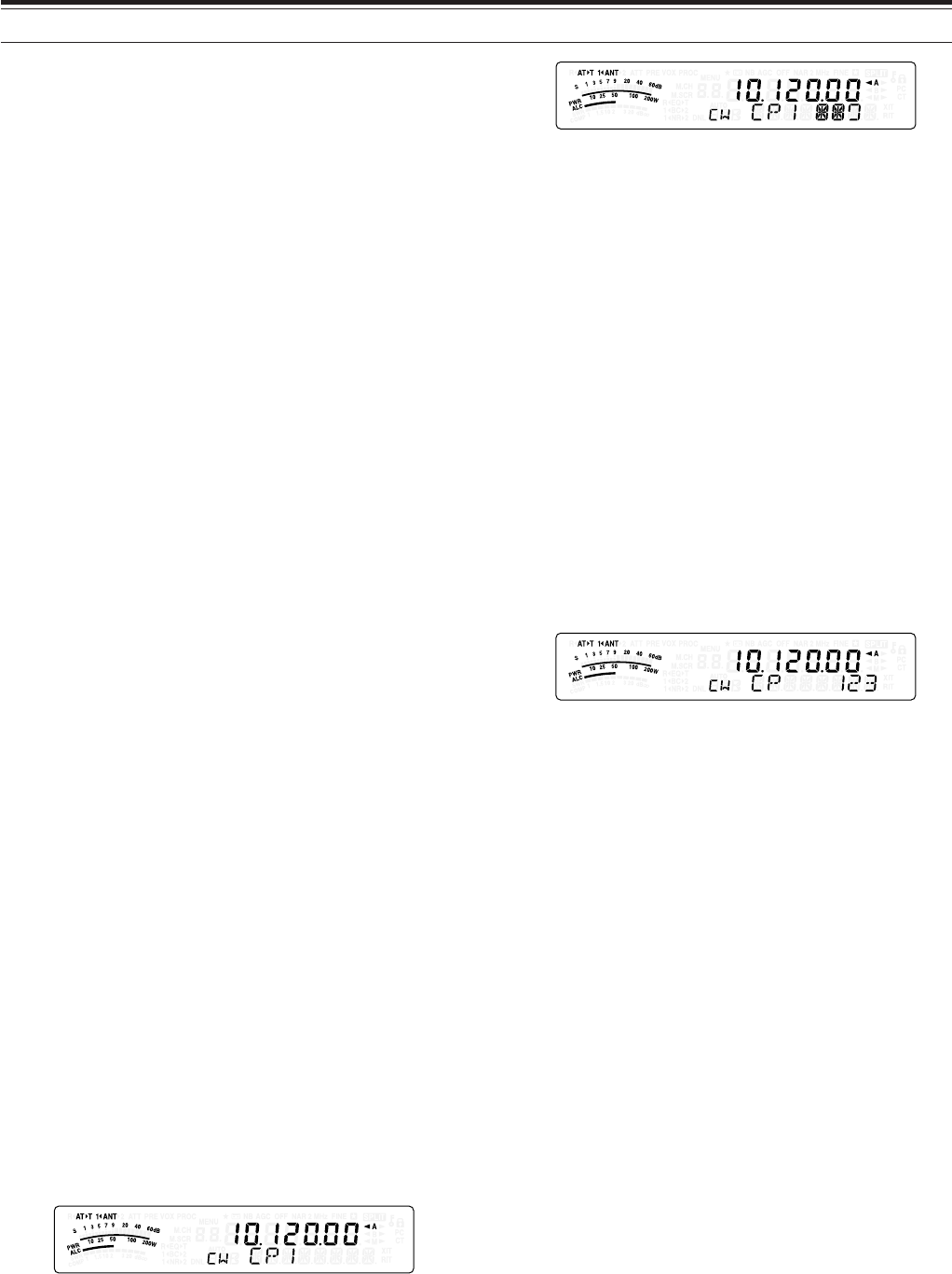
40
8 COMMUNICATING AIDS
BUG KEY FUNCTION
The built-in electronic keyer also can be used as a
semi-automatic key. Semi-automatic keys are also
known as “Bugs”. When this function is ON, dots are
generated in the normal manner by the electronic
keyer. Dashes, however, are manually generated by
the operator by holding the keyer paddle closed for
the appropriate length of time.
To switch this function ON, access Menu No. 37 and
select “on”. The default is OFF.
Note:
When the Bug Key function is ON, CW Message Memory
(see below) cannot be used.
CW MESSAGE MEMORY
This transceiver has 3 memory channels for storing
CW messages. Each memory channel can store
approximately 50 characters (equivalent of 250 dots).
These memory channels are ideal for storing contest
exchanges that you want to send repeatedly. Stored
messages can be played back to check message
content or for transmitting.
The electronic keyer has a function that allows you
to interrupt playback and manually inject your own
keying. To switch this function ON, access Menu
No. 33 and select “on”. The default is OFF.
The electronic keyer can also repeatedly play back
the message that you stored. To switch this function
ON, access Menu No. 31 and select “on”. The
default is OFF.
For repetitive message playback, you can change
the interval between each series of messages.
Use Menu No. 32 and select the time in the range
of 0 to 60 seconds in steps of 1 second {page 39}.
Note:
◆
This function cannot be used when the Bug Key function is
ON.
◆
Operating the keyer paddle with Menu No. 33 OFF cancels
message playback. Even if message playback does not stop
because of your keying start timing, you can cancel playback
by pressing
[MTR/ CLR]
.
■Storing CW Messages
1Press [MODE] until you select CW mode.
• “CW” or “CWR” appears.
2If VOX is ON, press [VOX/ 8].
• “VOX” disappears {page 39}.
3Press [CH1/ 1/ REC] (1 s), [CH2/ 2/ REC]
(1 s) or [CH3/ 3/ REC] (1 s) to select a memory
channel to be recorded.
• If the Constant Recording is ON (Menu No.
30), you cannot store a message to CH3
{page 70}.
4Begin sending using the keyer paddle.
• The message you send is stored in memory.
5To complete the message storage, press
[MTR/ CLR] to stop.
• When the memory becomes full, recording
automatically stops.
Note:
If you do not operate the keyer paddle after starting to
record a message, a pause is stored in the channel.
■Checking CW Messages without Transmitting
1Press [MODE] until you select CW mode.
• “CW” or “CWR” appears.
2If VOX is ON, press [VOX/ 8] to switch it OFF.
3Press [CH1/ 1/ REC], [CH2/ 2/ REC] or
[CH3/ 3/ REC] to select the channel to be
played back.
• The message is played back.
• To play back the messages stored in the
other channels in sequence, press the
corresponding channel keys during
playback. Up to 3 channels can be queued
at the same time.
• While playing back the messages, you can
also adjust the keyer speed by pressing
[KEY/ 6/ DELAY] and turning the MULTI
control.
• To interrupt playback, press [MTR/ CLR].
■Transmitting CW Messages
Messages can be transmitted using Semi Break-
in/ Full Break-in or manual TX/ RX switching.
1Press [MODE] until “CW” or “CWR” appears.
2To use Semi Break-in/ Full Break-in, press
[VOX/ 8].
• “VOX” appears.
3Press [CH1/ 1/ REC], [CH2/ 2/ REC] or
[CH3/ 3/ REC] to select the channel to be
played back.
• The message is played back and
transmitted automatically.
• To transmit the messages stored in the
other channels in sequence, press the
corresponding channel keys during
playback. Up to 3 channels can be queued
at the same time.
• While playing back the messages, you can
also adjust the keyer speed by pressing
[KEY/ 6/ DELAY] and turning the MULTI
control.
• To interrupt transmission, press [MTR/ CLR].

41
8 COMMUNICATING AIDS
■Changing the Inter-message Interval Time
For the message playback repeat, access Menu
No. 31 and select “on”. You can also change the
interval playback time of the message. Access
Menu No. 32 and select the time in the range of 0
to 60 seconds in steps of 1 second.
Note:
Menu Nos. 31 and 32 settings are shared with the voice
communication modes when the optional VGS-1 is installed.
■Changing the Sidetone Volume
Turning the AF control does not change the CW
sidetone playback volume. To change the CW
sidetone volume, access Menu No. 13 and select
“oFF”, or “1” to “9”.
■Insert Keying
If you operate a CW keyer manually while playing
back a recorded CW message, the transceiver
stops playing back the message. However, during
contests or regular QSOs, you may sometimes
want to insert a different number or message at a
certain point in the recorded message.
In this case, first record the CW message as usual
{page 40}, without the number or message you
want to insert. Then, access Menu No. 33 and
select “on”.
Now if you operate a CW keyer while you play
back a recorded message, the transceiver pauses
the playback of the recorded message, instead of
stopping it. When you finish sending the number
or message with the keyer, the transceiver
resumes playback of the message.
FREQUENCY CORRECTION FOR CW
If you operate both SSB and CW modes, you would
sometimes use SSB mode (USB or LSB) just to
watch and listen to CW signals. It is fine just to
monitor those CW signals but you have experienced
that changing the mode from SSB to CW results in
losing the target CW signal. This is because the
frequency on the display always shows the true
carrier frequency for all modes. If you want the
transceiver to shift the reception frequency to trace
the receiving CW signal when changing the mode
from SSB (USB or LSB) to CW, switch this function
ON. The transceiver shifts the reception frequency
when changing the mode from SSB to CW, so you
can still hear the target signal and instantly transmit
the signal in CW without adjusting the frequency.
1Press [MENU/ F.LOCK], then turn the MULTI
control to access Menu No. 40.
2Press [ ] to select “on”.
3Press [MENU/ F.LOCK] to store the settings and
exit the Menu mode.
AUTO CW TX IN SSB MODE
If you operate both SSB and CW modes, you can
configure the transceiver to change the operating
mode from SSB (USB or LSB) to CW and then
transmit in CW mode automatically when you operate
the CW keyers.
1Press [MENU/ F.LOCK], then turn the MULTI
control to access Menu No. 39.
2Press [ ] to select “on”.
3Press [MENU/ F.LOCK] to store the settings and
exit the Menu mode.
Note:
You must switch the CW break-in function ON to change the
mode and transmit in CW mode {page 39}.
MIC UP/ DWN KEY PADDLE MODE
This function allows you to send CW message
without using an optional paddle {page 7}. Mic [UP]
key can be used as dot paddle and Mic [DWN] key
can be used as a dash paddle.
To activate Mic UP/ DWN key Paddle Mode:
1Turn the transceiver OFF.
2Press Mic [UP] or Mic [DWN] + [ ] (POWER).
• Press and hold Mic [UP] to send dots or Mic
[DWN] to send dashes in CW mode.
To exit Mic UP/ DWN key Paddle Mode, perform step
1 and 2 again.
CW REVERSE (RECEPTION)
This function pivots the BFO from the default position
(USB) to another position (LSB) in CW mode. It is
sometimes effective to remove the interfering signals
from the IF passband by pivoting the BFO.
1Press [MODE] until “CW” appears.
2Press [MODE] (1 s).
• “CW” changes to “CWR”.
3To recover the default BFO position, press
[MODE] (1 s) again.
• “CWR” changes to “CW”.
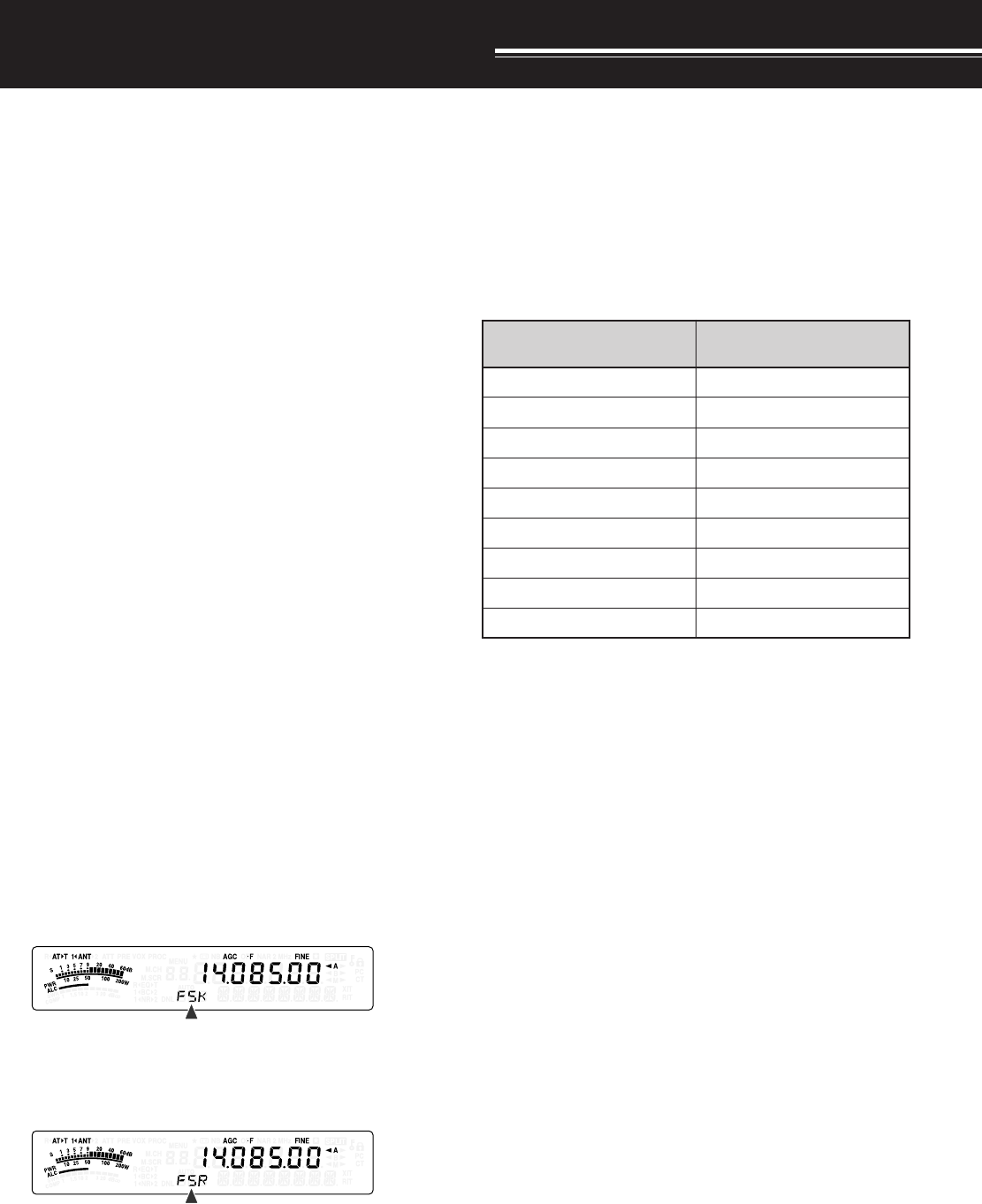
42
SPECIALIZED COMMUNICATIONS
RADIO TELETYPE (RTTY)
RTTY is the data communications mode with the
longest history. It was originally designed for use with
mechanical teletypewriters which were often used
before personal computers became common. Now
you can easily start operating RTTY with a personal
computer and MCP. Unlike Packet, each time you
type a letter, it is transmitted over the air. What you
typed is transmitted and displayed on the computer
screen of the recipient.
RTTY operation uses frequency shift keying (FSK)
and the 5-bit Baudot code or the 7-bit ASCII code to
transmit information.
For the cable connections, refer to “RTTY
OPERATION” {page 80}.
For further information, consult reference books
about Amateur Radio.
1Access Menu No. 41 and select an FSK shift.
• FSK shift is the difference in frequencies
between a mark and a space.
• The 170 Hz shift (default) is normally used on
the Amateur bands for the RTTY.
2Access Menu No. 42 and select a key-down
polarity.
• Select “oFF” (default) to transmit a mark when
keying down or “on” to transmit a space.
3Access Menu No. 43 and select high tone
(2125 Hz) or low tone (1275 Hz) for mark.
• High tone (default) is commonly used
nowadays.
4Select an operating frequency.
5Press [MODE] to select FSK mode {page 19}.
• If necessary, use Menu No. 47 to configure the
appropriate audio level from your MCP.
The AF control cannot be used to adjust the
audio level from your MCP.
6Some stations may be operating in Reverse shift.
In this case, press [MODE] (1 s) to reverse the
shift (the upper sideband is used).
• “FSR” appears.
• Traditionally, the lower sideband is used for
FSK operation. Press [MODE] (1 s) again to
return to the lower sideband. “FSK” appears.
7Follow the instructions provided with your MCP
and enter a command from your computer to
transmit.
• The LED changes from green (RX) to red (TX).
8Begin sending data from your computer.
• Press [PWR/ 4/ TX MONI] (1 s) to monitor your
signals. Press [PWR/ 4/ TX MONI] (1 s) again
to quit this function.
9When finished transmitting, enter a command from
your computer to return to reception mode.
• The LED changes from red (TX) to green (RX).
The following frequencies (measured in kHz)
commonly used for RTTY operation:
adanaC/.A.S.U 1noigeRURA )acirfA/eporuE(
0481~00812481~8381
)0953:XD(5463~50630263~0853
)0407:XD(0017~08075407~5307
05101~0410105101~04101
5.99041~070415.99041~08041
01181~0018190181~10181
00112~0701202112~08012
03942~0294292942~02922
05182~0708205182~05082
43
9 SPECIALIZED COMMUNICATIONS
AMTOR/ PacTOR/ CLOVER/ G-TOR/ PSK31
Besides RTTY, digital modes which have been used
among hams include AMTOR, PacTOR, CLOVER, G-
TOR, and PSK31. For details, consult reference
books about the digital mode communications of
amateur radio.
AMTOR (AMateur Teleprinting Over Radio) has
brought amateur HF digital communication into the
computer age. It is the first error-free HF digital mode
by which data bursts (not steady stream of data) are
transmitted.
PacTOR (Packet Teleprinting On Radio) has
combined the best features of both AMTOR and
Packet to improve the efficiency of HF digital
communications. Like Packet and AMTOR, PacTOR
sends error-free data using a handshaking method.
Of all the Amateur Radio HF digital modes, CLOVER
offers the best overall performance using a
complicated modulation technique, automatic power
adjustment and other advanced features. It may
allow communications to be maintained under the
worst conditions.
G-TOR (Golay-coded Teleprinting Over Radio) is a
relatively new Amateur Radio digital mode currently in
use. G-TOR was developed specifically to handle the
adverse conditions of communicating across the solar
system with spacecraft during their missions.
PSK31 was developed by an RTTY enthusiast,
G3PLX, in the United Kingdom. The operating
technique is very similar to the conventional Baudot-
RTTY, although more sensitive fine-tuning is required,
as a PSK31 signal requires a tuning accuracy of a
few Hertz. A special feature of PSK31 is that it allows
the entire ASCII character set, including the back
space character.
Your MCP should handle some or all of the above
modes. For available modes on your MCP, consult
the instruction manual for the MCP. For the cable
connections, refer to “MCP AND TNC” {page 81}.
On most HF bands, audio frequency shift keying
(AFSK) is used for the above modes. This method of
modulation uses audio tones, therefore either LSB or
USB mode should be selected. Traditionally, LSB is
used, similar to RTTY, with the exception of AMTOR
which is normally operated in USB.
AMTOR activity can be found on or near 14075 kHz
and 3637.5 kHz. These are also good starting places
when searching for PacTOR, CLOVER, G-TOR, or
PSK31 stations.
The TS-480 transceiver has special DSP filters for
these digital modes. Refer to page 48 for details.
Note:
When using SSB mode for digital operation, use a fast AGC
setting and switch your Speech Processor OFF.
PACKET RADIO
Packet is a unit of data transmitted as a whole from
one computer to another, on a network. Packets can
be transmitted on radio waves as well as on
communications lines. Besides a transceiver and a
computer, all you need is a terminal node controller
(TNC) or Multimode Communications Processor
(MCP). One of the tasks of TNCs and MCPs is to
convert data packets to audio tones, and vice versa.
Connecting a TNC to this transceiver allows you to
use many packet applications.
A variety of packet applications developed by hams
include packet bulletin board systems (PBBSs).
PBBSs are created and maintained by volunteers
called System Operators (SysOp). You may access
one of your local PBBSs to send e-mail, download
files, or obtain various useful information. Thousands
of PBBSs, which have formed a worldwide network,
relay e-mail to their intended destinations around the
world.
When you access a local PBBS for the first time, you
often need to register as a new user. After you are
successfully registered, it will then be available as
your home PBBS. E-mail addressed to you will be
held under a directory, called a mailbox, on your
home PBBS.
For further information, consult reference books
which should be available at any store that handles
Amateur Radio equipment. Web pages relating to
Packet will also be helpful. On Internet search
engines, use “Packet Radio” as key words to find
those Web pages.
Note:
◆
Unlike a TNC, a Multimode Communications Processor (MCP)
serves as a communications interface in several digital modes
such as Packet, RTTY, and AMTOR. You can cause it to switch
among the modes by sending a single command from your
computer.
◆
If there is an amateur radio club in your area, consider becoming
a member. You can often learn more in an hour from
experienced hobbyists, than in a month of independent research.
Ask on the local repeaters or contact your national amateur radio
organization (the ARRL in the U.S.A.) for information on local
amateur radio clubs. You’ll be glad you did.
PBBS