JVC KENWOOD 33101110 HF Transceiver with Scanning Receiver User Manual 0 Front page
JVC KENWOOD Corporation HF Transceiver with Scanning Receiver 0 Front page
UserManual.wiki
>
JVC KENWOOD
>
33101110 User Manual
>
Users Manual 1
Contents
1.
Users Manual 1
2.
Users Manual 2
Users Manual 1
Navigation menu
Upload a User Manual
Namespaces
Wiki Guide
HTML
PDF
Info
Views
User Manual
Discussion / Help
Navigation
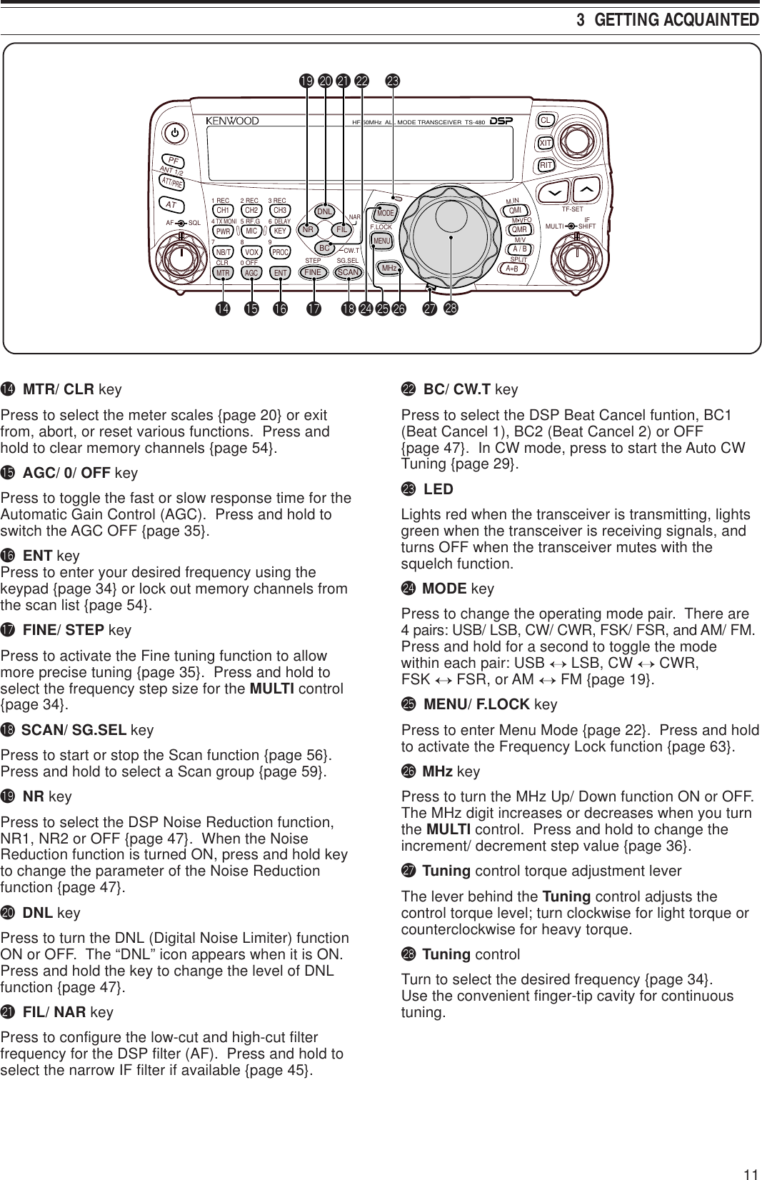
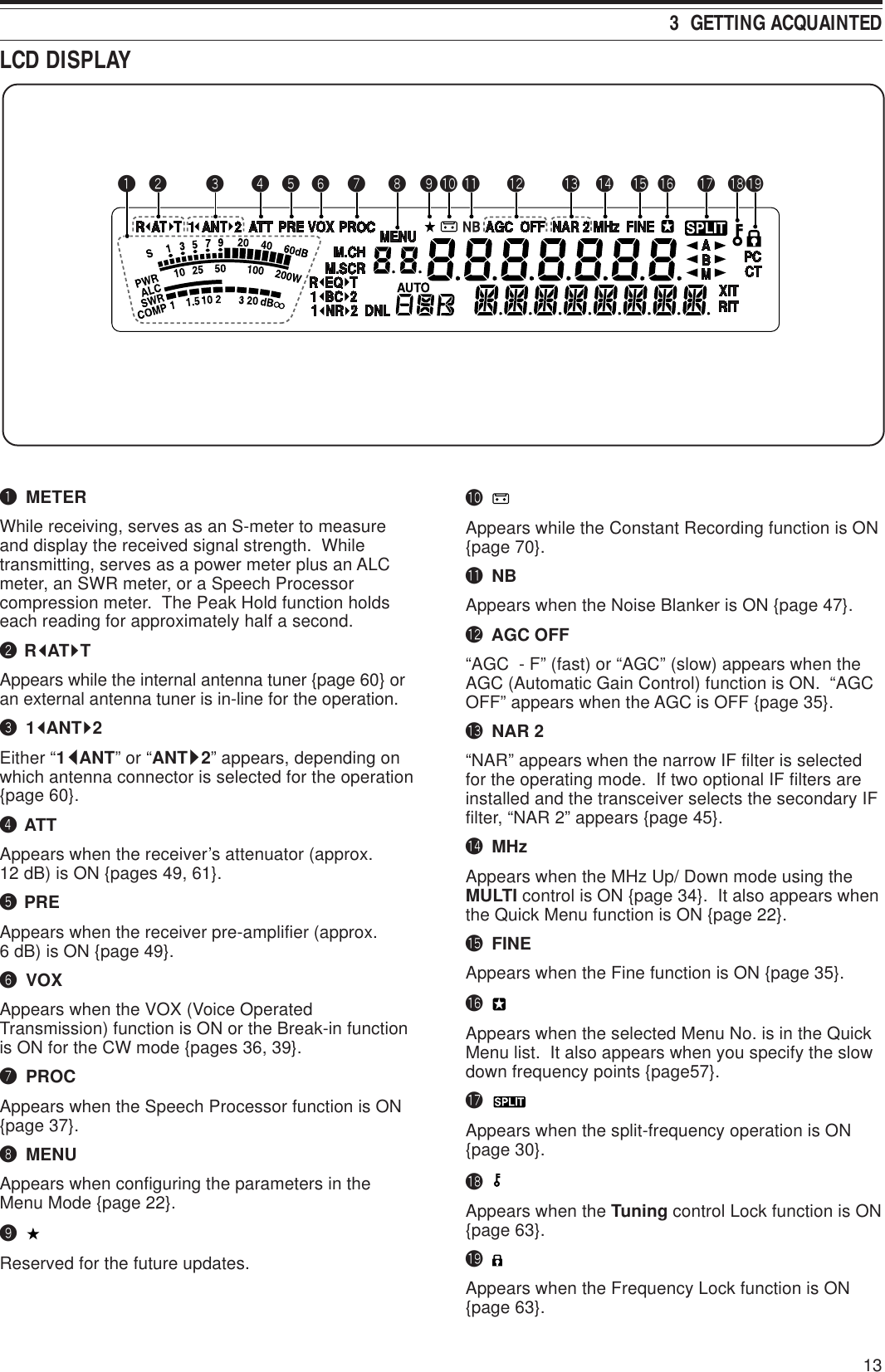
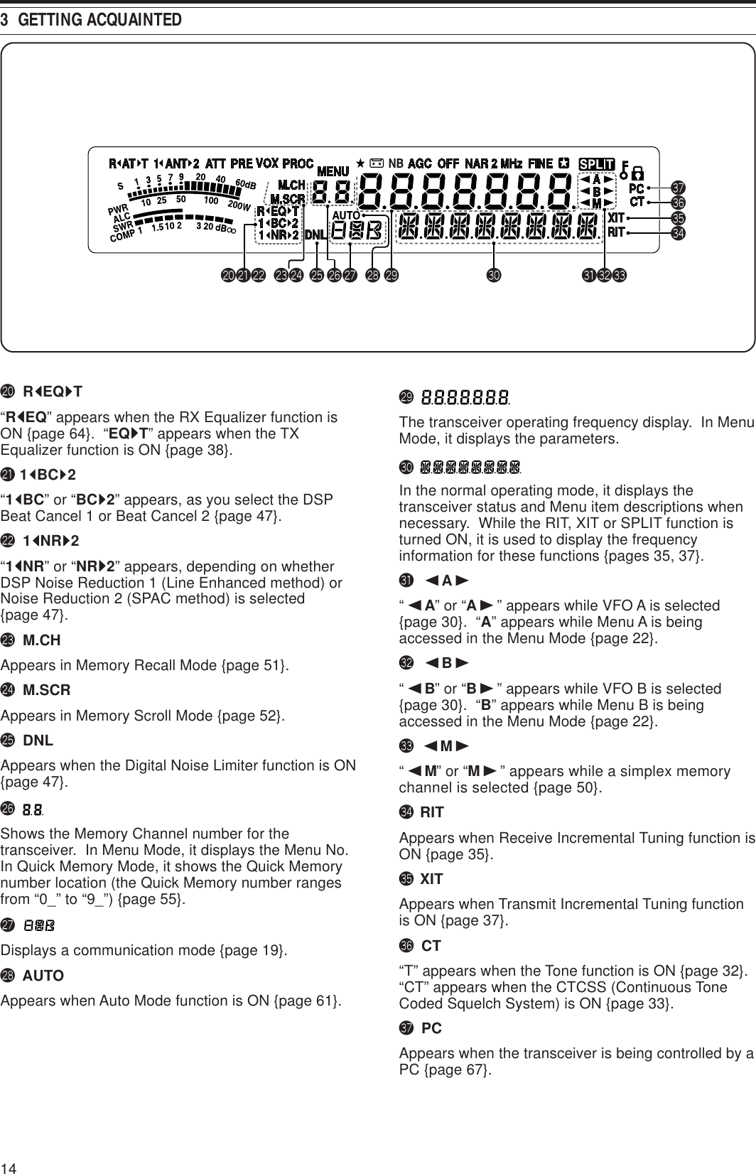
![iiTHANK YOUMODELS COVERED BY THIS MANUALThe models listed below are covered by this manual.TS-480SAT: HF/ 50 MHz All mode Transceiver withAutomatic Antenna Tuner (100 wattsoutput)TS-480HX : HF/ 50 MHz All mode Transceiver(200 watts output)MARKET CODESK-type : The AmericasE-type : Europe/ GeneralThe market code is shown on the carton box.Refer to the specifications {page 92} for informationon the available operating frequencies.WRITING CONVENTIONS FOLLOWEDThe writing conventions described below have beenfollowed to simplify instructions and avoidunnecessary repetition.noitcurtsnI oDottahWsserP ]YEK[ .esaelerdnasserP YEK .sserP ]1YEK[ ,]2YEK[ .sserP 1YEK esaeler,yliratnemom1YEK sserpneht, 2YEK .sserP ]YEK[)s1( .dlohdnasserP YEK arofnwod esaelernehtdnadnoces YEK .sserP ]2YEK[+]1YEK[ .dlohdnasserP 1YEK neht,nwodsserp 2YEK eromeraerehtfI. dlohdnasserp,syekowtnaht ehtlitnunrutniyekhcaenwod .desserpneebsahyeklanifsserP ][+]YEK[ .sserp,FFOreviecsnartehthtiW dlohdna YEK NOhctiwsneht, gnisserpybrewopreviecsnarteht ][ .)REWOP(](https://usermanual.wiki/JVC-KENWOOD/33101110.Users-Manual-1/User-Guide-366710-Page-4.png)
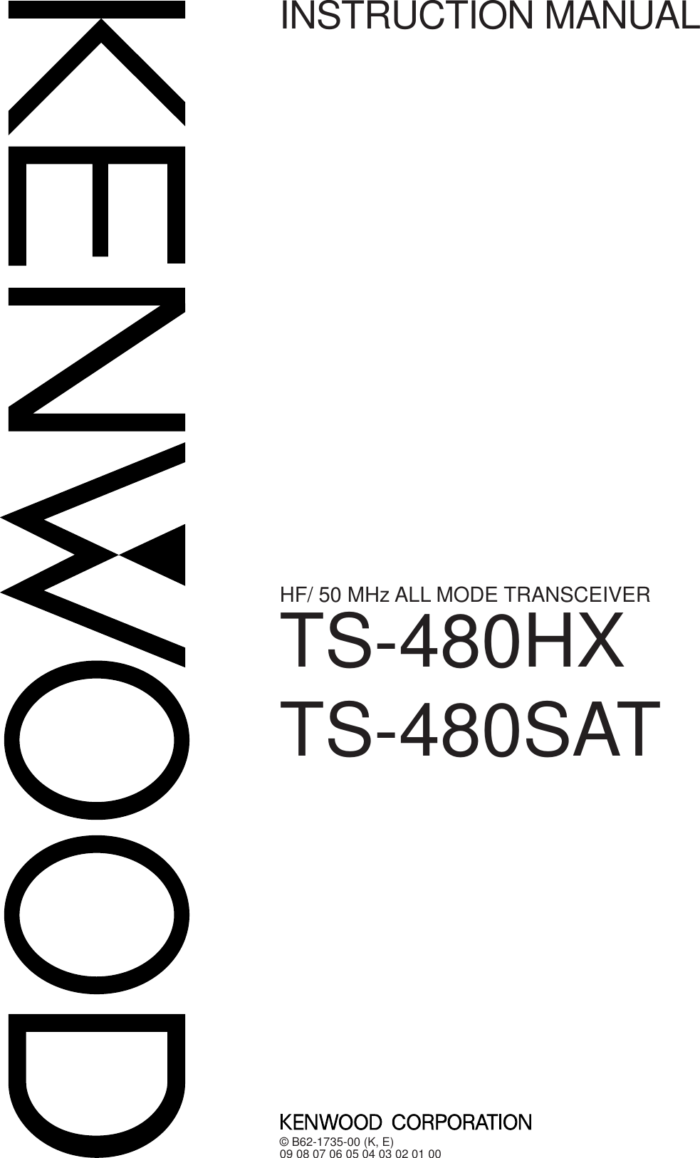
![8YOUR FIRST QSOAre you ready to give your TS-480SAT/ HX a quicktry? Reading these two pages should get your voiceon the air in your first QSO on the HF/ 50 MHz bandshortly. The instructions below are intended only fora quick guide. If you encounter problems or there issomething you don’t understand, read the detailedexplanations given later in this manual.Note: This section explains only keys and controls required tobriefly try the transceiver.qSet the following as specified:•AF control: Fully counterclockwise•SQL control: Fully counterclockwiseThen, switch ON the DC power supply if you areusing the DC power supply. If you are operating thetransceiver with the car batteries, ensure that the DCpower source(s) are available at the DC connector(s).wPress and hold [ ] (POWER) briefly to turn ONthe transceiver.• Do not press the switch for more thanapproximately 2 seconds; the transceiver willbe switched OFF.• Upon power up, “HELLO” appears, followed bythe selected frequency and other indicators.deConfirm that VFO A has been selected forcommunications; “tA” should be visible on thedisplay. If it has not, press [A/B / M/V] to selectVFO A.rTurn the AF control slowly clockwise until you heara suitable level of background noise.tPress [ ]/ [ ] to select a desired HF/ 50 MHzAmateur radio band.yPress [MODE] to select the desiredcommunication mode.• There are 4 mode pairs: USB/ LSB, CW/ CWR(Reversed pitch), FSK/ FSR (Reverse shift)and AM/ FM. Press [MODE] (1 s) to toggle themode within each pair: USB LSB,CW CWR, FSK FSR, or AM FM.• To select the alternate mode on each operatingmode, press and hold the key for 1 second.For example, if USB is selected, press[MODE] (1 s) to switch to LSB mode. Thefollowing diagram illustrates how to accesseach mode.MODEMODEMODEMODEMODE(1 s)MODE(1 s)MODE(1 s)MODE(1 s)uIf you have selected FM, turn the SQL controlclockwise until the background noise is justeliminated; the green LED (above the [MODE]key) turns OFF.• With LSB or USB selected, skip this step.iTurn the Tuning control to tune in a station.• If you do not hear any stations, you may havethe wrong antenna connector selected. In thiscase, try selecting another antenna by pressingand hold [ATT/PRE/ ANT1/2] (1 s).NAR1 REC 2 REC5 RF.G0 OFF83 REC947TX MONI6DELAYHF/50MHz ALL MODE TRANSCEIVER TS-480CLR STEP SG.SELCW.TF.LOCKM/VSPLITM VFOM.INTF-SETMULTI IFSHIFTAF SQLPFATCH1 CH2 CH3PWR MIC KEYVOXPROCAGCENTA / BA=BMODEMHzQMIQMRMENUMTRNB/TANT 1/2FINE SCANDNLBCNR FILRITXITCLATT/PREeirquqrywtRECEPTION](https://usermanual.wiki/JVC-KENWOOD/33101110.Users-Manual-1/User-Guide-366710-Page-13.png)
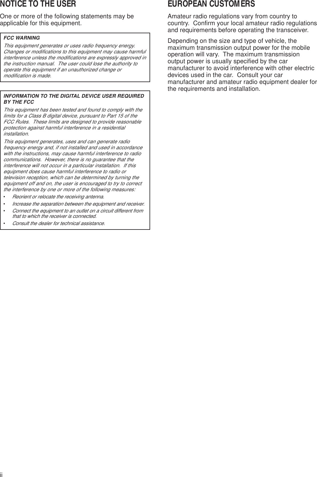
![92 YOUR FIRST QSOqTurn the Tuning control to tune in a desiredstation or to select an unused frequency.• If you are operating the TS-480HX transceiverwithout the AT-300 antenna tuner, continue tostep 4.wPress [AT] momentarily.•“RtATsT” appears.ePress and hold [AT] to start tuning the antennatuner (TS-480SAT or TS-480HX with the AT-300antenna tuner).•“RtATsT” starts blinking and the LED abovethe [MODE] key turns red.• Tuning should be completed in under20 seconds, then a morse code “T” (a longsingle beep) sounds and “ATsT” stops blinking.• If tuning is not completed within 20 seconds,error beeps sound. Press [AT] to stop theerror beeps and quit tuning. Check yourantenna system before continuing. If you donot press [AT], tuning will continue forapproximately 60 seconds.Note: You will hear a lot of clicking sounds coming from thetransceiver or external antenna tuner while the antenna tuner istrying to tune the antenna. This is simply the relay switchesturning ON and OFF.rWith LSB, USB, or AM selected, press[MIC/ 5/ RF.G] to adjust the Microphone Gain.• “MIC -- 50” appears.• With FM selected, skip this step.tPress Mic [PTT].• The LED lights red.yBegin speaking into the microphone in yournormal tone of voice.uLSB/ USB: While speaking into the microphone,adjust the MULTI control so that the ALC meterreflects according to your voice level.AM: While speaking into the microphone, adjustthe MULTI control so that the power meter slightlyreflects to your voice level.FM: Skip this step.iWhen you finish speaking, release Mic [PTT] toreturn to receive mode.oPress [MIC/ 5/ RF.G] to finish adjusting theMicrophone Gain.Note: If desired, access Menu No. 44 {page 27} to adjust theMicrophone Gain for FM mode.This completes your introduction to the TS-480transceiver, but there is a great deal more to know.“OPERATING BASICS” {page 18} and the followingchapters explain all the functions of this transceiver,starting with the most basic, commonly-usedfunctions.NAR1 REC 2 REC5 RF.G0 OFF83 REC947TX MONI6DELAYHF/50MHz ALL MODE TRANSCEIVER TS-480CLR STEP SG.SELCW.TF.LOCKM/VSPLITM VFOM.INTF-SETMULTI IFSHIFTAF SQLPFATCH1 CH2 CH3PWR MIC KEYVOXPROCAGCENTA / BA=BMODEMHzQMIQMRMENUMTRNB/TANT 1/2FINE SCANDNLBCNR FILRITXITCLATT/PREqwetiro tuTRANSMISSION](https://usermanual.wiki/JVC-KENWOOD/33101110.Users-Manual-1/User-Guide-366710-Page-14.png)
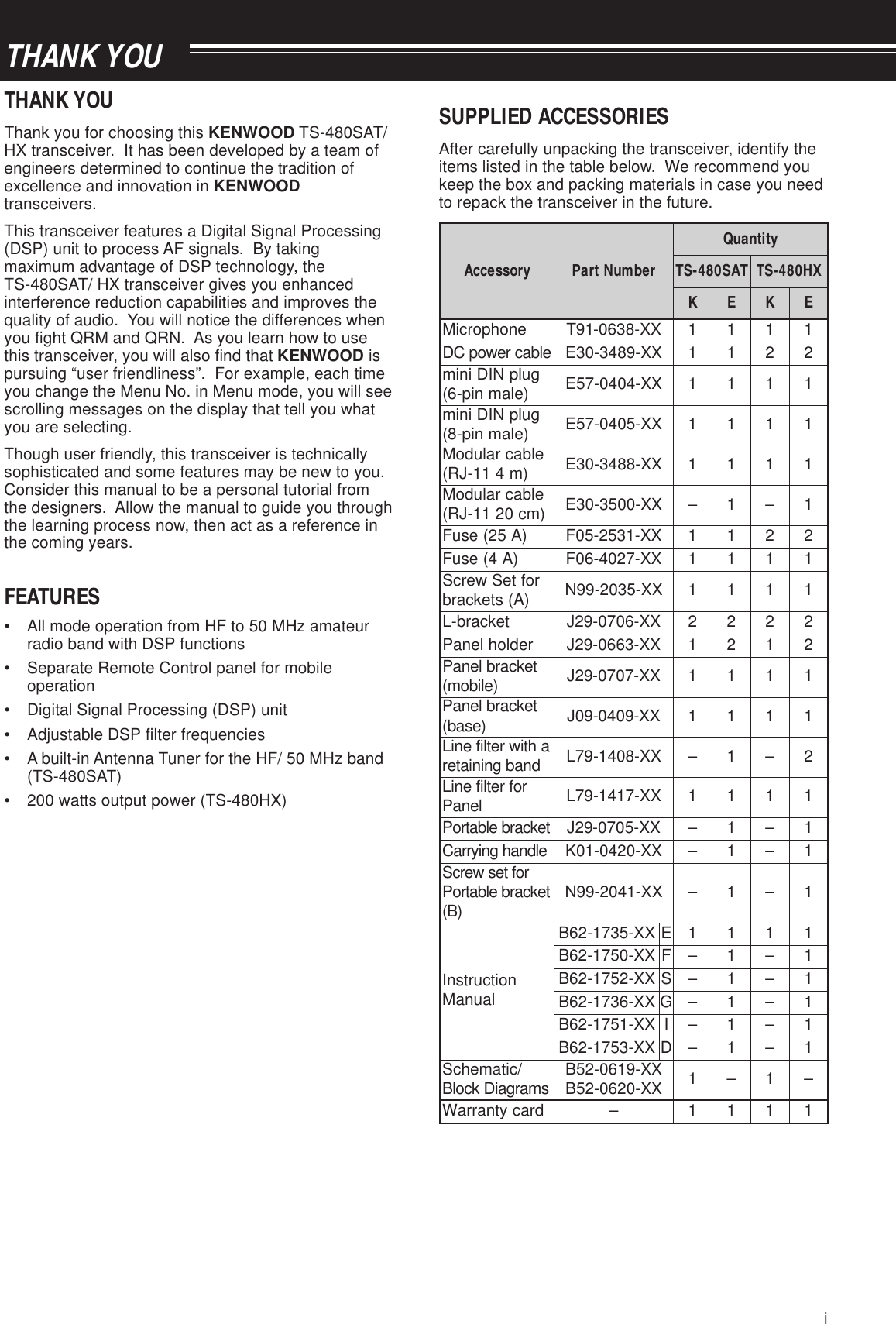
![10GETTING ACQUAINTEDREMOTE CONTROL PANELo MIC/ 5/ RF.G keyPress to adjust the microphone gain {page 27}.While the Speech Processor function is ON, press toadjust the Speech Processor output level {page 37}.Press and hold to adjust the receiver RF gain{page 18}.!0 KEY/ 6/ DELAY keyPress to adjust the internal electronic keyer speed.Press and hold to adjust the VOX delay time {page36} or break-in time (Full break-in/ Semi break-intime) for CW mode {page 39}.!1 NB/T/ 7 keyPress to switch the Noise Blanker ON or OFF. Pressand hold to adjust the Noise Blanker level {page 47}.In FM mode, press to turn the Tone function ON orOFF {page 32}. Press and hold to select a sub-audibletone for the Tone funtion {page 32}.!2 VOX/ 8 keyIn Voice Mode, press to turn the VOX (Voice-Operated Transmit) function ON or OFF {page 36}.In CW mode, press to turn the Break-in function ONor OFF {page 39}. Press and hold to adjust themicrophone input gain for VOX operation. The VOXicon appears when the VOX (Voice)/ Break-in (CW)function is active.!3 PROC/ 9 keyPress to turn the Speech Processor ON or OFF{page 37}. Press and hold to adjust the SpeechProcessor input level. The PROC icon appears whenthe Speech Processor function is ON.q [ ] (POWER) switchPress and hold briefly to switch the transceiver powerON. Press again to switch the power OFF {page 18}.w PF keyYou can assign a function to this ProgrammableFunction key. The default function is VOICE1{page 64}.e ATT/PRE/ ANT 1/2 keyPress to cycle between receiver attenuator ON, pre-amplifier ON and OFF {pages 49, 61}.Press and hold for 1 second, then release it to toselect either ANT 1 or ANT 2 {page 60}.r ATPress to activate the internal antenna tuner {page 60}or an external antenna tuner. Press and hold to starttuning the automatic antenna tuner.t SQL controlUsed for muting (“squelching”) the speaker, the headphones and the AF output on DATA (8-pin mini DINconnector) when no receive signal is present on thetransceiver {page 19}.y AF controlTurn to adjust the audio volume on the transceiver{page 18}.u CH1/ 1/ REC, CH2/ 1/ REC, CH3/ 3/ REC keyPress to play back the CW or voice messages (theVGS-1 is required) {page 40}. Press and hold torecord the voice messages (the VGS-1 is required){page 68} or CW messages that are associated withthe internal electronic keyer {page 40}.i PWR/ 4/ TX MONI keyPress to adjust the transmission output power. Pressand hold to adjust the volume of the transmissionsignal monitor function {page 65}.NAR1 REC 2 REC5 RF.G0 OFF83 REC947TX MONI6DELAYHF/50MHz ALL MODE TRANSCEIVER TS-480CLR STEP SG.SELCW.TF.LOCKM/VSPLITM VFOM.INTF-SETMULTI IFSHIFTAF SQLPFATCH1 CH2 CH3PWR MIC KEYVOXPROCAGCENTA / BA=BMODEMHzQMIQMRMENUMTRNB/TANT 1/2FINE SCANDNLBCNR FILRITXITCLATT/PREwertyq !0u!1 !3!2io](https://usermanual.wiki/JVC-KENWOOD/33101110.Users-Manual-1/User-Guide-366710-Page-15.png)
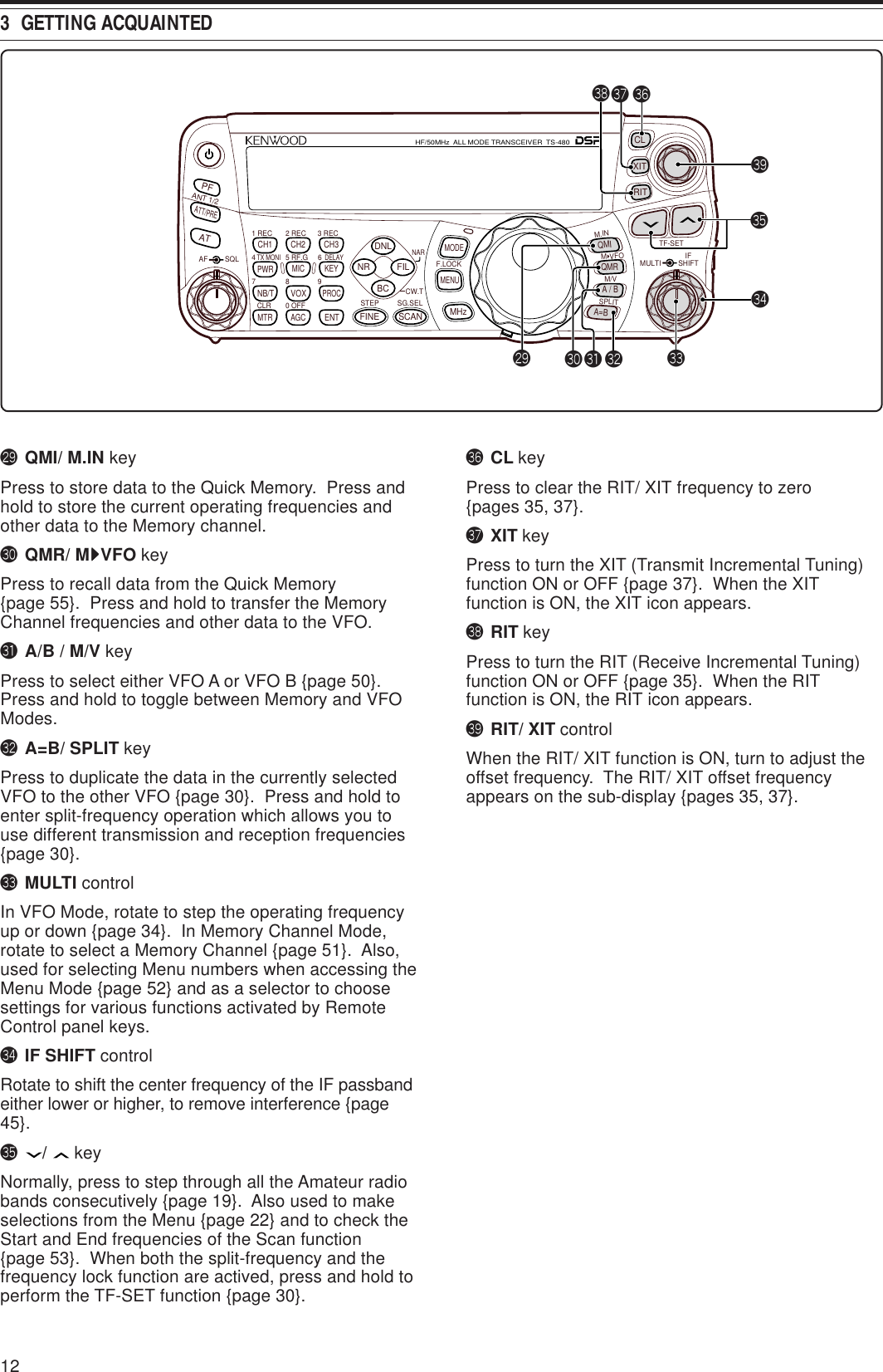
![18OPERATING BASICSSWITCHING POWER ON/ OFF1Switch the DC power supply(s) ON if you areusing a DC power supply(s).2Press and hold [ ] (POWER) briefly to switchthe transceiver ON.NAR1 REC 2 REC5 RF.G0 OFF83 REC947TX MONI6DELAYHF/50MHz ALL MODE TRANSCEIVER TS-480CLR STEP SG.SELCW.TF.LOCKM/VSPLITM VFOM.INTF-SETMULTI IFSHIFTAF SQLPFATCH1 CH2 CH3PWR MIC KEYVOXPROCAGCENTA / BA=BMODEMHzQMIQMRMENUMTRNB/TANT 1/2FINE SCANDNLBCNR FILRITXITCLATT/PRE• Do not press the switch for more thanapproximately 2 seconds; the transceiver willbe switched OFF.•TS-480HX only: If “RX ONLY” appears on thesub-display upon power up, confirm that twoDC cable connectors are securely connected tothe DC-1 and DC-2 connectors. When thiswarning message appears, you can receivesignals as usual but you cannot transmit even ifyou decrease the output power. “TWIN PWR”appears when two DC power cables areconnected to the DC-1 and DC-2 connectors.• Upon power up, “HELLO” appears on the maindisplay, followed by the selected frequency andother indicators.3To switch the transceiver OFF, press [ ](POWER) again.4Switch the DC power supply(s) OFF.• You may skip step 3. After switching thetransceiver ON, you can switch it OFF or ONusing only the power switch of the DC powersupply(s). The transceiver remembers theinformation of the POWER switch positionwhen the DC power source is switched OFF.ADJUSTING VOLUMEAF (AUDIO FREQUENCY) GAINTurn the AF control clockwise to increase the audiolevel and counterclockwise to decrease the level.NAR1 REC 2 REC5 RF.G0 OFF83 REC947TX MONI6DELAYHF/50MHz ALL MODE TRANSCEIVER TS-480CLR STEP SG.SELCW.TF.LOCKM/VSPLITM VFOM.INTF-SETMULTI IFSHIFTAF SQLPFATCH1 CH2 CH3PWR MIC KEYVOXPROCAGCENTA / BA=BMODEMHzQMIQMRMENUMTRNB/TANT 1/2FINE SCANDNLBCNR FILRITXITCLATT/PREAF SQLNote: The position of the AF control does not affect the volume ofbeeps caused by pressing keys nor the CW TX sidetone. The audiolevel for Digital mode operation is also independent of the AF controlsetting.RF (RADIO FREQUENCY) GAINThe RF GAIN is normally configured to the maximumlevel regardless of the operating modes. Thetransceiver has been configured to the maximumlevel at the factory. However, you may decrease theRF GAIN slightly when you have trouble hearing thedesired signal because of excessive atmosphericnoise or interference from other stations. First, takenote of the peak S-meter reading of the desiredsignal.1Press [MIC/ RF.G] (1 s).NAR1 REC 2 REC5 RF.G0 OFF83 REC947TX MONI6DELAYHF/50MHz ALL MODE TRANSCEIVER TS-480CLR STEP SG.SELCW.TF.LOCKM/VSPLITM VFOM.INTF-SETMULTI IFSHIFTAF SQLPFATCH1 CH2 CH3PWR MIC KEYVOXPROCAGCENTA / BA=BMODEMHzQMIQMRMENUMTRNB/TANT 1/2FINE SCANDNLBCNR FILRITXITCLATT/PRE• The current RF GAIN level appears on thesub-display (0: minimum ~ 100: maximum).2Turn the MULTI control counterclockwise until theS-meter reads the peak value that you noted.NAR1 REC 2 REC5 RF.G0 OFF83 REC947TX MONI6DELAYHF/50MHz ALL MODE TRANSCEIVER TS-480CLR STEP SG.SELCW.TF.LOCKM/VSPLITM VFOM.INTF-SETMULTI IFSHIFTAF SQLPFATCH1 CH2 CH3PWR MIC KEYVOXPROCAGCENTA / BA=BMODEMHzQMIQMRMENUMTRNB/TANT 1/2FINE SCANDNLBCNR FILRITXITCLATT/PRE• Signals that are weaker than this level will beattenuated and reception of the station willbecome easier.Depending on the type and gain of your antenna, andthe condition of the band, adjust the RF GAIN. Whenusing FM Mode, always adjust the RF GAIN to themaximum level.SELECTING VFO A OR VFO B2 VFOs are available for controlling the frequency onthe transceiver. Each VFO (VFO A and VFO B)works independently so that a different frequency andmode can be selected. For example, when SPLIToperation is activated, VFO A is used for receptionand VFO B is used for transmission. The oppositecombination is also possible.Press [A/B / M/V] to toggle between VFO A and B.NAR1 REC 2 REC5 RF.G0 OFF83 REC947TX MONI6DELAYHF/50MHz ALL MODE TRANSCEIVER TS-480CLR STEP SG.SELCW.TF.LOCKM/VSPLITM VFOM.INTF-SETMULTI IFSHIFTAF SQLPFATCH1 CH2 CH3PWR MIC KEYVOXPROCAGCENTA / BA=BMODEMHzQMIQMRMENUMTRNB/TANT 1/2FINE SCANDNLBCNR FILRITXITCLATT/PRE•“tA” or “tB” appears to indicate which VFO isselected.](https://usermanual.wiki/JVC-KENWOOD/33101110.Users-Manual-1/User-Guide-366710-Page-23.png)
![194 OPERATING BASICSSELECTING A BANDPress [ ]/ [ ] to select your desired band.• Holding down either key changes the bandscontinuously.NAR1 REC 2 REC5 RF.G0 OFF83 REC947TX MONI6DELAYHF/50MHz ALL MODE TRANSCEIVER TS-480CLR STEP SG.SELCW.TF.LOCKM/VSPLITM VFOM.INTF-SETMULTI IFSHIFTAF SQLPFATCH1 CH2 CH3PWR MIC KEYVOXPROCAGCENTA / BA=BMODEMHzQMIQMRMENUMTRNB/TANT 1/2FINE SCANDNLBCNR FILRITXITCLATT/PRESELECTING A MODEPress [MODE] to cycle through the 4 mode pairs:USB/ LSB, CW/ CWR, FSK/ FSR, and AM/ FM. Eachtime you press [MODE], the mode display cyclesUSB or LSB, CW or CWR, FSK or FSR, FM or AM.To select the other mode on each pair, press [MODE](1 s). For example, to select “LSB” while “USB” isvisible, press [MODE] (1 s). “USB” changes to“LSB”. Press [MODE] (1 s) again to go back to“LSB” from “USB”. The following illustrationdescribes how to access each mode with the [MODE]key.NAR1 REC 2 REC5 RF.G0 OFF83 REC947TX MONI6DELAYHF/50MHz ALL MODE TRANSCEIVER TS-480CLR STEP SG.SELCW.TF.LOCKM/VSPLITM VFOM.INTF-SETMULTI IFSHIFTAF SQLPFATCH1 CH2 CH3PWR MIC KEYVOXPROCAGCENTA / BA=BMODEMHzQMIQMRMENUMTRNB/TANT 1/2FINE SCANDNLBCNR FILRITXITCLATT/PREMODEMODEMODEMODEMODE(1 s)MODE(1 s)MODE(1 s)MODE(1 s)Access Menu No. 2 then press [ ] to select “on” toturn the Auto Mode selection ON. When it is ON,“AUTO” appears. As a default setting, if you changethe frequency above or below 9.5 MHz, thetransceiver automatically switches modes; LSB forfrequencies under 9.5 MHz and USB for frequenciesequal to or over 9.5 MHz. You can further add thefrequency table data to change the modeautomatically {page 61}.ADJUSTING SQUELCHThe purpose of the Squelch is to mute the speakerwhen no signals are present. With the squelch levelcorrectly set, you will hear sound only while actuallyreceiving signals. The higher the selected squelchlevel, the stronger the signals must be to receive.The appropriate squelch level depends on theambient RF noise conditions.Turn the SQL control when there are no signalspresent to select the squelch level at which thebackground noise is just eliminated; the green LEDwill turn off. Many ham operators prefer leaving theSQL control fully counterclockwise unless operatingon a full-carrier mode such as FM. The squelchlevel for the main transceiver is preset at the factoryto approximately the 9 o’clock position for FM and 11o’clock for SSB and AM.NAR1 REC 2 REC5 RF.G0 OFF83 REC947TX MONI6DELAYHF/50MHz ALL MODE TRANSCEIVER TS-480CLR STEP SG.SELCW.TF.LOCKM/VSPLITM VFOM.INTF-SETMULTI IFSHIFTAF SQLPFATCH1 CH2 CH3PWR MIC KEYVOXPROCAGCENTA / BA=BMODEMHzQMIQMRMENUMTRNB/TANT 1/2FINE SCANDNLBCNR FILRITXITCLATT/PRESELECTING A FREQUENCYTurn the Tuning control clockwise or press Mic [UP]to increase the frequency. Turn the Tuning controlcounterclockwise or press Mic [DWN] to decrease thefrequency.NAR1 REC 2 REC5 RF.G0 OFF83 REC947TX MONI6DELAYHF/50MHz ALL MODE TRANSCEIVER TS-480CLR STEP SG.SELCW.TF.LOCKM/VSPLITM VFOM.INTF-SETMULTI IFSHIFTAF SQLPFATCH1 CH2 CH3PWR MIC KEYVOXPROCAGCENTA / BA=BMODEMHzQMIQMRMENUMTRNB/TANT 1/2FINE SCANDNLBCNR FILRITXITCLATT/PREYou may prefer directly entering a frequency usingthe numeric keypad if the desired frequency is farfrom the current frequency. Press [ENT], then pressthe numeric keys as necessary. For details, refer to“Direct Frequency Entry” {page 34}.1CH1/REC2CH2/REC3CH3/REC4TONE/SEL5METER6CTCSS/SEL7NB/LEVEL8AGC/OFF9FINE/STEP.DCS/SEL0SHIFT/OFFSETENTPFF LOCK A1CH1/REC2CH2/REC3CH3/REC4TONE/SEL5METER6CTCSS/SEL7NB/LEVEL8AGC/OFF9FINE/STEP.DCS/SEL0SHIFT/OFFSETENTSENDPHONESMICATANT1/2PROCLEVELVOXATT PRELEVELLEVELLEVELMANUALLO/WIDTHHI/SHIFTN.R.A.N.B.C.FUNCCLRMAINAUTOCARTX MONIDELAY NARREVMICPWRKEYLSBUSBCWFSKFM AMDISPSEL1MHz CTRLMENMHF/VHE/UHF ALL MOThis transceiver provides many other methods forquickly selecting a frequency. For further information,refer to “SELECTING YOUR FREQUENCY”{page 34}.](https://usermanual.wiki/JVC-KENWOOD/33101110.Users-Manual-1/User-Guide-366710-Page-24.png)
![4 OPERATING BASICS20FRONT PANEL METERThe multi-function meter measures the parameters inthe table below. The S-meter scale appears whenthe transceiver is in reception mode, and the PWRmeter appears when it is in transmission mode.Each time you press [MTR/ CLR], it cycles betweenthe ALC, SWR, and COMP meters. Peak readingsfor the S-meter, ALC, SWR, COMP, and PWRfunctions are held momentarily.NAR1 REC 2 REC5 RF.G0 OFF83 REC947TX MONI6DELAYHF/50MHz ALL MODE TRANSCEIVER TS-480CLR STEP SG.SELCW.TF.LOCKM/VSPLITM VFOM.INTF-SETMULTI IFSHIFTAF SQLPFATCH1 CH2 CH3PWR MIC KEYVOXPROCAGCENTA / BA=BMODEMHzQMIQMRMENUMTRNB/TANT 1/2FINE SCANDNLBCNR FILRITXITCLATT/PRE Multi-function meterreteM ?derusaeMsItahWSslangisdeviecerfohtgnertSRWP rewoptuptuonoissimsnarTCLA sutatslortnoclevelcitamotuARWS oitarevawgnidnatsmetsysannetnAPMOC gnisunehwlevelnoisserpmochceepS }73egap{rossecorPhceepSehtNote:◆The COMP meter functions only when the Speech Processor isON for SSB, FM, or AM mode.◆Peak Hold readings cannot be deactivated.TRANSMITTINGFor voice communications, press and hold Mic [PTT],then speak into the microphone in your normal toneof voice. When you finish speaking, release Mic[PTT] to receive.To transmit CW, press [VOX/ 8] to switch the Break-infunction ON. “VOX” appears. Close the key or keyerpaddle. Connect a key or keyer paddle {pages 7, 15},then select CW using [MODE] {page 19}.NAR1 REC 2 REC5 RF.G0 OFF83 REC947TX MONI6DELAYHF/50MHz ALL MODE TRANSCEIVER TS-480CLR STEP SG.SELCW.TF.LOCKM/VSPLITM VFOM.INTF-SETMULTI IFSHIFTAF SQLPFATCH1 CH2 CH3PWR MIC KEYVOXPROCAGCENTA / BA=BMODEMHzQMIQMRMENUMTRNB/TANT 1/2FINE SCANDNLBCNR FILRITXITCLATT/PREFor a detailed explanation on transmitting, refer to“BASIC COMMUNICATIONS”, beginning on page 27.SELECTING TRANSMISSION POWERIt is wise to select a lower transmission power ifcommunication is still reliable. This lowers the risk ofinterfering with others on the band. When operatingfrom battery power, selecting a lower transmissionpower allows you more operating time beforerecharging is necessary. This transceiver allows youto change the transmission power even whiletransmitting.1Press [PWR/ 4/ TX MONI].• The current transmission power appears.NAR1 REC 2 REC5 RF.G0 OFF83 REC947TX MONI6DELAYHF/50MHz ALL MODE TRANSCEIVER TS-480CLR STEP SG.SELCW.TF.LOCKM/VSPLITM VFOM.INTF-SETMULTI IFSHIFTAF SQLPFATCH1 CH2 CH3PWR MIC KEYVOXPROCAGCENTA / BA=BMODEMHzQMIQMRMENUMTRNB/TANT 1/2FINE SCANDNLBCNR FILRITXITCLATT/PRE42Turn the MULTI control counterclockwise toreduce the power or clockwise to increase thepower.NAR1 REC 2 REC5 RF.G0 OFF83 REC947TX MONI6DELAYHF/50MHz ALL MODE TRANSCEIVER TS-480CLR STEP SG.SELCW.TF.LOCKM/VSPLITM VFOM.INTF-SETMULTI IFSHIFTAF SQLPFATCH1 CH2 CH3PWR MIC KEYVOXPROCAGCENTA / BA=BMODEMHzQMIQMRMENUMTRNB/TANT 1/2FINE SCANDNLBCNR FILRITXITCLATT/PRE• The selectable range differs, depending on thetransceiver model, the current band, and themode.3Press [PWR/ 4/ TX MONI] to complete the setting.Note: You may access Menu No. 21, and select “on” to change thestep size from 5 W to 1 W {page 65}.](https://usermanual.wiki/JVC-KENWOOD/33101110.Users-Manual-1/User-Guide-366710-Page-25.png)
![4 OPERATING BASICS21MICROPHONE GAINThe microphone gain must be adjusted when SSBor AM mode is selected without using the speechprocessor {pages 27, 28}.1Press [MIC/ 5/ RF.G].• The current microphone gain level appears.The range is from 0 to 100 with a default of 50.NAR1 REC 2 REC5 RF.G0 OFF83 REC947TX MONI6DELAYHF/50MHz ALL MODE TRANSCEIVER TS-480CLR STEP SG.SELCW.TF.LOCKM/VSPLITM VFOM.INTF-SETMULTI IFSHIFTAF SQLPFATCH1 CH2 CH3PWR MIC KEYVOXPROCAGCENTA / BA=BMODEMHzQMIQMRMENUMTRNB/TANT 1/2FINE SCANDNLBCNR FILRITXITCLATT/PRE2Press and hold Mic [PTT].• The LED on the panel lights red.3SSB: While speaking into the microphone, adjustthe MULTI control so that the ALC meter reflectsyour voice level but does not exceed the ALC limit.AM: While speaking into the microphone, adjustthe MULTI control so that the power meter slightlyreflects your voice level.FM: Access Menu No. 44 and select “1” (Low), “2”(Medium), or “3” (High) for the microphone gain,if necessary {page 27}.NAR1 REC 2 REC5 RF.G0 OFF83 REC947TX MONI6DELAYHF/50MHz ALL MODE TRANSCEIVER TS-480CLR STEP SG.SELCW.TF.LOCKM/VSPLITM VFOM.INTF-SETMULTI IFSHIFTAF SQLPFATCH1 CH2 CH3PWR MIC KEYVOXPROCAGCENTA / BA=BMODEMHzQMIQMRMENUMTRNB/TANT 1/2FINE SCANDNLBCNR FILRITXITCLATT/PRE4Release Mic [PTT] to return to receive.• The LED lights green or turns off, dependingon the SQL control setting.Note: When using the optional MC-90 microphone with the MJ-88 inFM mode, select “3” (High) for the microphone gain. The microphonesensitivity is low in FM mode. This may cause insufficientmodulation. For other microphones, select either “1” (Low) or “2”(Medium).](https://usermanual.wiki/JVC-KENWOOD/33101110.Users-Manual-1/User-Guide-366710-Page-26.png)
![22MENU SETUPWHAT IS A MENU?Many functions on this transceiver are selected orconfigured via a software-controlled Menu, ratherthan through the physical controls of the transceiver.Once familiar with the Menu system, you willappreciate the versatility it offers. You can customizethe various timings, settings, and programmingfunctions on this transceiver to meet your needswithout using many controls and switches.MENU A/ MENU BThis transceiver has 2 menus: Menu A and Menu B.These menus contain identical functions and can beconfigured independently. The transceiver, therefore,allows you to switch between 2 differentenvironments quickly and easily. For example, youcan configure Menu A for DXing and contesting whileMenu B is for relaxed local ragchewing. By switchingfrom Menu A to Menu B, you can instantly change theMenu configuration and key assignment to suit yourcurrent operating style. Or, 2 operators may share asingle transceiver by dedicating one Menu to eachoperator. Both operators can always enjoy their ownconfiguration.MENU ACCESS1Press [MENU/ F.LOCK].• The Menu No. and setting appear on thedisplay, and the explanation of the menuappears on the sub-display.2Press [A/B / M/V] to select Menu A or Menu B.• “A” or “B” appears, indicating which Menu isselected.3Turn the MULTI control to select the desired MenuNo.• Each time you change the Menu No.,a different scrolling message appears on thesub-display, describing the Menu No.4Press []/ [ ], or Mic [UP]/ [DWN] to select aparameter.5Press [MENU/ F.LOCK] to exit Menu mode.QUICK MENUBecause the number of functions this transceiverprovides is extraordinary, there are numerous items ineach Menu. If you find accessing desired Menu Nos.to be too time consuming, use the Quick Menu tocreate your own customized, abbreviated Menu. Youcan then add those Menu Nos. which you frequentlyuse, to the Quick Menu. Copying Menu Nos. to theQuick Menu has no effect on the Menu.PROGRAMMING THE QUICK MENU1Press [MENU/ F.LOCK].2Turn the MULTI control to select the desired MenuNo.3Press [QMI/ M.IN].• An inverted star, “ ” appears, indicating thatthe Menu item has been added to the QuickMenu.• To remove the item from the Quick Menu,press [QMI/ M.IN] again. “ ” disappears.4Press [MENU/ F.LOCK] to exit Menu mode.USING THE QUICK MENU1Press [MENU/ F.LOCK].2Press [MHz].• “MHz” appears.3Turn the MULTI control to select the desired QuickMenu No.4Press [ ]/ [ ], or Mic [UP]/[DWN] to change thecurrent setting for the selected Menu No.• When the Menu is registered to the QuickMenu list, “ ” appears.5Press [MENU/ F.LOCK] to exit Quick Menu mode.Note: If the Quick Menu has not been programmed, turning theMULTI control in step 2 causes “CHECK” to be output in Morse code.](https://usermanual.wiki/JVC-KENWOOD/33101110.Users-Manual-1/User-Guide-366710-Page-27.png)
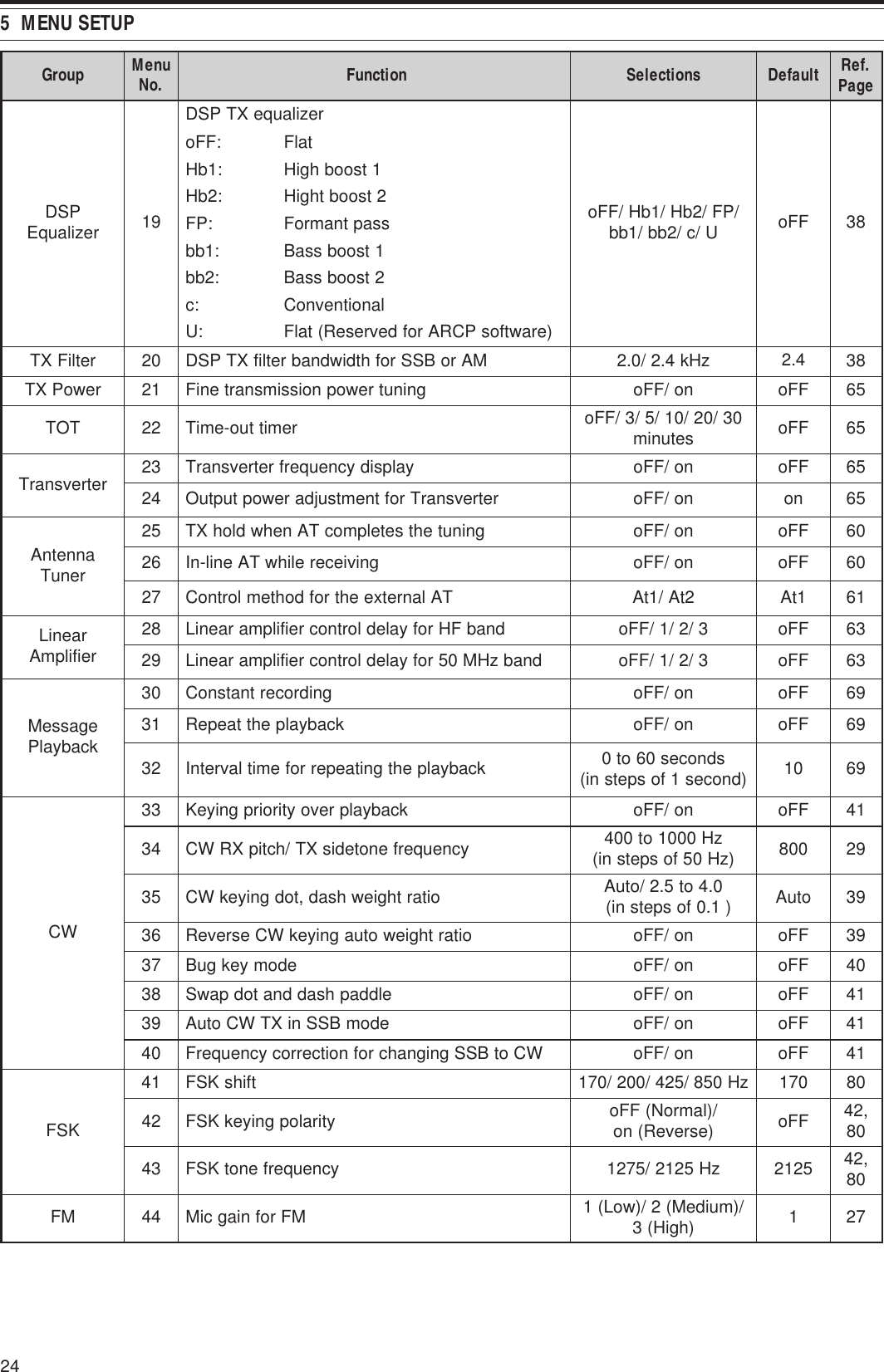
![27BASIC COMMUNICATIONSSSB TRANSMISSIONSSB is the most commonly-used mode on the HFAmateur radio bands. Compared with other voicemodes, SSB requires only a narrow bandwidth forcommunications. SSB also allows long distancecommunications with minimum transmission power.If necessary, refer to “OPERATING BASICS”,beginning on page 18, for details on how to receive.1Select an operating frequency.2Press [MODE] until “USB” or “LSB” appears onthe operating mode display.• If the desired sideband (“USB” or “LSB”) doesnot appear, select the other sideband first.Then, press [MODE] (1 s). The mode indicatorchanges to your desired sideband.• “USB” represents the upper sideband and“LSB” represents the lower sideband.Normally, USB is used for the communicationsfor 10 MHz and above. While LSB is used forthe frequencies below 10 MHz.3Press [MIC/ 5/ RF.G] to adjust the Microphonegain.• The current gain level appears on the sub-display.4Press and hold Mic [PTT].• The LED above the [MODE] key lights red.• Refer to “VOX” {page 36} for information onautomatic TX/ RX switching.5Speak into the microphone and turn theMULTI control so that the ALC meter reflects yourvoice level but does not exceed the ALC limit.• Speak in your normal tone and level of voice.Speaking too close to the microphone or tooloudly may increase distortion and reduceintelligibility at the receiving end.• You may want to use the Speech Processor.Refer to “SPEECH PROCESSOR” {page 37}for details.6Release Mic [PTT] to return to Reception mode.• The LED lights green or turns off, dependingon the SQL control position.7Press [MIC/ 5/ RF.G] to exit the Microphone gainadjustment.Refer to “COMMUNICATING AIDS”, beginning onpage 34, for information on additional usefuloperation functions.FM TRANSMISSIONFM is a common mode for communicating on VHF orUHF frequencies. As for HF and the 6 m band,29 MHz and 51-54 MHz bands are commonly usedfor FM operation. You can also utilize 10 m/ 6 m bandrepeaters to reach your friends when they are outsideor skipped over from your coverage. Although FMrequires a wider bandwidth when compared to SSBor AM mode, it has the finest audio quality amongthese modes. When combined with the full-quietingaspect of FM signals, which suppress backgroundnoise on the frequency, FM can be the best methodfor maintaining casual communications with yourlocal friends.If necessary, refer to “OPERATING BASICS”,beginning on page 18, for details on how to receive.1Select an operating frequency.2Press [MODE] until “FM” appears.• If “FM” does not appear, select “AM”, thenpress [MODE] (1 s). The mode indicatorchanges to “FM”.3Press and hold Mic [PTT].• The LED lights red.• Refer to “VOX” for information on automaticTX/ RX switching {page 36}.4Speak into the microphone in your normal toneand level of voice.• Speaking too close to the microphone or tooloudly may increase distortion and reduceintelligibility at the receiving end.• You can switch the Microphone gain for FMbetween 1 (Low), 2 (Medium), and 3 (High) byusing Menu No. 44. 1 (Low) is usuallyappropriate; however, select 3 (High) if otherstations report that your modulation is weak.5Release Mic [PTT] to return to Reception mode.• The LED lights green or turns off, dependingon the SQL control position.Refer to “COMMUNICATING AIDS”, beginning onpage 34, for additional information on usefuloperation functions.Note: Microphone gain adjustment for SSB or AM has no effect inFM mode. In FM mode, you must select 1 (Low), 2 (Medium), or3 (High) in Menu No. 44.](https://usermanual.wiki/JVC-KENWOOD/33101110.Users-Manual-1/User-Guide-366710-Page-32.png)
![6 BASIC COMMUNICATIONS28AM TRANSMISSIONEach mode used on the HF Amateur bands has itsown advantages. Although long distance DXcontacts may be less common while using AM, thesuperior audio quality characteristic of AM operationis one reason why some hams prefer this mode.When looking for others operating on AM, check thefollowing frequencies first:3885 kHz, 7290 kHz, 14286 kHz, 21390 kHz, and29000 ~ 29200 kHzIf necessary, refer to “OPERATING BASICS”,beginning on page 18, for details on how to receive.1Select an operating frequency.2Press [MODE] until “AM” appears.• If “AM” does not appear, select “FM” first, thenpress [MODE] (1 s). The mode indicatorchanges to “AM”.3Press [MIC/ 5/ RF.G] to enter the Microphone gainadjutment mode.• The current gain level appears on the sub-display.4Press and hold Mic [PTT].• The LED lights red.• Refer to VOX function for information onautomatic TX/ RX switching {page 36}.5Speak into the microphone and adjust theMULTI control so that the power meter slightlyreflects your voice level.• Speak in your normal tone and level of voice.Speaking too close to the microphone or tooloudly may increase distortion and reduceintelligibility at the receiving end.• You may want to use the Speech Processor.Refer to “SPEECH PROCESSOR” {page 37}for details.6Release Mic [PTT] to return to Reception mode.• The LED lights green or turns off, dependingon the SQL control position.7Press [MIC/ 5/ RF.G] to exit the Microphone gainadjustment mode.Refer to “COMMUNICATING AIDS”, beginning onpage 34, for information on additional usefuloperation functions.Note: While transmitting, press [MIC/ 5/ RF.G] and then turn theMULTI control so that the ALC meter just begins to indicate. Press[MIC/ 5/ RF.G] again to complete the adjustment.NARROW BANDWIDTH FOR FMSelect wide band or narrow band TX deviationdepending on whether the other station is using wideband or narrow band RX deviation. The table belowshows the RX IF filter bandwidth and TX deviationcombination for each operating mode. Thebandwidth selection is crucial to avoid audio distortionor insufficient intelligibility that the other station willencounter.edoM retliFFIXR noitaiveDXTMFworraNediWRAN+MFworraNworraN1Press [MODE] until “FM” appears.• If “FM” does not appear, select “AM” first, thenpress [MODE] (1 s). The mode indicatorchanges to “FM”.2Press [FIL/ NAR] (1 s) to toggle the selectionbetween wide and narrow TX deviation.• “NAR” appears when the narrow TX deviationis selected.NARROW BANDWIDTH FOR AMWhen receiving AM, you can further decrease thebandwidth to eliminate interference. However, thetransmission deviation of AM is not affected by thisselection.1Press [MODE] until “AM” appears.• If “AM” does not appear, select “FM” first, thenpress [MODE] (1 s). The mode indicatorchanges to “AM”.2Press [FIL/ NAR] (1 s) to toggle the selectionbetween Normal and Narrow.• “NAR” appears when the narrow bandwidth isselected for the AM reception.](https://usermanual.wiki/JVC-KENWOOD/33101110.Users-Manual-1/User-Guide-366710-Page-33.png)
![296 BASIC COMMUNICATIONSCW TRANSMISSIONCW operators know that this mode is very reliablewhen communicating under worst conditions. It maybe true that newer digital modes rival CW as beingequally as useful in poor conditions. These modes,however, do not have the long history of service northe simplicity that CW provides.This transceiver has a built-in electronic keyer thatsupports a variety of functions. For details on usingthese functions, refer to “ELECTRONIC KEYER”{page 39}.If necessary, refer to “OPERATING BASICS”,beginning on page 18, for details on how to receive.1Select the operating frequency.2Press [MODE] until “CW” or “CWR” appears.• To precisely tune in another station, use AutoZero-beat. Refer to “AUTO ZERO-BEAT”{below}.3Press [VOX/ 8] to activate the CW break-infunction.• “VOX” appears.• Refer to “CW BREAK-IN” for further informationon automatic TX/ RX switching {page 39}.4Begin sending the message.• As you transmit, you should hear a sidetonethat lets you monitor your own transmission.• The LED lights red as you send the message.5Stop sending the message to return to Receptionmode.• The LED lights green or turns off, dependingon the SQL control setting.AUTO ZERO-BEATUse Auto Zero-beat before transmitting to tune in aCW station. Auto Zero-beat automatically and exactlymatches your transmit frequency with the station youare receiving. Neglecting to do this will reduce yourchances of being heard by the other station.1Tune to the CW signal using the Tuning control.2Press [BC/ CW.T] (1 s) to start Auto Zero-beatwhile CW is selected for the operating mode.• “CW TUNE” appears.• Your reception frequency automaticallychanges so that the pitch (tone) of the receivedsignal exactly matches the TX sidetone/ RXpitch frequency that you have selected. Referto “TX SIDETONE/ RX PITCH FREQUENCY”{below}.• When matching is completed, “CW TUNE”disappears.• If matching is unsuccessful, the previousfrequency is restored.3To quit Auto Zero-beat, press [CLR/ MTR] orpress [BC/ CW.T] again.Note:◆You cannot start Auto Zero-beat if you have selected 1.0 kHz orwider for the DSP filter bandwidth {page 46}.◆When using Auto Zero-beat, the matching error is within ±50 Hzin most cases.◆Auto Zero-beat may fail if the keying speed of the target station istoo slow or some interference is present.◆When the RIT function is ON, only RIT frequencies change tomake the Auto Zero-beat adjustment.TX SIDETONE/ RX PITCH FREQUENCYAs you send CW, you will hear tones from thetransceiver speaker. These are called TX(transmission) sidetones. Listening to these tones,you can monitor what you are transmitting. You mayalso use the tones to ensure that your key contactsare closing, the keyer is functioning, or to practicesending without actually putting a signal on the air.RX (reception) pitch refers to the frequency of CWthat you hear after tuning in a CW station.On this transceiver, the frequency of the sidetone andRX pitch are equal and selectable. Access Menu No.34 to select the frequency that is most comfortable foryou. The selectable range is from 400 Hz to 1000 Hzin steps of 50 Hz (default is 800 Hz).To change the volume of the TX sidetone, accessMenu No. 13. The selections range from 1 to 9 andOFF (default is 5).Note: The position of the AF control does not affect the volume ofthe TX sidetone.](https://usermanual.wiki/JVC-KENWOOD/33101110.Users-Manual-1/User-Guide-366710-Page-34.png)
![ENHANCED COMMUNICATIONS30SPLIT-FREQUENCY OPERATIONUsually you can communicate with other stationsusing a single frequency for receiving andtransmitting. In this case, you select only onefrequency on either VFO A or VFO B. However, thereare cases where you must select one frequency forreceiving and a different frequency for transmitting.This requires the use of 2 VFOs. This is referred toas “split-frequency operation”. One typical casewhich requires this type of operation is when you usean FM repeater {page 31}. Another typical case iswhen you call a rare DX station.When a rare or desirable DX station is heard, thatoperator may immediately get many simultaneousresponses. Often, such a station is lost under thenoise and confusion of many calling stations. If youfind that you are suddenly being called by manyoperators, it is your responsibility to control thesituation. You may announce that you will be “listeningup 5 (kHz, from your present transmission frequency)”,or “listening down between 5 and 10 (kHz)”.1Press [A/B / M/V] to select VFO A or VFO B toreception frequency.•“tA” or “tB” appears to show which VFO isselected.2Select an operating frequency.• The frequency selected at this point will beused for transmission.• To copy the selected VFO frequency to theother VFO, press [A=B/ SPLIT].3Press [A/B / M/V] to select the other VFO.4Select an operating frequency.• The frequency selected on this VFO will beused for reception.5Press [A=B/ SPLIT] (1 s).•“ ” appears.• Each time you press [A/B / M/V], the receptionand the transmission frequency are swapped.6To quit split-frequency operation, press[A=B/ SPLIT] (1 s) again.•“ ” disappears.TF-SET (TRANSMISSION FREQUENCY SET)TF-SET allows you to temporarily switch yourtransmission frequency and reception frequency.Canceling this function immediately restores theoriginal transmission and reception frequencies.By activating TF-SET, you can listen on yourtransmission frequency, and change it while listening.This allows you to check whether or not the newlyselected transmission frequency is free of interference.1Configure split-frequency operation as explainedin the previous section.2Press [MENU/ F.LOCK] (1 s) to lock the Tuningcontrol.•“” appears.3Press and hold either [ ] or [ ] while the “ ”icon is visible. While holding down [ ] or [ ],turn the Tuning control or press Mic [UP]/ [DWN]to change the transmission frequency.• The transceiver receives on the frequency asyou change, but the frequency shown on thesub-display (the original reception frequency)stays unchanged.4Release [ ] or [ ].• You are now receiving again on your originalreception frequency.Successfully contacting a DX station in a pileup oftendepends on making a well-timed call on a clearfrequency. That is, it is important to select a relativelyclear transmission frequency and to transmit at theexact instant when the DX station is listening but themajority of the groups aren’t transmitting. Switchyour reception and transmission frequencies by usingthe TF-SET function and listen to your transmissionfrequency. You will soon learn the rhythm of the DXstation and the pileup. The more proficient youbecome at using this function, the more DX stationsyou will contact.Note:◆TF-SET is disabled while transmitting.◆An RIT offset frequency is not added; however, an XIT offsetfrequency is added to the transmission frequency.](https://usermanual.wiki/JVC-KENWOOD/33101110.Users-Manual-1/User-Guide-366710-Page-35.png)
![317 ENHANCED COMMUNICATIONSFM REPEATER OPERATIONMost Amateur radio voice repeaters use a separatereception and transmission frequency. Thetransmission frequency may be higher or lower thanthe reception frequency. In addition, some repeatersmay require the transceiver to transmit a subtonebefore the repeater can be used.Compared to simplex communication, you canusually transmit over much greater distances byusing a repeater. Repeaters are typically located ona mountain top or other elevated location. Often theyoperate at higher ERP (Effective Radiated Power)than a typical station. This combination of elevationand high ERP allows communications overconsiderable distances.HF/ 6 m band repeaters operate usually in the29 MHz FM sub-band and 51-54 MHz band. Thisspecial service combines the advantages of FMoperation, good fidelity with noise and interferenceimmunity, with the excitement of HF DX (longdistance) communications. Even on a quiet day, 10meter FM provides reliable around-towncommunications with the potential for sudden DXfrom across the country or around the world.Note:◆When programming 2 separate frequencies using 2 VFOs, besure to select FM mode on both VFOs.◆When operating through a repeater, over deviation caused byspeaking too loudly into the microphone can cause your signal to“talk-off” (break up) through the repeater.1Press [A/B / M/V] to select VFO A or VFO B.•“tA” or “tB” appears to show which VFO isselected.2Turn the Tuning control or MULTI control to selectthe reception frequency.3Press [MODE] to select FM mode {page 19}.4Press [A=B/ SPLIT] to duplicate the frequenciesand other data to the other VFO.5Turn the Tuning control or MULTI control to selectthe transmission frequency.• The frequency selected on this VFO will beused for transmission.6Press [NB/T/ 7] to turn the Tone function ON if therepeater requires a subtone.• “T” appears.• Refer to “SELECTING SUBTONEFREQUENCY” for more details on the subtone{page 32}.• To quit the Subtone function, press [NB/T/ 7]twice.7Press [A=B/ SPLIT] (1 s).•“ ” appears.8Press [A/B / M/V] to go back to the originalreception frequency.9Press Mic [PTT] to transmit.• The VFO changes to the other VFO to transmit.• Each time you press [A/B / M/V], the receptionand the transmission frequency are swapped.10 Press [A=B/ SPLIT] (1 s) to quit split-frequencyoperation.•“ ” disappears.The data that you select in steps 1 to 8 can be storedin memory. Refer to “Split-Frequency Channels”{page 51}.Note:◆When operating through a repeater, over deviation caused byspeaking too loudly into the microphone can cause your signalto “talk-off” (break up) through the repeater.◆To check the subtone frequency stored in a memory channel,recall the desired memory channel, and press [NB/T/ 7] (1 s).29.520 MHz88.5 Hz29.520 MHz88.5 Hz29.620 MHz29.620 MHz](https://usermanual.wiki/JVC-KENWOOD/33101110.Users-Manual-1/User-Guide-366710-Page-36.png)
![327 ENHANCED COMMUNICATIONSTRANSMITTING A TONEIn general, FM repeaters require the transceiver totransmit a sub-audible tone to prevent otherrepeaters on the same frequency from locking eachother up. The required tone frequency differs amongrepeaters. Repeaters also differ in their requirementsfor either continuous or burst tones. For theappropriate selections for your accessible repeaters,consult your local repeater reference.After completing the tone settings, pressing andholding Mic [PTT] causes the transceiver to transmitthe selected tone. If you have selected a 1750 Hztone, the transceiver sends a 500 ms tone burst eachtime transmission starts.Note: If you store tone settings in a memory channel, you need notreprogram each time. Refer to “MEMORY FEATURES” {page 50}.■Activating the Tone Function1Confirm that FM mode has been selected onthe VFO(s) {page 19}.• When using 2 VFOs, you must select FMmode on both VFOs.2Press [NB/T/ 7].• “T” appears.Note: You cannot use the Tone function with the CTCSSfunction.■Selecting a Tone Frequency1While “T” appears (Tone function is ON), press[NB/T/ 7] (1 s).• The current tone frequency appears.The default is 88.5 Hz.2Turn the MULTI control to select the desiredtone frequency.• The available tone frequencies are listed inthe following table.3Press [MTR/ CLR] to complete the setting..oN .qerF )zH( .oN .qerF )zH( .oN .qerF )zH( .oN .qerF )zH(000.76114.79223.141335.602103.96210.001322.641437.012209.17315.301424.151531.812304.47412.701527.651637.522400.77519.011622.261731.922507.97618.411729.761836.332605.28718.811828.371938.142704.58810.321929.971043.052805.88913.721032.681141.452905.19028.131138.291240571018.49125.631235.302Note:◆You can select a tone frequency independent of a CTCSSfrequency.◆When 1750 Hz is selected, the transceiver sends a 500 mstone burst each time transmission starts. You cannottransmit 1750 Hz tone manually.TONE FREQ. ID SCANThis function scans through all tone frequencies toidentify the incoming tone frequency on a receivedsignal. You may find this useful when you do notknow the tone frequency that the repeater uses.1While the Tone function is ON (“T” is visible),press [NB/T/ 7] (1 s).• The current tone frequency appears.2Press [SCAN/ SG.SEL] to activate the Tonefrequency ID scan.• “T” blinks and every tone frequency is scanned.When the tone frequency is identified, thetransceiver stops scanning and the identifiedfrequency is displayed.• Press [SCAN/ SG.SEL] to stop scanning whilethe tone frequency ID scan is active.• Press [SCAN/ SG.SEL] again to resumescanning.Note: Received signals are audible while scanning is in progress.](https://usermanual.wiki/JVC-KENWOOD/33101110.Users-Manual-1/User-Guide-366710-Page-37.png)
![337 ENHANCED COMMUNICATIONSFM CTCSS OPERATIONYou may sometimes want to hear calls only fromspecific persons. When using FM mode, theContinuous Tone Coded Squelch System (CTCSS)allows you to ignore (not hear) unwanted calls fromother persons who are using the same frequency.A CTCSS tone is sub-audible and is selectable fromamong the 42 tone frequencies. Select the sameCTCSS tone as the other stations in your group. Youwill not hear calls from stations other than those usingthe same CTCSS tone.Note: CTCSS does not cause your conversation to be private. Itonly relieves you from listening to unwanted conversations.1Press [A/B / M/V] to select VFO A or VFO B.•“tA” or “tB” appears to show which VFO isselected.2Select the 29 MHz band or the 51-54 MHz bandusing [ ] or [ ].3Select the desired frequency with the Tuningcontrol or MULTI control.4Press [MODE] to select FM mode {page 19}.5Turn the SQL control to adjust the squelch.6Press [NB/T/ 7] until “CT” appears.7While “CT” is visible, press [NB/T/ 7] (1 s).• The current CTCSS frequency appears.The default CTCSS frequency is 88.5 Hz.8Turn the MULTI control to select the appropriateCTCSS frequency.• The selectable CTCSS frequencies are listed inthe following table.9Press [MTR/ CLR] to complete the setting..oN .qerF )zH( .oN .qerF )zH( .oN .qerF )zH( .oN .qerF )zH(000.76114.79223.141335.602103.96210.001322.641437.012209.17315.301424.151531.812304.47412.701527.651637.522400.77519.011622.261731.922507.97618.411729.761836.332605.28718.811828.371938.142704.58810.321929.971043.052805.88913.721032.681141.452905.19028.131138.291018.49125.631235.302You will hear calls only when the selected tone isreceived. To answer the call, press and hold Mic[PTT], then speak into the microphone.Skip steps 7 and 8 if you have already programmedthe appropriate CTCSS frequency.Note:◆When using split-frequency operation, select FM mode on bothVFOs to use CTCSS.◆You can select a CTCSS frequency independent of a tonefrequency.◆You cannot use the CTCSS function with the Tone function.CTCSS FREQUENCY ID SCANThis function scans through all CTCSS frequencies toidentify the incoming CTCSS frequency on a receivedsignal. You may find this useful when you cannotrecall the CTCSS frequency that the other persons inyour group are using.1While the CTCSS function is ON, press [NB/T/ 7](1 s).• The current CTCSS frequency appears.2Press [SCAN/ SG.SEL] to activate the CTCSSfrequency ID scan.• “CT” blinks and every CTCSS frequency isscanned. When the CTCSS frequency isidentified, the transceiver stops scanning andthe identified frequency is displayed.• Press [SCAN/ SG.SEL] again to resumescanning.• Press [SCAN/ SG.SEL] to stop scanning whilethe CTCSS frequency ID scan is active.Note: Received signals are audible while scanning is in progress.](https://usermanual.wiki/JVC-KENWOOD/33101110.Users-Manual-1/User-Guide-366710-Page-38.png)
![COMMUNICATING AIDS34RECEPTIONSELECTING YOUR FREQUENCYIn addition to turning the Tuning control or pressingMic [UP]/ [DWN], there are several other ways toselect your frequency. This section describesadditional methods of frequency selection that maysave you time and effort.■Direct Frequency EntryWhen the desired frequency is far removed fromthe current frequency, directly entering afrequency from the numeric keypad is usually thefastest method.1Press [ENT].• “ - - . - - - . - - ” appears.2Press the numeric keys ([0] to [9]) to enteryour desired frequency.• Pressing [ENT] at any time fills theremaining digits (the digits you did notenter) with 0 and completes the entry.To select 1.85 MHz for example, press[ENT], [0], [1], [8], [5], then press [ENT] tocomplete the input (6 key strokes).• Pressing [MTR/ CLR] before pressing[ENT] cancels the entry and restores thecurrent VFO frequency.Note:◆You can enter a frequency in the range of 30.00 kHz to59.999.99 MHz. Refer to the specifications for theavailable frequency range.◆Attempting to enter a frequency that is outside theselectable frequency range causes an alarm to sound.The entered frequency is rejected.◆When the entered frequency does not meet the currentVFO frequency step size requirement, the nearestavailable frequency is automatically selected after theentered frequency is changed.◆When the 10 Hz digit (last displayed digit) is entered, thedigit 0 is automatically entered for the 1 Hz digit, andfrequency entry is completed. The 1 Hz digit is notdisplayed.◆When an entered frequency is accepted, RIT or XIT will beswitched OFF, but the RIT or XIT offset frequency is notcleared.■Using the MHz keyPressing [ ]/ [ ] on the Remote Control panelchanges Amateur bands. You can also use theMULTI control to change the operating frequencyin steps of 1 MHz.1Press [MHz].• “MHz” appears.2Turn the MULTI control.• Clockwise increases the frequency andcounter-clockwise decreases the frequency.3Press [MHz] again to exit.• “MHz” disappears.If you prefer to change the frequency in steps of100 kHz or 500 kHz rather than 1 MHz, press[MHz] (1 s), then turn the MULTI control to select100 kHz, 500 kHz, or 1 MHz.Note: Even if 100 kHz or 500 kHz is assigned for the [MHz] key,“MHz” appears on the display.■Quick QSYTo move up or down the frequency quickly, use theMULTI control. Turning this control changes theoperating frequency in steps of 5 kHz for SSB/CW/ AM/ FSK and 10 kHz for FM.• If you want to change the default frequencystep size, press [FINE/ STEP] (1 s). Turn theMULTI control to select 5 kHz, 6.25 kHz, 10kHz, 12.5 kHz, 15 kHz, 20 kHz, 25 kHz, 30kHz, 50 kHz or 100 kHz for FM/ AM, and 500Hz, 1 kHz, 2.5 kHz, 5 kHz, or 10 kHz for theother modes. The default step size is 5 kHz forSSB/ CW/ FSK/ AM and 10 kHz for FM.• When changing the operating frequency byusing the MULTI control, frequencies arerounded such that new frequencies aremultiples of the frequency step size. To disablethis function, access Menu No. 05 and select“oFF” (default is “on”).• Within the AM broadcast band, the step sizeautomatically defaults to the frequency stepvalue in Menu No. 06. This step size can beswitched between 9 kHz (all E-types: “on”) and5 kHz (K-type: “oFF”) via Menu No. 06.Note: The programmed frequency step size for the MULTIcontrol is stored independently for the HF and 50 MHz bands.You can also set a different frequency step size for SSB/ CW/FSK, AM and FM modes.■Configuring the Tuning Control as MULTI control(FM)In FM mode, you can configure the Tuning controlto change the frequency as same as the MULTIcontrol. Access Menu No. 04 and select “on”(default is “oFF”). O yu turn the Tuning control,the frequency changes as same as turning theMULTI control.](https://usermanual.wiki/JVC-KENWOOD/33101110.Users-Manual-1/User-Guide-366710-Page-39.png)
![358 COMMUNICATING AIDS■Fine TuningThe default frequency step size when turning theTuning control to change the frequency is 10 Hzfor SSB, CW, and FSK modes, and 100 Hz for FMand AM modes. However, you can change thefrequency step size to 1 Hz for SSB, CW, and FSKmodes, and 10 Hz for FM and AM modes.1Press [FINE/ STEP].• “FINE” appears.2Turn the Tuning control to select the exactfrequency.3To quit the function, press [FINE/ STEP] again.• “FINE” disappears.■Tuning control adjustment rateThe default Tuning control adjustment rate is“500”. This represents the number of pulses theTuning control generates in a complete revolution.Each pulse changes the tuning frequency basedon the current frequency step size (the frequencystep size for the Tuning control is 10 Hz for SSB/CW/ FSK mode and 100 Hz for AM/ FM mode).For example, in SSB mode the freqency step sizeis 10 Hz, so the frequency would change by5,000 Hz in a complete revolution of the Tuningcontrol. The adjustment rate of the Tuning controlcan be lowered to “250” pulses per revolution orincreased to “1000” pulses per revolution.1Press [MENU/ F.LOCK].2Turn the MULTI control to select Menu No. 4.3Press [ ]/ [ ] to select “250”, “500” (default),or “1000”.4Press [MENU/ F.LOCK] to store the settingand exit Menu mode.■Equalizing VFO Frequencies (A=B)This function allows you to copy the frequency andmodulation mode of the active VFO to the inactiveVFO.1Select the frequency and mode on VFO A orVFO B.2Press [A=B/ SPLIT].• The frequency and mode selected in step 1are duplicated to the inactive VFO.3Press [A/B / M/V] to confirm that the frequencywas copied.RIT (RECEIVE INCREMENTAL TUNING)RIT provides the ability to change your receptionfrequency by ±9.99 kHz in steps of 10 Hz withoutchanging your transmission frequency. If the FineTuning ([FINE/ STEP]) function is ON, the step sizebecomes 1 Hz. RIT works equally well with allmodulation modes and while using VFO or MemoryRecall mode.1Press [RIT].•“RIT” and the RIT offset appear.2If required, press [CL] to reset the RIT offset to 0.3Turn the RIT/ XIT control to change your receptionfrequency.4To turn RIT OFF, press [RIT].• The reception frequency is returned to thefrequency that was selected prior to step 1.Note: When storing the frequency in a Memory channel with the RITfunction ON, the RIT offset frequency is added or subtracted to/ fromthe VFO frequency. The calculated data is then stored in the Memorychannel.AGC (AUTOMATIC GAIN CONTROL)When using a mode other than FM, AGC selects thetime constant for the Automatic Gain Control circuit.Selecting a slow time constant will cause the receivergain and S-meter readings to react slowly to largeinput changes. A fast time constant causes thereceiver gain and the S-meter to react quickly tochanges in the input signal. A fast AGC setting isparticularly useful in the following situations:• Tuning rapidly• Receiving weak signals• Receiving high-speed CWFor your convenience, the following default AGC timeconstant has already been programmed.SSB: Slow (“AGC”) CW: Fast (“AGC - F”)FSK: Fast (“AGC - F”) AM: Slow (“AGC”)To change the default time constant:1Press [AGC/ 0/ OFF].• The AGC time constant icon appears on thedisplay (“AGC”: Slow, “AGC - F”: Fast).• Each time you press [AGC/ 0/ OFF], the AGCtime constant alternates fast and slow.2If you want to turn the AGC OFF, press[AGC/ 0/ OFF] (1 s).• “AGC OFF” appears on the display.Note: You cannot adjust the AGC time constant in FM mode.](https://usermanual.wiki/JVC-KENWOOD/33101110.Users-Manual-1/User-Guide-366710-Page-40.png)
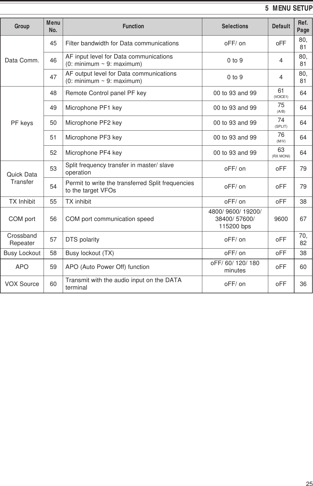
![368 COMMUNICATING AIDSTRANSMISSIONVOX (VOICE-OPERATED TRANSMIT)VOX eliminates the necessity of manually switchingto the transmission mode each time you want totransmit. The transceiver automatically switches totransmission mode when the VOX circuitry sensesthat you have begun speaking into the microphone.When using VOX, develop the habit of pausingbetween thoughts to allow the transceiver to dropback to reception mode briefly. You will then hear ifanybody wants to interrupt, plus you will have a shortperiod to gather your thoughts before speaking again.Your listeners will appreciate your consideration aswell as respect your more articulate conversation.VOX can be switched ON and OFF independently forCW and the other modes, excluding FSK.Press [VOX/ 8] to toggle between VOX ON and OFF.• “VOX” appears when the VOX function is ON.■Microphone Input LevelTo enjoy the VOX function, take the time toproperly adjust the gain of the VOX circuit. Thislevel controls the capability of the VOX circuit todetect the presence or absence of your voice.In CW mode, this level cannot be adjusted.1Select USB, LSB, FM, or AM mode.2Press [VOX/ 8] to switch the VOX function ON.• “VOX” appears.3Press [VOX/ 8] (1 s).• The current VOX gain appears on the sub-display.4While speaking into the microphone using yournormal tone of voice, adjust the setting (defaultis 4) using the MULTI control until thetransceiver reliably switches to transmissionmode each time you speak.• The selectable gain range is from 0 to 9.• The setting should not allow backgroundnoise to switch the transceiver to transmitmode.Note: The VOX gain level can be adjusted even if VOX isswitched OFF or while you are transmitting.■Delay TimeIf the transceiver returns to reception mode tooquickly after you stop speaking, your final wordmay not be transmitted. To avoid this, select anappropriate delay time that allows all of yourwords to be transmitted without an overly longdelay after you stop speaking.1Select USB, LSB, FM, or AM mode.2Press [VOX/ 8] to switch the VOX function ON.• “VOX” appears.3Press [KEY/ DELAY] (1 s).• The current setting appears on the sub-display. The default is 50 (1500 ms).4While speaking into the microphone using yournormal tone of voice, turn the MULTI controlsuch that the transceiver switches to receptionmode after you have stopped talking.• The selectable range is from 5 to 100(150 ms to 3000 ms) in steps of 5, or OFF.5Press [MTR/ CLR] to store the parameter andexit the setting mode.■Anti-VOX adjustmentThe TS-480 transceiver has a DSP IC to improveand customize incoming/ outgoing audio signals.When VOX function is turned ON, the DSP ICadjusts the Anti-VOX level automatically,comparing the reception sound level andmicrophone input level. So, you never have toworry about adjusting the anti-VOX level.■VOX SourceAlthough microphone is normally used to performthe VOX transmission, you can also utilize AFinput of the DATA connector (pin 1) on the TX/ RXunit {page 81}. When the transceiver detects theaudio signal on the pin 1 of DATA connector, thetransceiver automatically transmits.1Select USB, LSB, FM, or AM mode.2Press [VOX/ 8] to switch the VOX function ON.• “VOX” appears.3Press [MENU/ F.LOCK] and turn MULTIcontrol to select Menu No. 60.4Press [ ] to switch the VOX with DATA inputfunction ON.5Turn MULTI control to select Menu No. 46.6While sending AF signal to pin 1 of DATAconnector, adjust the value (default is 4) using[ ]/ [ ] until the transceiver reliably switchesto transmit mode each time you send AF signalto pin 1 of DATA connector.Note: VOX function does not work even if you speak into themicrophone. However, you can transmit with the Mic [PTT].](https://usermanual.wiki/JVC-KENWOOD/33101110.Users-Manual-1/User-Guide-366710-Page-41.png)
![378 COMMUNICATING AIDSSPEECH PROCESSORThe Speech Processor levels out large fluctuations inyour voice while you speak. When using SSB, FM, orAM mode, this leveling action effectively raises theaverage TX power, resulting in a moreunderstandable signal. The amount of voicecompression is fully adjustable. You will notice thatusing the Speech Processor makes it easier to beheard by distant stations.1Select USB, LSB, FM, or AM mode.2Press [PROC/ 9] to turn the Speech ProcessorON.• “PROC” appears.3Press [PROC/ 9] (1 s) to enter the SpeechProcessor input level adjustment mode.4As you speak into the microphone, turn theMULTI control so that the compression meterindicates that the compression level is around10 dB while you speak.• Using higher compression will not improve yoursignal clarity or apparent signal strength.Excessively compressed signals are moredifficult to understand due to distortion and areless pleasant to hear than signals with lesscompression.5Press [PROC/ 9] (1 s) to exit the SpeechProcessor input level adjustment mode.6Press [MIC/ 5/ RF.G] to enter the SpeechProcessor output level adjustment mode.• As you speak into the microphone, turn theMULTI control so that the ALC meter reflectsaccording to your voice level but does notexceed the ALC limit. Press [MIC/ 5/ RF.G] toexit when you finish the adjustment mode.XIT (TRANSMIT INCREMENTAL TUNING)Similar to RIT, XIT provides the ability to change yourtransmission frequency by ±9.99 kHz in steps of 10 Hzwithout changing your reception frequency. If the FineTuning function is ON, the frequency step sizebecomes 1 Hz.1Press [XIT].• “XIT” and the XIT offset appear.2If required, press [CL] to reset the XIT offset to 0.3Turn the RIT/ XIT control to change your transmitfrequency.4To turn XIT OFF, press [XIT].• “XIT” and offset frequency display disappear.The transmission frequency is returned to thefrequency that was selected prior to step 1.Note:◆If the Fine Tuning function is ON, you can adjust the frequencywithin ±9.99 kHz.◆The frequency shift set by the XIT control is also used by the RITfunction. Therefore, changing or clearing the XIT offset alsoaffects the RIT offset.◆When the XIT frequency exceeds the limit of availabletransmission frequency, the transceiver automatically stopstransmitting.TX powerTX powerTimeTimeSpeech Processor OFFSpeech Processor ON](https://usermanual.wiki/JVC-KENWOOD/33101110.Users-Manual-1/User-Guide-366710-Page-42.png)
![388 COMMUNICATING AIDSCUSTOMIZING TRANSMISSION SIGNALCHARACTERISTICSThe quality of your transmission signal is important,regardless of which on-air activity you pursue.However, it is easy to be casual and overlook this factsince you don’t listen to your own signal.The following sub-sections provide information thatwill help you tailor your transmission signal.■TX Filter Bandwidth (SSB/ AM)Use Menu No. 20 to select one of the following TXfilter bandwidths: 2.0 kHz or 2.4 kHz (default).yalpsiD htdiwdnaB ycneuqerfdnabssaP0.2zHk0.2zH0052~0054.2zHk4.2zH0072~003■TX Equalizer (SSB/ FM/ AM)Use Menu No. 19 to change the transmissionfrequency characteristics of your signal. You canselect from one of 6 different transmission profilesincluding the default flat response. Selecting any ofthe following items from the Menu causes “EQsssssT”to appear on the display.• Off (oFF):The default frequency response for SSB, FM,and AM.• High boost 1 (Hb1)/ High boost 2 (Hb2):Emphasizes higher audio frequencies; effectivefor a bassy voice. High boost 2 does notreduce the low frequency as much as Highboost 1.• Formant pass (FP):Improves clarity by suppressing audiofrequencies outside the normal voice frequencyrange.• Bass boost 1 (bb1)/ Bass boost 2 (bb2):Emphasizes lower audio frequencies; effectivefor a voice with more high frequencycomponents. Bass boost 2 emphasises morelow frequency response.• Conventional (c):Emphasizes by 3 dB frequencies at 600 Hzand higher.• User (U):Reserved for the optional ARCP software.Off is programmed at the factory as a default.Frequency Response CurvesTRANSMIT INHIBITTransmit Inhibit prevents the transceiver from beingplaced in transmission mode. No signal can betransmitted when this function is ON even if Mic [PTT]is pressed.• TX Inhibit OFF: Transmission is allowed.• TX Inhibit ON: Transmission is not allowed.Switch the function ON or OFF via Menu No. 55.The default is OFF.BUSY LOCKOUTBusy Lockout prevents the transceiver from beingplaced in transmit mode. Transmission is not allowedif the current operating frequency is busy (in otherwords, the squelch is open).• Busy Lockout OFF: Transmission is allowed.• Busy Lockout ON: Transmission is not allowed.Switch the function ON or OFF via Menu No. 58.The default is OFF.CHANGING FREQUENCY WHILE TRANSMITTINGMoving your frequency while transmitting is usuallyan unwise practice due to the risk of interfering withother stations. However, if necessary, by using theTuning control you can change the operatingfrequency while transmitting. You also can changethe XIT offset frequency while in transmission mode.While transmitting, if you select a frequency outsidethe transmission frequency range, the transceiver isautomatically forced to return to the reception mode.If you selected transmission mode by pressing Mic[PTT], transmission will not resume until you select afrequency inside the transmission frequency range, atwhich time you must release and press Mic [PTT]again.0.7 2.2AmplitudeAudio frequency (kHz)Bass boostHigh boostOffConventionalFormant pass](https://usermanual.wiki/JVC-KENWOOD/33101110.Users-Manual-1/User-Guide-366710-Page-43.png)
![398 COMMUNICATING AIDSCW BREAK-INBreak-in allows you to transmit CW without manuallyswitching between transmission and receptionmodes. Two types of Break-ins are available: SemiBreak-in and Full Break-in.Semi Break-in:When the key contacts open, the transceiverautomatically waits for the passage of the time periodthat you have selected. The transceiver then returnsto reception mode.Full Break-in:As soon as the key contacts open, the transceiverreturns to reception mode.USING SEMI BREAK-IN OR FULL BREAK-IN1Press [MODE] until you select CW mode.• “CW” or “CWR” appears.2Press [VOX/ 8].• “VOX” appears.3Press [KEY/ 6/ DELAY] (1 s).• The current setting (Full or delay time)appears. The default is FBK (Full Break-in).4Turn the MULTI control to select FBK (FullBreak-in) or a delay time for Semi Break-in.• Delay time ranges from 5 to 100 (50 ms to1000 ms) in steps of 5.5Begin sending.• The transceiver automatically switches totransmission mode.•When FBK (Full Break-in) is selected:The transceiver immediately switches toreception mode when the key opens.•When a delay time is selected:The transceiver switches to reception modeafter the delay time that you have selected haspassed.6Press [MTR/ CLR] to exit.Note: Full Break-in cannot be used with the TL-922/ 922A linearamplifier.ELECTRONIC KEYERThis transceiver has a built-in electronic keyer thatcan be used by connecting a keyer paddle to thetransceiver’s rear panel. Refer to “Keys for CW(PADDLE and KEY)” {page 7} for details regardingthis connection. The built-in keyer supports lambic(squeeze) operation.CHANGING KEYING SPEEDThe keying speed of the electronic keyer is fullyadjustable. Selecting the appropriate speed isimportant in order to send error-free CW that otheroperators can copy solidly. Selecting a speed that isbeyond your keying ability will only result in mistakes.You will obtain the best results by selecting a speedthat is close to the speed used by the other station.1Press [MODE] until you select CW mode.• “CW” or “CWR” appears.2Press [KEY/ 6/ DELAY].• The current keying speed appears. The defaultis 20 (WPM).3While keying the paddle and listening to the TX(transmission) sidetone, turn the MULTI control toselect the appropriate speed.• The speeds range from 10 (WPM) to 60 (WPM),in steps of 1 (WPM). The larger the number, thefaster the speed.4Press [KEY/ 6/ DELAY] again to complete thesetting.Note: When using the semi-automatic “Bug” function, the selectedspeed applies only to the rate that dots are sent.AUTO WEIGHTINGThe electronic keyer can automatically change thedot/ dash weighting. Weighting is the ratio of dashlength to dot length. The weighting changes withyour keying speed, thus making your keying easierfor other operators to copy.Access Menu No. 35 to select “auto” or “2.5” ~ “4.0”(in steps of 0.1) fix weight ratio. The default is “auto”.When the fix weight ratio is selected, the dot/ dashweight ratio is locked regardless of the keying speed.■Reverse Keying Weight RatioAuto Weighting increases the weighting as youincrease your keying speed. However, theelectronic keyer also can decrease the weightingas you increase your keying speed.To switch this function ON, access Menu No. 36,and select “on”. The default is OFF.esreveR gniyeK thgieW)MPW(deepSgniyeK52~01 54~62 06~64FFO8.2:10.3:12.3:1NO2.3:10.3:18.2:1](https://usermanual.wiki/JVC-KENWOOD/33101110.Users-Manual-1/User-Guide-366710-Page-44.png)
![408 COMMUNICATING AIDSBUG KEY FUNCTIONThe built-in electronic keyer also can be used as asemi-automatic key. Semi-automatic keys are alsoknown as “Bugs”. When this function is ON, dots aregenerated in the normal manner by the electronickeyer. Dashes, however, are manually generated bythe operator by holding the keyer paddle closed forthe appropriate length of time.To switch this function ON, access Menu No. 37 andselect “on”. The default is OFF.Note: When the Bug Key function is ON, CW Message Memory(see below) cannot be used.CW MESSAGE MEMORYThis transceiver has 3 memory channels for storingCW messages. Each memory channel can storeapproximately 50 characters (equivalent of 250 dots).These memory channels are ideal for storing contestexchanges that you want to send repeatedly. Storedmessages can be played back to check messagecontent or for transmitting.The electronic keyer has a function that allows youto interrupt playback and manually inject your ownkeying. To switch this function ON, access MenuNo. 33 and select “on”. The default is OFF.The electronic keyer can also repeatedly play backthe message that you stored. To switch this functionON, access Menu No. 31 and select “on”. Thedefault is OFF.For repetitive message playback, you can changethe interval between each series of messages.Use Menu No. 32 and select the time in the rangeof 0 to 60 seconds in steps of 1 second {page 39}.Note:◆This function cannot be used when the Bug Key function isON.◆Operating the keyer paddle with Menu No. 33 OFF cancelsmessage playback. Even if message playback does not stopbecause of your keying start timing, you can cancel playbackby pressing [MTR/ CLR].■Storing CW Messages1Press [MODE] until you select CW mode.• “CW” or “CWR” appears.2If VOX is ON, press [VOX/ 8].• “VOX” disappears {page 39}.3Press [CH1/ 1/ REC] (1 s), [CH2/ 2/ REC](1 s) or [CH3/ 3/ REC] (1 s) to select a memorychannel to be recorded.• If the Constant Recording is ON (Menu No.30), you cannot store a message to CH3{page 70}.4Begin sending using the keyer paddle.• The message you send is stored in memory.5To complete the message storage, press[MTR/ CLR] to stop.• When the memory becomes full, recordingautomatically stops.Note: If you do not operate the keyer paddle after starting torecord a message, a pause is stored in the channel.■Checking CW Messages without Transmitting1Press [MODE] until you select CW mode.• “CW” or “CWR” appears.2If VOX is ON, press [VOX/ 8] to switch it OFF.3Press [CH1/ 1/ REC], [CH2/ 2/ REC] or[CH3/ 3/ REC] to select the channel to beplayed back.• The message is played back.• To play back the messages stored in theother channels in sequence, press thecorresponding channel keys duringplayback. Up to 3 channels can be queuedat the same time.• While playing back the messages, you canalso adjust the keyer speed by pressing[KEY/ 6/ DELAY] and turning the MULTIcontrol.• To interrupt playback, press [MTR/ CLR].■Transmitting CW MessagesMessages can be transmitted using Semi Break-in/ Full Break-in or manual TX/ RX switching.1Press [MODE] until “CW” or “CWR” appears.2To use Semi Break-in/ Full Break-in, press[VOX/ 8].• “VOX” appears.3Press [CH1/ 1/ REC], [CH2/ 2/ REC] or[CH3/ 3/ REC] to select the channel to beplayed back.• The message is played back andtransmitted automatically.• To transmit the messages stored in theother channels in sequence, press thecorresponding channel keys duringplayback. Up to 3 channels can be queuedat the same time.• While playing back the messages, you canalso adjust the keyer speed by pressing[KEY/ 6/ DELAY] and turning the MULTIcontrol.• To interrupt transmission, press [MTR/ CLR].](https://usermanual.wiki/JVC-KENWOOD/33101110.Users-Manual-1/User-Guide-366710-Page-45.png)
![418 COMMUNICATING AIDS■Changing the Inter-message Interval TimeFor the message playback repeat, access MenuNo. 31 and select “on”. You can also change theinterval playback time of the message. AccessMenu No. 32 and select the time in the range of 0to 60 seconds in steps of 1 second.Note: Menu Nos. 31 and 32 settings are shared with the voicecommunication modes when the optional VGS-1 is installed.■Changing the Sidetone VolumeTurning the AF control does not change the CWsidetone playback volume. To change the CWsidetone volume, access Menu No. 13 and select“oFF”, or “1” to “9”.■Insert KeyingIf you operate a CW keyer manually while playingback a recorded CW message, the transceiverstops playing back the message. However, duringcontests or regular QSOs, you may sometimeswant to insert a different number or message at acertain point in the recorded message.In this case, first record the CW message as usual{page 40}, without the number or message youwant to insert. Then, access Menu No. 33 andselect “on”.Now if you operate a CW keyer while you playback a recorded message, the transceiver pausesthe playback of the recorded message, instead ofstopping it. When you finish sending the numberor message with the keyer, the transceiverresumes playback of the message.FREQUENCY CORRECTION FOR CWIf you operate both SSB and CW modes, you wouldsometimes use SSB mode (USB or LSB) just towatch and listen to CW signals. It is fine just tomonitor those CW signals but you have experiencedthat changing the mode from SSB to CW results inlosing the target CW signal. This is because thefrequency on the display always shows the truecarrier frequency for all modes. If you want thetransceiver to shift the reception frequency to tracethe receiving CW signal when changing the modefrom SSB (USB or LSB) to CW, switch this functionON. The transceiver shifts the reception frequencywhen changing the mode from SSB to CW, so youcan still hear the target signal and instantly transmitthe signal in CW without adjusting the frequency.1Press [MENU/ F.LOCK], then turn the MULTIcontrol to access Menu No. 40.2Press [ ] to select “on”.3Press [MENU/ F.LOCK] to store the settings andexit the Menu mode.AUTO CW TX IN SSB MODEIf you operate both SSB and CW modes, you canconfigure the transceiver to change the operatingmode from SSB (USB or LSB) to CW and thentransmit in CW mode automatically when you operatethe CW keyers.1Press [MENU/ F.LOCK], then turn the MULTIcontrol to access Menu No. 39.2Press [ ] to select “on”.3Press [MENU/ F.LOCK] to store the settings andexit the Menu mode.Note: You must switch the CW break-in function ON to change themode and transmit in CW mode {page 39}.MIC UP/ DWN KEY PADDLE MODEThis function allows you to send CW messagewithout using an optional paddle {page 7}. Mic [UP]key can be used as dot paddle and Mic [DWN] keycan be used as a dash paddle.To activate Mic UP/ DWN key Paddle Mode:1Turn the transceiver OFF.2Press Mic [UP] or Mic [DWN] + [ ] (POWER).• Press and hold Mic [UP] to send dots or Mic[DWN] to send dashes in CW mode.To exit Mic UP/ DWN key Paddle Mode, perform step1 and 2 again.CW REVERSE (RECEPTION)This function pivots the BFO from the default position(USB) to another position (LSB) in CW mode. It issometimes effective to remove the interfering signalsfrom the IF passband by pivoting the BFO.1Press [MODE] until “CW” appears.2Press [MODE] (1 s).• “CW” changes to “CWR”.3To recover the default BFO position, press[MODE] (1 s) again.• “CWR” changes to “CW”.](https://usermanual.wiki/JVC-KENWOOD/33101110.Users-Manual-1/User-Guide-366710-Page-46.png)
![42SPECIALIZED COMMUNICATIONSRADIO TELETYPE (RTTY)RTTY is the data communications mode with thelongest history. It was originally designed for use withmechanical teletypewriters which were often usedbefore personal computers became common. Nowyou can easily start operating RTTY with a personalcomputer and MCP. Unlike Packet, each time youtype a letter, it is transmitted over the air. What youtyped is transmitted and displayed on the computerscreen of the recipient.RTTY operation uses frequency shift keying (FSK)and the 5-bit Baudot code or the 7-bit ASCII code totransmit information.For the cable connections, refer to “RTTYOPERATION” {page 80}.For further information, consult reference booksabout Amateur Radio.1Access Menu No. 41 and select an FSK shift.• FSK shift is the difference in frequenciesbetween a mark and a space.• The 170 Hz shift (default) is normally used onthe Amateur bands for the RTTY.2Access Menu No. 42 and select a key-downpolarity.• Select “oFF” (default) to transmit a mark whenkeying down or “on” to transmit a space.3Access Menu No. 43 and select high tone(2125 Hz) or low tone (1275 Hz) for mark.• High tone (default) is commonly usednowadays.4Select an operating frequency.5Press [MODE] to select FSK mode {page 19}.• If necessary, use Menu No. 47 to configure theappropriate audio level from your MCP.The AF control cannot be used to adjust theaudio level from your MCP.6Some stations may be operating in Reverse shift.In this case, press [MODE] (1 s) to reverse theshift (the upper sideband is used).• “FSR” appears.• Traditionally, the lower sideband is used forFSK operation. Press [MODE] (1 s) again toreturn to the lower sideband. “FSK” appears.7Follow the instructions provided with your MCPand enter a command from your computer totransmit.• The LED changes from green (RX) to red (TX).8Begin sending data from your computer.• Press [PWR/ 4/ TX MONI] (1 s) to monitor yoursignals. Press [PWR/ 4/ TX MONI] (1 s) againto quit this function.9When finished transmitting, enter a command fromyour computer to return to reception mode.• The LED changes from red (TX) to green (RX).The following frequencies (measured in kHz)commonly used for RTTY operation:adanaC/.A.S.U 1noigeRURA )acirfA/eporuE(0481~00812481~8381)0953:XD(5463~50630263~0853)0407:XD(0017~08075407~530705101~0410105101~041015.99041~070415.99041~0804101181~0018190181~1018100112~0701202112~0801203942~0294292942~0292205182~0708205182~05082](https://usermanual.wiki/JVC-KENWOOD/33101110.Users-Manual-1/User-Guide-366710-Page-47.png)