JVC KENWOOD 33101110 HF Transceiver with Scanning Receiver User Manual 0 Front page
JVC KENWOOD Corporation HF Transceiver with Scanning Receiver 0 Front page
UserManual.wiki
>
JVC KENWOOD
>
33101110 User Manual
>
Users Manual 2
Contents
1.
Users Manual 1
2.
Users Manual 2
Users Manual 2
Navigation menu
Upload a User Manual
Namespaces
Wiki Guide
HTML
PDF
Info
Views
User Manual
Discussion / Help
Navigation
![45REJECTING INTERFERENCEhtdiwdnabretliFFI htdiwdnab)FA(retliFPSDNC701-FY zH072 C701-FY zH005 NS701-FY zHk8.1 zH003~ zH006~ zHk0.2~——— )lamroN(zHk4.2——✓)lamroN(zHk8.1—✓—)RAN(zH005 zHk4.2)lamroN(✓—— zH072)RAN( )lamroN(zHk4.2—✓✓ )RAN(zH005 zHk8.1)lamroN(✓—✓zH072)RAN( )lamroN(zHk8.1✓✓—zH072)2RAN(zH005)RAN(zHk4.2)lamroN(■FMIn FM mode, you cannot change the reception IF filterbandwidth. The bandwidth is fixed at 12 kHz.IF SHIFT (SSB/ CW/ FSK)Shifting the center frequency of the filter pass band isan additional method of removing adjacent frequencyinterference. Shifting this center frequency does notchange the current reception frequency.To remove interference that is higher in frequencythan the desired signal, turn the IF SHIFT controlcounterclockwise. To remove interference that islower in frequency than the desired signal, turn the IFSHIFT control clockwise.Desired signal Interfering signalIF pass bandIF FILTERThe IF filters are designed for selecting the exactrange of intermediate frequencies that are sent to thenext stage in the receive circuit. Interferenceadjacent to the desired signal can be reduced byselecting a narrow bandwidth filter and/ or shifting thecenter frequency of the filter.To more effectively remove interference, combine theIF filtering and the DSP filtering (AF) described onpages 46 and 47.CHANGING THE IF FILTER BANDWIDTHWhen adjacent frequency interference is present atboth sides of the desired signal, narrowing IF filterbandwidth may be the best way to remove theinterference. Changing the filter bandwidth will noteffect the current reception frequency.You can install 2 optional IF filters for SSB, CW, andFSK modes. After installing the optional filters{page 83}, the transceiver automatically recognizeswhat type of optional filters are installed.■SSB/ AMWhen you operate the transceiver in SSB or AMmode, you can manually select the wide or narrowfilter.Press [FIL/ NAR] (1 s) to select another IF filter.•Each press of [FIL/ NAR] (1 s) changes “ ”(Normal) / “NAR”, then back to “ ” (Normal).•If Menu No. 17 is ON (default is OFF) and 2 IFfilters have been installed, you can selectsecondary IF filter. In this case, each press of[FIL/ NAR] (1 s) changes “ ” (Normal) / “NAR”/ “NAR 2”, then back to “ ” (Normal).edoM htdiwdnabretlifFIlamroN worraNBSSzHk4.2 zHk8.11/zH0052zH072/3MAzHk0.6zHk4.21Optional YF-107SN filter must be installed.2Optional YF-107C filter must be installed and Menu No. 17 mustbe set to ON.3Optional YF-107CN filter must be installed and Menu No. 17must be set to ON.■CW/ FSKWhen you operate in CW or FSK mode, the wide filteror narrow filter is automatically selected according tothe DSP filter bandwidth that you select.The following table describes how the optional filter isselected as you change the bandwidth of DSP filter.You cannot manually select the IF filter. To changethe DSP filter bandwidth, refer to “CHANGING THEDSP FILTER BANDWIDTH” {page 46}.](https://usermanual.wiki/JVC-KENWOOD/33101110.Users-Manual-2/User-Guide-366712-Page-2.png)
![4610 REJECTING INTERFERENCEDSP FILTERSKENWOOD digital signal processing (DSP)technology is adapted to this transceiver. Using DSPfiltering (AF), you can control the bandwidth, cancelthe multiple jamming beat, and reduce the noise levelusing DSP filtering technology.CHANGING THE DSP FILTER BANDWIDTHFor improving interference reduction capability, thistransceiver also provides the DSP filtering (AF) alongwith IF filters. When in SSB, FM, or AM mode, youcan change the filter bandwidth by altering its lowand/ or high cut-off frequency. For CW and FSKmodes, you can change the filter bandwidth bydirectly specifying a bandwidth. Changing the DSPfilter bandwidth (AF) does not affect the currentreception frequency.■SSB/ FM/ AM1Press [MODE] to select SSB, FM, or AM mode.2Press [FIL/ NAR].• The current high-cut filter frequency for themode appears on the sub-display.3Turn the MULTI control clockwise to raise thehigh cut-off frequency, or counterclockwise tolower the high cut-off frequency.ff4Press [FIL/ NAR] again.• The current low-cut filter frequency appears.5Turn the MULTI control clockwise to raise thelow cut-off frequency, or counterclockwise tolower the low cut-off frequency.6To return to the normal operation, press[FIL/ NAR] or [MTR/ CLR].fftsujdA edoM )zH(snoitceleSycneuqerFIH/BSS MF,0061,0041,0021,0001 ,0042,0022,0002,0081 0043,0003,0082,0062 0005,0004,)tluafed(MA ,0004,)tluafed(0003,0052 0005OL/BSS MF,002,)tluafed(001,05,0 ,007,006,005,004,003 0001,009,008MA005,002,)tluafed(001,0Note:◆The cut-off frequencies (LO) can be adjusted independentlyfor each operating mode. When you change the operatingmode, the previous setting is recalled for each operatingmode.◆When the DSP filter for data communication (Menu No. 45) isON, you cannot change the DSP filter bandwidth. Select“oFF” to adjust the DSP filter bandwidth.■CW/ FSK1Press [MODE] to select CW or FSK mode.2Press [FIL/ NAR].• The current DSP filter bandwidth (AF)appears.3Turn the MULTI control clockwise to increase(wider) the bandwidth, or counterclockwise todecrease (narrower) the bandwidth.Interferingsignal Desiredsignal Interfering signalPass band (AF)edoM )zH(snoitceleShtdiwdnaB tluafeD )zH(WC ,004,003,002,051,001,08,05 0002,0001,006,005 006KSF0051,0001,005,05200514As for CW, you can further adjust the RX pitchfrequency. Access Menu No. 34 and turn theMULTI control to adjust the RX pitch frequencyfrom 400 to 1000 Hz in steps of 50 Hz. Thedefault RX pitch frequency is 800 Hz {page 29}.5To return to the current operating mode, press[MTR/ CLR] or [FIL/ NAR].](https://usermanual.wiki/JVC-KENWOOD/33101110.Users-Manual-2/User-Guide-366712-Page-3.png)
![4710 REJECTING INTERFERENCEBEAT CANCEL (SSB/ FM/ AM)Two types of Beat Cancel DSP filters are available.Beat Cancel 1 (BC1) is effective for removing a weakbeat or continuous beat signals. Beat Cancel 2(BC2) is effective for removing intermittient beatsignals, such as CW signals.BeforeInterferingtoneAfterFilter pass band (AF)DesiredsignalPress [BC/ CW.T] to cycle through Beat Cancel 1,Beat Cancel 2, and OFF.•“1tBC” or “BCs2” appears when the Beat Cancelfunction is ON.•The interfering beat signals are removed.NOISE REDUCTION (ALL MODES)This transceiver provides 2 types of Noise Reductionfunctions (NR1 and NR2) for reducing random noisewhich interferes with the desired signal. Trying themboth is the easiest way to judge which function worksmore effectively under the current conditions.Normally, select NR1 (Line Enhanced) in SSB modeand NR2 (SPAC) in CW mode.Press [N.R./ LEVEL] to toggle between NR1, NR2,and OFF.•“1tttttNR” or “NRsssss2” appears, depending on whichtype of noise reduction filter is selected.■Setting the NR1 Level AdjustmentThe NR1 (Line Enhanced Method) uses anadaptive filter to reduce the noise element fromthe received signals. When the S/N ratio isreasonably good in SSB, using the NR1 willimprove the S/N further.While NR1 is ON, you can further adjust the noisereduction level by pressing [NR] (1 s), then turn theMULTI control to select the level from 1 to 9 orAUTO. The default is AUTO.■Setting the NR2 Time ConstantYou can change the correlation time for NR2(SPAC). When in SSB mode, select thecorrelation time that allows you to hear signalswith clarity. When receiving CW, it is best toselect the longest correlation time that allowsreliable reception. The longer the correlation time,the better the S/N ratio.When NR2 is ON, press [NR] (1 s), then turn theMULTI control to select the correlation time from2 ms to 20 ms. The default is 20 ms.Note: Using Noise Reduction 2 in SSB mode may lower theclarity of signals or induce pulse noise, depending on theconditions.NOISE BLANKERNoise Blanker was designed to reduce pulse noisesuch as that generated by automobile ignitions.Noise Blanker does not function in FM mode.Press [NB/T/ 7] to toggle the Noise Blanker ON andOFF.• “NB” appears when the function is ON.You can further adjust the Noise Blanker level from1 to 10. The default level is 6.Press [NB/T/ 7] (1 s), then turn the MULTI control toadjust the Noise Blanker level.• “NB LV.” and the current level appear on the sub-display.Note: Noise Blanker is available only for SSB, CW, FSK, and AMmodes.DIGITAL NOISE LIMITER (DNL)Digital Noise Limiter (DNL) is designed to reducepulse noise such as that generated by automobileignitions. Try this function when the Noise Blankerfunction cannot remove the pulse noises effectively.Digital Noise Limiter does not function in FM mode.Press [DNL] to toggle the DNL ON and OFF.• “DNL” appears when the function is ON.You can further adjust the DNL level from 1 to 3.The default level is 2.Press [DNL] (1 s), then turn the MULTI control toadjust the Digital Noise Limiter level.• The current level appear on the sub-display.Note:◆Digital Noise Limiter is available only for SSB, CW, FSK, and AMmodes.◆Depending on a pulse type, the DNL function may not be able toremove the noise.◆Turning the DNL function ON when there is no pulse-type noiseand the signal is relatively strong, it could degrade the signalreadabilty.◆When the DNL function is ON, the high-cut filter frequencybecomes 3.0 kHz regardless of the DSP filter settings.◆The DNL function can be used with the Beat Cancel (BC), NoiseReduction (NR) , and Noise Blanker functions at the same time.](https://usermanual.wiki/JVC-KENWOOD/33101110.Users-Manual-2/User-Guide-366712-Page-4.png)
![4810 REJECTING INTERFERENCEDSP FILTER FOR DATA COMMUNICATION(SSB/ FM)The DSP filter for Data Communication is designed toimprove the reception tone readability, especially forPSK31 and other new digital modes.1Press [MENU/ F.LOCK] and turn the MULTIcontrol to select Menu No. 45.2Press [ ]/ [ ] to select “oFF” or “on” (default isOFF).While Menu No. 45 is ON:1Press [FIL/ NAR].• “WDH -- nnnn” (where “nnnn” is DSP filterbandwidth in Hz) appears.2Turn MULTI control to select the desiredbandwidth.3Press [FIL/ NAR].• “CTR -- nnnn” (where “nnnn” is a center filterfrequency in Hz) appears.4Turn MULTI control to select the desired centerfrequency for the filter.5Press [FIL/ NAR] to complete the settings.The following center frequencies and bandwidthcombinations are available.1000/ 1500 Hz is used for the PSK31 operation and2210 Hz is used for the RTTY operation.retneC )zH(.qerF )zH(htdiwdnabretliF000105001052005000100510042005105001052005000100510042012205001052005000100510042Note: While Menu No. 45 is ON, the DSP filter bandwidth {page 46}cannot be changed.DSP RX MONITORThe DSP RX Monitor function temporarily cancels IFfilter selection and DSP filter settings so that you canconfirm the conditions of current reception frequencynearby.To use the DSP RX Monitor function, first assign thePF key on the panel (or Mic PF keys) {page 64}.1Press [MENU/ F.LOCK] and turn the MULTIcontrol to select Menu No. 48.2Press [ ]/ [ ] to select “64”.3Press [MENU/ F.LOCK] to store the setting andexit the Menu Mode.4Press [PF].• While pressing [PF], the transceiver cancels IFfilter selection and DSP filter settings to its defaultvalues. When you release [PF], the transceiverrecovers the IF and DSP filter settings.](https://usermanual.wiki/JVC-KENWOOD/33101110.Users-Manual-2/User-Guide-366712-Page-5.png)
![4910 REJECTING INTERFERENCEPRE-AMPLIFIERSwitching the Pre-amplifier OFF may help reduceinterference from adjacent frequencies.Press [ATT/PRE/ ANT 1/2] to cycle through “ATT” /“PRE” / “ ” (OFF) then return to “ATT”. Select“PRE” to turn the pre-amplifier ON. When it is ON,the signal is amplified approximately 12 dB.• “PRE” appears when the function is ON.The ON/ OFF setting will be automatically stored inthe current band. Each time you select the sameband, the same setting will be automatically selected.The frequency range of each band is provided in thetable under “ATTENUATOR”.ATTENUATORThe Attenuator reduces the level of received signals.This function is useful when there is stronginterference from adjacent frequencies.Press [ATT/PRE/ ANT 1/2] to cycle through “ATT” /“PRE” / “ ” (OFF) then return to “ATT”. Select“ATT” to activate the attenuator function. When it isON, the signal is attenuated approximately 12 dB.• “ATT” appears when the function is ON.The ON/ OFF setting will be automatically stored inthe current band. Each time you select the samefrequency band, the attenuator setting will beautomatically recalled.The frequency range of each band is shown below.sdnaBycneuqerF )zHM( reifilpma-erP )tluafeD( rotaunettA )tluafeD(5.2~30.0FFOFFO1.4~5.2FFOFFO9.6~1.4FFOFFO5.7~9.6FFOFFO5.01~5.7NOFFO5.41~5.01NOFFO5.81~5.41NOFFO5.12~5.81NOFFO5.52~5.12NOFFO0.03~5.52NOFFO0.06~0.03NOFFO](https://usermanual.wiki/JVC-KENWOOD/33101110.Users-Manual-2/User-Guide-366712-Page-6.png)
![50MEMORY FEATURESMEMORY CHANNELSThe transceiver provides you with 100 memorychannels, numbered 00 to 99, for storing operatingfrequency data, modes and other information.Memory channels 00 to 89 are called ConventionalMemory Channels. Memory channels 90 to 99 aredesigned for programming VFO tuning ranges andscan ranges. The data you can store is listed below.Conventional memory channels are used for storingdata you will often recall. For example, you maystore the frequency where you regularly meet yourclub members.retemaraP lennahC 98~00 lennahC 99~09ycneuqerfXRseY seY1)xelpmis(ycneuqerfXTseYedomXRseY seY1)xelpmis(edomXTseYOFVelbammargorP seicneuqerfdnE/tratS oNseYezispetsycneuqerfXRseY seY )xelpmis(ezispetsycneuqerfXTseYycneuqerfenoTseYseYycneuqerfSSCTCseYseYFFO/NOSSCTC/enoT sutats seYseYemanyromeMseYseYtuokcoLlennahCyromeM FFO/NO seY1seY11Changing the data after recalling a memory channel overwrites thecontents of the channel.STORING DATA IN MEMORYThere are 2 methods used for storing transmission/reception frequencies and associated data in memorychannels 00 to 89. Use either method, depending onthe relationship of the reception and transmissionfrequencies you store:• Simplex channels:RX frequency = TX frequency• Split-frequency channels:RX frequency ≠ TX frequencyMemory channels 90 to 99 can also be used assimplex channels.Note: When RIT or XIT is ON, the frequency that includes the RIT orXIT offset will be stored.■Simplex Channels1Press [A/B / M/V] to select VFO A or VFO B.•“tA” or “tB” appears to show which VFOis selected.2Select the frequency, mode, etc. to be stored.3Press [QMI/ M.IN] (1 s) to enter Memory Scrollmode.• “M.SCR” appears.• To exit Memory Scroll mode and abort thestorage process, press [MTR/ CLR].4Turn the MULTI control, or press Mic [UP]/[DWN] to select a memory channel.• You can also select a channel by entering a2-digit number, such as 12, using thenumeric keys. Press [1], [2] for example.5Press [QMI/ M.IN] again to store the data.• The previous data stored in the channel isoverwritten.](https://usermanual.wiki/JVC-KENWOOD/33101110.Users-Manual-2/User-Guide-366712-Page-7.png)
![5111 MEMORY FEATURES■Split-Frequency Channels1Press [A/B / M/V] to select VFO A or VFO B.•“tA” or “tB” appears to show which VFOis selected.2Select the frequency, mode, etc. to be stored.• This frequency and mode will be used fortransmitting.3Press [A/B / M/V] to select the other VFO.4Select the reception frequency and mode.5Press [A=B/ SPLIT] (1 s).•“ ” appears.6Press [QMI/ M.IN] (1 s) to enter Memory Scrollmode.• To exit Memory Scroll mode and abort thestorage process, press [MTR/ CLR].7Turn the MULTI control, or press Mic [UP]/[DWN] to select a memory channel.• You can also select a channel by entering a2-digit number, such as 12, using thenumeric keys. Press [1], [2] for example.8Press [QMI/ M.IN] to store the data.• The previous data stored in the channel isoverwritten.Note: When subtone frequencies differ between TX and RXwhile performing memory-VFO split operation, the subtonefrequency for TX will be stored in the memory channel.MEMORY RECALL AND SCROLLThere are 2 modes which allow you to retrievefrequencies and associated data that you stored in amemory channel: Memory Recall and Memory Scroll.Memory Recall:In this mode, the transceiver receives and transmitsusing a frequency that you retrieve. You cantemporarily change the frequency and associateddata without overwriting the contents of the memorychannel when Menu No. 07 is ON (default is OFF).Memory Scroll:Use this mode to check the contents of the memorychannels without changing the current receptionfrequency. In this mode, frequencies you retrieve arenot used for receiving and transmitting.■Memory Recall1Press [A/B / M/V] (1 s) to enter Memory Recallmode.• The memory channel that was last selectedappears.2Turn the MULTI control, or press Mic [UP]/[DWN] to select a memory channel.• Continuously holding down Mic [UP]/[DWN] steps the transceiver through thememory channels until the key is released.• Memory channels which contain no data areskipped.• You cannot change memory channels whiletransmitting.3To exit Memory Recall mode, press[A/B / M/V] (1 s).Note: If Menu No. 7 is selected “on”, the frequency of the split-memory channel can be changed while using the TF-SETfunction.](https://usermanual.wiki/JVC-KENWOOD/33101110.Users-Manual-2/User-Guide-366712-Page-8.png)
![5211 MEMORY FEATURES■Memory Scroll1Press [QMI/ M.IN] (1 s) to enter Memory Scrollmode.•The memory channel that was last selectedappears.2Turn the MULTI control, or press Mic [UP]/[DWN] to step through the memory channels.• You can also change channels by entering a2-digit number. Press [8], [9] for example.3To exit Memory Scroll mode, press[MTR/ CLR].• The transceiver re-displays the memorychannel or VFO frequency that wasselected before you activated MemoryScroll.Note:◆While the transceiver is in Memory Scroll Mode, you canoperate the following controls and keys only: [QMI/ M.IN],[MTR/ CLR], numeric keys ([0] ~ [9]), Mic [UP]/ [DWN],Mic [PTT], AF control, SQL control, MULTI control and [ ](POWER).◆Do not press [QMI/ M.IN] again after entering Memory Scrollmode. Pressing [QMI/ M.IN] results in over-writing thecurrent VFO data to the memory channel you selected.■Temporary Frequency ChangesAfter retrieving frequencies and associated data inMemory Recall mode, you can temporarily changethe data without overwriting the contents of thememory channel.1Access Menu No. 07 and select “on”.• Skip this step when changing only theassociated data (not the frequency).2Recall a memory channel.3Change the frequencies and associated data.• Use only the Tuning control to select afrequency.4If necessary for future use, store the changeddata in another memory channel. Refer to“Channel ➡ Channel Transfer” {below}.Note: If Menu No. 7 is selected “on”, the frequency of the split-memory channel can be changed while using the TF-SETfunction.MEMORY TRANSFER■Memory \ VFO TransferAfter retrieving frequencies and associated datafrom Memory Recall mode, you can copy the datato the VFO. This function is useful, for example,when the frequency you want to monitor is nearthe frequency stored in a memory channel.1Recall the desired memory channel {page 51}.2Press [QMR/ MsssssVFO] (1 s).• When a simplex channel is recalled, thedata is copied to VFO A or VFO B,depending on which VFO was used to recallthe channel.• When a split channel is recalled, the RXdata is copied to VFO A and the TX data iscopied to VFO B.Note: Pressing [QMR/ MsVFO] (1 s) after temporarily changingthe retrieved data copies the new data to the VFO.■Channel \ Channel TransferYou can also copy channel information from onememory channel to another. This function isuseful when storing frequencies and associateddata that you temporarily change in MemoryRecall mode.1Recall the desired memory channel {page 51}.2Press [QMI/ M.IN] to enter Memory Scrollmode.• To exit Memory Scroll mode, press[MTR/ CLR].3Select the memory channel where you wouldlike the data copied, using the MULTI control.4Press [QMI/ M.IN] (1 s).98~00lennahC a98~00lennahCycneuqerfXR aycneuqerfXRycneuqerfXT aycneuqerfXTXRrofedoM aXRrofedoMXTrofedoM aXTrofedoMpetsycneuqerfXR apetsycneuqerfXRpetsycneuqerfXT apetsycneuqerfXTycneuqerfenoT aycneuqerfenoTycneuqerfSSCTC aycneuqerfSSCTCSSCTC/enoT sutatsFFO/NO aSSCTC/enoT sutatsFFO/NOemaNyromeM aemaNyromeMlennahCyromeM FFO/NOtuokcoL alennahCyromeM FFOtuokcoL](https://usermanual.wiki/JVC-KENWOOD/33101110.Users-Manual-2/User-Guide-366712-Page-9.png)
![5311 MEMORY FEATURES98~00lennahC a99~09lennahCycneuqerfXR aycneuqerfXR/XT )xelpmis(ycneuqerfXT aXRrofedoM aXR/XTrofedoM )xelpmis(XTrofedoM apetsycneuqerfXR aycneuqerfXR/XT )xelpmis(petspetsycneuqerfXT aycneuqerfenoT aycneuqerfenoTycneuqerfSSCTC aycneuqerfSSCTCSSCTC/enoT sutatsFFO/NO aSSCTC/enoT sutatsFFO/NOemaNyromeM aemaNyromeMlennahCyromeM FFO/NOtuokcoL alennahCyromeM FFOtuokcoL99~09lennahC a98~00lennahCycneuqerfXR/XT aycneuqerfXRaycneuqerfXTXR/XTrofedoM aXRrofedoMaXTrofedoMycneuqerfXR/XT )xelpmis(petsapetsycneuqerfXRapetsycneuqerfXTycneuqerfenoT aycneuqerfenoTycneuqerfSSCTC aycneuqerfSSCTCSSCTC/enoT sutatsFFO/NO aSSCTC/enoT sutatsFFO/NOemaNyromeM aemaNyromeMlennahCyromeM FFO/NOtuokcoL alennahCyromeM FFOtuokcoLWhen copying a memory channel 90 ~ 99 achannel 90 ~ 99, Memory Channel Lockout statuschanges to OFF, regardless of the original channelsettings.The tables above illustrate how data is transferredbetween memory channels.STORING FREQUENCY RANGESMemory channels 90 to 99 allow you to storefrequency ranges for VFO tuning and Program Scan.Program Scan is described in the next chapter. Totune or scan frequencies within a specified range,store the start and end frequencies for that range inadvance.1Press [A/B / M/V] to select VFO A or VFO B.2Select the desired start frequency.3Press [QMI/ M.IN] (1 s) to enter Memory Scrollmode.• To exit Memory Scroll mode and abort thestorage process, press [MTR/ CLR].4Turn the MULTI control, or press Mic [UP]/ [DWN]to select a memory channel in the range of 90 to99.• You can also select a channel by entering a2-digit number. Press [9], [0] for example.5Press [QMI/ M.IN] to store the start frequency inthe memory channel.• “ENDINPUT” appears on the sub-display.6Turn the Tuning control or MULTI control to selectthe end frequency.7Press [QMI/ M.IN] to store the end frequency inthe memory channel.• The previous data stored in the channel isoverwritten.■Confirming Start/ End FrequenciesUse this procedure to check the start and endfrequencies that you stored in channels 90 to 99.1Press [A/B / M/V] (1 s) to enter Memory Recallmode.2Turn the MULTI control, or press Mic [UP]/[DWN] to select a memory channel from 90 to99.3Press [] to check the start frequency and [ ]to check the end frequency.](https://usermanual.wiki/JVC-KENWOOD/33101110.Users-Manual-2/User-Guide-366712-Page-10.png)
![5411 MEMORY FEATURES■Programmable VFOUsing the start and end frequencies that youstored in channels 90 to 99, Programmable VFOrestricts the frequency range that you can tunewith the Tuning control. One application of thisfunction is to help you operate within theauthorized frequency limits of your license.1Press [A/B / M/V] (1 s) to enter Memory Recallmode.2Turn the MULTI control, or press Mic [UP]/[DWN] to select a memory channel from 90 to99.• You can also select a channel by entering a2-digit number. Press [ENT], [9], [0] forexample.Now you can only tune from the start frequency tothe end frequency, using the Tuning control.Note: Pressing Mic [UP]/ [DWN] or turning the MULTI controlchangies the memory channel number while in ProgrammableVFO mode.Memory Channel LockoutYou can lock out memory channels that you prefernot to monitor during Memory Scan. Memory Scan isdescribed in the next chapter {page 58}.1Press [A/B / M/V] (1 s) to enter Memory Recallmode.2Turn the MULTI control, or press Mic [UP]/ [DWN]to select the desired memory channel.• You can also select a channel by entering a2-digit number. Press [ENT], [3], [4] forexample.3Press [ENT] (1 s).• A dot appears beside the right-most digit of thememory channel number to indicate thechannel has been locked out.• Pressing [ENT] (1 s) toggles between addingand removing the channel from the scan list.ERASING MEMORY CHANNELSIf there are memory channels that you will not recallin the future, you may prefer erasing the contents ofthose channels.1Press [A/B / M/V] to enter Memory Recall mode.2Turn the MULTI control, or press Mic [UP]/ [DWN]to select the desired memory channel.• You can also select a channel by entering a2-digit number. Press [ENT], [3], [4] forexample.3Press [MTR/ CLR] (1 s).• A long beep sounds to confirm that the channeldata has been erased.MEMORY CHANNEL NAMEYou can assign a name to each memory channel. Amaximum of 8 alpha-numeric characters can bestored.1Press [A/B / M/V] (1 s) to enter Memory Recallmode.2Turn the MULTI control, or press Mic [UP]/ [DWN]to select a memory channel.3Press [QMR/ MsssssVFO].4Turn the MULTI control to select the desiredalpha-numeric character. You can move thecursor to the left by pressing [ ], or to the right bypressing [ ]. Press [CL] to erase the characterat the cursor.Note: You cannot name the Quick Memory channels.5After selecting all the necessary characters for thememory channel name, press [QMR/ MsssssVFO] tostore the name.6When you recall a memory channel with a name,the name is displayed on the sub-display alongwith the memory channel number {page 51}.Available alpha-numeric charactersABCDEFGH I JKLMNOPQRSTUVWXYZPS+–/0123456789“SP” represents a space character.](https://usermanual.wiki/JVC-KENWOOD/33101110.Users-Manual-2/User-Guide-366712-Page-11.png)
![5511 MEMORY FEATURESQUICK MEMORYQuick memory is designed to quickly and temporarilysave data without specifying a particular memorychannel. Use Quick memory to store data you willnot use in future operating sessions. For example, asyou tune across the band looking for DX, it isconvenient to store stations that you want to contact.You can quickly jump between several differentmemory channels as you monitor them.This transceiver provides 10 Quick memory channels(“0_” to “9_”) that can store the following data:dnaycneuqerfAOFV edomgnitarepo dnaycneuqerfBOFV edomgnitarepoFFO/NOTIRFFO/NOTIXycneuqerftesffoTIX/TIRhtdiwdnabretlifPSDFFO/NOreknalBesioNFFO/NOENIFnoitcudeResioNPSD 2/1/FFO lecnaCtaeBPSD 2/1/FFOretimiLesioNlatigiD 3~1/FFO snoitcnufXR/XTSTORING INTO QUICK MEMORYEach time you store a new frequency, all previouslystored frequencies are bumped to the next respectiveQuick memory channel. When all 10 memorychannels contain frequencies, storing one morefrequency bumps the contents of memory channel 9off the stack (the data is lost).The following diagram illustrates how the QuickMemory stacks the data in memory each time youpress [QMI/ M.IN].24.911Memory 014.005Memory 114.235Memory 221.250Memory 318.111Memory 450.015Memory 57.082Memory 629.610Memory 73.545Memory 814.195Memory 921.005Memory 024.911Memory 114.005Memory 214.235Memory 314.250Memory 418.111Memory 550.015Memory 67.082Memory 729.610Memory 83.545Memory 914.085Memory 021.005Memory 124.911Memory 214.005Memory 314.235Memory 414.250Memory 518.111Memory 650.015Memory 77.082Memory 829.610Memory 9New dataNew dataNew dataYou can store data in the Quick Memory only whenyou operate the transceiver in VFO mode.1Select the frequency, mode, etc. on thetransceiver VFO.2Press [QMI/ M.IN].• Each time [QMI/ M.IN] is pressed, the currentVFO data is written to the Quick Memory.Note: When RIT or XIT is ON, this ON status and the offset willalso be stored.RECALLING QUICK MEMORY CHANNELSYou can recall a Quick Memory channel only whenyou operate the transceiver in VFO mode.1Press [QMR/ MsssssVFO].• The current memory channel number appears.• If there is no data stored in any Quick memorychannel, the data cannot be recalled to thecurrent VFO, an error beep sounds.2Turn the MULTI control to select a Quick memorychannel (0 to 9).• You cannot change memory channels whiletransmitting.3To exit, press [QMR/ MsssssVFO] again.Note: Memory channels cannot be changed while using theTF-SET function.TEMPORARY FREQUENCY CHANGESAfter recalling a Quick memory channel, you cantemporarily change the data without overwriting thecontents of the channel. You can change thefrequency even when you select “oFF” in MenuNo. 07.1Press [QMR/ MsssssVFO].2Turn the MULTI control to select a Quick memorychannel (0_ to 9_).3Change the frequencies and associated data.4To store the changed data in the Quick memory,press [QMI/ M.IN].•This action stores the new data in the currentchannel and bumps the old frequency to thenext higher Quick memory channel.5To exit, press [QMR/ MsssssVFO] again.Note: Memory channel data can also be changed while usingthe TF-SET function.QUICK MEMORY ➡ VFO TRANSFERThis function copies the contents of the recalledmemory channel to the VFO.1Recall a Quick Memory channel.2Press [QMR/ MsssssVFO] (1 s).Note: Pressing [QMR/ MsssssVFO] after temporarily changing therecalled data copies the new data to the VFO.](https://usermanual.wiki/JVC-KENWOOD/33101110.Users-Manual-2/User-Guide-366712-Page-12.png)
![56SCANScan is a useful function for hands-off monitoring ofyour favorite frequencies. By becoming comfortablewith all types of Scan, you will increase your operatingefficiency.This transceiver provides the following types of scans.epyTnacS esopruPlamroN nacSnacSOFV ycneuqerferitneehtsnacS .reviecsnartehtfoegnarmargorP nacSycneuqerfcificepsehtsnacS yromeMniderotssegnar .99~09slennahcyromeM nacSlennahC-llA nacS ,slennahcyromeMllasnacS .99ot00morfnacSpuorG yromeMcificepsehtsnacS .spuorglennahcNote:◆While using CTCSS in FM mode, Scan stops only for the signalsthat contain the same CTCSS tone that you selected.◆Pressing Mic [PTT] causes Scan to stop.NORMAL SCANWhen you are operating the transceiver in VFO mode,2 types of scanning are available.• VFO ScanThe transceiver scans the entire frequency rangeof the transceiver. For example, if you areoperating and receiving on the transceiver’s VFOA at 14.195.00 MHz, it scans entire frequencies inthe range of 30.00 kHz to 59.999.99 MHz. (Referto available VFO frequency range in theSpecifications.)• Program ScanBy programming the start and end frequency inMemory channels 90 ~ 99 {page 53}, you can limitthe scanning frequency range. Since there are 10memory channels (90 ~ 99) available forspecifying the start and end frequency, you canselect one or more (a maximum of 10) ranges toscan. This is useful when you are waiting for a DXstation on a certain frequency but the station mayappear on a slightly higher or lower frequency.VFO SCANVFO Scan scans the entire frequency range that isavailable for the current VFO. When the ProgramScan frequency range is not programmed or no ScanGroup is selected for the Program Scan, thetransceiver also scans the entire frequency rangeavailable for the current VFO.The memory channel numbers 90 ~ 99 have aliasnames, “VGROUP”. “VGROUP–0” representschannel 90, “VGROUP–1” represents channel 91,“VGROUP–2” represents channel 92, and so on up to“VGROUP–9” which represents channel 99.If one or more Program Scan frequency ranges areprogrammed in VGROUP–0 to 9 (Memory channelnumbers 90 ~ 99 in other words):1Press [SCAN/ SG.SEL] (1 s) in VFO mode.• “VGROUP -- n” (where n represents aVGROUP number from 0 to 9) appears on thesub-display.2Turn the MULTI control to select the ProgramScan memory (VGROUP–0 to VGROUP–9). Asyou select the channel, “on” or “oFF” appears onthe frequency display. “on” signifies that theselected VGROUP is active for the program scanand “oFF” signifies that the selected VGROUP isinactive for the Program Scan.Configure all VGROUP channels (VGROUP–0 ~VGROUP–9) as “oFF” by pressing [ ].3Press [SCAN/ SG.SEL] or [MTR/ CLR] to returnto the current VFO mode.4Press [SCAN/ SG.SEL] to start the VFO Scan.5Press [SCAN/ SG.SEL] or [MTR/ CLR] to stop theVFO Scan.Note:◆While scanning, you can change the scan speed by turning theRIT/ XIT control. Turn the control clockwise/ counterclockwise todecrease/ increase the scan speed. The speed indicatorappears on the sub-display, where P1 is the fastest speed andP9 is the slowest.◆You cannot change the VFO Scan speed in FM mode.PROGRAM SCANProgram Scan monitors the range between the startand end frequencies that you have stored in Memorychannels 90 ~ 99 (VGROUP–0 ~ 9). Refer to“STORING FREQUENCY RANGES” {page 53} fordetails on how to store the start and end frequenciesto Memory channels 90 ~ 99 (VGROUP–0 ~ 9).You can select a maximum of 10 memory channels(VGROUP 0 to 9) and sequentially scan the frequencyranges that you stored in these channels. If thecurrent VFO frequency falls within the selectedVGROUP frequency range, the Program Scan startsfrom the VGROUP number and then continues toscan the next larger VGROUP number. If the currentVFO frequency is outside all of the VGROUPfrequency ranges, the Program Scan starts from thesmallest VGROUP number that is selected as “on”(each VGROUP can be set to either “on” or “oFF”).1Press [A/B / M/V] to select VFO A or VFO B.2Press [SCAN/ SG.SEL] (1 s).3Turn the MULTI control or press Mic [UP]/ [DWN]to select the memory channel (VGROUP–0 to](https://usermanual.wiki/JVC-KENWOOD/33101110.Users-Manual-2/User-Guide-366712-Page-13.png)
![5712 SCANVGROUP–9). As you select the Memory Channel,“on” or “oFF” appears on the main frequencydisplay. “on” signifies that the memory channel isactive for the program scan and “oFF” signifiesthat the memory channel group is inactive for theprogram scan.4To activate the Program scan frequency range,select the desired VGROUP number by turning theMULTI control. Then, press [ ] to select “on” forthe VGROUP (channel). When a channel isactivated for the Program Scan, “on” appears onthe display.Note: At least one of the valid Program Scan channels (from 90 to99) must be programmed and selected to perform the Program Scan.If no VGROUP (memory channel 90 ~ 99) is selected for the ProgramScan, the transceiver performs the VFO Scan {above}.5Press [SCAN/ SG.SEL] or [MTR/ CLR] to returnto the current VFO mode.6Press [SCAN/ SG.SEL] to start the ProgramScan.• To quickly move towards a desired frequencywhile scanning, turn the Tuning control or theMULTI control, or press Mic [UP]/ [DWN].• Turning the RIT/ XIT control clockwisedecreases the scan speed andcounterclockwise increases the speed, exceptwhile in FM mode. The current scan speed isshown on the display; P1 is the fastest speedand P9 is the slowest.• While in FM mode, Scan automatically stopson a frequency where a signal is present. Thetransceiver will either remain on that channelfor a short time (Time-Operated mode) or untilthe signal drops out (Carrier-Operated mode),depending on which mode you select via MenuNo. 11 {page 58}.7To stop Scan, press [SCAN/ SG.SEL] or[MTR/ CLR].Note:◆If you have turned the SQL control clockwise, far beyond thesquelch threshold while in FM mode, Scan may fail to stop at achannel where a signal is present. If this happens, turn the SQLcontrol slightly counterclockwise.◆If you press [SCAN/ SG.SEL] before storing any frequency rangefor memory channels 90 to 99, the transceiver starts VFO scan.◆When the current receive frequency is within one of the rangesthat you selected with channel numbers, Scan starts with thecurrent frequency. The operating mode stored in the memorychannel is used.◆The operating mode can be changed while scanning, but thememory channel is overwritten with the changed mode.◆When the current Scan range is smaller than a single step of theMULTI control, turning the control clockwise causes Scan to jumpto the start frequency, and counterclockwise to the endfrequency.◆Starting Program Scan switches OFF the RIT and XIT functions.◆While in FM mode, the Program Scan monitors rounded offfrequencies regardless of the Menu No. 05 setting.PROGRAM SCAN PARTIALLY SLOWEDYou can specify a maximum of 5 frequency points foreach memory channel from 90 to 99 so that theProgram Scan slows down the scanning speed. Tospecify the slow down frequency points, first programthe start and end frequencies into a memory channel(90 ~ 99) {page 53}.1Access Menu No. 08 to confirm that the function isON (default is ON).2You can further configure the slow down frequencywidth. Access Menu No. 09 to select the rangefrom 100 Hz to 500 Hz (default is 300 Hz).Note: If you select, for example, 500 Hz for Menu No. 09, theProgram Scan slows down to a ±500 Hz width, centering thefrequency you marked below.3Press [A/B / V/M] (1 s) and turn the MULTI controlto recall the memory channel (90 ~ 99) for whichyou want to specify the scan slow downfrequencies.4Press [ ]/ [ ] to confirm the start ([ ]) or end([ ]) frequency.5Turn the Tuning control to the center frequencypoint that you want the Program Scan to slowdown. Press [QMI/ M.IN] to mark the Slow downfrequency point. The “ ” icon appears.6Repeat step 5 to specify the center slow downfrequency points. You can specify a maximum of5 frequency points for each channel.7If you want to clear a slow down frequency pointthat you previously stored, select the frequencythat you stored. Press [QMI/ M.IN] at thisfrequency spot where “ ” appears.• A confirmation beep sounds and thetransceiver “ ” disappears.• If you want to clear all the slow down frequencypoints at once, perform the Channel \Channel Transfer to overwrite the memory datato the same memory channel {page 52}. Thisoperation removes all the frequency points thatyou stored.8Press [A/B / M/V] to return to VFO mode.9Press [SCAN/ SG.SEL] to start the Program Scanwith the slow down frequency point(s).Note:◆During the Program Scan, you can turn the RIT/ XIT control toadjust the scanning speed. Turn the control clockwise/ counter-clockwise to slow down/ speed up the scan. The Program Scanspeed indicator appears on the main dot-matrix display duringthe Program Scan; P1 is the fastest speed and P9 is the slowest.◆You cannot change the Program Scan speed in FM mode.◆You can specify the Program Scan slow down frequency point inFM mode but it does not function.SCAN HOLDThis function stops Program Scan for approximately5 seconds, then resumes Scan when you jump to thedesired frequency by turning the Tuning control or theMULTI control, or by pressing Mic [UP]/ [DWN].To use this function, access Menu No. 10, and select“on”. The default is OFF.](https://usermanual.wiki/JVC-KENWOOD/33101110.Users-Manual-2/User-Guide-366712-Page-14.png)
![5812 SCANMEMORY SCANMemory Scan monitors all memory channels in whichyou have stored frequencies (All-channel Scan) or onlya desired group of memory channels (Group Scan).Scan automatically stops at a channel where a signalis present, regardless of the operating mode. Thetransceiver will either remain on that channel for ashort time (Time-Operated mode) or until the signaldrops out (Carrier-Operated mode). Use Menu No.11 to select the mode. The default is “to” (Time-Operated).SCAN RESUME METHODThe transceiver stops scanning at the frequency (ormemory channel) where a signal is detected. It thencontinues scanning according to which resume modeyou have selected. You can choose one of thefollowing modes. The default is Time-operated mode.• Time-Operated mode (“to”)The transceiver remains on a busy frequency (ormemory channel) for approximately 6 seconds,then continues to scan, even if the signal is stillpresent.• Carrier-Operated mode (“co”)The transceiver remains on the busy frequency (ormemory channel) until the signal drops out. Thereis a 2 second delay between signal dropout andscan resumption.1Press [MENU/ F.LOCK] to enter Menu mode.2Turn the MULTI control to select Menu No. 11.3Press [ ]/ [ ] to select “to” (Time-Operated) or“co” (Carrier-Operated).4Press [MENU/ F.LOCK] to complete the settingand exit Menu mode.You can lock out the memory channels that youprefer not to monitor while scanning. To do this, referto “Memory Channel Lockout” {page 54}.ALL-CHANNEL SCANUse the following procedure to scan all the memorychannels that contain frequency data in sequence,ignoring the Memory Group number.1Select Time-operated or Carrier-operated modevia Menu No. 11.2Press [A/B / V/M] (1 s) to enter Memory Recallmode.3Turn the SQL control to adjust the squelchthreshold to mute the speaker.4Press [SCAN/ SG.SEL] (1 s) to enter Scan GroupSelect mode.• Turn the MULTI control to select the Memorychannel group.• MGROUP–0 represents Memory channel 0 ~9, MGROUP–1 represents Memory channel 10~ 19 and so on up to MGROUP–9 whichrepresents Memory channel 90 ~ 99 {page 53}.5As you select the Memory Groups using theMULTI control, press [ ] to select “oFF” for allMemory Groups.6Press [SCAN/ SG.SEL] to return to MemoryRecall mode.7Press [SCAN/ SG.SEL] to start All-channel Scan.• Scan starts from the current memory channeland ascends up through the channel numbers.(The scan direction cannot be changed.)• To jump to a desired channel while scanning,turn the MULTI control, or press Mic [UP]/[DWN].8To stop Scan, press [SCAN/ SG.SEL] or[MTR/ CLR].Note:◆If you have turned the SQL control clockwise, far beyond thesquelch threshold, Scan may fail to stop at a channel where asignal is present. If this happens, turn the SQL control slightlycounterclockwise.◆Starting Memory Scan switches OFF the RIT and XIT functions.](https://usermanual.wiki/JVC-KENWOOD/33101110.Users-Manual-2/User-Guide-366712-Page-15.png)
![5912 SCANGROUP SCAN100 memory channels are divided into 10 groups sothat you can select one or more groups to bescanned, depending on the situation.■Memory GroupWhen you store frequency data in a memory channel{page 50}, the memory channel belongs to one of 10groups as shown below.yromeM lennahC .oNpuorGyromeM .oNyromeM lennahC .oNlpuorGyromeM .oN9~00–PUORGM95~055–PUORGM91~011–PUORGM96~066–PUORGM92~022–PUORGM97~077–PUORGM93~033–PUORGM98~088–PUORGM94~044–PUORGM99~099–PUORGM■Scan Group SelectYou can select one or more groups to be scanned.First, select the groups to be scanned.1Press [A/B / M/V] (1 s) to enter Memory RecallMode.• “M.CH” appears.2Press [SCAN/ SG.SEL] (1 s) to enter Scan GroupSelect Mode.3As you turn the MULTI control, the MGROUPnumber on the sub-display changes.• MGROUP–0 represents Memory channel 0 ~9, MGROUP–1 represents Memory channel 10~ 19 and so on up to MGROUP–9 whichrepresents Memory channel 90 ~ 99.4Press [ ] to select “on” to add the group to theGroup Scan list.• If you do not wish the selected Group to bescanned, press [ ] to select “oFF”.5Press [SCAN/ SG.SEL] (1 s) to exit the ScanGroup Select Mode.■Performing Group ScanGroup Scan starts with the smallest group numberand repeats the sequence. For example, if youselected “on” for MGROUP–3, MGROUP–5, andMGROUP–7, the transceiver scans the channels inMGROUP–3 / MGROUP–5 / MGROUP–7 /MGROUP–3 and so on.1Select Time-operated or Carrier-operated modevia Menu No. 11.2Press [A/B / M/V] (1 s) to enter Memory Recallmode.3Turn the SQL control to adjust the squelchthreshold.4Press [SCAN/ SG.SEL] to start Memory GroupScan.• Scan ascends up through the channel numbers.(The scan direction cannot be changed.)• To jump to a desired channel while scanning,turn the MULTI control or press and hold Mic[UP]/ [DWN].5To stop Scan, press [SCAN/ SG.SEL] or[MTR/ CLR].Note:◆If you have turned the SQL control clockwise, far beyond thesquelch threshold, Scan may fail to stop at a channel in which asignal is present. If this happens, turn the SQL control slightlycounterclockwise.◆When the current channel is within one of the groups that youselected, Scan starts with the current channel.◆When the current channel is outside all the groups that youselected, Scan starts with the group number that is larger thanand closest to the group number of the current channel.◆Starting Memory Scan switches OFF the RIT and XIT functions.](https://usermanual.wiki/JVC-KENWOOD/33101110.Users-Manual-2/User-Guide-366712-Page-16.png)
![60OPERATOR CONVENIENCES2Press [ATT/ PRE/ ANT1/2] (1 s) to select “1tANT”or “ANTs2”.• If the external tuner (AT-300) is connected tothe ANT 1 connector, select ANT 2 to use theinternal antenna tuner. The internal antennatuner is automatically bypassed if the externalantenna tuner (AT-300) is connected to ANT 1.3Press [AT] momentarily.•“ATsT” appears, indicating that the antennatuner is in-line (not bypassed).4Press [AT] (1 s).• CW mode is automatically selected and tuningbegins.•“ATsT” blinks and the LED lights red.• To cancel tuning, press [AT] again.• If the SWR of the antenna system is extremelyhigh (more than 10:1), an alarm (“SWR” inMorse code) sounds and the internal tuner isbypassed. Before attempting to tune again,adjust the antenna system to lower the SWR.5Monitor the display and check that tuning hassuccessfully finished.• If the tuning was successful, “ATsT” stopsblinking and the red LED turns OFF.• If tuning does not finish within approximately20 seconds, an alarm (“5” in Morse code)sounds. Press [AT] to stop the alarm andtuning.• If you want the transceiver to stay intransmission mode after the tuning completes,access Menu No. 25 and select “on”.If you access Menu No. 26 and select “on”, receivedsignals will also pass through the internal tuner.When this function is ON, “RtAT” appears. This mayreduce interference on the receive frequency.Note:◆The AT-300 external antenna tuner does not work on 50 MHzband.◆When the AT-300 is used with the TS-480HX transceiver, thetransmission output power is automatically reduced to 100 W.◆The internal tuner will not tune outside the available transmissionfrequency limits.◆Pressing [AT] for more than one second while transmitting,interrupts transmitting and starts tuning.◆While using CW Full Break-in, the internal tuner will be in-line forboth transmission and reception.◆Tuning automatically turns OFF in approximately 60 seconds.“AT” disappears and the error beeps stop.◆Tuning may still continue when the SWR meter indicates 1:1.This happens due to the tuning algorithm; this is not amalfunction.◆Even though the SWR meter shows more than one segment, theinternal tuner may not re-tune. This happens because of anSWR calculation algorithm tolerance.◆If tuning does not finish even though the SWR meter indicatessmaller than 3:1, adjust the antenna system to lower the SWR,then attempt to tune again.◆Tuning may not reach an SWR of 1:1, depending on thetransceiver conditions.ANTENNASTwo antenna connectors are available for the HF/50 MHz band on the TX/ RX unit rear panel {page16}.Press [ATT/ PRE/ ANT1/2] (1 s) to select ANT 1 orANT 2.•“1tANT” or “ANTs2” appears to indicate whichantenna is selected.The ANT 1/ ANT 2 setting will automatically be storedin the antenna band memory. Next time you selectthe same band, the same antenna will beautomatically selected.)zHM(egnaRycneuqerFnoitceleSannetnA5.2~30.01.4~5.29.6~1.45.7~9.65.01~5.75.41~5.015.81~5.415.12~5.815.52~5.120.03~5.520.06~0.03Note: Connect an external antenna tuner to the ANT 1 connectoronly, then select ANT 1. The internal tuner will be automaticallybypassed when the transceiver is switched ON.APO (Auto Power OFF)You can set the transceiver to switch OFFautomatically if no keys or controls are pressed oradjusted for a certain period of time. 1 minute beforethe transceiver switches OFF, “CHECK” is output inMorse code. You can select the time from OFF, 60,120, and 180 minutes.Press [MENU/ F.LOCK], then turn the MULTI controlto access Menu No. 59.Select the APO time from “oFF”, “60”, “120”, or “180”minutes.Note:◆The APO function works even if the transceiver is scanning.◆The APO timer starts counting down the timer when no keypresses, no control adjustments, and no command (COMconnector) sequences are detected.AUTOMATIC ANTENNA TUNERAs explained in “ANTENNA CONNECTION” {pages2, 4}, matching the impedance of the coaxial cableand antenna is important. To adjust the impedancebetween the antenna and the transceiver, you havethe choice of using the internal tuner (TS-480SATonly) or an external tuner. This section describeshow to use the internal tuner. For the external tuner,consult the instruction manual that comes with thetuner.1Select the transmit frequency.](https://usermanual.wiki/JVC-KENWOOD/33101110.Users-Manual-2/User-Guide-366712-Page-17.png)
![6113 OPERATOR CONVENIENCES■PresettingAfter each successful tuning session, the ATPreset memory function stores the position of thetuning capacitor in the memory. The position ofthe capacitor is stored for each of the antennatuner bands (see the following table) and for eachantenna connector (ANT 1 and ANT 2).Press [AT] momentarily.•“ATsT” will appear, showing that the antennatuner is in-line (not bypassed).• Each time you go across the antenna tunerband, the AT Preset memory is automaticallyrecalled to position the tuning capacitor withoutthe need for retuning. If no preset data existsfor a particular band/antenna combination, thenthe default data of 50 Ω is used.Note: Tuning may restart in order to obtain the optimummatching condition even though the current antenna tuner bandhas the preset data.)zHM(egnaRycneuqerFteserPTA58.1~30.005.2~58.1525.3~05.2575.3~525.3527.3~575.301.4~527.309.6~01.430.7~09.601.7~30.705.7~01.705.01~05.701.41~05.0105.41~01.4105.81~05.4151.12~05.8105.12~51.1205.52~05.1200.92~05.5200.03~00.9200.15~00.0300.25~00.1500.35~00.2500.06~00.35■External Antenna Tuner typeIf you want to use the external antenna tuner,AT-300 with the TS-480 transceiver, accessMenu No. 27 and confirm that “At1” is selected(default). “At2” is reserved for the future updates.Note: When the AT-300 is used with the TS-480HX transceiver,TX power is automatically reduced to 100 W (AM mode:25 W). Also, the AT-300 cannot be used for 50 MHz operation.ATTENUATORThe attenuator function is useful when extremelystrong signals exist nearby your receiving frequency.When these type of signals exist nearby yourreceiving frequency, the AGC function may beerroneously controlled by the strong signals, ratherthan by the target receiving signal. If this happens,the target receiving signal can be masked and buriedby the strong signals. In this case, turn theAttenuator function ON. When it is ON, the signal isattenuated approximately 12 dB.1Press [ATT/PRE/ ANT 1/2] until the ATT iconappears on the display.• “ATT” appears when it is turned ON.To return to normal operation, press [ATT/PRE/ANT 1/2] until both the ATT and the PRE iconsdisappear.AUTO MODEYou can configure a maximum of 32 frequencyborders (VFO A and B) to change the operating modeautomatically as you change the VFO frequency.As a default, the following modes are programmed oneach operating band.0.03 MHz ~ 9.5 MHz: LSB9.5 MHz ~ 60 MHz: USBTo add the frequency borders to the Auto Modeselection:1Press and hold [MODE]+[ ] (POWER) to turnthe transceiver ON.• “AUTOMODE” appears on the sub-display.2Select an Auto Mode frequency memory channelnumber by turning the MULTI control. AutoMemory channels 00 to 31 are available.3Turn the Tuning control to select a desiredfrequency border (or enter the frequency with thekeypad {page 34}) to change the operating mode.4Press [MODE] or [MODE] (1 s) until the desiredcommunication mode appears {page 19}.5Repeat steps 2 ~ 4 until you have added all thedata.6Press [MTR/ CLR] to exit the Auto Modefrequency configuration.The table below shows the default Auto Modefrequency borders for the transceiver. When youaccess Menu No. 2 and select “on”, “AUTO” appears.The transceiver automatically selects the mode; LSBfor frequencies below 9.5 MHz and USB forfrequencies greater than or equal to 9.5 MHz(default)..oNlennahC ataD edomgnitarepO0zHM5.9 BSLzHM30.0≤<BSL zHM5.9zHM5.9≤BSU ≤zHM0.061zHM5.9 BSL2zHM5.9 BSL3zHM5.9 BSL••••13 zHM5.9 BSL](https://usermanual.wiki/JVC-KENWOOD/33101110.Users-Manual-2/User-Guide-366712-Page-18.png)
![6213 OPERATOR CONVENIENCESON in order to detect unexpected errors andmalfunctions.You can also change the output level of the beeps byaccessing Menu No. 12 and selecting “1” to “9” or“oFF”.The transceiver generates Morse code to tell youwhich mode is selected when you change operatingmodes.When you change operating Modes, the followingMorse code sounds:edoM tuptuOedoCesroMBSL··–·)L(BSU–··)U(WC·–·–)C(RWC·–··–·–)RC(KSF·–·)R(RSF·–··–·)RR(MA–·)A(MF·–··)F(The transceiver also generates the following warning,confirmation, and malfunction beeps.speeB snaemtitahWpeebtrohsdehctiphgihA.desserpsiyekdilavAelbuoddehctiphgihA peeb yradnocesanehW .detcelessinoitcnufpeebgnoldehctiphgihA ,detpeccasiyrtneyekA enutTAro,stratsnacS .detelpmocsahpeebtrohsralugerA.FFOdenrutsinoitcnufApeebtrohsdehctipwolA.desserpsiyekdilavninAedocesromni”LU“ tiucricLLPlanretniehT .detcetedsisutatskcolnuedocesromni”S“ ebtonnacenuTotuAWC dilavninaro,detelpmoc .deretnesiycneuqerfedocesromni”5“ ebtonnacenuTTA ehtnihtiwdetelpmoc .emitdeificepsedocesromni”RWS“ siRWSs’annetnaehT ot)1:01revo(hgihoot .enuTTAmrofrepedocesromni”KCEHC“OPAehterofebetunim1 noitcnuf)ffOrewoPotuA( reviecsnartehtsehctiws tiucricnoitcetorpA.FFO siegatlovdilavnI.NOsi .detcetededocesromni”TB“ WCarofgnitiaW .dedrocerebotegassemedocesromni”RA“ egassemtnerrucehT .llufsiyromemThe table below is an example of how to add thefrequency border of 1.62 MHz/ AM into memory. Withthis set up, the transceiver selects AM mode below1.62 MHz, LSB mode from 1.62 MHz to 9.5 MHz andUSB mode from 9.5 MHz to 60.0 MHz..oNlennahC ataD edomgnitarepO0zHM26.1 MA zHM30.0≤<MA zHM26.1zHM26.1≤<BSL zHM5.9zHM5.9≤BSU ≤zHM0.061zHM5.9 BSL2zHM5.9 BSL3zHM5.9 BSL••••13 zHM5.9 BSLThe next table is an example of adding 4 frequencypoints into memory. With this setup, the transceiverselects AM mode below 1.62 MHz, CW mode from1.62 MHz to 2.0 MHz, LSB mode from 2.0 MHz to9.5 MHz, FM mode from 9.5 MHz to 53.0 MHz andUSB mode from 53.0 MHz to 60.0 MHz. If multipledata contains the same frequency but a differentmode is entered into memory, the lowest numberedmemory channel is reflected as the Auto Mode..oNlennahC ataD edomgnitarepO0zHM26.1 MAzHM30.0≤<MA zHM26.1zHM26.1≤<WC zHM0.2zHM0.2≤<BSL zHM5.9zHM5.9≤<MF zHM0.35zHM0.35≤BSU ≤zHM0.061zHM0.2 WC2zHM0.7 BSL3zHM5.9 BSL••••13 zHM0.35 MFTo activate the AUTO MODE function,1press [MENU/ F.LOCK].2Turn the MULTI control to select Menu No. 02.3Press [ ] to select “on”.4Press [MENU/ F.LOCK] to store the setting andexit Menu mode.BEEP FUNCTIONThe Beep function provides you confirmation of entry,error status, and malfunctions of the transceiver.Although you can turn the beep function OFF byaccessing Menu No. 12, we recommend you leave it](https://usermanual.wiki/JVC-KENWOOD/33101110.Users-Manual-2/User-Guide-366712-Page-19.png)
![6313 OPERATOR CONVENIENCESDISPLAYBRIGHTNESSThe brightness of the LCD display can be selectedfrom OFF, and 1 to 4 by accessing Menu No. 00.1Press [MENU/ F.LOCK], then turn the MULTIcontrol to access Menu No. 00.2Press [ ]/ [ ] to select “oFF”, “1”, “2”, “3”, or “4”.3Press [MENU/ F.LOCK] to store the setting andexit Menu mode.KEY ILLUMINATIONThe front panel key illumination can be switched ONor OFF.1Press [MENU/ F.LOCK], then turn the MULTIcontrol to access Menu No. 01.2Press [ ]/ [ ] to select “oFF” or “on”.3Press [MENU/ F.LOCK] to store the setting andexit Menu mode.LINEAR AMPLIFIER CONTROLWhen you connect an external HF or 50 MHz linearamplifier to the transceiver using the REMOTEconnector, select “1”, “2”, or “3” to activate theinternal relay and/ or DC output (12 V) so you caninterface with the HF/ 50 MHz linear amplifier {page80}. The DC output (12 V) works without anyannoying chattering sounds (“1”) but the outputcurrent is limited to 10 mA. If your linear amplifiercontrol circuit draws more than DC 12 V/ 10 mA, usethe relay switching (“2” or “3”) instead.Also, some linear amplifiers require a longtransmission delay time because of the slow antennarelay switching time. In this case, select “3” for theslow switching (25 ms delay).1Press [MENU/ F.LOCK], then turn the MULTIcontrol to select Menu No. 28 (HF) or29 (50 MHz).2Press [ ]/ [ ] to select “oFF”, “1”, “2”, or “3”.retemaraP lortnoc.pmAraeniLFFoslortnocllAFFO1hctiwsrotsisnarT yaleR yaledXTNO FFO sm012hctiwsrotsisnarT yaleR yaledXTNONO sm013hctiwsrotsisnarT yaleR yaledXTNONO sm52Note: If CW full break-in is enabled, 10 ms transmission delay isapplied regardless of the settings in Menu Nos. 28 and 29.LOCK FUNCTIONSFREQUENCY LOCK FUNCTIONFrequency Lock disables some keys and controls toprevent you from accidentally activating a function orchanging the current settings.Press [MENU/ F.LOCK] (1 s) to turn the FrequencyLock function ON or OFF.•“” appears while this function is ON.The following keys and controls are disabled byFrequency Lock:gninuT lortnoc ITLUM lortnocTNENI.M/IMQLES.GS/NACSEDOMT.WCM/RMQ sOFVV/M/B/ATILPS/B=AzHM]PU[ciM]NWD[ciMNote:◆After activating Frequency Lock, the MULTI control and[ ]/ [ ] are still available in Menu mode.◆After activating Frequency Lock, you can still change the transmitfrequency with the Tuning control while in TF-SET mode.◆After activating Frequency Lock, the MULTI control is stillavailable for selections other than frequency and memorychannel changes.◆After activating Frequency Lock, [MTR/ CLR] may be available insome situations.TUNING CONTROL LOCK FUNCTIONThe Tuning control lock function disables the Tuningcontrol. The function can be used in the followingsituations:• You do not want to change the operatingfrequency while you are driving the car.To use the Tuning control lock function, first assignthe function to the PF key on the panel (or Mic PFkeys).1Press [MENU/ F.LOCK] and turn the MULTIcontrol to select Menu No. 48.2Press [ ]/ [ ] to select “65”.3Press [MENU/ F.LOCK] to store the setting andexit the Menu Mode.4Press [PF].•“” appears and the Tuning control is now locked.To return to normal operation, press [PF] again.](https://usermanual.wiki/JVC-KENWOOD/33101110.Users-Manual-2/User-Guide-366712-Page-20.png)
![6413 OPERATOR CONVENIENCESMICROPHONE PF KEYSWhen using the optional MC-47 or MC-52DMmicrophone with the MJ-88 plug adaptor, you cancustomize the functions of the Microphone PF1(CALL), PF2 (VFO), PF3 (MR), and PF4 (PF) keys.You can assign the following types of functions tothese keys via Menu Nos. 49 ~ 52:• Directly select a Menu No. without pressing[MENU/ F.LOCK] and turning the MULTI control.• Activate the same function as one of the frontpanel keys.One of the following functions can be assigned toeach PF key. Selecting “99” assigns no function tothe PF key.PF KEYYou can program the front panel [PF] key to assign afunction that you frequently use. The default is Voice1 for the optional Voice Guide and Storage unit, VGS-1 {page 68}. You can assign one of the functions in“MICROPHONE PF KEYS” {above} to this PF key,accessing Menu No. 48.rebmuN noitcnuF rebmuN noitcnuF06~0 06~00.oNuneM 08NI.M161ECIOV18T.WC262ECIOV281HC36rotinoMXR382HC46 XRPSD rotinoM 483HC56kcoL.qerF58ENIF66)XT(dneS68RLC76enutXT78RTM86BSL ÷BSU88zHM96WC÷KSF982/1TA07MF÷MA09BN17TES-FT19RN27RMQ29CB37IMQ39LND47TILPS49–57B/A59–67V/M69–77B=A79–87NACS89–97MsOFV99noitcnufoNRX DSP EQUALIZEREQUALIZING RECEIVING AUDIOUse Menu No. 18 to change the receiver frequencyresponses of the target signal. You can select onefrom 8 different receiver profiles including the defaultflat response. Selecting any of the following itemsfrom the Menu causes “RtttttEQ” to appear on thedisplay.• Off (oFF):The default frequency response.• High boost 1 (hb1):Emphasizes higher audio frequencies.• High boost 2 (hb2):Emphasizes higher audio frequencies but loweraudio frequency attenuation is less than Highboost1 (hb1).• Formant pass (FP):Improves clarity by suppressing audio frequenciesoutside the normal voice frequency range.• Bass boost 1 (bb1):Emphasizes lower audio frequencies.• Bass boost 2 (bb2):Emphasizes lower audio frequencies but higheraudio frequency attenuation is less than Bassboost1 (bb1).• Conventional (c):Attenuates 2 kHz or more audio frequency slightly.• User (U):Reserved for the ARCP software. Off isprogrammed at the factory as a default.RX MONITORRX monitor disables the squelch function temporarilyto monitor the current frequency activities.To use the RX Monitor function, first assign thefunction to the PF key on the panel (or Mic PF keys).1Press [MENU/ F.LOCK] and turn the MULTIcontrol to select Menu No. 48.2Press [ ]/ [ ] to select “63”.3Press [MENU/ F.LOCK] to store the setting andexit the Menu Mode.4Press [PF].• While [PF] is pressed, the speaker unmutes.](https://usermanual.wiki/JVC-KENWOOD/33101110.Users-Manual-2/User-Guide-366712-Page-21.png)
![6513 OPERATOR CONVENIENCESTX MONITORTX monitor allows you to monitor the on-goingtransmission sound. This is convenient when youwant to check the modulation sound quality of thetransmission. In FSK mode, you can monitor the FSKsignal that the transceiver is transmitting.1Press [PWR/ 4/ TX MON] (1 s).2The current TX monitor setting appears on thesub-display.3Turn the MULTI control to select the monitorsound level from “oFF”, and “1” to “9”.4Press [MTR/ CLR] to store the selected TXmonitor level.Note:◆We recommend you use headphones when you monitor SSB,AM, or FM mode, in order to avoid howling.◆The CW transmission signal cannot be monitored using the TXmonitor function. Use the CW sidetone function to monitor CWtransmissions (Menu Nos. 13 and 34).TX POWERYou can adjust the transmission output power bypressing [PWR/ 4/ TX MONI] and turning the MULTIcontrol. If more precise power adjustment isrequired, access Menu No. 21 and select “on”. Whenthis function is activated, the power adjustment stepschange as shown in the table below.■TS-480SATdnaB edoM 12.oNuneM FFO 12.oNuneM NOdnabFH/WC/BSS KSF/MF W001~5 5fospetsni W001~5 1fospetsniMA W52~5 5fospetsni W52~5 1fospetsnizHM05/WC/BSS KSF/MF W001~5 5fospetsni W001~5 1fospetsniMA W52~5 5fospetsni W52~5 1fospetsni■TS-480HXdnaB edoM 12.oNuneM FFO 12.oNuneM NOdnabFH/WC/BSS KSF/MF W002~5 5fospetsni W002~5 1fospetsniMA W05~5 5fospetsni W05~5 1fospetsnizHM05/WC/BSS KSF/MF W001~5 5fospetsni W001~5 1fospetsniMA W52~5 5fospetsni W52~5 1fospetsniNote:◆The output power settings are stored independently for HF and50 MHz. As shown in the table above, you can also storedifferent output power settings for AM and other modes for HFbands and the 50 MHz band.◆If the TS-480HX transceiver is connected to the AT-300 externalantenna tuner, the TX power is automatically reduced to 100 W(AM mode: 25 W).TIME-OUT TIMERThe Time-out Timer limits the time of eachtransmission. It is also useful to prevent a longaccidental transmission.1Press [MENU/ F.LOCK], then turn the MULTIcontrol to access Menu No. 22.2Press [ ]/ [ ] to select “oFF”, “3” minutes, “5”minutes, “10” minutes, “20” minutes, or “30” minutes.3Press [MENU/ F.LOCK] to store the settings andexit Menu mode.TRANSVERTERIf you have a transverter that converts the TS-480operating frequencies to other frequencies, you canuse this TS-480 transceiver as a transverter exciter.Consult the instruction manual that came with thetransverter for interfacing to the TS-480 transceiver.■Frequency display1Connect the transverter to the ANT 1 or ANT 2connector from the TX/ RX unit.2Select the exciter operating frequency on thetransceiver.• The transverter will use this frequency asthe reference for converting frequencies.3Access Menu No. 23, and select “on”.• The output power is automatically set to thelowest power for that frequency (default).Refer to TX POWER (below).4Press [MENU/ F.LOCK] to store the settingand exit the Menu mode.5Press [ENT], then set the target convertingfrequency using the numeric keys.6Press [ENT] to complete the entry.7The transceiver displays the target transverterfrequency instead of the actual operatingfrequency.Note: When using a transverter, not all the functions of thistransceiver are available.■Transmission output powerIf Menu No. 23 is selected “on” {above}, thetransceiver automatically decreases the outputpower to 5 watts. However, if you do not wish todecrease the output power, you can turn thisfunction OFF. Access Menu No. 24 and select“oFF”. The transceiver transmits at full powereven if Menu No. 23 is ON {above}.](https://usermanual.wiki/JVC-KENWOOD/33101110.Users-Manual-2/User-Guide-366712-Page-22.png)
![6613 OPERATOR CONVENIENCESTX TUNETX tuning allows you to adjust the antenna lengthwhile transmitting CW signal.To use the TX Tune function, first assign the functionto the PF key on the panel (or Mic PF keys).1Press [MENU/ F.LOCK] and turn the MULTIcontrol to select Menu No. 48.2Press [ ]/ [ ] to select “67”.3Press [MENU/ F.LOCK] to store the setting andexit the Menu Mode.4Press [PF].• The transceiver automatically switches to CWmode, and transmits. The transceiver selectsSWR meter function automatically.• While in TX Tune mode, most of keys aredisabled.5Press [PF] again to exit the TX Tune Mode.QUICK DATA TRANSFERThis transceiver has the capability to quickly andconveniently transfer the reception frequency andmode to another compatible transceiver. Compatibletransceivers include:• TS-480SAT/HX • TS-2000(X)• TS-570S/ 570D • TS-870SData transfer could be useful while contesting. Aspotting station that is searching for new contestmultipliers can quickly transfer a frequency over tothe running (main) station.SETTING UP■Equipment NeededIn addition to a compatible transceiver, the followingequipment is required:Transfer to TS-480SAT/HX, TS-2000(X), TS-570, orTS-870S:• One cross-wired cable. This cable must have aDB-9 female connector at both ends.■ConnectionsFor diagrams on how to connect the two transceivers,see “CONNECTING PERIPHERAL EQUIPMENT”{page 79}.USING QUICK TRANSFERWhen connecting with another TS-480SAT/ HX,TS-2000(X), TS-570, or TS-870S, use the same COMconnector baud rate on each transceiver.Note: While transferring data, other functions may work slower.■Transferring DataThe TS-480SAT/ HX transceiver works as the Master,sending data to the Slave transceiver.1Turn ON the Transfer function of each transceiver.• On the TS-480SAT/ HX, access Menu No. 53and select “on”. For the compatibletransceiver, refer to the instruction manual thatcame with the transceiver.2On the Master, while in VFO mode, select anoperating frequency and mode.3On the Master, press [QMI/ M.IN].• When using another TS-480SAT/ HX as theSlave, “PC” appears on the Slave.• The displayed data is stored in Quick memorychannel 0 on the Master and transferred to theSlave.Note: If the Master has RIT switched ON, the offset frequency isadded to the reception frequency to be transferred.■Receiving DataThe TS-480SAT/ HX transceiver works as the Slave,receiving data from the Master transceiver. TheSlave can receive data using either Quick memorychannel 0 or the VFO.1Switch ON the Transfer function of eachtransceiver.• On the TS-480SAT/ HX, access Menu No. 53and select “on”. For the compatibletransceiver, refer to the instruction manual thatcame with the transceiver.2On the Slave, access Menu No. 54 and selecteither “oFF” (QUICK MEMO channel 0) or “on”(the VFO).• The default is “oFF” (QUICK MEMO).3On the Master, perform the appropriate operationto send data.• For the correct method, refer to the instructionmanual that came with the transceiver.Note:◆If you always use the TS-480SAT/ HX for receiving only, activatethe TX Inhibit function, accessing Menu No. 55 to avoidunintentional transmission.◆When the Slave receives data using the VFO programmed with asimplex frequency, the received data replaces the data on bothVFOs. On the Slave, both RIT and XIT are set to OFF.◆When the Slave receives data using the VFOs programmed withsplit frequencies, the received data replaces the data only on theTX side of the VFO. On the Slave, XIT is set to OFF but RIT isnot changed.](https://usermanual.wiki/JVC-KENWOOD/33101110.Users-Manual-2/User-Guide-366712-Page-23.png)
![6813 OPERATOR CONVENIENCESVGS-1 VOICE GUIDE & STORAGE UNIT(OPTIONAL)The optional VGS-1 unit allows you to record a voicemessage on up to 3 memory channels. Afterrecording a message via your transceivermicrophone, you can then transmit those recordedmessages (Message recording). It also announcesthe key function and frequencies each time you pressa key (Voice announcement). Since the incomingreception signal is processed in digital data in thetransceiver, the VGS-1 can be configured to store theincoming audio singals constantly in the background.If you wish, you can store the last 30-second of theincoming signal to the VGS-1 for the later playback(Constant recording).The maximum recording time for each channel isapproximately 30 seconds.For information on how to install the VGS-1 unit, referto “INSTALLING OPTIONS” {page 83}.RECORDING MESSAGESThis section explains how to record a singlemessage.1Select SSB, FM, or AM mode {page 19}.• Use the same mode for transmitting andreceiving.2If VOX is ON, press [VOX/ 8] to switch thefunction OFF.3Press [CH1/ 1/ REC] (1 s) to record the messagefor channel 1.• BT in morse code sounds and “AP1 –”appears.• To quit recording your message, press [MTR/CLR].4Press and hold [CH1/ 1/ REC], then beginspeaking into your microphone.• Three channels are available for recordingmessages. Press channel key [CH2/ 2/ REC]or [CH3/ 3/ REC] in place of [CH1/ 1/ REC], instep 3, to record the message on a differentchannel.5Release the key pressed in step 4 when you havefinished recording your message.• Also when the maximum recording timepasses, recording automatically stops.• The contents of the channel is overwritten withthe new message.• “FLASH WR” appears while the transceiver isstoring the message data to the VGS-1 flashmemory.6Repeat steps 3 to 5 to record a message onanother channel.Note: Pressing [ ] (POWER) cancels recording in progress andclears the memory channel.MESSAGE PLAYBACKYou can play back the message in channel 1, 2, or 3to check or to send. It is also possible to make alonger message by consecutively playing back themessages of more than one channel, linking themtogether.You can even repeatedly send a longer, linkedmessage by using the Repeat function. To switch thisfunction ON, access Menu No. 31 and select “on”(default is “oFF”). Then, select the repeat intervaltime in Menu No. 32 (default is 10 seconds).Note:◆Pressing [ ] (POWER) cancels playback in progress.◆The settings in Menu Nos. 31 and 32 are shared with CWMessage Playback described in “CW MESSAGE MEMORY”{page 40}.■Checking Messages1Select SSB, FM, or AM mode.• Use the same mode for transmitting andreceiving.2If VOX is ON, press [VOX/ 8] to switch thefunction OFF.3Press [CH1/ 1/ REC], [CH2/ 2/ REC], or[CH3/ 3/ REC], depending on which channelyou want to check.• For example, “AP 1– –” appear while playingback the message in channel 1.• To interrupt playback, press [MTR/ CLR].4To play back another message in sequence,press the corresponding key ([CH1/ 1/ REC],[CH2/ 2/ REC], or [CH3/ 3/ REC]) while thefirst message is being played.• Up to three channels can be queued.■Sending Messages1Select SSB, FM, or AM.• Use the same mode for transmitting andreceiving.2Press [VOX/ 8] to switch VOX ON or OFF.• If you switched VOX ON, skip step 3.3Press and hold Mic [PTT].4Press [CH1/ 1/ REC], [CH2/ 2/ REC], or[CH3/ 3/ REC], depending on which channelyou want to use.• For example, “AP 1– –” appear while playingback the message in channel 1.](https://usermanual.wiki/JVC-KENWOOD/33101110.Users-Manual-2/User-Guide-366712-Page-25.png)
![6913 OPERATOR CONVENIENCES• To interrupt playback, press [MTR/ CLR].5To play back another message in sequence,press the corresponding key ([CH1/ 1/ REC],[CH2/ 2/ REC], or [CH3/ 3/ REC]) while thefirst message is being played.• Up to 3 channels can be queued.6Release Mic [PTT].■Erasing a Recorded Message1Press [1/ CH1/REC] (1 s) or[2/ CH2/REC] (1 s) or [3/ CH3/REC] (1 s) toselect the message which you want to erase.• “APn –” appear, where “n” represents thechannel number.2To erase the recorded message, press andhold the same key as in step 1 ([1/ CH1/ REC],[2/ CH2/ REC], or [3/ CH3/ REC]), whilesimultaneously pressing [MTR/ CLR].• A beep sounds and the message is erased.■Changing Inter-message Interval TimeFor repetitive message playback, you can changethe interval between each series of messages.Use Menu No. 32, and select the time in the rangeof 0 to 60 seconds.■Changing Message Playback VolumeTurning the AF control does not change thevolume for the message playback. To change themessage playback volume , access Menu No. 14to select the playback volume level from “1” to “9”or “oFF”.CONSTANT RECORDINGBy utilizing the digital recording capability of theVGS-1, you can configure the VGS-1 to record thelast 30-second of the incoming receiption signal tothe VGS-1. It is similar to a flight recorder that isused in an aircraft. You can play back the last 30seconds of the reception signal to confirm what hasbeen heard.To activate the Constant Recording function, accessMenu No. 30 and select “on”. While the ConstantRecording function is ON, “ ” appears. When youpress [CH3/ 3/ REC] (1 s), the VGS-1 stores the last30-second of the reception audio signal to the flashmemory. While writing the audio signal data to flashmemory for approximately 15 seconds, “FLASH WR”appears. To playback the stored reception signal,press [CH3/ 3/ REC].To play back the stored reception sound, press[CH3/ 3/ REC]. To quit, press [MTR/ CLR].Note: While the Menu No. 30 is ON, you cannot use the Channel 3(CH3) message memory to record and playback your voice message.However, the message in CH3 is not erased. When the ConstantRecording function is turned OFF (Menu No.30 is OFF), you canplayback the message on Channel 3 (CH3).VOICE GUIDEWhen the optional VGS-1 is installed, each time youchange the transceiver mode such as VFO A/B orMemory Recall, the transceiver automaticallyannounces the new mode. In addition, you canprogram the front panel [PF] key so that pressing itmakes the transceiver announce the displayedinformation. If you have the optional MC-47microphone with MJ-88 plug adaptor, you canprogram one of the Mic [PF] keys for this functionas well.The table below indicates what the transceiverautomatically announces when it changes the settings.desserPyeK noitarepO tnemecnuonnA]B/A[ AOFV ycneuqerF+B/ABOFV][,][ egnahcdnaBycneuqerF]V/M/B/A[ )s1(roOFV yromeM llaceR+B/A+OFV ycneuqerF ro yromeM+lennahC ycneuqerF+.oN/UNEM[ +]KCOL.F ITLUM lortnoc.oNuneM noitceles+.oN+uneM /rebmundetceleS retemarap][,][ uneM retemaraP egnahc retemarapdetceleS]NI.M/IMQ[ )s1( yromeM edomllorcS+niyromeM .oNyromeM+ycneuqerF]TNE[ ycneuqerF yrtne retnEITLUM lortnoc.oNuneM segnahc detceleS+.oN retemarap/rebmunyromeM .oNlennahc segnahclennahcyromeM ycneuqerF+.oNrofsgnitteS suoirav snoitcnuf eulavretemaraPyekciremuN yrtne gniretnE srebmun rebmunyrevE deretneyeknoitcnuF agnitceleS noitcnuf +emannoitcnuF retemarapkcoL.qerF noitcnuf ycneuqerF sutatskcol /NOkcolycneuqerF FFOkciuQ yromeM llacerkciuQllaceR yromeM+yromemkciuQ +rebmunyromem ycneuqerF+B/ANote: The PF key assignment parameter is announced as thenumber shown below.](https://usermanual.wiki/JVC-KENWOOD/33101110.Users-Manual-2/User-Guide-366712-Page-26.png)
![7013 OPERATOR CONVENIENCESrebmununeM161ECIOV262ECIOV36INOMXR46 XRPSD INOM 56 .QERF KCOL 66)TTP(DNES76ENUTXT86BSLBSU96KSFWC07MAMF17TES-FT27RMQ37IMQ47TILPS57OFV>M67V/M77B=A87NACS97ENIF08NI.M18T.WC281HC382HC483HC58ENIF68.RLC78RTM88zHM982/1TA09BN19RN29CB39LND99FFOFor the [PF] key, the transceiver will announcedifferent information, depending on whether VOICE1or VOICE2 is selected.VOICE1:• The frequency on display, channel number,various mode settings, and Menu settings areannounced.• The frequency for the VFO or memory channel willbe announced to 10 Hz digit. For the MHzdecimal point, “point” is announced. If thememory channel has no data stored, “blank” isannounced.• If a memory channel that has no data is selectedin Memory Scroll mode, “blank” is announced.Note: If operating a key or a control changes the contents of thedisplay while an announcement is in progress, the announcement isinterrupted.VOICE2:• The S-meter readings at the time you pressed thekey, are announced, for example, “S5” or “20 dB”.The table below shows the available announcementswhen the [PF] (VOICE2) is pressed.reteM-S leveL -ecnuonnA tnem reteM-S leveL -ecnuonnA tnem3~11S119S42S21Bd0153S41~31Bd0264S51Bd0375S71~61Bd0486S81Bd0597S02~91Bd06018S1Assign VOICE1 (61) or VOICE2 (62) to the frontpanel [PF] key by accessing Menu No. 48. Or, ifyou are using the optional MC-47 or MC-52DMmicrophone, assign one of the Mic [PF] keys toeither VOICE1 or VOICE2. For programming Mic[PF] keys, refer to “MICROPHONE PF KEYS”{page 64}.2Press the [PF] key that you programmed.• An announcement is made based on theVOICE1 or VOICE2 selection.• To interrupt the announcement, press the [PF]key again.■Voice Guide Announcement VolumeTurning the AF control does not change the volumefor the Voice Guide announcement volume. Tochange the announcement volume , access MenuNo. 15 to select the volume level from “1” to “9” or“oFF”.■Voice Guide Announcement SpeedIf you feel the Voice Announcement speed is too slowor fast, you can adjust the Voice Announcementspeed. Five different speed can be configured.Access Menu No. 16 and select “0” to “4”. 0 is theslowest speed and 4 is the fastest speed. The defaultspeed is 1.](https://usermanual.wiki/JVC-KENWOOD/33101110.Users-Manual-2/User-Guide-366712-Page-27.png)
![7113 OPERATOR CONVENIENCESCROSSBAND REPTEATERIf you have a TM-D700 transceiver and another VHFor UHF transceiver, you can set up the TS-480transceiver and TM-D700 transceiver as a crossbandrepeater. The TM-D700 will receive signals youtransmit from the additional VHF or UHF transceiverwhen both transceivers are set with the samefrequency. The signal is then routed to the TS-480transceiver and retransmitted on the frequency youhave set upon the TS-480 transceiver. Likewise,signals received on the TS-480 transceiver are routedto the TM-D700 and retransmitted to the transceiveryou have with you, allowing you to hear the receivedcall in a distant location.To interface between the TS-480 transceiver and TM-D700 transceiver, refer to “CONNECTINGPERIPHERAL EQUIPMENT” for details {page 82}.You need a cable that has mini-DIN (6-pin) maleconnector at both ends.Note: For the repeater function to operate, the squelch levels of bothtransceivers (TS-480 and TM-D700) must be adjusted properly sothat no background noise can be heard. Because the transmission iscontrolled by monitoring the squelch status only.OperationThe crossband repeater function uses 2 frequencybands to receive and transmit signals. When a signalis received on one band, it is retransmitted on theother band.1Select a desired transmission/ reception VHF orUHF frequency on the TM-D700 transceiver.2Confirm PTT icon is visible on the crossbandrepeater frequency on the TM-D700 transceiver.3Select same frequency for the terminaltransceiver.4Select a desired HF/ 50 MHz frequency on theTS-480 transceiver.5Adjust the squelch threshold level so that bothTS-480 transceiver and TM-D700 transceivermute.6Press [MENU/ F. LOCK] on the TS-480, then turnMULTI control to access Menu No. 57.7Press [ ] to select “on”.• When the TS-480 transceiver’s squelch opens,the TM-D700 transceiver retransmits theincoming audio signal on the VHF or UHFfrequency at the same time.• When the TM-D700 transceiver’s squelchopens, the TS-480 transceiver retransmits theincoming audio signal on the HF/ 50 MHzfrequency.8Access Menu Nos. 46 and 47 and press [ ]/ [ ]to adjust the input/ output audio level.9To quit the TM-D700 repeater operation,disconnect the interface cable betweentransceivers and access Menu No. 57 on the TS-480 transceiver and select “oFF”.Note: You can also reverse the reception and transmission bands,so that you receive on the TS-480 transceiver and transmit on thereception frequency of the TM-D700.PACKETCLUSTER TUNEIf you have the TM-D700 transceiver, you canconnect the TM-D700 to the TS-480SAT/ HXtransceiver to use the DX PacketCluster Tunefunction. Connect the 2 transceiver with a cross-wired DB-9 cable as shown on page xx.1Press [MENU/ F.LOCK] and turn MULTI control toselect Menu No. 56 on the TS-480 transceiver.2Press [ ]/ [ ] to select the same communicationbaud rate that the TM-D700 transceiver isconfigured.3Tune to the DX PacketCluster node frequency onthe TM-D700 transceiver.4Press [F] (1 s), [TNC] on the TM-D700transceiver.• “TNC APRS” appears on the TM-D700 display.5Press [F] (1 s), [DX] on the TM-D700 transceiver.• Every time the DX station’s information isreported to the PacketCluster node, theTM-D700 stores and list the report to thememroy.6Select a desired DX station data with [ccccc]/ [ddddd] onthe TM-D700 transceiver.7Press [MHz] on the TM-D700 to transfer thefrequency data to the TS-480 transceiver.• If the transferred frequency data is available onthe TS-480 transceiver, the frequency data willbe overwritten to the current operatingfrequency. Otherwise, the operating frequencyof the TS-480 transceiver remains unchanged.For more detailed operation on the DX PacketClusteroperation of the TM-D700 transceiver, refer to page 6of the TM-D700 instruction manual (SpecializedCommunications).](https://usermanual.wiki/JVC-KENWOOD/33101110.Users-Manual-2/User-Guide-366712-Page-28.png)
![7213 OPERATOR CONVENIENCESSKY COMMAND II (K-TYPE ONLY)The Sky Command II allows you to remotely controlthe TS-480SAT/ HX transceiver from a separatelocation.If you have more than 2 TH-D7A and/or TM-D700Atransceivers, you can perform Sky Command IIoperation to remotely control the HF/ 50 MHz band ofyour TS-480 transceiver.You will use one transceiver (TH-D7A or TM-D700A)as a remote control unit, called a “Commander”. Theother VHF/ UHF transceiver (TH-D7A or TM-D700A)with the TS-480 transceiver is called the“Transporter”. This TH-D7A or TM-D700A transceierwill function as an interface between the Commander(a remote control unit) and the HF/ 50 MHz band ofthe TS-480 transceiver.This system allows you, for example, to watch for andhunt DX while washing your car, or to operate the HFtransceiver while relaxing in your car, living room, orpatio, instead of actually operating inside your shack.SKY COMMAND II DIAGRAMPFATT PRE-AMPVOX PROCSENDCH1 MICCWFSKLSBUSBFMAMAT TUNEPOWER HF TRANSCEIVER TS-570DPHONES1CH22CH33ANT4REC5FINE6NB7AGC/TONE8REV9CLRF.LOCK0ENTMICPWRKEYDELAY MENU 1MHzSPLITM/VDOWN UPMRTF-SETA=BSCAN M>VFO M.INM.INFILTERCW TUNEB.C.N.R.A/BCLEARRITXITRIT/XITIF SHIFT SQL CH4601028AF RFLOWCUTHIGHDSP SLOPELOW4601028+–VHF freq.Commander TransporterAudio AudioUHF freq.AudiosControl commandstResponseControl commandstResponsePREPARATIONAlthough you can use either a TM-D700A, a TH-D7Atransceiver as a “Commander” (an external remotecontrol unit), the following procedure shows how toset up your TS-480 and TH-D7A or TM-D700Atransceivers as a “Transporter” at a base station andthe TM-D700A transceiver as a “Commander”.Starting Sky Command II operation:After you have completed the following setups, youcan start Sky Command II operation. Withoutprogramming these parameters, you cannot performSky Command II operation.TS-480 + TH-D7A/ TM-D700A (Transporter) Setup:1Configure the TH-D7A or TM-D700A as a“Transporter” and connect all the necessarycables to the TS-480 transceiver.2Select a frequency (HF/ 50 MHz band) on theTS-480 transceiver.3On the TS-480 Press [MENU/ F.LOCK], then turnthe MULTI control to access Menu No. 56, thenselect the desired communication speed.4Select same communication parameters matchesto the TH-D7A or TM-D700A transceiver.5Press [MENU/ F.LOCK] to complete.6Configure and start the Transporter Mode on theTH-D7A or TM-D700A transceiver.On the TM-D700A (Commander):1Select the same VHF and UHF frequencies thatyou selected for the Transporter.2Access Menu 4–4 to select COMMANDER.•“PRESS [0] KEY TO START COMMANDER!!”appears.3Press [0] on the DTMF Mic of the TM-D700A tostart the Sky Command II operation.CONTROL OPERATIONAfter setting up both the Transporter and theTM-D700A (Commander) for Sky Command IIoperation, press Mic [0] on the Commander. While inSky Command II mode, the Mic keys of theCommander will function as described below.Each time you press a key, the Commander willautomatically enter transmit mode and send thecorresponding control command to the Transporter.FHehthctiwsoT FFOreviecsnart ciMsserP ]1[ .ycneuqerfehtegnahcoT nolennahcyromemro reviecsnartFHehtciMsserP ]PU[ /]NWD[ .nanooiduatimsnartoT ycneuqerfFH ciMdlohdnasserP ]TTP[ ehtotnikaepsneht, .enohporcimnanooiduaevieceroT ycneuqerfFH ciMsserP ]2[ .dnabFHUehtrotinomoT rednammoCehtno ciMehtsserP FP yek rotinoMehtotdengissa .noitcnuf](https://usermanual.wiki/JVC-KENWOOD/33101110.Users-Manual-2/User-Guide-366712-Page-29.png)
![7313 OPERATOR CONVENIENCESyeKciM noitcnuF1FFOrewoP2FFO/NOeviecerycneuqerfFH3hctiwsedomnoitaludoM4FFO/NOTIR5FFO/NOTIX6raelctesffoTIXrotesffoTIR7FFO/NOycneuqerf-tilpS8OFVotyromeMmorfrefsnarT9hctiwsBOFV/AOFV:edomOFVnI egnahcon:edomllaceRyromeMnI0FHmorf(eveirtersgnittestnerruCreviecsnart)BhctiwsedomllaceRyromeM/OFVCesaercniycneuqerftesffoTIR/TIXDesaercedycneuqerftesffoTIR/TIX1:edomWCro,BSU,BSLnI hctiwszHk1/zH01 hctiwszHk01/zHk1:edomMAroMFnI#2NOyrtneycneuqerf:edomOFVnI rebmunlennahc:edomllaceRyromeMnI NOyrtne1“FS” appears when you select 1 kHz step (LSB/ USB/ CW) or 10 kHzstep (FM/ AM).2After pressing Mic [#], press Mic [0] to [9] to enter a frequency ormemory channel number.When Mic [0] is pressed, the Commander shows thecurrent settings of the HF transceiver:qeyruwtqHF frequencywVFO: A, VFO: B,MR: 00 ~ 99 (memory channel number)eRIT, XITrOFF, –9.99 ~ +9.99tLSB, USB, CW, FM, or AMySPLIT–A: VFO A is used for transmitting.SPLIT–B: VFO B is used for transmitting.SPLIT–M: A memory channel is used for transmitting.u“FS” appears when Mic [] is pressed.Note:◆After pressing [MENU], you can access only Menu 4–4.◆The Transporter will transmit its call sign in Morse code every10 minutes, using the 144 MHz band.◆The APO timer will not operate on the transceiver while theTransporter is ON.USING TH-D7A AS A COMMANDERTo use a TH-D7A transceiver as a “Commander” (anexternal remote control unit), follow the steps below.Basically, it is the same as using a TM-D700A as a“Commander” (described on the previous page).TS-480 + TH-D7A/ TM-D700A (Transporter) Setup:1Configure the TH-D7A or TM-D700A as a“Transporter” and connect all the necessarycables to the TS-480 transceiver.2Select a frequency (HF/ 50 MHz band) on theTS-480 transceiver.3On the TS-480 Press [MENU/ F.LOCK], then turnthe MULTI control to access Menu No. 56.4Select same communication parameters that youselected for the TH-D7A or TM-D700 transceiver.5Press [MENU/ F.LOCK] to complete.6Start the Transporter mode on the TH-D7A orTM-D700A transceiver.TH-D7A (Commander) Setup:1Access Menu 4–1 to enter the same callsign thatyou entered for the Commander (ex: WD6DJY).2Access Menu 4–2 to enter the same callsign thatyou entered for the Transporter (ex: WD6DJY-1).3Access Menu 4–3 to select the same CTCSS tonefrequency that you selected for the Transporter.4Set the same frequencies that you selected for the“Transporter” for the VHF and UHF bands.Note: Refer to Chapter 19, Sky Command II, of the TH-D7Ainstruction manual for details on how to enter the callsign and CTCSStone frequency.CONTROL OPERATIONFirst, switch the TS-480 and TH-D7A or TM-D700transceivers (Transporter) ON. Configure theTH-D7A or TM-D700 to enter the “Transporter” Mode.Then, access Menu 4–4 on the TH-D7A and select“COMMANDER”. “PUSH [0] KEY TO STARTCOMMANDER!!” appears.Press [0] on the TH-D7A to start Sky Commandmode.When in Sky Command mode, the keys of the TH-D7A(Commander) will function as described below. Only[LAMP], [MONI], and the VOL control functions willnot change.](https://usermanual.wiki/JVC-KENWOOD/33101110.Users-Manual-2/User-Guide-366712-Page-30.png)
![7413 OPERATOR CONVENIENCESEach time you press the desired key, the Commanderwill automatically enter transmit mode and send thecorresponding control command to the Transporter.FHehthctiwsoT FFOreviecsnart sserP ]REWOP[ .anooiduatimsnartoT ycneuqerfFHehtdlohdnasserP TTP otnikaepsneht,hctiws .enohporcimehtnanooiduaevieceroT ycneuqerfFH sserP ]XR[ .dnabFHUehtrotinomoT rednammoCehtno dlohdnasserP ]INOM[ .yeK noitcnuFgninuT lortnoc rebmunlennahcyromemroycneuqerF egnahcPU /NWD egnahctesffoTIXrotesffoTIRB/A hctiwsBOFV/AOFV:edomOFVnI egnahcon:edomllaceRyromeMnIREWOP1FFO/NOrewoPXR1FFO/NOeviecerycneuqerfFHEDOM1hctiwsedomnoitaludoMTIR1FFO/NOTIRTIX1FFO/NOTIXRLC1raelctesffoTIXrotesffoTIRTILPS1FFO/NOycneuqerf-tilpSM➧V1OFVotyromeMmorfrefsnarTTSAF :edomWCro,BSU,BSLnI hctiwszHk1/zH01 hctiwszHk01/zHk1:edomMAroMFnICNYS1eveirtersgnittestnerruC )reviecsnartFHmorf(TNE NOyrtneycneuqerf:edomOFVnI rebmunlennahc:edomllaceRyromeMnI NOyrtneV/M hctiwsedomllaceRyromeM/OFV1After pressing [ENT], you can use these keys as numeric keys toenter a frequency or memory channel number.When [0/ SYNC] is pressed, the Commander showsthe current settings of the TS-480 transceiver:qeyr uwtqHF frequencywA (VFO A), B (VFO B),00 ~ 99 (memory channel number)eRIT, XITrOFF, –9.99 ~ +9.99t“FS” appears when [FAST] is ON.yLSB, USB, CW, FM, or AMuSPLIT–A: VFO A is used for transmitting.SPLIT–B: VFO B is used for transmitting.SPLIT–M: A memory channel is used for transmitting.Note:◆On the Transporter, only [LAMP], [MONI], and [MENU] willfunction. Pressing any other key will simply cause theTransporter to generate an error beep.◆After pressing [MENU], you can access only Menu 4–4.◆The Transporter will transmit its call sign in Morse code every10 minutes, using the 144 MHz band.◆The APO timer will not operate on the transceiver while theTransporter is ON.](https://usermanual.wiki/JVC-KENWOOD/33101110.Users-Manual-2/User-Guide-366712-Page-31.png)

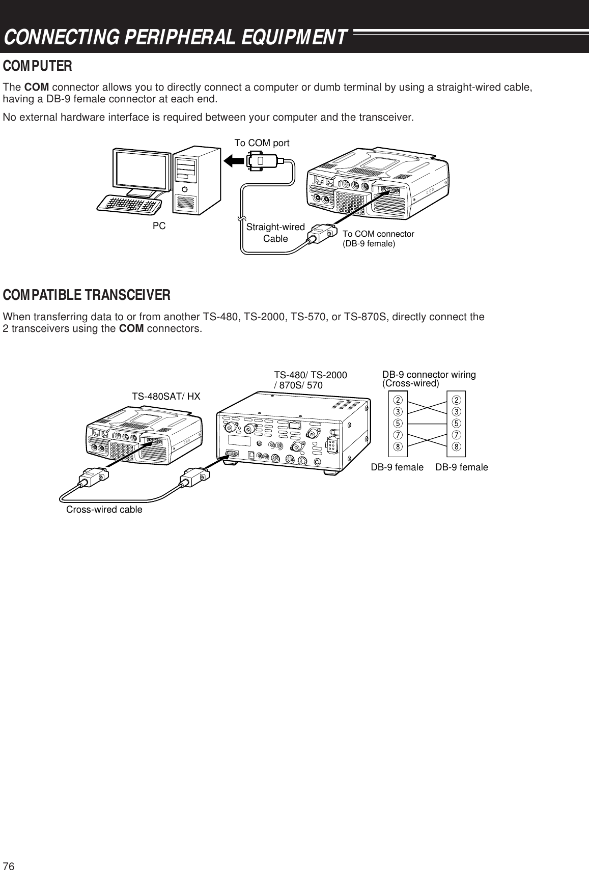
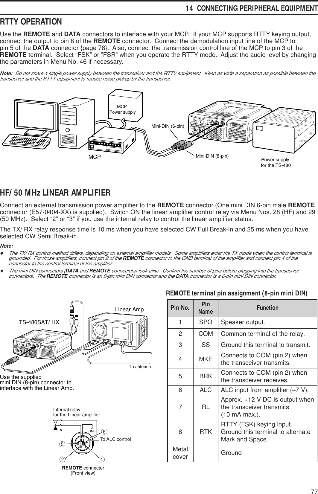
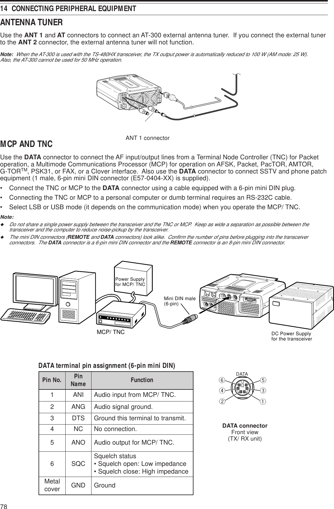
![7914 CONNECTING PERIPHERAL EQUIPMENTDX PACKETCLUSTER TUNEIf you have a TM-D700 transceiver, you can connect the TM-D700 to the TS-480 transceiver to use the DXPacketCluster Tune function. Connect the 2 transceivers with a cross-wired RS-232C cable as shown below.Configure the TM-D700 transceiver to the DX Packet Cluster node frequency.TS-480 transceiver TM-D700 transceiverCross-wired cableRESETGPSCOM DATAMICPANELPADDLE KEYEXT.SP DATA REMOTECOMMIC PANEL1Press [MENU/ F.LOCK] and turn the MULTI control to select Menu No. 56 on the TS-480 transceiver.2Press [ ]/ [ ] to select the same communication baud rate configured on the TM-D700 transceiver.3Tune to the DX Packet Cluster node frequency on the TM-D700 transceiver.4Press [F] (1 s), [TNC] on the TM-D700 transceiver.• “TNC APRS” appears on the TM-D700 transceiver.5Press [F] (1 s), [DX] on the TM-D700 transceiver.6Select a desired DX station data with [ccccc]/ [ddddd] on the TM-D700 transceiver.7Press [MHz] on the TM-D700 transceiver to transfer the frequency data to the TS-480 transceiver.• If the transferred frequency data is available on the TS-480 transceiver, the frequency data will beoverwritten to the current operating frequency. Otherwise, the operating frequency of the TS-480transceiver remains unchanged.For more detailed operation on the DX PacketCluster operation of the TM-D700 transceiver, refer to page 6 of theTM-D700 instruction manual (Specialized Communications).Note: The firmware of the TM-D700 transceiver must be version G2.0 or later to use the PacketCluster function with the TS-480 transceiver.CROSSBAND REPEATERIf you have a TM-D700 transceiver, you can connect the TM-D700 transceiver to the TS-480 transceiver to usethe Crossband repeater function. Connect the 2 transceivers with a mini DIN cable (6-pin) as shown below.TS-480 transceiver TM-D700 transceiverRESETGPSCOM DATAMICPANELPADDLE KEYEXT.SP DATA REMOTECOMMIC PANELAfter connecting the 2 transceivers with the cable, access Menu No. 57 (DTS polarity) on the TS-480 transceiverand select “on”. You will further need to adjust the audio input/ output level of the TS-480 transceiver using MenuNos. 46 and 47.To DATA connector](https://usermanual.wiki/JVC-KENWOOD/33101110.Users-Manual-2/User-Guide-366712-Page-36.png)
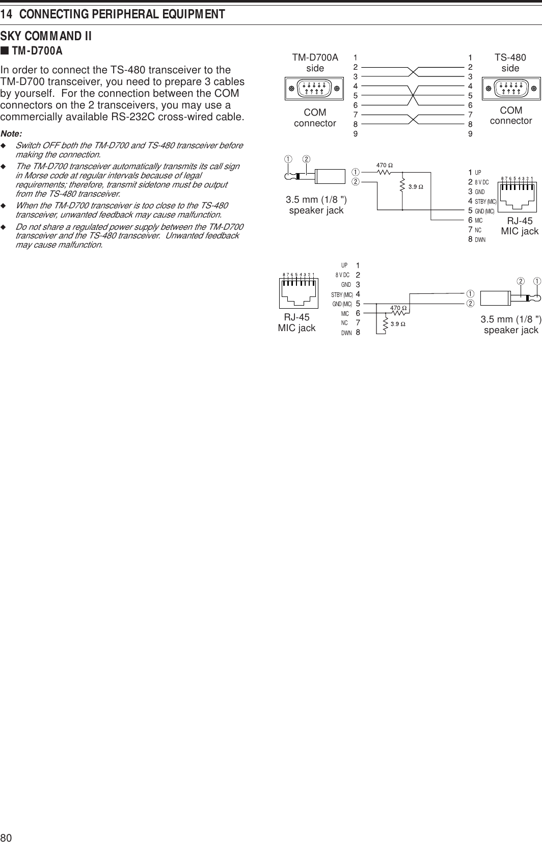
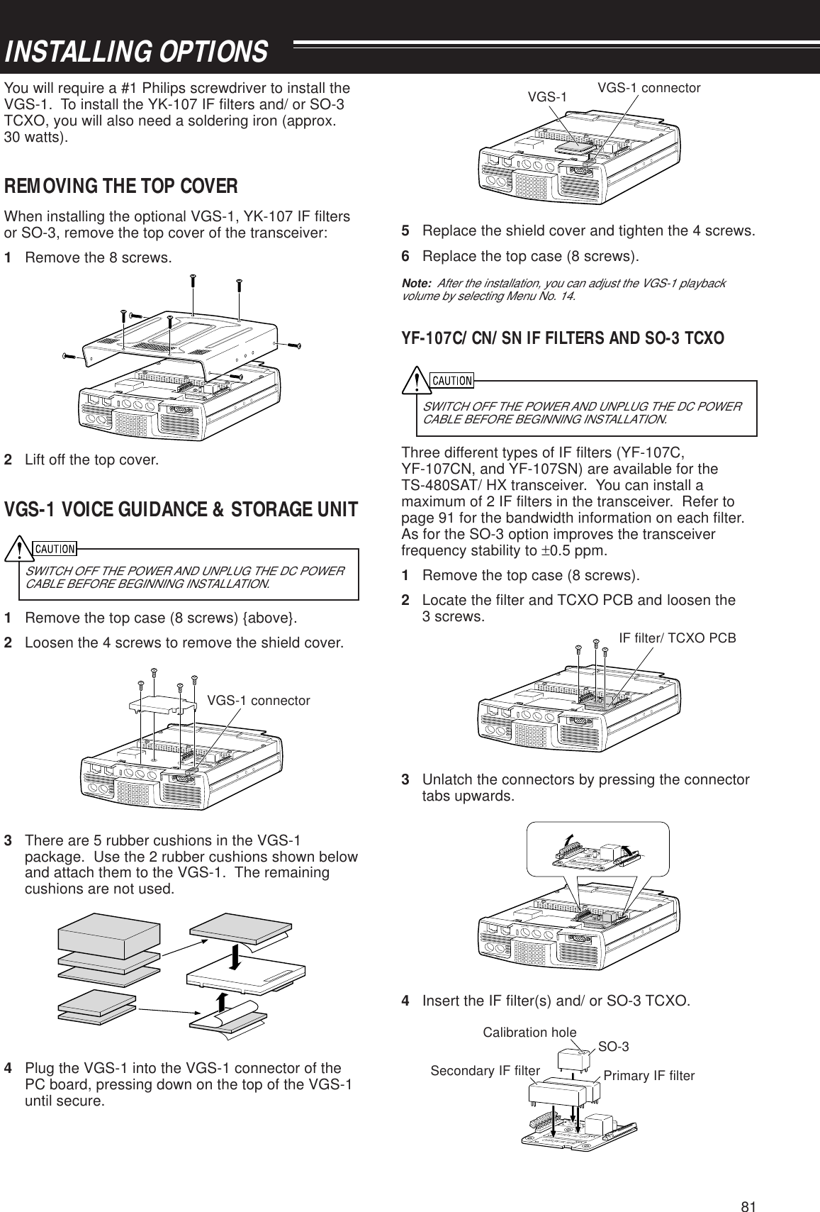
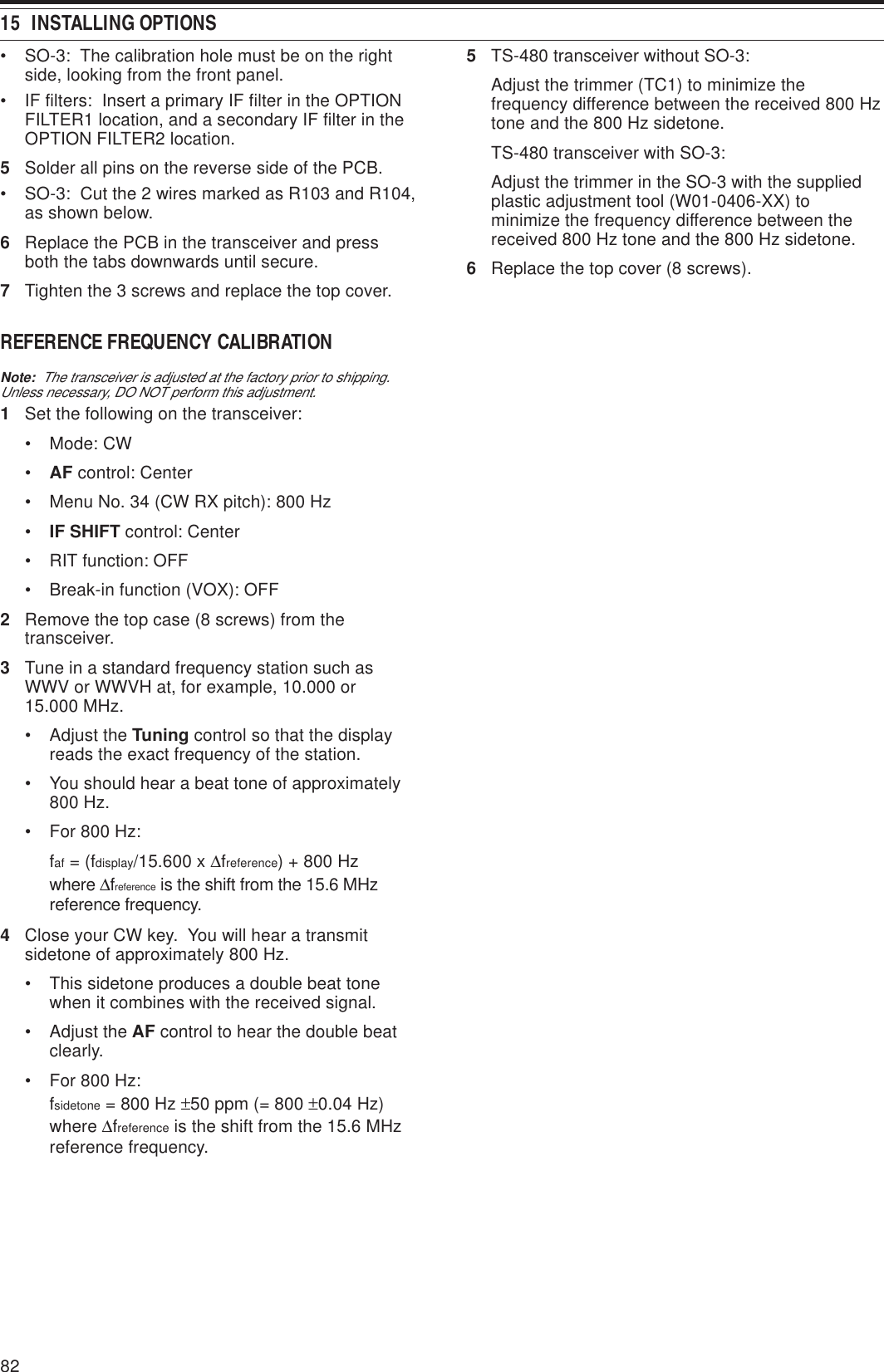
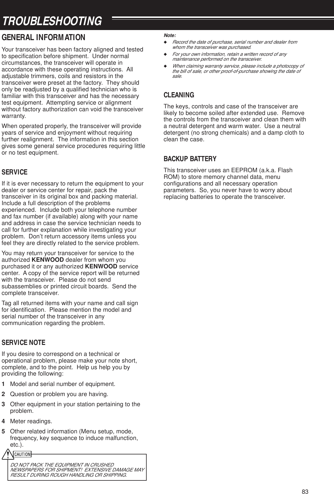
![8416 TROUBLESHOOTINGmelborP esuaCelbaborP noitcAevitcerroC egaP .feRtonlliwreviecsnartehT retfapurewop CDV8.31agnitcennoc dnaylppusrewop gnisserp ][ gnihtoN. ,yalpsidehtnosraeppa siesionreviecerondna .draeh1234.FFOsiylppusrewopCD .elbacrewopytluaFdetcennoctonsielbacrewopehT .yleruces .neposiesufelbacrewoP1234.ylppusrewopCDehtNOhctiwS mrifnoC.elbacrewopehttcepsnI .tcerroceraseitiralop )–(evitagen:kcalB;)+(evitisop:deR CDehtotsnoitcennocehtmrifnoC .eruceseraylppusrewop .esufnwolbehtfoesuacehtrofkooL ynagnitcerrocdnagnitcepsniretfA ehtfoesufwenallatsni,smelborp .gnitardeificepsehtNOgnihctiwsretfA reviecsnarteht,rewop noitcnuftonseod ,elpmaxeroF.yllamron tcerrocnirostigidon ehtnoraeppastigid .yalpsid12V8.31edistuosiegatlovtupniehTCD ±.)CDV8.51ot7.11(%51 sahrossecorporcimehT .denoitcnuflam12ot21aesuroegatlovtupniehttcerroC .yrettabV61 ROSSECORPORCIM“weiveR tahwgnidnatsrednuretfA.”TESER fI.teseRlaitraPaod,tsoleblliwatad .teseRlluFaod,sniamermelborpehtehtNOgnihctiwsretfA eht,reviecsnart otsesuferreviecsnart .timsnart12CDehtfognitartnerrucehT .wolootsiylppusrewop ebtsumseilppusrewopCDowT .XH084-STehtotdetcennoc12sahtahtylppusrewopCDehtesU .gnitartnerruceromroA5.02 ehtotseilppusrewopCD2tcennoC egatlovehT.reviecsnartXH084-ST rewopCD2neewtebecnereffid otV0.1nihtiwebtsumseilppus rewopCDhcaemrifnoc,oslA.timsnart tnerrucrehgihroA5.02asahylppus .gnitarseodreviecsnartehT yltcerrocdnopserton yekgnisserpretfa gninrutrosnoitanibmoc snoitcurtsnirepslortnoc .launamsihtni1234gniebtoneraserudecorP .ylesicerpdewollof sinoitcnufkcoLycneuqerFehT .NO stidnarossecorporcimehT .gnitteserdeenyromemerareviecsnartehtnosyekehT ehtgnitarepoelihwelbaliavanu gninuT .lortnoc1234SNOITNEVNOCGNITIRW“weiveR .”DEWOLLOF sserP )s1(]KCOL.F/UNEM[ hctiwsot.FFOnoitcnufeht ROSSECORPORCIM“weiveR tahwgnidnatsrednuretfA.”TESER fI.teseRlaitraPaod,tsoleblliwatad .teseRlluFaod,sniamermelborpeht ehtgnitarepopotS gninuT ,lortnoc .syeketairporppaehtsserpnehttonnacycneuqerfehT .degnahceb ronoitcnufkcoLycneuqerFehT .NOsinoitcnufllAkcoL sserP )s1(]KCOL.F/UNEM[ ehtnrutot ”“ehT.FFOnoitcnufkcoLycneuqerF .sraeppasidnocisiytilauqoiduaBSS rohgiheht;roopyrev seicneuqerfoiduawol .tnesbaera1234siedomnoitarepognorwehT .reviecerehtrofdetceles yltcerrocnisiretlifPSDFAehT .tes .NOsi2ro1noitcudeResioN.NOsi2ro1lecnaCtaeB1234.edomehtrofBSLroBSUtceleSsserP ]RAN/LIF[ ehtnrutneht ITLUM .htdiwretlifPSDehttsujdaotlortnoc sserP ]RN[ snrutnoitcnufRNehtlitnu.FFO sserP ]T.WC/CB[ noitcnufCBehtlitnu.FFOsnrutTROUBLESHOOTINGThe problems described in this table are commonly encountered operational malfunctions. These types ofdifficulties are usually caused by improper hook-up, accidental incorrect control settings, or operator error due toincomplete programming. These problems are usually not caused by circuit failure. Please review this table, andthe appropriate section(s) of this instruction manual, before assuming your transceiver is defective.Note: Placing a powered portable transceiver near this transceiver may cause noise in the transceiver.](https://usermanual.wiki/JVC-KENWOOD/33101110.Users-Manual-2/User-Guide-366712-Page-41.png)
![8516 TROUBLESHOOTINGmelborP esuaCelbaborP noitcAevitcerroC egaP .feReraslangisoN eviecerrodeviecer smeesytivitisnes .roop123456ehT LQS .esiwkcolcyllufsilortnoc .NOsinoitcnufrotaunettAehTciM ]TTP[ .desserpsi sawhtdiwdnabretlifFIehT .tesyltcerrocnirotcennocannetnagnorwehT .detcelessaw)2TNAro1TNA( .FFOsireifilpmaerpehT123456ehtnruT LQS lortnoc.esiwkcolcretnuocsserP ]2/1TNA/ERP/TTA[ ”TTA“litnu.raeppasid”ERP“dna ciMesaeleR ]TTP[ .GNIGNAHC“,”SRETLIFPSD“weiveR tesdna”HTDIWDNABRETLIFFIEHT .ylgnidroccaslortnoceht sserP )s1(]2/1TNA/ERP/TTA[ ot .rotcennocannetnarehtoehttceles sserP ]2/1TNA/ERP/TTA[ hctiwsot.NOnoitcnufehteraslangisoN eviecerrodeviecer smeesytivitisnes siretem-S;roop .elacsllufgnidaer.woloottessawniagFRehTsserP )s1(]G.FR/5/CIM[ ehtnrutdnaITLUM ehtesaercniotesiwkcolclortnoc.niagFRslangisdevieceR yllatotera .elbigilletninusawedomnoitaludomgnorwehT .detceles sserP ]EDOM[ ro )s1(]EDOM[ tcelesot.edomnoitaludomtcerrocehtlliwnacSyromeM .gninnacstratston 1234ehT LQS testonsawlortnoc.yltcerroc erewslennahcyromem2nahtsseL .dekcolnu erewslennahcyromem2nahtsseL .demmargorp ehT LQS testonsawlortnoc.yltcerroc1234ehttsujdA LQS etanimiletsujotlortnoc .esiondnuorgkcab .slennahcyromem2tsaeltakcolnUyromem2tsaeltaniataderotS .slennahc ehttsujdA LQS .lortnoclliwnacSyromeM ehtfoenonacston eht;slennahcderots silennahcderised .tuodekcolTONlennahceht,detcelesnacSpuorGhtiW .puorgtnereffidanisinacsottnawuoy yromemehtsniatnoctahtpuorgehttceleS .nacsottnawuoylennahclliwnacSmargorP .gninnacstratston eraseicneuqerfdnednatratsehT .lacitnedi .seicneuqerfdnednatratstnereffiderotShsiniftonseodTA .yllufsseccus dnaelbaclaixaocehtfoecnadepmiehT .dehctamtonsawannetna hsinifyllufsseccustonseodgninuT ehthguohtlasnoitidnocnognidneped .1:3nahtrellamssetacidniretemRWSehtrewolotmetsysannetnaehttsujdA .RWSsirenutlanretniehT dessapyb retfayletaidemmi .detratssigninutootsimetsysannetnaehtfoRWSehT .hgih ehtrewolotmetsysannetnaehttsujdA .RWStimsnarttonnacuoY uoyhguohtneve ciMsserp ]TTP[ ro tlusersnoissimsnart .stcatnoconni12345tonsawgulpenohporcimehT CIMehtotniyletelpmocdetresni .rotcennoc .NOsinoitcnuftibihnItimsnarTehT fodaetsnidetcelessawKSFroWC .edomeciova sawhtdiwdnabretlifXTPSDehT .detcelesylreporpni rotcennocannetnagnorwehT .detcelessaw)2TNAro1TNA(12345CIMehterusne,rewopehtFFOnruT ,tinistcejbongierofonsahrotcennoc .ylmrifrotcennocehtnigulpneht .FFOot55.oNuneMegnahC sserP ]EDOM[ .edomeciovatcelesot.02.oNuneMnisgnittesehttsujdAsserP )s1(]2/1TNA/ERP/TTA[ ot .rotcennocannetnarehtoehttceles](https://usermanual.wiki/JVC-KENWOOD/33101110.Users-Manual-2/User-Guide-366712-Page-42.png)

![8816 TROUBLESHOOTINGOPERATION NOTICESNEW AMATEUR RADIO BAND IN THE U.S.The transceiver has been designed and engineeredto avoid possible hardware glitches. However, youmay notice the following symptoms when you operatethe transceiver. These symptoms are notmalfunctions.DC POWER SUPPLYAs stated in the SPECIFICATIONS {page 91}, thistransceiver requires a supplied DC voltage source of13.8 V ±15%. If you find that the transceiver cannotbe switched ON, or that it shuts OFF automatically,the DC voltage may be outside the specified range.In such a case, remove the DC cable from thetransceiver immediately and confirm that the suppliedvoltage is within the specified range.INTERNAL BEATSOn some spots of the transceiver bands, the S-metermoves or you cannot receive any signals. This isinevitable when you use superheterodyne receivers.You may notice the signals on the following spots ofthe bands.1.234.56 MHz, 12.345.67 MHzFAN NOISESWhen the TX/ RX unit is installed in a non-ventilatedarea, the cooling fan(s) may increase in speed andemit a high level of noise for a long time. This isbecause the TX/ RX unit cannot be cooled down withthe regular fan speed. In this case, relocate the TX/RX unit so that air can easily flow through the TX/ RXunit to keep the unit cooled.AGCWhen you turn the AGC function OFF {page 35}, thereceiving audio signals can be distorted. In this case,decrease the RF GAIN, turn the pre-amplifier OFF, orturn the attenuator ON. In general, the RF GAIN isgreatly reduced when the AGC is turned OFF.MICROPROCESSOR RESETIf your transceiver seems to be malfunctioning,resetting the microprocessor default settings mayresolve the problem. There are 2 levels of resettingthe microprocessor of the TS-480 transceiver: PartialReset and Full Reset.INITIAL SETTINGSFor each VFO, the factory defaults for the operatingfrequency and mode are as follows:• VFO A: 14.000.000 MHz/ USB• VFO B: 14.000.000 MHz/ USBThe Memory channels and Quick Memory channelshave no data stored.PARTIAL RESETPerform a Partial Reset if a key or control does notfunction according to the instructions in this manual.The following data is NOT erased by performing aPartial Reset.• Memory channel data• Menu settings• Antenna tuner preset data• ANT 1/ ANT 2 selection data• Frequency and mode data for the Auto Modefunction• Various adjustment setting valuesReset the transceiver by pressing [A/B / M/V]+[ ].• A confirmation message appears when performingthe Partial Reset. Press [A/B / M/V] to proceed.Otherwise, press any other key to cancel thePartial Reset and return to normal operation.• The VFOs reset to the factory default values.FULL RESETPerform a Full Reset if you want to erase all the datain all the memory channels. In addition, this functionresets all the settings that you customized, to thefactory defaults (i.e.- menu settings, antenna tunerpreset data, etc.).Reset the transceiver by pressing[A=B/ SPLIT]+[ ].A confirmation message appears when performingFull Reset. Press [A=B/ SPLIT] to proceed.Otherwise, press any other key to cancel the FullReset and return to normal operation.When you perform the full reset:• All frequencies, modes, memory data, adjustmentvalues, and AT preset data are set to the factorydefault values.](https://usermanual.wiki/JVC-KENWOOD/33101110.Users-Manual-2/User-Guide-366712-Page-45.png)
![8916 TROUBLESHOOTINGDEMONSTRATION MODEThe transceiver can be configured to enter thedemonstration mode for display purposes. To enterthe demonstration mode:1Switch the transceiver OFF.2Press [MENU/ F.LOCK]+[ ] to switch thetransceiver ON.• The display brightness changes, the LED turnsON/ OFF, and alpha-numeric segments turnON/ OFF automatically.• If you operate the transceiver while in thedemonstration mode, the demonstration istemporarily paused. But, if no operation isperformed for more than 10 seconds, thedemonstration starts again.3To exit the demonstration mode, first turn thetransceiver OFF, then press[MENU/ F.LOCK]+[ ] to turn the transceiver ON.Note: You cannot exit the demonstration mode by simply switchingthe transceiver OFF or performing a full reset {page 88}. You mustswitch the transceiver OFF then press [MENU/ F.LOCK]+[ ] toturn the transceiver ON in order to exit the demonstration mode.](https://usermanual.wiki/JVC-KENWOOD/33101110.Users-Manual-2/User-Guide-366712-Page-46.png)