JVC KENWOOD 407110 Scanning Receiver User Manual
JVC KENWOOD Corporation Scanning Receiver
UserManual.wiki
>
JVC KENWOOD
>
407110 User Manual
Users Manual
Navigation menu
Upload a User Manual
Namespaces
Wiki Guide
HTML
PDF
Info
Views
User Manual
Discussion / Help
Navigation

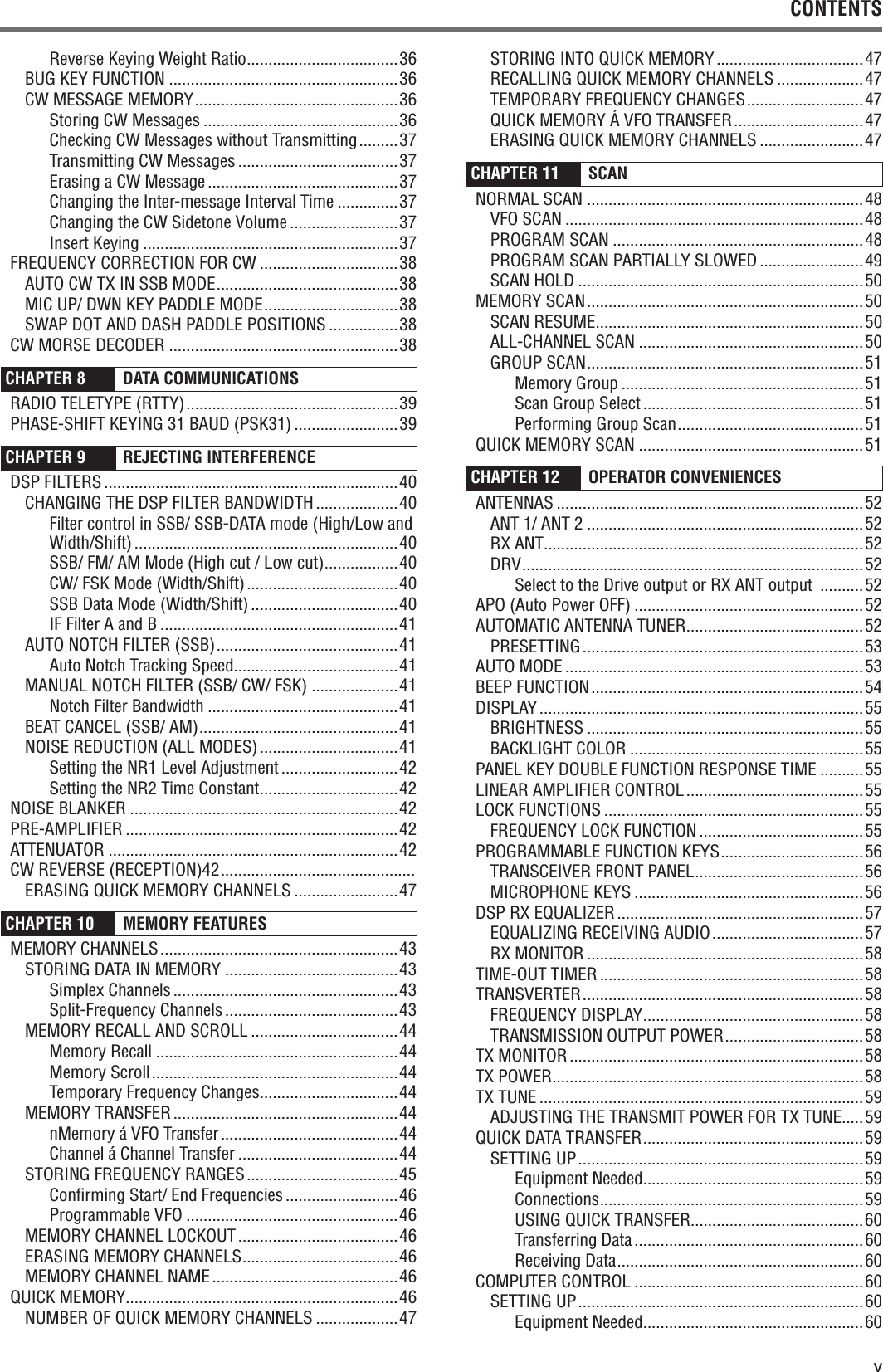
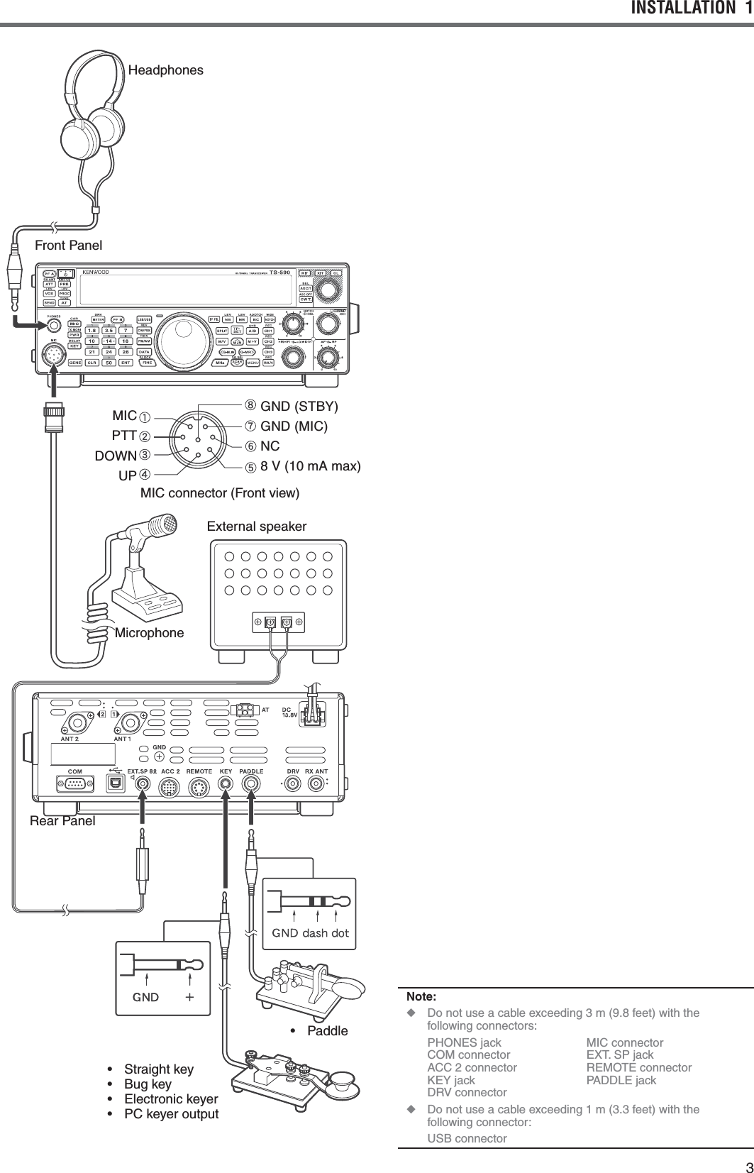
![iiBEFORE STARTINGAmateur radio regulations vary from country to country. Confirm your local amateur radio regulations and requirements before operating the transceiver.$EPENDINGONTHESIZEANDTYPEOFVEHICLETHEmaximum transmission output power for the mobile operation will vary. The maximum transmission output power is usually specified by the car manufacturer to avoid interference with other electric devices used in the vehicle. Consult your car manufacturer and amateur radio equipment dealer for the requirements and installation.MARKET CODESK-type: The AmericasE-type: %UROPEThe market code is shown on the carton box.Refer to the specifications {page } for information on the available operating frequencies.WRITING CONVENTIONS FOLLOWEDThe writing conventions described below have been followed to simplify instructions and avoid unnecessary repetition.Instruction ActionPress [KEY].0RESSANDRELEASE+%9Press Mic [KEY].0RESSANDRELEASE+%9ONthe microphone.Press and hold [KEY].0RESSANDHOLD+%9DOWNfor a moment, then release +%9(OLD[KEY].0RESSANDHOLD+%9DOWNuntil instructed to release +%9Press [KEY] + [].7ITHTHETRANSCEIVERPOWER/&&PRESSANDHOLD+%9then switch the transceiver power ON by pressing [].SUPPLIED ACCESSORIESAfter carefully unpacking the transceiver, identify the ITEMSLISTEDINTHETABLEBELOW7ERECOMMENDYOUkeep the box and packing materials in case you need to repack the transceiver in the future.Accessory Comment QuantityK-type E-typeMicrophone DC power cable Line filter (with retaining band) –Fuse !FOR$#power cable Fuse!FORANexternal antenna tunerDIN plug PIN DIN plug PIN Screw set For bracket Plastic spacer For bracket 4 4Instruction Manual%NGLISH French Spanish – Italian –German –Dutch – Schematic diagram –7ARRANTY#ARD ](https://usermanual.wiki/JVC-KENWOOD/407110/User-Guide-2411097-Page-4.png)
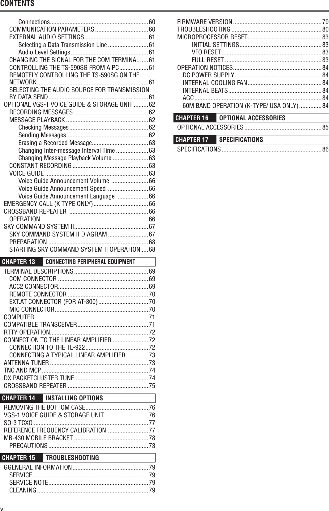
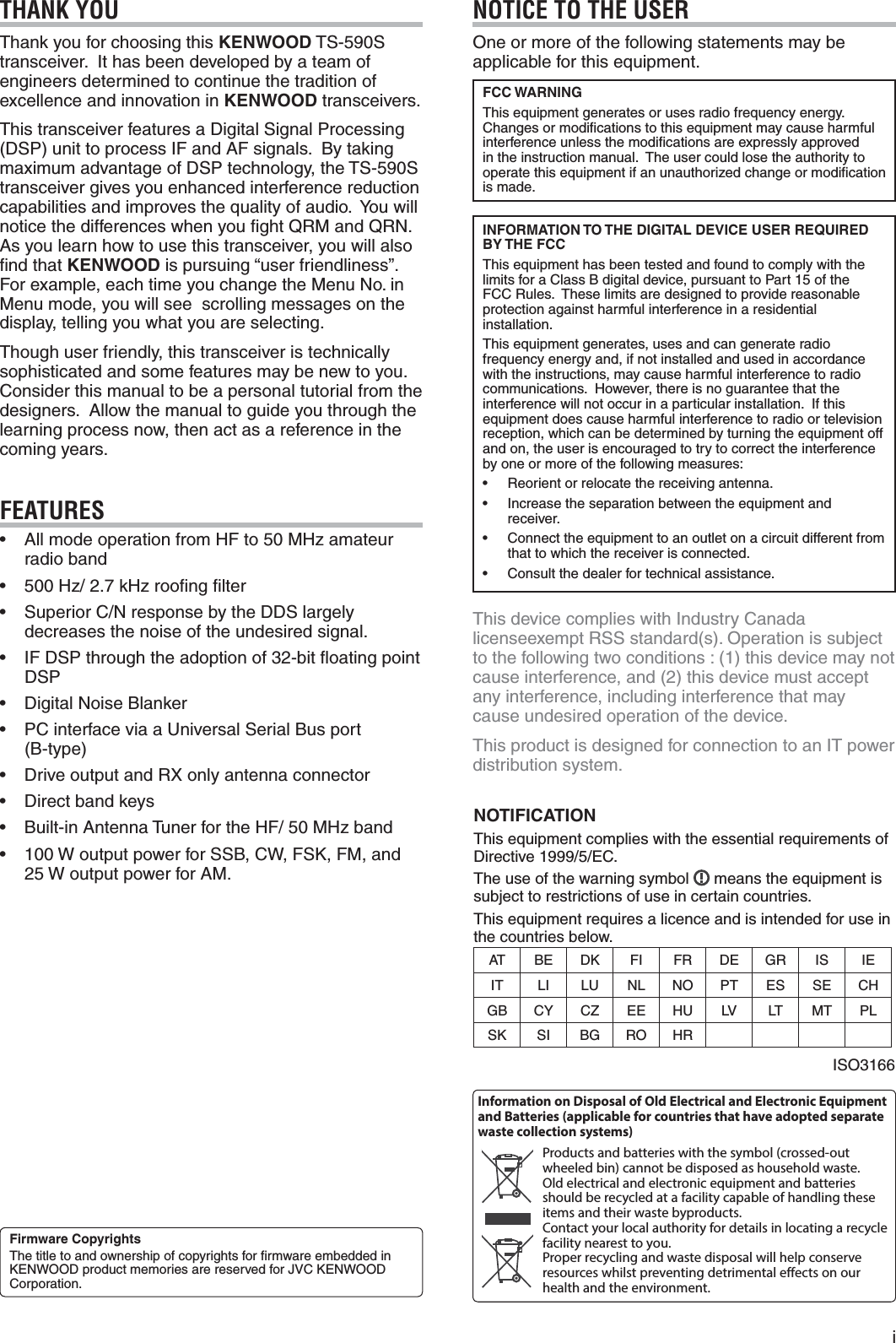
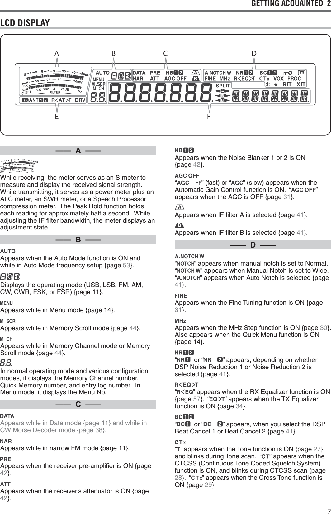
![42 GETTING ACQUAINTEDFRONT PANEL—— C —— [METER (DRV)] Press to switch the meter type {page 12}. Press and hold to turn the Drive Out function ON or OFF {page 50}. [PF B] You can assign a function to this Programmable Function key {page 56}. [MIC (CAR)] Press to adjust the microphone gain {page 13}. While the Speech Processor function is ON, press to adjust the Speech Processor output level {page 33}. Press and hold to adjust the carrier level {page 24}. [PWR (TX MONI)] Press to adjust the transmission output power {pages 13, 58}. Press and hold to turn the transmission signal monitor function ON or OFF {page 58}. [KEY (DELAY)] Press to adjust the internal electronic keyer speed {page 35}. Press and hold to adjust the VOX delay time for voice mode {page 33} or Break-in time (Full Break-in/ Semi Break-in time) for CW mode. [GENE] Press to select the general coverage band memory {page 11}. [1.8 (1)] Press to select the 1.8 MHz band memory {page 11} or enter keypad number 1. [3.5 (2)] Press to select the 3.5 MHz band memory {page 11} or enter keypad number 2. [7 (3)] Press to select the 7 MHz band memory {page 11} or enter keypad number 3. [10 (4)] Press to select the 10 MHz band memory {page 11} or enter keypad number 4. [14 (5)] Press to select the 14 MHz band memory {page 11} or enter keypad number 5. [18 (6)] Press to select the 18 MHz band memory {page 11} or enter keypad number 6.—— A —— [ ] Press and hold to switch the transceiver power ON and OFF {page 10}. [PF A] You can assign a function to this Programmable Function key {page 56}. [ATT (RX ANT)] Press to turn the receiver attenuator ON or OFF {page 42}. Press and hold to enable or disable the RX-ANT terminal {page 52}. [PRE (ANT 1/2)] Press to turn the pre-amplifier ON or OFF {page 40}. Press and hold to select either ANT 1 or ANT 2 {page 52}. [VOX (LEV)] In voice mode, press to turn the VOX (Voice-Operated Transmit) function ON or OFF {page 32}. In CW mode, press to turn the Break-in function ON or OFF {page 35}. Press and hold to adjust the microphone input gain for VOX operation. [PROC (LEV)] Press to turn the Speech Processor ON or OFF {page 33}. Press and hold to adjust the Speech Processor input level. [SEND] Press to turn transmission ON or OFF. [AT (TUNE)] Press to turn the internal antenna tuner ON or OFF {page 50}. Press and hold to start tuning the automatic antenna tuner.—— B ——PHONES jack Mate with a 6.3 mm (1/4") diameter, 2-conductor (mono) or 3-conductor (stereo) plug for connecting a set of headphones {page 2}.MIC connector Connect a microphone to this connector {page 2}.ABCDFEGH](https://usermanual.wiki/JVC-KENWOOD/407110/User-Guide-2411097-Page-12.png)
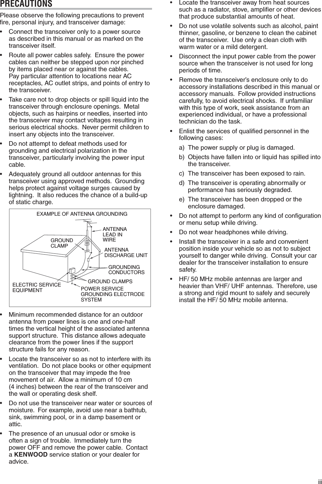
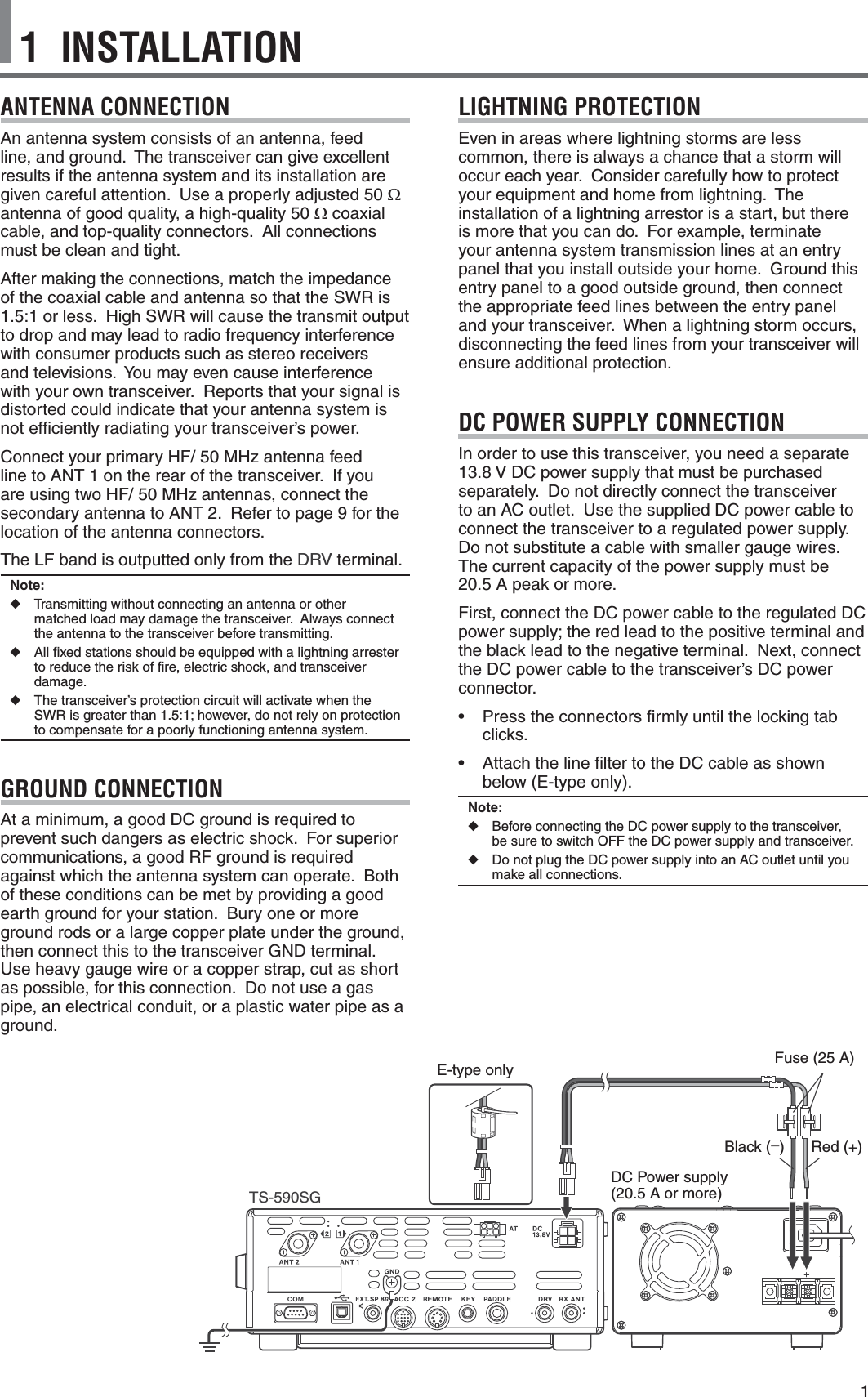
![5GETTING ACQUAINTED 2 [21 (7)] Press to select the 21 MHz band memory {page 11} or enter keypad number 7. [24 (8)] Press to select the 24 MHz band memory {page 11} or enter keypad number 8. [28 (9)] Press to select the 28 MHz band memory {page 11} or enter keypad number 9. [50 (0)] Press to select the 50 MHz band memory {page 11} or enter keypad number 0. [CLR] Press to exit from, abort, or reset various functions. Press and hold to clear a memory channel {page 46}. [ENT] Press to enter your desired frequency using the 10-key keypad {page 30}.—— D —— [LSB/USB] Press to select LSB or USB mode {page 11}. [CW/FSK (REV)] Press to select CW or FSK mode {page 11}. Press and hold to select a sideband (CW/ CW-R or FSK/ FSK-R). [FM/AM (FM-N)] Press to select FM or AM mode {page 11}. Press and hold to select Narrow FM mode. [DATA] Press to select a Data mode (LSB/ LSB-DATA, USB/ USB-DATA, FM/ FM-DATA, or AM-DATA) {page 11}. [FINE (F.LOCK)] Press to activate the Fine tuning function to allow more precise tuning {page 31}. Press and hold to activate the Frequency Lock function {page 55}.—— E ——Central (Tuning) control Turn to select the desired frequency {page 12}. Use the convenient finger-tip cavity for continuous tuning. Slide the lever underneath the Tuning control to the left or right to adjust the torque level of the control. Left makes the control light and right makes it heavy.light heavyTX-RX LED Lights red while transmitting and green when the squelch opens while receiving.—— F —— [IF FIL] Press to toggle between IF Filter A and IF Filter B {page 41}. You can adjust the filter bandwidth using the LO/WIDTH and HI/SHIFT controls. Press and hold [IF FIL] to momentarily display each setting value of the current DSP filter DSP filter bandwidth {page 38}. [NB (LEV)] Press to cycle through Noise Blanker 1, Noise Blanker 2, and OFF. Press and hold to adjust the Noise Blanker level {page 42}. [NR (LEV)] Press to cycle through the DSP Noise Reduction types: NR1, NR2, or OFF {page 41}. When the Noise Reduction function is turned ON, press and hold to change the parameters of the Noise Reduction function {page 40}. [BC (A.NOTCH)] Press to select the DSP Beat Cancel function, BC1 (Beat Cancel 1), BC2 (Beat Cancel 2) or OFF {page 41}. Press and hold to toggle the Auto Notch Filter ON and OFF {page 41}. [NOTCH (WIDE)] Press to toggle the IF Notch Filter ON or OFF {page 41}. Press and hold to set up the IF Notch bandwidth {page 41}. [SPLIT] Press to enter split-frequency operation, allowing you to use different transmission and reception frequencies {page 25}. [TF-SET] During split-frequency operation, press to monitor or change your transmit frequency {page 26}. [A/B (A=B)] Press to select either VFO A or VFO B {page 10}. Press and hold to duplicate the data in the current VFO to the other VFO {page 27}. While in Menu mode, press to select Menu A or Menu B. While in Program Memory Channel mode, press to recall the start or end frequency. [M/V] Press to toggle between Memory and VFO modes. [M.IN] Press to enter Memory Scroll mode and to store data to a Memory channel {page 43}. [M>V] Press to transfer the current Memory Channel contents to the VFO. [Q-M.IN] Press to store data to the Quick Memory {page 46}. [Q-MR] Press to recall data from the Quick Memory {page 47}, while in VFO mode. Press to enter Memory Name Edit mode, while in Memory Channel mode {page 46}. [MHz] Press to turn the MHz Up/ Down function ON or OFF. The MHz digit increases or decreases when you turn the MULTI/CH control. In Menu mode, press to turn the Quick Menu ON or OFF {page 14}. [SCAN (SG.SEL)] Press to start or stop the Scan function {page 48}. Press and hold to select a Scan group {page 51}. [MENU] Press to enter Menu mode {page 14}.](https://usermanual.wiki/JVC-KENWOOD/407110/User-Guide-2411097-Page-13.png)
![62 GETTING ACQUAINTED [CH1 (REC)] Press to play back a CW {page 37} or voice message (requires VGS-1 option) {page 62}. Press and hold to record a CW {page 36} or voice message (requires VGS-1 option) {page 62}. [CH2 (REC)] Press to play back a CW {page 37} or voice message (requires VGS-1 option) {page 62}. Press and hold to record a CW {page 36} or voice message (requires VGS-1 option) {page 62}. [CH3 (REC)] Press to play back a CW {page 37} or voice message (requires VGS-1 option) {page 62}. Press and hold to record a CW {page 36} or voice message (requires VGS-1 option) {page 62}. [RX/4 (REC)] Press to play back a CW {page 37} or voice message (requires VGS-1 option) {page 62}, or the constantly recorded signal (requires VGS-1 option) {page 63}. Press and hold to activate the constant recorder (requires VGS-1 option) {page 63}.—— G —— [AGC/T (SEL)] Press to toggle the fast or slow response time for the Automatic Gain Control (AGC) {page 31}. In FM mode, press to cycle through the Tone settings: Tone, CTCSS, CTCSSx, or OFF {page 28}. When Tone is activated in FM mode, press and hold to select a Tone frequency {page 28}. When CTCSS is activated in FM mode, press and hold to select a CTCSS frequency {page 29}. [CW T. (AGC OFF)] Press to start CW auto tuning {page 23}. Press and hold to turn AGC OFF {page 31}. [RIT] Press to turn the RIT (Receive Incremental Tuning) function ON or OFF {page 31}.You can assign a function to this Programmable Function key {page 56}. [XIT] Press to turn the XIT (Transmit Incremental Tuning) function ON or OFF {page 33}.You can assign a function to this Programmable Function key {page 56}. [CL] Press to clear the RIT/ XIT frequency to zero {pages 31, 33}.You can assign a function to this Programmable Function key {page 56}.RIT/ XIT control When the RIT/ XIT function is ON, turn to adjust the offset frequency. The RIT/ XIT offset frequency appears on the sub-display {pages 29, 31}. While scanning, turn to adjust the scan speed.—— H ——SQL control Turn to select the desired squelch level {page 12}.NOTCH control Turn to select the desired Notch frequency {page 41}.MULTI/CH control In VFO mode, rotate to step the operating frequency up or down {page 30}. In Memory Channel mode, rotate to select a Memory Channel {page 43}. Also, used for selecting Menu numbers when accessing the Menu mode {page 14} and for various configurations. The MULTI/CH LED lights when the MULTI/CH control is not being used to adjust the step frequency.You can assign a function to this Programmable Function key {page 56}.HI/SHIFT control Rotate to adjust the DSP filter bandwidth (high-cut) or to adjust the DSP filter bandwidth (filter band shift) {page 40}.LO/WIDTH control Rotate to adjust the DSP filter bandwidth (high-cut or shift) {page 40}.AF control Turn to adjust the AF gain level {page 10}.RF control Turn to adjust the RF gain level {page 10}.ABCDFEGH](https://usermanual.wiki/JVC-KENWOOD/407110/User-Guide-2411097-Page-14.png)
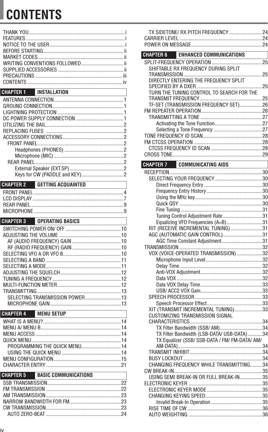
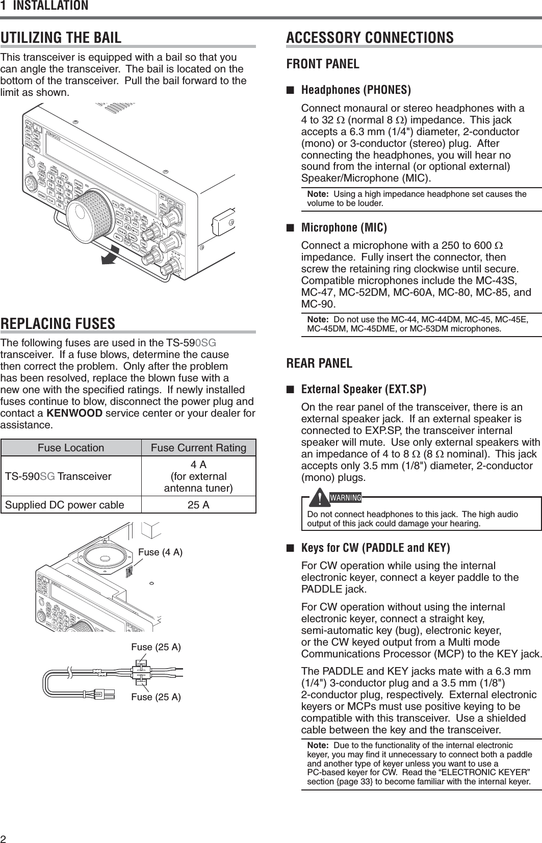
![9GETTING ACQUAINTED 2 ANT 1 and ANT 2 connectors Connect your primary HF/ 50 MHz antenna to ANT 1 connector. If you are using 2 antennas for the HF/ 50 MHz band, connect the secondary antenna to the ANT 2 connector {page 1}.GND post Connect a heavy gauge wire or copper strap between the ground post and the nearest earth ground {page 1}.AT connector Mates with the connector from the cable supplied with the AT-300 external antenna tuner {pages 70, 73}. Refer to the instruction manual supplied with the tuner for more information.DC 13.8 V connector Connect a regulated 13.8 V DC power source to this connector {page 1}. Use the DC cable supplied with the transceiver.COM connector Mates with a DB-9 female connector for connecting a computer or compatible transceiver {pages 60, 69}. Also used with the Quick Data Transfer function {page 59} and DX PacketCluster Tune function {page 67}. (USB) connector Mates with a USB connector for connecting a computer via one of its USB ports {pages 60}.EXT.SP 8: jack Mate with a 3.5 mm (1/8"), 2-conductor (mono) plug for connecting an external speaker {page 2}.ACC 2 connector Mates with a 13-pin male DIN connector for connecting various accessory equipment, such as an external TNC/ MCP or a RTTY terminal {page 69}.REMOTE connector Mates with a 7-pin male DIN connector for connecting an HF/ 50 MHz linear amplifier {page 65, 68}.KEY and PADDLE jacks The KEY jack mates with a 3.5 mm (1/8") 2-conductor plug for connecting an external key for CW operation. The PADDLE jack mates with a 6.3 mm (1/4") 3-conductor plug for connecting a keyer paddle to the internal electronic keyer. Refer to “Keys for CW (PADDLE and KEY)” {page 2} before using these jacks.REAR PANELDRV connector Connect a drive device to this RCA connector {page 52}.RX ANT connector Connect a separate receive-only antenna for HF low bands to this RCA connector {page 52}.MICROPHONEPTT (Push-to-Talk) switch The transceiver is placed in Transmission mode when this non-locking switch is held down. Releasing the switch returns the transceiver to Reception mode. / Mic [UP]/ [DWN] Use these keys to step the VFO frequency, Memory Channels, or Menu selections up and down. Press and hold these keys to continuously change the settings. You can also change the operational function of these keys {page 56}](https://usermanual.wiki/JVC-KENWOOD/407110/User-Guide-2411097-Page-17.png)
![103 OPERATING BASICSSWITCHING POWER ON/ OFF1 Switch the DC power supply ON.2 Press [] to switch the transceiver ON.s )FYOUHOLDTHEPOWERSWITCHFORMORETHANAPPROXIMATELYSECONDSTHETRANSCEIVERWILLswitch back OFF.s 5PONPOWERUPh(%,,/vAPPEARSONTHEMAINDISPLAYFOLLOWEDBYTHECURRENTFREQUENCYANDOTHERINDICATORS3 4OSWITCHTHETRANSCEIVER/&&PRESS[ ] again.4 Switch the DC power supply OFF.s 9OUMAYSKIPSTEP3!FTERSWITCHINGTHETRANSCEIVER/.YOUCANSWITCHIT/&&OR/.USINGONLYTHEPOWERSWITCHOFTHE$#POWERSUPPLY4HETRANSCEIVERREMEMBERSTHEPOWERswitch position when the DC power source is SWITCHED/&&ADJUSTING THE VOLUMEAF (AUDIO FREQUENCY) GAINTurn the AFCONTROLCLOCKWISETOINCREASETHEAUDIOLEVELANDCOUNTERCLOCKWISETODECREASEITNote:4HEPOSITIONOFTHEAFCONTROLDOESNOTAFFECTTHEVOLUMEOFBEEPSCAUSEDBYPRESSINGKEYSNORTHE#748SIDETONE4HEAUDIOLEVELFOR$IGITALMODEOPERATIONISALSOINDEPENDENTOFTHEAF control setting.RF (RADIO FREQUENCY) GAIN4HE2&GAINISNORMALLYCONlGUREDTOTHEMAXIMUMLEVELREGARDLESSOFTHEOPERATINGMODES4HETRANSCEIVERHASBEENCONlGUREDTOTHEMAXIMUMLEVELATTHEFACTORY(OWEVERYOUMAYDECREASETHERF gain slightly when you have trouble hearing the DESIREDSIGNALDUETOEXCESSIVEATMOSPHERICNOISEORINTERFERENCEFROMOTHERSTATIONS&IRSTTAKENOTEOFTHEPEAK3METERREADINGOFTHEDESIREDSIGNAL4HENTURNTHERF control COUNTERCLOCKWISEUNTILTHE3METERREADSTHEPEAKVALUETHATYOUNOTEDs 3IGNALSTHATAREWEAKERTHANTHISLEVELWILLBEATTENUATEDANDRECEPTIONOFTHESTATIONWILLBECOMEeasier.$EPENDINGONTHETYPEANDGAINOFYOURANTENNAANDTHECONDITIONOFTHEBANDADJUSTTHE2&GAIN7HENUSING&-MODEALWAYSADJUSTTHE2&GAINTOTHEMAXIMUMLEVELSELECTING VFO A OR VFO B4WO6&/SAREAVAILABLEFORCONTROLLINGTHEFREQUENCYONTHETRANSCEIVER%ACH6&/6&/!AND6&/"WORKSINDEPENDENTLYSOTHATADIFFERENTFREQUENCYANDMODECANBESELECTED&OREXAMPLEWHEN30,)4OPERATIONISACTIVATED6&/!ISUSEDFORRECEPTIONAND6&/"ISUSEDFORTRANSMISSION4HEOPPOSITECOMBINATIONISALSOPOSSIBLEPress [A/B (A=B)] TOTOGGLEBETWEEN6&/!AND"](https://usermanual.wiki/JVC-KENWOOD/407110/User-Guide-2411097-Page-18.png)
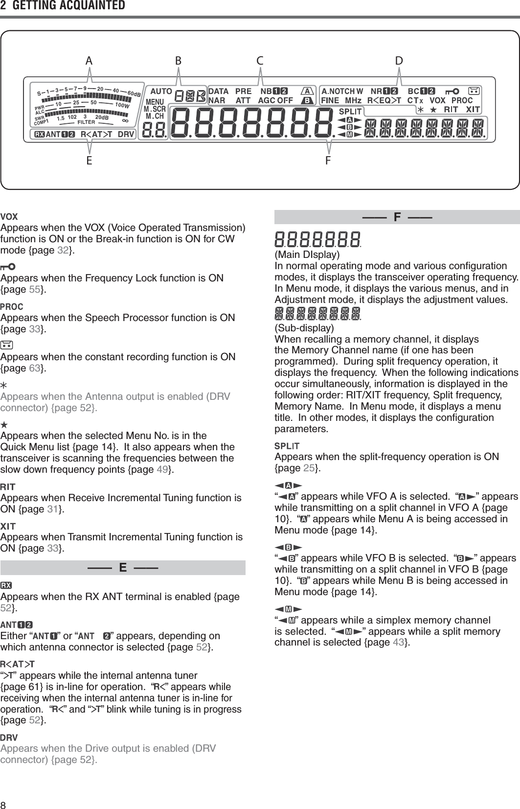
![113 OPERATING BASICSSELECTING A BANDPress [1.8 (1)] ~ [50 (0)] or [GENE] to select your DESIREDBANDs 0RESSEACHKEYTOCYCLETHROUGHTHEDEFAULTsettings as shown in the table below.s %ACHSETTINGCANBEMODIlEDWITHYOURPERSONALPREFERENCEFORFREQUENCYANDMODE!FTERMODIFYINGTHESETTINGPRESSINGTHEKEYAGAINWILLsave that setting.KeyTypeFrequency Range (MHz)Default Setting (MHz)/ Mode123[1.8 (1)]K^1.8/ #7#71.84/ #7%#71.84/ #71.81/ #7[3.5 (2)]K^ ,3",3",3"%,3"[7 (3)]K^ ,3",3",3"%,3",3"[10 (4)]All ^ 10.1/ #7#710.14/ #7[14 (5)]All^14.0/ 53"14.1/ 53"53"[18 (6)]All ^18.068/ 53"18.11/ 53"53"[21 (7)]All^53"53"53"[24 (8)]All ^53"53"53"[28 (9)]All ^ 53"53"FM[50 (0)]K^ 53"53" FM%53"[GENE]K^#753"53"%53"SELECTING A MODE0RESSONEOFTHEFOLLOWINGKEYSTOSELECTYOURDESIREDMODESET[LSB/USB][CW/FSK (REV)]OR[FM/AM (FM-N)].[LSB/USB] 0RESSTOSELECT,3"OR53"MODE0RESSAGAINTOTOGGLEBETWEEN,3"AND53"MODE 7HILEIN,3"MODEPRESS[DATA] to toggle between ,3"AND,3"$!4!MODE,IKEWISEWHILEIN53"MODEPRESS[DATA]TOTOGGLEBETWEEN53"AND53"$!4!MODE !DDITIONALLYWHILEIN,3"$!4!OR53"$!4!MODEyou can press [LSB/USB]TOTOGGLEBETWEEN,3"$!4!AND53"$!4!MODE[CW/FSK (REV)] 0RESSTOSELECT#7OR&3+MODE0RESSAGAINTOTOGGLEBETWEEN#7AND&3+MODE 7HILEIN#7MODEPRESSANDHOLD[CW/FSK (REV)] TOTOGGLEBETWEEN#7AND#72MODE,IKEWISEWHILEIN&3+MODEPRESSANDHOLD[CW/FSK (REV] to TOGGLEBETWEEN&3+AND&3+2MODE !DDITIONALLYWHILEIN#72OR&3+2MODEYOUCANpress [CW/FSK (REV)]TOTOGGLEBETWEEN#72AND&3+2MODE[FM/AM (FM-N)] 0RESSTOSELECT&-OR!-MODE0RESSAGAINTOTOGGLEBETWEEN&-AND!-MODE 7HILEIN&-MODEPRESSANDHOLD[FM/AM (FM-N)] TOTOGGLEBETWEEN&-AND&-.!2MODEORPRESS[DATA]TOTOGGLEBETWEEN&-AND&-$!4!MODE !DDITIONALLYWHILEIN&-.!2MODEPRESS[DATA] to TOGGLEBETWEEN&-.!2AND&-.!2$!4!MODEANDWHILEIN&-$!4!MODEPRESSANDHOLD[FM/AM (FM-N)]TOTOGGLEBETWEEN&-$!4!AND&-.!2$!4!MODE7HILEIN!-MODEPRESS[DATA] to toggle between !-AND!-$!4!MODE Access Menu No. then press [M.IN]TOSELECThONvTOTURNTHE!UTO-ODESELECTION/.7HENITIS/. hvAPPEARS!SADEFAULTIFYOUCHANGETHEFREQUENCYABOVEORBELOW-(ZTHETRANSCEIVERAUTOMATICALLYSWITCHESMODES,3"FORFREQUENCIESUNDER-(ZAND53"FORFREQUENCIES-(ZANDOVER9OUCANFURTHERADDTHEFREQUENCYBORDERSTOTHE!UTO-ODESELECTION[PAGE}.Note:4HELASTUSEDMODEISSTOREDPEREACHBANDKEY](https://usermanual.wiki/JVC-KENWOOD/407110/User-Guide-2411097-Page-19.png)
![3 OPERATING BASICSMULTI-FUNCTION METER4HEMULTIFUNCTIONMETERMEASURESTHEPARAMETERSINTHETABLEBELOW4HE3METERAND&),4%2SCALESAPPEARSWHENTHETRANSCEIVERISINRECEIVEMODEANDTHE072METERAPPEARSWHENITISINTRANSMITMODE%ACHPRESSOF [METER (DRV)] cycles between the !,##/-0AND372METERS0EAKREADINGSFORTHE3METER!,#372#/-0AND072FUNCTIONSAREHELDMOMENTARILYALCCOMPSWRMeter Name Parameters MeasuredS3TRENGTHOFRECEIVEDSIGNALS072 4RANSMISSIONOUTPUTPOWER!,# !UTOMATICLEVELCONTROLSTATUS372 !NTENNASYSTEMSTANDINGWAVERATIOCOMP3PEECHCOMPRESSIONLEVELWHEN using the Speech Processor [PAGE}&),4%2 )&lLTERWIDTH[PAGE40}Note:◆ 4HE#/-0METERFUNCTIONSONLYWHENTHE3PEECH0ROCESSORIS/.FOR33"&-OR!-MODE◆ 0EAK(OLDREADINGSCANNOTBEDEACTIVATED◆ 4HE3METERRESPONDSDIFFERENTLYIN&-MODECOMPAREDTOOTHERMODES4HISISNOTAMALFUNCTION◆ 7HENYOUTURN/&&THE3PEECH0ROCESSORWHILEUSINGTHE#/-0METERTHE#/-0METERCHANGESTOTHE!,#METER7HENYOUTURN/.THE3PEECH0ROCESSORAGAINTHE!,#METERRETURNSTOTHE#/-0METERADJUSTING THE SQUELCH4HEPURPOSEOFTHE3QUELCHISTOMUTETHESPEAKERWHENNOSIGNALSAREPRESENT7ITHTHESQUELCHLEVELCORRECTLYSETYOUWILLHEARSOUNDONLYWHILEACTUALLYRECEIVINGSIGNALS4HEHIGHERTHESELECTEDSQUELCHLEVELTHESTRONGERTHESIGNALSMUSTBETORECEIVE4HEAPPROPRIATESQUELCHLEVELDEPENDSONTHEAMBIENT2&NOISECONDITIONSTurn the SQL control when there are no signals PRESENTTOSELECTTHESQUELCHLEVELATWHICHTHEBACKGROUNDNOISEISJUSTELIMINATEDTHEGREEN4828 ,%$WILLTURNOFF-ANYHAMOPERATORSPREFERLEAVINGthe SQLCONTROLFULLYCOUNTERCLOCKWISEUNLESSOPERATINGONAFULLCARRIERMODESUCHAS&-4HESQUELCHLEVELFORTHETRANSCEIVERISPRESETATTHEFACTORYTOAPPROXIMATELYTHEOCLOCKPOSITIONFOR&-ANDOCLOCKFOR33"AND!-TUNING A FREQUENCYTurn the Tuning control clockwise or press Mic [UP TOINCREASETHEFREQUENCY4URNTHETuning control counterclockwise or press Mic [DWN]TODECREASETHEFREQUENCY9OUMAYPREFERDIRECTLYENTERINGAFREQUENCYUSINGTHENUMERICKEYPADIFTHEDESIREDFREQUENCYISFARFROMTHECURRENTFREQUENCY0RESS [ENT] then press THENUMERICKEYSASNECESSARY&ORDETAILSREFERTOh$IRECT&REQUENCY%NTRYv[PAGE}.](https://usermanual.wiki/JVC-KENWOOD/407110/User-Guide-2411097-Page-20.png)
![OPERATING BASICS 3TRANSMITTING&ORVOICECOMMUNICATIONSPRESSANDHOLD-IC[PTT] ANDSPEAKINTOTHEMICROPHONEINYOURNORMALVOICE7HENYOUlNISHSPEAKINGRELEASE-IC[PTT] to receive.4OTRANSMIT#7PRESS[VOX (REV)]TOTURNTHE"REAKINFUNCTION/.h vAPPEARS#LOSETHEKEYORKEYERPADDLE#ONNECTAKEYORKEYERPADDLE[PAGE]THENSELECT#7USING [CW/FSK (REV)].&ORADETAILEDEXPLANATIONONTRANSMITTINGREFERTOh"!3)##/--5.)#!4)/.3vBEGINNINGONPAGE.SELECTING TRANSMISSION POWER)TISWISETOSELECTALOWERTRANSMISSIONPOWERIFCOMMUNICATIONISSTILLRELIABLE4HISLOWERSTHERISKOFINTERFERINGWITHOTHERSONTHEBAND7HENOPERATINGFROMBATTERYPOWERSELECTINGALOWERTRANSMISSIONPOWERALLOWSYOUMOREOPERATINGTIMEBEFORErecharging is necessary. This transceiver allows YOUTOCHANGETHETRANSMISSIONPOWEREVENWHILETRANSMITTING1 Press [PWR (TX MONI)].s 4HECURRENTTRANSMISSIONPOWERAPPEARS2 Turn the MULTI/CH control counterclockwise to REDUCETHEPOWERORCLOCKWISETOINCREASETHEpower.3 Press [PWR (TX MONI)] or [CLR]TOCOMPLETETHEsetting.Note: 9OUCANACCESS-ENU.OANDSELECThONvTOCHANGETHESTEPSIZEFROM7TO7[PAGE}.MICROPHONE GAIN4HEMICROPHONEGAINMUSTBEADJUSTEDWHEN33" OR!-MODEISSELECTEDWITHOUTUSINGTHESPEECHPROCESSOR[PAGES}.1 Press [MIC (CAR)].s 4HECURRENTMICROPHONEGAINLEVELAPPEARS4HERANGEISFROMTOWITHADEFAULTOF2 0RESSANDHOLD-IC[PTT].s 4HE4828,%$LIGHTSRED3 33"7HILESPEAKINGINTOTHEMICROPHONEADJUSTthe MULTI/CHCONTROLSOTHATTHE!,#METERREmECTSYOURVOICELEVELBUTDOESNOTEXCEEDTHE!,#LIMIT !-7HILESPEAKINGINTOTHEMICROPHONEADJUSTthe MULTI/CHCONTROLSOTHATTHEPOWERMETERslightly reflects your voice level. &-!CCESS-ENU.OANDSELECThv.ORMALhv-EDIUMORhv(IGHFORTHEMICROPHONEGAINIFNECESSARY[PAGE}.4 Release Mic [PTT] to receive.s 4HE4828,%$LIGHTSGREENORTURNSOFFDEPENDINGONTHESQL control setting.5 Press [MIC (CAR)] or [CLR] to exit the Microphone GAINADJUSTMENTNote: 7HENUSINGTHE-#MICROPHONEIN&-MODESELECThv(IGHFORTHEMICROPHONEGAIN4HEMICROPHONESENSITIVITYISLOWIN&-MODE4HISMAYCAUSEINSUFlCIENTMODULATION&OROTHERMICROPHONESSELECTEITHERhv.ORMALORhv-EDIUM](https://usermanual.wiki/JVC-KENWOOD/407110/User-Guide-2411097-Page-21.png)
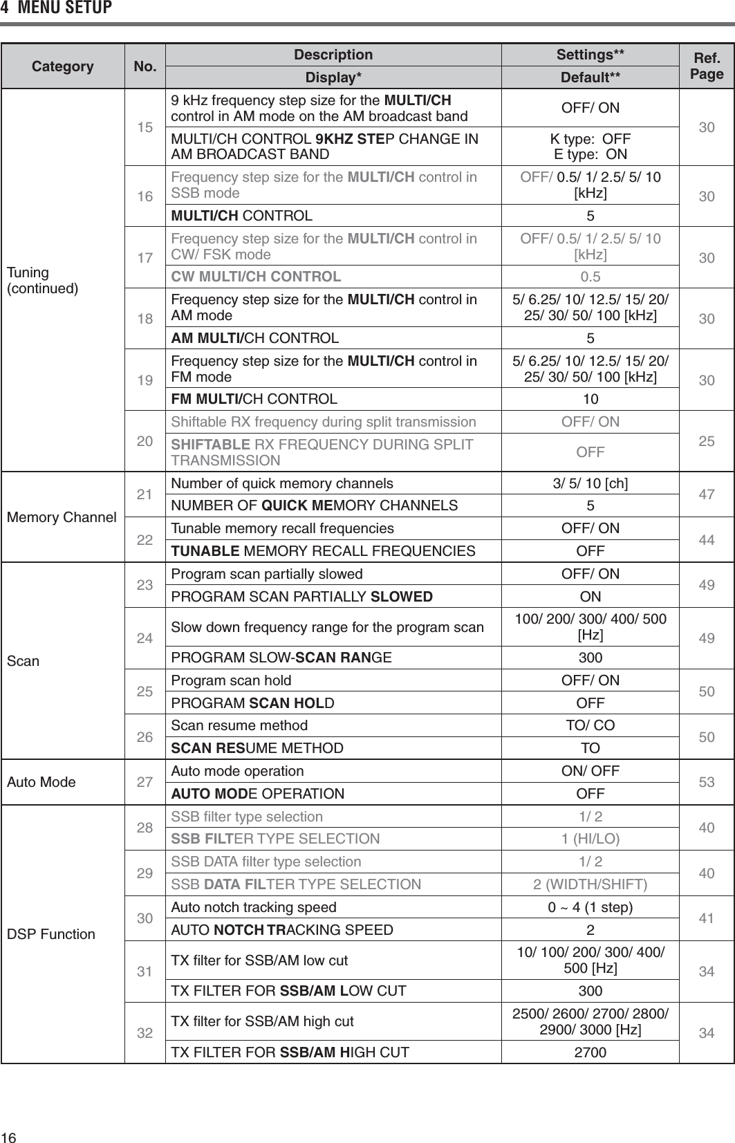
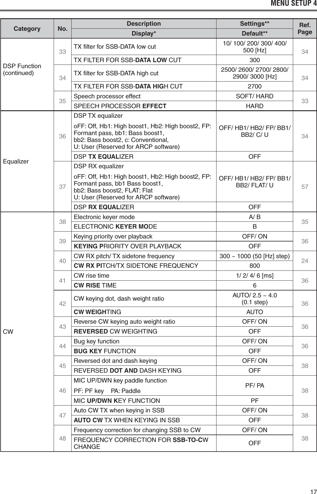
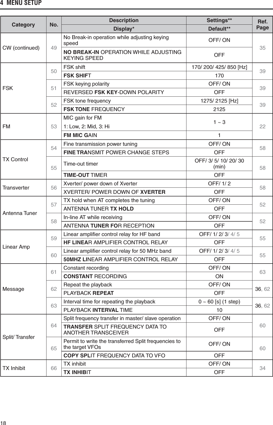
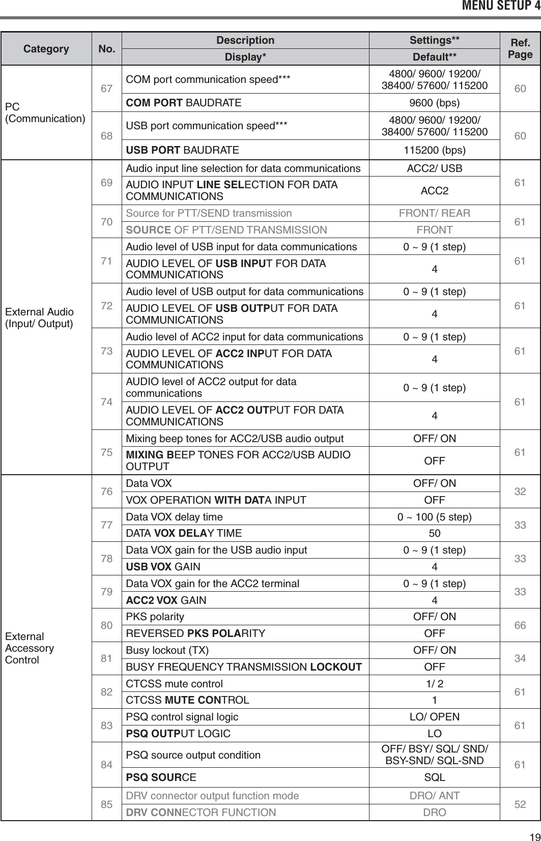
![144 MENU SETUPWHAT IS A MENU?Many functions on this transceiver are selected or configured via a software-controlled Menu, rather than through the physical controls of the transceiver. Once familiar with the Menu system, you will appreciate the versatility it offers. You can customize the various timings, settings, and programming functions on this transceiver to meet your needs without using many controls and switches.MENU A/ MENU BThis transceiver has 2 menus: Menu A and Menu B. These menus contain identical functions and can be configured independently. The transceiver, therefore, allows you to switch between 2 different environments quickly and easily. For example, you can configure Menu A for DXing and contesting while Menu B is for relaxed local ragchewing. By switching from Menu A to Menu B, you can instantly change the Menu configuration and key assignment to suit your current operating style. Or, 2 operators may share a single transceiver by dedicating one Menu to each operator. Both operators can always enjoy their own configuration.MENU ACCESS1 Press [MENU].s 4HE-ENU.OANDSETTINGAPPEARONTHEdisplay, and the explanation of the menu appears on the sub-display.2 Press [A/B (A=B)] to select Menu A or B.s h vORh ” appears, indicating which Menu is selected.3 Press [Q-M.IN]/ [Q-MR] or turn the MULTI/CH CONTROLTOSELECTTHEDESIRED-ENU.Os %ACHTIMEYOUCHANGETHE-ENU.O a different scrolling message appears on the SUBDISPLAYDESCRIBINGTHE-ENU.O4 Press [M.IN]/ [SCAN (SG.SEL)], or Mic [UP]/ [DWN] to select a parameter.5 Press [MENU] to exit Menu mode.QUICK MENUBecause the number of functions this transceiver provides is extraordinary, there are numerous items in each Menu. If you find accessing desired Menu .OSTOBETOOTIMECONSUMINGUSETHE1UICK-ENUTOcreate your own customized, abbreviated Menu. You CANTHENADDTHOSE-ENU.OSWHICHYOUFREQUENTLYUSETOTHE1UICK-ENU#OPYING-ENU.OSTOTHE1UICK-ENUHASNOEFFECTONTHE-ENUPROGRAMMING THE QUICK MENU1 Press [MENU].2 Press [Q-M.IN]/ [Q-MR] or turn the MULTI/CH CONTROLTOSELECTTHEDESIRED-ENU.O3 Press [FINE (F.LOCK)].s h ” appears, indicating that the Menu item has BEENADDEDTOTHE1UICK-ENUs 4OREMOVETHEITEMFROMTHE1UICK-ENUPRESS[FINE (F.LOCK)] AGAINh ” disappears.4 Press [MENU] to exit Menu mode.USING THE QUICK MENU1 Press [MENU].2 Press [MHz].s h ” appears.3 Press [Q-M.IN]/ [Q-MR] or turn the MULTI/CH CONTROLTOSELECTTHEDESIRED1UICK-ENU.O4 Press [M.IN]/ [SCAN (SG.SEL)], or Mic [UP]/ [DWN] to change the current setting for the SELECTED-ENU.Os 7HENTHE-ENUISREGISTEREDTOTHE1UICK-ENULISTh ” appears.5 Press [MENU] TOEXIT1UICK-ENUMODENote: )FTHE1UICK-ENUHASNOTBEENPROGRAMMED0RESS[Q-M.IN]/[Q-MR] or turning the MULTI/CH control in step 2 CAUSESh#(%#+vTOBEOUTPUTIN-ORSECODE](https://usermanual.wiki/JVC-KENWOOD/407110/User-Guide-2411097-Page-22.png)
![21MENU SETUP 4CHARACTER ENTRY7HENCHARACTERENTRYISREQUIREDACURSORWILLAPPEARon the display.1 Move the cursor to the left or right by pressing [Q-M.IN] or [Q-MR].2 Turn the MULTI/CH control or press [M.IN]/ [SCAN (SG.SEL)] to select your desired character.s 9OUCANDELETETHESELECTEDCHARACTERBYpressing [CL].3 2EPEATSTEPSANDTOENTERTHEREMAININGcharacters.4 Press [MENU] to set the entry and to exit character entry mode.s 0RESS[CLR] at any time to cancel character entry mode and return to the Menu selection.Available alphanumeric characters:!"#$%&'()*+,-./01Q2345678Y Z (space) + – / 0 1 2 3 4 5 6 7 8 9Note: 2EFERTOPAGETOCHANGETHE0OWER/NMESSAGEANDPAGETOREGISTERA-EMORY#HANNELNAME](https://usermanual.wiki/JVC-KENWOOD/407110/User-Guide-2411097-Page-29.png)
![225 BASIC COMMUNICATIONSSSB TRANSMISSIONSSB is the most commonly-used mode on the HF Amateur radio bands. Compared with other voice modes, SSB requires only a narrow bandwidth for communications. SSB also allows long distance communications with minimum transmission power.If necessary, refer to “OPERATING BASICS”, beginning on page 10, for details on how to receive.1 Select an operating frequency.2 Press [LSB/USB] until “USB” or “LSB” appears on the operating mode display.s )FTHEDESIREDSIDEBANDh53"vORh,3"vDOESnot appear, select the other sideband first. Then, press [LSB/USB]. The mode indicator changes to your desired sideband.s h53"vREPRESENTSTHEUPPERSIDEBANDAND“LSB” represents the lower sideband. Normally, USB is used for the communications for 10 MHz and above while LSB is used for the frequencies below 10 MHz.3 Press [MIC (CAR)] to adjust the Microphone gain.s 4HECURRENTGAINLEVELAPPEARSONTHESUBdisplay.4 Press and hold Mic [PTT].s 4HE4828,%$LIGHTSREDs 2EFERTOh6/8v[PAGE32} for information on AUTOMATIC4828SWITCHING5 Speak into the microphone and turn the MULTI/CH control so that the ALC meter reflects your voice level but does not exceed the ALC limit.s 3PEAKINYOURNORMALTONEANDLEVELOFVOICESpeaking too close to the microphone or too loudly may increase distortion and reduce intelligibility at the receiving end.s 9OUMAYWANTTOUSETHE3PEECH0ROCESSOR2EFERTOh30%%#(02/#%33/2v[PAGE33} for details.6 Release Mic [PTT] to return to Reception mode.s 4HE4828,%$LIGHTSGREENORTURNSOFFdepending on the SQL control position.7 Press [MIC (CAR)] or [CLR] to exit the Microphone gain adjustment.2EFERTOh#/--5.)#!4).'!)$3vBEGINNINGONpage 30, for information on additional useful operation functions.FM TRANSMISSION&-ISACOMMONMODEFORCOMMUNICATINGON6(&ORUHF frequencies. As for HF and the 6 m band, 29 MHz and 51-54 MHz bands are commonly used FOR&-OPERATION9OUCANALSOUTILIZEMMBANDrepeaters to reach your friends when they are outside or skipped over from your coverage. Although FM requires a wider bandwidth when compared to SSB or AM mode, it has the finest audio quality among these modes. When combined with the full-quieting aspect of FM signals, which suppresses background noise on the frequency, FM can be the best method for maintaining casual communications with your local friends.If necessary, refer to “OPERATING BASICS”, beginning on page 10, for details on how to receive.1 Select an operating frequency.2 Press [FM/AM (FM-N)] until “FM” appears.s )Fh&-vDOESNOTAPPEARSELECTh!-vTHENPRESS[FM/AM (FM-N)]. The mode indicator changes to “FM”.3 Press and hold Mic [PTT].s 4HE4828,%$LIGHTSREDs 2EFERTOh6/8v[PAGE32} for information on AUTOMATIC4828SWITCHING4 Speak into the microphone in your normal voice.s 3PEAKINGTOOCLOSETOTHEMICROPHONEORTOOloudly may increase distortion and reduce intelligibility at the receiving end.s 9OUCANSWITCHTHE-ICROPHONEGAINFOR&-BETWEEN.ORMAL-EDIUMAND(IGHby using Menu No. 53.ORMALISUSUALLYAPPROPRIATEHOWEVERSELECT(IGHIFOTHERstations report that your modulation is weak. 5 Release Mic [PTT] to return to Reception mode.s 4HE4828,%$LIGHTSGREENORTURNSOFFdepending on the SQL control position.2EFERTOh#/--5.)#!4).'!)$3vBEGINNINGONpage 30, for additional information on useful operation functions.Note: Microphone gain adjustment for SSB or AM has no EFFECTIN&-MODE)N&-MODEYOUMUSTSELECT.ORMAL-EDIUMOR(IGHIN-ENU.O53.](https://usermanual.wiki/JVC-KENWOOD/407110/User-Guide-2411097-Page-30.png)
![23BASIC COMMUNICATIONS 5 AM TRANSMISSIONEach mode used on the HF Amateur bands has its OWNADVANTAGES!LTHOUGHLONGDISTANCE$8CONTACTSmay be less common while using AM, the superior audio quality characteristic of AM operation is one reason why some hams prefer this mode.If necessary, refer to “OPERATING BASICS”, beginning on page 10, for details on how to receive.1 Select an operating frequency.2 Press [FM/AM (FM-N)] until “AM” appears.s )Fh!-vDOESNOTAPPEARSELECTh&-vlRSTTHENpress [FM/AM (FM-N)]. The mode indicator changes to “AM”.3 Press [MIC (CAR)] to enter the Microphone gain adjustment mode.s 4HECURRENTGAINLEVELAPPEARSONTHESUBdisplay.4 Press and hold Mic [PTT].s 4HE4828,%$LIGHTSREDs 2EFERTOh6/8v[PAGE]FORINFORMATIONONAUTOMATIC4828SWITCHING5 Speak into the microphone and adjust the MULTI/CH control so that the power meter slightly reflects your voice level.s 3PEAKINYOURNORMALTONEANDLEVELOFVOICESpeaking too close to the microphone or too loudly may increase distortion and reduce intelligibility at the receiving end.s 9OUMAYWANTTOUSETHE3PEECH0ROCESSOR2EFERTOh30%%#(02/#%33/2v[PAGE33} for details.6 Release Mic [PTT] to return to Reception mode.s 4HE4828,%$LIGHTSGREENORTURNSOFFdepending on the SQL control position.7 Press [MIC (CAR)] or [CLR] to exit the Microphone gain adjustment mode.2EFERTOh#/--5.)#!4).'!)$3vBEGINNINGONpage 30, for information on additional useful operation functions.Note: 7HENTHE48POWERMETERREADINGEXCEEDSTHEVALUETHATYOUSPECIlEDINTHE480OWERSETTING[PAGE]DECREASETHEmicrophone gain or adjust your tone and level of voice.NARROW BANDWIDTH FOR FM3ELECTWIDEBANDORNARROWBAND48DEVIATIONdepending on whether the other station is using wide band or narrow band filter for FM mode. While “NAR” appears, the TS-590S transceiver transmits signals in narrow band FM but the reception IF filter bandwidth REMAINSUNCHANGED7IDE4HEDEVIATIONSELECTIONis crucial to avoid audio distortion or insufficient intelligibility that the other station will encounter.1 Press [FM/AM (FM-N)] until “FM” appears.sIf “FM” does not appear, select “AM” first, then press [FM/AM (FM-N)]. The mode indicator changes to “FM”.2 Press and hold [FM/AM (FM-N)] to toggle the SELECTIONBETWEENWIDEANDNARROW48DEVIATIONs h vAPPEARSWHENNARROW48DEVIATIONISselected.CW TRANSMISSIONCW operators know that this mode is very reliable when communicating under worst conditions. It may be true that newer digital modes rival CW as being equally as useful in poor conditions. These modes, however, do not have the long history of service nor the simplicity that CW provides.This transceiver has a built-in electronic keyer that supports a variety of functions. For details on using THESEFUNCTIONSREFERTOh%,%#42/.)#+%9%2v[PAGE35}.If necessary, refer to “OPERATING BASICS”, beginning on page 10, for details on how to receive.1 Select the operating frequency.2 Press [CW/FSK (REV)] until “CW” appears.s )Fh#7vDOESNOTAPPEARSELECTh&3+vlRSTTHENpress [CW/FSK (REV)]. The mode indicator changes to “CW”.s 4OPRECISELYTUNEINANOTHERSTATIONUSE!UTOZero-beat. Refer to “AUTO ZERO-BEAT” [PAGE24}.3 Press [SEND].s 4HE4828,%$LIGHTSRED4 Operate the Keys or Paddle.s !SYOUTRANSMITYOUSHOULDHEARASIDETONEthat lets you monitor your own transmission.5 Press [SEND] to return to Reception mode.s 4HE4828,%$LIGHTSGREENORTURNSOFFdepending on the SQL control setting.](https://usermanual.wiki/JVC-KENWOOD/407110/User-Guide-2411097-Page-31.png)
![245 BASIC COMMUNICATIONSAUTO ZERO-BEATUse Auto Zero-beat before transmitting to tune in a CW station. Auto Zero-beat automatically and exactly matches your transmit frequency with the station you are receiving. Neglecting to do this will reduce your chances of being heard by the other station.1 Tune to the CW signal using the Tuning control.2 Press [CW T. (AGC OFF)] to start Auto Zero-beat while CW is selected for the operating mode.s h#745.%vAPPEARSs 9OURRECEPTIONFREQUENCYAUTOMATICALLYCHANGESSOTHATTHEPITCHTONEOFTHERECEIVEDSIGNALEXACTLYMATCHESTHE48SIDETONE28PITCHFREQUENCYTHATYOUHAVESELECTED2EFERTOh483)$%4/.%280)4#(&2%15%.#9v[BELOW]s 7HENMATCHINGISCOMPLETEDh#745.%vdisappears.s )FMATCHINGISUNSUCCESSFULTHEPREVIOUSfrequency is restored.3 To quit Auto Zero-beat, press [CW T. (AGC OFF)] or [CLR].Note:◆ When using Auto Zero-beat, the matching error is normally within ±5 Hz.◆ Auto Zero-beat may fail if the keying speed of the target station is too slow or if some interference is present.◆ When the RIT function is ON, only RIT frequencies change to make the Auto Zero-beat adjustment.TX SIDETONE/ RX PITCH FREQUENCYAs you send CW, you will hear tones from THETRANSCEIVERSPEAKER4HESEARECALLED48TRANSMISSIONSIDETONES,ISTENINGTOTHESETONESYOUCANMONITORWHATYOUARETRANSMITTING9OUMAYalso use the tones to ensure that your key contacts are closing, the keyer is functioning, or to practice sending without actually putting a signal on the air.28RECEPTIONPITCHREFERSTOTHEFREQUENCYOF#7THATyou hear after tuning in a CW station.On this transceiver, the frequency of the sidetone and 28PITCHAREEQUALANDSELECTABLE!CCESS-ENU.O40 to select the frequency that is most comfortable for you. The selectable range is from 300 Hz to 1000 Hz INSTEPSOF(ZDEFAULTIS(Z4OCHANGETHEVOLUMEOFTHE48SIDETONEACCESSMenu No. 06. The selections range from 1 to 20 and /&&DEFAULTIS10Note:◆ The position of the AF control does not affect the volume of THE48SIDETONE◆ 7HENCHANGINGTHE#7PITCHSIDETONETHESHIFTAMOUNTOFTHERECEIVElLTERISAUTOMATICALLYAPPLIEDTOTHE#7PITCHSIDETONE)N1UICK-EMORYMODETHE#7PITCHSIDETONEis not revised since the receive filter information stored in the 1UICK-EMORYHASPRIORITYCARRIER LEVELWhen using AM, CW, or FSK mode, you can adjust the carrier level.1 Press and hold [MIC (CAR].s 4HECURRENTGAINLEVELAPPEARSONTHESUBdisplay.2 Turn the MULTI/CH control so that the ALC meter reads within the limits of the ALC zone.s &OR!-MODEADJUSTTHEMULTI/CH control so that the ALC meter just begins to indicate.3 Press and hold [MIC (CAR] again or press [CLR] to complete the setting.POWER ON MESSAGEEach time you switch the transceiver ON, h+%.7//$vDEFAULTAPPEARSONTHESUBDISPLAYFORAPPROXIMATELYSECONDS9OUCANPROGRAMYOURFAVORITEMESSAGEINPLACEOFTHEDEFAULTMESSAGE9OUCANENTERAMESSAGEUSINGUPTOCHARACTERS1 Press [MENU], then press [Q-M.IN][Q-MR] or turn the MULTI/CH control to access Menu No 01.2 Press [M.IN][SCAN (SG.SEL)] to begin editing the message.3 Move the cursor to the left or right by pressing [Q-M.IN] or [Q-MR].4 Press [M.IN][SCAN (SG.SEL)] or turn the MULTI/CH control to select your desired character.s 9OUCANDELETETHESELECTEDCHARACTERBYpressing [CL].5 Repeat steps 3 and 4 to enter the remaining characters.6 Press [MENU] to set the entry and exit character entry mode.s 0RESS[CLR] at any time to cancel character entry mode and exit the Menu mode.](https://usermanual.wiki/JVC-KENWOOD/407110/User-Guide-2411097-Page-32.png)
![256 ENHANCED COMMUNICATIONSSPLIT-FREQUENCY OPERATIONUsually you can communicate with other stations using a single frequency for receiving and transmitting. In this case, you select only one frequency on either VFO A or VFO B. However, there are cases where you must select one frequency for receiving and a different frequency for transmitting. This requires the use of 2 VFOs. This is referred to as “split-frequency operation”. One typical case which requires this type of operation is when you use an FM repeater {page 26}. Another typical case is when you call a rare DX station.When a rare or desirable DX station is heard, that operator may immediately get many simultaneous responses. Often, such a station is lost under the noise and confusion of many calling stations. If you find that you are suddenly being called by many operators, it is your responsibility to control the situation. You may announce that you will be “listening up 5 (kHz, from your present transmission frequency)”, or “listening down between 5 and 10 (kHz)”.1 Press [A/B (A=B)] to select VFO A or VFO B.s h ” or “ ” appears to show which VFO is selected.2 Select an operating frequency.s 4HISFREQUENCYWILLBEUSEDFORTRANSMISSIONs 4OCOPYTHESELECTED6&/FREQUENCYTOTHEother VFO, press and hold [A/B (A=B)].3 Press [A/B (A=B)] to select the other VFO.4 Select an operating frequency.s 4HISFREQUENCYWILLBEUSEDFORRECEPTION5 Press [SPLIT].s h ” appears.s %ACHTIMEYOUPRESS[A/B (A=B)], the reception and transmission frequencies are swapped.6 To quit split-frequency operation, press [SPLIT] again.s h ” disappears.SHIFTABLE RX FREQUENCY DURING SPLIT TRANSMISSIONWhen the shiftable function of the RX frequency in split transmission is set to ON, it is possible to change the RX frequency by turning the Tuning control during split transmission. (When it is set to OFF, the TX frequency changes by turning the Tuning control during split transmission.)1 Press [MENU], then press [Q-M.IN]/ [Q-MR] or turn the MULTI/CH control to select Menu No. 20.2 Press [M.IN]/ [SCAN (SG.SEL)] to select “on” 3 Press [MENU] to exit Menu mode.s 7HENYOUSWITCHTHETRANSCEIVER/.WHILETHISfunction is set to ON, the decimal point at the right end digit of the main display flashes for approximately 2 seconds after the Power On message is displayed.DIRECTLY ENTERING THE FREQUENCY SPLIT SPECIFIED BY A DXerTo directly enter the difference between the TX and RX frequencies specified by a DXer, follow the instruction below while receiving on the main band of a signal from the DXer.1 Press and hold [SPLIT].s h ” blinks.2 %NTERTHEFREQUENCYDIFFERENCETHEhSPLITvINTHEorder of kHz as specified by the DX station.If the frequency specified by the DXer is higher than your current frequency, enter the specified frequency in the order of kHz using the numeric and band-select keypad. Conversely, if the specified frequency is lower, prefix a value of "0" to the frequency.s &OREXAMPLEENTERAVALUEOFTOINCREMENTthe frequency by 5 kHz, and enter a value of "05" to decrement the frequency by 5 kHz.s h ” switches from split operation to simplex operation.Note:◆ Pressing [SPLIT] switches from split operation to simplex operation.◆ To temporarily receive using the transmit frequency, use the 4&3%4FUNCTIONTURN THE TUNING CONTROL TO SEARCH FOR THE TRANSMIT FREQUENCYTo directly search for the transmit frequency by rotating the Tuning control, follow the instruction below while receiving on the main band of a signal from the DX station.1 Press and hold [SPLIT].s h ” blinks.2 Turn the Tuning control to search for the frequency.s 4HEFREQUENCYCANBECHANGEDEVENIFTHEfrequency has been locked.s 0RESS[CLR] to stop searching.3 Press [SPLIT] to end.s 4HEFREQUENCYISCONlGUREDASTHETRANSMITfrequency and split operation begins.s h ” lights.](https://usermanual.wiki/JVC-KENWOOD/407110/User-Guide-2411097-Page-33.png)
![266 ENHANCED COMMUNICATIONSTF-SET (TRANSMISSION FREQUENCY SET)4&3%4ALLOWSYOUTOTEMPORARILYSWITCHYOURtransmission frequency and reception frequency. Canceling this function immediately restores the original transmission and reception frequencies. "YACTIVATING4&3%4YOUCANLISTENONYOURTRANSMITfrequency, and change it while listening. This allows you to check whether or not the newly selected transmission frequency is free of interference.1 Configure split-frequency operation as explained in the previous section.2 Press and hold [TF-SET], then turn the Tuning control or press Mic [UP]/ [DWN] to change the transmission frequency.s 4HETRANSCEIVERRECEIVESONTHEFREQUENCYASyou change, but the frequency shown on the sub-display (the original reception frequency) stays unchanged.3 Release [TF-SET].s 9OUARENOWRECEIVINGAGAINONYOURORIGINALreception frequency.Successfully contacting a DX station in a pileup often depends on making a well-timed call on a clear frequency. That is, it is important to select a relatively clear transmission frequency and to transmit at the exact instant when the DX station is listening but the majority of the groups aren’t transmitting. Switch your reception and transmission frequencies by using THE4&3%4FUNCTIONANDLISTENTOYOURTRANSMISSIONfrequency. You will soon learn the rhythm of the DX station and the pileup. The more proficient you become at using this function, the more DX stations you will contact.Note:◆ 4&3%4ISDISABLEDWHILETRANSMITTING◆ You can change the transmission frequency even when the Frequency lock function is ON.◆ An RIT offset frequency is not added; however, an XIT offset FREQUENCYISADDEDTOTHETRANSMITFREQUENCYDURING4&3%4FM REPEATER OPERATIONMost Amateur radio voice repeaters use a separate reception and transmission frequency. The transmission frequency may be higher or lower than the reception frequency. In addition, some repeaters may require the transceiver to transmit a subtone before the repeater can be used.Compared to simplex communication, you can usually transmit over much greater distances by using a repeater. Repeaters are typically located on a mountain top or other elevated location. Often THEYOPERATEATHIGHER%20%FFECTIVE2ADIATEDPower) than a typical station. This combination of ELEVATIONANDHIGH%20ALLOWSCOMMUNICATIONSOVERconsiderable distances.HF/ 6 m band repeaters usually operate in the 29 MHz FM sub-band and 51-54 MHz band. This special service combines the advantages of FM operation, good fidelity with noise and interference immunity, with the excitement of HF DX (long DISTANCECOMMUNICATIONS%VENONAQUIETDAY 10 m FM provides reliable around-town communications with the potential for sudden DX from across the country or around the world.Note:◆ When programming 2 separate frequencies using 2 VFOs, be sure to select FM mode on both VFOs.◆ When operating through a repeater, over deviation caused by speaking too loudly into the microphone can cause your signal to “talk-off” (break up) through the repeater.29.520 MHz88.5 Hz29.520 MHz88.5 Hz29.620 MHz29.620 MHz1 Press [A/B (A=B)] to select VFO A or VFO B.s h ” or “ ” appears to show which VFO is selected.2 Turn the Tuning control or the MULTI/CH control to select the reception frequency.3 Press [FM/AM (FM-N)] to select FM mode.4 Press and hold [A/B (A=B)] to duplicate the frequencies and other data to the other VFO.5 Turn the Tuning control or the MULTI/CH control to select the transmission frequency.6 Press [AGC/T (SEL] to turn the Tone function ON if the repeater requires a subtone.s h ” appears.s 2EFERTOh3ELECTINGA4ONE&REQUENCYvFORMOREdetails on the subtone {page 27}.](https://usermanual.wiki/JVC-KENWOOD/407110/User-Guide-2411097-Page-34.png)
![27ENHANCED COMMUNICATIONS 6 ■ Activating the Tone Function1 Confirm that FM mode has been selected on the VFO(s) {page 10}.s 7HENUSING6&/SYOUMUSTSELECT&-mode on both VFOs.2 Press [AGC/T (SEL)].s h ” appears.Note: You cannot use the Tone function with the CTCSS function.■ Selecting a Tone Frequency1 While “ ” appears (Tone function is ON), press and hold [AGC/T (SEL)].s 4HECURRENTTONEFREQUENCYAPPEARS The default is 88.5 Hz.2 Turn the MULTI/CH control to select the desired tone frequency.s 4HEAVAILABLETONEFREQUENCIESARELISTEDINthe table below.3 Press and hold [AGC/T (SEL)] or press [CLR] to complete the setting.No. Freq. (Hz) No. Freq. (Hz) No. Freq. (Hz) No. Freq. (Hz)00 67.0 11 97.4 22 141.3 33 206.501 69.3 12 100.0 23 146.2 34 210.702 71.9 13 103.5 24 151.4 35 218.103 74.4 14 107.2 25 156.7 36 225.704 77.0 15 110.9 26 162.2 37 229.105 79.7 16 114.8 27 167.9 38 233.606 82.5 17 118.8 28 173.8 39 241.807 85.4 18 123.0 29 179.9 40 250.308 88.5 19 127.3 30 186.2 41 254.109 91.5 20 131.8 31 192.8 42 175010 94.8 21 136.5 32 203.5 -- --Note:◆ You can select a tone frequency independent of a CTCSS frequency.◆ When 1750 Hz is selected, the transceiver sends a 500 ms tone burst each time transmission starts. You cannot transmit 1750 Hz tone manually. s 4OQUITTHE3UBTONEFUNCTIONPRESS[AGC/T (SEL)] twice.7 Press [SPLIT].s h ” appears.8 Press [A/B (A=B)] to return to the original reception frequency.9 Press Mic [PTT] to transmit.s 4HE6&/CHANGESTOTHEOTHER6&/TOTRANSMITs %ACHTIMEYOUPRESS[A/B (A=B)], the reception and transmission frequencies are swapped.10 Press [SPLIT] to quit split-frequency operation.s h ” disappears.The data that you select in steps 1 to 8 can be stored in memory. Refer to “Split-Frequency Channels” {page 43}.Note:◆ When operating through a repeater, over deviation caused by speaking too loudly into the microphone can cause your signal to “talk-off” (break up) through the repeater.◆ To check the tone frequency stored in a memory channel, recall the desired memory channel and press [AGC/T (SEL)].TRANSMITTING A TONEIn general, FM repeaters require the transceiver to transmit a sub-audible tone to prevent other repeaters on the same frequency from locking each other up. The required tone frequency differs among repeaters. Repeaters also differ in their requirements for either continuous or burst tones. For the appropriate selections for your accessible repeaters, consult your local repeater reference.After completing the tone settings, pressing and holding Mic [PTT] causes the transceiver to transmit the selected tone. If you have selected a 1750 Hz tone, the transceiver sends a 500 ms tone burst each time transmission starts.Note: If you store tone settings in a memory channel, you need NOTREPROGRAMEACHTIME2EFERTOh-%-/29&%!452%3v{page 43}.](https://usermanual.wiki/JVC-KENWOOD/407110/User-Guide-2411097-Page-35.png)
![286 ENHANCED COMMUNICATIONS8 Turn the MULTI/CH control to select the appropriate CTCSS frequency.s 4HESELECTABLE#4#33FREQUENCIESARELISTEDINthe table below.9 Press and hold [AGC/T (SEL)] or press [CLR] to complete the setting.No. Freq. (Hz) No. Freq. (Hz) No. Freq. (Hz) No. Freq. (Hz)00 67.0 11 97.4 22 141.3 33 206.501 69.3 12 100.0 23 146.2 34 210.702 71.9 13 103.5 24 151.4 35 218.103 74.4 14 107.2 25 156.7 36 225.704 77.0 15 110.9 26 162.2 37 229.105 79.7 16 114.8 27 167.9 38 233.606 82.5 17 118.8 28 173.8 39 241.807 85.4 18 123.0 29 179.9 40 250.308 88.5 19 127.3 30 186.2 41 254.109 91.5 20 131.8 31 192.8 -- --10 94.8 21 136.5 32 203.5 -- --You will hear calls only when the selected tone is received. To answer the call, press and hold Mic [PTT], then speak into the microphone.Skip steps 7 and 8 if you have already programmed the appropriate CTCSS frequency.Note: ◆ When using split-frequency operation, select FM mode on both VFOs to use CTCSS.◆ You can select a CTCSS frequency independent of a tone frequency.◆ You cannot use the CTCSS function with the Tone function.CTCSS FREQUENCY ID SCANThis function scans through all CTCSS frequencies to identify the incoming CTCSS frequency on a received signal. You may find this useful when you cannot recall the CTCSS frequency that the other persons in your group are using.1 While the CTCSS function is ON, press and hold [AGC/T (SEL)].s 4HECURRENT#4#33FREQUENCYAPPEARS2 Press [SCAN (SG.SEL)] to activate the CTCSS frequency ID scan.s 7HILETHETRANSCEIVERISRECEIVINGASIGNALh ” blinks and every CTCSS frequency is scanned. When the CTCSS frequency is identified, the transceiver stops scanning and the identified frequency is displayed.TONE FREQUENCY ID SCANThis function scans through all tone frequencies to identify the incoming tone frequency on a received signal. You may find this useful when you do not know the tone frequency that the repeater uses.1 While the Tone function is ON (“ ” is visible), press and hold [AGC/T (SEL)].s 4HECURRENTTONEFREQUENCYAPPEARS2 Press [SCAN (SG.SEL)] to activate the Tone frequency ID scan.s 7HILETHETRANSCEIVERISRECEIVINGASIGNALh ” blinks and every tone frequency is scanned. When the tone frequency is identified, the transceiver stops scanning and the identified frequency is displayed.s 0RESS[SCAN (SG.SEL)] or [CLR] to stop scanning while the tone frequency ID scan is active.s 0RESS[SCAN (SG.SEL)] again to resume scanning.Note: Received signals are audible while scanning is in progress.FM CTCSS OPERATIONYou may sometimes want to hear calls only from specific persons. When using FM mode, the Continuous Tone Coded Squelch System (CTCSS) allows you to ignore (not hear) unwanted calls from other persons who are using the same frequency. A CTCSS tone is sub-audible and is selectable from among the 42 tone frequencies. Select the same CTCSS tone as the other stations in your group. You will not hear calls from stations other than those using the same CTCSS tone.Note: CTCSS does not cause your conversation to be private. It only relieves you from listening to unwanted conversations.1 Press [A/B (A=B)] to select VFO A or VFO B.s h ” or “ ” appears to show which VFO is selected.2 Select the 29 MHz band or the 51-54 MHz band using [28 (9)] or [50 (0)].3 Select the desired frequency with the Tuning control or MULTI/CH control.4 Press [FM/AM (FM-N)] to select FM mode.5 Turn the SQL control to adjust the squelch.6 Press [AGC/T (SEL)] until “ ” appears.7 While “ ” is visible, press and hold [AGC/T (SEL)].s 4HECURRENT#4#33FREQUENCYAPPEARSDEFAULTis 88.5 Hz).](https://usermanual.wiki/JVC-KENWOOD/407110/User-Guide-2411097-Page-36.png)
![29ENHANCED COMMUNICATIONS 6 s 0RESS[SCAN (SG.SEL)] or [CLR] to stop scanning while the CTCSS frequency ID scan is active.s 0RESS[SCAN (SG.SEL)] again to resume scanning.Note: Received signals are audible while scanning is in progress.CROSS TONEUse this feature when using different uplink and downlink tones to access a repeater. You can set a transmission Tone frequency and reception CTCSS frequency to different frequencies.To set the transmission tone:1 Press [A/B (A=B)] to select VFO A or VFO B.2 Select your desired transmission frequency.3 Press [FM/AM (FM-N)] to select FM.4 Press [AGC/T (SEL)] until “ ” appears.5 Press and hold [AGC/T (SEL)], then turn the MULTI/CH control to select your desired Tone frequency.6 Press and hold [AGC/T (SEL)] or press [CLR] to complete the setting.To set the reception tone:1 Press [A/B (A=B)] to select the other VFO.2 Select your desired reception frequency.3 Press [FM/AM (FM-N)] to select FM.4 Press [AGC/T (SEL)] until “ ” appears.5 Press and hold [AGC/T (SEL)], then turn the MULTI/CH control to select your desired CTCSS frequency.6 Press and hold [AGC/T (SEL)] or press [CLR] to complete the setting.To set the Cross tone:1 Press [SPLIT].s h30,)4vAPPEARSONTHEDISPLAY2 Press [AGC/T (SEL)] until “ ” appears.Note: hen the cross tone function is ON, the Tone and CTCSS frequency cannot be changed. To change the Tone or CTCSS frequency, press [AGC/T (SEL)] to turn Tone or CTCSS ON, then change the setting.](https://usermanual.wiki/JVC-KENWOOD/407110/User-Guide-2411097-Page-37.png)