JVC KENWOOD 407110 Scanning Receiver User Manual
JVC KENWOOD Corporation Scanning Receiver
Users Manual

© B5A-0180-00 (K, E)
INSTRUCTION MANUAL
HF/50MHz TRANSCEIVER
TS-590SG
COPYRIGHTS FOR THIS MANUAL
JVC KENWOOD Corporation shall own all copyrights
and other intellectual properties for the product and
the software and for all manuals and documents
attached to the product and the software.
A user is required to obtain approval from
JVC KENWOOD corporation, in writing, prior to
redistributing this document on a personal web page
or via packet communication.
A user is prohibited from assigning, renting, leasing or
reselling the document.
JVC KENWOOD Corporation does not warrant
that quality and functions described in this manual
comply with each user's purpose of use and, unless
specifically described in this manual, JVC KENWOOD
Corporation shall be free from any responsibility for
any defects and indemnities for any damages or
losses.
INDEMNITY
s JVC KENWOOD Corporation takes all appropriate
measures to ensure all descriptions in this manual
are accurate; however, this manual may still contain
typographical errors (“typos”) and expressions that
are misleading. JVC KENWOOD Corporation is
entirely free from any responsibilities arising from
any losses or damages caused by such typos or
expressions.
s JVC KENWOOD Corporation has the right to
change or improve the product specifications, etc.,
described in this manual without prior notice. JVC
KENWOOD Corporation is entirely free from any
responsibilities for any losses or damages caused
by such changes and improvements.
s JVC KENWOOD Corporation is entirely free from
any responsibilities for any failures, damages or
losses arising from, or in connection with, use of
the transceiver with or connected to any external
equipment. Failures, damages or losses shall
include the failures, damages or losses that may
occur at the PC connected to the transceiver or in
storage devices having memory area such as a USB
flash drive. JVC KENWOOD Corporation is entirely
free from any responsibilities for any secondary
failures, damages or losses, including but not limited
to the loss or damage of data or data files stored in
these memories.
s JVC KENWOOD Corporation does not warrant
that the quality and functions described in this
manual comply with your purpose of use and,
unless specifically described in this manual, JVC
KENWOOD Corporation shall be free from any
responsibilities for any defects and indemnities for
any damages or losses. Selection and installation of
any external equipment shall be done at your own
risk. You are fully responsible for the use and effects
of external equipment.
s JVC KENWOOD Corporation shall be free from
any responsibilities for any incidental losses or
damages, such as missing communications or call
opportunities caused by a failure or performance
error of the transceiver.
i
THANK YOU
Thank you for choosing this KENWOOD TS-590S
transceiver. It has been developed by a team of
engineers determined to continue the tradition of
excellence and innovation in KENWOOD transceivers.
This transceiver features a Digital Signal Processing
(DSP) unit to process IF and AF signals. By taking
maximum advantage of DSP technology, the TS-590S
transceiver gives you enhanced interference reduction
capabilities and improves the quality of audio. You will
notice the differences when you fight QRM and QRN.
As you learn how to use this transceiver, you will also
find that KENWOOD is pursuing “user friendliness”.
For example, each time you change the Menu No. in
Menu mode, you will see scrolling messages on the
display, telling you what you are selecting.
Though user friendly, this transceiver is technically
sophisticated and some features may be new to you.
Consider this manual to be a personal tutorial from the
designers. Allow the manual to guide you through the
learning process now, then act as a reference in the
coming years.
FEATURES
s !LLMODEOPERATIONFROM(&TO-(ZAMATEUR
radio band
s (ZK(ZROOlNGlLTER
s 3UPERIOR#.RESPONSEBYTHE$$3LARGELY
decreases the noise of the undesired signal.
s )&$30THROUGHTHEADOPTIONOFBITmOATINGPOINT
DSP
s $IGITAL.OISE"LANKER
s 0#INTERFACEVIAA5NIVERSAL3ERIAL"USPORT
(B-type)
s $RIVEOUTPUTAND28ONLYANTENNACONNECTOR
s $IRECTBANDKEYS
s "UILTIN!NTENNA4UNERFORTHE(&-(ZBAND
s 7OUTPUTPOWERFOR33"#7&3+&-AND
7OUTPUTPOWERFOR!-
NOTICE TO THE USER
One or more of the following statements may be
applicable for this equipment.
FCC WARNING
This equipment generates or uses radio frequency energy.
Changes or modifications to this equipment may cause harmful
interference unless the modifications are expressly approved
in the instruction manual. The user could lose the authority to
OPERATETHISEQUIPMENTIFANUNAUTHORIZEDCHANGEORMODIlCATION
is made.
INFORMATION TO THE DIGITAL DEVICE USER REQUIRED
BY THE FCC
This equipment has been tested and found to comply with the
LIMITSFORA#LASS"DIGITALDEVICEPURSUANTTO0ARTOFTHE
FCC Rules. These limits are designed to provide reasonable
protection against harmful interference in a residential
installation.
This equipment generates, uses and can generate radio
frequency energy and, if not installed and used in accordance
with the instructions, may cause harmful interference to radio
COMMUNICATIONS(OWEVERTHEREISNOGUARANTEETHATTHE
interference will not occur in a particular installation. If this
equipment does cause harmful interference to radio or television
reception, which can be determined by turning the equipment off
and on, the user is encouraged to try to correct the interference
by one or more of the following measures:
s 2EORIENTORRELOCATETHERECEIVINGANTENNA
s )NCREASETHESEPARATIONBETWEENTHEEQUIPMENTAND
receiver.
s #ONNECTTHEEQUIPMENTTOANOUTLETONACIRCUITDIFFERENTFROM
that to which the receiver is connected.
s #ONSULTTHEDEALERFORTECHNICALASSISTANCE
This device complies with Industry Canada
licenseexempt RSS standard(s). Operation is subject
TOTHEFOLLOWINGTWOCONDITIONSTHISDEVICEMAYNOT
CAUSEINTERFERENCEANDTHISDEVICEMUSTACCEPT
any interference, including interference that may
cause undesired operation of the device.
This product is designed for connection to an IT power
distribution system.
Information on Disposal of Old Electrical and Electronic Equipment
and Batteries (applicable for countries that have adopted separate
waste collection systems)
Products and batteries with the symbol (crossed-out
wheeled bin) cannot be disposed as household waste.
Old electrical and electronic equipment and batteries
should be recycled at a facility capable of handling these
items and their waste byproducts.
Contact your local authority for details in locating a recycle
facility nearest to you.
Proper recycling and waste disposal will help conserve
resources whilst preventing detrimental effects on our
health and the environment.
Firmware Copyrights
The title to and ownership of copyrights for firmware embedded in
+%.7//$PRODUCTMEMORIESARERESERVEDFOR*6#+%.7//$
Corporation.
NOTIFICATION
This equipment complies with the essential requirements of
$IRECTIVE%#
The use of the warning symbol means the equipment is
subject to restrictions of use in certain countries.
This equipment requires a licence and is intended for use in
the countries below.
AT"% $+ FI FR $% GRIS )%
IT LI ,5 NL NO PT%3 3% #(
GB CYCZ%% (5 ,6 LT M T PL
3+ SI BG RO (2
)3/
ii
BEFORE STARTING
Amateur radio regulations vary from country to
country. Confirm your local amateur radio regulations
and requirements before operating the transceiver.
$EPENDINGONTHESIZEANDTYPEOFVEHICLETHE
maximum transmission output power for the mobile
operation will vary. The maximum transmission output
power is usually specified by the car manufacturer
to avoid interference with other electric devices used
in the vehicle. Consult your car manufacturer and
amateur radio equipment dealer for the requirements
and installation.
MARKET CODES
K-type: The Americas
E-type: %UROPE
The market code is shown on the carton box.
Refer to the specifications {page } for information on
the available operating frequencies.
WRITING CONVENTIONS FOLLOWED
The writing conventions described below have
been followed to simplify instructions and avoid
unnecessary repetition.
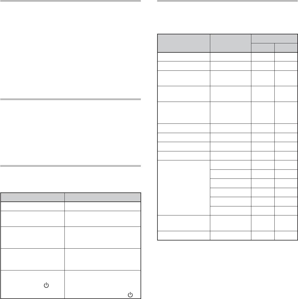
Instruction Action
Press [KEY].0RESSANDRELEASE+%9
Press Mic [KEY].0RESSANDRELEASE+%9ON
the microphone.
Press and hold [KEY].
0RESSANDHOLD+%9DOWN
for a moment, then release
+%9
(OLD[KEY].
0RESSANDHOLD+%9DOWN
until instructed to release
+%9
Press [KEY] + [].
7ITHTHETRANSCEIVERPOWER
/&&PRESSANDHOLD+%9
then switch the transceiver
power ON by pressing [].
SUPPLIED ACCESSORIES
After carefully unpacking the transceiver, identify the
ITEMSLISTEDINTHETABLEBELOW7ERECOMMENDYOU
keep the box and packing materials in case you need
to repack the transceiver in the future.
Accessory Comment Quantity
K-type E-type
Microphone
DC power cable
Line filter (with
retaining band) –
Fuse !FOR$#
power cable
Fuse
!FORAN
external
antenna tuner
DIN plug PIN
DIN plug PIN
Screw set For bracket
Plastic spacer For bracket 4 4
Instruction Manual
%NGLISH
French
Spanish –
Italian –
German –
Dutch –
Schematic
diagram –
7ARRANTY#ARD

iii
PRECAUTIONS
Please observe the following precautions to prevent
fire, personal injury, and transceiver damage:
s #ONNECTTHETRANSCEIVERONLYTOAPOWERSOURCE
as described in this manual or as marked on the
transceiver itself.
s 2OUTEALLPOWERCABLESSAFELY%NSURETHEPOWER
cables can neither be stepped upon nor pinched
by items placed near or against the cables.
0AYPARTICULARATTENTIONTOLOCATIONSNEAR!#
RECEPTACLES!#OUTLETSTRIPSANDPOINTSOFENTRYTO
the transceiver.
s 4AKECARENOTTODROPOBJECTSORSPILLLIQUIDINTOTHE
transceiver through enclosure openings. Metal
objects, such as hairpins or needles, inserted into
the transceiver may contact voltages resulting in
serious electrical shocks. Never permit children to
insert any objects into the transceiver.
s $ONOTATTEMPTTODEFEATMETHODSUSEDFOR
grounding and electrical polarization in the
transceiver, particularly involving the power input
cable.
s !DEQUATELYGROUNDALLOUTDOORANTENNASFORTHIS
transceiver using approved methods. Grounding
helps protect against voltage surges caused by
lightning. It also reduces the chance of a build-up
of static charge.
EXAMPLE OF ANTENNA GROUNDING
ANTENNA
LEAD IN
WIRE
GROUND
CLAMP
ELECTRIC SERVICE
EQUIPMENT
ANTENNA
DISCHARGE UNIT
GROUNDING
CONDUCTORS
GROUND CLAMPS
POWER SERVICE
GROUNDING ELECTRODE
SYSTEM
s -INIMUMRECOMMENDEDDISTANCEFORANOUTDOOR
antenna from power lines is one and one-half
times the vertical height of the associated antenna
SUPPORTSTRUCTURE4HISDISTANCEALLOWSADEQUATE
clearance from the power lines if the support
structure fails for any reason.
s ,OCATETHETRANSCEIVERSOASNOTTOINTERFEREWITHITS
VENTILATION$ONOTPLACEBOOKSOROTHEREQUIPMENT
on the transceiver that may impede the free
movement of air. Allow a minimum of 10 cm
(4 inches) between the rear of the transceiver and
the wall or operating desk shelf.
s $ONOTUSETHETRANSCEIVERNEARWATERORSOURCESOF
moisture. For example, avoid use near a bathtub,
sink, swimming pool, or in a damp basement or
attic.
s 4HEPRESENCEOFANUNUSUALODORORSMOKEIS
often a sign of trouble. Immediately turn the
POWER/&&ANDREMOVETHEPOWERCABLE#ONTACT
a KENWOOD service station or your dealer for
advice.
s ,OCATETHETRANSCEIVERAWAYFROMHEATSOURCES
such as a radiator, stove, amplifier or other devices
that produce substantial amounts of heat.
s $ONOTUSEVOLATILESOLVENTSSUCHASALCOHOLPAINT
thinner, gasoline, or benzene to clean the cabinet
of the transceiver. Use only a clean cloth with
warm water or a mild detergent.
s $ISCONNECTTHEINPUTPOWERCABLEFROMTHEPOWER
source when the transceiver is not used for long
periods of time.
s 2EMOVETHETRANSCEIVERSENCLOSUREONLYTODO
accessory installations described in this manual or
accessory manuals. Follow provided instructions
carefully, to avoid electrical shocks. If unfamiliar
with this type of work, seek assistance from an
experienced individual, or have a professional
technician do the task.
s %NLISTTHESERVICESOFQUALIlEDPERSONNELINTHE
following cases:
A 4HEPOWERSUPPLYORPLUGISDAMAGED
B /BJECTSHAVEFALLENINTOORLIQUIDHASSPILLEDINTO
the transceiver.
C 4HETRANSCEIVERHASBEENEXPOSEDTORAIN
D 4HETRANSCEIVERISOPERATINGABNORMALLYOR
performance has seriously degraded.
E 4HETRANSCEIVERHASBEENDROPPEDORTHE
enclosure damaged.
s $ONOTATTEMPTTOPERFORMANYKINDOFCONlGURATION
or menu setup while driving.
s $ONOTWEARHEADPHONESWHILEDRIVING
s )NSTALLTHETRANSCEIVERINASAFEANDCONVENIENT
position inside your vehicle so as not to subject
YOURSELFTODANGERWHILEDRIVING#ONSULTYOURCAR
dealer for the transceiver installation to ensure
safety.
s (&-(ZMOBILEANTENNASARELARGERAND
HEAVIERTHAN6(&5(&ANTENNAS4HEREFOREUSE
a strong and rigid mount to safely and securely
INSTALLTHE(&-(ZMOBILEANTENNA

iv
CONTENTS
TX SIDETONE/ RX PITCH FREQUENCY .........................24
CARRIER LEVEL ...............................................................24
POWER ON MESSAGE ......................................................24
CHAPTER 6 ENHANCED COMMUNICATIONS
SPLIT-FREQUENCY OPERATION ......................................25
SHIFTABLE RX FREQUENCY DURING SPLIT
TRANSMISSION ............................................................ 25
DIRECTLY ENTERING THE FREQUENCY SPLIT
SPECIFIED BY A DXER ..................................................25
TURN THE TUNING CONTROL TO SEARCH FOR THE
TRANSMIT FREQUENCY ...............................................25
TF-SET (TRANSMISSION FREQUENCY SET) .................26
FM REPEATER OPERATION ..............................................26
TRANSMITTING A TONE ...............................................27
Activating the Tone Function ....................................27
Selecting a Tone Frequency .....................................27
TONE FREQUENCY ID SCAN .............................................28
FM CTCSS OPERATION ....................................................28
CTCSS FREQUENCY ID SCAN .......................................28
CROSS TONE ....................................................................29
CHAPTER 7 COMMUNICATING AIDS
RECEPTION ......................................................................30
SELECTING YOUR FREQUENCY ....................................30
Direct Frequency Entry ............................................30
Frequency Entry History ..........................................30
Using the MHz key ...................................................30
Quick QSY ...............................................................30
Fine Tuning ..............................................................31
Tuning Control Adjustment Rate ..............................31
Equalizing VFO Frequencies (A=B) ...........................31
RIT (RECEIVE INCREMENTAL TUNING) ........................31
AGC (AUTOMATIC GAIN CONTROL)..............................31
AGC Time Constant Adjustment ...............................31
TRANSMISSION ...............................................................32
VOX (VOICE-OPERATED TRANSMISSION) ...................32
Microphone Input Level ...........................................32
Delay Time ...............................................................32
Anti-VOX Adjustment ...............................................32
Data VOX .................................................................32
Data VOX Delay Time ...............................................33
USB/ ACC2 VOX Gain...............................................33
SPEECH PROCESSOR ...................................................33
Speech Processor Effect ..........................................33
XIT (TRANSMIT INCREMENTAL TUNING) .....................33
CUSTOMIZING TRANSMISSION SIGNAL
CHARACTERISTICS .......................................................34
TX Filter Bandwidth (SSB/ AM) ................................34
TX Filter Bandwidth (LSB-DATA/ USB-DATA) ...........34
TX Equalizer (SSB/ SSB-DATA / FM/ FM-DATA/ AM/
AM-DATA) ................................................................34
TRANSMIT INHIBIT .......................................................34
BUSY LOCKOUT ............................................................34
CHANGING FREQUENCY WHILE TRANSMITTING .........34
CW BREAK-IN ...................................................................35
USING SEMI BREAK-IN OR FULL BREAK-IN .................35
ELECTRONIC KEYER ........................................................35
ELECTRONIC KEYER MODE ..........................................35
CHANGING KEYING SPEED ...........................................35
Invalid Break-In Operation .......................................35
RISE TIME OF CW .........................................................36
AUTO WEIGHTING ........................................................36
THANK YOU .........................................................................i
FEATURES ...........................................................................i
NOTICE TO THE USER .........................................................i
BEFORE STARTING ............................................................. ii
MARKET CODES ................................................................. ii
WRITING CONVENTIONS FOLLOWED ................................ ii
SUPPLIED ACCESSORIES .................................................. ii
PRECAUTIONS .................................................................. iii
CONTENTS ........................................................................ iv
CHAPTER 1 INSTALLATION
ANTENNA CONNECTION .....................................................1
GROUND CONNECTION ......................................................1
LIGHTNING PROTECTION ..................................................1
DC POWER SUPPLY CONNECTION ....................................1
UTILIZING THE BAIL ...........................................................2
REPLACING FUSES ...........................................................2
ACCESSORY CONNECTIONS ..............................................2
FRONT PANEL .................................................................2
Headphones (PHONES) .............................................2
Microphone (MIC) .....................................................2
REAR PANEL ...................................................................2
External Speaker (EXT.SP) .........................................2
Keys for CW (PADDLE and KEY) ................................2
CHAPTER 2 GETTING ACQUAINTED
FRONT PANEL ....................................................................4
LCD DISPLAY .....................................................................7
REAR PANEL ......................................................................9
MICROPHONE ....................................................................9
CHAPTER 3 OPERATING BASICS
SWITCHING POWER ON/ OFF ..........................................10
ADJUSTING THE VOLUME ...............................................10
AF (AUDIO FREQUENCY) GAIN .....................................10
RF (RADIO FREQUENCY) GAIN .....................................10
SELECTING VFO A OR VFO B ............................................10
SELECTING A BAND .........................................................11
SELECTING A MODE .........................................................11
ADJUSTING THE SQUELCH ..............................................12
TUNING A FREQUENCY ....................................................12
MULTI-FUNCTION METER ................................................12
TRANSMITTING ................................................................13
SELECTING TRANSMISSION POWER ...........................13
MICROPHONE GAIN ......................................................13
CHAPTER 4 MENU SETUP
WHAT IS A MENU? ...........................................................14
MENU A/ MENU B .............................................................14
MENU ACCESS .................................................................14
QUICK MENU ....................................................................14
PROGRAMMING THE QUICK MENU..............................14
USING THE QUICK MENU .............................................14
MENU CONFIGURATION ...................................................15
CHARACTER ENTRY .........................................................21
CHAPTER 5 BASIC COMMUNICATIONS
SSB TRANSMISSION ........................................................22
FM TRANSMISSION .........................................................22
AM TRANSMISSION .........................................................23
NARROW BANDWIDTH FOR FM .......................................23
CW TRANSMISSION .........................................................23
AUTO ZERO-BEAT .........................................................24

v
CONTENTS
STORING INTO QUICK MEMORY ..................................47
RECALLING QUICK MEMORY CHANNELS ....................47
TEMPORARY FREQUENCY CHANGES ...........................47
QUICK MEMORY Á VFO TRANSFER ..............................47
ERASING QUICK MEMORY CHANNELS ........................47
CHAPTER 11 SCAN
NORMAL SCAN ................................................................48
VFO SCAN .....................................................................48
PROGRAM SCAN ..........................................................48
PROGRAM SCAN PARTIALLY SLOWED ........................49
SCAN HOLD ..................................................................50
MEMORY SCAN ................................................................50
SCAN RESUME..............................................................50
ALL-CHANNEL SCAN ....................................................50
GROUP SCAN ................................................................51
Memory Group ........................................................51
Scan Group Select ...................................................51
Performing Group Scan ...........................................51
QUICK MEMORY SCAN ....................................................51
CHAPTER 12 OPERATOR CONVENIENCES
ANTENNAS .......................................................................52
ANT 1/ ANT 2 ................................................................52
RX ANT..........................................................................52
DRV ...............................................................................52
Select to the Drive output or RX ANT output ..........52
APO (Auto Power OFF) .....................................................52
AUTOMATIC ANTENNA TUNER .........................................52
PRESETTING ................................................................. 53
AUTO MODE .....................................................................53
BEEP FUNCTION ...............................................................54
DISPLAY ........................................................................... 55
BRIGHTNESS ................................................................55
BACKLIGHT COLOR ......................................................55
PANEL KEY DOUBLE FUNCTION RESPONSE TIME ..........55
LINEAR AMPLIFIER CONTROL .........................................55
LOCK FUNCTIONS ............................................................55
FREQUENCY LOCK FUNCTION ......................................55
PROGRAMMABLE FUNCTION KEYS .................................56
TRANSCEIVER FRONT PANEL .......................................56
MICROPHONE KEYS .....................................................56
DSP RX EQUALIZER .........................................................57
EQUALIZING RECEIVING AUDIO ...................................57
RX MONITOR ................................................................58
TIME-OUT TIMER .............................................................58
TRANSVERTER ................................................................. 58
FREQUENCY DISPLAY ...................................................58
TRANSMISSION OUTPUT POWER ................................58
TX MONITOR ....................................................................58
TX POWER ........................................................................58
TX TUNE ...........................................................................59
ADJUSTING THE TRANSMIT POWER FOR TX TUNE.....59
QUICK DATA TRANSFER ...................................................59
SETTING UP ..................................................................59
Equipment Needed ...................................................59
Connections .............................................................59
USING QUICK TRANSFER........................................60
Transferring Data .....................................................60
Receiving Data .........................................................60
COMPUTER CONTROL .....................................................60
SETTING UP ..................................................................60
Equipment Needed ...................................................60
Reverse Keying Weight Ratio ...................................36
BUG KEY FUNCTION .....................................................36
CW MESSAGE MEMORY ...............................................36
Storing CW Messages .............................................36
Checking CW Messages without Transmitting .........37
Transmitting CW Messages .....................................37
Erasing a CW Message ............................................37
Changing the Inter-message Interval Time ..............37
Changing the CW Sidetone Volume .........................37
Insert Keying ...........................................................37
FREQUENCY CORRECTION FOR CW ................................38
AUTO CW TX IN SSB MODE ..........................................38
MIC UP/ DWN KEY PADDLE MODE ...............................38
SWAP DOT AND DASH PADDLE POSITIONS ................38
CW MORSE DECODER .....................................................38
CHAPTER 8 DATA COMMUNICATIONS
RADIO TELETYPE (RTTY) .................................................39
PHASE-SHIFT KEYING 31 BAUD (PSK31) ........................39
CHAPTER 9 REJECTING INTERFERENCE
DSP FILTERS ....................................................................40
CHANGING THE DSP FILTER BANDWIDTH ...................40
Filter control in SSB/ SSB-DATA mode (High/Low and
Width/Shift) .............................................................40
SSB/ FM/ AM Mode (High cut / Low cut) .................40
CW/ FSK Mode (Width/Shift) ...................................40
SSB Data Mode (Width/Shift) ..................................40
IF Filter A and B .......................................................41
AUTO NOTCH FILTER (SSB) ..........................................41
Auto Notch Tracking Speed......................................41
MANUAL NOTCH FILTER (SSB/ CW/ FSK) ....................41
Notch Filter Bandwidth ............................................41
BEAT CANCEL (SSB/ AM) ..............................................41
NOISE REDUCTION (ALL MODES) ................................41
Setting the NR1 Level Adjustment ...........................42
Setting the NR2 Time Constant ................................42
NOISE BLANKER ..............................................................42
PRE-AMPLIFIER ...............................................................42
ATTENUATOR ...................................................................42
CW REVERSE (RECEPTION)42 .............................................
ERASING QUICK MEMORY CHANNELS ........................47
CHAPTER 10 MEMORY FEATURES
MEMORY CHANNELS .......................................................43
STORING DATA IN MEMORY ........................................43
Simplex Channels ....................................................43
Split-Frequency Channels ........................................43
MEMORY RECALL AND SCROLL ..................................44
Memory Recall ........................................................44
Memory Scroll .........................................................44
Temporary Frequency Changes ................................44
MEMORY TRANSFER ....................................................44
nMemory á VFO Transfer .........................................44
Channel á Channel Transfer .....................................44
STORING FREQUENCY RANGES ...................................45
Confirming Start/ End Frequencies ..........................46
Programmable VFO .................................................46
MEMORY CHANNEL LOCKOUT .....................................46
ERASING MEMORY CHANNELS ....................................46
MEMORY CHANNEL NAME ...........................................46
QUICK MEMORY ...............................................................46
NUMBER OF QUICK MEMORY CHANNELS ...................47

vi
CONTENTS
Connections .............................................................60
COMMUNICATION PARAMETERS .................................60
EXTERNAL AUDIO SETTINGS .......................................61
Selecting a Data Transmission Line .........................61
Audio Level Settings ................................................61
CHANGING THE SIGNAL FOR THE COM TERMINAL .....61
CONTROLLING THE TS-590SG FROM A PC ..................61
REMOTELY CONTROLLING THE TS-590SG ON THE
NETWORK ..................................................................... 61
SELECTING THE AUDIO SOURCE FOR TRANSMISSION
BY DATA SEND ..............................................................61
OPTIONAL VGS-1 VOICE GUIDE & STORAGE UNIT .........62
RECORDING MESSAGES ..............................................62
MESSAGE PLAYBACK ...................................................62
Checking Messages .................................................62
Sending Messages ...................................................62
Erasing a Recorded Message ...................................63
Changing Inter-message Interval Time ....................63
Changing Message Playback Volume ......................63
CONSTANT RECORDING ...............................................63
VOICE GUIDE ................................................................63
Voice Guide Announcement Volume .......................66
Voice Guide Announcement Speed .........................66
Voice Guide Announcement Language ...................66
EMERGENCY CALL (K TYPE ONLY) ..................................66
CROSSBAND REPEATER .................................................66
OPERATION ...................................................................66
SKY COMMAND SYSTEM II ..............................................67
SKY COMMAND SYSTEM II DIAGRAM .........................67
PREPARATION ..............................................................68
STARTING SKY COMMAND SYSTEM II OPERATION ....68
CHAPTER 13
CONNECTING PERIPHERAL EQUIPMENT
TERMINAL DESCRIPTIONS ..............................................69
COM CONNECTOR ........................................................69
ACC2 CONNECTOR........................................................69
REMOTE CONNECTOR ..................................................70
EXT.AT CONNECTOR (FOR AT-300) ...............................70
MIC CONNECTOR ..........................................................70
COMPUTER ......................................................................71
COMPATIBLE TRANSCEIVER ............................................71
RTTY OPERATION .............................................................72
CONNECTION TO THE LINEAR AMPLIFIER ......................72
CONNECTION TO THE TL-922 .......................................72
CONNECTING A TYPICAL LINEAR AMPLIFIER ..............73
ANTENNA TUNER .............................................................73
TNC AND MCP ..................................................................74
DX PACKETCLUSTER TUNE ..............................................74
CROSSBAND REPEATER ..................................................75
CHAPTER 14 INSTALLING OPTIONS
REMOVING THE BOTTOM CASE .......................................76
VGS-1 VOICE GUIDE & STORAGE UNIT ...........................76
SO-3 TCXO .......................................................................77
REFERENCE FREQUENCY CALIBRATION .........................77
MB-430 MOBILE BRACKET ..............................................78
PRECAUTIONS ..............................................................73
CHAPTER 15 TROUBLESHOOTING
GGENERAL INFORMATION ...............................................79
SERVICE ........................................................................79
SERVICE NOTE ..............................................................79
CLEANING ..................................................................... 79
FIRMWARE VERSION .......................................................79
TROUBLESHOOTING ........................................................80
MICROPROCESSOR RESET ..............................................83
INITIAL SETTINGS ...................................................83
VFO RESET ..............................................................83
FULL RESET ............................................................83
OPERATION NOTICES .......................................................84
DC POWER SUPPLY ......................................................84
INTERNAL COOLING FAN ..............................................84
INTERNAL BEATS ..........................................................84
AGC ............................................................................... 84
60M BAND OPERATION (K-TYPE/ USA ONLY) ..............84
CHAPTER 16 OPTIONAL ACCESSORIES
OPTIONAL ACCESSORIES ................................................85
CHAPTER 17 SPECIFICATIONS
SPECIFICATIONS ..............................................................86

1
1 INSTALLATION
TS-590SG
Fuse (25 A)
Red (+)
Black (í)
DC Power supply
(20.5 A or more)
E-type only
ANTENNA CONNECTION
An antenna system consists of an antenna, feed
line, and ground. The transceiver can give excellent
results if the antenna system and its installation are
given careful attention. Use a properly adjusted 50 :
antenna of good quality, a high-quality 50 : coaxial
cable, and top-quality connectors. All connections
must be clean and tight.
After making the connections, match the impedance
of the coaxial cable and antenna so that the SWR is
1.5:1 or less. High SWR will cause the transmit output
to drop and may lead to radio frequency interference
with consumer products such as stereo receivers
and televisions. You may even cause interference
with your own transceiver. Reports that your signal is
distorted could indicate that your antenna system is
not efficiently radiating your transceiver’s power.
Connect your primary HF/ 50 MHz antenna feed
line to ANT 1 on the rear of the transceiver. If you
are using two HF/ 50 MHz antennas, connect the
secondary antenna to ANT 2. Refer to page 9 for the
location of the antenna connectors.
The LF band is outputted only from the DRV terminal.
Note:
◆ Transmitting without connecting an antenna or other
matched load may damage the transceiver. Always connect
the antenna to the transceiver before transmitting.
◆ All fixed stations should be equipped with a lightning arrester
to reduce the risk of fire, electric shock, and transceiver
damage.
◆ The transceiver’s protection circuit will activate when the
SWR is greater than 1.5:1; however, do not rely on protection
to compensate for a poorly functioning antenna system.
GROUND CONNECTION
At a minimum, a good DC ground is required to
prevent such dangers as electric shock. For superior
communications, a good RF ground is required
against which the antenna system can operate. Both
of these conditions can be met by providing a good
earth ground for your station. Bury one or more
ground rods or a large copper plate under the ground,
then connect this to the transceiver GND terminal.
Use heavy gauge wire or a copper strap, cut as short
as possible, for this connection. Do not use a gas
pipe, an electrical conduit, or a plastic water pipe as a
ground.
LIGHTNING PROTECTION
Even in areas where lightning storms are less
common, there is always a chance that a storm will
occur each year. Consider carefully how to protect
your equipment and home from lightning. The
installation of a lightning arrestor is a start, but there
is more that you can do. For example, terminate
your antenna system transmission lines at an entry
panel that you install outside your home. Ground this
entry panel to a good outside ground, then connect
the appropriate feed lines between the entry panel
and your transceiver. When a lightning storm occurs,
disconnecting the feed lines from your transceiver will
ensure additional protection.
DC POWER SUPPLY CONNECTION
In order to use this transceiver, you need a separate
13.8 V DC power supply that must be purchased
separately. Do not directly connect the transceiver
to an AC outlet. Use the supplied DC power cable to
connect the transceiver to a regulated power supply.
Do not substitute a cable with smaller gauge wires.
The current capacity of the power supply must be
20.5 A peak or more.
First, connect the DC power cable to the regulated DC
power supply; the red lead to the positive terminal and
the black lead to the negative terminal. Next, connect
the DC power cable to the transceiver’s DC power
connector.
s 0RESSTHECONNECTORSlRMLYUNTILTHELOCKINGTAB
clicks.
s !TTACHTHELINElLTERTOTHE$#CABLEASSHOWN
below (E-type only).
Note:
◆ Before connecting the DC power supply to the transceiver,
be sure to switch OFF the DC power supply and transceiver.
◆ Do not plug the DC power supply into an AC outlet until you
make all connections.
2
1 INSTALLATION
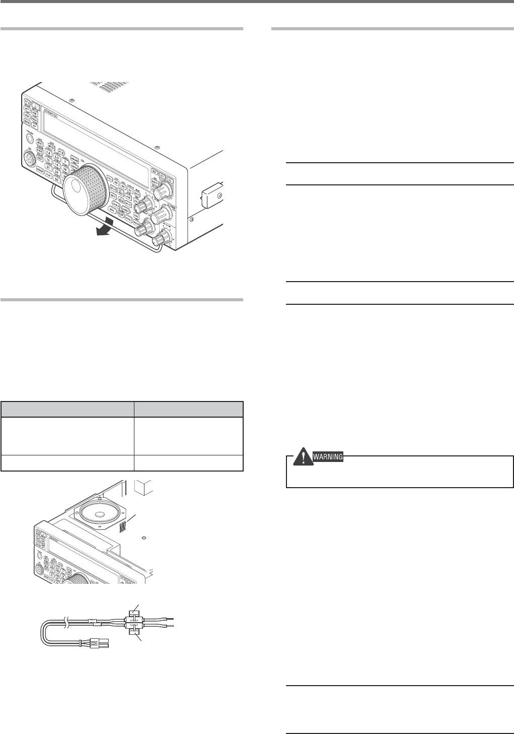
UTILIZING THE BAIL
This transceiver is equipped with a bail so that you
can angle the transceiver. The bail is located on the
bottom of the transceiver. Pull the bail forward to the
limit as shown.
REPLACING FUSES
The following fuses are used in the TS-590SG
transceiver. If a fuse blows, determine the cause
then correct the problem. Only after the problem
has been resolved, replace the blown fuse with a
new one with the specified ratings. If newly installed
fuses continue to blow, disconnect the power plug and
contact a KENWOOD service center or your dealer for
assistance.
Fuse Location Fuse Current Rating
TS-590SG Transceiver
4 A
(for external
antenna tuner)
Supplied DC power cable 25 A
Fuse (4 A)
Fuse (25 A)
Fuse (25 A)
ACCESSORY CONNECTIONS
FRONT PANEL
■ Headphones (PHONES)
Connect monaural or stereo headphones with a
4 to 32 : (normal 8 :) impedance. This jack
accepts a 6.3 mm (1/4") diameter, 2-conductor
(mono) or 3-conductor (stereo) plug. After
connecting the headphones, you will hear no
sound from the internal (or optional external)
Speaker/Microphone (MIC).
Note: Using a high impedance headphone set causes the
volume to be louder.
■ Microphone (MIC)
Connect a microphone with a 250 to 600 :
impedance. Fully insert the connector, then
screw the retaining ring clockwise until secure.
Compatible microphones include the MC-43S,
MC-47, MC-52DM, MC-60A, MC-80, MC-85, and
MC-90.
Note: Do not use the MC-44, MC-44DM, MC-45, MC-45E,
MC-45DM, MC-45DME, or MC-53DM microphones.
REAR PANEL
■ External Speaker (EXT.SP)
On the rear panel of the transceiver, there is an
external speaker jack. If an external speaker is
connected to EXP. SP, the transceiver internal
speaker will mute. Use only external speakers with
an impedance of 4 to 8 : (8 : nominal). This jack
accepts only 3.5 mm (1/8") diameter, 2-conductor
(mono) plugs.
Do not connect headphones to this jack. The high audio
output of this jack could damage your hearing.
■ Keys for CW (PADDLE and KEY)
For CW operation while using the internal
electronic keyer, connect a keyer paddle to the
PADDLE jack.
For CW operation without using the internal
electronic keyer, connect a straight key,
semi-automatic key (bug), electronic keyer,
or the CW keyed output from a Multi mode
Communications Processor (MCP) to the KEY jack.
The PADDLE and KEY jacks mate with a 6.3 mm
(1/4") 3-conductor plug and a 3.5 mm (1/8")
2-conductor plug, respectively. External electronic
keyers or MCPs must use positive keying to be
compatible with this transceiver. Use a shielded
cable between the key and the transceiver.
Note: Due to the functionality of the internal electronic
keyer, you may find it unnecessary to connect both a paddle
and another type of keyer unless you want to use a
PC-based keyer for CW. Read the “ELECTRONIC KEYER”
section {page 33} to become familiar with the internal keyer.
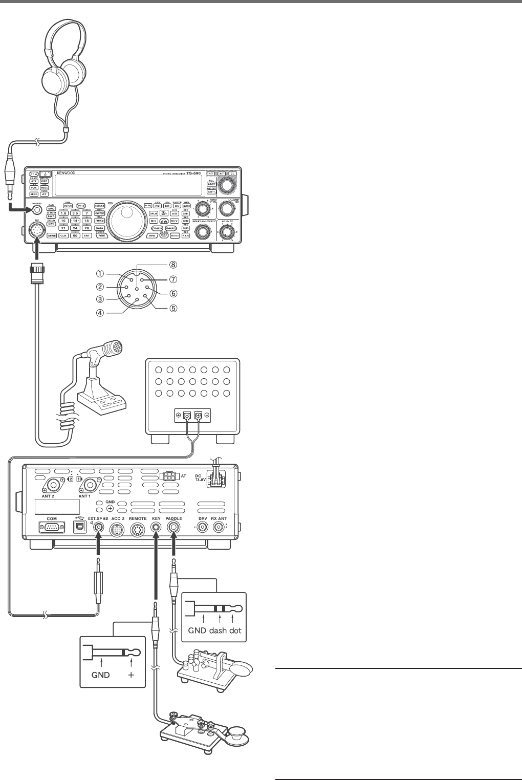
3
INSTALLATION 1
GND (STBY)
GND (MIC)
NC
8 V (10 mA max)
MIC
PTT
DOWN
UP
Microphone
External speaker
MIC connector (Front view)
Headphones
s 0ADDLE
s 3TRAIGHTKEY
s "UGKEY
s %LECTRONICKEYER
s 0#KEYEROUTPUT
Front Panel
Rear Panel
Note:
◆ Do not use a cable exceeding 3 m (9.8 feet) with the
following connectors:
PHONES jack MIC connector
COM connector EXT. SP jack
ACC 2 connector REMOTE connector
KEY jack PADDLE jack
DRV connector
◆ Do not use a cable exceeding 1 m (3.3 feet) with the
following connector:
USB connector
4
2 GETTING ACQUAINTED
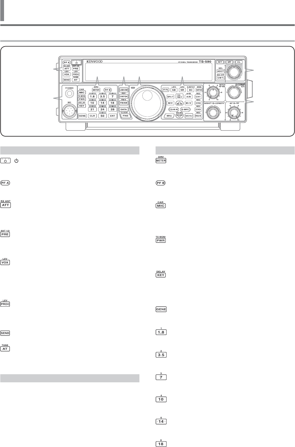
FRONT PANEL
—— C ——
[METER (DRV)]
Press to switch the meter type {page 12}. Press and
hold to turn the Drive Out function ON or OFF {page 50}.
[PF B]
You can assign a function to this Programmable
Function key {page 56}.
[MIC (CAR)]
Press to adjust the microphone gain {page 13}. While
the Speech Processor function is ON, press to adjust
the Speech Processor output level {page 33}. Press
and hold to adjust the carrier level {page 24}.
[PWR (TX MONI)]
Press to adjust the transmission output power
{pages 13, 58}. Press and hold to turn the
transmission signal monitor function ON or OFF
{page 58}.
[KEY (DELAY)]
Press to adjust the internal electronic keyer speed
{page 35}. Press and hold to adjust the VOX delay
time for voice mode {page 33} or Break-in time (Full
Break-in/ Semi Break-in time) for CW mode.
[GENE]
Press to select the general coverage band memory
{page 11}.
[1.8 (1)]
Press to select the 1.8 MHz band memory {page 11}
or enter keypad number 1.
[3.5 (2)]
Press to select the 3.5 MHz band memory {page 11}
or enter keypad number 2.
[7 (3)]
Press to select the 7 MHz band memory {page 11} or
enter keypad number 3.
[10 (4)]
Press to select the 10 MHz band memory {page 11} or
enter keypad number 4.
[14 (5)]
Press to select the 14 MHz band memory {page 11} or
enter keypad number 5.
[18 (6)]
Press to select the 18 MHz band memory {page 11} or
enter keypad number 6.
—— A ——
[ ]
Press and hold to switch the transceiver power ON
and OFF {page 10}.
[PF A]
You can assign a function to this Programmable
Function key {page 56}.
[ATT (RX ANT)]
Press to turn the receiver attenuator ON or OFF
{page 42}. Press and hold to enable or disable the
RX-ANT terminal {page 52}.
[PRE (ANT 1/2)]
Press to turn the pre-amplifier ON or OFF {page 40}.
Press and hold to select either ANT 1 or ANT 2
{page 52}.
[VOX (LEV)]
In voice mode, press to turn the VOX (Voice-Operated
Transmit) function ON or OFF {page 32}. In CW
mode, press to turn the Break-in function ON or OFF
{page 35}. Press and hold to adjust the microphone
input gain for VOX operation.
[PROC (LEV)]
Press to turn the Speech Processor ON or OFF
{page 33}. Press and hold to adjust the Speech
Processor input level.
[SEND]
Press to turn transmission ON or OFF.
[AT (TUNE)]
Press to turn the internal antenna tuner ON or
OFF {page 50}. Press and hold to start tuning the
automatic antenna tuner.
—— B ——
PHONES jack
Mate with a 6.3 mm (1/4") diameter, 2-conductor
(mono) or 3-conductor (stereo) plug for connecting a
set of headphones {page 2}.
MIC connector
Connect a microphone to this connector {page 2}.
A
B
CDFEG
H
5
GETTING ACQUAINTED 2
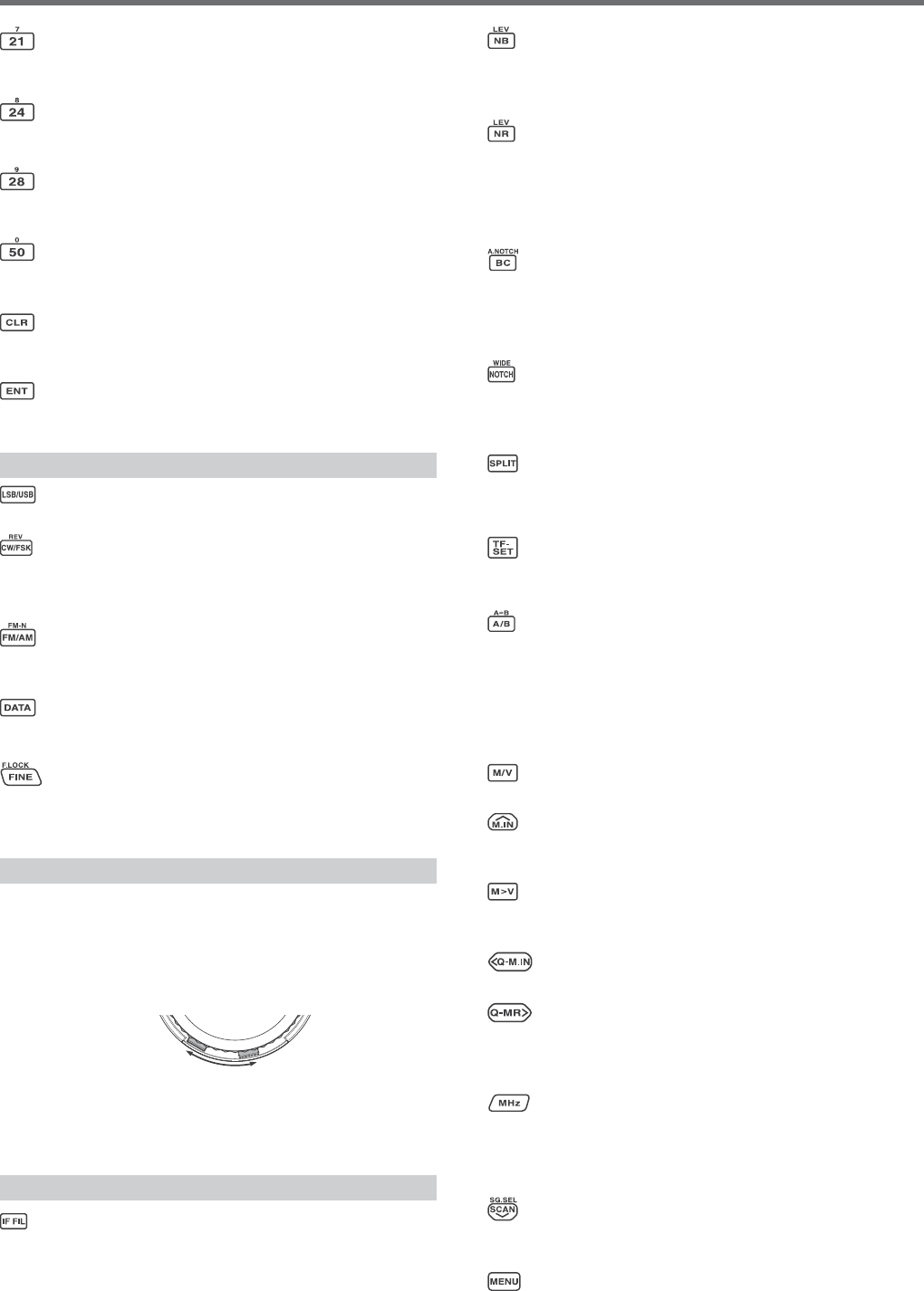
[21 (7)]
Press to select the 21 MHz band memory {page 11} or
enter keypad number 7.
[24 (8)]
Press to select the 24 MHz band memory {page 11} or
enter keypad number 8.
[28 (9)]
Press to select the 28 MHz band memory {page 11} or
enter keypad number 9.
[50 (0)]
Press to select the 50 MHz band memory {page 11} or
enter keypad number 0.
[CLR]
Press to exit from, abort, or reset various functions.
Press and hold to clear a memory channel {page 46}.
[ENT]
Press to enter your desired frequency using the
10-key keypad {page 30}.
—— D ——
[LSB/USB]
Press to select LSB or USB mode {page 11}.
[CW/FSK (REV)]
Press to select CW or FSK mode {page 11}. Press
and hold to select a sideband (CW/ CW-R or FSK/
FSK-R).
[FM/AM (FM-N)]
Press to select FM or AM mode {page 11}. Press and
hold to select Narrow FM mode.
[DATA]
Press to select a Data mode (LSB/ LSB-DATA, USB/
USB-DATA, FM/ FM-DATA, or AM-DATA) {page 11}.
[FINE (F.LOCK)]
Press to activate the Fine tuning function to allow
more precise tuning {page 31}. Press and hold to
activate the Frequency Lock function {page 55}.
—— E ——
Central (Tuning) control
Turn to select the desired frequency {page 12}. Use
the convenient finger-tip cavity for continuous tuning.
Slide the lever underneath the Tuning control to the
left or right to adjust the torque level of the control.
Left makes the control light and right makes it heavy.
light heavy
TX-RX LED
Lights red while transmitting and green when the
squelch opens while receiving.
—— F ——
[IF FIL]
Press to toggle between IF Filter A and IF Filter B
{page 41}. You can adjust the filter bandwidth using
the LO/WIDTH and HI/SHIFT controls. Press and
hold [IF FIL] to momentarily display each setting value
of the current DSP filter DSP filter bandwidth {page
38}.
[NB (LEV)]
Press to cycle through Noise Blanker 1, Noise Blanker
2, and OFF. Press and hold to adjust the Noise
Blanker level {page 42}.
[NR (LEV)]
Press to cycle through the DSP Noise Reduction
types: NR1, NR2, or OFF {page 41}. When the Noise
Reduction function is turned ON, press and hold
to change the parameters of the Noise Reduction
function {page 40}.
[BC (A.NOTCH)]
Press to select the DSP Beat Cancel function, BC1
(Beat Cancel 1), BC2 (Beat Cancel 2) or OFF
{page 41}. Press and hold to toggle the Auto
Notch Filter ON and OFF {page 41}.
[NOTCH (WIDE)]
Press to toggle the IF Notch Filter ON or OFF
{page 41}. Press and hold to set up the IF Notch
bandwidth {page 41}.
[SPLIT]
Press to enter split-frequency operation, allowing
you to use different transmission and reception
frequencies {page 25}.
[TF-SET]
During split-frequency operation, press to monitor or
change your transmit frequency {page 26}.
[A/B (A=B)]
Press to select either VFO A or VFO B {page 10}.
Press and hold to duplicate the data in the current
VFO to the other VFO {page 27}. While in Menu
mode, press to select Menu A or Menu B. While in
Program Memory Channel mode, press to recall the
start or end frequency.
[M/V]
Press to toggle between Memory and VFO modes.
[M.IN]
Press to enter Memory Scroll mode and to store data
to a Memory channel {page 43}.
[M>V]
Press to transfer the current Memory Channel
contents to the VFO.
[Q-M.IN]
Press to store data to the Quick Memory {page 46}.
[Q-MR]
Press to recall data from the Quick Memory {page 47},
while in VFO mode. Press to enter Memory Name
Edit mode, while in Memory Channel mode {page 46}.
[MHz]
Press to turn the MHz Up/ Down function ON or OFF.
The MHz digit increases or decreases when you turn
the MULTI/CH control. In Menu mode, press to turn
the Quick Menu ON or OFF {page 14}.
[SCAN (SG.SEL)]
Press to start or stop the Scan function {page 48}.
Press and hold to select a Scan group {page 51}.
[MENU]
Press to enter Menu mode {page 14}.
6
2 GETTING ACQUAINTED
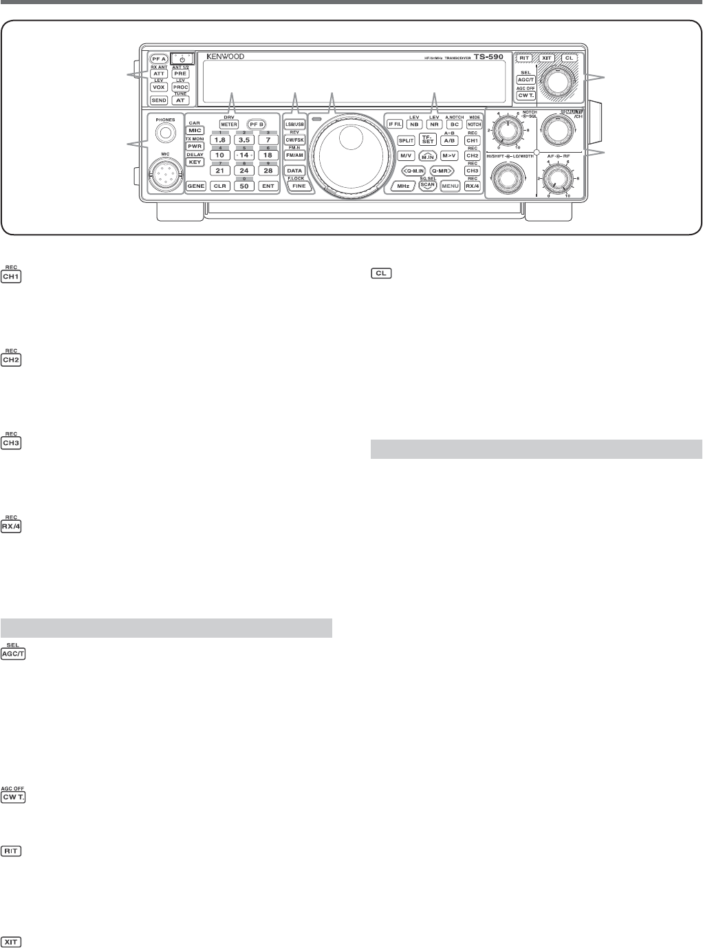
[CH1 (REC)]
Press to play back a CW {page 37} or voice message
(requires VGS-1 option) {page 62}. Press and hold to
record a CW {page 36} or voice message (requires
VGS-1 option) {page 62}.
[CH2 (REC)]
Press to play back a CW {page 37} or voice message
(requires VGS-1 option) {page 62}. Press and hold to
record a CW {page 36} or voice message (requires
VGS-1 option) {page 62}.
[CH3 (REC)]
Press to play back a CW {page 37} or voice message
(requires VGS-1 option) {page 62}. Press and hold to
record a CW {page 36} or voice message (requires
VGS-1 option) {page 62}.
[RX/4 (REC)]
Press to play back a CW {page 37} or voice message
(requires VGS-1 option) {page 62}, or the constantly
recorded signal (requires VGS-1 option) {page 63}.
Press and hold to activate the constant recorder
(requires VGS-1 option) {page 63}.
—— G ——
[AGC/T (SEL)]
Press to toggle the fast or slow response time for
the Automatic Gain Control (AGC) {page 31}. In FM
mode, press to cycle through the Tone settings: Tone,
CTCSS, CTCSSx, or OFF {page 28}. When Tone is
activated in FM mode, press and hold to select a Tone
frequency {page 28}. When CTCSS is activated in FM
mode, press and hold to select a CTCSS frequency
{page 29}.
[CW T. (AGC OFF)]
Press to start CW auto tuning {page 23}. Press and
hold to turn AGC OFF {page 31}.
[RIT]
Press to turn the RIT (Receive Incremental Tuning)
function ON or OFF {page 31}.
You can assign a function to this Programmable
Function key {page 56}.
[XIT]
Press to turn the XIT (Transmit Incremental Tuning)
function ON or OFF {page 33}.
You can assign a function to this Programmable
Function key {page 56}.
[CL]
Press to clear the RIT/ XIT frequency to zero
{pages 31, 33}.
You can assign a function to this Programmable
Function key {page 56}.
RIT/ XIT control
When the RIT/ XIT function is ON, turn to adjust
the offset frequency. The RIT/ XIT offset frequency
appears on the sub-display {pages 29, 31}. While
scanning, turn to adjust the scan speed.
—— H ——
SQL control
Turn to select the desired squelch level {page 12}.
NOTCH control
Turn to select the desired Notch frequency {page 41}.
MULTI/CH control
In VFO mode, rotate to step the operating frequency
up or down {page 30}. In Memory Channel mode,
rotate to select a Memory Channel {page 43}.
Also, used for selecting Menu numbers when
accessing the Menu mode {page 14} and for various
configurations. The MULTI/CH LED lights when the
MULTI/CH control is not being used to adjust the step
frequency.
You can assign a function to this Programmable
Function key {page 56}.
HI/SHIFT control
Rotate to adjust the DSP filter bandwidth (high-cut) or
to adjust the DSP filter bandwidth (filter band shift)
{page 40}.
LO/WIDTH control
Rotate to adjust the DSP filter bandwidth (high-cut or
shift) {page 40}.
AF control
Turn to adjust the AF gain level {page 10}.
RF control
Turn to adjust the RF gain level {page 10}.
A
B
CDFEG
H
7
GETTING ACQUAINTED 2
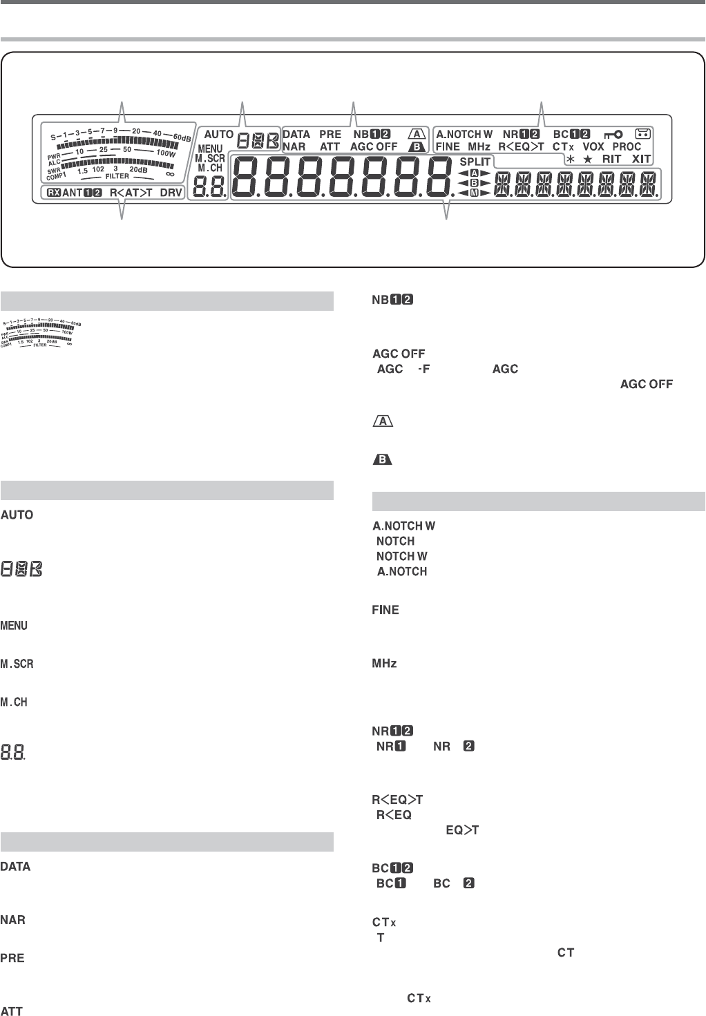
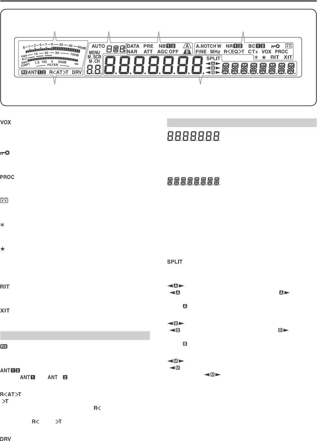
—— A ——
While receiving, the meter serves as an S-meter to
measure and display the received signal strength.
While transmitting, it serves as a power meter plus an
ALC meter, an SWR meter, or a Speech Processor
compression meter. The Peak Hold function holds
each reading for approximately half a second. While
adjusting the IF filter bandwidth, the meter displays an
adjustment state.
—— B ——
Appears when the Auto Mode function is ON and
while in Auto Mode frequency setup {page 53}.
Displays the operating mode (USB, LSB, FM, AM,
CW, CWR, FSK, or FSR) {page 11}.
Appears while in Menu mode {page 14}.
Appears while in Memory Scroll mode {page 44}.
Appears while in Memory Channel mode or Memory
Scroll mode {page 44}.
In normal operating mode and various configuration
modes, it displays the Memory Channel number,
Quick Memory number, and entry log number. In
Menu mode, it displays the Menu No.
—— C ——
Appears while in Data mode {page 11} and while in
CW Morse Decoder mode {page 38}.
Appears while in narrow FM mode {page 11}.
Appears when the receiver pre-amplifier is ON {page
42}.
Appears when the receiver’s attenuator is ON {page
42}.
Appears when the Noise Blanker 1 or 2 is ON
{page 42}.
“” (fast) or “ ” (slow) appears when the
Automatic Gain Control function is ON. “ ”
appears when the AGC is OFF {page 31}.
Appears when IF filter A is selected {page 41}.
Appears when IF filter B is selected {page 41}.
—— D ——
“” appears when manual notch is set to Normal.
“” appears when Manual Notch is set to Wide.
“” appears when Auto Notch is selected {page
41}.
Appears when the Fine Tuning function is ON {page
31}.
Appears when the MHz Step function is ON {page 30}.
Also appears when the Quick Menu function is ON
{page 14}.
“” or “ ” appears, depending on whether
DSP Noise Reduction 1 or Noise Reduction 2 is
selected {page 41}.
“” appears when the RX Equalizer function is ON
{page 57}. “ ” appears when the TX Equalizer
function is ON {page 34}.
“” or “ ” appears, when you select the DSP
Beat Cancel 1 or Beat Cancel 2 {page 41}.
“” appears when the Tone function is ON {page 27},
and blinks during Tone scan. “ ” appears when the
CTCSS (Continuous Tone Coded Squelch System)
function is ON, and blinks during CTCSS scan {page
28}. “ ” appears when the Cross Tone function is
ON {page 29}.
LCD DISPLAY
ABC D
EF
8
2 GETTING ACQUAINTED
Appears when the VOX (Voice Operated Transmission)
function is ON or the Break-in function is ON for CW
mode {page 32}.
Appears when the Frequency Lock function is ON
{page 55}.
Appears when the Speech Processor function is ON
{page 33}.
Appears when the constant recording function is ON
{page 63}.
Appears when the Antenna output is enabled (DRV
connector) {page 52}.
Appears when the selected Menu No. is in the
Quick Menu list {page 14}. It also appears when the
transceiver is scanning the frequencies between the
slow down frequency points {page 49}.
Appears when Receive Incremental Tuning function is
ON {page 31}.
Appears when Transmit Incremental Tuning function is
ON {page 33}.
—— E ——
Appears when the RX ANT terminal is enabled {page
52}.
Either “ ” or “ ” appears, depending on
which antenna connector is selected {page 52}.
“ ”
appears while the internal antenna tuner
{page 61} is in-line for operation.
“ ” appears while
receiving when the internal antenna tuner is in-line for
operation.
“ ” and “ ” blink while tuning is in progress
{page 52}
.
Appears when the Drive output is enabled (DRV
connector) {page 52}.
—— F ——
(Main DIsplay)
In normal operating mode and various configuration
modes, it displays the transceiver operating frequency.
In Menu mode, it displays the various menus, and in
Adjustment mode, it displays the adjustment values.
(Sub-display)
When recalling a memory channel, it displays
the Memory Channel name (if one has been
programmed). During split frequency operation, it
displays the frequency. When the following indications
occur simultaneously, information is displayed in the
following order: RIT/XIT frequency, Split frequency,
Memory Name. In Menu mode, it displays a menu
title. In other modes, it displays the configuration
parameters.
Appears when the split-frequency operation is ON
{page 25}.
“” appears while VFO A is selected. “ ” appears
while transmitting on a split channel in VFO A {page
10}. “ ” appears while Menu A is being accessed in
Menu mode {page 14}.
“ ” appears while VFO B is selected. “ ” appears
while transmitting on a split channel in VFO B {page
10}. “ ” appears while Menu B is being accessed in
Menu mode {page 14}.
“” appears while a simplex memory channel
is selected. “ ” appears while a split memory
channel is selected {page 43}.
ABC D
EF
9
GETTING ACQUAINTED 2
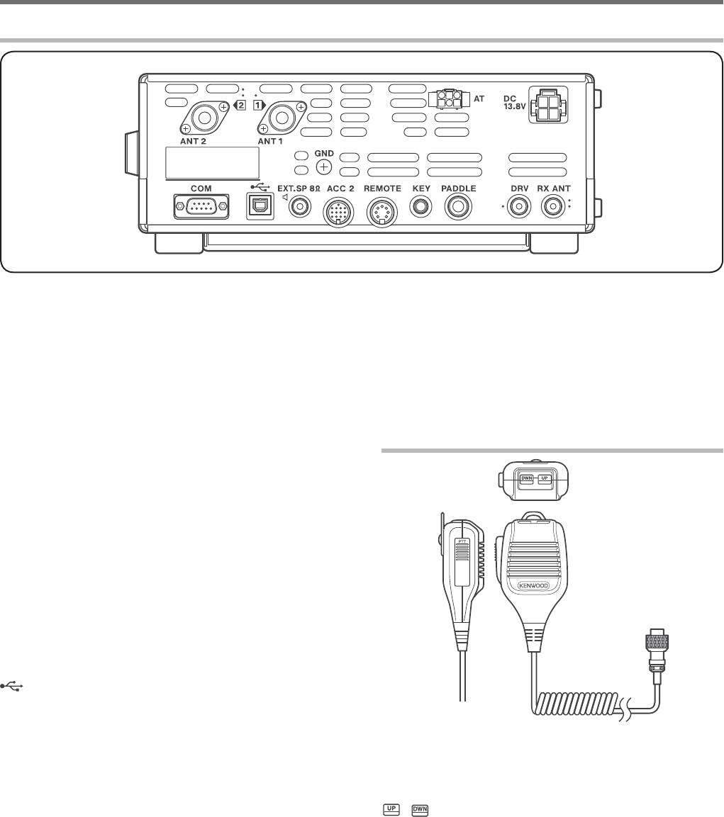
ANT 1 and ANT 2 connectors
Connect your primary HF/ 50 MHz antenna to ANT 1
connector. If you are using 2 antennas for the HF/
50 MHz band, connect the secondary antenna to the
ANT 2 connector {page 1}.
GND post
Connect a heavy gauge wire or copper strap between
the ground post and the nearest earth ground {page 1}.
AT connector
Mates with the connector from the cable supplied with
the AT-300 external antenna tuner {pages 70, 73}.
Refer to the instruction manual supplied with the tuner
for more information.
DC 13.8 V connector
Connect a regulated 13.8 V DC power source to this
connector {page 1}. Use the DC cable supplied with
the transceiver.
COM connector
Mates with a DB-9 female connector for connecting a
computer or compatible transceiver {pages 60, 69}.
Also used with the Quick Data Transfer function {page
59} and DX PacketCluster Tune function {page 67}.
(USB) connector
Mates with a USB connector for connecting a
computer via one of its USB ports {pages 60}.
EXT.SP 8: jack
Mate with a 3.5 mm (1/8"), 2-conductor (mono) plug
for connecting an external speaker {page 2}.
ACC 2 connector
Mates with a 13-pin male DIN connector for
connecting various accessory equipment, such as
an external TNC/ MCP or a RTTY terminal
{page 69}.
REMOTE connector
Mates with a 7-pin male DIN connector for connecting
an HF/ 50 MHz linear amplifier {page 65, 68}.
KEY and PADDLE jacks
The KEY jack mates with a 3.5 mm (1/8") 2-conductor
plug for connecting an external key for CW operation.
The PADDLE jack mates with a 6.3 mm (1/4")
3-conductor plug for connecting a keyer paddle to
the internal electronic keyer. Refer to “Keys for CW
(PADDLE and KEY)” {page 2} before using these jacks.
REAR PANEL
DRV connector
Connect a drive device to this RCA connector {page
52}.
RX ANT connector
Connect a separate receive-only antenna for HF low
bands to this RCA connector {page 52}.
MICROPHONE
PTT (Push-to-Talk) switch
The transceiver is placed in Transmission mode when
this non-locking switch is held down. Releasing the
switch returns the transceiver to Reception mode.
/ Mic [UP]/ [DWN]
Use these keys to step the VFO frequency, Memory
Channels, or Menu selections up and down.
Press and hold these keys to continuously change the
settings.
You can also change the operational function of these
keys {page 56}
10
3 OPERATING BASICS
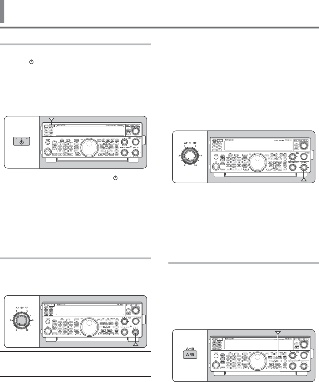
SWITCHING POWER ON/ OFF
1 Switch the DC power supply ON.
2 Press [] to switch the transceiver ON.
s )FYOUHOLDTHEPOWERSWITCHFORMORETHAN
APPROXIMATELYSECONDSTHETRANSCEIVERWILL
switch back OFF.
s 5PONPOWERUPh(%,,/vAPPEARSONTHEMAIN
DISPLAYFOLLOWEDBYTHECURRENTFREQUENCYAND
OTHERINDICATORS
3 4OSWITCHTHETRANSCEIVER/&&PRESS[ ] again.
4 Switch the DC power supply OFF.
s 9OUMAYSKIPSTEP3!FTERSWITCHINGTHE
TRANSCEIVER/.YOUCANSWITCHIT/&&OR/.
USINGONLYTHEPOWERSWITCHOFTHE$#POWER
SUPPLY4HETRANSCEIVERREMEMBERSTHEPOWER
switch position when the DC power source is
SWITCHED/&&
ADJUSTING THE VOLUME
AF (AUDIO FREQUENCY) GAIN
Turn the AFCONTROLCLOCKWISETOINCREASETHEAUDIO
LEVELANDCOUNTERCLOCKWISETODECREASEIT
Note:4HEPOSITIONOFTHEAFCONTROLDOESNOTAFFECTTHEVOLUME
OFBEEPSCAUSEDBYPRESSINGKEYSNORTHE#748SIDETONE4HE
AUDIOLEVELFOR$IGITALMODEOPERATIONISALSOINDEPENDENTOFTHE
AF control setting.
RF (RADIO FREQUENCY) GAIN
4HE2&GAINISNORMALLYCONlGUREDTOTHEMAXIMUM
LEVELREGARDLESSOFTHEOPERATINGMODES4HE
TRANSCEIVERHASBEENCONlGUREDTOTHEMAXIMUM
LEVELATTHEFACTORY(OWEVERYOUMAYDECREASETHE
RF gain slightly when you have trouble hearing the
DESIREDSIGNALDUETOEXCESSIVEATMOSPHERICNOISEOR
INTERFERENCEFROMOTHERSTATIONS
&IRSTTAKENOTEOFTHEPEAK3METERREADINGOF
THEDESIREDSIGNAL4HENTURNTHERF control
COUNTERCLOCKWISEUNTILTHE3METERREADSTHEPEAK
VALUETHATYOUNOTED
s 3IGNALSTHATAREWEAKERTHANTHISLEVELWILLBE
ATTENUATEDANDRECEPTIONOFTHESTATIONWILLBECOME
easier.
$EPENDINGONTHETYPEANDGAINOFYOURANTENNAAND
THECONDITIONOFTHEBANDADJUSTTHE2&GAIN7HEN
USING&-MODEALWAYSADJUSTTHE2&GAINTOTHE
MAXIMUMLEVEL
SELECTING VFO A OR VFO B
4WO6&/SAREAVAILABLEFORCONTROLLINGTHEFREQUENCY
ONTHETRANSCEIVER%ACH6&/6&/!AND6&/"
WORKSINDEPENDENTLYSOTHATADIFFERENTFREQUENCYAND
MODECANBESELECTED&OREXAMPLEWHEN30,)4
OPERATIONISACTIVATED6&/!ISUSEDFORRECEPTION
AND6&/"ISUSEDFORTRANSMISSION4HEOPPOSITE
COMBINATIONISALSOPOSSIBLE
Press [A/B (A=B)] TOTOGGLEBETWEEN6&/!AND"
11
3 OPERATING BASICS
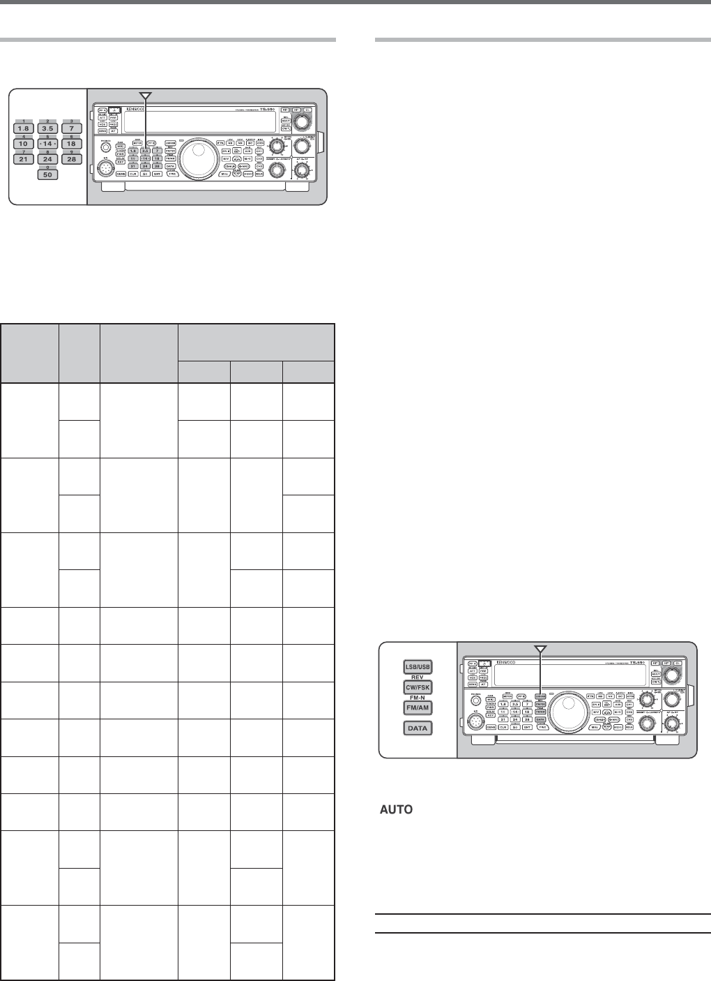
SELECTING A BAND
Press [1.8 (1)] ~ [50 (0)] or [GENE] to select your
DESIREDBAND
s 0RESSEACHKEYTOCYCLETHROUGHTHEDEFAULT
settings as shown in the table below.
s %ACHSETTINGCANBEMODIlEDWITHYOURPERSONAL
PREFERENCEFORFREQUENCYANDMODE!FTER
MODIFYINGTHESETTINGPRESSINGTHEKEYAGAINWILL
save that setting.
Key
Type
Frequency
Range
(MHz)
Default Setting (MHz)/
Mode
123
[1.8 (1)]
K
^
1.8/
#7
#7
1.84/
#7
%
#7
1.84/
#7
1.81/
#7
[3.5 (2)]
K
^
,3"
,3"
,3"
%
,3"
[7 (3)]
K
^
,3"
,3"
,3"
%
,3"
,3"
[10 (4)]
All ^ 10.1/
#7
#7
10.14/
#7
[14 (5)]
All
^
14.0/
53"
14.1/
53"
53"
[18 (6)]
All ^
18.068/
53"
18.11/
53"
53"
[21 (7)]
All
^
53"
53"
53"
[24 (8)]
All ^
53"
53"
53"
[28 (9)]
All ^
53"
53"
FM
[50 (0)]
K
^
53"
53"
FM
%
53"
[GENE]
K
^
#7
53"
53"
%
53"
SELECTING A MODE
0RESSONEOFTHEFOLLOWINGKEYSTOSELECTYOURDESIRED
MODESET[LSB/USB][CW/FSK (REV)]OR[FM/AM
(FM-N)].
[LSB/USB]
0RESSTOSELECT,3"OR53"MODE0RESSAGAINTO
TOGGLEBETWEEN,3"AND53"MODE
7HILEIN,3"MODEPRESS[DATA] to toggle between
,3"AND,3"$!4!MODE,IKEWISEWHILEIN53"
MODEPRESS[DATA]TOTOGGLEBETWEEN53"AND53"
$!4!MODE
!DDITIONALLYWHILEIN,3"$!4!OR53"$!4!MODE
you can press [LSB/USB]TOTOGGLEBETWEEN,3"
$!4!AND53"$!4!MODE
[CW/FSK (REV)]
0RESSTOSELECT#7OR&3+MODE0RESSAGAINTO
TOGGLEBETWEEN#7AND&3+MODE
7HILEIN#7MODEPRESSANDHOLD[CW/FSK (REV)]
TOTOGGLEBETWEEN#7AND#72MODE,IKEWISE
WHILEIN&3+MODEPRESSANDHOLD[CW/FSK (REV] to
TOGGLEBETWEEN&3+AND&3+2MODE
!DDITIONALLYWHILEIN#72OR&3+2MODEYOUCAN
press [CW/FSK (REV)]TOTOGGLEBETWEEN#72AND
&3+2MODE
[FM/AM (FM-N)]
0RESSTOSELECT&-OR!-MODE0RESSAGAINTO
TOGGLEBETWEEN&-AND!-MODE
7HILEIN&-MODEPRESSANDHOLD[FM/AM (FM-N)]
TOTOGGLEBETWEEN&-AND&-.!2MODEORPRESS
[DATA]TOTOGGLEBETWEEN&-AND&-$!4!MODE
!DDITIONALLYWHILEIN&-.!2MODEPRESS[DATA] to
TOGGLEBETWEEN&-.!2AND&-.!2$!4!MODE
ANDWHILEIN&-$!4!MODEPRESSANDHOLD[FM/AM
(FM-N)]TOTOGGLEBETWEEN&-$!4!AND&-.!2
$!4!MODE
7HILEIN!-MODEPRESS[DATA] to toggle between
!-AND!-$!4!MODE
Access Menu No. then press [M.IN]TOSELECThONv
TOTURNTHE!UTO-ODESELECTION/.7HENITIS/.
hvAPPEARS!SADEFAULTIFYOUCHANGETHE
FREQUENCYABOVEORBELOW-(ZTHETRANSCEIVER
AUTOMATICALLYSWITCHESMODES,3"FORFREQUENCIES
UNDER-(ZAND53"FORFREQUENCIES-(ZAND
OVER9OUCANFURTHERADDTHEFREQUENCYBORDERSTOTHE
!UTO-ODESELECTION[PAGE}.
Note:4HELASTUSEDMODEISSTOREDPEREACHBANDKEY
3 OPERATING BASICS
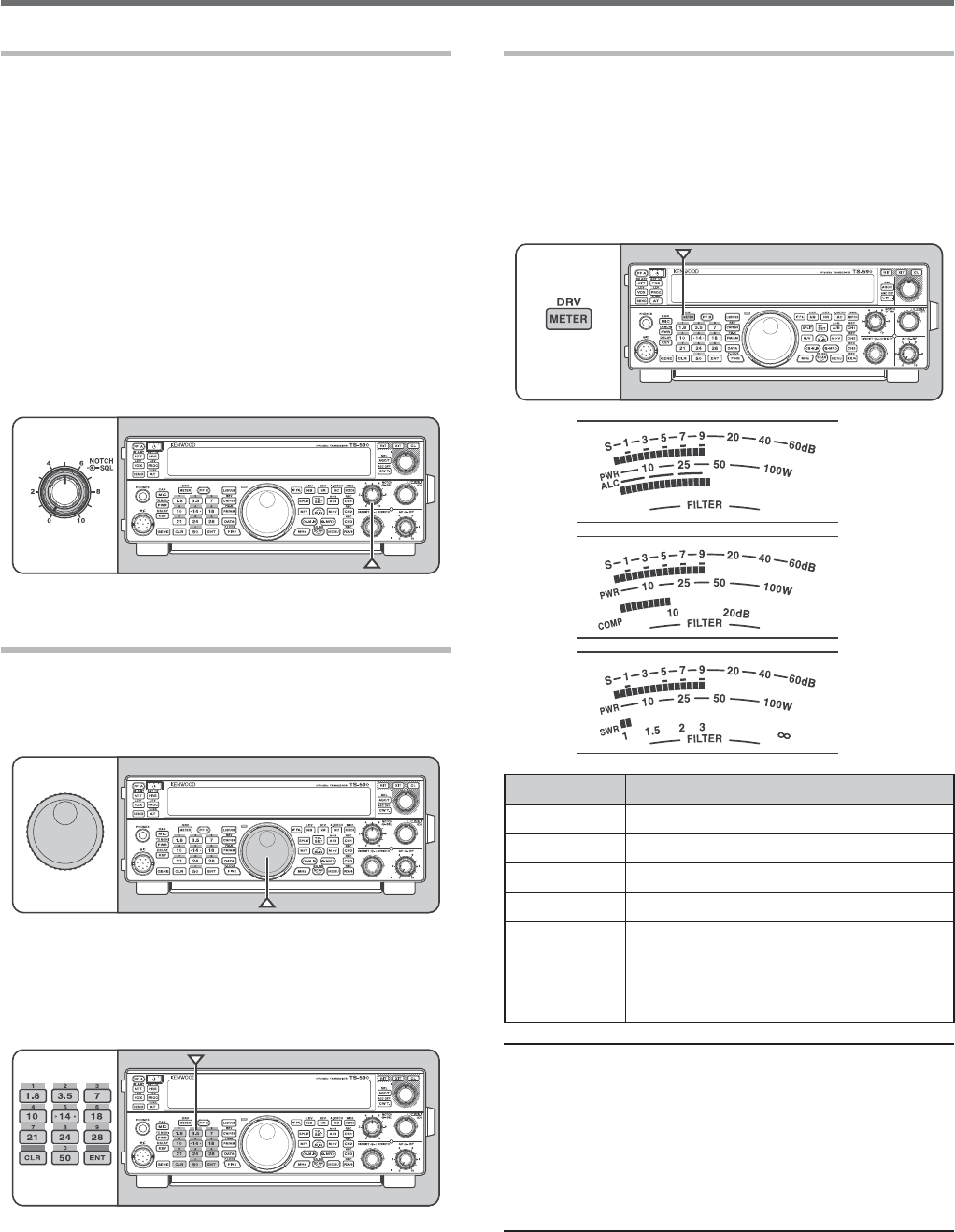
MULTI-FUNCTION METER
4HEMULTIFUNCTIONMETERMEASURESTHEPARAMETERS
INTHETABLEBELOW4HE3METERAND&),4%2SCALES
APPEARSWHENTHETRANSCEIVERISINRECEIVEMODEAND
THE072METERAPPEARSWHENITISINTRANSMITMODE
%ACHPRESSOF [METER (DRV)] cycles between the
!,##/-0AND372METERS0EAKREADINGSFORTHE
3METER!,#372#/-0AND072FUNCTIONSARE
HELDMOMENTARILY
ALC
COMP
SWR
Meter Name Parameters Measured
S3TRENGTHOFRECEIVEDSIGNALS
072 4RANSMISSIONOUTPUTPOWER
!,# !UTOMATICLEVELCONTROLSTATUS
372 !NTENNASYSTEMSTANDINGWAVERATIO
COMP
3PEECHCOMPRESSIONLEVELWHEN
using the Speech Processor
[PAGE}
&),4%2 )&lLTERWIDTH[PAGE40}
Note:
◆ 4HE#/-0METERFUNCTIONSONLYWHENTHE3PEECH
0ROCESSORIS/.FOR33"&-OR!-MODE
◆ 0EAK(OLDREADINGSCANNOTBEDEACTIVATED
◆ 4HE3METERRESPONDSDIFFERENTLYIN&-MODECOMPAREDTO
OTHERMODES4HISISNOTAMALFUNCTION
◆ 7HENYOUTURN/&&THE3PEECH0ROCESSORWHILEUSINGTHE
#/-0METERTHE#/-0METERCHANGESTOTHE!,#METER
7HENYOUTURN/.THE3PEECH0ROCESSORAGAINTHE!,#
METERRETURNSTOTHE#/-0METER
ADJUSTING THE SQUELCH
4HEPURPOSEOFTHE3QUELCHISTOMUTETHESPEAKER
WHENNOSIGNALSAREPRESENT7ITHTHESQUELCHLEVEL
CORRECTLYSETYOUWILLHEARSOUNDONLYWHILEACTUALLY
RECEIVINGSIGNALS4HEHIGHERTHESELECTEDSQUELCH
LEVELTHESTRONGERTHESIGNALSMUSTBETORECEIVE4HE
APPROPRIATESQUELCHLEVELDEPENDSONTHEAMBIENT2&
NOISECONDITIONS
Turn the SQL control when there are no signals
PRESENTTOSELECTTHESQUELCHLEVELATWHICHTHE
BACKGROUNDNOISEISJUSTELIMINATEDTHEGREEN4828
,%$WILLTURNOFF-ANYHAMOPERATORSPREFERLEAVING
the SQLCONTROLFULLYCOUNTERCLOCKWISEUNLESS
OPERATINGONAFULLCARRIERMODESUCHAS&-4HE
SQUELCHLEVELFORTHETRANSCEIVERISPRESETATTHEFACTORY
TOAPPROXIMATELYTHEOCLOCKPOSITIONFOR&-AND
OCLOCKFOR33"AND!-
TUNING A FREQUENCY
Turn the Tuning control clockwise or press Mic [UP
TOINCREASETHEFREQUENCY4URNTHETuning control
counterclockwise or press Mic [DWN]TODECREASETHE
FREQUENCY
9OUMAYPREFERDIRECTLYENTERINGAFREQUENCYUSING
THENUMERICKEYPADIFTHEDESIREDFREQUENCYISFAR
FROMTHECURRENTFREQUENCY0RESS [ENT] then press
THENUMERICKEYSASNECESSARY&ORDETAILSREFERTO
h$IRECT&REQUENCY%NTRYv[PAGE}.
OPERATING BASICS 3
TRANSMITTING
&ORVOICECOMMUNICATIONSPRESSANDHOLD-IC[PTT]
ANDSPEAKINTOTHEMICROPHONEINYOURNORMALVOICE
7HENYOUlNISHSPEAKINGRELEASE-IC[PTT] to
receive.
4OTRANSMIT#7PRESS[VOX (REV)]TOTURNTHE"REAK
INFUNCTION/.h vAPPEARS#LOSETHEKEYORKEYER
PADDLE#ONNECTAKEYORKEYERPADDLE[PAGE]THEN
SELECT#7USING [CW/FSK (REV)].
&ORADETAILEDEXPLANATIONONTRANSMITTINGREFERTO
h"!3)##/--5.)#!4)/.3vBEGINNINGONPAGE.
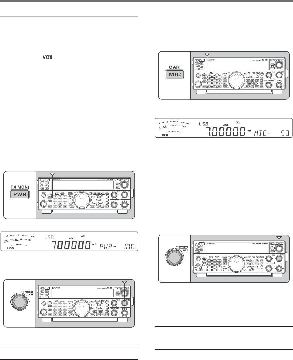
SELECTING TRANSMISSION POWER
)TISWISETOSELECTALOWERTRANSMISSIONPOWERIF
COMMUNICATIONISSTILLRELIABLE4HISLOWERSTHERISKOF
INTERFERINGWITHOTHERSONTHEBAND7HENOPERATING
FROMBATTERYPOWERSELECTINGALOWERTRANSMISSION
POWERALLOWSYOUMOREOPERATINGTIMEBEFORE
recharging is necessary. This transceiver allows
YOUTOCHANGETHETRANSMISSIONPOWEREVENWHILE
TRANSMITTING
1 Press [PWR (TX MONI)].
s 4HECURRENTTRANSMISSIONPOWERAPPEARS
2 Turn the MULTI/CH control counterclockwise to
REDUCETHEPOWERORCLOCKWISETOINCREASETHE
power.
3 Press [PWR (TX MONI)] or [CLR]TOCOMPLETETHE
setting.
Note: 9OUCANACCESS-ENU.OANDSELECThONvTOCHANGE
THESTEPSIZEFROM7TO7[PAGE}.
MICROPHONE GAIN
4HEMICROPHONEGAINMUSTBEADJUSTEDWHEN33"
OR!-MODEISSELECTEDWITHOUTUSINGTHESPEECH
PROCESSOR[PAGES}.
1 Press [MIC (CAR)].
s 4HECURRENTMICROPHONEGAINLEVELAPPEARS
4HERANGEISFROMTOWITHADEFAULTOF
2 0RESSANDHOLD-IC[PTT].
s 4HE4828,%$LIGHTSRED
3 33"7HILESPEAKINGINTOTHEMICROPHONEADJUST
the MULTI/CHCONTROLSOTHATTHE!,#METER
REmECTSYOURVOICELEVELBUTDOESNOTEXCEEDTHE
!,#LIMIT
!-7HILESPEAKINGINTOTHEMICROPHONEADJUST
the MULTI/CHCONTROLSOTHATTHEPOWERMETER
slightly reflects your voice level.
&-!CCESS-ENU.OANDSELECThv.ORMAL
hv-EDIUMORhv(IGHFORTHEMICROPHONEGAIN
IFNECESSARY[PAGE}.
4 Release Mic [PTT] to receive.
s 4HE4828,%$LIGHTSGREENORTURNSOFF
DEPENDINGONTHESQL control setting.
5 Press [MIC (CAR)] or [CLR] to exit the Microphone
GAINADJUSTMENT
Note: 7HENUSINGTHE-#MICROPHONEIN&-MODESELECT
hv(IGHFORTHEMICROPHONEGAIN4HEMICROPHONESENSITIVITY
ISLOWIN&-MODE4HISMAYCAUSEINSUFlCIENTMODULATION&OR
OTHERMICROPHONESSELECTEITHERhv.ORMALORhv-EDIUM
14
4 MENU SETUP
WHAT IS A MENU?
Many functions on this transceiver are selected or
configured via a software-controlled Menu, rather than
through the physical controls of the transceiver. Once
familiar with the Menu system, you will appreciate
the versatility it offers. You can customize the various
timings, settings, and programming functions on this
transceiver to meet your needs without using many
controls and switches.
MENU A/ MENU B
This transceiver has 2 menus: Menu A and Menu B.
These menus contain identical functions and can be
configured independently. The transceiver, therefore,
allows you to switch between 2 different environments
quickly and easily. For example, you can configure
Menu A for DXing and contesting while Menu B is
for relaxed local ragchewing. By switching from
Menu A to Menu B, you can instantly change the
Menu configuration and key assignment to suit your
current operating style. Or, 2 operators may share
a single transceiver by dedicating one Menu to each
operator. Both operators can always enjoy their own
configuration.
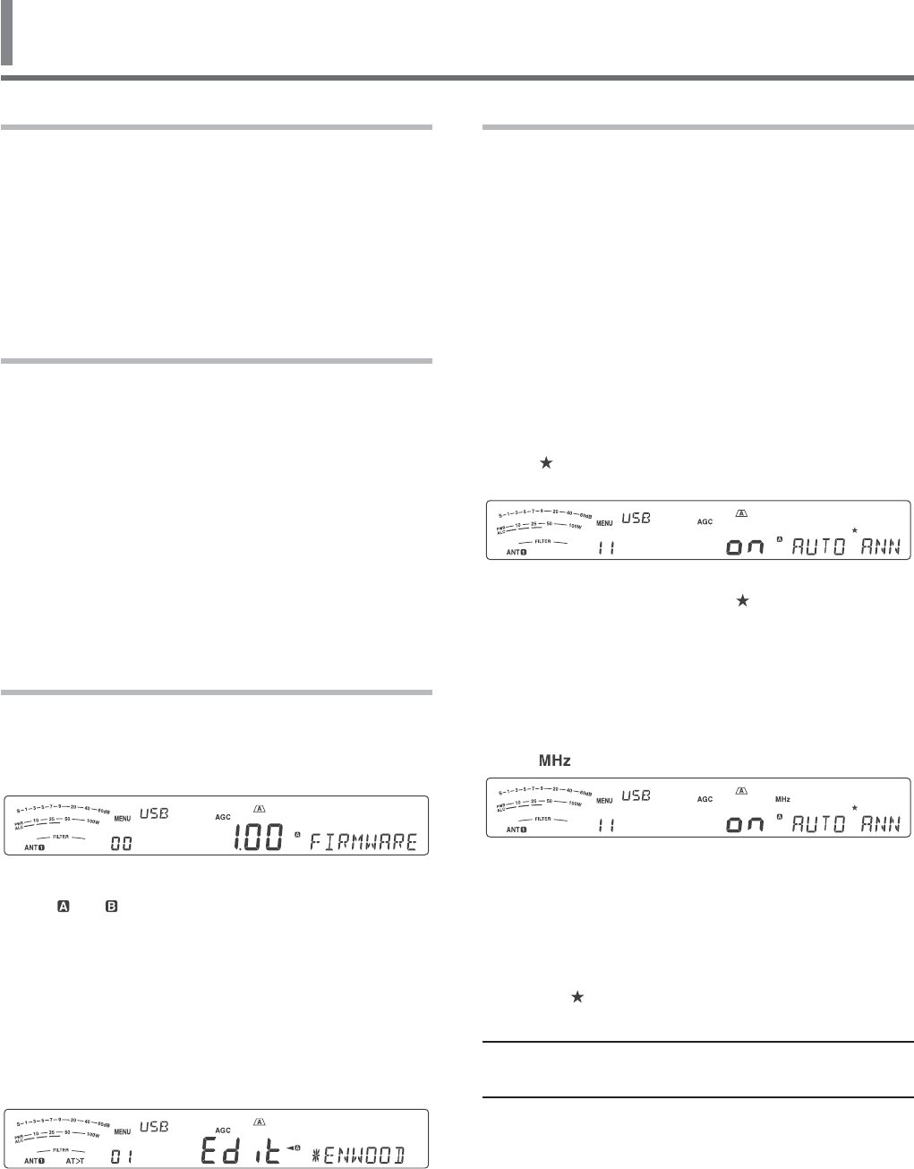
MENU ACCESS
1 Press [MENU].
s 4HE-ENU.OANDSETTINGAPPEARONTHE
display, and the explanation of the menu
appears on the sub-display.
2 Press [A/B (A=B)] to select Menu A or B.
s h vORh ” appears, indicating which Menu is
selected.
3 Press [Q-M.IN]/ [Q-MR] or turn the MULTI/CH
CONTROLTOSELECTTHEDESIRED-ENU.O
s %ACHTIMEYOUCHANGETHE-ENU.O
a different scrolling message appears on the
SUBDISPLAYDESCRIBINGTHE-ENU.O
4 Press [M.IN]/ [SCAN (SG.SEL)], or Mic [UP]/
[DWN] to select a parameter.
5 Press [MENU] to exit Menu mode.
QUICK MENU
Because the number of functions this transceiver
provides is extraordinary, there are numerous items
in each Menu. If you find accessing desired Menu
.OSTOBETOOTIMECONSUMINGUSETHE1UICK-ENUTO
create your own customized, abbreviated Menu. You
CANTHENADDTHOSE-ENU.OSWHICHYOUFREQUENTLY
USETOTHE1UICK-ENU#OPYING-ENU.OSTOTHE
1UICK-ENUHASNOEFFECTONTHE-ENU
PROGRAMMING THE QUICK MENU
1 Press [MENU].
2 Press [Q-M.IN]/ [Q-MR] or turn the MULTI/CH
CONTROLTOSELECTTHEDESIRED-ENU.O
3 Press [FINE (F.LOCK)].
s h ” appears, indicating that the Menu item has
BEENADDEDTOTHE1UICK-ENU
s 4OREMOVETHEITEMFROMTHE1UICK-ENUPRESS
[FINE (F.LOCK)] AGAINh ” disappears.
4 Press [MENU] to exit Menu mode.
USING THE QUICK MENU
1 Press [MENU].
2 Press [MHz].
s h ” appears.
3 Press [Q-M.IN]/ [Q-MR] or turn the MULTI/CH
CONTROLTOSELECTTHEDESIRED1UICK-ENU.O
4 Press [M.IN]/ [SCAN (SG.SEL)], or Mic [UP]/
[DWN] to change the current setting for the
SELECTED-ENU.O
s 7HENTHE-ENUISREGISTEREDTOTHE1UICK-ENU
LISTh ” appears.
5 Press [MENU] TOEXIT1UICK-ENUMODE
Note: )FTHE1UICK-ENUHASNOTBEENPROGRAMMED0RESS
[Q-M.IN]/[Q-MR] or turning the MULTI/CH control in step 2
CAUSESh#(%#+vTOBEOUTPUTIN-ORSECODE

15
MENU SETUP 4
MENU CONFIGURATION
Category No. Description Settings** Ref.
Page
Display* Default**
Operator
Interface
00 Firmware version –79
FIRMWARE6%23)/.
01 Power on message (%,,/%$)4 24
POWER ON-%33!'% +%.7//$
02
Display brightness
Off, 1: minimum, 6: maximum
OFF/ 1 ~ 6 55
$)30,!9BRIGHTNE33 4
03
Display backlight color
1: amber, 2 ~ 9: mixed colors, 10: green 1 ~ 10 55
"!#+,)'(4COLOR 1
04
Panel key response for double function
1: 0.2 second, 2: 0.5 second, 3: 1 second 1/ 2/ 3
55
0!.%,KEY RESP/.3%&/2$/5",%
&5.#4)/.3 2
Volume
05
Beep output level
OFF, 1: minimum, 9: maximum
OFF/ 1 ~ 20 (1 step) 54
BEEP VOL5-% 10
06
3IDETONEVOLUME
OFF, 1: minimum, 9: maximum
OFF/ 1 ~ 20 (1 step) 24, 37
SIDETONE6/,5-% 10
07
6'3MESSAGEPLAYBACKVOLUME
OFF, 1: minimum, 9: maximum
OFF/ 1 ~ 20 (1 step) 63
-%33!'%PLAYBACK6/,5-% 10
6OICE'UIDE
08
6'3ANNOUNCEMENTVOLUME
OFF, 1: minimum, 7: maximum
OFF/ 1~ 20 (1 step) 66
6/)#%GUIDE VO,5-% 10
09
6'3ANNOUNCEMENTSPEED
0: slow, 4: fast 0 ~ 4 (1 step) 66
6/)#%GUIDE SP%%$ 1
10
6'3ANNOUNCEMENTLANGUAGE
%.%NGLISH*0*APANESE %.*0 66
6/)#%GUIDE LA.'5!'% %.
11 6'3AUTOANNOUNCEMENT OFF/ 1/ 2 63
AUTO ANN/5.#%-%.4 1
Tuning
12 -(ZSTEP ;-(Z= 30
MHZ STEP 1
13
Tuning control adjustment rate ;(Z=
31
45.).'#/.42/,CHANGE R!4%0%2
2%6/,54)/. 1000
14
2OUNDSOFF6&/FREQUENCIESCHANGEDBYUSINGTHE
MULTI/CH control /&&/.
30
&2%15%.#9ROUNDING/&&7(%.53).'
-5,4)#(#/.42/, /.

16
4 MENU SETUP
Category No. Description Settings** Ref.
Page
Display* Default**
Tuning
(continued)
15
K(ZFREQUENCYSTEPSIZEFORTHEMULTI/CH
control in AM mode on the AM broadcast band /&&/.
30
-5,4)#(#/.42/,9KHZ STE0#(!.'%).
!-"2/!$#!34"!.$
+TYPE/&&
%TYPE/.
16
Frequency step size for the MULTI/CH control in
33"MODE
OFF/ 0.5/ 1/ 2.5/ 5/ 10
;K(Z= 30
MULTI/CH#/.42/, 5
17
Frequency step size for the MULTI/CH control in
#7&3+MODE
OFF/ 0.5/ 1/ 2.5/ 5/ 10
;K(Z= 30
CW MULTI/CH CONTROL 0.5
18
Frequency step size for the MULTI/CH control in
AM mode
5/ 6.25/ 10/ 12.5/ 15/ 20/
;K(Z= 30
AM MULTI/#(#/.42/, 5
19
Frequency step size for the MULTI/CH control in
FM mode
5/ 6.25/ 10/ 12.5/ 15/ 20/
;K(Z= 30
FM MULTI/#(#/.42/, 10
20
3HIFTABLE28FREQUENCYDURINGSPLITTRANSMISSION /&&/.
25
SHIFTABLE28&2%15%.#9$52).'30,)4
42!.3-)33)/. OFF
-EMORY#HANNEL
21 .UMBEROFQUICKMEMORYCHANNELS ;CH= 47
.5-"%2/&QUICK ME-/29#(!..%,3 5
22 Tunable memory recall frequencies /&&/. 44
TUNABLE-%-/292%#!,,&2%15%.#)%3 OFF
3CAN
23 Program scan partially slowed /&&/. 49
02/'2!-3#!.0!24)!,,9SLOWED /.
24 3LOWDOWNFREQUENCYRANGEFORTHEPROGRAMSCAN 100/ 200/ 300/ 400/ 500
;(Z= 49
02/'2!-3,/7SCAN RAN'% 300
25 Program scan hold /&&/. 50
02/'2!-SCAN HOLDOFF
26 3CANRESUMEMETHOD 4/#/ 50
SCAN RES5-%-%4(/$ TO
Auto Mode 27 Auto mode operation /./&& 53
AUTO MOD%/0%2!4)/. OFF
$30&UNCTION
28 33"lLTERTYPESELECTION 1/ 2 40
SSB FILT%2490%3%,%#4)/. ª(),/
29 33"$!4!lLTERTYPESELECTION 1/ 2 40
33"DATA FIL4%2490%3%,%#4)/. 7)$4(3()&4
30 Auto notch tracking speed 0 ~ 4 (1 step) 41
!54/NOTCH TR!#+).'30%%$ 2
31 48lLTERFOR33"!-LOWCUT 10/ 100/ 200/ 300/ 400/
;(Z= 34
48&),4%2&/2SSB/AM L/7#54 300
32 48lLTERFOR33"!-HIGHCUT 2500/ 2600/ 2700/ 2800/
;(Z= 34
48&),4%2&/2SSB/AM H)'(#54 2700

17
MENU SETUP 4
Category No. Description Settings** Ref.
Page
Display* Default**
$30&UNCTION
(continued)
33 48lLTERFOR33"$!4!LOWCUT 10/ 100/ 200/ 300/ 400/
;(Z= 34
48&),4%2&/233"DATA LOW#54 300
34 48lLTERFOR33"$!4!HIGHCUT 2500/ 2600/ 2700/ 2800/
;(Z= 34
48&),4%2&/233"DATA HIG(#54 2700
35 3PEECHPROCESSOREFFECT 3/&4(!2$ 33
30%%#(02/#%33/2EFFECT (!2$
%QUALIZER
36
$3048EQUALIZER
O&&/FF(B(IGHBOOST(B(IGHBOOST&0
Formant pass, bb1: Bass boost1,
BB"ASSBOOSTC#ONVENTIONAL
55SER2ESERVEDFOR!2#0SOFTWARE
/&&("("&0""
""#5 34
$30TX EQUAL):%2 OFF
37
$3028EQUALIZER
O&&/FF(B(IGHBOOST(B(IGHBOOST&0
Formant pass, bb1 Bass boost1,
BB"ASSBOOST&,!4&LAT
55SER2ESERVEDFOR!2#0SOFTWARE
/&&("("&0""
""&,!45 57
$30RX EQUAL):%2 OFF
#7
38 %LECTRONICKEYERMODE A/ B 35
%,%#42/.)#KEYER MO$% B
39 +EYINGPRIORITYOVERPLAYBACK /&&/. 36
KEYING P2)/2)49/6%20,!9"!#+ OFF
40 #728PITCH48SIDETONEFREQUENCY ^;(Z=STEP 24
CW RX PI4#(483)$%4/.%&2%15%.#9 800
41 #7RISETIME ;MS= 36
CW RISE4)-% 6
42 #7KEYINGDOTDASHWEIGHTRATIO !54/^
(0.1 step) 36
CW WEIGH4).' !54/
43 2EVERSE#7KEYINGAUTOWEIGHTRATIO /&&/. 36
REVERSED#77%)'(4).' OFF
44 Bug key function /&&/. 36
BUG KEY&5.#4)/. OFF
45 2EVERSEDDOTANDDASHKEYING /&&/. 38
2%6%23%$DOT AND$!3(+%9).' OFF
46
-)#50$7.KEYPADDLEFUNCTION
PF: PF key PA: Paddle PF/ PA 38
-)#UP/DWN K%9&5.#4)/. PF
47 !UTO#748WHENKEYINGIN33" /&&/. 38
AUTO CW487(%.+%9).').33" OFF
48
&REQUENCYCORRECTIONFORCHANGING33"TO#7 /&&/.
38
&2%15%.#9#/22%#4)/.&/2SSB-TO-C7
#(!.'% OFF

18
4 MENU SETUP
Category No. Description Settings** Ref.
Page
Display* Default**
#7CONTINUED 49
.O"REAKINOPERATIONWHILEADJUSTINGKEYING
speed /&&/.
35
NO BREAK-IN/0%2!4)/.7(),%!$*534).'
+%9).'30%%$ OFF
&3+
50 &3+SHIFT ;(Z= 39
FSK SHIFT170
51 &3+KEYINGPOLARITY /&&/. 39
2%6%23%$FSK KEY$/7.0/,!2)49 OFF
52 &3+TONEFREQUENCY ;(Z= 39
FSK TONE&2%15%.#9 2125
FM 53
-)#GAINFOR&-
,OW-ID(I 1 ~ 3 22
FM MIC G!). 1
48#ONTROL
54 Fine transmission power tuning /&&/. 58
FINE TRA.3-)40/7%2#(!.'%34%03 OFF
55 Time-out timer OFF/ 3/ 5/ 10/ 20/ 30
(min) 58
TIME-OUT4)-%2 OFF
Transverter 56 Xverter/ power down of Xverter OFF/ 1/ 2 58
86%24%20/7%2$/7./&XVERTER OFF
Antenna Tuner
57 TX hold when AT completes the tuning /&&/. 52
!.4%..!45.%2TX HOLD OFF
58 In-line AT while receiving /&&/. 52
!.4%..!TUNER FO22%#%04)/. OFF
,INEAR!MP
59 ,INEARAMPLIlERCONTROLRELAYFOR(&BAND OFF/ 1/ 2/ 3/ 4/ 5 55
HF LINEA2!-0,)&)%2#/.42/,2%,!9 OFF
60 ,INEARAMPLIlERCONTROLRELAYFOR-(ZBAND OFF/ 1/ 2/ 3/ 4/ 5 55
50MHZ LI.%!2!-0,)&)%2#/.42/,2%,!9 OFF
Message
61 #ONSTANTRECORDING /&&/. 63
CONSTANT2%#/2$).' /.
62 2EPEATTHEPLAYBACK /&&/. 36, 62
0,!9"!#+REPEAT OFF
63 Interval time for repeating the playback ^;S=STEP 36, 62
0,!9"!#+INTERVAL4)-% 10
3PLIT4RANSFER
64
3PLITFREQUENCYTRANSFERINMASTERSLAVEOPERATION /&&/.
60
TRANSFER30,)4&2%15%.#9$!4!4/
!./4(%242!.3#%)6%2 OFF
65
0ERMITTOWRITETHETRANSFERRED3PLITFREQUENCIESTO
the target VFOs/&&/. 60
COPY SPL)4&2%15%.#9$!4!4/6&/ OFF
TX Inhibit 66 TX inhibit /&&/. 34
TX INHIBIT OFF

19
MENU SETUP 4
Category No. Description Settings** Ref.
Page
Display* Default**
0#
#OMMUNICATION
67 #/-PORTCOMMUNICATIONSPEED 4800/ 9600/ 19200/
38400/ 57600/ 115200 60
COM PORT"!5$2!4% 9600 (bps)
68 53"PORTCOMMUNICATIONSPEED 4800/ 9600/ 19200/
38400/ 57600/ 115200 60
USB PORT"!5$2!4% 115200 (bps)
%XTERNAL!UDIO
(Input/ Output)
69
Audio input line selection for data communications !##53"
61
!5$)/).054LINE SEL%#4)/.&/2$!4!
#/--5.)#!4)/.3 !##
70 3OURCEFOR0443%.$TRANSMISSION &2/.42%!2 61
SOURCE/&0443%.$42!.3-)33)/. &2/.4
71
!UDIOLEVELOF53"INPUTFORDATACOMMUNICATIONS 0 ~ 9 (1 step)
61
!5$)/,%6%,/&USB INPU4&/2$!4!
#/--5.)#!4)/.3 4
72
!UDIOLEVELOF53"OUTPUTFORDATACOMMUNICATIONS 0 ~ 9 (1 step)
61
!5$)/,%6%,/&USB OUTP54&/2$!4!
#/--5.)#!4)/.3 4
73
!UDIOLEVELOF!##INPUTFORDATACOMMUNICATIONS 0 ~ 9 (1 step)
61
!5$)/,%6%,/&ACC2 INP54&/2$!4!
#/--5.)#!4)/.3 4
74
!5$)/LEVELOF!##OUTPUTFORDATA
communications 0 ~ 9 (1 step)
61
!5$)/,%6%,/&ACC2 OUT054&/2$!4!
#/--5.)#!4)/.3 4
75
-IXINGBEEPTONESFOR!##53"AUDIOOUTPUT /&&/.
61
MIXING B%%04/.%3&/2!##53"!5$)/
/54054 OFF
%XTERNAL
Accessory
#ONTROL
76 Data VOX /&&/. 32
6/8/0%2!4)/.WITH DAT!).054 OFF
77 Data VOX delay time 0 ~ 100 (5 step) 33
DATA VOX DELA94)-% 50
78 $ATA6/8GAINFORTHE53"AUDIOINPUT 0 ~ 9 (1 step) 33
USB VOX'!). 4
79 $ATA6/8GAINFORTHE!##TERMINAL 0 ~ 9 (1 step) 33
ACC2 VOX'!). 4
80 0+3POLARITY /&&/. 66
2%6%23%$PKS POLA2)49 OFF
81 Busy lockout (TX)/&&/. 34
"539&2%15%.#942!.3-)33)/.LOCKOUT OFF
82 #4#33MUTECONTROL 1/ 2 61
#4#33MUTE CON42/, 1
83 031CONTROLSIGNALLOGIC ,//0%. 61
PSQ OUTP54,/')# ,/
84 031SOURCEOUTPUTCONDITION /&&"3931,3.$
"393.$31,3.$ 61
PSQ SOUR#% 31,
85 $26CONNECTOROUTPUTFUNCTIONMODE $2/!.4 52
DRV CONN%#4/2&5.#4)/. $2/

20
4 MENU SETUP
Category No. Description Settings** Ref.
Page
Display* Default**
Timer 86 APO (Auto Power Off) function /&&;MIN= 52
AUTO POW%2/&& OFF
0&+EYS
87 Front panel PF A key assignment 0 ~ 99, 120 ~ 170,
200 ~ 209, OFF 56
&2/.40!.%,PF A KEY!33)'.-%.4 ;6/)#%=
88 Front panel PF B key assignment 0 ~ 99, 120 ~ 170,
200 ~ 209, OFF 56
&2/.40!.%,PF B KEY!33)'.-%.4 ;6/)#%=
89 &RONTPANEL2)4KEYASSIGNMENT 0 ~ 99, 120 ~ 170,
200 ~ 209, OFF 56
RIT KEY !33)'.-%.4 165
90 Front panel XIT key assignment 0 ~ 99, 120 ~ 170,
200 ~ 209, OFF 56
XIT KEY!33)'.-%.4 166
91 &RONTPANEL#,KEYASSIGNMENT 0 ~ 99, 120 ~ 170,
200 ~ 209, OFF 56
CL KEY A33)'.-%.4 167
92 &RONTPANEL-5,4)#(KEYASSIGNMENT 0 ~ 99, 120 ~ 170,
200 ~ 209, OFF 56
MULTI CH+%9!33)'.-%.4 131
93 &RONTPANEL-5,4)#(KEYASSIGNMENT#7 0 ~ 99, 120 ~ 170,
200 ~ 209, OFF 56
CW MULTI#(+%9!33)'.-%.4 133
94 Microphone PF 1 key assignment 0 ~ 99, 120 ~ 170,
200 ~ 209, OFF 56
-)#PF 1 KEY!33)'.-%.4 151;!"=
95 Microphone PF 2 key assignment 0 ~ 99, 120 ~ 170,
200 ~ 209, OFF 56
-)#PF 2 KEY!33)'.-%.4 148;30,)4=
96 Microphone PF 3 key assignment 0 ~ 99, 120 ~ 170,
200 ~ 209, OFF 56
-)# PF 3 KEY!33)'.-%.4 154;-6=
97 Microphone PF 4 key assignment 0 ~ 99, 120 ~ 170,
200 ~ 209, OFF 56
-)#PF 4 KEY!33)'.-%.4 ;-/.)4/2=
98 -ICROPHONE$7.KEYASSIGNMENT 0 ~ 99, 120 ~ 170,
200 ~ 209, OFF 56
MIC DOWN+%9!33)'.-%.4 ;$/7.=
99 -ICROPHONE50KEYASSIGNMENT 0 ~ 99, 120 ~ 170,
200 ~ 209, OFF 56
MIC UP K%9!33)'.-%.4 208;50=
4HEBOLDEDLETTERINGOFTHEDISPLAYMESSAGEISWHATAPPEARSONTHEDISPLAYWHILEPAUSED
3ETTINGSANDDEFAULTVALUESMAYBEMODIlED
!FTERCHANGINGTHISSETTINGVIATHEMENUTURNTHEPOWER/&&ANDTHENBACK/.TOIMPLEMENTTHECHANGE
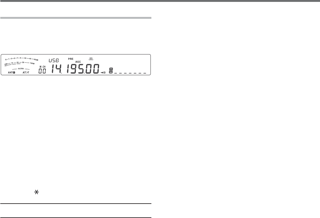
21
MENU SETUP 4
CHARACTER ENTRY
7HENCHARACTERENTRYISREQUIREDACURSORWILLAPPEAR
on the display.
1 Move the cursor to the left or right by pressing
[Q-M.IN] or [Q-MR].
2 Turn the MULTI/CH control or press [M.IN]/ [SCAN
(SG.SEL)] to select your desired character.
s 9OUCANDELETETHESELECTEDCHARACTERBY
pressing [CL].
3 2EPEATSTEPSANDTOENTERTHEREMAINING
characters.
4 Press [MENU] to set the entry and to exit character
entry mode.
s 0RESS[CLR] at any time to cancel character
entry mode and return to the Menu selection.
Available alphanumeric characters:
!"#$%&'()*+,-./01Q2345678
Y Z
(space) + – / 0 1 2 3 4 5 6 7 8 9
Note: 2EFERTOPAGETOCHANGETHE0OWER/NMESSAGEAND
PAGETOREGISTERA-EMORY#HANNELNAME
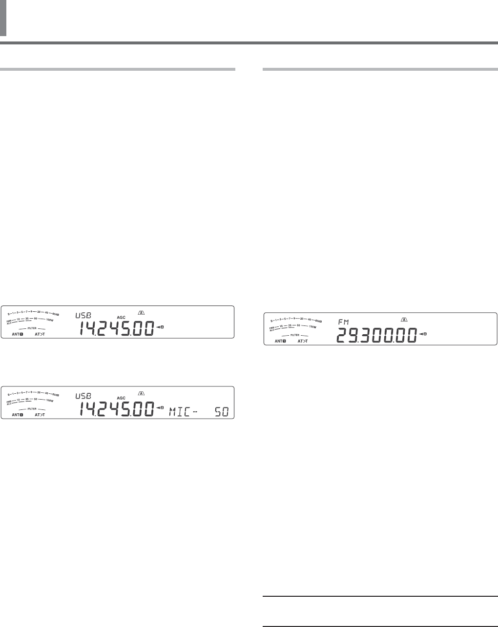
22
5 BASIC COMMUNICATIONS
SSB TRANSMISSION
SSB is the most commonly-used mode on the HF
Amateur radio bands. Compared with other voice
modes, SSB requires only a narrow bandwidth for
communications. SSB also allows long distance
communications with minimum transmission power.
If necessary, refer to “OPERATING BASICS”,
beginning on page 10, for details on how to receive.
1 Select an operating frequency.
2 Press [LSB/USB] until “USB” or “LSB” appears on
the operating mode display.
s )FTHEDESIREDSIDEBANDh53"vORh,3"vDOES
not appear, select the other sideband first.
Then, press [LSB/USB]. The mode indicator
changes to your desired sideband.
s h53"vREPRESENTSTHEUPPERSIDEBANDAND
“LSB” represents the lower sideband. Normally,
USB is used for the communications for
10 MHz and above while LSB is used for the
frequencies below 10 MHz.
3 Press [MIC (CAR)] to adjust the Microphone gain.
s 4HECURRENTGAINLEVELAPPEARSONTHESUB
display.
4 Press and hold Mic [PTT].
s 4HE4828,%$LIGHTSRED
s 2EFERTOh6/8v[PAGE32} for information on
AUTOMATIC4828SWITCHING
5 Speak into the microphone and turn the
MULTI/CH control so that the ALC meter reflects
your voice level but does not exceed the ALC limit.
s 3PEAKINYOURNORMALTONEANDLEVELOFVOICE
Speaking too close to the microphone or too
loudly may increase distortion and reduce
intelligibility at the receiving end.
s 9OUMAYWANTTOUSETHE3PEECH0ROCESSOR
2EFERTOh30%%#(02/#%33/2v[PAGE33} for
details.
6 Release Mic [PTT] to return to Reception mode.
s 4HE4828,%$LIGHTSGREENORTURNSOFF
depending on the SQL control position.
7 Press [MIC (CAR)] or [CLR] to exit the Microphone
gain adjustment.
2EFERTOh#/--5.)#!4).'!)$3vBEGINNINGON
page 30, for information on additional useful operation
functions.
FM TRANSMISSION
&-ISACOMMONMODEFORCOMMUNICATINGON6(&OR
UHF frequencies. As for HF and the 6 m band,
29 MHz and 51-54 MHz bands are commonly used
FOR&-OPERATION9OUCANALSOUTILIZEMMBAND
repeaters to reach your friends when they are outside
or skipped over from your coverage. Although FM
requires a wider bandwidth when compared to SSB
or AM mode, it has the finest audio quality among
these modes. When combined with the full-quieting
aspect of FM signals, which suppresses background
noise on the frequency, FM can be the best method
for maintaining casual communications with your local
friends.
If necessary, refer to “OPERATING BASICS”,
beginning on page 10, for details on how to receive.
1 Select an operating frequency.
2 Press [FM/AM (FM-N)] until “FM” appears.
s )Fh&-vDOESNOTAPPEARSELECTh!-vTHENPRESS
[FM/AM (FM-N)]. The mode indicator changes
to “FM”.
3 Press and hold Mic [PTT].
s 4HE4828,%$LIGHTSRED
s 2EFERTOh6/8v[PAGE32} for information on
AUTOMATIC4828SWITCHING
4 Speak into the microphone in your normal voice.
s 3PEAKINGTOOCLOSETOTHEMICROPHONEORTOO
loudly may increase distortion and reduce
intelligibility at the receiving end.
s 9OUCANSWITCHTHE-ICROPHONEGAINFOR&-
BETWEEN.ORMAL-EDIUMAND(IGH
by using Menu No. 53.ORMALISUSUALLY
APPROPRIATEHOWEVERSELECT(IGHIFOTHER
stations report that your modulation is weak.
5 Release Mic [PTT] to return to Reception mode.
s 4HE4828,%$LIGHTSGREENORTURNSOFF
depending on the SQL control position.
2EFERTOh#/--5.)#!4).'!)$3vBEGINNINGON
page 30, for additional information on useful operation
functions.
Note: Microphone gain adjustment for SSB or AM has no
EFFECTIN&-MODE)N&-MODEYOUMUSTSELECT.ORMAL
-EDIUMOR(IGHIN-ENU.O53.
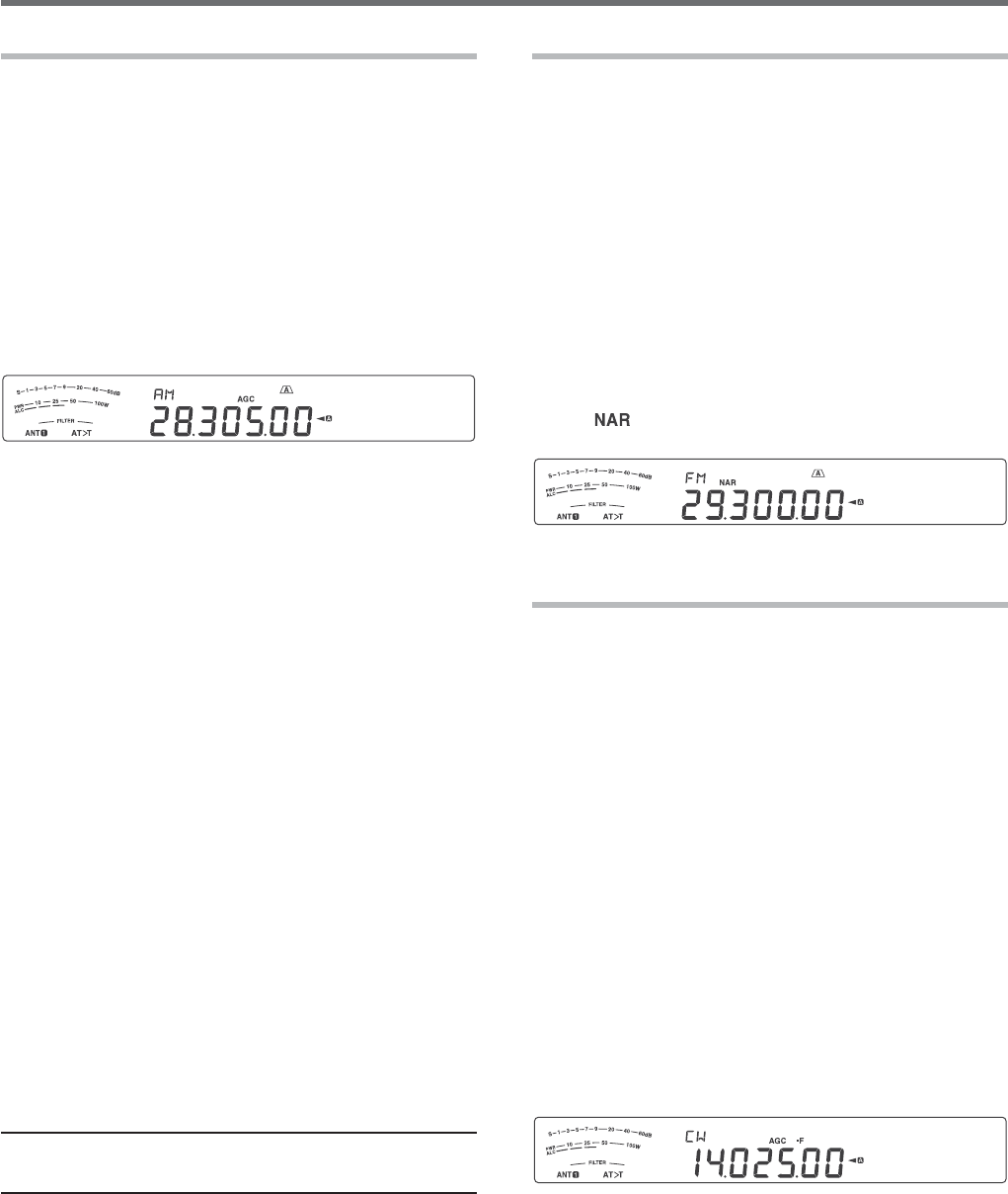
23
BASIC COMMUNICATIONS 5
AM TRANSMISSION
Each mode used on the HF Amateur bands has its
OWNADVANTAGES!LTHOUGHLONGDISTANCE$8CONTACTS
may be less common while using AM, the superior
audio quality characteristic of AM operation is one
reason why some hams prefer this mode.
If necessary, refer to “OPERATING BASICS”,
beginning on page 10, for details on how to receive.
1 Select an operating frequency.
2 Press [FM/AM (FM-N)] until “AM” appears.
s )Fh!-vDOESNOTAPPEARSELECTh&-vlRSTTHEN
press [FM/AM (FM-N)]. The mode indicator
changes to “AM”.
3 Press [MIC (CAR)] to enter the Microphone gain
adjustment mode.
s 4HECURRENTGAINLEVELAPPEARSONTHESUB
display.
4 Press and hold Mic [PTT].
s 4HE4828,%$LIGHTSRED
s 2EFERTOh6/8v[PAGE]FORINFORMATIONON
AUTOMATIC4828SWITCHING
5 Speak into the microphone and adjust the
MULTI/CH control so that the power meter slightly
reflects your voice level.
s 3PEAKINYOURNORMALTONEANDLEVELOFVOICE
Speaking too close to the microphone or too
loudly may increase distortion and reduce
intelligibility at the receiving end.
s 9OUMAYWANTTOUSETHE3PEECH0ROCESSOR
2EFERTOh30%%#(02/#%33/2v[PAGE33} for
details.
6 Release Mic [PTT] to return to Reception mode.
s 4HE4828,%$LIGHTSGREENORTURNSOFF
depending on the SQL control position.
7 Press [MIC (CAR)] or [CLR] to exit the Microphone
gain adjustment mode.
2EFERTOh#/--5.)#!4).'!)$3vBEGINNINGON
page 30, for information on additional useful operation
functions.
Note: 7HENTHE48POWERMETERREADINGEXCEEDSTHEVALUETHAT
YOUSPECIlEDINTHE480OWERSETTING[PAGE]DECREASETHE
microphone gain or adjust your tone and level of voice.
NARROW BANDWIDTH FOR FM
3ELECTWIDEBANDORNARROWBAND48DEVIATION
depending on whether the other station is using wide
band or narrow band filter for FM mode. While “NAR”
appears, the TS-590S transceiver transmits signals in
narrow band FM but the reception IF filter bandwidth
REMAINSUNCHANGED7IDE4HEDEVIATIONSELECTION
is crucial to avoid audio distortion or insufficient
intelligibility that the other station will encounter.
1 Press [FM/AM (FM-N)] until “FM” appears.
s
If “FM” does not appear, select “AM” first, then
press [FM/AM (FM-N)].
The mode indicator
changes to “FM”.
2 Press and hold [FM/AM (FM-N)] to toggle the
SELECTIONBETWEENWIDEANDNARROW48DEVIATION
s h vAPPEARSWHENNARROW48DEVIATIONIS
selected.
CW TRANSMISSION
CW operators know that this mode is very reliable
when communicating under worst conditions. It may
be true that newer digital modes rival CW as being
equally as useful in poor conditions. These modes,
however, do not have the long history of service nor
the simplicity that CW provides.
This transceiver has a built-in electronic keyer that
supports a variety of functions. For details on using
THESEFUNCTIONSREFERTOh%,%#42/.)#+%9%2v
[PAGE35}.
If necessary, refer to “OPERATING BASICS”,
beginning on page 10, for details on how to receive.
1 Select the operating frequency.
2 Press [CW/FSK (REV)] until “CW” appears.
s )Fh#7vDOESNOTAPPEARSELECTh&3+vlRSTTHEN
press [CW/FSK (REV)]. The mode indicator
changes to “CW”.
s 4OPRECISELYTUNEINANOTHERSTATIONUSE!UTO
Zero-beat. Refer to “AUTO ZERO-BEAT”
[PAGE24}.
3 Press [SEND].
s 4HE4828,%$LIGHTSRED
4 Operate the Keys or Paddle.
s !SYOUTRANSMITYOUSHOULDHEARASIDETONE
that lets you monitor your own transmission.
5 Press [SEND] to return to Reception mode.
s 4HE4828,%$LIGHTSGREENORTURNSOFF
depending on the SQL control setting.
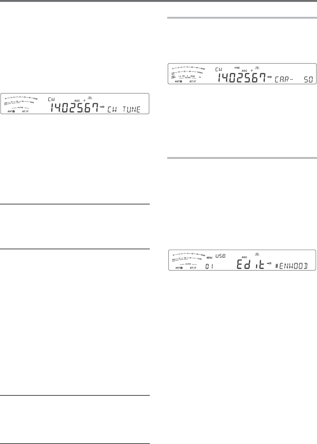
24
5 BASIC COMMUNICATIONS
AUTO ZERO-BEAT
Use Auto Zero-beat before transmitting to tune in a
CW station. Auto Zero-beat automatically and exactly
matches your transmit frequency with the station you
are receiving. Neglecting to do this will reduce your
chances of being heard by the other station.
1 Tune to the CW signal using the Tuning control.
2 Press [CW T. (AGC OFF)] to start Auto Zero-beat
while CW is selected for the operating mode.
s h#745.%vAPPEARS
s 9OURRECEPTIONFREQUENCYAUTOMATICALLYCHANGES
SOTHATTHEPITCHTONEOFTHERECEIVEDSIGNAL
EXACTLYMATCHESTHE48SIDETONE28PITCH
FREQUENCYTHATYOUHAVESELECTED2EFERTOh48
3)$%4/.%280)4#(&2%15%.#9v[BELOW]
s 7HENMATCHINGISCOMPLETEDh#745.%v
disappears.
s )FMATCHINGISUNSUCCESSFULTHEPREVIOUS
frequency is restored.
3 To quit Auto Zero-beat, press [CW T. (AGC OFF)]
or [CLR].
Note:
◆ When using Auto Zero-beat, the matching error is normally
within ±5 Hz.
◆ Auto Zero-beat may fail if the keying speed of the target
station is too slow or if some interference is present.
◆ When the RIT function is ON, only RIT frequencies change
to make the Auto Zero-beat adjustment.
TX SIDETONE/ RX PITCH FREQUENCY
As you send CW, you will hear tones from
THETRANSCEIVERSPEAKER4HESEARECALLED48
TRANSMISSIONSIDETONES,ISTENINGTOTHESETONES
YOUCANMONITORWHATYOUARETRANSMITTING9OUMAY
also use the tones to ensure that your key contacts
are closing, the keyer is functioning, or to practice
sending without actually putting a signal on the air.
28RECEPTIONPITCHREFERSTOTHEFREQUENCYOF#7THAT
you hear after tuning in a CW station.
On this transceiver, the frequency of the sidetone and
28PITCHAREEQUALANDSELECTABLE!CCESS-ENU.O
40 to select the frequency that is most comfortable for
you. The selectable range is from 300 Hz to 1000 Hz
INSTEPSOF(ZDEFAULTIS(Z
4OCHANGETHEVOLUMEOFTHE48SIDETONEACCESS
Menu No. 06. The selections range from 1 to 20 and
/&&DEFAULTIS10
Note:
◆ The position of the AF control does not affect the volume of
THE48SIDETONE
◆ 7HENCHANGINGTHE#7PITCHSIDETONETHESHIFTAMOUNT
OFTHERECEIVElLTERISAUTOMATICALLYAPPLIEDTOTHE#7PITCH
SIDETONE)N1UICK-EMORYMODETHE#7PITCHSIDETONE
is not revised since the receive filter information stored in the
1UICK-EMORYHASPRIORITY
CARRIER LEVEL
When using AM, CW, or FSK mode, you can adjust
the carrier level.
1 Press and hold [MIC (CAR].
s 4HECURRENTGAINLEVELAPPEARSONTHESUB
display.
2 Turn the MULTI/CH control so that the ALC meter
reads within the limits of the ALC zone.
s &OR!-MODEADJUSTTHEMULTI/CH control so
that the ALC meter just begins to indicate.
3 Press and hold [MIC (CAR] again or press [CLR]
to complete the setting.
POWER ON MESSAGE
Each time you switch the transceiver ON,
h+%.7//$vDEFAULTAPPEARSONTHESUBDISPLAY
FORAPPROXIMATELYSECONDS9OUCANPROGRAMYOUR
FAVORITEMESSAGEINPLACEOFTHEDEFAULTMESSAGE9OU
CANENTERAMESSAGEUSINGUPTOCHARACTERS
1 Press [MENU], then press [Q-M.IN][Q-MR] or
turn the MULTI/CH control to access Menu No 01.
2 Press [M.IN][SCAN (SG.SEL)] to begin editing
the message.
3 Move the cursor to the left or right by pressing
[Q-M.IN] or [Q-MR].
4 Press [M.IN][SCAN (SG.SEL)] or turn the MULTI/
CH control to select your desired character.
s 9OUCANDELETETHESELECTEDCHARACTERBY
pressing [CL].
5 Repeat steps 3 and 4 to enter the remaining
characters.
6 Press [MENU] to set the entry and exit character
entry mode.
s 0RESS[CLR] at any time to cancel character
entry mode and exit the Menu mode.
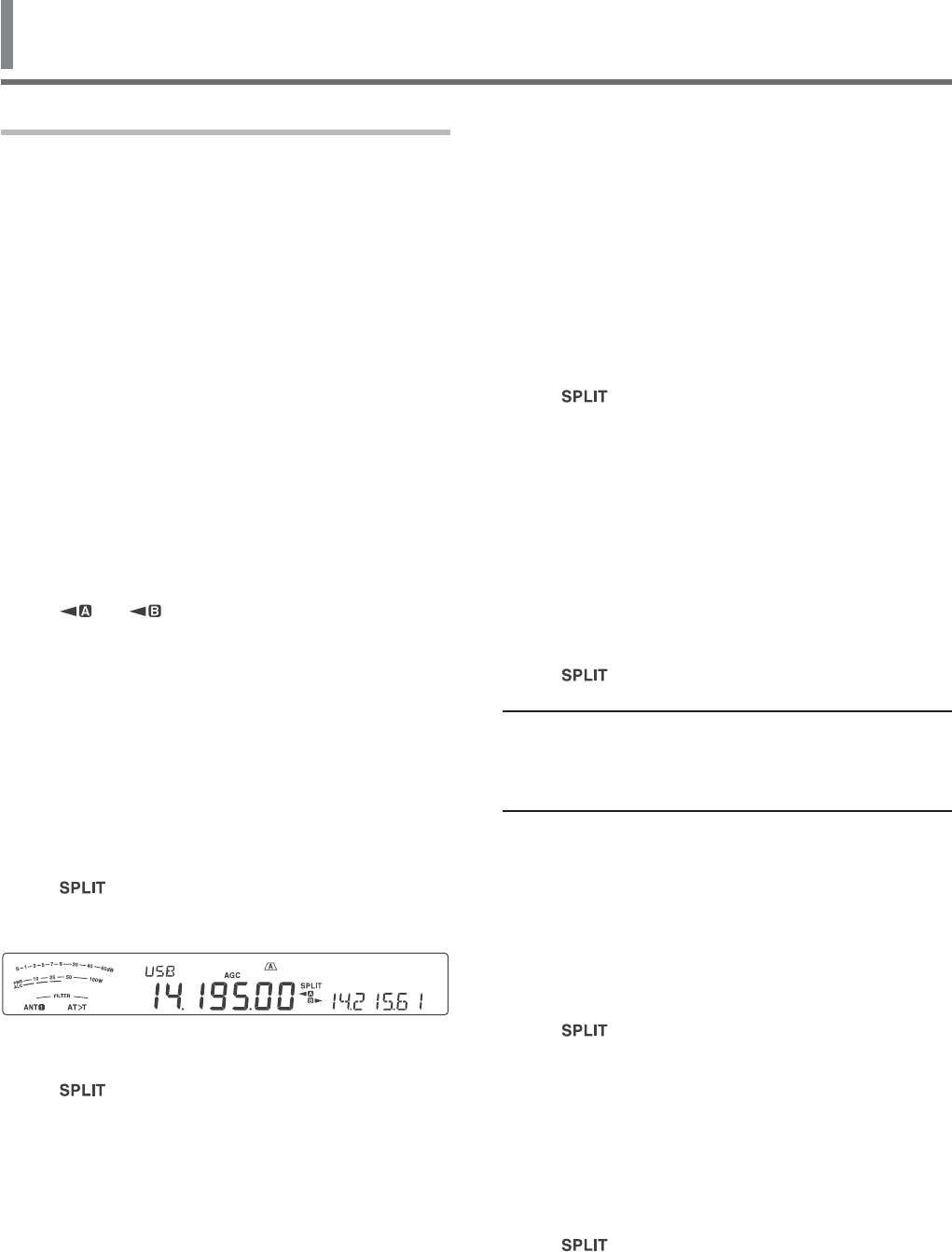
25
6 ENHANCED COMMUNICATIONS
SPLIT-FREQUENCY OPERATION
Usually you can communicate with other stations
using a single frequency for receiving and transmitting.
In this case, you select only one frequency on either
VFO A or VFO B. However, there are cases where
you must select one frequency for receiving and a
different frequency for transmitting. This requires the
use of 2 VFOs. This is referred to as “split-frequency
operation”. One typical case which requires this type
of operation is when you use an FM repeater {page
26}. Another typical case is when you call a rare DX
station.
When a rare or desirable DX station is heard, that
operator may immediately get many simultaneous
responses. Often, such a station is lost under the noise
and confusion of many calling stations. If you find that
you are suddenly being called by many operators, it
is your responsibility to control the situation. You may
announce that you will be “listening up 5 (kHz, from
your present transmission frequency)”, or “listening
down between 5 and 10 (kHz)”.
1 Press [A/B (A=B)] to select VFO A or VFO B.
s h ” or “ ” appears to show which VFO is
selected.
2 Select an operating frequency.
s 4HISFREQUENCYWILLBEUSEDFORTRANSMISSION
s 4OCOPYTHESELECTED6&/FREQUENCYTOTHE
other VFO, press and hold [A/B (A=B)].
3 Press [A/B (A=B)] to select the other VFO.
4 Select an operating frequency.
s 4HISFREQUENCYWILLBEUSEDFORRECEPTION
5 Press [SPLIT].
s h ” appears.
s %ACHTIMEYOUPRESS[A/B (A=B)], the reception
and transmission frequencies are swapped.
6 To quit split-frequency operation, press [SPLIT]
again.
s h ” disappears.
SHIFTABLE RX FREQUENCY DURING SPLIT
TRANSMISSION
When the shiftable function of the RX frequency
in split transmission is set to ON, it is possible to
change the RX frequency by turning the Tuning control
during split transmission. (When it is set to OFF, the
TX frequency changes by turning the Tuning control
during split transmission.)
1 Press [MENU], then press [Q-M.IN]/ [Q-MR] or
turn the MULTI/CH control to select Menu No. 20.
2 Press [M.IN]/ [SCAN (SG.SEL)] to select “on”
3 Press [MENU] to exit Menu mode.
s 7HENYOUSWITCHTHETRANSCEIVER/.WHILETHIS
function is set to ON, the decimal point at the
right end digit of the main display flashes for
approximately 2 seconds after the Power On
message is displayed.
DIRECTLY ENTERING THE FREQUENCY SPLIT
SPECIFIED BY A DXer
To directly enter the difference between the TX
and RX frequencies specified by a DXer, follow the
instruction below while receiving on the main band of
a signal from the DXer.
1 Press and hold [SPLIT].
s h ” blinks.
2 %NTERTHEFREQUENCYDIFFERENCETHEhSPLITvINTHE
order of kHz as specified by the DX station.
If the frequency specified by the DXer is higher
than your current frequency, enter the specified
frequency in the order of kHz using the numeric
and band-select keypad. Conversely, if the
specified frequency is lower, prefix a value of
"0" to the frequency.
s &OREXAMPLEENTERAVALUEOFTOINCREMENT
the frequency by 5 kHz, and enter a value of
"05" to decrement the frequency by 5 kHz.
s h ” switches from split operation to simplex
operation.
Note:
◆ Pressing [SPLIT] switches from split operation to simplex
operation.
◆ To temporarily receive using the transmit frequency, use the
4&3%4FUNCTION
TURN THE TUNING CONTROL TO SEARCH FOR
THE TRANSMIT FREQUENCY
To directly search for the transmit frequency by
rotating the Tuning control, follow the instruction
below while receiving on the main band of a signal
from the DX station.
1 Press and hold [SPLIT].
s h ” blinks.
2 Turn the Tuning control to search for the frequency.
s 4HEFREQUENCYCANBECHANGEDEVENIFTHE
frequency has been locked.
s 0RESS[CLR] to stop searching.
3 Press [SPLIT] to end.
s 4HEFREQUENCYISCONlGUREDASTHETRANSMIT
frequency and split operation begins.
s h ” lights.
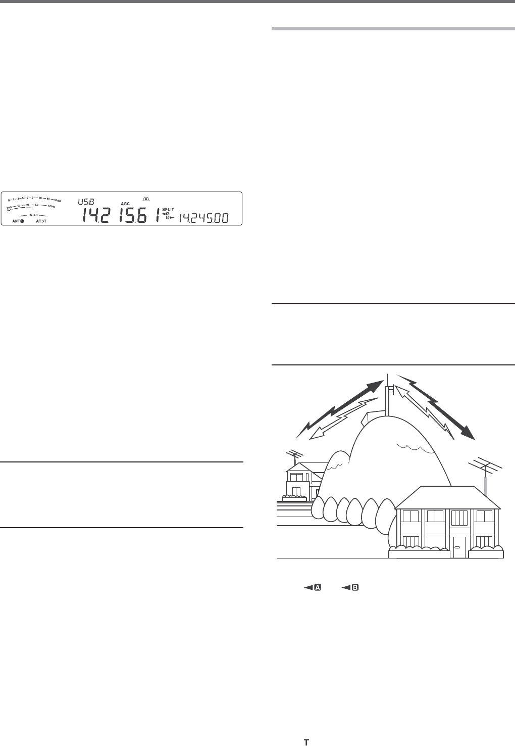
26
6 ENHANCED COMMUNICATIONS
TF-SET (TRANSMISSION FREQUENCY SET)
4&3%4ALLOWSYOUTOTEMPORARILYSWITCHYOUR
transmission frequency and reception frequency.
Canceling this function immediately restores the
original transmission and reception frequencies.
"YACTIVATING4&3%4YOUCANLISTENONYOURTRANSMIT
frequency, and change it while listening. This allows
you to check whether or not the newly selected
transmission frequency is free of interference.
1 Configure split-frequency operation as explained in
the previous section.
2 Press and hold [TF-SET], then turn the Tuning
control or press Mic [UP]/ [DWN] to change the
transmission frequency.
s 4HETRANSCEIVERRECEIVESONTHEFREQUENCYAS
you change, but the frequency shown on the
sub-display (the original reception frequency)
stays unchanged.
3 Release [TF-SET].
s 9OUARENOWRECEIVINGAGAINONYOURORIGINAL
reception frequency.
Successfully contacting a DX station in a pileup
often depends on making a well-timed call on a clear
frequency. That is, it is important to select a relatively
clear transmission frequency and to transmit at the
exact instant when the DX station is listening but the
majority of the groups aren’t transmitting. Switch
your reception and transmission frequencies by using
THE4&3%4FUNCTIONANDLISTENTOYOURTRANSMISSION
frequency. You will soon learn the rhythm of the
DX station and the pileup. The more proficient you
become at using this function, the more DX stations
you will contact.
Note:
◆ 4&3%4ISDISABLEDWHILETRANSMITTING
◆ You can change the transmission frequency even when the
Frequency lock function is ON.
◆ An RIT offset frequency is not added; however, an XIT offset
FREQUENCYISADDEDTOTHETRANSMITFREQUENCYDURING4&3%4
FM REPEATER OPERATION
Most Amateur radio voice repeaters use a separate
reception and transmission frequency. The
transmission frequency may be higher or lower than
the reception frequency. In addition, some repeaters
may require the transceiver to transmit a subtone
before the repeater can be used.
Compared to simplex communication, you can
usually transmit over much greater distances by
using a repeater. Repeaters are typically located
on a mountain top or other elevated location. Often
THEYOPERATEATHIGHER%20%FFECTIVE2ADIATED
Power) than a typical station. This combination of
ELEVATIONANDHIGH%20ALLOWSCOMMUNICATIONSOVER
considerable distances.
HF/ 6 m band repeaters usually operate in the
29 MHz FM sub-band and 51-54 MHz band. This
special service combines the advantages of FM
operation, good fidelity with noise and interference
immunity, with the excitement of HF DX (long
DISTANCECOMMUNICATIONS%VENONAQUIETDAY
10 m FM provides reliable around-town
communications with the potential for sudden DX from
across the country or around the world.
Note:
◆ When programming 2 separate frequencies using 2 VFOs,
be sure to select FM mode on both VFOs.
◆ When operating through a repeater, over deviation caused
by speaking too loudly into the microphone can cause your
signal to “talk-off” (break up) through the repeater.
29.520 MHz
88.5 Hz
29.520 MHz
88.5 Hz
29.620 MHz
29.620 MHz
1 Press [A/B (A=B)] to select VFO A or VFO B.
s h ” or “ ” appears to show which VFO is
selected.
2 Turn the Tuning control or the MULTI/CH control to
select the reception frequency.
3 Press [FM/AM (FM-N)] to select FM mode.
4 Press and hold [A/B (A=B)] to duplicate the
frequencies and other data to the other VFO.
5 Turn the Tuning control or the MULTI/CH control to
select the transmission frequency.
6 Press [AGC/T (SEL] to turn the Tone function ON if
the repeater requires a subtone.
s h ” appears.
s 2EFERTOh3ELECTINGA4ONE&REQUENCYvFORMORE
details on the subtone {page 27}.
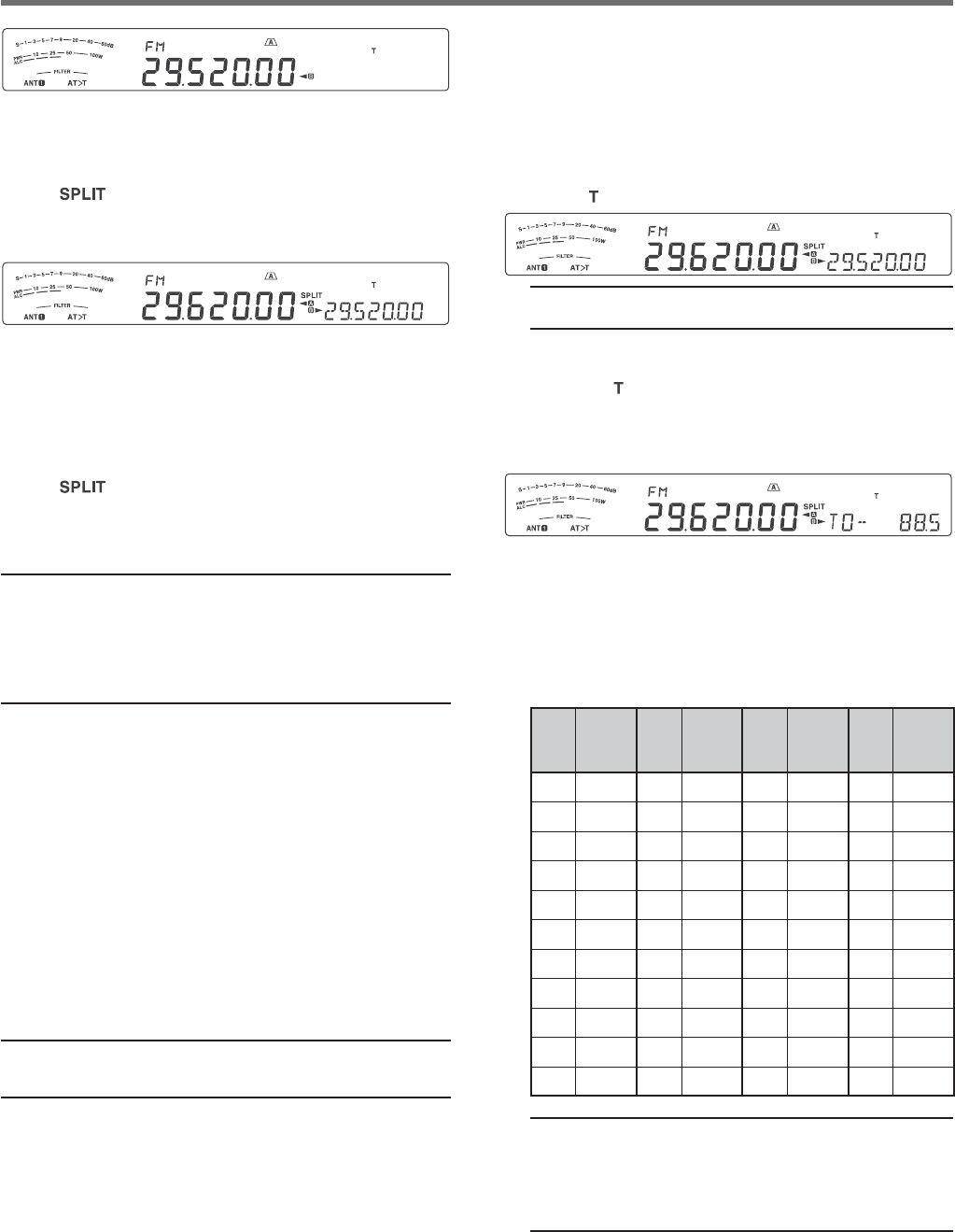
27
ENHANCED COMMUNICATIONS 6
■ Activating the Tone Function
1 Confirm that FM mode has been selected on
the VFO(s) {page 10}.
s 7HENUSING6&/SYOUMUSTSELECT&-
mode on both VFOs.
2 Press [AGC/T (SEL)].
s h ” appears.
Note: You cannot use the Tone function with the CTCSS
function.
■ Selecting a Tone Frequency
1 While “ ” appears (Tone function is ON), press
and hold [AGC/T (SEL)].
s 4HECURRENTTONEFREQUENCYAPPEARS
The default is 88.5 Hz.
2 Turn the MULTI/CH control to select the desired
tone frequency.
s 4HEAVAILABLETONEFREQUENCIESARELISTEDIN
the table below.
3 Press and hold [AGC/T (SEL)] or press [CLR]
to complete the setting.
No. Freq.
(Hz) No. Freq.
(Hz) No. Freq.
(Hz) No. Freq.
(Hz)
00 67.0 11 97.4 22 141.3 33 206.5
01 69.3 12 100.0 23 146.2 34 210.7
02 71.9 13 103.5 24 151.4 35 218.1
03 74.4 14 107.2 25 156.7 36 225.7
04 77.0 15 110.9 26 162.2 37 229.1
05 79.7 16 114.8 27 167.9 38 233.6
06 82.5 17 118.8 28 173.8 39 241.8
07 85.4 18 123.0 29 179.9 40 250.3
08 88.5 19 127.3 30 186.2 41 254.1
09 91.5 20 131.8 31 192.8 42 1750
10 94.8 21 136.5 32 203.5 -- --
Note:
◆ You can select a tone frequency independent of a
CTCSS frequency.
◆ When 1750 Hz is selected, the transceiver sends a
500 ms tone burst each time transmission starts. You
cannot transmit 1750 Hz tone manually.
s 4OQUITTHE3UBTONEFUNCTIONPRESS[AGC/T (SEL)]
twice.
7 Press [SPLIT].
s h ” appears.
8 Press [A/B (A=B)] to return to the original
reception frequency.
9 Press Mic [PTT] to transmit.
s 4HE6&/CHANGESTOTHEOTHER6&/TOTRANSMIT
s %ACHTIMEYOUPRESS[A/B (A=B)], the reception
and transmission frequencies are swapped.
10 Press [SPLIT] to quit split-frequency operation.
s h ” disappears.
The data that you select in steps 1 to 8 can be stored
in memory. Refer to “Split-Frequency Channels” {page
43}.
Note:
◆ When operating through a repeater, over deviation caused
by speaking too loudly into the microphone can cause your
signal to “talk-off” (break up) through the repeater.
◆ To check the tone frequency stored in a memory channel,
recall the desired memory channel and press [AGC/T
(SEL)].
TRANSMITTING A TONE
In general, FM repeaters require the transceiver to
transmit a sub-audible tone to prevent other repeaters
on the same frequency from locking each other up.
The required tone frequency differs among repeaters.
Repeaters also differ in their requirements for either
continuous or burst tones. For the appropriate
selections for your accessible repeaters, consult your
local repeater reference.
After completing the tone settings, pressing and
holding Mic [PTT] causes the transceiver to transmit
the selected tone. If you have selected a 1750 Hz
tone, the transceiver sends a 500 ms tone burst each
time transmission starts.
Note: If you store tone settings in a memory channel, you need
NOTREPROGRAMEACHTIME2EFERTOh-%-/29&%!452%3v
{page 43}.
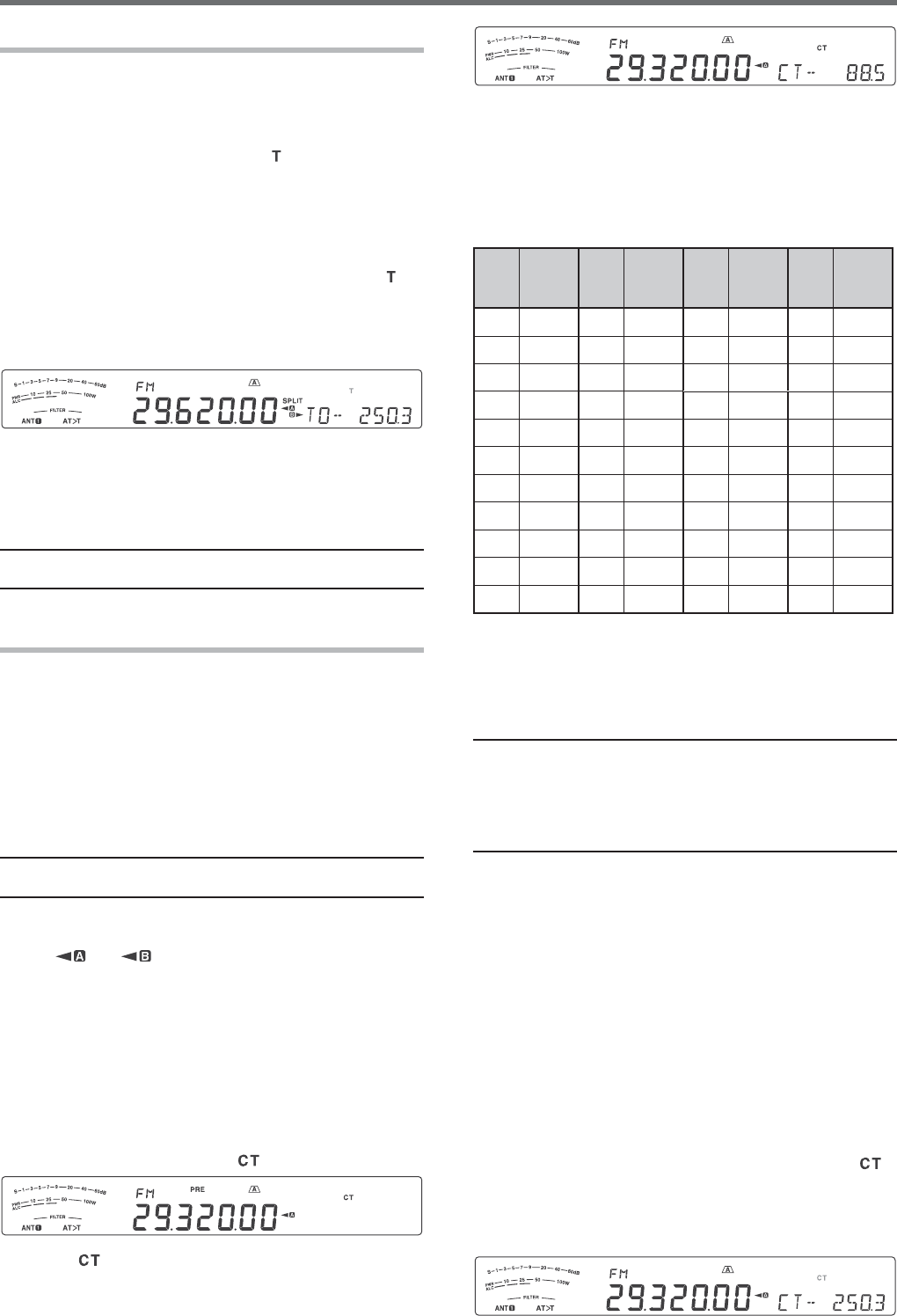
28
6 ENHANCED COMMUNICATIONS
8 Turn the MULTI/CH control to select the
appropriate CTCSS frequency.
s 4HESELECTABLE#4#33FREQUENCIESARELISTEDIN
the table below.
9 Press and hold [AGC/T (SEL)] or press [CLR] to
complete the setting.
No. Freq.
(Hz) No. Freq.
(Hz) No. Freq.
(Hz) No. Freq.
(Hz)
00 67.0 11 97.4 22 141.3 33 206.5
01 69.3 12 100.0 23 146.2 34 210.7
02 71.9 13 103.5 24 151.4 35 218.1
03 74.4 14 107.2 25 156.7 36 225.7
04 77.0 15 110.9 26 162.2 37 229.1
05 79.7 16 114.8 27 167.9 38 233.6
06 82.5 17 118.8 28 173.8 39 241.8
07 85.4 18 123.0 29 179.9 40 250.3
08 88.5 19 127.3 30 186.2 41 254.1
09 91.5 20 131.8 31 192.8 -- --
10 94.8 21 136.5 32 203.5 -- --
You will hear calls only when the selected tone is
received. To answer the call, press and hold Mic
[PTT], then speak into the microphone.
Skip steps 7 and 8 if you have already programmed
the appropriate CTCSS frequency.
Note:
◆ When using split-frequency operation, select FM mode on
both VFOs to use CTCSS.
◆ You can select a CTCSS frequency independent of a tone
frequency.
◆ You cannot use the CTCSS function with the Tone function.
CTCSS FREQUENCY ID SCAN
This function scans through all CTCSS frequencies to
identify the incoming CTCSS frequency on a received
signal. You may find this useful when you cannot
recall the CTCSS frequency that the other persons in
your group are using.
1 While the CTCSS function is ON, press and hold
[AGC/T (SEL)].
s 4HECURRENT#4#33FREQUENCYAPPEARS
2 Press [SCAN (SG.SEL)] to activate the CTCSS
frequency ID scan.
s 7HILETHETRANSCEIVERISRECEIVINGASIGNALh ”
blinks and every CTCSS frequency is scanned.
When the CTCSS frequency is identified, the
transceiver stops scanning and the identified
frequency is displayed.
TONE FREQUENCY ID SCAN
This function scans through all tone frequencies to
identify the incoming tone frequency on a received
signal. You may find this useful when you do not know
the tone frequency that the repeater uses.
1 While the Tone function is ON (“ ” is visible), press
and hold [AGC/T (SEL)].
s 4HECURRENTTONEFREQUENCYAPPEARS
2 Press [SCAN (SG.SEL)] to activate the Tone
frequency ID scan.
s 7HILETHETRANSCEIVERISRECEIVINGASIGNALh ”
blinks and every tone frequency is scanned.
When the tone frequency is identified, the
transceiver stops scanning and the identified
frequency is displayed.
s 0RESS[SCAN (SG.SEL)] or [CLR] to stop
scanning while the tone frequency ID scan is
active.
s 0RESS[SCAN (SG.SEL)] again to resume
scanning.
Note: Received signals are audible while scanning is in
progress.
FM CTCSS OPERATION
You may sometimes want to hear calls only from
specific persons. When using FM mode, the
Continuous Tone Coded Squelch System (CTCSS)
allows you to ignore (not hear) unwanted calls from
other persons who are using the same frequency.
A CTCSS tone is sub-audible and is selectable from
among the 42 tone frequencies. Select the same
CTCSS tone as the other stations in your group. You
will not hear calls from stations other than those using
the same CTCSS tone.
Note: CTCSS does not cause your conversation to be private.
It only relieves you from listening to unwanted conversations.
1 Press [A/B (A=B)] to select VFO A or VFO B.
s h ” or “ ” appears to show which VFO is
selected.
2 Select the 29 MHz band or the 51-54 MHz band
using [28 (9)] or [50 (0)].
3 Select the desired frequency with the Tuning
control or MULTI/CH control.
4 Press [FM/AM (FM-N)] to select FM mode.
5 Turn the SQL control to adjust the squelch.
6 Press [AGC/T (SEL)] until “ ” appears.
7 While “ ” is visible, press and hold [AGC/T
(SEL)].
s 4HECURRENT#4#33FREQUENCYAPPEARSDEFAULT
is 88.5 Hz).

29
ENHANCED COMMUNICATIONS 6
s 0RESS[SCAN (SG.SEL)] or [CLR] to stop
scanning while the CTCSS frequency ID scan is
active.
s 0RESS[SCAN (SG.SEL)] again to resume
scanning.
Note: Received signals are audible while scanning is in
progress.
CROSS TONE
Use this feature when using different uplink and
downlink tones to access a repeater. You can set a
transmission Tone frequency and reception CTCSS
frequency to different frequencies.
To set the transmission tone:
1 Press [A/B (A=B)] to select VFO A or VFO B.
2 Select your desired transmission frequency.
3 Press [FM/AM (FM-N)] to select FM.
4 Press [AGC/T (SEL)] until “ ” appears.
5 Press and hold [AGC/T (SEL)], then turn the
MULTI/CH control to select your desired Tone
frequency.
6 Press and hold [AGC/T (SEL)] or press [CLR] to
complete the setting.
To set the reception tone:
1 Press [A/B (A=B)] to select the other VFO.
2 Select your desired reception frequency.
3 Press [FM/AM (FM-N)] to select FM.
4 Press [AGC/T (SEL)] until “ ” appears.
5 Press and hold [AGC/T (SEL)], then turn the
MULTI/CH control to select your desired CTCSS
frequency.
6 Press and hold [AGC/T (SEL)] or press [CLR] to
complete the setting.
To set the Cross tone:
1 Press [SPLIT].
s h30,)4vAPPEARSONTHEDISPLAY
2 Press [AGC/T (SEL)] until “ ” appears.
Note: hen the cross tone function is ON, the Tone and CTCSS
frequency cannot be changed. To change the Tone or CTCSS
frequency, press [AGC/T (SEL)] to turn Tone or CTCSS ON,
then change the setting.