JVC KENWOOD 412900 144/430 MHz FM Dual Bander User Manual
JVC KENWOOD Corporation 144/430 MHz FM Dual Bander
UserManual.wiki
>
JVC KENWOOD
>
412900 User Manual
User Manual
Navigation menu
Upload a User Manual
Namespaces
Wiki Guide
HTML
PDF
Info
Views
User Manual
Discussion / Help
Navigation

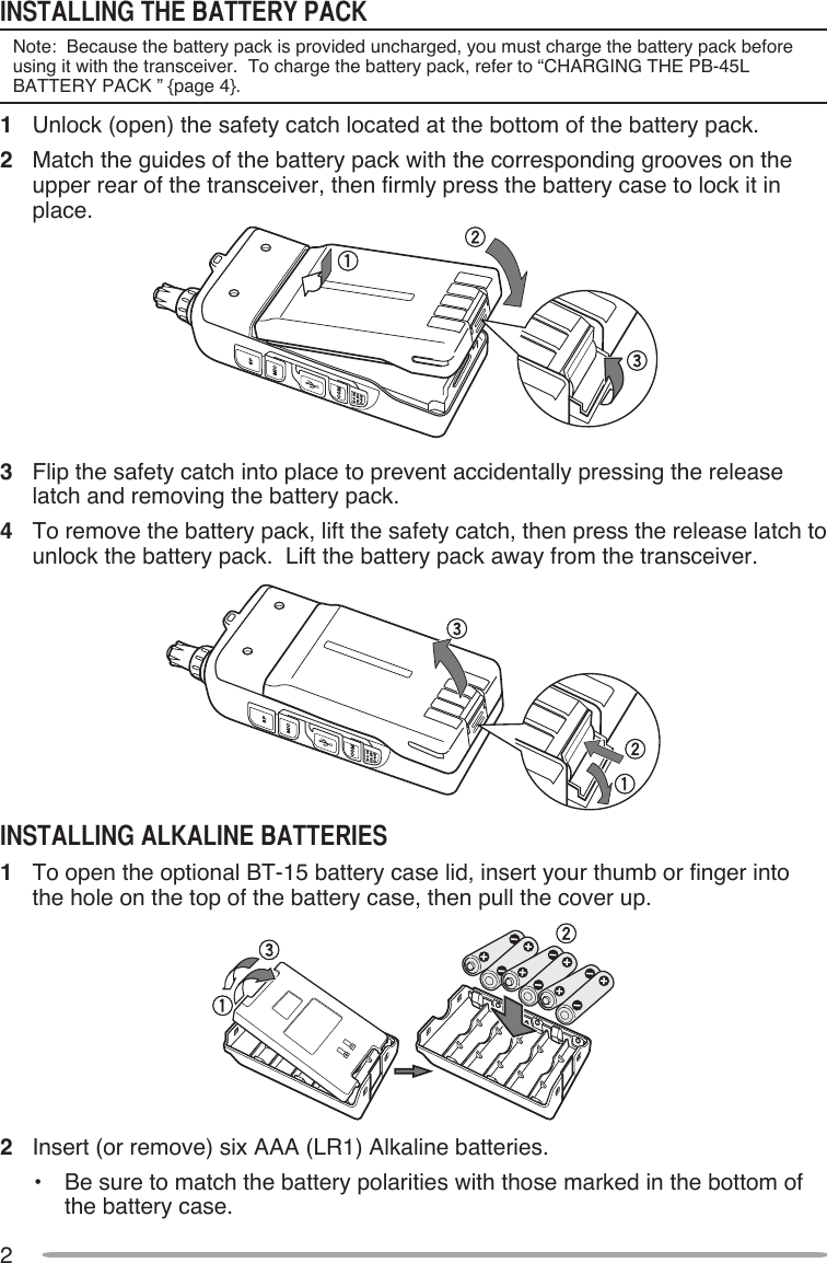
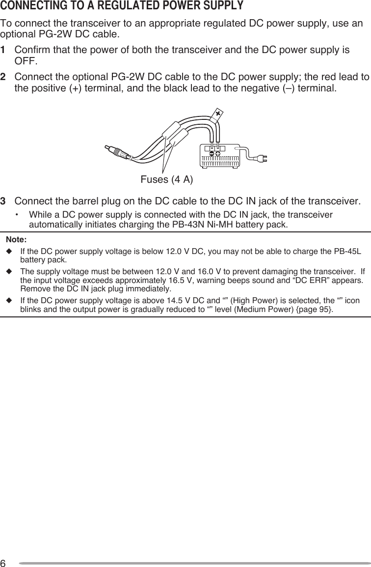
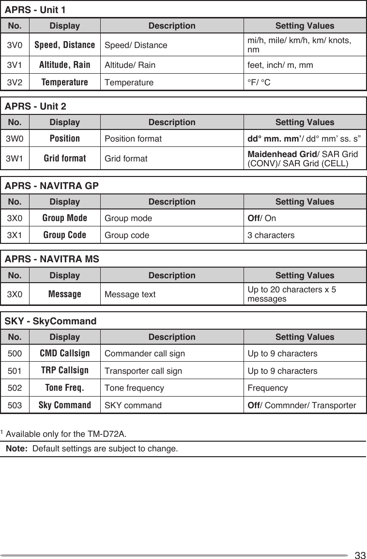
![Thank YouWe are grateful you decided to purchase this Kenwood FM transceiver. Kenwood always provides Amateur Radio products which surprise and excite serious hobbyists. This transceiver is no exception. Kenwood believes that this product will satisfy your requirements for both voice and data communications.The models listed below are covered by this manual.TH-D72A: 144/440 MHz FM Dual Bander (The Americas)TH-D72E: 144/430 MHz FM Dual Bander (Europe)FeaTuresThis transceiver has the following main features:• A built-in GPS receiver unit.• A built-in TNC which conforms to the AX.25 protocol. With a portable computer, it allows you to easily enjoy Packet operation.• Includes a program for dealing with data formats supported by Automatic Packet/ Position Reporting System (APRS®).• Contains a total of 1000 Memory channels to program frequencies and other various data. Each Memory channel can be named using up to 8 alphanumeric characters.• Continuous Tone Coded Squelch System (CTCSS) or Digital Code Squelch (DCS) rejects unwanted calls from other stations.WriTing ConvenTions FolloWed in This ManualThe writing conventions described below have been followed to simplify instructions and avoid unnecessary repetition.Instruction ActionPress [KEY]. Momentarily press KEY.Press [KEY] (1s). Press and hold KEY for 1 second or longer.Press [KEY1], [KEY2]. Press KEY1 momentarily, release KEY1, then press KEY2.Press [F], [KEY]. Press the F key to enter Function mode, then press KEY to access its secondary function.Press [KEY] + Power ON. With the transceiver power OFF, press and hold KEY while turning the transceiver power ON.Information on Disposal of Old Electrical and Electronic Equipment and Batteries (applicable for EU countries that have adopted separate waste collection systems)Products and batteries with the symbol (crossed-out wheeled bin) cannot be disposed as household waste. Old electrical and electronic equipment and batteries should be recycled at a facility capable of handling these items and their waste byproducts. Contact your local authority for details in locating a recycle facility nearest to you. Proper recycling and waste disposal will help conserve resources whilst preventing detrimental effects on our health and the environment.](https://usermanual.wiki/JVC-KENWOOD/412900/User-Guide-1362262-Page-4.png)
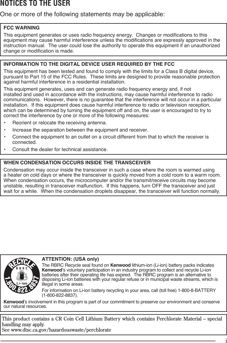
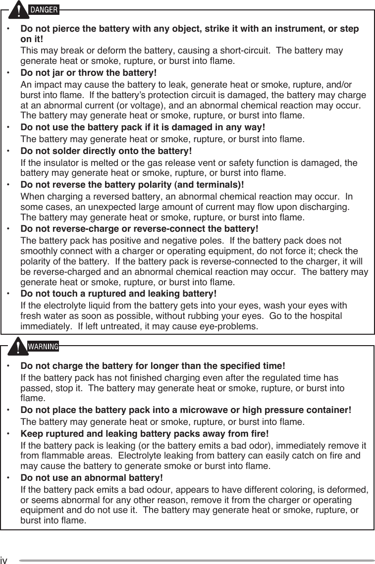
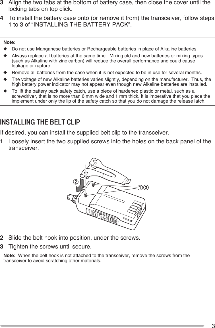
![7cONNEcTINg TO A PcThe USB connector allows you to directly connect to a computer by using a supplied USB. You must use the ARUA-10 software to control the USB audio system line of the PC, available at:http://www.kenwood.com/i/products/info/amateur/software_download.htmlUSB terminalSupplied USB cablePCcONNEcTINg TO AN ExTANAl gPS uNIT OR WEAThER STATIONThe GPS jack on this transceiver accepts a 2.5 mm (1/10") 3-conductor plug. If necessary, use the cable (service part: E30-3400-XX) to modify the cable end of extanal GPS receiver or Weather Station.• Use a GPS receiver which conforms to the NMEA-0183 format and is compatible with RS-232C signal polarity output at the below mentioned levels. [Low level: less then +0.5 V / High level: more then +3 V] You cannot use GPS receivers with USB-type connections.5 3 2GNDRXDTXDShield (to GND on GPS/ WX)Red (to DATA OUT on GPS/ WX)White (to DATA IN on GPS/ WX)Extanal GPS receiverCOM terminalWeather Station](https://usermanual.wiki/JVC-KENWOOD/412900/User-Guide-1362262-Page-17.png)
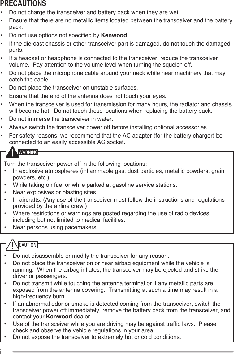
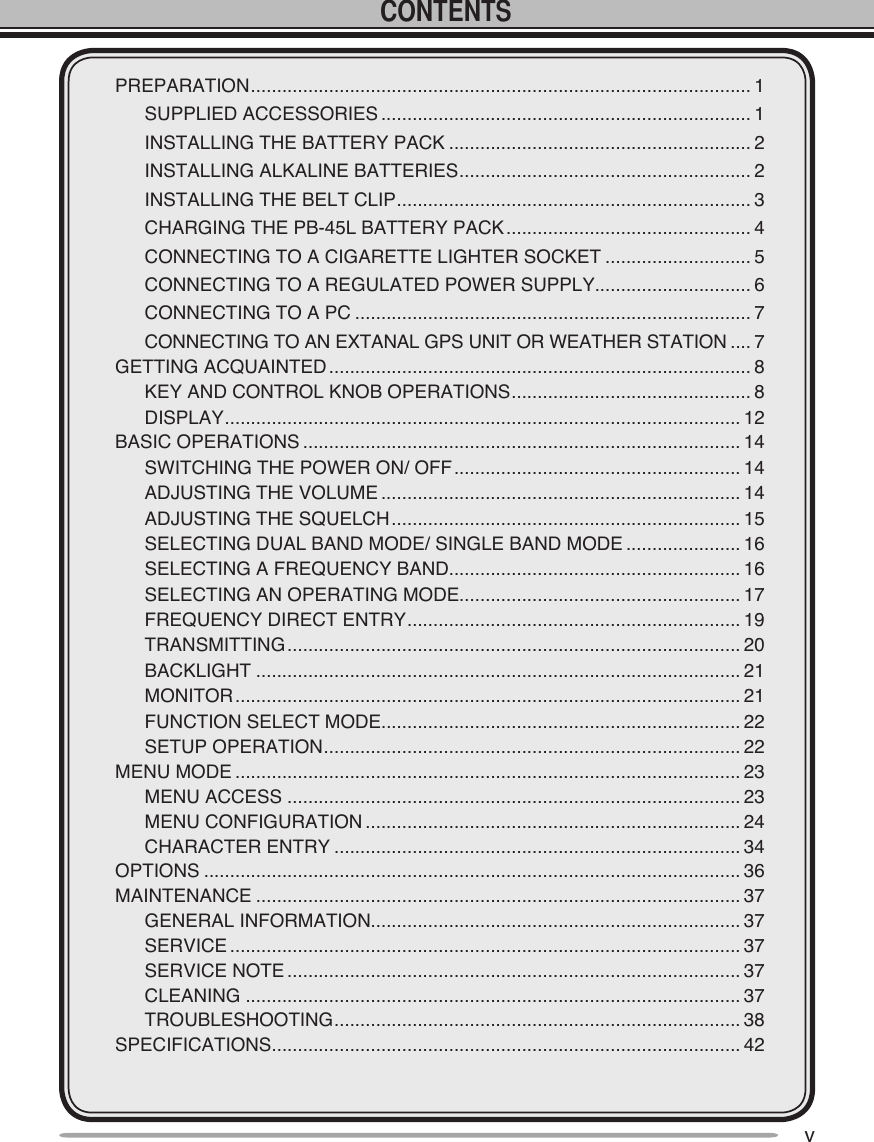
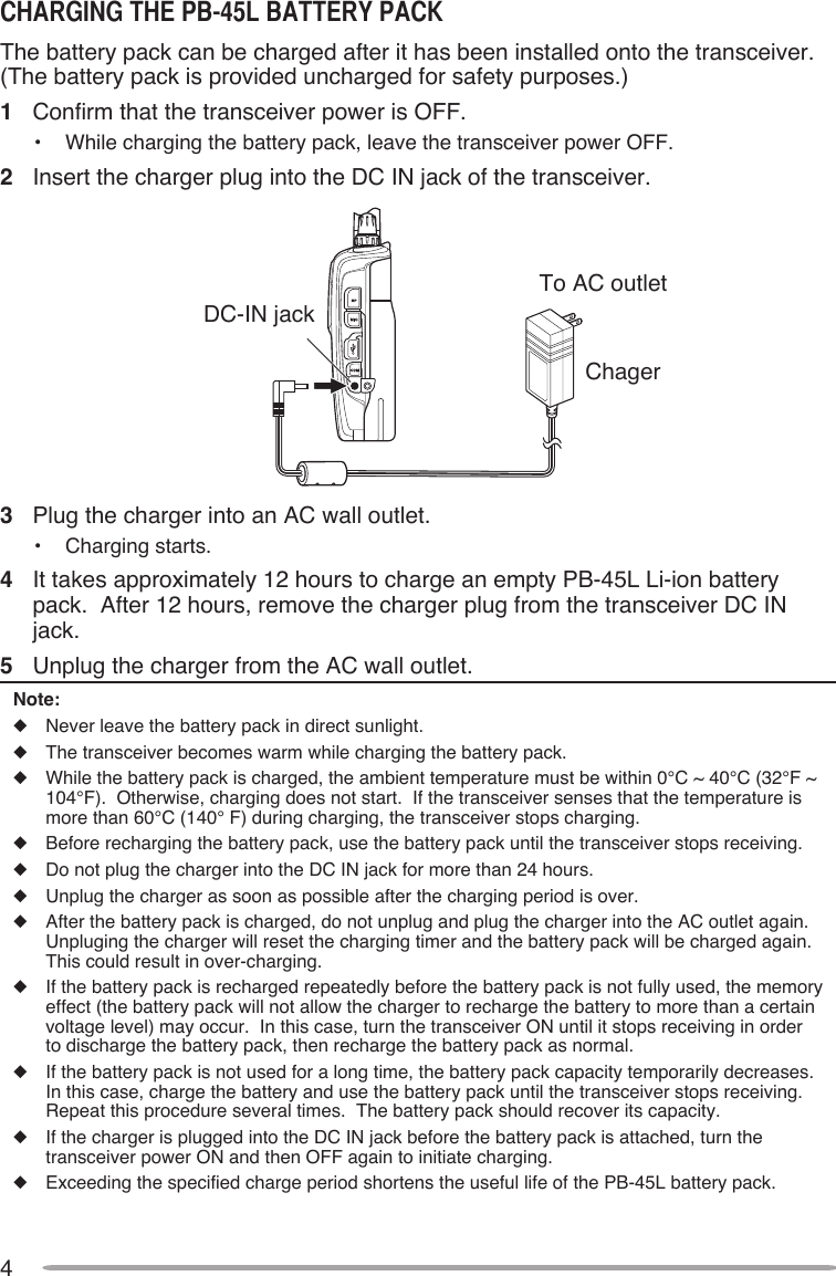
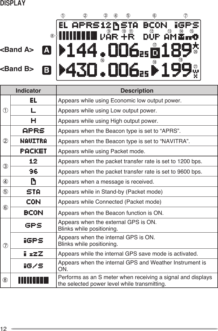
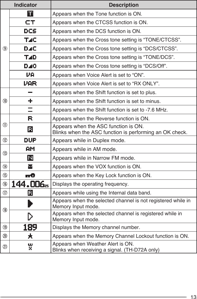
![8GETTING ACQUAINTED Press [ ] to turn the transceiver power ON and OFF. Tuning ControlRotate the Tuning control to select an operating frequency, Memory channel, Menu number, setting value and change the scan direction, etc. VOL ControlRotate the VOL control to adjust the speaker volume. [PTT]Press and hold [PTT], then speak into the microphone to transmit. [LAMP] Press [LAMP] to illuminate the display and keys.Press [F], [LAMP] to keep the light ON continuously. [MONI] Press and hold [MONI] to unmute the speaker in order to monitor signals. Release [MONI] to return to normal operation. KEy AND CONTROL KNOB OpERATIONs](https://usermanual.wiki/JVC-KENWOOD/412900/User-Guide-1362262-Page-18.png)
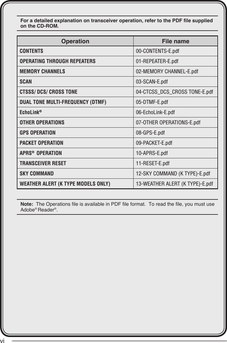
![9 [ ], [ ] Press [ ] or [ ] to select an operating frequency, Memory channel, Menu number, setting value or to change the scan direction, etc. The [ ]/ [ ] keys function in the exact same way as the Tuning control. These keys change frequencies, memory channels, or other selections, depending on the current transceiver mode.[ OK] Press [ OK] to move to the next step or to complete the setting in various selection modes such as Function Select or Menu mode.[ESC ]Press [ESC ] to move back to the previous step or to quit the setting in various selection modes such as Function Select or Menu mode.[A/B] Press [A/B] to select operation band A or B. Press [F], [A/B] to select a frequency band.[MENU] Press [MENU] to enter Menu mode. Press [F], [MENU] to cycle the transmit output power between: High Power –> Low Power –> Economic Low Power.[F]Press [F] to enter Function mode.Press [F] (1s) to turn the transceiver key lock function ON and OFF.[VFO]Press [VFO] to enter VFO mode, then press [ ]/[ ] or rotate the Tuning control to select an operating frequency.Press [F], [MENU] to copy the current Memory channel or Call channel to the VFO (memory shift).[MR]Press [MR] to enter Memory Channel mode, then press [ ]/[ ] or rotate the Tuning control to select a Memory channel. Select a Memory channel, then press [F], [MR] to store the current operating frequency in the Memory channel.[CALL]Press [CALL] to select the Call channel. Press [F], [CALL] to store the current operating frequency to the Call channel.](https://usermanual.wiki/JVC-KENWOOD/412900/User-Guide-1362262-Page-19.png)
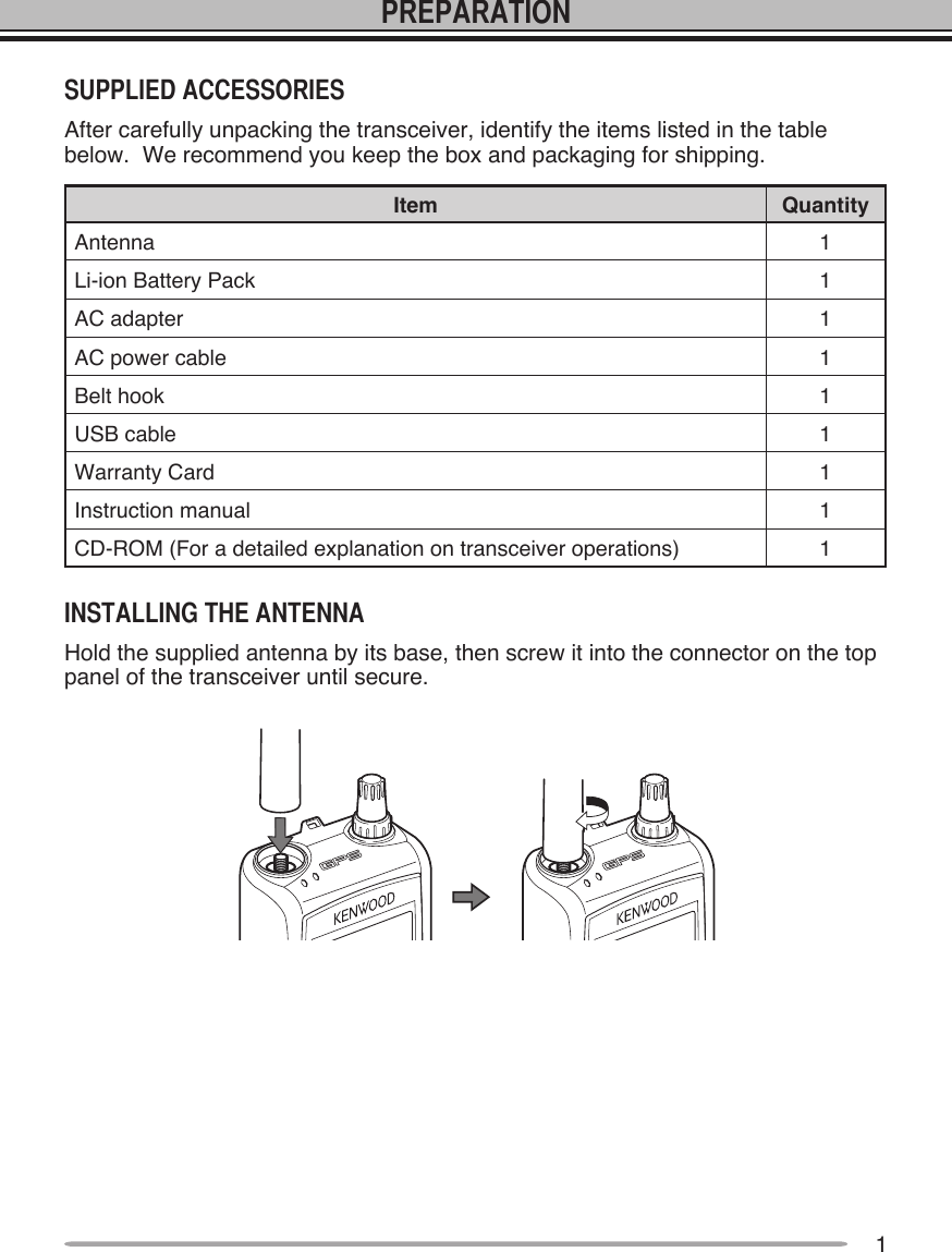
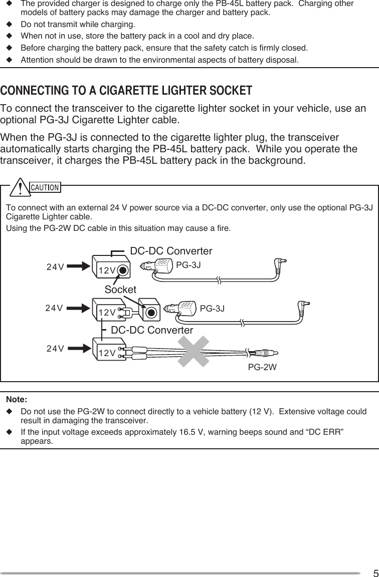
![1012 Keypad[MARK] (1)Press [MARK] to display the Mark Way point list <APRS>.Press [MARK] (1s) to enter the Mark Way point registration mode <APRS>.Press [F], [MARK] to turn the internal GPS function ON or OFF.[TNC] (2)Press [TNC] to turn the built-in TNC ON and the APRS (or NAVITRA) mode ON.• Each time you press [TNC], the mode cycles through the following: APRS (or NAVITRA) mode ON >> PACKET mode ON >> TNC OFF.• When the built-in TNC turns on, “OPENING TNC” appears on the display.• When “OPENING TNC” appears on the display, the mode cannot be changed.Press [F], [TNC] to turn the Tracking Log function ON or OFF <APRS>.[POS] (3)Press [POS] to display your “My position” (using the internal GPS) or to enter the Position registration mode (not using the internal GPS) <APRS>.Press [F], [POS] to enter the My Weather mode <APRS>.[MSG] (4)Press [MSG] to display the Message list <APRS>.Press [F], [MSG] to enter the New Message input mode <APRS>.](https://usermanual.wiki/JVC-KENWOOD/412900/User-Guide-1362262-Page-20.png)
![11[LIST] (5)Press [LIST] to display the Station list <APRS>.Press [F], [LIST] to display the DX Cluster list <APRS>.[BCON] (6)Press [BCON] to enter the Beacon Transmit mode (TX Beacon method is Manual) or turn the Beacon function ON or OFF (TX Beacon method is other then Manual) <APRS>.Press [F], [BCON] to enter the Quick Beacon mode <APRS>.[REV] (7)Press [REV] to turn the Reverse function ON or OFF. Press [REV] (1s) to turn the Automatic Simplex Checker ON.Press [F], [REV] to enter the Vice Alert function setup mode <APRS>.[TONE] (8)Press [TONE] to turn the Tone function ON.• Each time you press [TONE], the function cycles through the following: Tone ON >> CTCSS ON >> DCS ON >> Cross Tone ON >> OFF.Press [F], [TONE] to enter the Tone frequency, CTCSS frequency, DCS code, or Cross Tone setup mode.Press [F], [TONE] (1s) to start the Tone frequency ID, CTCSS frequency ID, or DCS code ID scan.[PF] (9)Press [PF] to activate its programmable function. The default function is “Weather Channel” (TH-D72A)/ “Memory Name <-> Frequency” (TH-D72E).[MHz] ( )Press [MHz] to enter the Offset Direction selection mode. • Each time you press [MHz], the offset direction cycles through the following: plus (+) direction –> minus (–) direction –> –7.6 MHz (TH-D72E only) –> OFF.Press [MHz] (1s) to start the MHz scan.Press [F], [MHz] to enter Offset Direction setup mode.[DUAL] (0)Press [DUAL] to switch the Single band mode and Dual band mode.Press [F], [DUAL] to turn the Full duplex function ON or OFF.[ENT] (#)Press [ENT] to enter Frequency or Channel number entry mode.Press [F], [ENT] to enter Frequency step setup mode.](https://usermanual.wiki/JVC-KENWOOD/412900/User-Guide-1362262-Page-21.png)
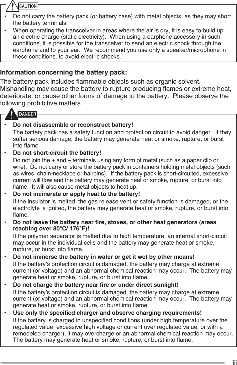
![14Press the [ ] switch to switch the transceiver ON.• The power on message momentarily appears on the display.• If the transceiver power on password has been activated {Menu No.100}, you must first enter your password before you can operate the transceiver.Press the [ ] switch again to switch the transceiver OFF.Rotate the VOL control of your selected band clockwise to increase the volume and counterclockwise to decrease the volume.Note: Some functions of this transceiver, such as the beep, have their own volume settings. Adjust those settings to your desired values.](https://usermanual.wiki/JVC-KENWOOD/412900/User-Guide-1362262-Page-24.png)
![15Squelch is used to mute the speaker when no signals are present. With the squelch level set correctly, you will hear sound only while actually receiving a signal. The higher the squelch level selected, the stronger the signals must be in order to hear them.1 Press [F], [MONI].• The squelch level appears on the display.2 Press [ ]/[ ] or rotate the Tuning control of your selected band, when no signals are present, and select the squelch level at which the background noise is just eliminated.Press [A/B] to select operating band A or B.](https://usermanual.wiki/JVC-KENWOOD/412900/User-Guide-1362262-Page-25.png)
![16You can switch the transceiver between dual band operation and single band operation.1 Select your desired band (A or B).2 Press [DUAL].• Each time you press [DUAL], the transceiver switches between Single band mode and Dual band mode.Dual band mode:Single band mode (band A only): Single band mode (band B only):You can change the default frequency bands for bands A and B.1 Select your desired band (A or B).2 Press [F], [A/B].• Each time you press [F], [A/B], you cycle to the next frequency band.• When masking a band, you are restricted to using only the selectable band.• When receiving 2 signals on the same band, the image interference, sensitivity, etc., performance will decrease.• Band A: 144 >> 430/440 (MHz).• Band B: 118 >> 144 >> 300 >> 430/440 (MHz).Note: The TH-D72E uses the 430 MHz band and the TH-D72A uses the 440 MHz band.](https://usermanual.wiki/JVC-KENWOOD/412900/User-Guide-1362262-Page-26.png)
![17Frequency ranges:• 118 MHz: 118 ~ 135.995 MHz• 144 MHz: 144 ~ 173.995 MHz• 300 MHz: 320 ~ 399.995 MHz• 430/440 MHz: 430 ~ 523.995 MHzThere are 3 operating modes available to choose from: VFO mode, Memory Channel mode, and Call Channel mode.VFO mode allows you to manually change the operating frequency.1 Press [VFO] to enter VFO mode.2 Rotate the Tuning control to select your desired operating frequency.• You can also select a frequency by using the [ ]/[ ] keys.• The default step frequency for the Tuning control varies according to the model and operating band:Model 144 MHz 430/440 MHzTH-D72A 5 kHz 25 kHzTH-D72E 12.5 kHz 25 kHz• To adjust the frequency by a larger amount, press [MHz] to enter MHz mode, then rotate the Tuning control to adjust the frequency in steps of 1 MHz. Press [MHz] again to exit MHz mode and adjust the frequency using the normal step frequency.](https://usermanual.wiki/JVC-KENWOOD/412900/User-Guide-1362262-Page-27.png)
![18Memory Channel mode allows you to quickly select a frequently used frequency and related data which you have saved in the transceiver memory.1 Press [MR] to enter Memory Channel mode.• The Memory channel number appears on the display.2 Rotate the Tuning control to select your desired Memory channel.• You can also select a Memory channel by using the the [ ]/[ ] keys.Call Channel mode allows you to quickly select a preset channel to allow immediate calls on that frequency. The Call channel can be conveniently used as an emergency channel within your group.1 Select your desired band (A or B).• The Call channel has a dedicated frequency for both bands A and B. The default frequency for band A is 144 MHz. The default frequency for band B is 430/440 MHz.2 Press [CALL] to enter Call Channel mode.• “C” appears on the display.](https://usermanual.wiki/JVC-KENWOOD/412900/User-Guide-1362262-Page-28.png)
![19If the desired operating frequency is far from the current frequency, using the keypad is the quickest way to change the frequency. 1 Press [A/B] to select band A or B, then press [VFO] or [CALL].2 Press [ENT].• The Direct Frequency Entry display appears.3 Press the number keys ([0] ~ [9]) to enter your desired frequency.4 To set the entered frequency, press [ENT] or [VFO].• Pressing [ENT] before entering all of the digits will set the remaining digits to 0.• Pressing [VFO] before entering all of the digits will leave the remaining digits at their previous values.• Entering all digits for a frequency will automatically set the frequency without pressing [ENT] or [VFO].• If you need to only change the MHz digit, press [MHz], then enter the new value.](https://usermanual.wiki/JVC-KENWOOD/412900/User-Guide-1362262-Page-29.png)
![201 Select your desired band and frequency/channel.2 Press and hold the microphone [PTT] switch and speak into the microphone to transmit.• The TX-RX LED lights red for the selected transmit band and the RF power meter appear on the display. The RF power meter shows the relative transmit output power.• “H”, “L”, or “EL” appear on the display, depending on the output power you have selected.• Speak into the microphone in your normal voice, while keeping the microphone approximately 5 cm (2 inches) from your mouth. Speaking too close to the microphone or too loudly may increase distortion and reduce intelligibility of your signal at the receiving station.3 When you finish speaking, release the [PTT] switch.Note: When the transceiver overheats because of ambient high temperature or continuous transmission, the protective circuit may function to lower the transmit output power. Selecting a low transmit power is a wise method to reduce battery consumption, if communication is still reliable. You can program separate transmit power settings for band A and B.Press [F], [MENU] to select high (default), low, or economic low power (lowest).• “H”, “L”, or “EL” appears to show the current selection.](https://usermanual.wiki/JVC-KENWOOD/412900/User-Guide-1362262-Page-30.png)
![21Press [LAMP] to illuminate the display and keys.• If no other key is pressed, the light turns OFF approximately 5 seconds after releasing [LAMP].• Press any key (including [PTT]) other than [LAMP] while the display and keys are lit to restart the 5-second timer.• Press [LAMP] while the display and keys are lit to immediately turn the light OFF.Press [F], [LAMP] to keep the light ON continuously.• The light remains ON until you press [F], [LAMP] again.Note: You can set the Display lighting time in Menu No. 101.When you are receiving while the squelch function is ON, weak signals may become intermittent.If the CTCSS or DCS function is ON, you may want to disable the squelch function temporarily to monitor the current channel activities.1 Press and hold [MONI].• The speaker is unmuted and you can monitor the signals.2 Release [MONI] to return to normal operation.](https://usermanual.wiki/JVC-KENWOOD/412900/User-Guide-1362262-Page-31.png)
![22Press [F] to enter Function Select mode. In this mode you can scroll F–0 through F–# by pressing [ ]/[ ]. After accessing the desired function, press [ OK], then press [ ]/[ ] to select the desired parameter.Pressing [F], [0] ~ [9] or [ ], [#] is a much simpler method. For example, pressing [F], [8] switches the Tone function ON or OFF. (Refer to the keypad explanations on pages 10 ~ 11.)Note: You can verify the battery capacity while in Function Select mode. Full Medium Low Very Low (recharge)Press [MENU] to enter Menu mode. In this mode you can access the desired menu item by pressing [ ]/[ ] and [ OK] or entering digits directly from the keypad (0 ~9, A, B, C, D, E ( ),and F (#) only). For further information, refer to “MENU MODE” {page 23}.](https://usermanual.wiki/JVC-KENWOOD/412900/User-Guide-1362262-Page-32.png)
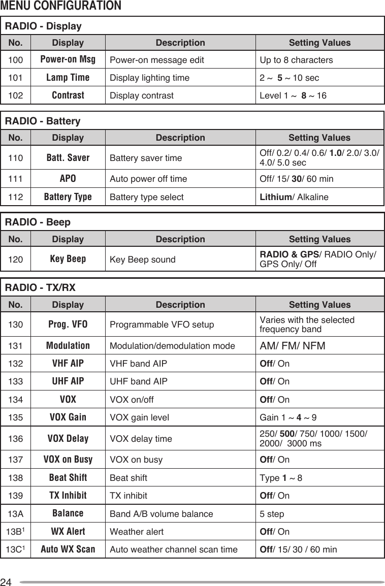
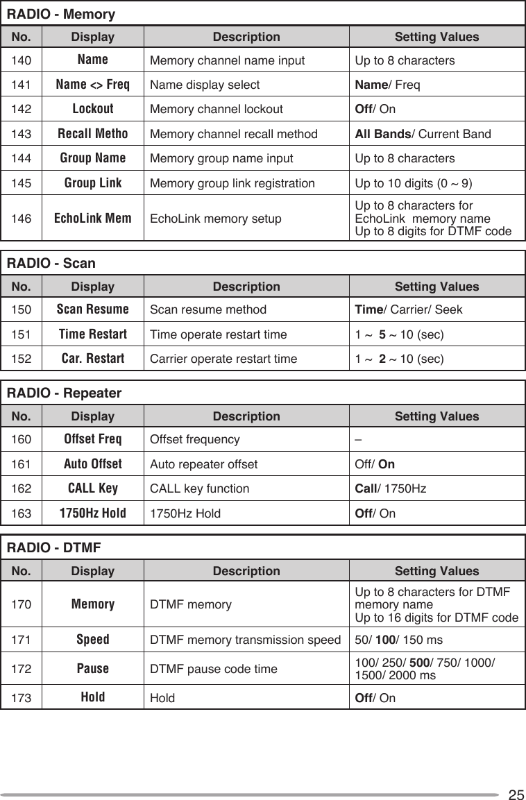
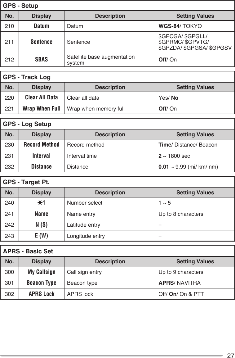
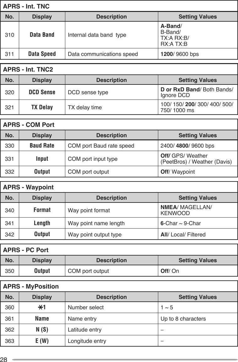
![23Many functions on this transceiver are selected or configured through the Menu instead of physical controls. Once you become familiar with the Menu system, you will appreciate the versatility it offers.1 Press [MENU] to access the Menu.• The setup category name appears on the display.2 Press [ ]/[ ] or rotate the Tuning control to select your desired category.3 Press [ OK] to set the category.• The Menu name and number appear on the display.4 Press [ ]/[ ] or rotate the Tuning control to select your desired Menu.5 Press [ OK] to set the Menu.6 Press [ ]/[ ] or rotate the Tuning control to select your desired value for the Menu.7 Press [ OK] to set the selected value.8 Repeat steps 2 to 7 to set up additional Menus.9 Press [MENU] to exit Menu mode.](https://usermanual.wiki/JVC-KENWOOD/412900/User-Guide-1362262-Page-33.png)
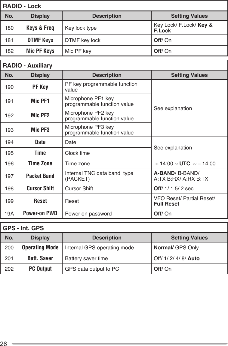
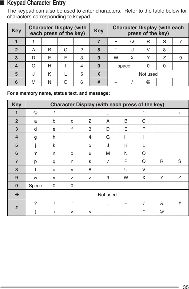
![34Certain menus require you to enter characters, such as the power on message and memory names. When character entry is required, a cursor will appear on the display.1 Press [ OK].• The cursor will blink.2 Press [ ]/[ ] or rotate the Tuning control to select your desired character.3 Press [ OK] to set the selected character.• The cursor will move to the next digit.• You can move the cursor to the left or right by pressing [ESC ] or [ OK].• You can delete the selected character by pressing [A/B (CLR)].• Press and hold [LAMP] and then press [ ]/[ ] or rotate the Tuning control to select your desired letter type. 4 Repeat steps 2 and 3 to enter the remaining characters.• Press [MENU] to exit Menu mode.Auto Cursor Shift will automatically shift the cursor to the next character after a character has been entered. This function lets you set up the time delay after character entry for the automatic cursor shift. If this function is set to OFF, you must manually shift the cursor by pressing [ OK].1 Enter Menu mode and access Menu 198.2 Set the desired shift time to Off (manual shift), 1, 1.5, or 2 sec.](https://usermanual.wiki/JVC-KENWOOD/412900/User-Guide-1362262-Page-44.png)
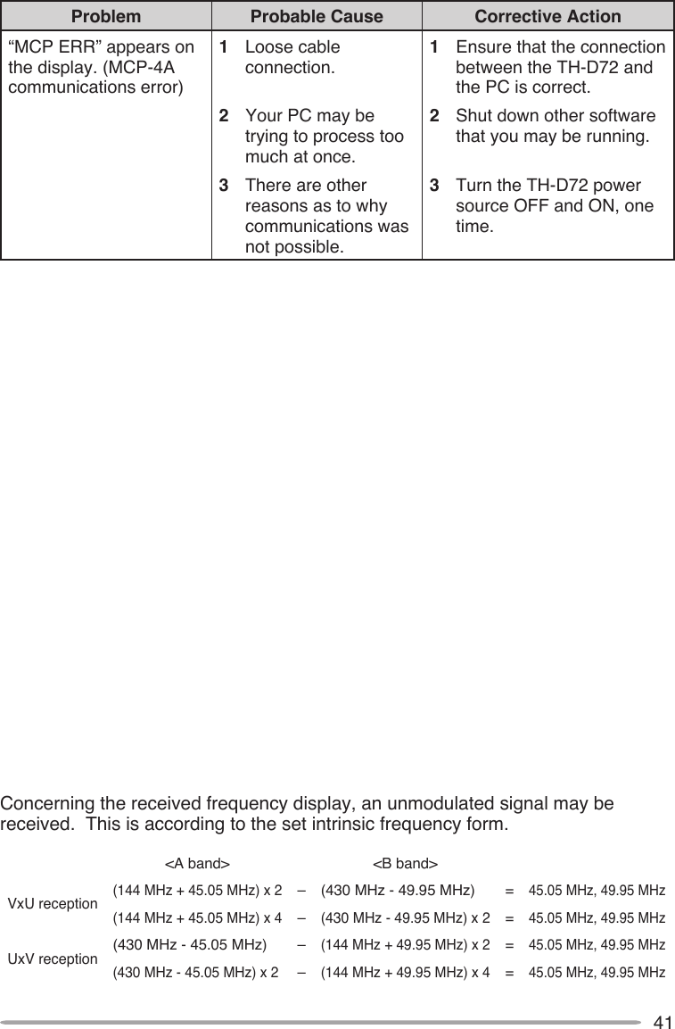
![38TROUBLESHOOTINGThe problems described in this table are commonly encountered operational malfunctions and are usually not caused by circuit failure.Problem Probable Cause Corrective ActionNothing appears on the display when the transceiver is switched ON, or the display is blinking ON and OFF.1 The battery pack is discharged.2 The DC cable or connection is bad.3 The power supply fuse is open (blown).1 Recharge the battery pack or replace the battery.2 Replace the cable. 3 Investigate the cause for the open fuse and replace the fuse.Most keys and the Tuning control do not function.1 One of the Lock functions is ON.2 The transceiver is in Channel Display mode.1 Unlock all of the Lock functions.2 With the transceiver power OFF, press [PTT] + [A/B] + Power ON to exit Channel Display mode.You cannot select the exact desired frequency using the Tuning control.Programmable VFO frequency range is too narrow.Expand the frequency range in Menu No. 130 (Prog.VFO).Memory channels cannot be selected by turning the Tuning control or by pressing [ ]/[ ].No data has been stored in any Memory channel.Store data in some Memory channels.The receiving sound volume is weak even if the signal is strong.The receiving station may be operating in narrow band FM bandwidth.Access Menu No. 131 (Modulation) to select “NFM”.Turning the VOL control does not allow you to hear audio.The selective call function (CTCSS or DCS) is ON.Turn OFF the selective call function.](https://usermanual.wiki/JVC-KENWOOD/412900/User-Guide-1362262-Page-48.png)
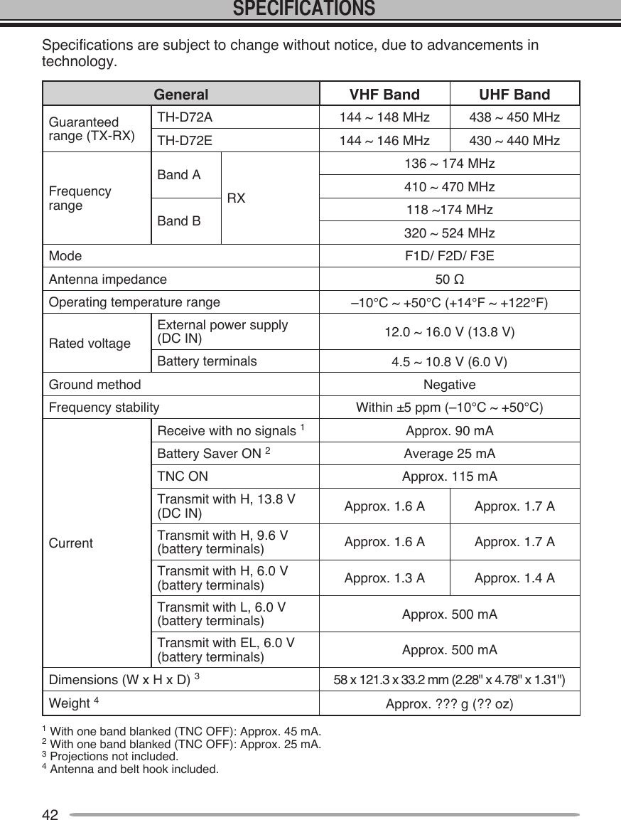
![39Problem Probable Cause Corrective ActionYou cannot transmit by pressing the PTT switch.1 You selected a frequency outside the allowable range.2 You selected a trasmit offset that places the tranmit frequency outside the limit.3 TX inhibit is ON. 4 The battery pack voltage is too low to transmit.1 Select a frequency within the allowable transmit frequency range.2 Select a proper offset direction or offset frequency. 3 Access Menu No. 139 (TX inhibit) and select “Off”.4 Charge or replace the battery pack.Repeater cannot be accessed.1 Wrong tone frequency is selected. 2 Wrong offset frequency is selected. 3 Wrong shift direction is selected. 1 Select a proper repeater access tone. 2 Access Menu No. 160 (Offset Freq) and select an appropriate offset frequency.3 Try other shift directions.DTMF tone cannot be transmitted.DTMF Lock is ON. Access Menu No. 181 (DTMF Keys) and select “Off”.Repeater does not accept your DTMF tones.DTMF tone transmission duration is too short.Access Menu No. 171 (Speed) and select “150 ms”.You cannot transmit by pressing [PTT].1 You selected a frequency outside the allowable range.2 You selected a transmit offset that places the transmit frequency outside the limit. 3 TX inhibit is ON. 4 The battery pack voltage is too low to transmit.1 Select a frequency within the allowable transmit frequency range.2 Select a proper offset direction or offset frequency. 3 Access Menu No. 139 (TX inhibit) and select “Off”.4 Change or replace the battery pack.Transceiver transmits without pressing [PTT].VOX function is ON. Access Menu No. 131 (VOX) and select “Off”.](https://usermanual.wiki/JVC-KENWOOD/412900/User-Guide-1362262-Page-49.png)
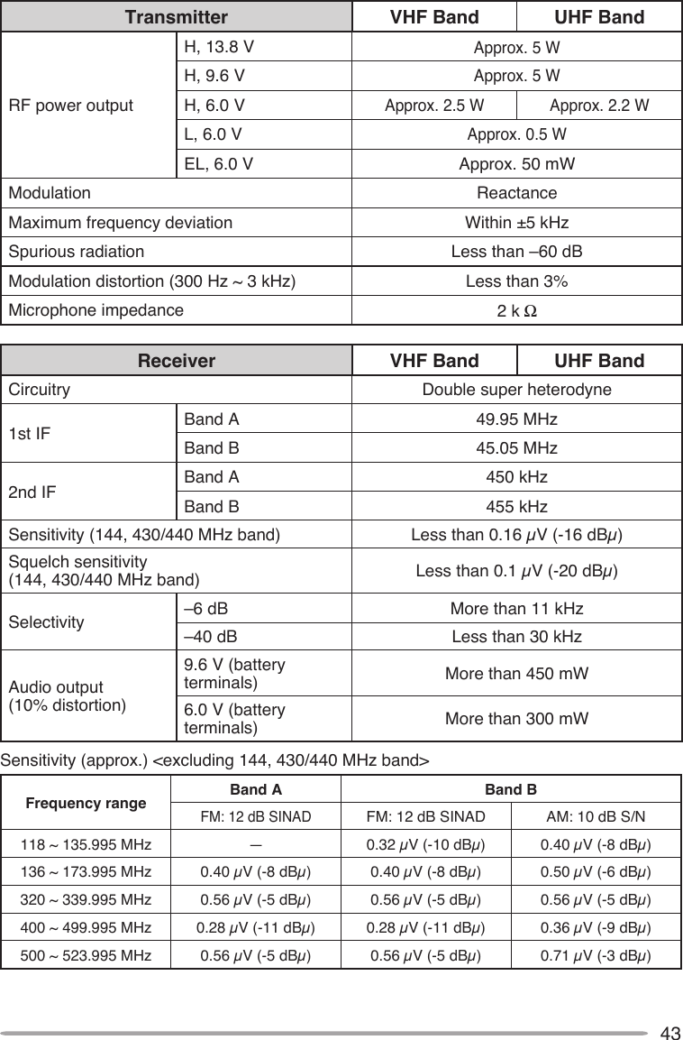
![40Problem Probable Cause Corrective ActionThe transceiver switches OFF for no apparent reason.The Automatic Power OFF (APO) function is ON.Access Menu No. 111 (APO) and select your desired time length or “OFF”.The Scan function does not resume scanning after the transceiver detects a signal.You have selected “Seek” for Menu No. 150 (Scan Resume).Select either “Time” (Time-Operated) or “Carrier” (Carrier-Operated) for Menu No. 150 (Scan Resume).Packet operation results in no connects with other stations.1 The squelch is open. 2 You did not select the same transfer rate as the target station.1 Select the correct squelch level so that the squelch is opened only when signals are present.2 Use HBAUD command to select the appropriate transfer rate.You cannot transmit any APRS data.1 Beacon is OFF. 2 The squelch is open. 3 The data band is inactive. 4 The built-in TNC is OFF.5 You selected Packet mode.1 Press [BCON] to switch Beacon ON.2 Select the correct squelch level so that the squelch is opened only when signals are present.3 If you have blanked the data band, press [A/B] or [DUAL] to active it.4 Press [TNC] to switch ON the TNC.5 Press [TNC] twice so that only “ ” appears.When using a GPS receiver, you cannot correctly transmit position data.The GPS receiver did not yet start correct measurement.Before starting correct measurement, the GPS receiver generates a low-pitch tone every 10 seconds. When starting correct measurement, it generates a high-pitch tone. (If not using the internal GPS receiver, press [F], [MARK] and select “OFF”).You cannot receive any APRS data.You did not correctly program a group code.Access Menu 3S0 and program “APK001”.](https://usermanual.wiki/JVC-KENWOOD/412900/User-Guide-1362262-Page-50.png)