JVC KENWOOD 440900 Scanning Receiver with Bluetooth User Manual TH D74A E Cover English 5 5 indd
JVC KENWOOD Corporation Scanning Receiver with Bluetooth TH D74A E Cover English 5 5 indd
UserManual.wiki
>
JVC KENWOOD
>
440900 User Manual
Users Manual
Navigation menu
Upload a User Manual
Namespaces
Wiki Guide
HTML
PDF
Info
Views
User Manual
Discussion / Help
Navigation
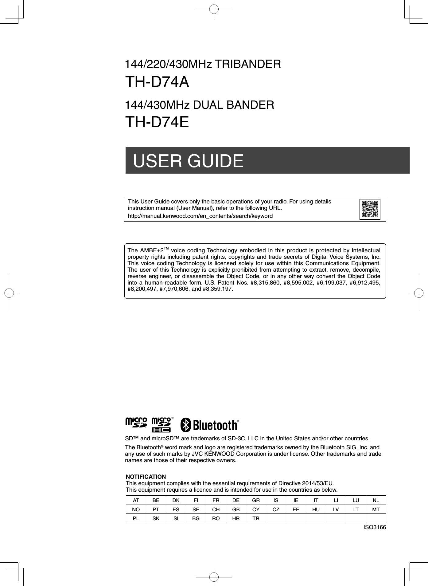
![3Thank YouWe are grateful you decided to purchase this KENWOOD Digital transceiver.The models listed below are covered by this manual.TH-D74A: 144/220/430MHz Tribander (The Americas)TH-D74E: 144/430MHz Dual Bander (Europe)FeaturesThis transceiver has the following main features:• Includes a program for dealing with data formats supported by Automatic Packet Reporting System (APRS®).• Compliant with voice/digital mode D-STAR digital amateur radio networks• Built-in GPS receiver unit.• Transfl ective color TFT Display• Weatherproof toughness meeting IP54/55 standards• Wide-band and multi-mode reception• Equipped with IF fi lter for comfortable reception (SSB/CW)• High-performance DSP-based voice processing• Compliant with Bluetooth, microSD & Micro-USBWriting Conventions Followed in this ManualThe writing conventions described below have been followed to simplify instructions and avoid unnecessary repetition.Instruction ActionPress [KEY]. Momentarily press KEY.Press [KEY] (1s).Press and hold KEY for 1 second or longer.Press [KEY1], [KEY2]. Press KEY1 momentarily, release KEY1, then press KEY2.Press [F], [KEY]. Press the F key to enter Function mode, then press KEY to access its secondary function.Press [KEY] + Power ON.With the transceiver power OFF, press and hold KEY while turning the transceiver power ON.NOTICES TO THE USEROne or more of the following statements may be applicable for this equipment.FCC WARNINGThis equipment generates or uses radio frequency energy. Changes or modifi cations to this equipment may cause harmful interference unless the modifi cations are expressly approved by the party responsible/ JVC KENWOOD. The user could lose the authority to operate this equipment if an unauthorized change or modifi cation is made.INFORMATION TO THE DIGITAL DEVICE USER REQUIRED BY THE FCCThis equipment has been tested and found to comply with the limits for a Class B digital device, pursuant to Part 15 of the FCC Rules. These limits are designed to provide reasonable protection against harmful interference in a residential installation.This equipment generates, uses and can generate radio frequency energy and, if not installed and used in accordance with the instructions, may cause harmful interference to radio communications. However, there is no guarantee that the interference will not occur in a particular installation. If this equipment does cause harmful interference to radio or television reception, which can be determined by turning the equipment off and on, the user is encouraged to try to correct the interference by one or more of the following measures: ◆Reorient or relocate the receiving antenna. ◆Increase the separation between the equipment and receiver. ◆Connect the equipment to an outlet on a circuit different from that to which the receiver is connected. ◆Consult the dealer for technical assistance.This equipment complies with FCC/IC radiation exposure limits and meets the FCC radio frequency (RF) Exposure Guidelines and RSS-102 of the IC radio frequency (RF) Exposure rules.This equipment has very low levels of RF energy that are deemed to comply without testing of specifi c absorption rate (SAR).This transmitter must not be co-located or operated in conjunction with any other antenna or transmitter.This device complies with Industry Canada license exempt RSS standard(s). Operation is subject to the following two conditions : (1) this device may not cause interference, and (2) this device must accept any interference, including interference that may cause undesired operation of the device.This product is designed for connection to an IT power distribution system.Firmware CopyrightsThe title to and ownership of copyrights for fi rmware embedded in KENWOOD product memories are reserved for JVC KENWOOD Corporation.ATTENTION: (USA and CANADA only)The RBRC Recycle seal found on KENWOODLithium-ion (Li-ion) battery packs indicatesKENWOOD’s voluntary participation in anindustry program to collect and recycle Li-ionbatteries after their operating life has expired. The RBRC program is an alternative to disposing Li-ion batteries with your regular refuse or in municipal waste streams, which is illegal in some areas.For information on Li-ion battery recycling in your area, call (toll free)1-800-8-BATTERY (1-800-822-8837).KENWOOD’s involvement in this program is part of our commitment to preserve our environment and conserve our natural resources.This product contains a CR Coin Cell Lithium Battery which contains Perchlorate Material – special handling may apply. See www.dtsc.ca.gov/hazardouswaste/perchlorateInformation on Disposal of Old Electrical and Electronic Equipment and Batteries (applicable for countries that have adopted separate waste collection systems)Products and batteries with the symbol (crossed-out wheeled bin) cannot be disposed as household waste.Old electrical and electronic equipment and batteries should be recycled at a facility capable of handling these items and their waste byproducts.Contact your local authority for details in locating a recycle facility nearest to you.Proper recycling and waste disposal will help conserve resources whilst preventing detrimental effects on our health and the environment.BEFORE STARTING](https://usermanual.wiki/JVC-KENWOOD/440900/User-Guide-3081283-Page-5.png)
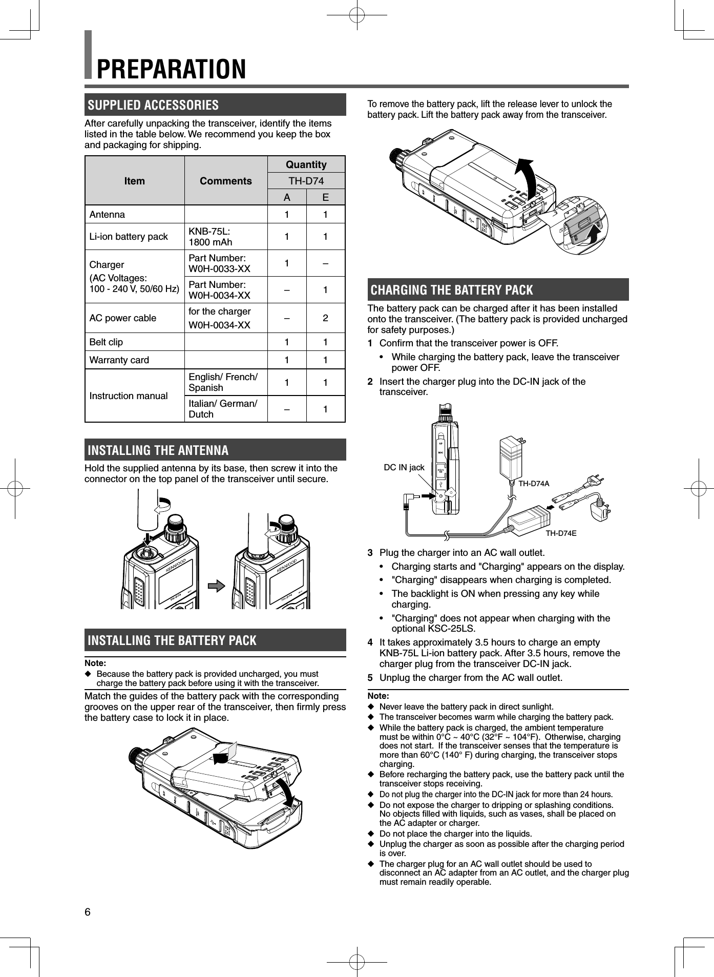
![7 ◆After the battery pack is charged, do not unplug and plug the charger into the AC outlet again. Unpluging the charger will reset the charging timer and the battery pack will be charged again. This could result in over-charging. ◆When the battery is installed on the transceiver and you are using an optional rapid battery charger, do not charge the battery from the DC-IN jack. Charging the battery from the DC-IN jack may result in overcharging the battery which can result in the shortening of the battery life cycle. ◆If the battery pack is not used for a long time, the battery pack capacity temporarily decreases. In this case, charge the battery and use the battery pack until the transceiver stops receiving. Repeat this procedure several times. The battery pack should recover its capacity. ◆If the charger is plugged into the DC-IN jack before the battery pack is attached, turn the transceiver power ON and then OFF again to initiate charging. ◆Exceeding the specifi ed charge period shortens the useful life of the KNB-75L battery pack. ◆The provided charger is designed to charge only the KNB-75L battery pack. Charging other models of battery packs may damage the charger and battery pack. ◆Do not transmit while charging. ◆When not in use, store the battery pack in a cool and dry place. ◆Before charging the battery pack, ensure that the release lever is fi rmly closed. ◆Attention should be drawn to the environmental aspects of battery disposal. ◆It takes approximately 3 hours to charge the KNB-75L with the optional KSC-25LS.Charger Error• While charging, if a problem is detected in the battery, “Charge Error !!” appears on the display.• The following conditions create charging errors:• A short in the battery is detected.• Overvoltage in the battery is detected.• When a charge error occurs, no key other than [] will function.BATTERY LIFEBefore you operate the transceiver outside using a battery pack, it is important to know how long the battery pack will last. The operating times listed in the table below are measured under the following cyclic conditions:TX: 6 seconds, RX: 6 seconds, Stand-by: 48 secondsWe recommend you carry extra battery packs with you, in case the battery pack becomes depleted.Battery Type Output Power Operating Time/ Hours (Approx.)KNB-75LLi-ion battery packH6M8L12EL 15INSTALLING THE BELT CLIPIf desired, you can install the supplied belt clip to the transceiver.Attach the belt clip fi rmly using the two supplied M3 x 6 mm binding screws.Note: ◆Be careful not to pinch your fi ngers into the belt clip.CAUTION• Do not use glue which is designed to prevent screw loosening when installing the belt clip, as it may cause damage to the transceiver. Acrylic ester, which is contained in these glues, may crack the transceiver’s back panel.INSTALLING THE HAND STRAPIf desired, you can install the commercially available strap with suffi cient strength using the holes of the transceiver.Note: ◆If the strap is thick and does not pass through the holes, install the strap using the holes of the supplied belt clip.PREPARATION](https://usermanual.wiki/JVC-KENWOOD/440900/User-Guide-3081283-Page-9.png)
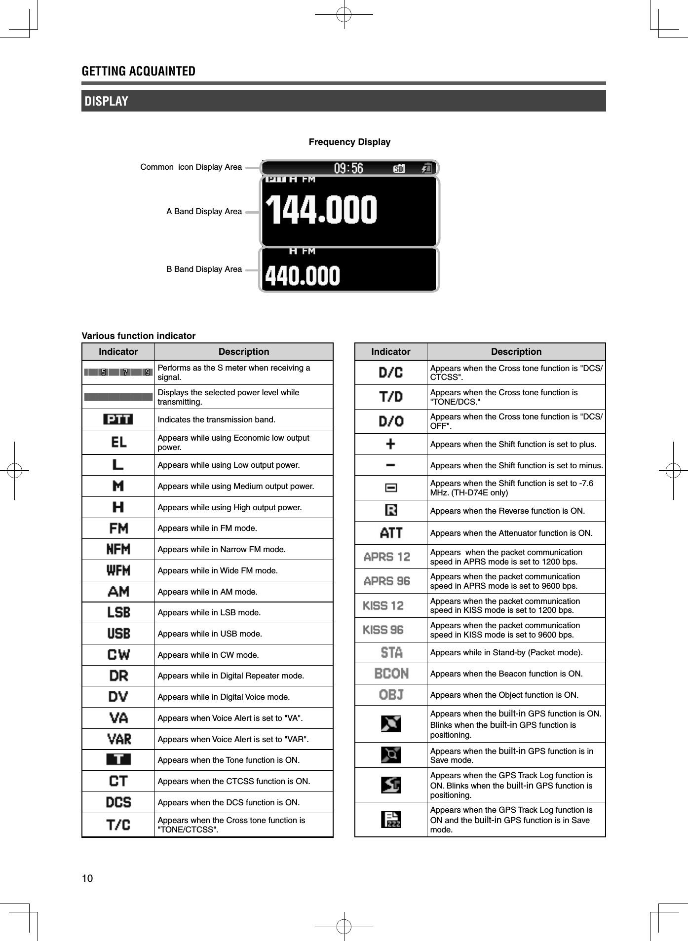
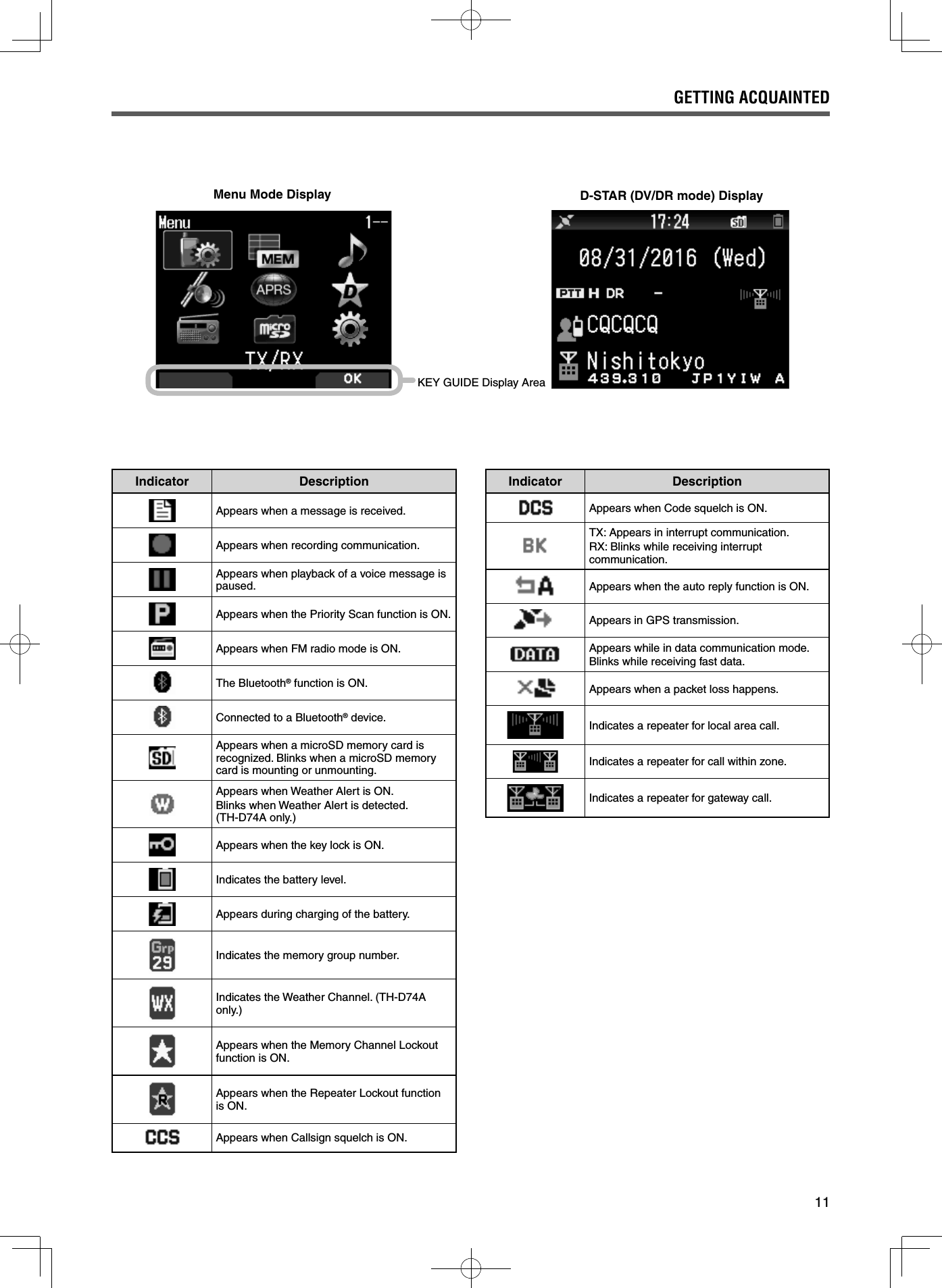
![8 [ ]Press [] (1s) to turn the transceiver power ON and OFF.Press [] to turn the backlight ON and OFF when the transceiver power is ON.The backlight turns OFF when the backlight timer elapses.When the voice guidance function is not set to OFF, the voice announces the operating states of the transceiver.When pressing [] while announcing, the voice stops. [MONI]Press and hold [MONI] to unmute the speaker in order to monitor signals.Release [MONI] to return to normal operation.Press [F], [MONI] to enter the Squelch level adjustment mode. [PTT]Press and hold [PTT], then speak into the microphone to transmit. [ENC] ControlRotate the [ENC] control to select an operating frequency, Memory channel, Menu item, setting value and change the scan direction, etc. [VOL] ControlRotate the [VOL] control to adjust the speaker volume. Multi-Scroll Key [ ], [ ]Press [] or [ ] to select an operating frequency, Memory channel, Menu item, setting value or to change the scan direction, etc.Press and hold [ ] or [ ] to change an operating frequency, Memory channel, Menu item, setting value, etc. continuously. []Press and hold [] to select a frequency band in VFO mode.Press [] to move to the next step in various setting modes. []Press and hold [] to select a frequency band in VFO mode.Press [] to move back to the previous step in various setting modes. [ENT]Press [ENT] to enter frequency direct entry mode in VFO mode.Press [ENT] to complete the setting value and move to the next step in Menu mode or various setting modes. [MODE]Press [MODE] to select the mode.Press [F], [MODE] in DV mode or DR mode to enter Digital Function Menu mode.This key operates the function displayed in the lower left side. (Refer to page 15.) [MENU]Press [MENU] to enter Menu mode. Press [F], [MENU] to cycle the transmit output power. [A/B]Press [A/B] to select operation band A or B. Press [F], [A/B] to switch the Single band mode and Dual band mode.This key operates the function displayed in the lower right side. (Refer to page 15.) [F]Press [F] to enter Function select mode.Press [F] (1s) to turn the transceiver Key lock function ON and OFF. 12 Keypad [VFO/1]Press [VFO] to enter VFO mode. In Memory channel or CALL channel, press [F], [VFO] to copy the current Memory channel or Call channel to the VFO (memory shift).GETTING ACQUAINTEDKEY AND CONTROL KNOB OPERATIONSSpeakerMicrophoneLCD DisplaySP/MIC JacksmicroSD memory card slotMicro-USB Connector (USB2.0, Type B)DC IN (External power supply)Jack](https://usermanual.wiki/JVC-KENWOOD/440900/User-Guide-3081283-Page-10.png)
![9 [MR/2]Press [MR] to enter Memory Channel mode.Press [F], [MR] to move to the Memory channel store screen. [CALL/3]Press [CALL] to select the Call channel.Press [F], [CALL] to store the current operating frequency to the Call channel. [MSG] (4)Press [MSG] to display the APRS Message list.Press [F], [MSG] to enter the New Message input mode. [LIST] (5)Press [LIST] to display the APRS Station list.• Each time you press [F], [LIST], the mode cycles through the following: APRS mode ON ➡ KISS mode ON ➡ OFF. [BCN] (6)Press [BCN] to transmit the beacon when APRS mode is ON.Press [F], [BCN] to transmit the Object. [REV] (7)Press [REV] to turn the Reverse function ON or OFF. Press [F], [REV] to select the Sift direction. [TONE] (8)Press [TONE] to turn the Tone function ON.• Each time you press [TONE], the function cycles through the following: Tone ON ➡ CTCSS ON ➡ DCS ON ➡ Cross Tone ON ➡ OFF.Press [F], [TONE] to enter the Tone frequency, CTCSS frequency, DCS code, or Cross Tone setup mode.Press [F], [TONE] (1s) to start the Tone frequency, CTCSS frequency, or DCS code scan. [PF1] (9)Press [PF1] to activate its programmed function.Press [F], [PF1] to turn the Attenuator function ON or OFF. [MARK] (0)Press [MARK] to display the Position memory list.Press [MARK] (1s) to enter the Mark Way point registration mode.Press [F], [MARK] display your “My position”. [MHz] ( )Press [MHz] to enter the MHz mode.Press [MHz] (1s) to start the MHz scan.Press [F], [MHz] to enter Fine tuning function mode. [PF2] (#)Press [PF2] to activate its programmed function.Press [F], [PF2] to enter Frequency step setup mode or Fine step frequency setup mode. ON AIR/ Busy IndicatorThe indicator lights red in transmitting, and lights green in receiving.GETTING ACQUAINTED](https://usermanual.wiki/JVC-KENWOOD/440900/User-Guide-3081283-Page-11.png)
![12SWITCHING THE POWER ON/ OFFSwitching the Power ONPress [ ] (1s).The power on message momentarily appears, and frequency screen appears.Switching the Power OFFPress [ ] (1s).ADJUSTING THE INTERNAL CLOCKWhen the built-in GPS function is turned ON, the year, month, day, and time are automatically set from the GPS satellite information. The default setting of the built-in GPS function is [On]. If the GPS information cannot be received, you can manually enter the date and time.1 Access Menu No. 950. Date & Time screen appears by pressing [MENU], [PF1], [LIST], [MARK].2 Set the date, time, and time zone with [ ]/[ ] or [ENC] control.3 Press [A/B]. The date, time, and time zone are set.4 Press [MENU] to return to the frequency screen.ADJUSTING THE VOLUMERotate the [VOL] control to increase the volume and counterclockwise to decrease the volume.When no sound is heard (the squelch is closed), you can adjust the noise level by rotating the [VOL] control while pressing the [MONI].VOLUME BALANCE (BAND A/B)This function adjusts the volume balance when using the transceiver with dual bands.1 Access Menu No. 910. Volume balance screen appears by pressing [MENU], [PF1], [VFO], [MARK].2 Change the balance with [ ]/[ ] or [ENC] control.• Band A and B are set to the same volume level (MAX) as a default setting. Pressing [MODE] returns to the previous screen without changing the setting. When you select [Operation Band Only], the sound of the operation band is outputted with priority.Setting examplesWhen used in combination with APRS: When using band A for voice calls, use the transceiver with the sound of band B set to a low volume level or muted.When simultaneously scanning two waves:If [Operation Band Only] is set, a voice is output only for the operation band when the operation and non-operation band become busy at the same time.3 Press [ENT] to set the volume balance.4 Press [MENU] to return to the frequency screen.SELECTING DUAL BAND MODE/ SINGLE BAND MODEYou can switch the transceiver between dual band operation and single band operation.1 Press [F], [A/B].• Each time you press [F], [A/B], the transceiver switches between Single band and Dual band mode.Dual Band mode Single Band modeSELECTING AN OPERATION BANDYou can select a band A or B as an operation band for changing the frequency or setting various operations, etc.1 Press [A/B] to select operating band A or B.Dual Band A Dual Band BSingle Band A Single Band BBASIC OPERATIONS](https://usermanual.wiki/JVC-KENWOOD/440900/User-Guide-3081283-Page-14.png)
![13SELECTING A FREQUENCY BANDYou can change the frequency bands for bands A and B.1 Press [ ]/[ ] (1s).• Each time you press [ ]/[ ] (1s), you cycle to the next frequency band.Band A: 144 ➡ 220 ➡ 430 ➡ 144 (MHz).Band B: 430 ➡ LF/MF(AMBC) ➡ HF ➡ 50 ➡ FMBC ➡ 118 ➡ 144 ➡ VHF(174-216) ➡ 200/300 ➡ 430 ➡ VHF(470-524) (MHz).Note: ◆220 MHz band in Band A is used by the TH-D74A only.Frequency ranges:• 118 MHz: Band B 108 ~ 136 MHz• 144 MHz: 136 ~ 174 MHz• 220 MHz: 216 ~ 260 MHz (TH-D74A only)• 200/300 MHz: Band B 216 ~ 410 MHz• 430 MHz: 410 ~ 470 MHz• LF/MF(AMBC): 0.1 ~ 1.71 MHz• HF: 1.71 ~ 29.7 MHz• 50: 29.7 ~ 76 MHz• FMBC: 76 ~ 108 MHzSELECTING THE DEMODULATION MODEYou can select the demodulation mode.Selecting the Demodulation Mode1 Press [A/B] to select an operation band.2 Press [MODE] to select a demodulation mode.• Each press changes the demodulation mode as follows. Band A: FM/NFM ➡ DR (DV) ➡ (Returns to FM/NFM) Band B: FM/NFM ➡ DR (DV) ➡ AM ➡ LSB ➡ USB ➡ CW ➡ (Returns to FM/NFM)Note: ◆Switching between the DV and DR modes is not possible with the [MODE] button. (Refer to "Digital Function Menu".) ◆The DV and DR mode cannot be selected for both band A and B at the same time. ◆Switching between the FM and NFM modes is not possible with the [MODE] button. (Refer to page 16.)SELECTING A FREQUENCYThere are 3 operating modes available to choose from: VFO mode, Memory Channel mode, and Call Channel mode.VFO ModeVFO mode allows you to manually change the operating frequency.1 Press [VFO] to enter VFO mode.2 Rotate the [ENC] control to select your desired operating frequency.• You can also select a frequency by using the []/[ ] keys.• The default step frequency for the [ENC] control varies according to the model and operating frequency band:Model 144 MHz 220 MHz 430 MHzTH-D74A 5 kHz 20 kHz 25 kHzTH-D74E 12.5 kHz - 25 kHzNote: ◆220 MHz band is used by the TH-D74A only.MHz StepTo adjust the frequency by a larger amount, press [MHz] to enter MHz mode, then rotate the [ENC] control or use the[]/[ ] keys to adjust the frequency in steps of 1 MHz. Press [MHz] again to exit MHz mode and adjust the frequency using the normal step frequency.Frequency Direct EntryIf the desired operating frequency is far from the current frequency, using the keypad is the quickest way to change the frequency. 1 Press [ENT]. The Direct Frequency Entry display appears.2 Press the numeric keys ([0] ~ [9]) to enter your desired frequency.3 To set the entered frequency, press 6 digit.• Pressing [ENT] before entering all of the digits will set the remaining digits to 0.Memory Channel ModeMemory Channel mode allows you to quickly select a frequently used frequency and related data which you have stored in the memory channel.1 Press [MR] to enter Memory Channel mode. The Memory channel number appears on the display.2 Rotate the [ENC] control to select your desired Memory channel.Call Channel ModeCall Channel mode allows you to quickly select a preset channel to allow immediate calls on that frequency. The Call channel can be conveniently used as an emergency channel within your group.1 Press [CALL] to enter Call Channel mode. “C” appears on the display.2 Press [CALL] again, and the transceiver will return to the previous frequency.• The default settings are as follows.TH-D74ABand (Mode) Call Channel Memory NameVHF (except DV/DR mode) 146.520 MHz (FM) Call VHF (FM)VHF(DV/DR mode) 144.000 MHz (DV) Call VHF (DV)220 MHz(except DV/DR mode) 223.500 MHz (FM) Call 220M (FM)220 MHz(DV/DR mode) 223.000 MHz (DV) Call 220M (DV)UHF(except DV/DR mode) 446.000 MHz (FM) Call UHF (FM)UHF(DV/DR mode) 440.000 MHz (DV) Call UHF (DV)TH-D74EBand Call Channel Memory NameVHF (except DV/DR mode) 145.500 MHz (FM) Call VHF (FM)VHF(DV/DR mode) 144.8125MHz (DV) Call VHF (DV)UHF(except DV/DR mode) 433.500 MHz (FM) Call UHF (FM)UHF(DV/DR mode) 433.6125MHz (DV) Call UHF (DV)BASIC OPERATIONS](https://usermanual.wiki/JVC-KENWOOD/440900/User-Guide-3081283-Page-15.png)
![14ADJUSTING THE SQUELCHSquelch is used to mute the speaker when no signals are present. With the squelch level set correctly, you will hear sound only while actually receiving a signal. The higher the squelch level selected, the stronger the signals must be in order to hear them. You can set the squelch level separately for Bands A and B.1 Press [F], [MONI]. The squelch level appears on the display.2 Press [ ]/[ ] or rotate the [ENC] control of your selected band, when no signals are present, and select the squelch level at which the background noise is just eliminated.3 Press [ENT]. The squelch level is set.TRANSMITTING1 Select your desired band and frequency/channel.2 Press and hold [PTT], and speak into the microphone to transmit.3 When you fi nish speaking, release the [PTT] switch.Selecting an Output PowerSelecting a lower transmit power is the best way to reduce battery consumption, if communication is still reliable. Press [F], [MENU] to select high (H), medium (M), low (L), or economic low (EL) power.Battery PackKNB-75LH Approx. 5 WM Approx. 2 WL Approx. 0.5 WEL Approx. 0.05 WNote: ◆You can program different power settings for bands A and B. ◆You can not change the output power in transmitting. ◆You can not set the output power in each frequency band. ◆Refer to the details instruction manual (User Manual) when using with an external power supply or Alkaline batteries.MONITORWhen you are receiving while the squelch function is ON, weak signals may become intermittent.1 Press and hold [MONI].• The speaker is unmuted and you can monitor the signals.FUNCTION SELECT MODEPress [F] to enter Function Select mode. Press [F] again to return to the previous screen.Pressing each key in the Function Select Mode performs the operation of the second function assigned to each key.The function of each key may differ depending on the mode when [F] is pressed (refer to the following table).Key Second function Remarks[MARK] (0) My position Built-in GPS is On.[VFO] (1) Memory shift Only in Memory mode or Call mode[MR] (2) Memory channel registration[CALL] (3) Call channel registration[MSG] (4) APRS message creation[LIST] (5) APRS/ KISS mode switching[BCN] (6) Object packet Only in APRS mode[REV] (7) Shift[TONE] (8) Tone frequency[PF1] (9) Attenuator[MHz] (*) Fine mode[PF2] (#) Frequency Step[MODE] Digital function menu Only in DV/DR mode[MENU] Transmission power[A/B] Dual or Single band switching[F] Function select mode end[MONI] Squelch settingNote: ◆The tone frequency changes to the following setting items depending on the conditions of this transceiver.Tone OFF: InvalidTone ON: Tone frequencyCTCSS ON: CTCSS frequencyDCS ON: DCS frequencyCross Tone ON: Cross tone combinationBASIC OPERATIONS](https://usermanual.wiki/JVC-KENWOOD/440900/User-Guide-3081283-Page-16.png)
![15SOFTWARE KEY OPERATION Software keys ([Back], [OK], etc.) are displayed in the key guide area of various setting screens and other screens. To select or operate the displayed functions, press the corresponding keys.Example: [Back] ➡ Press [MODE]: Returns to the previous screen without confi rming the displayed setting. [OK] ➡ Press [A/B]: Changes to the next screen.CHARACTER ENTRYIn the screens that require you to enter text such as the screen for entering a memory name or power-on message, there are two methods to enter text. One is to enter text using the number keys in the same ways as a mobile phone and the other is to enter text by selecting characters one by one with the Multi-Scroll Key or [ENC] control.Keypad Character Entry1 Enter text with [0] to [9] and [ENT].• The each press of a key changes the character that can be entered.• To enter another character assigned to the same key, move the cursor to the next position with [] ([ ] moves the cursor to the previous position) and enter the next character.• Pressing [A/B] deletes a character. The character at the cursor position is deleted. The backspace operation is performed when there is a blank space.• Pressing []/[ ] moves the cursor.Example: Entering the power-on message (Menu No.903)• Pressing [MODE] changes the character input mode.• Pressing [A/B] clears the text.2 Press []. The cursor moves to the right. If 16 characters are entered, this operation confi rms the characters and ends text input.3 Press [ENT]. The text is confi rmed and text input ends.MENU MODEMany functions on this transceiver are selected or confi gured through the Menu instead of physical controls.MENU ACCESSExample: Setting the time for [Battery Saver] of Menu No. 920.1 Press [MENU]. The transceiver enters the enu mode. The icon currently selected by the cursor is highlighted, and the item name is displayed at the bottom of the screen. (Example: TX/RX)Directly Entering a Menu Number (Direct Access)You can also directly enter a Menu number using the number keys from this screen.Press [PF1], [MR], [MARK] for Menu No.920. In this case, you can move to step 4.2 Select [Confi guration] with []/[ ] or [ENC] control and press [A/B].3 Select [Battery] with [ ]/[ ] or [ENC] control and press [A/B].4 Select [Battery Saver] with [ ]/[ ] or [ENC] control and press [A/B].5 Select a setting value with [ ]/[ ] or [ENC] control and press [A/B] to set the value.6 Press [MENU]. The Menu mode ends and the frequency screen appears.For subsequent Menu operations, steps 1 to 4 will be referred to as "Access Menu No. XXX".Note: ◆Pressing [PTT] during each operation ends Menu mode without confi rming the setting. ◆Pressing [MODE] during each operation returns to the previous screen. Also, pressing [MODE] during step 4 discards the new setting value and returns to the previous operation. ◆Pressing [MENU] in scanning cancels scan.](https://usermanual.wiki/JVC-KENWOOD/440900/User-Guide-3081283-Page-17.png)
![16Entering Text with the Multi Scroll Key or [ENC] 1 Display the character with [ ]/[ ] or [ENC] control.2 Press []. The character or symbol is entered and the cursor moves to the right. Pressing [A/B] deletes the character selected by the cursor. If it is pressed when there is no character selected by the cursor, the cursor moves to the left.MENU MODEAuto Cursor ShiftThis function provides assistance for entering text using the number keys. It is convenient to use this function when consecutively entering characters with the same key because it automatically moves the cursor to the right after a set time has passed.You can set this time until the cursor is moved to the desired time.1 Access Menu No. 945. Select [Off], [1.0], [1.5], or [2.0] (sec.).2 Press [ENT].MENU CONFIGURATIONNo. Display Description Setting ValuesTX/RX - RX100 Programmable VFO Programmable VFO setting Varies with the selected frequency band101 Beat Shift Beat shift Type 1 - Type 8102 Detect Out Select Detect output select Off (AF)/ IF(Single Band)/ Detect(Single Band)103 FM Narrow FM narrow Off/ On104 MW/ SW Antenna MW/ SW Antenna ATT connector / Bar Antenna105 WX Alert Weather alert Off/ On (TH-D74A only)TX/RX - TX110 TX Inhibit TX inhibit Off/ On111 Time-out Timer Time-out timer 0.5/ 1.0/ 1.5/ 2.0/ 2.5/ 3.0/ 3.5/ 4.0/ 4.5/ 5.0/ 10.0 [min]112 Mic. Sensitivity Microphone sensitivity Low/ Medium/ HighTX/RX - RX Filter120 SSB High Cut SSB high cut frequency 2.2/ 2.4/ 2.6/ 2.8/ 3.0 [kHz]121 CW Width CW bandwidth 0.3/ 0.5/ 1.0/ 1.5/ 2.0 [kHz] 122 AM High Cut AM high cut frequency 3.0/ 4.5/ 6.0/ 7.5 [kHz]TX/RX - Scan130 Resume Resume method Time/ Carrier/ Seek131 Resume (Digital) Resume method (Digital) Time/ Carrier/ Seek132 Time Restart Time operate restart time 1 - 5 - 10 [sec]133 Carrier Restart Carrier operate restart time 1 - 2 - 10 [sec]134 Priority Scan Priority scan Off/ On135 Scan Auto Backlight Scan auto backlight Off/ On136 Auto Weather Scan Auto Weather Channel Scan Off/ On (TH-D74A only)TX/RX - Repeater140 Offset Frequency Offset frequency Varies with the selected frequency band141 Auto Offset Auto repeater offset Off/ On142 CALL Key CALL key function CALL (TH-D74A)/ 1750Hz (TH-D74E)143 1750Hz TX Hold 1750 Hz TX hold Off/ OnTX/RX - VOX150 VOX VOX on/ off Off/ On151 Gain VOX gain level 0 - 4 - 9152 Delay VOX delay time 250/ 500/ 750/ 1000/ 1500/ 2000/ 3000 [ms]153 TX on Busy VOX on busy Off/ OnTX/RX - DTMF160 Encode Speed Encode speed 50/ 100/ 150 [ms]161 Pause Time Pause time 100/ 250/ 500/ 750/ 1000/ 1500/ 2000 [ms]162 TX Hold TX hold Off/ On163 DTMF Memory DTMF memory Up to 10 channels for DTMF memory channel Up to 16 characters for DTMF memory name Up to 16 digits for DTMF memory code164 EchoLink Memory EchoLink memory Up to 10 channels for EchoLink memory channelUp to 8 characters for EchoLink memory nameUp to 8 digits for one channel codeTX/RX - CW170 Pitch Frequency Pitch frequency 400 - 800 - 1000 [Hz] 171 Reverse Reverse Normal/ Reverse](https://usermanual.wiki/JVC-KENWOOD/440900/User-Guide-3081283-Page-18.png)
![17No. Display Description Setting ValuesTX/RX - Others180 QSO Log QSO log Off/ On181 LED Control LED control RX: CheckFM Radio: UncheckMemory - Memory Channel200 View List Memory channel list -201 Group Name Memory group name input Up to 16 characters202 Recall Method Memory channel recall method All Bands/ Current Band203 Group Link Memory group link registration register up to 30 memory group links204 CALL Ch List CALL channel list -Memory - Repeater List210 View List Repeater list -Memory - Callsign List220 View List Callsign list -Audio File - Recording File300 View List Recording fi le list -301 Recording Recording Off/ On302 Recording Band Recording band Band A/ Band BAudio File - Voice Message310 View List Voice message list -311 TX Monitor TX monitor Off / On312 Digital Auto Reply Digital auto reply Off/ Voice Message 1 - Voice Message 4GPS - Basic Settings400 Built-in GPS Built-in GPS Off/ On401 My Position My position My Position 1 - 5/ GPS402 Position Ambiguity Position ambiguity mode Off/ 1-Digit - 4-Digit403 Operating Mode built-in GPS operating mode Normal/ GPS Receiver404 Battery Saver Battery saver time Off/ 1min/ 2min/ 4min/ 8min/ Auto405 PC Output GPS data output to PC Off/ On406 Sentence Sentence $GPGGA/ $GPGLL/ $GPGSA / $GPGSV/ $GPRMC/ $GPVTGGPS - Track Log410 Track Log Track log recording Off/ On411 Clear Track Log Clear track log -412 Record Method Record method Time/ Distance/ Beacon413 Interval Interval time 2 - 10 - 1800 [sec]414 Distance Distance 0.01 - 9.99 [km]APRS - Basic Settings500 My Callsign Callsign entry Up to 9 characters501 Icon Icon Person/ Bicycle/ Motorcycle, etc. (total 68 icons)502 Position Comment Position comment Off Duty/ Enroute/ In Service/ Returning/ Committed/ Special/ PRIORITY/ CUSTOM0 ~ CUSTOM6/ EMERGENCY!503 Status Text Status textStatus text: 1 - 5TX Rate: Off/ 1/1 - 1/4 - 1/8Up to 42 characters504 Packet Path Packet path typeType: New-N PARADIGM/ Relay/ Region/ Others1-Others3,WIDE1-1: Off/On, RELAY: Off/On, ABBR: Up to 5 characters,Total Hops: 0 - 1 - 7, Path: Up to 79 characters505 Data Speed Data communications speed 1200bps/ 9600bps506 Data Band Internal data band type A Band/ B Band507 DCD Sense DCD sense type Busy/ Detect Data/ Off (Ignore)508 TX Delay TX delay time 100/ 150/ 200/ 300/ 400/ 500/ 750/ 1000 [ms]509 APRS Lock APRS lock Frequency/ PTT/ APRS Key: All uncheckedAPRS - Beacon TX Control510 Method Method Manual/ PTT/ Auto/ SmartBeaconing511 Initial Interval Initial Interval timer 0.2/ 0.5/ 1/ 2/ 3/ 5/ 10/ 20/ 30/ 60 [min]512 Decay Algorithm Decay Algorithm Off/ On513 Prop. Pathing Prop. Pathing Off/ On514 Speed Speed Off/ On515 Altitude Altitude Off/ OnMENU MODE](https://usermanual.wiki/JVC-KENWOOD/440900/User-Guide-3081283-Page-19.png)
![18No. Display Description Setting Values516 Object Object/ Item settingsName: up to 9 characters, Type: Live Object/ Killed Object/ Live Item/ Killed Item, Method: Off/ Temp./ Auto(15 min)/ Auto(30 min)/ Auto(60 min), N(S): Latitude, E(W): Longtitude, Icon (Total 68 kinds): Eyeball/ Portable (Tent)/ HAM store, etc., Comment: up to 42 charactersAPRS - QSY Information520 QSY Info. in Status QSY information in status Off/ On521 Tone/Narrow Tone/ Narrow Off/ On522 Shift/Offset Shift/ Offset Off/ On523 QSY Limit Distance QSY limit distance Off/ 10/ 20 … 2490/ 2500APRS - SmartBeaconing530 Low/High Speed Low speed/ High speed setting Low Speed: 2 - 5 - 30 [km/h]High Speed: 2 - 70 - 90 [km/h]531 Slow Rate Low speed transmission interval time 1- 30 - 100 [min]532 Fast Rate High speed transmission interval time 10 - 120 - 180 [sec]533 Turn Angle Driving direction change, minimum value setting 5 deg - 28 deg - 90 deg534 Turn Slope Driving direction change, additional value setting 1 10deg/speed - 26 10deg/speed - 255 10deg/speed535 Turn Time Minimum time delay between each beacon transmission 5 - 60 - 180 [sec]APRS - Waypoint540 Format Way point format NMEA/ MAGELLAN/ KENWOOD541 Length Way point name length 6-Char/ 7-Char/ 8-Char/ 9-Char542 Output Way point output type All/ Local/ FilteredAPRS - Packet Filter550 Position Limit Position limit Off/ 10/ 20 … 2490/ 2500551 Filter Type Filter type Weather/ Digipeater/ Mobile/ Object/ NAVITRA/ 1-WAY/ OthersAPRS - Message560 User Phrases User phrases Up to 32 characters x 8 phrases561 Auto Reply Auto message reply Off/ On562 Reply To Reply to Up to 9 characters563 Reply Delay Time Reply delay time 0/ 10/ 20/ 30/ 60 [sec]564 Reply Message Text Reply message text input Up to 50 charactersAPRS - Notifi cation570 RX Beep RX beep Off/ Message Only/ Mine/ All New/ All571 TX Beep TX beep Off/ On572 Special Call Special call Up to 9 characters573 Display Area Display area Entire Always/ Entire Display/ One Line574 Interrupt Time Interrupt time 3/ 5/ 10/ 20/ 30/ 60/ infi nite [sec]575 APRS Voice APRS voice Off/ OnAPRS - Others580 PC Output PC output type Off/ Raw Packets/ Waypoints581 Network Network type APRS[APK004]/ Altnet582 Voice Alert Voice alert type Off/ VA/ VAR583 VA Frequency VA frequency type 67.0 - 100.0 - 254.1 Hz584 Message Group Code Message group code Up to 9 characters x 6 codes (ALL,QST,CQ,KWD)585 Bulletin Group Code Bulletin group code Up to 5 characters x 6 codesDigital - RX History600 View History View History -Digital - TX/RX610 My Callsign Callsign entry Up to 8 characters + up to 4 characters611 TX Message TX message Off/ 1/ 2/ 3/ 4/ 5612 Direct Reply Direct reply Off/ On613 Auto Reply Timing Auto reply timing Immediate/ 5/ 10/ 20/ 30/ 60 [sec]614 Data TX End Timing Data TX end timing Off/ 0.5/ 1/ 1.5/ 2 [sec]615 EMR Volume Level EMR Volume level 1 - 25 - 50616 RX AFC RX AFC Off/ On617 FM Auto Det. on DV FM auto detector on DV Off/ On618 Data Frame Output Data Frame Output All/ Related to DSQL/ DATA Mode619 Break Call Break Call Off/ OnMENU MODE](https://usermanual.wiki/JVC-KENWOOD/440900/User-Guide-3081283-Page-20.png)
![19No. Display Description Setting ValuesDigital - Digital Squelch620 Select Type Select Type Off/Code Squelch/ Callsign Squelch621 Digital Code Digital Code 00 - 99Digital - GPS Data TX630 GPS Info. in Frame GPS Information in frame Off/ On631 Sentence Sentence $GPGGA/ $GPGLL/ $GPGSA/ $GPGSV/ $GPRMC/ $GPVTG632 Auto TX Auto TX Off/ 0.2/ 0.5/ 1/ 2/ 3/ 5/ 10/ 20/ 30/ 60 [min]Digital - RX Notifi cation640 Display Method Display method Off/ All/ Related to DQSL/ My Station Only641 Single Display Size Single display size Half Display/ Entire Display642 Dual Display Size Dual display size Half Display/ Entire Display643 Display Hold Time Display hold time 0 / 3/ 5/ 10/ 20/ 30 / 60/ Infi nite [sec]644 Callsign Announce Callsign announce Off/ Kerchunk/ Except Kerchunk/ My Station Only/ All645 Standby Beep Standby beep Off/ OnFM Broadcasting - Basic Settings700 FM Radio Mode FM radio mode Off/ On701 Auto Mute RET. Time Auto mute return time 1 - 3 - 10 [sec]FM Broadcasting - Memory710 FM Radio List FM radio list -SD Card - Export800 Confi g Data Confi g data -801 Confi g Data + V.Msg Confi g data + V.msg -802 Repeater List Repeater list -803 Callsign List Callsign list -SD Card - Import810 Confi g Data Confi g data -811 Confi g Data + V.Msg Confi g data + V.msg -812 Repeater List Repeater list -813 Callsign List Callsign list -SD Card - Unmount820 Execute Unmount execute -SD Card - Format830 Execute Format execute -SD Card - Memory Size840 View Free capacity -Confi guration - Display900 Backlight Control Backlight control Auto/ Auto (DC-IN)/ Manual/ On901 Backlight Timer Backlight timer 3 - 10 - 60 [sec]902 LCD Brightness LCD brightness High/ Medium/ Low903 Power-on Message Power-on message input Up to 16 characters904 Single Band Display Single band display type Off/ GPS(Altitude) / GPS(GS)/ Date905 Meter Type Meter type Type 1/ Type 2/ Type 3906 Background Color Background color select Black/ WhiteConfi guration - Audio910 Balance Audio balance A:100/ B:0, A:100/ B:25, A:100/ B:50, A:100/ B:75, A:100/ B:100, A:75/ B:100, A:50/ B:100, A:25/ B:100, A:0/B:100, Operation Band Only911 TX/RX EQ TX/RX EQ RX EQ/ TX EQ(FM, NFM)/ TX EQ(DV)912 TX EQ Level TX EQ Level -9 - 0 - +3 [dB]913 RX EQ Level RX EQ Level -9 - 0 - +9 [dB] 914 Beep Beep Off/ On915 Beep Volume Beep Volume Level 1 - Level 5 - Level 7916 Voice Guidance Voice Guidance Off, Manual, Auto1, Auto2917 Voice Guidance Vol. Voice Guidance Vol. Level 1 - Level 5 - Level 7918 USB Audio Out. Lvl. USB Audio Output level Level 1 - Level 5 - Level 7Confi guration - Battery920 Battery Saver Battery Saver Off/ 0.2/ 0.4/ 0.6/ 0.8/ 1.0/ 2.0/ 3.0/ 4.0/ 5.0 [sec]921 APO: Auto Power Off APO: Auto Power Off Off/ 15/ 30/ 60 [min]922 Battery Level Battery Level -MENU MODE](https://usermanual.wiki/JVC-KENWOOD/440900/User-Guide-3081283-Page-21.png)
![20No. Display Description Setting ValuesConfi guration - Bluetooth930 Bluetooth Bluetooth Off / On931 Connect Connect -932 Device Search Device Search -933 Disconnect Disconnect -934 Pairing Mode Pairing Mode -935 Device Information Device Information Up to 19 characters936 Auto Connect Auto Connect Off / OnConfi guration - Auxiliary940 PF1 Key PF1 Key Recording - Voice Message 1-4 - Voice Guidance - Battery Level - VOX - Group Name - Balance (PF1) - GPS (PF2) - Track LOG - SQL - SHIFT - STEP - LOW - Key Lock - Lockout - M>V - T. SEL - NEW - Voice Alert - LCD Brightness - DTMF CH0 - EchoLink CH0 - 1750Hz Tone - M. IN941 PF2 Key PF2 Key942 PF1 (Mic) PF1 (Mic) Recording - Voice Message 1-4 - Voice Guidance - Battery Level - VOX - Group Name - Balance - GPS - Track LOG - SQL - SHIFT - STEP - LOW - Key Lock - Lockout - M>V - T. SEL - NEW - Voice Alert - LCD Brightness - DTMF CH0 - EchoLink CH0 - 1750Hz Tone - Screen Capture - MODE - MENU - A/B (PF1 Mic) - VFO (PF2 Mic) - MR (PF3 Mic) - CALL- MSG - LIST - BCON - REV - TONE - MHz - MARK - DUAL - APRS - OBJ - ATT - FINE - POS - BAND - MONI - UP - DOWN943 PF2 (Mic) PF2 (Mic)944 PF3 (Mic) PF3 (Mic)945 Cursor Shift Cursor shift Off/ 1.0/ 1.5/ 2.0 [sec]946 Secret Access Code Secret access code input 000 - 999 (TH-D74A only)Confi guration - Date & Time950 Setting Date and time setting -Confi guration - Lock960 Keys Lock Type Keys lock type Key Lock/ Frequency Lock961 DTMF Keys Lock DTMF keys lock Off/ On962 Mic Keys Lock Microphone keys lock Off/ On963 Volume Lock Volume lock Off/ OnConfi guration - Units970 Speed, Distance Speed/ Distance mi/h, mile (TH-D74A)/ km/h, km (TH-D74E)/ knots, nm971 Altitude, Rain Altitude/ Rain feet, inch (TH-D74A)/ m, mm (TH-D74E)972 Temperature Temperature °F (TH-D74A)/ °C (TH-D74E)973 Latitude, Longitude Latitude/ Longitude dd°mm.mm’/ dd°mm’ss.s”974 Grid Square Format Grid square format Maindenhead Grid/ SAR Grid (CONV)/ SAR Grid (CELL)Confi guration - Interface980 USB Function USB Function COM+AF/IF Output/ Mass Storage981 PC Output(GPS) PC Output(GPS) USB/ Bluetooth982 PC Output(APRS) PC Output(APRS) USB/ Bluetooth983 KISS PC Intput/ Output(KISS) USB/ Bluetooth984 DV/DR PC Intput/ Output(DV/DR) USB/ BluetoothConfi guration - System990 Language Language English/ Japanese991 Version Firmware version -999 Reset Reset VFO Reset/ Partial Reset/ Full ResetNote: ◆Menu descriptions and setting values are subject to change without prior notice. ◆Bold character in setting values indicates a default setting.MENU MODE](https://usermanual.wiki/JVC-KENWOOD/440900/User-Guide-3081283-Page-22.png)
![21MEMORY CHANNEL LIST The memory channel confi gurations can be displayed on the Memory Channel List screen. In the Memory Channel List screen, you can select a channel to store or to recall. You can assign a name to a Memory Channel.1 Press [MR] to switch to the memory mode.2 Press [ENT]. Memory channel list appears. You can also access to the memory channel list by Menu No. 200.Display Type[0] to [999] Memory channels[L 0], [U 0] to [L49], [U49] Program scan memory[Pri] Priority scan memory[A 1] to [A10] Weather channels(TH-D74A only)[C] CALL channels3 Select the channel. You can select the channel by inputting the channel number from 0 to 999 by 12 keypad. When you select 1 or 2 digits channel, you can also select by inputting the channel number and pressing [ENT].4 Press [ENT]. The selected channel is set and return to the frequency display.Storing Simplex And Standard Repeater Frequencies1 Select the frequency, mode, etc.2 Press [F], [MR]. The screen for selecting the channel to store appears.3 Select the memory channel number.4 Press [ENT]. The simplex channel is registered.Storing Odd-Split Repeater Frequencies When you change the RX and TX frequencies, register the RX frequency fi rst and then register the TX frequency. Only the TX frequency cannot be registered.1 Register the RX frequency. A split channel can be registered only to an already registered memory channel.2 Display the TX frequency.3 Press [F], [MR]. The screen for selecting the channel to store appears.4 Select the memory channel number using [ ]/[ ] or [ENC] control.5 Press [A/B]. The split channel is registered.Note: ◆You cannot set the TX and RX frequencies on different frequency bands. ◆You cannot set the different frequency step size for the TX and RX frequencies.Clearing A Memory ChannelYou can clear the specifi ed channel of the registered memory channels.1 Press [MR] to enter the memory mode.2 Press [ENT]. The memory channel list appears. You can also access to the memory channel list by Menu No. 200.3 Select the specifi ed channel and press [MENU]. The memory channel list menu appears.4 Select [Clear Memory] and press [A/B]. Clear memory channel screen appears. Press [MODE] to return to the memory channel list menu. 4 Press [A/B]. The specifi ed memory channel is cleared. To clear another memory channel, repeat the procedure from step 3.Memory Recall MethodThis menu provides you with the option to recall memory channels with stored frequencies in your current frequency band, or all memory channels:1 Access Menu No. 202. [All Bands]: This allows you to recall all programmed memory channels. [Current Band]: This allows you to recall only those memory channels that have stored frequencies within the current frequency band.MEMORY CHANNELS](https://usermanual.wiki/JVC-KENWOOD/440900/User-Guide-3081283-Page-23.png)
![22Scan is a useful feature for hands-off monitoring of your favorite frequencies. Becoming comfortable with all types of Scan will increase your operating effi ciency.SELECTING A SCAN RESUME METHODThe transceiver stops scanning at a frequency or Memory channel on which a signal is detected. It then continues scanning according to which resume mode you have selected. You can choose one of the following modes.Time-Operated modeThe transceiver remains on a busy frequency or Memory channel for approximately 5 seconds, and then continues to scan even if the signal is still present.Carrier-Operated modeThe transceiver remains on a busy frequency or Memory channel until the signal drops out. There is a 2 second delay between signal drop-out and scan resumption.Seek modeThe transceiver remains on a busy frequency or Memory channel even after the signal drops out and does not automatically resume scanning.1 Access Menu 130.• In digital (DV/DR mode), access Menu No. 131.2 Set the Scan Resume mode to “Time” (Time-Operated), “Carrier” (Carrier-Operated) or “Seek” (Seek).Time-Operate Resume TimeSet the hold time for the Time-Operate scan method.When a signal is received, scan will pause at that frequency for the duration of the hold time you set. When the set time elapses, scan will resume (even if the signal is still being received).1 Access Menu No. 132.2 Set the resume time to 1 ~ 10 sec.Carrier-Operated Resume TimeSet the hold time for the Carrier-Operate scan method.When a signal is received, scan will pause at that frequency. When the signal stops, scan will resume after the duration of the hold time you set.1 Access Menu No. 133.2 Set the resume time to 1 ~ 10 sec.SCANBAND SCANBand scan monitors all frequency range that is stored in Menu No. 100 (Programmable VFO), using the current frequency step size.1 Select your desired operation band and frequency.2 Press [VFO] (1s). Band scan appears and scan starts at the current frequency.• The 1 MHz decimal point blinks while scanning is in progress.3 To quit band scan, press [VFO].MEMORY SCANUse memory scan to monitor all Memory channels programmed with frequency data.1 Press [MR] (1s). Scan starts at the current memory channel.2 To quit memory scan, press [MR].Note: ◆At least 2 Memory channels must contain data and must not be locked out of scan.](https://usermanual.wiki/JVC-KENWOOD/440900/User-Guide-3081283-Page-24.png)
![23KEY BEEP You can turn the transceiver beep function [On] or [Off].1 Access Menu No.914.2 Set the beep function to [On] or [Off].Note: ◆Even with the beep function turned off, the transceiver will beep 1 minute before the power turns off when Auto Power off is activated. ◆After transmitting for the maximum time duration according to the Time-out Timer, the transceiver will beep.BEEP VOLUME You can set the beep volume. 1 Access Menu No. 915.2 Set the value from [Level 1] to [Level 7].BATTERY SAVERThe Battery Saver extends the operating time of the transceiver. It automatically activates when the squelch is closed and no key is pressed for more than 5 seconds. To reduce battery consumption, this function shuts the receiver circuit OFF for the programmed time, then momentarily turn it back ON to detect a signal.To program the receiver shut-off period for the battery saver:1 Access Menu No. 920.2 Set the receiver shut-off period time to [0.2], [0.4], [0.6], [0.8], [1.0], [2.0], [3.0], [4.0], [5.0] seconds, or [Off].TX INHIBITYou can inhibit the transmission to prevent unauthorized individuals from transmitting, or to eliminate accidental transmissions while carrying the transceiver.1 Access Menu 110.2 Set the TX inhibit to [On] or [Off].LED CONTROLThis function turns off the BUSY LED to reduce the consumption of battery power. With the default setting, the BUSY LED is always on when receiving FM radio broadcasts.1 Access Menu No. 181.2 Press [ENT]. Each press adds or removes a check mark.RX (Check): The LED is on when receiving in bands A and B (including when receiving an FM radio broadcast). (Uncheck): The LED is not on when receiving in normal operation mode (including when receiving an FM radio broadcast).FM Radio (Check): The LED is on when receiving an FM radio broadcast in FM radio mode. (Uncheck): The LED is not on when receiving an FM radio broadcast in FM radio mode.3 Press [A/B]. The change of a check mark is confi rmed.METER TYPEThis function changes the design of the S/RF meter.1 Access Menu No. 905. Set [Type 1], [Type 2], or [Type 3].OTHER OPERATIONS](https://usermanual.wiki/JVC-KENWOOD/440900/User-Guide-3081283-Page-25.png)
![24TRANSCEIVER RESETThere are 3 types of transceiver reset available:VFO ResetUse to initialize the VFO and accompanying settings.Partial ResetUse to initialize all settings other than the Memory channels, and the DTMF memory channels.Full ResetUse to initialize all transceiver settings that you have customized. (Date and time are not reset.)There are 2 ways to perform a reset on the transceiver: by key operation and by accessing Menu mode.Key Operation1 Turn the transceiver power OFF.2 Press [F] + Power ON until reset screen appears.3 Select your desired reset type: [VFO Reset], [Partial Reset], or [Full Reset].4 Press [A/B] to set the reset type. A confi rmation message appears on the display.5 Press [A/B] again to perform the reset.Menu Mode1 Access Menu No. 999.2 Select your desired reset type: [VFO Reset], [Partial Reset], or [Full Reset].Note: ◆Press [PF2] + Power ON to set the voice guidance to Auto1 after Full Reset.OTHER OPERATIONS](https://usermanual.wiki/JVC-KENWOOD/440900/User-Guide-3081283-Page-26.png)
![25BUILT-IN GPS FUNCTION ON/OFF1 Access Menu No. 400 and start the setting.2 Select [On] or [Off]. [On]: Turns on the built-in GPS function. [Off]: Turns off the built-in GPS function.• When the built-in GPS receiver is On, the < > indicator appears on the display and fl ashes during positioning.• You must set the time zone beforehand, through Menu No. 950.• When determining your position for the fi rst time after the power supply is turned On, the clock data is automatically set and is updated once per day thereafter.Displaying Position InformationWhen the built-in GPS receiver is On, pressing [F], [MARK] will display “Latitude/longitude, time, altitude, heading, speed”, then press [ ] to cycle the display between “Latitude/longitude, time, altitude, heading, speed” ➡ “Target point distance, Travel direction” ➡ “GPS satellite information”.• Press [ ] returns to the previous display.Latitude/longitude, Time, Altitude, Heading, Speedabcdgefa Latitude b Longitude c Grid square locator d Altitudee Time f Heading g SpeedTarget point distance, Target directionaba Target direction b Target point distance• When pressing [F] while the target point distance/ target direction is displayed, the North Up display (displays North as the top) changes to the Heading Up display (displays the current travel direction as the top) or vice-versa. In the Heading Up display, a “+” or “-” is used to help indicate the traveling direction.GPS satellite informationbaca Sky view b Satellite signal-strength barsc 2D: Latitude/Longitude positioning 3D: Latitude/Longitude and Altitude positioning• The sky view shows the satellites you are receiving. The satellite signal-strength bars indicate the strength of each satellite you are receiving. A solid bar indicates that the GPS satellite is ready for use. • When only the frame of the signal-strength bar is displayed, no contact with the satellite has yet been madeNote: ◆When GPS cannot be received, turn the power ON in a clear environment (Open Sky).BUILT-IN GPS SETUPYou can select whether to use the transceiver function together with the built-in GPS receiver function or to use the built-in GPS receiver function only.Built-in GPS Operation Mode 1 Access Menu No. 403.2 Select [Normal] or [GPS Receiver]. Restart information appears.3 Press [A/B] to restart the transceiver with the selected mode. [Normal]: The display continues to show your frequency. You can use it as a normal transceiver. [GPS Receiver]: The display shows only GPS information. The transceiver transmit and receive capabilities are turned OFF, and only GPS operation is available.GPS Receiver mode displayGPS](https://usermanual.wiki/JVC-KENWOOD/440900/User-Guide-3081283-Page-27.png)
![26Key Operation in GPS Receiver ModeWhen set to “GPS Receiver”, you can operate only the following key functions.Key operations in[Latitude/longtitude, Time, Altitude, Heading, Speed]Key Name Operation[ ] Switches to FM radio frequency screen when FM radio mode is On.[ ] Switches to [Target point distance and Heading] screen.[MODE] Switches to [Latitude and Longitude] copy selection screen.[MENU] Switches to the menu screen.[A/B] Switches to [Time] copy confi rmation screen.[F] Switches between the North up and the Heading up.[MARK]Press [MARK]: Switches Mark waypoint list.Press [MARK] (1s): Switches to the registration mode of mark position.Key operations in [Target point distance, Target direction]Key Name Operation[]Switches to [Time, Altitude, Heading, and Speed] screen.[] Switches to [GPS satellite information] screen.[MODE] Switches to [Time, Altitude, Heading, and Speed] screen.[MENU] Switches to the menu screen.[A/B] Switches to [GPS satellite information] screen.[F] Switches between the North up and the Heading up.[MARK] Press [MARK] (1s): Switches to the registration mode of mark position.Key operations in [GPS satellite information]Key Name Operation[]Switches to [Target point distance and Target direction] screen.[]Switches to FM radio frequency screen when FM radio mode is On.[MODE] Switches to [Target point distance and Target direction] screen.[MENU] Switches to the menu screen.[A/B] Switches to FM radio frequency screen when FM radio mode is On.[MARK] Switches to the registration mode of mark position.Battery Saver (GPS Save) This function will turn the GPS power source Off after the programmed timer expires if position data is not determined during the maximum catching time (approximately 5 minutes). To prevent unnecessary battery consumption, when there are many reception satellites, the GPS is stabilized and position data can be determined, the GPS power source repeatedly turns On and Off.1 Access Menu No. 404.2 Set GPS Off time to [Off], [1], [2], [4], [8], or [Auto]. [OFF]: The built-in GPS receiver function is always On. [1min] to [8min]: When set to 1, 2, 4, or 8 minutes, the GPS off time starts at the selected duration if position data is not determined during the maximum catching time (approximately 5 minutes). [Auto]: When set to Auto, the GPS Off time starts at 1 minute for the fi rst time, then progresses to 2 minutes, 4 minutes and 8 minutes each additional time. The GPS Off time remains at 8 minutes thereafter. However, after having determined your position for the duration, if the GPS cannot pinpoint your location, the GPS Off time will restart at 1 minute.Note: ◆Position precision may be improved by setting the Batter Saver (GPS Save) function to “Off”. ◆When GPS cannot be received, turn the power ON in a clear environment (Open Sky).GPS Data PC Output Turn this function on when you want to send the built-in GPS receiver data (NMEA) from the Micro-USB connector or Bluetooth.1 Access Menu No. 405.2 Set PC Output to [Off] or [On]. [Off]: The built-in GPS receiver data (NMEA) is not output from the Micro-USB connector or Bluetooth. [On] The built-in GPS receiver data (NMEA) is output from the Micro-USB connector or Bluetooth.Note: ◆When the built-in GPS receiver data (NMEA) is output, the communication speed (baud rate) is fi xed to 9,600 bps. ◆You can select USB or Bluetooth by Menu No. 981.GPS](https://usermanual.wiki/JVC-KENWOOD/440900/User-Guide-3081283-Page-28.png)
![27MARK FUNCTIONYou can register up to 100 points with the location’s latitude, longitude, altitude, time, name, and icon in the Position Memory List.1 Press [MARK] (1s). The position memory store screen appears.2 Select a position memory number.3 Press [ENT]. The location information is registered.When OverwritingWhen selecting the already registered position memory number, the overwrite confi rmation screen appears.4 Press [A/B]. The location information is overwritten.POSITION MEMORY LISTYou can register the following location information up to 100 points in the Position Memory List.You can edit all information except Registration time manually. • Position name• Icon (APRS)• Registration time• Longitude• Latitude• AltitudeChecking Registered Position Memory 1 Press [MARK]. The position memory list screen appears.2 Select a list.3 Press [ENT]. The position memory list details screen appears. Details of the position memory can be checked.• When pressing [F], the North Up display (displays North as the top) changes to the Heading Up display (displays the current travel direction as the top) or vice-versa.4 Press [MODE]. The position memory list screen reappears.Editing Position Memory 1 Press [MARK]. The position memory list screen appears.2 Select a list.3 Press [MENU]. The position memory list menu screen appears.4 Select [Edit] or [New] and press [A/B]. The mode changes to position memory edit mode. The edit menu items are as follows.• Name (position name)• Position (latitude and longitude)• Icon• AltitudeEditing the Name (Position Name) 1 Select [Name] and press [A/B]. The character input screen appears.2 Select the characters. For the detailed character input procedure, refer to page 15.GPS](https://usermanual.wiki/JVC-KENWOOD/440900/User-Guide-3081283-Page-29.png)
![28Editing the Position (Latitude and Longitude) 1 Select [Position] and press [A/B]. The mode changes to the latitude and longitude edit mode.2 Select [N] or [W], and press [ENT]. [N]: Edits the latitude. [W]: Edits the longitude.Key Name Operation[]/[ ] or [ENC] Changes the item.[]/[ ] Moves the cursor.[ENT] Confi rms the editing.[MODE] Cancels editing and returns to the previous screen.Editing the Icon1 Select [Icon] and press [A/B]. The mode changes to the icon setting mode.Key Name Operation[]/[ ] Switches the station icon.[ENT] Cursor moves to [Symbol].[A/B] Confi rms the station icon.2 Select [Symbol] or [Table] and press [ENT]. [Symbol]: Edits the symbol. [Table]: Edits the table code.Key Name Operation[]/[ ] Switches to [Symbol] or [Table].[ENT] or [A/B] Changes to the selected setting mode.[MODE] Returns to the station icon selection.Editing the Altitude 1 Select [Altitude] and press [A/B]. The mode changes to the altitude setting mode.Key Name Operation[]/[ ] or [ENC] Changes the item.[ENT] Confi rms the editing.[MODE] Cancels editing and returns to the previous screen.Sorting Position Memory List 1 Press [MARK]. The position memory list screen appears.2 Select a list.3 Press [MENU]. The position memory list menu screen appears.4 Select [Sort] and press [A/B].5 Select [by Name] or [by Date/Time] and press [A/B]. [by Name]: Sorts in name order. [by Date/Time]: Sorts in date and time order.Clearing Position Memory 1 Press [MARK]. The position memory list screen appears.2 Select a list.3 Press [MENU]. The position memory list menu mode screen appears.GPS](https://usermanual.wiki/JVC-KENWOOD/440900/User-Guide-3081283-Page-30.png)
![294 Select [Clear] or [Clear All] and press [A/B]. The clear confi rmation screen appears. [Clear]: Clears the selected position memory. [Clear All]: Clears all position memories.6 Press [A/B] to clear the position memory.TARGET POINTYou can register positional information for a target point.1 Press [MARK]. The position memory list screen appears.2 Select a position memory number.3 Press [A/B]. The “in use” target point mark [] appears to the right of the time. The target point mark disappears when pressing [A/B] again.Target point distance and Target direction1 Press [F], [MARK]2 Press [ ]. [Target point distance and Target direction screen] appears. When pressing [F] while the target point distance and target direction are displayed, the North Up display (displays North as the top) changes to the Heading Up display (displays the current travel direction as the top) or vice-versa.GPS](https://usermanual.wiki/JVC-KENWOOD/440900/User-Guide-3081283-Page-31.png)
![30APRS®APRS DATA COMMUNICATION• This function uses the APRS format for data communications including your station position, messages, etc.• When data is received from another station directly, via digipeaters and/or IGate stations, the direction of the received station (from your station’s perspective), their distance, and their grid square locator is displayed. Any comments sent by the other stations are also displayed.• APRS (Automatic Packet Reporting System) is a worldwide system introduced by Bob Bruninga, WB4APR. < APRS® is a software program and registered trademark of Bob Bruninga, WB4APR.> Offi cial APRS Website: http://www.aprs.orgAPRS NetworkDigipeater• Digipeater (Digital Repeater) relays digital packet data.When a Digipeater receives a packet, it saves it to memory. When the reception ends, the packet data is re-transmitted on the same frequency. Using Digipeaters, it is possible to exchange APRS packets long distances.IGate• IGate (Internet Gateway) is a very useful and important feature for APRS as well as Digipeater. IGate stations bridge APRS packets between RF and the Internet. By going through the IGate stations, you can enjoy the communication with the further distant stations which are not covered only by Digipeaters.Digipeater stations and IGate stations are operated by the volunteer people in each region.BASIC SETTINGSThis part covers only the minimum necessary settings for basic operation as an APRS handheld portable station. Refer to the User Manual (detailed instruction manual) on the Website for more advanced settings.My CallsignProgram your Callsign using a maximum of 9 alphanumeric characters including SSID (Secondary Station IDentifi ers) such as -7, -9, or -14. Unless you program a Callsign, you cannot transmit APRS packets.1 Access Menu No. 500. The display for entering a Callsign appears. You can enter 0 to 9, A to Z, and –.2 Press [ENT] to set the Callsign.Note: ◆For SSID characters, refer to the guideline on the Website (http://aprs.org/aprs11/SSIDs.txt) by Bob Bruninga, WB4APR. ◆When all settings are blank, “NOCALL” is automatically set. In this case, the Position packet (Beacon), Object Packet, or Message packet cannot be transmitted.Selecting your Station Icon1 Access Menu No. 501.2 Select an icon which will be displayed on the monitors of other stations as your ID. You may select an icon depending on your current location. It is important that the icon conveys the operational status of the station as well as the SSID.Icon ExamplesICON MeaningPersonBicycleMotorcycleCarBusRailroad EngineHomeBicycle icon selected3 Press [A/B] to set your station icon. Press [MENU] to return to the previous screen.Note: ◆Set an icon that represents your operational status. (For example, setting an Aircraft icon or Balloon icon to a fi xed station will cause confusion when a station receives a beacon.)Setting the Data Band FrequencySet the data band frequency to the APRS network frequency. The default setting of the data band is band A.You can change the data band to band B by Menu No. 506.Note: ◆The APRS network frequency will depend on what region of the world you are operating as follows:North America: 144.390 MHz, Europe: 144.800 MHzAustralia: 145.175 MHz, New Zealand: 144.575 MHzArgentina: 144.930 MHz, Brazil: 145.570 MHzJapan: 144.640 MHz (9600 bps)/ 144.660 MHz (1200 bps)](https://usermanual.wiki/JVC-KENWOOD/440900/User-Guide-3081283-Page-32.png)
![31APRS®Setting APRS Data Communication ONPress [F], [LIST] to enter APRS mode.Each time a new APRS packet is received, the frequency display is interrupted to show information as below.To return to the frequency screen, press any key except [ ] or [A/B], or just wait for approximately 10 seconds.Transmitting APRS BeaconPress [BCN] to transmit your APRS beacon (position packet). < > icon is displayed and APRS beacon is automatically transmitted. • When you receive an APRS beacon that you transmitted, the frequency screen is interrupted and “My Position” will appear on the display. This could happen when one or more digipeaters are used.ACCESSING RECEIVED APRS DATAThis transceiver is capable of receiving and storing APRS data received from up to 100 stations in memory. You can easily recall the information of the desired station.Station List1 Press [LIST] to show the list of stations.2 Press [LIST] (1s) to change the list type to [Callsign + model name], [Callsign + Time + QSY]. Key functions for station list are as follows.Key Name Operation[ENC] To select a station data.[]To move the cursor to the small list number (New receiving station).[]To move the cursor to the big list number (Old receiving station).[ENT] To enter the details of the selected station.[MODE] To move the cursor to the top list number.[MENU] To enter the station list Menu.[A/B] To delete the selected station data.[]To return to the frequency display.Key Name Operation[PTT] To switch to the frequency display and transmit.[LIST] To return to the frequency display.Press [LIST] (1s): To change the list type.3 Press [ENT] to select the desired station. The details of station data are displayed. Key functions for station data are as follows.Key Name Operation[ENC] To select a station data.[MODE] To move the cursor to the top list number.[]To return to the station list.[]To display the next page.[A/B]To delete the selected station. When “Clear ?” appears, press [ENT] to clear.Press [A/B] (1s): To delete all stations. When “Clear All ?” appears, press [ENT]. And when “Sure ?” appears, press [ENT] again to clear all.[MENU] To enter the station list Menu.[PTT] To switch to the frequency display and transmit.[LIST] To return to the frequency display.Note: ◆When data from the 101st station is received, the oldest data in memory is replaced by that data. ◆Each time a new APRS packet is received from the same station, the old data from that station (in memory) is replaced by new data.Display Examples (Mobile station)Page 1:abcdefgh a Callsign b Situation c Position comment d Status text e Time f Station icon g Direction of the station h Distance from the stationPage 2: abc a Moving direction b Moving speed c Altitude](https://usermanual.wiki/JVC-KENWOOD/440900/User-Guide-3081283-Page-33.png)
![32APRS®Page 3:abcdefgh a Moving direction of the other station b Moving direction c Speed and moving direction of the other station d Station icon of the other station e Distance from the other station f My Callsign g Speed and moving direction of my station h My station iconPage 4:abc a Latitude, Longtitude b Grid square locator c Packet path (Digipeated route)APRS MESSAGE FUNCTIONSReceiving a MessageEach time a proper message is received, the frequency display is interrupted to show information as below:abc a Meaning indicator b Callsign (Sender) c MessageKey Name Operation[]/ [MODE] To return to the frequency screen.[]To move to the detail screen.[A/B] To move to the message screen.Meaning Message addressed to youB Bulletin message!Report by the National Weather ServiceA message for which a reception acknowledgment was returnedG Group message• When a duplicate message from the same station is received, the reception interrupt display does not appear and an error tone sounds. When the frequency at that time appears on the display, “dM” (duplicate Message) and the calling station's Callsign appears on the display.Entering a Message 1 Press [MSG]. The message list appears on the display.Key Name Operation[ENC] To select a list number.[]To return to the frequency screen.[]To move to the detail screen.[A/B] To delete the message on the cursor.2 Select a list number by [ENC] control and press [ ]. The message list Menu appears on the display. First page: Last page: ab c deghfia Status b Meaning indicator c Receiving message/sending message d Callsign e Message f Receive date g Receive time h Line number i Message group• The display shows up to 67 characters of the message.• The following indicators appear depending on the types of received messages. Status n“n” indicates the remaining number of times for transmitting the messageA message for which a reception acknowledgment was returned.A message transmitted 5 times (For a message, a reception acknowledgment was not returned.) MeaningMessage addressed to youB Bulletin message!Report by the National Weather Service RX or TXReceived messageA message for transmitting](https://usermanual.wiki/JVC-KENWOOD/440900/User-Guide-3081283-Page-34.png)
![33APRS®Transmitting a Message1 Press [MSG]. The message list appears on the display.2 Press [MENU]. The message list Menu appears on the display.3 Select [Reply], [Edit], or [New].• When selecting [Edit], the original message is quoted and you can edit it.• Enter the Callsign when selecting [New]. 4 Enter the messageKey Name Operation[ENC]/ [ ]/[ ] To select a character.[]To move the cursor backward.[]To move the cursor forward.[A/B] To delete the message on the cursor.Note: ◆When using the already registered user phrases, refer to the following step 5.5 Enter the user phrase. Press [F] to enter the message compilation mode. You can select the user phrase among the already registered user phrases by Menu No.560.6 Select [Send] and press [A/B] to send the message. You can select the following items other than [Send], [Reply], [Edit], and [New] in message list Menu. [Re-TX]: Send the message again. [Position]: Search position information from a position list. [POS Request]: The position data of the transmitting station is displayed (if the station data is available). [Unread]: Change the existing reading message to unread message.Storing User Phrases This function (clipboard image) allows you to paste phrases into the APRS message compilation mode. You can create up to 20 phrases each of which can consist of up to 32 characters.1 Access Menu No. 560. You can select from user phrase 1 to user phrase 20. 2 Press [ENT].3 Store user phrase.4 press [ENT]. Note: ◆The user phrase function can only be used in the message compilation mode. ◆Before a message is copied, the number of letters cannot be guaranteed. Only the number of letters available will be copied, and the remainder will be truncated.SETTING NOTIFICATION SOUNDRX Beep TypeThis transceiver beeps each time it receives any type of APRS packets.1 Access Menu No. 570. [On]: The APRS beep tone does not sound. [Message Only]: Beep sounds only when a message is received at your station address. [Mine]: Beep sounds when a message is received at your station address and your transmitted data is received by a digipeater. [All New]: Beep sounds when a message is received at your station address and new packet data is received. [All]: Beep sounds when a message is received at your station address and duplicate data or invalid data is received.](https://usermanual.wiki/JVC-KENWOOD/440900/User-Guide-3081283-Page-35.png)
![34TX BeepWhen your beacon is transmitted in a manner other than manually, you can select whether or not it emits a beep sound.1 Access Menu No. 571. [Off]: A beep does not sound. [On]: A beep sounds when a beacon is transmitted using the PTT switch or when it is automatically transmitted. When auto-reply message sends a response, a beep will sound.Special CallThis function emits a special call sound when receiving an APRS message from a specifi c station.1 Access Menu No. 572.2 Set the Callsign (including SSID) of the station from which you want to receive a special call notifi cation.APRS®](https://usermanual.wiki/JVC-KENWOOD/440900/User-Guide-3081283-Page-36.png)
![35D-STARD-STAR INTRODUCTION• In the original D-STAR (Digital Smart Technologies for Amateur Radio) plan, JARL envisioned a system of repeaters grouped together into Zones.• The D-STAR repeater enables you to call a D-STAR station in another area through the internet.• The transceiver can be operated in the digital voice mode, including low-speed data operation, for both transmit and receive.Note: ◆Before starting D-STAR, the following steps are needed.STEP 1: Enter your Callsign in the transceiver.STEP 2: Register your Callsign to a gateway repeater.DV Mode/DR (D-STAR Repeater) ModeDV (Digital Voice) mode is a mode you can use for direct call without using a repeater.DR (D-STAR Repeater) mode is a mode you can use for D-STAR repeater operation. In this mode, you can select the preprogrammed repeater or frequency in “FROM” (access repeater), and UR Callsign in “TO” (destination), as shown below.TO: Destination (CQ/Other area repeater/Specifi c station)FROM: Access repeater➡➡ DR mode (Main band)Communication in DR mode In the DR mode, the transceiver has 3 communication ways.Local area call• To call through your local area (access) repeater.Gateway call• To call through your local area (access) repeater, repeater gateway and the internet to your destination repeater or individual station’s last used repeater, using Callsign routing.Call by Callsign designation• To call by designating the Callsign of the specifi c station. This call is relayed automatically to the last accessed repeater.Basic operations in DR mode• Press [ ] (1s) to set “TO” (destination). You can set "TO" in Local area call, Gateway call, and Call by Callsign designation, etc.• Press [ENT] (1s) to set “TO” (destination) by Call History. You can recall in Gateway call, etc.• Press [ ] (1s) to set “FROM” (access repeater). You can select "FROM" (access repeater) in Local area call and Gateway call.Note: ◆The basic operations in DR mode are not supported in DV mode. ◆The transceiver has a Time-Out Timer function for digital repeater operation. The timer limits a continuous transmission to approximately 10 minutes.REGISTER YOUR CALLSIGN AT A GATEWAY REPEATERTo use the Internet, you must register your Callsign with a repeater that has a gateway, usually one near your home location.Registration Process This section describes the Callsign registration process at a repeater that is connected to the US Trust server.There are other systems as well, and they have their own registration process. For information on how to register on one of them, contact the administrator of a repeater that uses the alternate system.If necessary, ask the gateway repeater administrator for Callsign registration instructions.1 Access the following URL to fi nd the gateway repeater closest to you. http://www.dstarusers.org/repeaters.php2 Click the Callsign of the repeater that you want to register to.3 Click the “Gateway Registration URL:” link address.4 The “D-STAR Gateway System” screen appears. Click [Register] to start the New User registration. 5 Follow the registration instructions on the registration screen.6 When you receive a notifi cation from the administrator, your Callsign registration has been approved, but the whole process is not yet complete.Note: ◆It may take a few days for the administrator to approve you.7 After your registration is approved, log in your personal account with your registered Callsign and password.](https://usermanual.wiki/JVC-KENWOOD/440900/User-Guide-3081283-Page-37.png)
![36D-STAR8 Register your D-STAR equipment information. Ask the gateway repeater administrator for details.9 When your registration is complete, log out of your personal account, and start using the D-STAR network.Note: ◆You must register your D-STAR equipment before you can make calls through the gateway.MY CALLSIGNSet your Callsign to the transceiver in DV/DR mode. Transmission in DV/DR mode will not be possible if you do not set your Callsign.Up to 6 Callsigns can be registered. For your Callsign, you can register a Callsign that is within 8 characters and any memo (name or rig name, mobile operation destination, etc.) that is within 4 characters after a slash (/).1 Access Menu No. 610.2 Select a number for registration and press [A/B].3 Input your Callsign.• For the character input procedure, refer to page 15.4 Press [ENT]. Your Callsign is set.Note: ◆The Callsign that can be registered is the one shown on your certifi cate. A nickname or the like cannot be registered. DIGITAL FUNCTION MENUThis menu switches the functions to use for operation in digital mode.How to Use the Digital Function Menu1 Press [MODE] to enter DR mode.2 Press [F], [MODE]. The Digital Function Menu appears.(DV mode) (DR Mode) 3 Select an item in the Digital Function Menu and press [A/B]. The setting menu for the selected item appears. For the detailed setting procedures, refer to the pages for each function.Note: ◆If you select DV/DR or Data Mode, the setting is changed and return to the previous screen.The following table shows the items in the Digital Function Menu in DV mode and DR mode.The items are different in DV mode and DR mode.DR mode DV mode1 Destination Select 1 Destination Select2 Route Select3 Repeater Detail4 CS Setting 4 CS Setting5 DV/DR 5 DV/DR6 Data Mode 6 Data Mode7 TX History 7 TX History8 DR Scan9 Auto Reply 9 Auto ReplySIMPLEX CALLSimplex call can be used for direct communication between a pair of transceivers without using a repeater. Simplex call can be operated only in DV mode.Example: Outputting CQ at 446.100 MHz1 Set the frequency to 446.100 MHz with []/[ ] or [ENC] control.2 Press [MODE] to enter DR mode. When the mode is already DV mode, move to step 4.3 Switch to DV mode in the Digital Function Menu.4 Select [Destination Select] in the Digital Function Menu. The destination selection screen appears.5 Select [Local CQ] and press [ENT]. [CQCQCQ] is set to [TO].6 Press [PTT] to transmit.Note: ◆Receive at the frequency at which you will attempt to transmit and check that there will be no interference with other stations. ◆When you set DV mode for the fi rst time, [CQCQCQ] is set to [TO]. ◆Simplex call in digital mode can be operated only in DV mode.](https://usermanual.wiki/JVC-KENWOOD/440900/User-Guide-3081283-Page-38.png)
![37D-STARLOCAL AREA CALLA local area call (local CQ) is the output of a CQ through only one repeater. A call can be made by setting a local CQ to "TO" and pressing [PTT].Setting the Access Repeater (FROM)1 Press [MODE] to enter DR mode.2 Press [ ] (1s). The FROM selection screen appears.3 Select [Repeater List] and press [ENT]. The world region, country, and group select screen appears. 4 Select your area group and press [ENT]. The repeater list selection screen appears.5 Select a nearby repeater from the repeater names or state/prefecture names and press [ENT]. The access repeater is set to [FROM].Setting the Local CQ (TO) 1 Press [ ] (1s). The destination selection screen appears. This screen also appears when selecting [Destination Select] in the Digital Function Menu.2 Select [Local CQ] and press [ENT]. CQCQCQ is set to [TO].Checking Whether Signals Reach the Repeater1 Press [PTT] (1s) and transmit.2 Check the response. If < > appears within 3 seconds, this indicates that signals are reaching the repeater you are using and signals are being output normally from the destination repeater. However, <> does not appear if there is an access from another station within 3 seconds. (Refer to the chart on page 39 in detail.)TransmittingPress [PTT] to transmit.GATEWAY CALLA gateway call can be made by setting the area repeater to output the CQ to [TO] and pressing [PTT].A gateway CQ is the output of a CQ to an area that is different from that of your station through a repeater connected to the Internet. A call can also be made to an area signals cannot directly reach because of the connection to the Internet.Setting the Access Repeater (FROM)Set a near repeater to [TO].Setting the Destination Repeater (TO)1 Press [ ] (1s). The destination selection screen appears. This screen also appears when selecting [Destination Select] in the Digital Function Menu.2 Select [Gateway CQ] and press [ENT]. The repeater list appears. 3 Select the destination repeater and press [ENT]. The repeater is set to [TO].Checking Whether Signals Reach the Repeater (TO)1 Press [PTT] (1s) and transmit.2 Check the response. If < > appears within 3 seconds, this indicates that signals are reaching the destination repeater through the internet and signals are being output normally from the destination repeater. However, < > does not appear if there is an access from another station within 3 seconds.TransmittingPress [PTT] to transmit.CALLSIGN DESIGNATIONA call by Callsign designation can be made by setting the Callsign of the other party to [TO] and pressing PTT. A call to the specifi c station is relayed automatically to the last accessed repeater, so a call can be made without knowing the area in which the other station is currently located.Setting the Access Repeater (FROM)Set a near repeater to [TO].Setting the Destination (TO) 1 Press [ ] (1s). The destination selection screen appears. This screen also appears when selecting [Destination Select] in the Digital Function Menu.2 Select [Individual] and press [ENT]. The Callsign list appears. 3 Select the Callsign and press [ENT]. The individual Callsign and name are set to [TO].4 Press [PTT] to transmit.CALLSIGN LISTUp to 300 Callsigns of the other stations can be registered. Names and any memo can also be registered instead of Callsigns. The registered names are displayed in the TX History and RX History.](https://usermanual.wiki/JVC-KENWOOD/440900/User-Guide-3081283-Page-39.png)
![38D-STARHalf interrupt screenNote: ◆The change of the transmission setting are temporary. After display hold time elapses, it returns to the previous transmission setting. ◆When receiving the repeater frequency in DV mode, you can not reply to a received call by pressing [PTT].Setting Direct Reply to Off1 Access Menu No. 612.2 Select [Off].Note: ◆You can change the display hold time by Menu No. 643. ◆Direct reply is not possible when display method (Menu No. 640) is set to [Off]. ◆When the direct reply is set to [On], the interrupt screen of DV and DR mode is displayed in priority than APRS mode.CALL HISTORYYou can call easily by setting the received party to the destination from a Call History even if you do not use a direct reply function.Up to 20 TX History and 100 RX History can be stored as a Call History in DV and DR mode. The Call History is not cleared when the power is switched [Off].1 Press [MODE] to enter DR mode.2 Press [ENT] (1s). The Call History screen appears.3 Select a list and press [ENT]. The transmission setting is changed and returns to the frequency screen.Note: ◆Pressing [ENT] (1s) does not work in DV mode. Press [F], [MODE], select [Destination Select] in the Digital Function Menu, and select Call History.Editing the CallsignYou can edit the information of the Callsign.1 Access Menu No. 220. The Callsign list selection screen appears.2 Press [A/B]. The Callsign list editing screen appears.3 Select the item and press [ENT]. The editing screen for the selected item appears. You can register or edit the name, Callsign, and memo, etc.4 Press [ENT] after editing. Editing are completed and the Callsign list editing screen appears.5 Press [A/B]. The Callsign list selection screen appears.Sorting the CallsignYou can sort the Callsign list.1 Press [MODE] in the Callsign list selection screen. The move position selection screen appears.2 Select a move position and press [A/B]. When you move an item to the end of the list, select [Move to End] and press [A/B].DIRECT REPLYThis function allows you to reply to a received call by simply pressing [PTT] while displaying the interrupt screen in DV and DR mode. The default setting is [On]. When a repeater signal is received in a DR mode and you immediately reply to a CQ or a call to your Callsign, the transmission setting is temporarily changed automatically and you can reply by simply pressing [PTT].The < > icon appears in the interrupt screen when a direct reply is possible in receiving a call. If [PTT] is pressed when this icon appears, the setting is automatically changed to the reply setting and transmission becomes possible.Entire interrupt screen](https://usermanual.wiki/JVC-KENWOOD/440900/User-Guide-3081283-Page-40.png)
![39Chart for checking whether signals reach the repeaterPhenomenon Cause TreatmentNo message is returned from the access repeater after transmission. (S-meter indicator also does not move.)In case that the selection for the repeater you are using (access repeater) is incorrect. Set the correct access repeater to [FROM].In case that the repeater frequency is incorrect (or the duplex setting is incorrect). Set the repeater frequency (or the duplex setting) correctly.In case that it is out of the repeater area (or the signal does not reach the repeater). Move to a location where the signal reaches the repeater or access another repeater that the signal will reach.The access repeaterCallsign and < >appear after transmission.In case that your Callsign is not registered to the D-STAR management server or the registered information is different.Register your Callsign to the D-STAR management server or check the registered information.In case that the other station's Callsign is not registered to the D-STAR management server or the registered information is different.Check the registration status of the other station's Callsign on the D-STAR management server (only when the other station is open in public.)The destination repeaterCallsign and < > appear after transmission.In case that a destination repeater can not be reached or the destination repeater is in use. Wait a while and call again.D-STAR](https://usermanual.wiki/JVC-KENWOOD/440900/User-Guide-3081283-Page-41.png)
![40Bluetooth®TURNING ON/OFF THE Bluetooth FUNCTIONYou can turn On/ Off the Bluetooth function. 1 Access Menu No. 930. When the Bluetooth function is turned on, < > appears on the display. [On]: Turns on the Bluetooth function. [Off]: Turns off the Bluetooth function.Connecting with a Headset (Pairing)When connecting the transceiver with a Bluetooth compatible device, you need to fi rst pair the devices. Pairing is a function for registering devices for a Bluetooth connection as a connection pair.The following explains how to connect via Bluetooth using the example of a commercially available headset.Note: ◆For the device to be connected with the transceiver via Bluetooth, be sure to purchase a headset or other device that is compatible with Bluetooth. Also refer to the instruction manual of the device. ◆A connection may not be possible depending on the specifi cations or settings of the device. There is no guarantee that the transceiver will be able to communicate wirelessly with all Bluetooth devices.1 Access Menu No. 930 to turn on the Bluetooth function.2 Place the headset (device to be connected) near the transceiver.• Place it within approximately 1 meter each other.3 Set the headset (device to be connected) to the pairing mode (Bluetooth connection standby state).• For how to enable the pairing mode, refer to the instruction manual of the headset (device to be connected).4 Access Menu No. 932. A device search begins and the recognized device is added to the Bluetooth device search list.5 Select the device to be connected.When connecting the device that is already selected, move to step 6.• If you select the device and press [], the Bluetooth device information screen appears. You can confi rm the device name, device address, and device class.6 Press [A/B]. When the device is connected, < > appears on the display.Entering the PIN CodeWhen searching for the device, you may be requested to enter the PIN code depending on the device to be connected.When Requested to Enter the PIN Code The PIN code input screen appears. Refer to the instruction manual of the device to be connected and enter the PIN code using the number keys and press [A/B]. If you press [] when the PIN code input screen is displayed, the Bluetooth device information screen appears. You can confi rm the device name, device address, and device class.Note: ◆The PIN code differs depending on the device to be connected. Refer to the instruction manual of the Bluetooth device and enter the correct PIN code.Disconnecting from a Bluetooth deviceYou can disconnect a connected Bluetooth device to stop communication.1 Access Menu No. 933.2 Select the device.• When disconnecting the device that is already selected, move to step 3. If you press [], the Bluetooth device information screen appears. If you select the device to be disconnected and press [], the Bluetooth device information screen appears. You can confi rm the device name, device address, and device class. Pressing [MODE] returns to the previous screen.3 Press [A/B]. The disconnection process begins.• If 30 seconds or more passes during the disconnection process, the Bluetooth device disconnection failure screen appears. Pressing [A/B] returns to the frequency screen. Perform the procedure again from step 1.](https://usermanual.wiki/JVC-KENWOOD/440900/User-Guide-3081283-Page-42.png)
![41microSD MEMORY CARDmicroSD MEMORY CARDNote: ◆A microSD memory card or microSDHC memory card is not supplied with this transceiver. Purchase a commercially available product. ◆A microSDXC memory card can not be used with this transceiver.Supported microSD Memory CardThe following table shows the microSD memory card and microSDHC memory card for which JVC KENWOOD has verifi ed operation.In this manual, microSD memory cards and microSDHC memory cards are referred to as microSD memory cards.Memory Card SizemicroSD 2 GBmicroSDHC4 GB8 GB16 GB32 GB• Regardless of the above table, JVC KENWOOD does not guarantee the operation of all microSD memory cards. • The operation of a microSD memory card formatted with other than the transceiver is not guaranteed.• The larger the capacity of the microSD memory card used, the longer it takes to recognize the microSD memory card.• Please note that the data in the microSD memory card may be damaged or erased in cases such as the following.• If the microSD memory card is removed without performing the [Safely Remove] operation (unmount).• If the battery pack or battery case is removed during operation.• If the battery pack or alkaline batteries run out of power during operation.• If the power from an external power supply suddenly stops without installing the battery pack.INSERTING/REMOVING A microSD MEMORY CARDInserting (Mounting) a microSD Memory Card 1 Switch OFF the power of the transceiver.2 Open the cap of the microSD memory card slot on the side.3 Insert the microSD memory card.• With the contacts of the microSD memory card atthe front, insert the microSD memory card into the [microSD memory card slot] until you hear it lock into place with a click. The transceiver automatically recognizes the microSD memory card and < > fl ashes on the display. It changes to always displayed if the card enters the readable/writable state correctly.Note: ◆When inserting a microSD memory card, do not touch its contacts. ◆Do not remove a microSD memory card while data is being written or read. Doing so may cause the data on the microSD memory card to be damaged or erased.4 Close the cap. Close the cap of the microSD memory card slot on the side properly.microSD Memory Card SlotCapmicroSD Memory Card(insert the metal contact side)Note: ◆Do not insert a microSD memory card the opposite way around or use force to insert it. Doing so may damage the microSD memory card or slot.Removing (Unmounting) a microSD Memory Card When removing a microSD memory card, be sure to perform the operation to safely remove (unmount) it.Note: ◆Removing a microSD memory card without unmounting it correctly may damage it.1 Access Menu No. 820. The microSD memory card is unmounted. When unmounting is completed, the completed confi rmation screen appears.2 Press [A/B]. Unmounting completes and the frequency screen reappears.3 Remove the microSD memory card.• When removing a microSD memory card, push until you hear it unlock with a click and remove it.FORMATTING A microSD MEMORY CARDWhen using a new microSD memory card, format the microSD memory card as described below. All the data in the microSD memory card will be erased when the microSD memory card is formatted.1 Insert the microSD memory card into the transceiver.2 Switch ON the power of the transceiver.3 Access Menu No. 830. The format confi rmation screen appears.4 Press [A/B]. Formatting begins. When formatting is completed, the completed confi rmation screen appears.5 Press [A/B] again. Formatting completes and the frequency screen reappears.](https://usermanual.wiki/JVC-KENWOOD/440900/User-Guide-3081283-Page-43.png)
![42Note: ◆If there is no free space on the microSD memory card when recording starts or after recording has been started, a warning tone sounds and the insuffi cient microSD memory card space screen appears. Replace the microSD memory card with another one.PLAYING AUDIO FILES1 Access Menu No. 300. The recording fi le list appears. Recorded audio fi les can be played and cleared.Note: ◆When the recording function is on, the recording fi le list does not appear.2 Select the fi le.3 Press [MENU]. The recording fi le list menu appears.4 Select [Play] and press [A/B]. Playback begins. When playback fi nishes, the recording fi le list reappears.Key Operations in playing audio fi lesKey Action[ENT] Pauses playback. Pressing it again resumes playback.[MENU]Stops playback. Pressing it again returns to the frequency screen.[]Holding down performs fast reverse playback. Releasing it resumes playback.[]Holding down performs fast forward playback. Releasing it resumes playback.[]Plays the fi le immediately above the fi le selected in the recording fi le list.[]Plays the fi le immediately below the fi le selected in the recording fi le list.CLEARING AUDIO FILES1 Access Menu No. 300. The recording fi le list appears.2 Select the fi le.3 Press [MENU]. The recording fi le list menu appears.4 Select [Clear] and press [A/B]. The recording fi le clear confi rmation screen appears.5 Press [A/B]. The fi le is cleared and the recording fi le list reappears.RECORDING FUNCTIONYou can record communications to a microSD memory card.• Recording is performed when transmitting and when the squelch is open. When transmission stops or the squelch closes, recording is paused.• Up to approximately 18 hours (2 GB) can be recorded to one fi le. When the fi le being recorded exceeds 2 GB, recording continues with a new fi le.• Recording fi les are named as follows. Example: 12202016_132051.wav (TH-D74A) 20122016_132051.wav (TH-D74E) (File for which recording started at 13:20:51 on December 20, 2016.)• The recording audio fi le format is WAV. Number of bits: 16 bits Sampling frequency: 16 kHz Number of channels: 1 (monaural)• If the auto power off (APO) time elapses during recording, recording stops and turns the power OFF.Note: ◆For how to insert a microSD memory card, refer to page 41. ◆The transceiver only supports recording to a microSD memory card. ◆A microSD memory card or microSDHC memory card is not supplied with this transceiver. Purchase a commercially available product.RECORDING AUDIO FILESSelecting the Recording Band Select the recording band A or B. 1 Access Menu No. 302. [A Band]: Records the sound of the band A. [B Band]: Records the sound of the band B.Recording Communication AudioSet the recording function on to start recording. Even if the recording function is on, recording will not start while the squelch is closed.1 Access Menu No. 301. [Off]: Turns off the recording function. [On]: Turns on the recording function.RecordingRecording pausedRECORDING](https://usermanual.wiki/JVC-KENWOOD/440900/User-Guide-3081283-Page-44.png)
![43FM RADIOThe transceiver can receive FM radio broadcasts. You can listen to FM radio while simultaneously monitoring two signals as well as while waiting for a CQ or a call from an acquaintance, or waiting for an APRS call. When the band A or B receives a signal (call from another party) and squelch is open, the radio sound is muted so that you can hear the other party's voice.Note: ◆You can not turn on the FM radio mode when selecting the following frequency bands in band B. (LF/MF(AMBC), HF, 50, FMBC) ◆You can not turn on the FM radio mode when priority scan (Menu No. 134) or WX alert is On (Menu No. 106).TURNING ON FM RADIO MODE1 Access Menu No. 700. [On]: Turns on the FM radio function. [Off]: Turns off the FM radio function. When this is set to [On], the mode becomes FM radio mode, the frequency screen appears, and the FM radio icon < > appears.2 Select a frequency with [ ]/[ ] or [ENC] control.Note: ◆When receiving the signals for bands A and B while displaying FM radio mode screen, the frequency screen for bands A and B or interrupt screen appear. After the signal reception is fi nished, FM radio mode screen appears again in a few seconds.Frequency Direct Entry (Direct Station Selection)1 Press [ENT]. The mode becomes frequency direct input mode.2 Enter a frequency using the number keys.Radio Scan1 Press [A/B]. The MHz dot fl ashes and scanning begins. Change the scan direction with [ / ] or [ENC] control. When a broadcast station with a signal is found, scanning stops at that frequency, <<Tuned>> is displayed and scanning ends.2 Press [A/B], and Radio scan stops.EDITING THE FM RADIO MEMORY CHANNEL LIST FM broadcast stations for up to ten channels can be registered to the FM radio memory channel list. You can assign names and edit the registered broadcast stations.Registering FM Radio StationsRegister the FM radio stations you listen to frequently to FM radio memory channels.1 Switch to FM radio mode and select a broadcast station you wish to register.2 Press [F], [MR]. The store in the FM radio memory channel screen appears.3 Select the channel and press [ENT]. The FM radio station is registered and the FM radio memory channel list appears.4 Press [ ]. The frequency screen reappears.](https://usermanual.wiki/JVC-KENWOOD/440900/User-Guide-3081283-Page-45.png)
![44Selecting a FM Radio StationSelect a registered FM radio station from the FM radio memory channel list.1 Access Menu No. 710. The FM radio memory channel list appears. 2 Select the channel and Press [ENT]. Select from FM0 to FM9.Clearing FM Radio Stations Clear the FM radio stations you do not listen to any more from the FM radio memory channels.1 Access Menu No. 710. The FM radio memory channel list appears.2 Select the channel you wish to clear. Select from FM0 to FM9.3 Press [MENU]. The FM radio memory channel list menu appears. 4 Select [Clear Memory] and press [A/B]. The FM radio memory clear confi rmation screen appears.5 Press [A/B]. The FM radio station is cleared, and the FM radio memory channel list menu reappears.Switching Between FM Radio Mode and FM Radio Memory ModeFM radio modeThis mode allows you to receive an FM radio broadcast by setting a frequency.FM radio memory modeThis mode allows you to call up memory channels for which frequencies have been registered in advance. A channel indication from FM0 to FM9 is displayed in FM radio memory mode.1 Press [MODE]. Each press switches between FM radio mode and FM radio memory mode.FM radio memory modeFM radio modeNote: ◆When no broadcast stations are registered in FM radio memory channel list, you can not switch to the FM radio memory mode.Key Operations in FM Radio and FM Radio Memory ModeKey Name Operation[]Pauses FM radio mode, and return to FM radio mode after a few seconds.Switches to [GPS satellite information] screen when the GPS operation mode is GPS Receiver mode.[ ]Pauses FM radio mode, and return to FM radio mode after a few seconds.Switches to [time, Altitude, Heading, and Speed] screen when the GPS operation mode is GPS Receiver mode.[ENT]Switches to frequency direct input mode. (in FM radio mode)Displays the FM radio memory channel list. (in FM radio memory mode)[MODE] Switches between FM radio mode and FM radio memory mode.[A/B] Performs a radio scan (Seek).Keypad Pauses FM radio mode, and return to FM radio mode after a few seconds.FM RADIO](https://usermanual.wiki/JVC-KENWOOD/440900/User-Guide-3081283-Page-46.png)