JVC KENWOOD 440900 Scanning Receiver with Bluetooth User Manual TH D74A E Cover English 5 5 indd
JVC KENWOOD Corporation Scanning Receiver with Bluetooth TH D74A E Cover English 5 5 indd
Users Manual
B5A-0866-00 (K, E)
USER GUIDE
TH-D74A
TH-D74E
GUIDE DE L’UTILISATEUR
GUÍA DEL USUARIO
This transceiver uses a software according to the following license
agreements.
*zlib LICENSE
Copyright (C) 1995-2013 Jean-loup Gailly and Mark Adler
This software is provided 'as-is', without any express or implied
warranty.
In no event will the authors be held liable for any damages arising
from the use of this software.
Permission is granted to anyone to use this software for any purpose,
including commercial applications, and to alter it and redistribute it
freely, subject to the following restrictions:
1 The origin of this software must not be misrepresented; you
must not claim that you wrote the original software. If you use
this software in a product, an acknowledgment in the product
documentation would be appreciated but is not required.
2 Altered source versions must be plainly marked as such, and
must not be misrepresented as being the original software.
3 This notice may not be removed or altered from any source
distribution.
Jean-loup Gailly (jloup@gzip.org)
Mark Adler (madler@alumni.caltech.edu)
*libpng LICENSE
This copy of the libpng notices is provided for your convenience. In
case of any discrepancy between this copy and the notices in the fi le
png.h that is included in the libpng distribution, the latter shall prevail.
COPYRIGHT NOTICE, DISCLAIMER, and LICENSE:
If you modify libpng you may insert additional notices immediately
following this sentence.
This code is released under the libpng license. libpng versions 1.2.6,
August 15, 2004, through 1.6.8, December 19, 2013, are Copyright
(c) 2004, 2006-2013 Glenn Randers-Pehrson, and are distributed
according to the same disclaimer and license as libpng-1.2.5 with the
following individual added to the list of Contributing Authors
Cosmin Truta
libpng versions 1.0.7, July 1, 2000, through 1.2.5 - October 3,
2002, are Copyright (c) 2000-2002 Glenn Randers-Pehrson, and
are distributed according to the same disclaimer and license
as libpng-1.0.6 with the following individuals added to the list of
Contributing Authors
Simon-Pierre Cadieux
Eric S. Raymond
Gilles Vollant
and with the following additions to the disclaimer:
There is no warranty against interference with your enjoyment of
the library or against infringement. There is no warranty that our
efforts or the library will fulfi ll any of your particular purposes or
needs. This library is provided with all faults, and the entire risk of
satisfactory quality, performance, accuracy, and effort is with the
user.
libpng versions 0.97, January 1998, through 1.0.6, March 20,
2000, are Copyright (c) 1998, 1999 Glenn Randers-Pehrson,
and are distributed according to the same disclaimer and license
as libpng-0.96, with the following individuals added to the list of
Contributing Authors:
Tom Lane
Glenn Randers-Pehrson
Willem van Schaik
libpng versions 0.89, June 1996, through 0.96, May 1997, are
Copyright (c) 1996, 1997 Andreas Dilger Distributed according to
the same disclaimer and license as libpng-0.88, with the following
individuals added to the list of Contributing Authors:
John Bowler
Kevin Bracey
Sam Bushell
Magnus Holmgren
Greg Roelofs
Tom Tanner
libpng versions 0.5, May 1995, through 0.88, January 1996, are
Copyright (c) 1995, 1996 Guy Eric Schalnat, Group 42, Inc.
For the purposes of this copyright and license, “Contributing Authors”
is defi ned as the following set of individuals:
Andreas Dilger
Dave Martindale
Guy Eric Schalnat
Paul Schmidt
Tim Wegner
The PNG Reference Library is supplied “AS IS”. The Contributing
Authors and Group 42, Inc. disclaim all warranties, expressed or
implied, including, without limitation, the warranties of merchantability
and of fi tness for any purpose. The Contributing Authors and Group
42, Inc. assume no liability for direct, indirect, incidental, special,
exemplary, or consequential damages, which may result from the use
of the PNG Reference Library, even if advised of the possibility of
such damage.
Permission is hereby granted to use, copy, modify, and distribute this
source code, or portions hereof, for any purpose, without fee, subject
to the following restrictions:
1 The origin of this source code must not be misrepresented.
2 Altered versions must be plainly marked as such and must not be
misrepresented as being the original source.
3 This Copyright notice may not be removed or altered from any
source or altered source distribution.
The Contributing Authors and Group 42, Inc. specifi cally permit,
without fee, and encourage the use of this source code as a
component to supporting the PNG fi le format in commercial products.
If you use this source code in a product, acknowledgment is not
required but would be appreciated.
A “png_get_copyright” function is available, for convenient use in
“about” boxes and the like:
printf("%s",png_get_copyright(NULL));
Also, the PNG logo (in PNG format, of course) is supplied in the fi les
“pngbar.png” and “pngbar.jpg” (88x31) and “pngnow.png” (98x31).
Libpng is OSI Certifi ed Open Source Software. OSI Certifi ed Open
Source is a certifi cation mark of the Open Source Initiative.
Glenn Randers-Pehrson
glennrp at users.sourceforge.net
December 19, 2013
*Md5
Copyright (C) 1999, 2000, 2002 Aladdin Enterprises. All rights
reserved.
This software is provided 'as-is', without any express or implied
warranty.
In no event will the authors be held liable for any damages arising
from the use of this software.
Permission is granted to anyone to use this software for any purpose,
including commercial applications, and to alter it and redistribute it
freely, subject to the following restrictions:
1 The origin of this software must not be misrepresented; you
must not claim that you wrote the original software. If you use
this software in a product, an acknowledgment in the product
documentation would be appreciated but is not required.
2 Altered source versions must be plainly marked as such, and
must not be misrepresented as being the original software.
3 This notice may not be removed or altered from any source
distribution.
L. Peter Deutsch
ghost@aladdin.com
INFORMATION ON SOFTWARE LICENSE
144/220/430MHz TRIBANDER
USER GUIDE
TH-D74A
144/430MHz DUAL BANDER
TH-D74E
SD™ and microSD™ are trademarks of SD-3C, LLC in the United States and/or other countries.
The Bluetooth® word mark and logo are registered trademarks owned by the Bluetooth SIG, Inc. and
any use of such marks by JVC KENWOOD Corporation is under license. Other trademarks and trade
names are those of their respective owners.
This User Guide covers only the basic operations of your radio. For using details
instruction manual (User Manual), refer to the following URL.
http://manual.kenwood.com/en_contents/search/keyword
NOTIFICATION
This equipment complies with the essential requirements of Directive 2014/53/EU.
This equipment requires a licence and is intended for use in the countries as below.
AT BE DK FI FR DE GR IS IE IT LI LU NL
NO PT ES SE CH GB CY CZ EE HU LV LT MT
PL SK SI BG RO HR TR
ISO3166
The AMBE+2TM voice coding Technology embodied in this product is protected by intellectual
property rights including patent rights, copyrights and trade secrets of Digital Voice Systems, Inc.
This voice coding Technology is licensed solely for use within this Communications Equipment.
The user of this Technology is explicitly prohibited from attempting to extract, remove, decompile,
reverse engineer, or disassemble the Object Code, or in any other way convert the Object Code
into a human-readable form. U.S. Patent Nos. #8,315,860, #8,595,002, #6,199,037, #6,912,495,
#8,200,497, #7,970,606, and #8,359,197.

2
CONTENTS ............................................................. 2
BEFORE STARTING .................................................... 3
NOTICES TO THE USER ........................................................................3
PRECAUTION .......................................................... 4
PREPARATION ......................................................... 6
SUPPLIED ACCESSORIES ..................................................................... 6
INSTALLING THE ANTENNA .................................................................. 6
INSTALLING THE BATTERY PACK ......................................................... 6
CHARGING THE BATTERY PACK ...........................................................6
BATTERY LIFE ....................................................................................... 7
INSTALLING THE BELT CLIP .................................................................7
INSTALLING THE HAND STRAP ............................................................7
GETTING ACQUAINTED ............................................... 8
KEY AND CONTROL KNOB OPERATIONS .............................................. 8
DISPLAY .............................................................................................. 10
BASIC OPERATIONS .................................................12
SWITCHING THE POWER ON/ OFF ...................................................... 12
ADJUSTING THE INTERNAL CLOCK.................................................... 12
ADJUSTING THE VOLUME .................................................................. 12
VOLUME BALANCE (BAND A/B) ..........................................................12
SELECTING AN OPERATION BAND ..................................................... 12
SELECTING A FREQUENCY BAND ....................................................... 13
SELECTING THE DEMODULATION MODE ........................................... 13
SELECTING A FREQUENCY .................................................................13
ADJUSTING THE SQUELCH................................................................. 14
TRANSMITTING .................................................................................. 14
MONITOR ............................................................................................ 14
FUNCTION SELECT MODE................................................................... 14
MENU MODE ..........................................................15
MENU ACCESS ....................................................................................15
CHARACTER ENTRY ............................................................................ 15
MENU CONFIGURATION...................................................................... 16
MEMORY CHANNELS ................................................21
MEMORY CHANNEL LIST ...................................................................21
SCAN ...................................................................22
SELECTING A SCAN RESUME METHOD ............................................. 22
BAND SCAN ........................................................................................22
MEMORY SCAN...................................................................................22
OTHER OPERATIONS ................................................23
TX INHIBIT ..........................................................................................23
LED CONTROL ....................................................................................23
METER TYPE ....................................................................................... 23
KEY BEEP ........................................................................................... 23
BEEP VOLUME ...................................................................................23
BATTERY SAVER .................................................................................23
TRANSCEIVER RESET ......................................................................... 24
GPS ....................................................................25
BUILT-IN GPS FUNCTION ON/OFF ....................................................... 25
BUILT-IN GPS SETUP .......................................................................... 25
MARK FUNCTION ................................................................................ 27
POSITION MEMORY LIST ...................................................................27
TARGET POINT ....................................................................................29
APRS® .................................................................30
BASIC SETTINGS ................................................................................ 30
ACCESSING RECEIVED APRS DATA .................................................... 31
APRS MESSAGE FUNCTIONS ............................................................. 32
SETTING NOTIFICATION SOUND......................................................... 33
D-STAR ................................................................35
D-STAR INTRODUCTION ..................................................................... 35
MY CALLSIGN ..................................................................................... 36
DIGITAL FUNCTION MENU .................................................................. 36
SIMPLEX CALL.................................................................................... 36
LOCAL AREA CALL .............................................................................. 37
GATEWAY CALL .................................................................................. 37
CALLSIGN DESIGNATION.................................................................... 37
CALLSIGN LIST ................................................................................... 37
DIRECT REPLY ....................................................................................38
CONTENTS
CALL HISTORY .................................................................................... 38
BLUETOOTH® .........................................................40
TURNING ON/OFF THE Bluetooth FUNCTION ...................................... 40
MICROSD MEMORY CARD ..........................................41
microSD MEMORY CARD....................................................................41
FORMATTING A microSD MEMORY CARD..........................................41
RECORDING ...........................................................42
RECORDING FUNCTION ...................................................................... 42
RECORDING AUDIO FILES .................................................................. 42
PLAYING AUDIO FILES ........................................................................ 42
CLEARING AUDIO FILES .....................................................................42
FM RADIO .............................................................43
TURNING ON FM RADIO MODE .......................................................... 43
EDITING THE FM RADIO MEMORY CHANNEL LIST ........................... 43
SPECIFICATIONS .....................................................45
INDEMNITIES
• JVC KENWOOD Corporation takes all appropriate
measures to ensure all descriptions in this manual
are accurate; however, this manual may still contain
typographical errors (“typos”) and expressions that are
misleading. JVC KENWOOD Corporation is entirely
free from any responsibilities arising from any losses or
damages caused by such typos or expressions.
• JVC KENWOOD Corporation has the right to change or
improve the product specifi cations, etc., described in this
manual without prior notice. JVC KENWOOD Corporation
is entirely free from any responsibilities for any losses or
damages caused by such changes and improvements.
• JVC KENWOOD Corporation is entirely free from any
responsibilities for any failures, damages or losses arising
from, or in connection with, use of the transceiver with or
connected to any external equipment.
• JVC KENWOOD Corporation does not warrant that the
quality and functions described in this manual comply with
your purpose of use and, unless specifi cally described in
this manual, JVC KENWOOD Corporation shall be free
from any responsibilities for any defects and indemnities
for any damages or losses. Selection and installation of
any external equipment shall be done at your own risk.
You are fully responsible for the use and effects of external
equipment.
• JVC KENWOOD Corporation shall be free from any
responsibilities for any incidental losses or damages, such
as missing communications or call opportunities caused
by a failure or performance error of the transceiver.
Note:
◆Display examples in this manual may not match the actual
operations.
3
Thank You
We are grateful you decided to purchase this KENWOOD
Digital transceiver.
The models listed below are covered by this manual.
TH-D74A: 144/220/430MHz Tribander (The Americas)
TH-D74E: 144/430MHz Dual Bander (Europe)
Features
This transceiver has the following main features:
• Includes a program for dealing with data formats
supported by Automatic Packet Reporting System
(APRS®).
• Compliant with voice/digital mode D-STAR digital amateur
radio networks
• Built-in GPS receiver unit.
• Transfl ective color TFT Display
• Weatherproof toughness meeting IP54/55 standards
• Wide-band and multi-mode reception
• Equipped with IF fi lter for comfortable reception (SSB/CW)
• High-performance DSP-based voice processing
• Compliant with Bluetooth, microSD & Micro-USB
Writing Conventions Followed in this Manual
The writing conventions described below have been followed
to simplify instructions and avoid unnecessary repetition.
Instruction Action
Press [KEY]. Momentarily press KEY.
Press [KEY] (1s).Press and hold KEY for 1 second or
longer.
Press [KEY1],
[KEY2]. Press KEY1 momentarily, release
KEY1, then press KEY2.
Press [F], [KEY]. Press the F key to enter Function
mode, then press KEY to access its
secondary function.
Press [KEY] +
Power ON.
With the transceiver power OFF,
press and hold KEY while turning the
transceiver power ON.
NOTICES TO THE USER
One or more of the following statements may be applicable
for this equipment.
FCC WARNING
This equipment generates or uses radio frequency energy.
Changes or modifi cations to this equipment may cause harmful
interference unless the modifi cations are expressly approved by
the party responsible/ JVC KENWOOD. The user could lose the
authority to operate this equipment if an unauthorized change or
modifi cation is made.
INFORMATION TO THE DIGITAL DEVICE USER
REQUIRED BY THE FCC
This equipment has been tested and found to comply with the
limits for a Class B digital device, pursuant to Part 15 of the FCC
Rules. These limits are designed to provide reasonable protection
against harmful interference in a residential installation.
This equipment generates, uses and can generate radio
frequency energy and, if not installed and used in accordance
with the instructions, may cause harmful interference to radio
communications. However, there is no guarantee that the
interference will not occur in a particular installation. If this
equipment does cause harmful interference to radio or television
reception, which can be determined by turning the equipment off
and on, the user is encouraged to try to correct the interference
by one or more of the following measures:
◆Reorient or relocate the receiving antenna.
◆Increase the separation between the equipment and receiver.
◆Connect the equipment to an outlet on a circuit different from
that to which the receiver is connected.
◆Consult the dealer for technical assistance.
This equipment complies with FCC/IC radiation exposure limits
and meets the FCC radio frequency (RF) Exposure Guidelines
and RSS-102 of the IC radio frequency (RF) Exposure rules.
This equipment has very low levels of RF energy that are deemed
to comply without testing of specifi c absorption rate (SAR).
This transmitter must not be co-located or operated in conjunction
with any other antenna or transmitter.
This device complies with Industry Canada license exempt
RSS standard(s). Operation is subject to the following two
conditions : (1) this device may not cause interference,
and (2) this device must accept any interference, including
interference that may cause undesired operation of the
device.
This product is designed for connection to an IT power
distribution system.
Firmware Copyrights
The title to and ownership of copyrights for fi rmware embedded in
KENWOOD product memories are reserved for JVC KENWOOD
Corporation.
ATTENTION: (USA and CANADA only)
The RBRC Recycle seal found on KENWOOD
Lithium-ion (Li-ion) battery packs indicates
KENWOOD’s voluntary participation in an
industry program to collect and recycle Li-ion
batteries after their operating life has expired.
The RBRC program is an alternative to disposing
Li-ion batteries with your regular refuse or in municipal waste streams,
which is illegal in some areas.
For information on Li-ion battery recycling in your area, call (toll free)
1-800-8-BATTERY (1-800-822-8837).
KENWOOD’s involvement in this program is part of our commitment to
preserve our environment and conserve our natural resources.
This product contains a CR Coin Cell Lithium Battery which
contains Perchlorate Material – special handling may apply. See
www.dtsc.ca.gov/hazardouswaste/perchlorate
Information on Disposal of Old Electrical and Electronic Equipment and
Batteries (applicable for countries that have adopted separate waste
collection systems)
Products and batteries with the symbol (crossed-out wheeled bin)
cannot be disposed as household waste.
Old electrical and electronic equipment and batteries should be
recycled at a facility capable of handling these items and their
waste byproducts.
Contact your local authority for details in locating a recycle facility
nearest to you.
Proper recycling and waste disposal will help conserve resources
whilst preventing detrimental effects on our health and the
environment.
BEFORE STARTING
4
CAUTION
• Do not disassemble or modify the transceiver for any
reason.
• Do not place the transceiver on or near airbag
equipment while the vehicle is running. When the
airbag infl ates, the transceiver may be projected and
strike the driver or passengers.
• Do not transmit while touching the antenna terminal
or if any metallic parts are exposed from the antenna
covering. Transmitting at such a time may result in an
(Radio Frequency energy) burn.
• If an abnormal odor or smoke is detected coming
from the transceiver, switch the transceiver power
off immediately, remove the battery pack from the
transceiver, and contact your KENWOOD dealer.
• Use of the transceiver while you are driving may be
against traffi c laws. Please check and observe the
vehicle regulations in your area.
• Do not expose the transceiver to extremely hot or cold
conditions.
• Do not carry the battery pack (or battery case) with
metal objects, as they may short the battery terminals.
• Danger of explosion if the battery is incorrectly
replaced; replace only with the same KENWOOD
brand & model battery pack.
• Power OFF the transceiver before changing the
battery pack.
• When operating the transceiver in areas where the air
is dry, it is easy to build up an electric charge (static
electricity). When using a earphone accessory in such
conditions, it is possible for the transceiver to send an
electric shock through the earphone and to your ear.
We recommend you use only a speaker/microphone in
these conditions, to avoid electric shocks.
• When attaching a commercial strap to the transceiver,
ensure that the strap is durable. In addition, do not
swing the transceiver around by the strap; you may
inadvertently strike and injure another person with the
transceiver.
• If a commercially available neck strap is used, take
care not to let the strap get caught on nearby machine.
• Do not charge the transceiver and battery pack when they
are wet.
• Ensure that there are no metallic items located between
the transceiver and the battery pack.
• Do not use options not specifi ed by KENWOOD.
• If the die-cast chassis or other transceiver part is
damaged, do not touch the damaged parts.
• If a headset or headphone is connected to the transceiver,
reduce the transceiver volume. Pay attention to the
volume level when turning the squelch off.
• Do not place the microphone cable around your neck while
near machinery that may catch the cable.
• Do not place the transceiver on unstable surfaces.
• Ensure that the end of the antenna does not touch your
eyes.
• When the transceiver is used for long transmissions, the
chassis will become hot. Do not touch these hot locations
when replacing the battery pack.
• Do not immerse the transceiver in water.
• Always switch the transceiver power OFF before installing
or removing optional accessories. Make these changes out
of the Hazardous Location.
• For safety reasons, we recommend that the battery
charger be connected to an easily accessible AC socket.
• To dispose of batteries, be sure to comply with the laws
and regulations in your country or region.
WARNING
Turn the transceiver power off in the following locations:
• In explosive atmospheres (infl ammable gas, dust
particles, metallic powders, grain powders, etc.).
• While taking on fuel or while parked at gasoline
service stations.
• Near explosives or blasting sites.
• In aircrafts. (Any use of the transceiver must follow the
instructions and regulations provided by the airline
crew.)
• Where restrictions or warnings are posted regarding
the use of radio devices, including but not limited to
medical facilities.
• Near persons using pacemakers.
PRECAUTION
• The transceiver meets IPx4/IPx5 requirements for
waterproof protection only when the supplied antenna,
battery pack, SP/MIC Cap, microSD memory card slot
cap, Micro-USB connector cap, and DC-IN jack cap are
attached. The transceiver meets IPx4 when attaching
the optional battery case (KBP-9).

5
PRECAUTION
Information concerning the battery pack:
The battery pack includes fl ammable content such as organic
solvents. Mishandling may cause the battery to rupture
producing fl ames or extreme heat, deteriorate, or cause other
forms of damage to the battery. Please observe the following
safety precautions.
DANGER
• Do not disassemble or rebuild the battery!
The battery pack has a safety and protection circuits
to avoid danger. If they suffer serious damage, the
battery may generate heat or smoke, rupture, or burst
into fl ame.
• Do not short-circuit the battery!
Do not join the + and – terminals using any form of
metal (such as a paper clip or wire). Do not carry
or store the battery pack in containers holding metal
objects (such as wires, chain-necklace or hairpins). If
the battery pack is short-circuited, excessive current
will fl ow and the battery may generate heat or smoke,
rupture, or burst into fl ame. It will also cause metal
objects to heat up.
• Do not incinerate or apply heat to the battery!
If the insulator is melted, the gas release vent or safety
circuit is damaged, or the electrolyte is ignited, the
battery may generate heat or smoke, rupture, or burst
into fl ame.
• Do not leave the battery near fi re, stoves, or other
heat generators (areas reaching over 80°C/ 176°F)!
If a cell internal polymer separator is melted due to
high temperature, an internal short-circuit may occur in
the individual cells and the battery may generate heat
or smoke, rupture, or burst into fl ame.
• Avoid immersing the battery in water or getting it
wet!
If the battery becomes wet, wipe it off with a dry
towel before use. If the battery’s protection circuit is
damaged, the battery may charge at excess current
(or voltage) and an abnormal chemical reaction may
occur. The battery may generate heat or smoke,
rupture, or burst into fl ame.
• Do not charge the battery near heat sources, fi res
or in direct sunlight!
If the battery’s protection circuit is damaged, the
battery may charge at excess current (or voltage) and
an abnormal chemical reaction may occur. The battery
may generate heat or smoke, rupture, or burst into
fl ame.
• Use only the specifi ed charger(s) and observe
charging requirements!
If the battery is charged in out of specifi cations
conditions (at high temperature over the specifi ed
value, excessive high voltage or current over the
specifi ed value, or with a modifi ed charger), it may
overcharge or an abnormal chemical reaction may
occur. The battery may generate heat or smoke,
rupture, or burst into fl ame.
• Do not pierce the battery with any object, strike it
with an object, or step on it!
This may break or deform the battery, causing a
short-circuit. The battery may generate heat or smoke,
rupture, or burst into fl ame.
• Do not jar or throw the battery!
An impact may cause the battery to leak, generate
heat or smoke, rupture, and/or burst into fl ame. If the
battery’s protection circuit is damaged, the battery may
charge at an abnormal current (or voltage), and an
abnormal chemical reaction may occur. The battery
may generate heat or smoke, rupture, or burst into
fl ame.
• Do not use the battery pack if it is damaged in any
way!
The battery may generate heat or smoke, rupture, or
burst into fl ame.
• Do not solder directly onto the battery!
If the insulator is melted or the gas release vent or
safety circuit is damaged, the battery may generate
heat or smoke, rupture, or burst into fl ame.
• Do not reverse the battery polarity (or terminals)!
When charging a reverse connected battery, an
abnormal chemical reaction may occur. In some
cases, an unexpected large amount of current may
fl ow upon discharging. The battery may generate heat
or smoke, rupture, or burst into fl ame.
• Do not reverse-charge or reverse-connect the
battery!
The battery pack has positive and negative terminals.
If the battery pack does not smoothly connect with
a charger or operating equipment, do not force it;
check the polarity of the battery. If the battery pack is
reverse-connected to the charger, it will be reverse-
charged and an abnormal chemical reaction may
occur. The battery may generate heat or smoke,
rupture, or burst into fl ame.
• Do not touch a ruptured and leaking battery!
If the electrolyte liquid from the battery gets into your
eyes, fl ush your eyes with fresh water as soon as
possible, without rubbing your eyes. Go to the hospital
immediately. If left untreated, it may cause eye-
problems.
WARNING
• Do not charge the battery for longer than the
specifi ed time!
If the battery pack has not fi nished charging even after
the specifi ed time has passed, stop it. The battery
may generate heat or smoke, rupture, or burst into
fl ame.
• Do not place the battery pack in a microwave oven
or a high pressure container!
The battery may generate heat or smoke, rupture, or
burst into fl ame.
• Keep ruptured and leaking battery packs away
from fi re!
If the battery pack is leaking (or the battery emits a
bad odor), immediately remove it from hot, fl ammable
or combustible areas. Electrolyte leaking from battery
can easily catch on fi re and may cause the battery to
generate smoke or burst into fl ame.
• Do not use an abnormal battery!
If the battery pack emits a bad odor, appears to have
different coloring, is deformed, or seems abnormal
for any other reason, remove it from the charger or
operating equipment and do not use it. The battery
may generate heat or smoke, rupture, or burst into
fl ame.
6
SUPPLIED ACCESSORIES
After carefully unpacking the transceiver, identify the items
listed in the table below. We recommend you keep the box
and packaging for shipping.
Item Comments
Quantity
TH-D74
AE
Antenna 1 1
Li-ion battery pack KNB-75L:
1800 mAh 11
Charger
(AC Voltages:
100 - 240 V, 50/60 Hz)
Part Number:
W0H-0033-XX 1–
Part Number:
W0H-0034-XX –1
AC power cable for the charger
W0H-0034-XX –2
Belt clip 1 1
Warranty card 1 1
Instruction manual
English/ French/
Spanish 11
Italian/ German/
Dutch –1
INSTALLING THE ANTENNA
Hold the supplied antenna by its base, then screw it into the
connector on the top panel of the transceiver until secure.
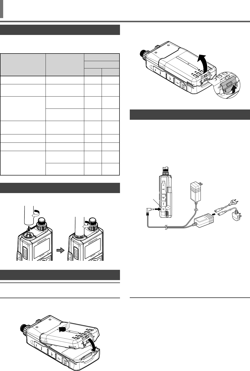
INSTALLING THE BATTERY PACK
Note:
◆Because the battery pack is provided uncharged, you must
charge the battery pack before using it with the transceiver.
Match the guides of the battery pack with the corresponding
grooves on the upper rear of the transceiver, then fi rmly press
the battery case to lock it in place.
To remove the battery pack, lift the release lever to unlock the
battery pack. Lift the battery pack away from the transceiver.
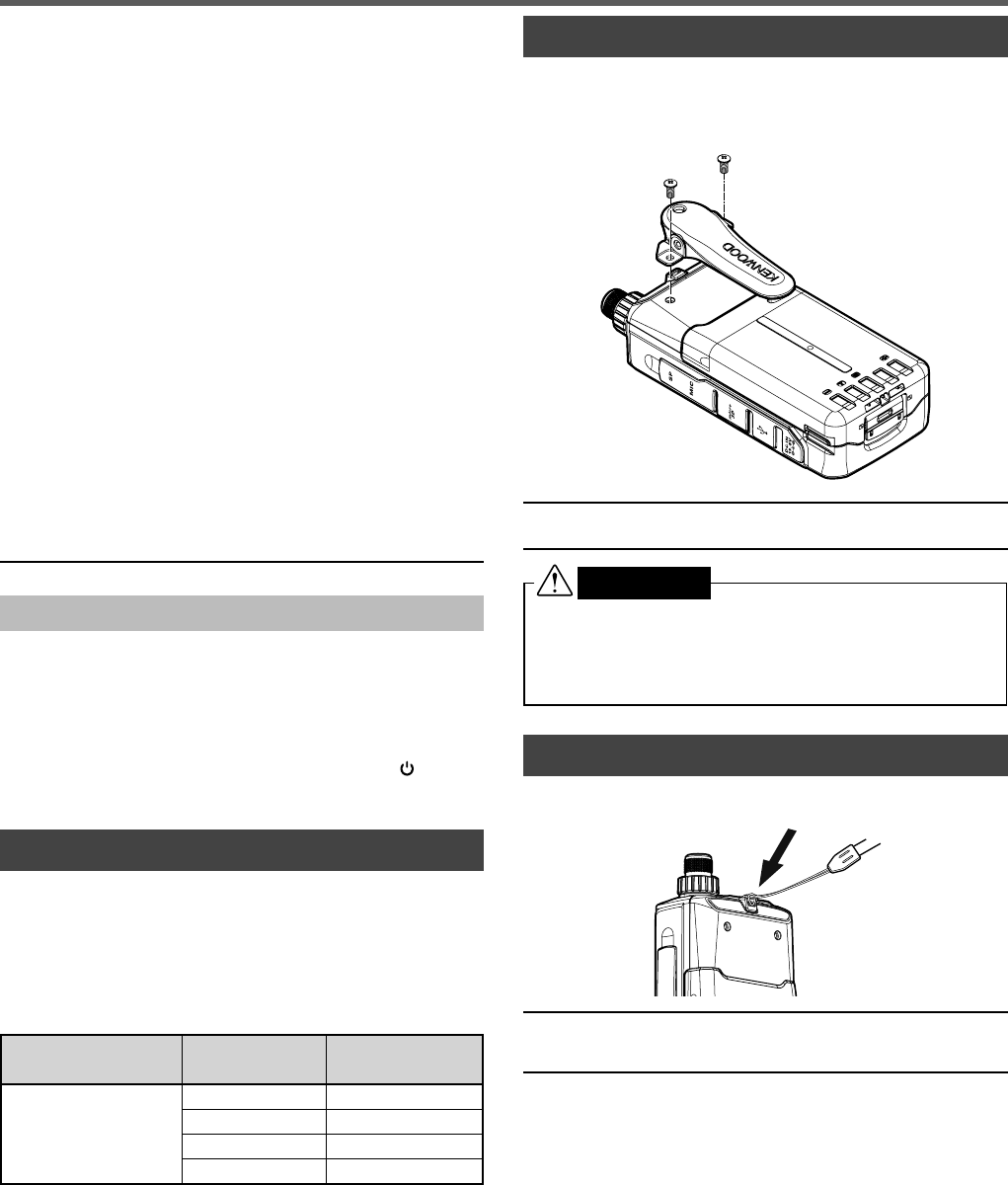
CHARGING THE BATTERY PACK
The battery pack can be charged after it has been installed
onto the transceiver. (The battery pack is provided uncharged
for safety purposes.)
1 Confi rm that the transceiver power is OFF.
• While charging the battery pack, leave the transceiver
power OFF.
2 Insert the charger plug into the DC-IN jack of the
transceiver.
DC IN jack
TH-D74A
TH-D74E
3 Plug the charger into an AC wall outlet.
• Charging starts and "Charging" appears on the display.
• "Charging" disappears when charging is completed.
• The backlight is ON when pressing any key while
charging.
• "Charging" does not appear when charging with the
optional KSC-25LS.
4 It takes approximately 3.5 hours to charge an empty
KNB-75L Li-ion battery pack. After 3.5 hours, remove the
charger plug from the transceiver DC-IN jack.
5 Unplug the charger from the AC wall outlet.
Note:
◆Never leave the battery pack in direct sunlight.
◆The transceiver becomes warm while charging the battery pack.
◆While the battery pack is charged, the ambient temperature
must be within 0°C ~ 40°C (32°F ~ 104°F). Otherwise, charging
does not start. If the transceiver senses that the temperature is
more than 60°C (140° F) during charging, the transceiver stops
charging.
◆Before recharging the battery pack, use the battery pack until the
transceiver stops receiving.
◆Do not plug the charger into the DC-IN jack for more than 24 hours.
◆Do not expose the charger to dripping or splashing conditions.
No objects fi lled with liquids, such as vases, shall be placed on
the AC adapter or charger.
◆Do not place the charger into the liquids.
◆Unplug the charger as soon as possible after the charging period
is over.
◆The charger plug for an AC wall outlet should be used to
disconnect an AC adapter from an AC outlet, and the charger plug
must remain readily operable.
PREPARATION
7
◆After the battery pack is charged, do not unplug and plug the
charger into the AC outlet again. Unpluging the charger will reset
the charging timer and the battery pack will be charged again.
This could result in over-charging.
◆When the battery is installed on the transceiver and you are
using an optional rapid battery charger, do not charge the battery
from the DC-IN jack. Charging the battery from the DC-IN jack
may result in overcharging the battery which can result in the
shortening of the battery life cycle.
◆If the battery pack is not used for a long time, the battery pack
capacity temporarily decreases. In this case, charge the battery
and use the battery pack until the transceiver stops receiving.
Repeat this procedure several times. The battery pack should
recover its capacity.
◆If the charger is plugged into the DC-IN jack before the battery
pack is attached, turn the transceiver power ON and then OFF
again to initiate charging.
◆Exceeding the specifi ed charge period shortens the useful life of
the KNB-75L battery pack.
◆The provided charger is designed to charge only the KNB-75L
battery pack. Charging other models of battery packs may
damage the charger and battery pack.
◆Do not transmit while charging.
◆When not in use, store the battery pack in a cool and dry place.
◆Before charging the battery pack, ensure that the release lever is
fi rmly closed.
◆Attention should be drawn to the environmental aspects of battery
disposal.
◆It takes approximately 3 hours to charge the KNB-75L with the
optional KSC-25LS.
Charger Error
• While charging, if a problem is detected in the battery,
“Charge Error !!” appears on the display.
• The following conditions create charging errors:
• A short in the battery is detected.
• Overvoltage in the battery is detected.
• When a charge error occurs, no key other than [] will
function.
BATTERY LIFE
Before you operate the transceiver outside using a battery
pack, it is important to know how long the battery pack
will last. The operating times listed in the table below are
measured under the following cyclic conditions:
TX: 6 seconds, RX: 6 seconds, Stand-by: 48 seconds
We recommend you carry extra battery packs with you, in
case the battery pack becomes depleted.
Battery Type Output Power Operating Time/
Hours (Approx.)
KNB-75L
Li-ion battery pack
H6
M8
L12
EL 15
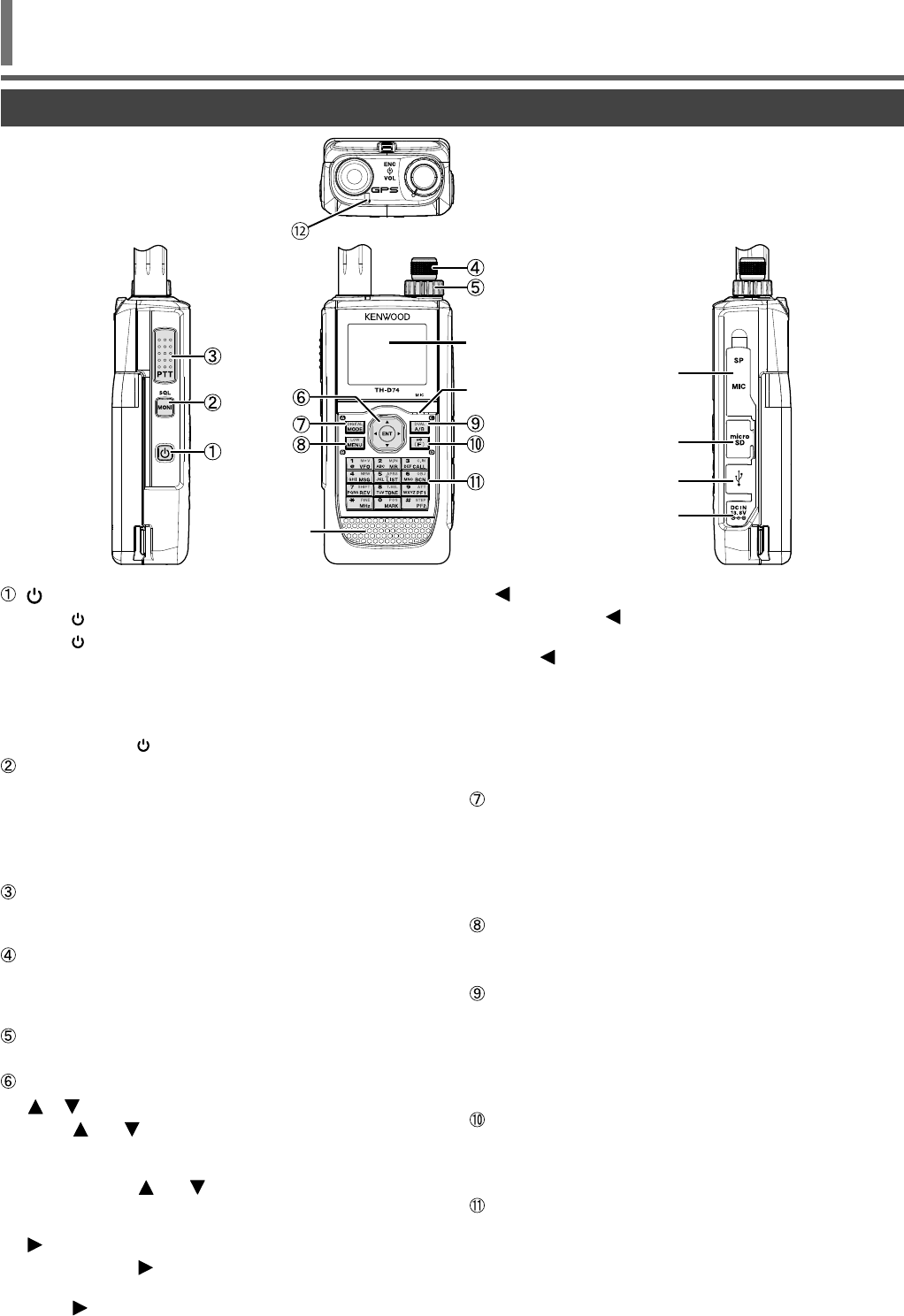
INSTALLING THE BELT CLIP
If desired, you can install the supplied belt clip to the
transceiver.
Attach the belt clip fi rmly using the two supplied M3 x 6 mm
binding screws.
Note:
◆Be careful not to pinch your fi ngers into the belt clip.
CAUTION
• Do not use glue which is designed to prevent screw
loosening when installing the belt clip, as it may cause
damage to the transceiver. Acrylic ester, which is
contained in these glues, may crack the transceiver’s
back panel.
INSTALLING THE HAND STRAP
If desired, you can install the commercially available strap
with suffi cient strength using the holes of the transceiver.
Note:
◆If the strap is thick and does not pass through the holes, install the
strap using the holes of the supplied belt clip.
PREPARATION
8
[ ]
Press [] (1s) to turn the transceiver power ON and OFF.
Press [] to turn the backlight ON and OFF when the
transceiver power is ON.
The backlight turns OFF when the backlight timer elapses.
When the voice guidance function is not set to OFF, the
voice announces the operating states of the transceiver.
When pressing [] while announcing, the voice stops.
[MONI]
Press and hold [MONI] to unmute the speaker in order to
monitor signals.
Release [MONI] to return to normal operation.
Press [F], [MONI] to enter the Squelch level adjustment
mode.
[PTT]
Press and hold [PTT], then speak into the microphone to
transmit.
[ENC] Control
Rotate the [ENC] control to select an operating frequency,
Memory channel, Menu item, setting value and change the
scan direction, etc.
[VOL] Control
Rotate the [VOL] control to adjust the speaker volume.
Multi-Scroll Key
[ ], [ ]
Press [] or [ ] to select an operating frequency,
Memory channel, Menu item, setting value or to change
the scan direction, etc.
Press and hold [ ] or [ ] to change an operating
frequency, Memory channel, Menu item, setting value, etc.
continuously.
[]
Press and hold [] to select a frequency band in VFO
mode.
Press [] to move to the next step in various setting
modes.
[]
Press and hold [] to select a frequency band in VFO
mode.
Press [] to move back to the previous step in various
setting modes.
[ENT]
Press [ENT] to enter frequency direct entry mode in VFO
mode.
Press [ENT] to complete the setting value and move to the
next step in Menu mode or various setting modes.
[MODE]
Press [MODE] to select the mode.
Press [F], [MODE] in DV mode or DR mode to enter
Digital Function Menu mode.
This key operates the function displayed in the lower left
side. (Refer to page 15.)
[MENU]
Press [MENU] to enter Menu mode.
Press [F], [MENU] to cycle the transmit output power.
[A/B]
Press [A/B] to select operation band A or B.
Press [F], [A/B] to switch the Single band mode and Dual
band mode.
This key operates the function displayed in the lower right
side. (Refer to page 15.)
[F]
Press [F] to enter Function select mode.
Press [F] (1s) to turn the transceiver Key lock function ON
and OFF.
12 Keypad
[VFO/1]
Press [VFO] to enter VFO mode. In Memory channel
or CALL channel, press [F], [VFO] to copy the current
Memory channel or Call channel to the VFO (memory
shift).
GETTING ACQUAINTED
KEY AND CONTROL KNOB OPERATIONS
Speaker
Microphone
LCD Display
SP/MIC Jacks
microSD memory
card slot
Micro-USB Connector
(USB2.0, Type B)
DC IN (External power supply)
Jack

9
[MR/2]
Press [MR] to enter Memory Channel mode.
Press [F], [MR] to move to the Memory channel store
screen.
[CALL/3]
Press [CALL] to select the Call channel.
Press [F], [CALL] to store the current operating frequency
to the Call channel.
[MSG] (4)
Press [MSG] to display the APRS Message list.
Press [F], [MSG] to enter the New Message input mode.
[LIST] (5)
Press [LIST] to display the APRS Station list.
• Each time you press [F], [LIST], the mode cycles
through the following: APRS mode ON ➡ KISS mode
ON ➡ OFF.
[BCN] (6)
Press [BCN] to transmit the beacon when APRS mode is
ON.
Press [F], [BCN] to transmit the Object.
[REV] (7)
Press [REV] to turn the Reverse function ON or OFF.
Press [F], [REV] to select the Sift direction.
[TONE] (8)
Press [TONE] to turn the Tone function ON.
• Each time you press [TONE], the function cycles
through the following: Tone ON ➡ CTCSS ON ➡ DCS
ON ➡ Cross Tone ON ➡ OFF.
Press [F], [TONE] to enter the Tone frequency, CTCSS
frequency, DCS code, or Cross Tone setup mode.
Press [F], [TONE] (1s) to start the Tone frequency,
CTCSS frequency, or DCS code scan.
[PF1] (9)
Press [PF1] to activate its programmed function.
Press [F], [PF1] to turn the Attenuator function ON or OFF.
[MARK] (0)
Press [MARK] to display the Position memory list.
Press [MARK] (1s) to enter the Mark Way point
registration mode.
Press [F], [MARK] display your “My position”.
[MHz] ( )
Press [MHz] to enter the MHz mode.
Press [MHz] (1s) to start the MHz scan.
Press [F], [MHz] to enter Fine tuning function mode.
[PF2] (#)
Press [PF2] to activate its programmed function.
Press [F], [PF2] to enter Frequency step setup mode or
Fine step frequency setup mode.
ON AIR/ Busy Indicator
The indicator lights red in transmitting, and lights green in
receiving.
GETTING ACQUAINTED
10
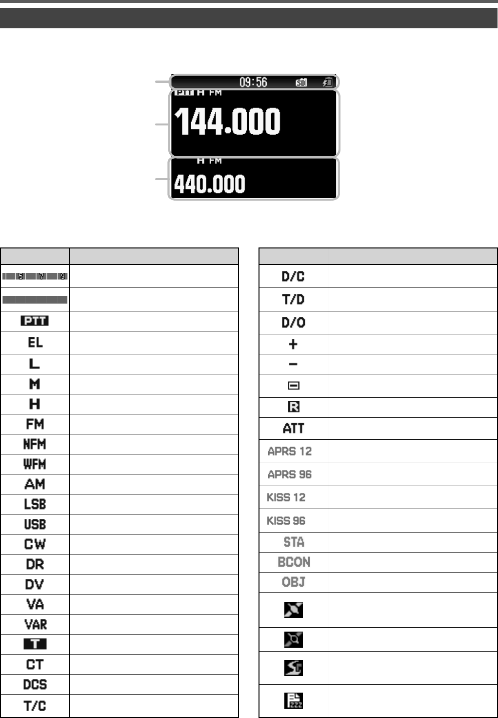
Various function indicator
Indicator Description
Performs as the S meter when receiving a
signal.
Displays the selected power level while
transmitting.
Indicates the transmission band.
Appears while using Economic low output
power.
Appears while using Low output power.
Appears while using Medium output power.
Appears while using High output power.
Appears while in FM mode.
Appears while in Narrow FM mode.
Appears while in Wide FM mode.
Appears while in AM mode.
Appears while in LSB mode.
Appears while in USB mode.
Appears while in CW mode.
Appears while in Digital Repeater mode.
Appears while in Digital Voice mode.
Appears when Voice Alert is set to "VA".
Appears when Voice Alert is set to "VAR".
Appears when the Tone function is ON.
Appears when the CTCSS function is ON.
Appears when the DCS function is ON.
Appears when the Cross tone function is
"TONE/CTCSS".
DISPLAY
GETTING ACQUAINTED
Indicator Description
Appears when the Cross tone function is "DCS/
CTCSS".
Appears when the Cross tone function is
"TONE/DCS."
Appears when the Cross tone function is "DCS/
OFF".
Appears when the Shift function is set to plus.
Appears when the Shift function is set to minus.
Appears when the Shift function is set to -7.6
MHz. (TH-D74E only)
Appears when the Reverse function is ON.
Appears when the Attenuator function is ON.
Appears when the packet communication
speed in APRS mode is set to 1200 bps.
Appears when the packet communication
speed in APRS mode is set to 9600 bps.
Appears when the packet communication
speed in KISS mode is set to 1200 bps.
Appears when the packet communication
speed in KISS mode is set to 9600 bps.
Appears while in Stand-by (Packet mode).
Appears when the Beacon function is ON.
Appears when the Object function is ON.
Appears when the built-in GPS function is ON.
Blinks when the built-in GPS function is
positioning.
Appears when the built-in GPS function is in
Save mode.
Appears when the GPS Track Log function is
ON. Blinks when the built-in GPS function is
positioning.
Appears when the GPS Track Log function is
ON and the built-in GPS function is in Save
mode.
Common icon Display Area
A Band Display Area
B Band Display Area
Frequency Display
11
Indicator Description
Appears when a message is received.
Appears when recording communication.
Appears when playback of a voice message is
paused.
Appears when the Priority Scan function is ON.
Appears when FM radio mode is ON.
The Bluetooth® function is ON.
Connected to a Bluetooth® device.
Appears when a microSD memory card is
recognized. Blinks when a microSD memory
card is mounting or unmounting.
Appears when Weather Alert is ON.
Blinks when Weather Alert is detected.
(TH-D74A only.)
Appears when the key lock is ON.
Indicates the battery level.
Appears during charging of the battery.
Indicates the memory group number.
Indicates the Weather Channel. (TH-D74A
only.)
Appears when the Memory Channel Lockout
function is ON.
Appears when the Repeater Lockout function
is ON.
Appears when Callsign squelch is ON.
GETTING ACQUAINTED
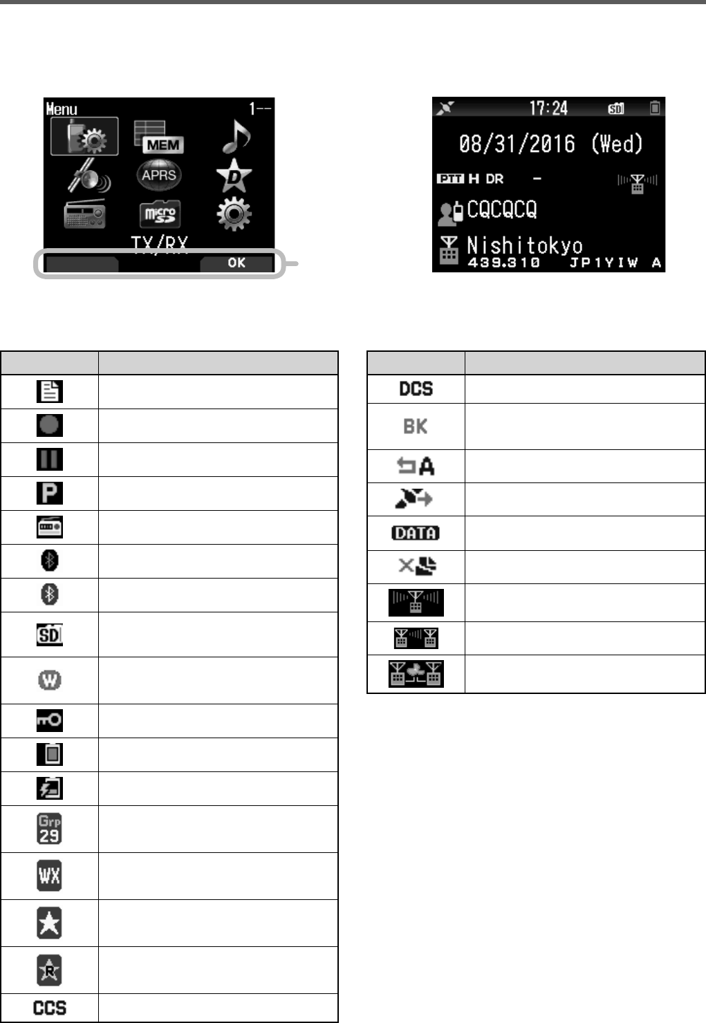
KEY GUIDE Display Area
Menu Mode Display D-STAR (DV/DR mode) Display
Indicator Description
Appears when Code squelch is ON.
TX: Appears in interrupt communication.
RX: Blinks while receiving interrupt
communication.
Appears when the auto reply function is ON.
Appears in GPS transmission.
Appears while in data communication mode.
Blinks while receiving fast data.
Appears when a packet loss happens.
Indicates a repeater for local area call.
Indicates a repeater for call within zone.
Indicates a repeater for gateway call.
12
SWITCHING THE POWER ON/ OFF
Switching the Power ON
Press [ ] (1s).
The power on message momentarily appears, and frequency
screen appears.
Switching the Power OFF
Press [ ] (1s).
ADJUSTING THE INTERNAL CLOCK
When the built-in GPS function is turned ON, the year, month,
day, and time are automatically set from the GPS satellite
information. The default setting of the built-in GPS function
is [On]. If the GPS information cannot be received, you can
manually enter the date and time.
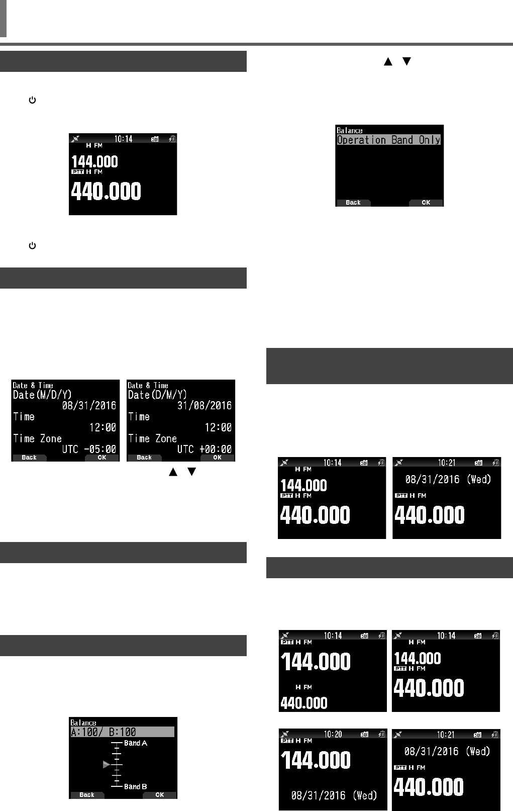
1 Access Menu No. 950.
Date & Time screen appears by pressing [MENU], [PF1],
[LIST], [MARK].
2 Set the date, time, and time zone with [ ]/[ ] or [ENC]
control.
3 Press [A/B].
The date, time, and time zone are set.
4 Press [MENU] to return to the frequency screen.
ADJUSTING THE VOLUME
Rotate the [VOL] control to increase the volume and
counterclockwise to decrease the volume.
When no sound is heard (the squelch is closed), you can
adjust the noise level by rotating the [VOL] control while
pressing the [MONI].
VOLUME BALANCE (BAND A/B)
This function adjusts the volume balance when using the
transceiver with dual bands.
1 Access Menu No. 910.
Volume balance screen appears by pressing [MENU],
[PF1], [VFO], [MARK].
2 Change the balance with [ ]/[ ] or [ENC] control.
• Band A and B are set to the same volume level (MAX)
as a default setting. Pressing [MODE] returns to the
previous screen without changing the setting.
When you select [Operation Band Only], the sound of the
operation band is outputted with priority.
Setting examples
When used in combination with APRS:
When using band A for voice calls, use the transceiver with
the sound of band B set to a low volume level or muted.
When simultaneously scanning two waves:
If [Operation Band Only] is set, a voice is output only for the
operation band when the operation and non-operation band
become busy at the same time.
3 Press [ENT] to set the volume balance.
4 Press [MENU] to return to the frequency screen.
SELECTING DUAL BAND MODE/ SINGLE BAND
MODE
You can switch the transceiver between dual band operation
and single band operation.
1 Press [F], [A/B].
• Each time you press [F], [A/B], the transceiver switches
between Single band and Dual band mode.
Dual Band mode Single Band mode
SELECTING AN OPERATION BAND
You can select a band A or B as an operation band for
changing the frequency or setting various operations, etc.
1 Press [A/B] to select operating band A or B.
Dual Band A Dual Band B
Single Band A Single Band B
BASIC OPERATIONS
13
SELECTING A FREQUENCY BAND
You can change the frequency bands for bands A and B.
1 Press
[ ]/[ ] (1s).
• Each time you press [ ]/[ ] (1s), you cycle to the next
frequency band.
Band A: 144 ➡ 220 ➡ 430 ➡ 144 (MHz).
Band B: 430 ➡ LF/MF(AMBC) ➡ HF ➡ 50 ➡ FMBC
➡ 118 ➡ 144 ➡ VHF(174-216) ➡ 200/300
➡ 430 ➡ VHF(470-524) (MHz).
Note:
◆220 MHz band in Band A is used by the TH-D74A only.
Frequency ranges:
• 118 MHz: Band B 108 ~ 136 MHz
• 144 MHz: 136 ~ 174 MHz
• 220 MHz: 216 ~ 260 MHz (TH-D74A only)
• 200/300 MHz: Band B 216 ~ 410 MHz
• 430 MHz: 410 ~ 470 MHz
• LF/MF(AMBC): 0.1 ~ 1.71 MHz
• HF: 1.71 ~ 29.7 MHz
• 50: 29.7 ~ 76 MHz
• FMBC: 76 ~ 108 MHz
SELECTING THE DEMODULATION MODE
You can select the demodulation mode.
Selecting the Demodulation Mode
1 Press [A/B] to select an operation band.
2 Press [MODE] to select a demodulation mode.
• Each press changes the demodulation mode as follows.
Band A: FM/NFM ➡ DR (DV) ➡ (Returns to FM/NFM)
Band B: FM/NFM ➡ DR (DV) ➡ AM ➡ LSB ➡ USB ➡ CW
➡ (Returns to FM/NFM)
Note:
◆Switching between the DV and DR modes is not possible with the
[MODE] button. (Refer to "Digital Function Menu".)
◆The DV and DR mode cannot be selected for both band A and B
at the same time.
◆Switching between the FM and NFM modes is not possible with
the [MODE] button. (Refer to page 16.)
SELECTING A FREQUENCY
There are 3 operating modes available to choose from: VFO
mode, Memory Channel mode, and Call Channel mode.
VFO Mode
VFO mode allows you to manually change the operating
frequency.
1 Press [VFO] to enter VFO mode.
2 Rotate the [ENC] control to select your desired operating
frequency.
• You can also select a frequency by using the []/[ ]
keys.
• The default step frequency for the [ENC] control varies
according to the model and operating frequency band:
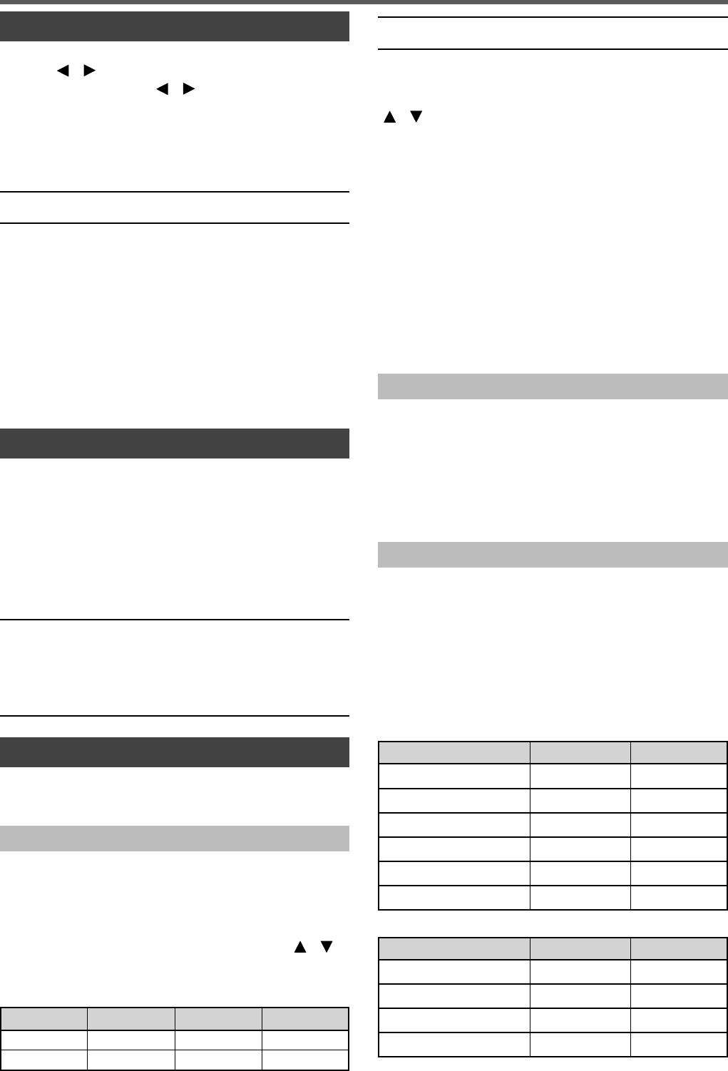
Model 144 MHz 220 MHz 430 MHz
TH-D74A 5 kHz 20 kHz 25 kHz
TH-D74E 12.5 kHz - 25 kHz
Note:
◆220 MHz band is used by the TH-D74A only.
MHz Step
To adjust the frequency by a larger amount, press [MHz] to
enter MHz mode, then rotate the [ENC] control or use the
[]/[ ] keys to adjust the frequency in steps of 1 MHz.
Press [MHz] again to exit MHz mode and adjust the
frequency using the normal step frequency.
Frequency Direct Entry
If the desired operating frequency is far from the current
frequency, using the keypad is the quickest way to change
the frequency.
1 Press [ENT].
The Direct Frequency Entry display appears.
2 Press the numeric keys ([0] ~ [9]) to enter your desired
frequency.
3 To set the entered frequency, press 6 digit.
• Pressing [ENT] before entering all of the digits will set
the remaining digits to 0.
Memory Channel Mode
Memory Channel mode allows you to quickly select a
frequently used frequency and related data which you have
stored in the memory channel.
1 Press [MR] to enter Memory Channel mode.
The Memory channel number appears on the display.
2 Rotate the [ENC] control to select your desired Memory
channel.
Call Channel Mode
Call Channel mode allows you to quickly select a preset
channel to allow immediate calls on that frequency. The Call
channel can be conveniently used as an emergency channel
within your group.
1 Press [CALL] to enter Call Channel mode.
“C” appears on the display.
2 Press [CALL] again, and the transceiver will return to the
previous frequency.
• The default settings are as follows.
TH-D74A
Band (Mode) Call Channel Memory Name
VHF (except DV/DR mode) 146.520 MHz (FM) Call VHF (FM)
VHF(DV/DR mode) 144.000 MHz (DV) Call VHF (DV)
220 MHz(except DV/DR mode) 223.500 MHz (FM) Call 220M (FM)
220 MHz(DV/DR mode) 223.000 MHz (DV) Call 220M (DV)
UHF(except DV/DR mode) 446.000 MHz (FM) Call UHF (FM)
UHF(DV/DR mode) 440.000 MHz (DV) Call UHF (DV)
TH-D74E
Band Call Channel Memory Name
VHF (except DV/DR mode) 145.500 MHz (FM) Call VHF (FM)
VHF(DV/DR mode) 144.8125MHz (DV) Call VHF (DV)
UHF(except DV/DR mode) 433.500 MHz (FM) Call UHF (FM)
UHF(DV/DR mode) 433.6125MHz (DV) Call UHF (DV)
BASIC OPERATIONS
14
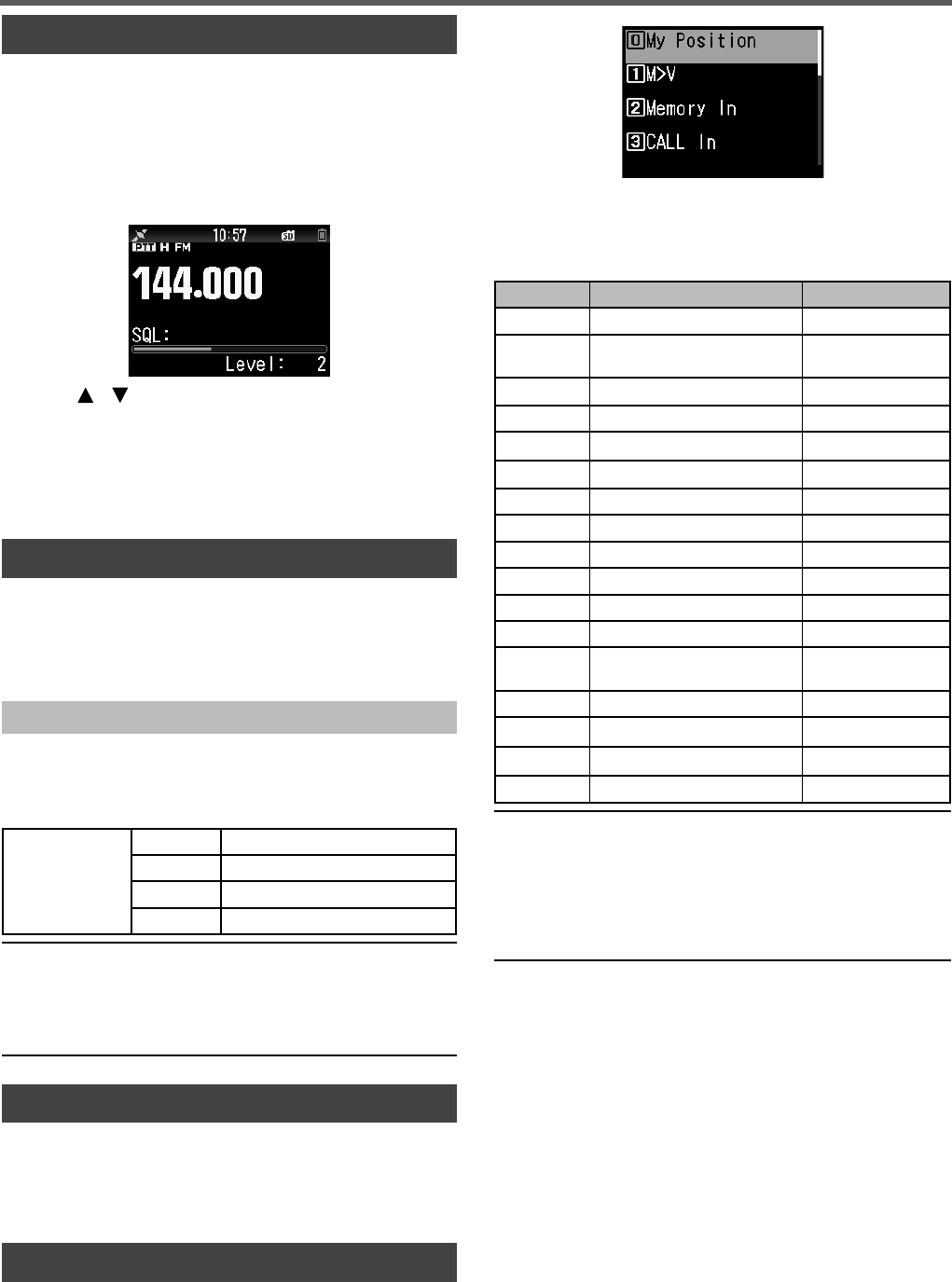
ADJUSTING THE SQUELCH
Squelch is used to mute the speaker when no signals are
present. With the squelch level set correctly, you will hear
sound only while actually receiving a signal. The higher the
squelch level selected, the stronger the signals must be in
order to hear them. You can set the squelch level separately
for Bands A and B.
1 Press [F], [MONI].
The squelch level appears on the display.
2 Press [ ]/[ ] or rotate the [ENC] control of your
selected band, when no signals are present, and select
the squelch level at which the background noise is just
eliminated.
3 Press [ENT].
The squelch level is set.
TRANSMITTING
1 Select your desired band and frequency/channel.
2 Press and hold [PTT], and speak into the microphone to
transmit.
3 When you fi nish speaking, release the [PTT] switch.
Selecting an Output Power
Selecting a lower transmit power is the best way to reduce
battery consumption, if communication is still reliable.
Press [F], [MENU] to select high (H), medium (M), low (L), or
economic low (EL) power.
Battery Pack
KNB-75L
H Approx. 5 W
M Approx. 2 W
L Approx. 0.5 W
EL Approx. 0.05 W
Note:
◆You can program different power settings for bands A and B.
◆You can not change the output power in transmitting.
◆You can not set the output power in each frequency band.
◆Refer to the details instruction manual (User Manual) when using
with an external power supply or Alkaline batteries.
MONITOR
When you are receiving while the squelch function is ON,
weak signals may become intermittent.
1 Press and hold [MONI].
• The speaker is unmuted and you can monitor the signals.
FUNCTION SELECT MODE
Press [F] to enter Function Select mode. Press [F] again to
return to the previous screen.
Pressing each key in the Function Select Mode performs the
operation of the second function assigned to each key.
The function of each key may differ depending on the mode
when [F] is pressed (refer to the following table).
Key Second function Remarks
[MARK] (0) My position Built-in GPS is On.
[VFO] (1) Memory shift Only in Memory
mode or Call mode
[MR] (2) Memory channel registration
[CALL] (3) Call channel registration
[MSG] (4) APRS message creation
[LIST] (5) APRS/ KISS mode switching
[BCN] (6) Object packet Only in APRS mode
[REV] (7) Shift
[TONE] (8) Tone frequency
[PF1] (9) Attenuator
[MHz] (*) Fine mode
[PF2] (#) Frequency Step
[MODE] Digital function menu Only in DV/DR
mode
[MENU] Transmission power
[A/B] Dual or Single band switching
[F] Function select mode end
[MONI] Squelch setting
Note:
◆The tone frequency changes to the following setting items
depending on the conditions of this transceiver.
Tone OFF: Invalid
Tone ON: Tone frequency
CTCSS ON: CTCSS frequency
DCS ON: DCS frequency
Cross Tone ON: Cross tone combination
BASIC OPERATIONS
15
SOFTWARE KEY OPERATION
Software keys ([Back], [OK], etc.) are displayed in the key
guide area of various setting screens and other screens.
To select or operate the displayed functions, press the
corresponding keys.
Example:
[Back] ➡ Press [MODE]: Returns to the previous screen
without confi rming the displayed setting.
[OK] ➡ Press [A/B]: Changes to the next screen.
CHARACTER ENTRY
In the screens that require you to enter text such as the
screen for entering a memory name or power-on message,
there are two methods to enter text. One is to enter text using
the number keys in the same ways as a mobile phone and
the other is to enter text by selecting characters one by one
with the Multi-Scroll Key or [ENC] control.
Keypad Character Entry
1 Enter text with [0] to [9] and [ENT].
• The each press of a key changes the character that can
be entered.
• To enter another character assigned to the same key,
move the cursor to the next position with [] ([ ]
moves the cursor to the previous position) and enter the
next character.
• Pressing [A/B] deletes a character. The character at the
cursor position is deleted. The backspace operation is
performed when there is a blank space.
• Pressing []/[ ] moves the cursor.
Example: Entering the power-on message (Menu No.903)
• Pressing [MODE] changes the character input mode.
• Pressing [A/B] clears the text.
2 Press [].
The cursor moves to the right. If 16 characters are
entered, this operation confi rms the characters and ends
text input.
3 Press [ENT].
The text is confi rmed and text input ends.
MENU MODE
Many functions on this transceiver are selected or confi gured
through the Menu instead of physical controls.
MENU ACCESS
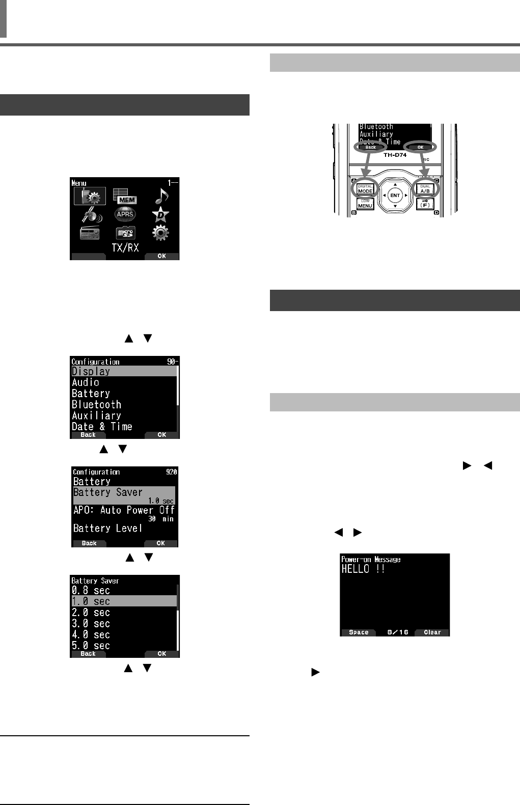
Example: Setting the time for [Battery Saver] of Menu No. 920.
1 Press [MENU].
The transceiver enters the enu mode. The icon currently
selected by the cursor is highlighted, and the item name is
displayed at the bottom of the screen. (Example: TX/RX)
Directly Entering a Menu Number (Direct Access)
You can also directly enter a Menu number using the number
keys from this screen.
Press [PF1], [MR], [MARK] for Menu No.920. In this case,
you can move to step 4.
2 Select [Confi guration] with []/[ ] or [ENC] control and
press [A/B].
3 Select [Battery] with [ ]/[ ] or [ENC] control and press
[A/B].
4 Select [Battery Saver] with [ ]/[ ] or [ENC] control and
press [A/B].
5 Select a setting value with [ ]/[ ] or [ENC] control and
press [A/B] to set the value.
6 Press [MENU].
The Menu mode ends and the frequency screen appears.
For subsequent Menu operations, steps 1 to 4 will be
referred to as "Access Menu No. XXX".
Note:
◆Pressing [PTT] during each operation ends Menu mode without
confi rming the setting.
◆Pressing [MODE] during each operation returns to the previous
screen. Also, pressing [MODE] during step 4 discards the new
setting value and returns to the previous operation.
◆Pressing [MENU] in scanning cancels scan.

16
Entering Text with the Multi Scroll Key or [ENC]
1 Display the character with [ ]/[ ] or [ENC] control.
2 Press [].
The character or symbol is entered and the cursor moves
to the right.
Pressing [A/B] deletes the character selected by the
cursor. If it is pressed when there is no character selected
by the cursor, the cursor moves to the left.
MENU MODE
Auto Cursor Shift
This function provides assistance for entering text using
the number keys. It is convenient to use this function when
consecutively entering characters with the same key because
it automatically moves the cursor to the right after a set time
has passed.
You can set this time until the cursor is moved to the desired
time.
1 Access Menu No. 945.
Select [Off], [1.0], [1.5], or [2.0] (sec.).
2 Press [ENT].
MENU CONFIGURATION
No. Display Description Setting Values
TX/RX - RX
100 Programmable VFO Programmable VFO setting Varies with the selected frequency band
101 Beat Shift Beat shift Type 1 - Type 8
102 Detect Out Select Detect output select Off (AF)/ IF(Single Band)/ Detect(Single Band)
103 FM Narrow FM narrow Off/ On
104 MW/ SW Antenna MW/ SW Antenna ATT connector / Bar Antenna
105 WX Alert Weather alert Off/ On (TH-D74A only)
TX/RX - TX
110 TX Inhibit TX inhibit Off/ On
111 Time-out Timer Time-out timer 0.5/ 1.0/ 1.5/ 2.0/ 2.5/ 3.0/ 3.5/ 4.0/ 4.5/ 5.0/ 10.0 [min]
112 Mic. Sensitivity Microphone sensitivity Low/ Medium/ High
TX/RX - RX Filter
120 SSB High Cut SSB high cut frequency 2.2/ 2.4/ 2.6/ 2.8/ 3.0 [kHz]
121 CW Width CW bandwidth 0.3/ 0.5/ 1.0/ 1.5/ 2.0 [kHz]
122 AM High Cut AM high cut frequency 3.0/ 4.5/ 6.0/ 7.5 [kHz]
TX/RX - Scan
130 Resume Resume method Time/ Carrier/ Seek
131 Resume (Digital) Resume method (Digital) Time/ Carrier/ Seek
132 Time Restart Time operate restart time 1 - 5 - 10 [sec]
133 Carrier Restart Carrier operate restart time 1 - 2 - 10 [sec]
134 Priority Scan Priority scan Off/ On
135 Scan Auto Backlight Scan auto backlight Off/ On
136 Auto Weather Scan Auto Weather Channel Scan Off/ On (TH-D74A only)
TX/RX - Repeater
140 Offset Frequency Offset frequency Varies with the selected frequency band
141 Auto Offset Auto repeater offset Off/ On
142 CALL Key CALL key function CALL (TH-D74A)/ 1750Hz (TH-D74E)
143 1750Hz TX Hold 1750 Hz TX hold Off/ On
TX/RX - VOX
150 VOX VOX on/ off Off/ On
151 Gain VOX gain level 0 - 4 - 9
152 Delay VOX delay time 250/ 500/ 750/ 1000/ 1500/ 2000/ 3000 [ms]
153 TX on Busy VOX on busy Off/ On
TX/RX - DTMF
160 Encode Speed Encode speed 50/ 100/ 150 [ms]
161 Pause Time Pause time 100/ 250/ 500/ 750/ 1000/ 1500/ 2000 [ms]
162 TX Hold TX hold Off/ On
163 DTMF Memory DTMF memory Up to 10 channels for DTMF memory channel
Up to 16 characters for DTMF memory name
Up to 16 digits for DTMF memory code
164 EchoLink Memory EchoLink memory Up to 10 channels for EchoLink memory channel
Up to 8 characters for EchoLink memory name
Up to 8 digits for one channel code
TX/RX - CW
170 Pitch Frequency Pitch frequency 400 - 800 - 1000 [Hz]
171 Reverse Reverse Normal/ Reverse

17
No. Display Description Setting Values
TX/RX - Others
180 QSO Log QSO log Off/ On
181 LED Control LED control RX: Check
FM Radio: Uncheck
Memory - Memory Channel
200 View List Memory channel list -
201 Group Name Memory group name input Up to 16 characters
202 Recall Method Memory channel recall method All Bands/ Current Band
203 Group Link Memory group link registration register up to 30 memory group links
204 CALL Ch List CALL channel list -
Memory - Repeater List
210 View List Repeater list -
Memory - Callsign List
220 View List Callsign list -
Audio File - Recording File
300 View List Recording fi le list -
301 Recording Recording Off/ On
302 Recording Band Recording band Band A/ Band B
Audio File - Voice Message
310 View List Voice message list -
311 TX Monitor TX monitor Off / On
312 Digital Auto Reply Digital auto reply Off/ Voice Message 1 - Voice Message 4
GPS - Basic Settings
400 Built-in GPS Built-in GPS Off/ On
401 My Position My position My Position 1 - 5/ GPS
402 Position Ambiguity Position ambiguity mode Off/ 1-Digit - 4-Digit
403 Operating Mode built-in GPS operating mode Normal/ GPS Receiver
404 Battery Saver Battery saver time Off/ 1min/ 2min/ 4min/ 8min/ Auto
405 PC Output GPS data output to PC Off/ On
406 Sentence Sentence $GPGGA/ $GPGLL/ $GPGSA / $GPGSV/ $GPRMC/
$GPVTG
GPS - Track Log
410 Track Log Track log recording Off/ On
411 Clear Track Log Clear track log -
412 Record Method Record method Time/ Distance/ Beacon
413 Interval Interval time 2 - 10 - 1800 [sec]
414 Distance Distance 0.01 - 9.99 [km]
APRS - Basic Settings
500 My Callsign Callsign entry Up to 9 characters
501 Icon Icon Person/ Bicycle/ Motorcycle, etc. (total 68 icons)
502 Position Comment Position comment Off Duty/ Enroute/ In Service/ Returning/ Committed/
Special/ PRIORITY/ CUSTOM0 ~ CUSTOM6/
EMERGENCY!
503 Status Text Status text
Status text: 1 - 5
TX Rate: Off/ 1/1 - 1/4 - 1/8
Up to 42 characters
504 Packet Path Packet path type
Type: New-N PARADIGM/ Relay/ Region/ Others1-
Others3,
WIDE1-1: Off/On, RELAY: Off/On, ABBR: Up to 5
characters,
Total Hops: 0 - 1 - 7, Path: Up to 79 characters
505 Data Speed Data communications speed 1200bps/ 9600bps
506 Data Band Internal data band type A Band/ B Band
507 DCD Sense DCD sense type Busy/ Detect Data/ Off (Ignore)
508 TX Delay TX delay time 100/ 150/ 200/ 300/ 400/ 500/ 750/ 1000 [ms]
509 APRS Lock APRS lock Frequency/ PTT/ APRS Key: All unchecked
APRS - Beacon TX Control
510 Method Method Manual/ PTT/ Auto/ SmartBeaconing
511 Initial Interval Initial Interval timer 0.2/ 0.5/ 1/ 2/ 3/ 5/ 10/ 20/ 30/ 60 [min]
512 Decay Algorithm Decay Algorithm Off/ On
513 Prop. Pathing Prop. Pathing Off/ On
514 Speed Speed Off/ On
515 Altitude Altitude Off/ On
MENU MODE

18
No. Display Description Setting Values
516 Object Object/ Item settings
Name: up to 9 characters, Type: Live Object/ Killed
Object/ Live Item/ Killed Item, Method: Off/ Temp./
Auto(15 min)/ Auto(30 min)/ Auto(60 min), N(S): Latitude,
E(W): Longtitude, Icon (Total 68 kinds): Eyeball/ Portable
(Tent)/ HAM store, etc., Comment: up to 42 characters
APRS - QSY Information
520 QSY Info. in Status QSY information in status Off/ On
521 Tone/Narrow Tone/ Narrow Off/ On
522 Shift/Offset Shift/ Offset Off/ On
523 QSY Limit Distance QSY limit distance Off/ 10/ 20 … 2490/ 2500
APRS - SmartBeaconing
530 Low/High Speed Low speed/ High speed setting Low Speed: 2 - 5 - 30 [km/h]
High Speed: 2 - 70 - 90 [km/h]
531 Slow Rate Low speed transmission interval time 1- 30 - 100 [min]
532 Fast Rate High speed transmission interval time 10 - 120 - 180 [sec]
533 Turn Angle Driving direction change, minimum value
setting 5 deg - 28 deg - 90 deg
534 Turn Slope Driving direction change, additional value
setting 1 10deg/speed - 26 10deg/speed - 255 10deg/speed
535 Turn Time Minimum time delay between each
beacon transmission 5 - 60 - 180 [sec]
APRS - Waypoint
540 Format Way point format NMEA/ MAGELLAN/ KENWOOD
541 Length Way point name length 6-Char/ 7-Char/ 8-Char/ 9-Char
542 Output Way point output type All/ Local/ Filtered
APRS - Packet Filter
550 Position Limit Position limit Off/ 10/ 20 … 2490/ 2500
551 Filter Type Filter type Weather/ Digipeater/ Mobile/ Object/ NAVITRA/ 1-WAY/
Others
APRS - Message
560 User Phrases User phrases Up to 32 characters x 8 phrases
561 Auto Reply Auto message reply Off/ On
562 Reply To Reply to Up to 9 characters
563 Reply Delay Time Reply delay time 0/ 10/ 20/ 30/ 60 [sec]
564 Reply Message Text Reply message text input Up to 50 characters
APRS - Notifi cation
570 RX Beep RX beep Off/ Message Only/ Mine/ All New/ All
571 TX Beep TX beep Off/ On
572 Special Call Special call Up to 9 characters
573 Display Area Display area Entire Always/ Entire Display/ One Line
574 Interrupt Time Interrupt time 3/ 5/ 10/ 20/ 30/ 60/ infi nite [sec]
575 APRS Voice APRS voice Off/ On
APRS - Others
580 PC Output PC output type Off/ Raw Packets/ Waypoints
581 Network Network type APRS[APK004]/ Altnet
582 Voice Alert Voice alert type Off/ VA/ VAR
583 VA Frequency VA frequency type 67.0 - 100.0 - 254.1 Hz
584 Message Group Code Message group code Up to 9 characters x 6 codes (ALL,QST,CQ,KWD)
585 Bulletin Group Code Bulletin group code Up to 5 characters x 6 codes
Digital - RX History
600 View History View History -
Digital - TX/RX
610 My Callsign Callsign entry Up to 8 characters + up to 4 characters
611 TX Message TX message Off/ 1/ 2/ 3/ 4/ 5
612 Direct Reply Direct reply Off/ On
613 Auto Reply Timing Auto reply timing Immediate/ 5/ 10/ 20/ 30/ 60 [sec]
614 Data TX End Timing Data TX end timing Off/ 0.5/ 1/ 1.5/ 2 [sec]
615 EMR Volume Level EMR Volume level 1 - 25 - 50
616 RX AFC RX AFC Off/ On
617 FM Auto Det. on DV FM auto detector on DV Off/ On
618 Data Frame Output Data Frame Output All/ Related to DSQL/ DATA Mode
619 Break Call Break Call Off/ On
MENU MODE

19
No. Display Description Setting Values
Digital - Digital Squelch
620 Select Type Select Type Off/Code Squelch/ Callsign Squelch
621 Digital Code Digital Code 00 - 99
Digital - GPS Data TX
630 GPS Info. in Frame GPS Information in frame Off/ On
631 Sentence Sentence $GPGGA/ $GPGLL/ $GPGSA/ $GPGSV/ $GPRMC/
$GPVTG
632 Auto TX Auto TX Off/ 0.2/ 0.5/ 1/ 2/ 3/ 5/ 10/ 20/ 30/ 60 [min]
Digital - RX Notifi cation
640 Display Method Display method Off/ All/ Related to DQSL/ My Station Only
641 Single Display Size Single display size Half Display/ Entire Display
642 Dual Display Size Dual display size Half Display/ Entire Display
643 Display Hold Time Display hold time 0 / 3/ 5/ 10/ 20/ 30 / 60/ Infi nite [sec]
644 Callsign Announce Callsign announce Off/ Kerchunk/ Except Kerchunk/ My Station Only/ All
645 Standby Beep Standby beep Off/ On
FM Broadcasting - Basic Settings
700 FM Radio Mode FM radio mode Off/ On
701 Auto Mute RET. Time Auto mute return time 1 - 3 - 10 [sec]
FM Broadcasting - Memory
710 FM Radio List FM radio list -
SD Card - Export
800 Confi g Data Confi g data -
801 Confi g Data + V.Msg Confi g data + V.msg -
802 Repeater List Repeater list -
803 Callsign List Callsign list -
SD Card - Import
810 Confi g Data Confi g data -
811 Confi g Data + V.Msg Confi g data + V.msg -
812 Repeater List Repeater list -
813 Callsign List Callsign list -
SD Card - Unmount
820 Execute Unmount execute -
SD Card - Format
830 Execute Format execute -
SD Card - Memory Size
840 View Free capacity -
Confi guration - Display
900 Backlight Control Backlight control Auto/ Auto (DC-IN)/ Manual/ On
901 Backlight Timer Backlight timer 3 - 10 - 60 [sec]
902 LCD Brightness LCD brightness High/ Medium/ Low
903 Power-on Message Power-on message input Up to 16 characters
904 Single Band Display Single band display type Off/ GPS(Altitude) / GPS(GS)/ Date
905 Meter Type Meter type Type 1/ Type 2/ Type 3
906 Background Color Background color select Black/ White
Confi guration - Audio
910 Balance Audio balance A:100/ B:0, A:100/ B:25, A:100/ B:50, A:100/ B:75, A:100/
B:100, A:75/ B:100, A:50/ B:100, A:25/ B:100, A:0/B:100,
Operation Band Only
911 TX/RX EQ TX/RX EQ RX EQ/ TX EQ(FM, NFM)/ TX EQ(DV)
912 TX EQ Level TX EQ Level -9 - 0 - +3 [dB]
913 RX EQ Level RX EQ Level -9 - 0 - +9 [dB]
914 Beep Beep Off/ On
915 Beep Volume Beep Volume Level 1 - Level 5 - Level 7
916 Voice Guidance Voice Guidance Off, Manual, Auto1, Auto2
917 Voice Guidance Vol. Voice Guidance Vol. Level 1 - Level 5 - Level 7
918 USB Audio Out. Lvl. USB Audio Output level Level 1 - Level 5 - Level 7
Confi guration - Battery
920 Battery Saver Battery Saver Off/ 0.2/ 0.4/ 0.6/ 0.8/ 1.0/ 2.0/ 3.0/ 4.0/ 5.0 [sec]
921 APO: Auto Power Off APO: Auto Power Off Off/ 15/ 30/ 60 [min]
922 Battery Level Battery Level -
MENU MODE

20
No. Display Description Setting Values
Confi guration - Bluetooth
930 Bluetooth Bluetooth Off / On
931 Connect Connect -
932 Device Search Device Search -
933 Disconnect Disconnect -
934 Pairing Mode Pairing Mode -
935 Device Information Device Information Up to 19 characters
936 Auto Connect Auto Connect Off / On
Confi guration - Auxiliary
940 PF1 Key PF1 Key Recording - Voice Message 1-4 - Voice Guidance - Battery
Level - VOX - Group Name - Balance (PF1) - GPS
(PF2) - Track LOG - SQL - SHIFT - STEP - LOW - Key
Lock - Lockout - M>V - T. SEL - NEW - Voice Alert - LCD
Brightness - DTMF CH0 - EchoLink CH0 - 1750Hz Tone
- M. IN
941 PF2 Key PF2 Key
942 PF1 (Mic) PF1 (Mic) Recording - Voice Message 1-4 - Voice Guidance - Battery
Level - VOX - Group Name - Balance - GPS - Track LOG -
SQL - SHIFT - STEP - LOW - Key Lock - Lockout - M>V -
T. SEL - NEW - Voice Alert - LCD Brightness - DTMF CH0
- EchoLink CH0 - 1750Hz Tone - Screen Capture - MODE
- MENU - A/B (PF1 Mic) - VFO (PF2 Mic) - MR (PF3
Mic) - CALL- MSG - LIST - BCON - REV - TONE - MHz -
MARK - DUAL - APRS - OBJ - ATT - FINE - POS - BAND
- MONI - UP - DOWN
943 PF2 (Mic) PF2 (Mic)
944 PF3 (Mic) PF3 (Mic)
945 Cursor Shift Cursor shift Off/ 1.0/ 1.5/ 2.0 [sec]
946 Secret Access Code Secret access code input 000 - 999 (TH-D74A only)
Confi guration - Date & Time
950 Setting Date and time setting -
Confi guration - Lock
960 Keys Lock Type Keys lock type Key Lock/ Frequency Lock
961 DTMF Keys Lock DTMF keys lock Off/ On
962 Mic Keys Lock Microphone keys lock Off/ On
963 Volume Lock Volume lock Off/ On
Confi guration - Units
970 Speed, Distance Speed/ Distance mi/h, mile (TH-D74A)/ km/h, km (TH-D74E)/ knots, nm
971 Altitude, Rain Altitude/ Rain feet, inch (TH-D74A)/ m, mm (TH-D74E)
972 Temperature Temperature °F (TH-D74A)/ °C (TH-D74E)
973 Latitude, Longitude Latitude/ Longitude dd°mm.mm’/ dd°mm’ss.s”
974 Grid Square Format Grid square format Maindenhead Grid/ SAR Grid (CONV)/ SAR Grid (CELL)
Confi guration - Interface
980 USB Function USB Function COM+AF/IF Output/ Mass Storage
981 PC Output(GPS) PC Output(GPS) USB/ Bluetooth
982 PC Output(APRS) PC Output(APRS) USB/ Bluetooth
983 KISS PC Intput/ Output(KISS) USB/ Bluetooth
984 DV/DR PC Intput/ Output(DV/DR) USB/ Bluetooth
Confi guration - System
990 Language Language English/ Japanese
991 Version Firmware version -
999 Reset Reset VFO Reset/ Partial Reset/ Full Reset
Note:
◆Menu descriptions and setting values are subject to change without prior notice.
◆Bold character in setting values indicates a default setting.
MENU MODE
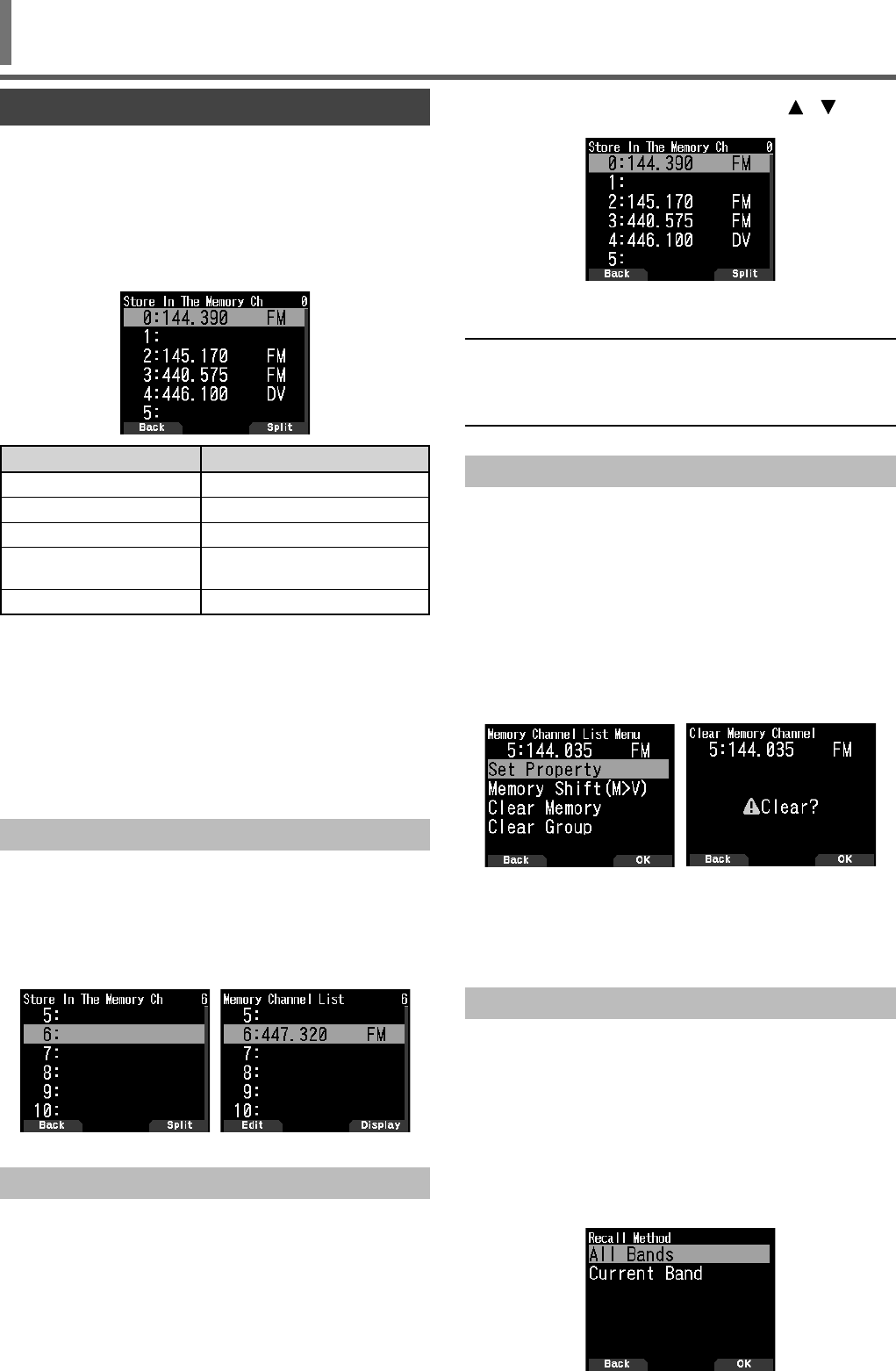
21
MEMORY CHANNEL LIST
The memory channel confi gurations can be displayed on the
Memory Channel List screen. In the Memory Channel List
screen, you can select a channel to store or to recall. You can
assign a name to a Memory Channel.
1 Press [MR] to switch to the memory mode.
2 Press [ENT].
Memory channel list appears. You can also access to the
memory channel list by Menu No. 200.
Display Type
[0] to [999] Memory channels
[L 0], [U 0] to [L49], [U49] Program scan memory
[Pri] Priority scan memory
[A 1] to [A10] Weather channels
(TH-D74A only)
[C] CALL channels
3 Select the channel.
You can select the channel by inputting the channel
number from 0 to 999 by 12 keypad. When you select 1
or 2 digits channel, you can also select by inputting the
channel number and pressing [ENT].
4 Press [ENT].
The selected channel is set and return to the frequency
display.
Storing Simplex And Standard Repeater Frequencies
1 Select the frequency, mode, etc.
2 Press [F], [MR].
The screen for selecting the channel to store appears.
3 Select the memory channel number.
4 Press [ENT].
The simplex channel is registered.
Storing Odd-Split Repeater Frequencies
When you change the RX and TX frequencies, register the
RX frequency fi rst and then register the TX frequency. Only
the TX frequency cannot be registered.
1 Register the RX frequency.
A split channel can be registered only to an already
registered memory channel.
2 Display the TX frequency.
3 Press [F], [MR].
The screen for selecting the channel to store appears.
4 Select the memory channel number using [ ]/[ ] or
[ENC] control.
5 Press [A/B].
The split channel is registered.
Note:
◆You cannot set the TX and RX frequencies on different frequency
bands.
◆You cannot set the different frequency step size for the TX and RX
frequencies.
Clearing A Memory Channel
You can clear the specifi ed channel of the registered memory
channels.
1 Press [MR] to enter the memory mode.
2 Press [ENT].
The memory channel list appears. You can also access to
the memory channel list by Menu No. 200.
3 Select the specifi ed channel and press [MENU].
The memory channel list menu appears.
4 Select [Clear Memory] and press [A/B].
Clear memory channel screen appears. Press [MODE] to
return to the memory channel list menu.
4 Press [A/B].
The specifi ed memory channel is cleared.
To clear another memory channel, repeat the procedure
from step 3.
Memory Recall Method
This menu provides you with the option to recall memory
channels with stored frequencies in your current frequency
band, or all memory channels:
1 Access Menu No. 202.
[All Bands]:
This allows you to recall all programmed memory
channels.
[Current Band]:
This allows you to recall only those memory channels that
have stored frequencies within the current frequency band.
MEMORY CHANNELS
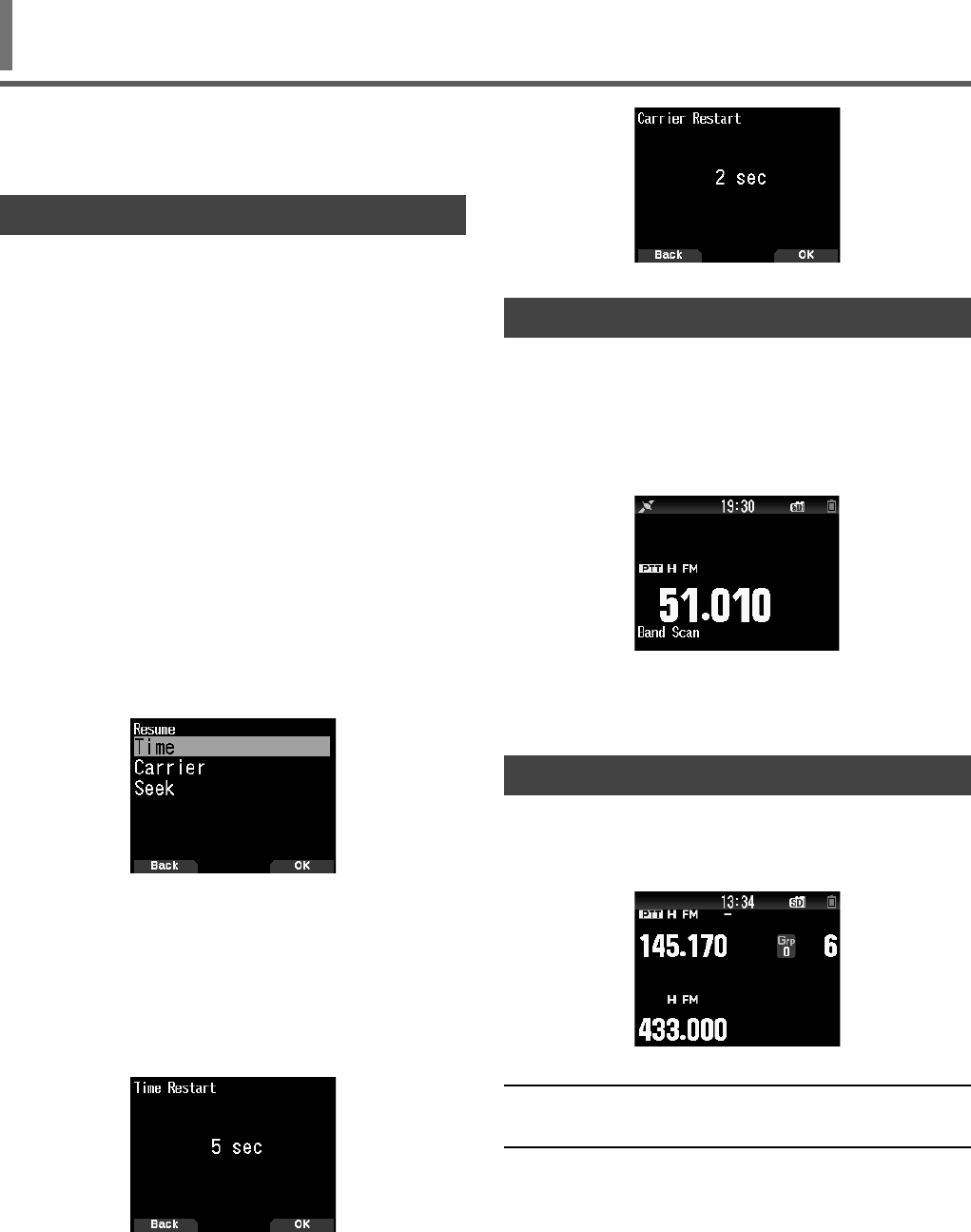
22
Scan is a useful feature for hands-off monitoring of your
favorite frequencies. Becoming comfortable with all types of
Scan will increase your operating effi ciency.
SELECTING A SCAN RESUME METHOD
The transceiver stops scanning at a frequency or Memory
channel on which a signal is detected. It then continues
scanning according to which resume mode you have
selected. You can choose one of the following modes.
Time-Operated mode
The transceiver remains on a busy frequency or Memory
channel for approximately 5 seconds, and then continues to
scan even if the signal is still present.
Carrier-Operated mode
The transceiver remains on a busy frequency or Memory
channel until the signal drops out. There is a 2 second delay
between signal drop-out and scan resumption.
Seek mode
The transceiver remains on a busy frequency or Memory
channel even after the signal drops out and does not
automatically resume scanning.
1 Access Menu 130.
• In digital (DV/DR mode), access Menu No. 131.
2 Set the Scan Resume mode to “Time” (Time-Operated),
“Carrier” (Carrier-Operated) or “Seek” (Seek).
Time-Operate Resume Time
Set the hold time for the Time-Operate scan method.
When a signal is received, scan will pause at that frequency
for the duration of the hold time you set. When the set time
elapses, scan will resume (even if the signal is still being
received).
1 Access Menu No. 132.
2 Set the resume time to 1 ~ 10 sec.
Carrier-Operated Resume Time
Set the hold time for the Carrier-Operate scan method.
When a signal is received, scan will pause at that frequency.
When the signal stops, scan will resume after the duration of
the hold time you set.
1 Access Menu No. 133.
2 Set the resume time to 1 ~ 10 sec.
SCAN
BAND SCAN
Band scan monitors all frequency range that is stored in
Menu No. 100 (Programmable VFO), using the current
frequency step size.
1 Select your desired operation band and frequency.
2 Press [VFO] (1s).
Band scan appears and scan starts at the current
frequency.
• The 1 MHz decimal point blinks while scanning is in
progress.
3 To quit band scan, press [VFO].
MEMORY SCAN
Use memory scan to monitor all Memory channels
programmed with frequency data.
1 Press [MR] (1s).
Scan starts at the current memory channel.
2 To quit memory scan, press [MR].
Note:
◆At least 2 Memory channels must contain data and must not be
locked out of scan.
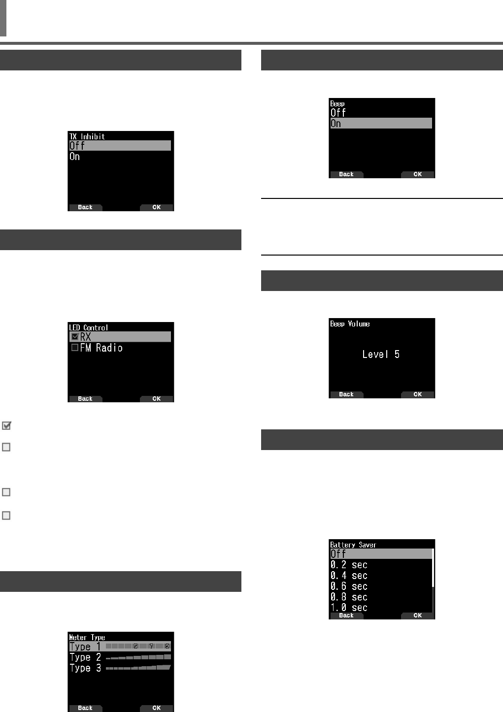
23
KEY BEEP
You can turn the transceiver beep function [On] or [Off].
1 Access Menu No.914.
2 Set the beep function to [On] or [Off].
Note:
◆Even with the beep function turned off, the transceiver will beep
1 minute before the power turns off when Auto Power off is
activated.
◆After transmitting for the maximum time duration according to the
Time-out Timer, the transceiver will beep.
BEEP VOLUME
You can set the beep volume.
1 Access Menu No. 915.
2 Set the value from [Level 1] to [Level 7].
BATTERY SAVER
The Battery Saver extends the operating time of the
transceiver. It automatically activates when the squelch is
closed and no key is pressed for more than 5 seconds. To
reduce battery consumption, this function shuts the receiver
circuit OFF for the programmed time, then momentarily turn it
back ON to detect a signal.
To program the receiver shut-off period for the battery saver:
1 Access Menu No. 920.
2 Set the receiver shut-off period time to [0.2], [0.4], [0.6],
[0.8], [1.0], [2.0], [3.0], [4.0], [5.0] seconds, or [Off].
TX INHIBIT
You can inhibit the transmission to prevent unauthorized
individuals from transmitting, or to eliminate accidental
transmissions while carrying the transceiver.
1 Access Menu 110.
2 Set the TX inhibit to [On] or [Off].
LED CONTROL
This function turns off the BUSY LED to reduce the
consumption of battery power. With the default setting, the
BUSY LED is always on when receiving FM radio broadcasts.
1 Access Menu No. 181.
2 Press [ENT].
Each press adds or removes a check mark.
RX
(Check): The LED is on when receiving in bands A and B
(including when receiving an FM radio broadcast).
(Uncheck): The LED is not on when receiving in normal
operation mode (including when receiving an FM radio
broadcast).
FM Radio
(Check): The LED is on when receiving an FM radio
broadcast in FM radio mode.
(Uncheck): The LED is not on when receiving an FM radio
broadcast in FM radio mode.
3 Press [A/B].
The change of a check mark is confi rmed.
METER TYPE
This function changes the design of the S/RF meter.
1 Access Menu No. 905.
Set [Type 1], [Type 2], or [Type 3].
OTHER OPERATIONS
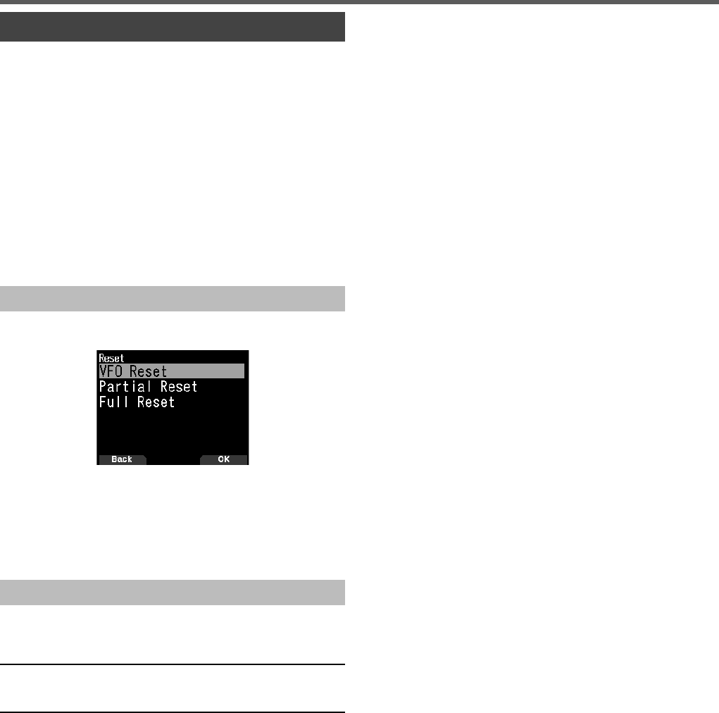
24
TRANSCEIVER RESET
There are 3 types of transceiver reset available:
VFO Reset
Use to initialize the VFO and accompanying settings.
Partial Reset
Use to initialize all settings other than the Memory channels,
and the DTMF memory channels.
Full Reset
Use to initialize all transceiver settings that you have
customized. (Date and time are not reset.)
There are 2 ways to perform a reset on the transceiver: by
key operation and by accessing Menu mode.
Key Operation
1 Turn the transceiver power OFF.
2 Press [F] + Power ON until reset screen appears.
3 Select your desired reset type: [VFO Reset], [Partial
Reset], or [Full Reset].
4 Press [A/B] to set the reset type.
A confi rmation message appears on the display.
5 Press [A/B] again to perform the reset.
Menu Mode
1 Access Menu No. 999.
2 Select your desired reset type: [VFO Reset], [Partial
Reset], or [Full Reset].
Note:
◆Press [PF2] + Power ON to set the voice guidance to
Auto1 after Full Reset.
OTHER OPERATIONS
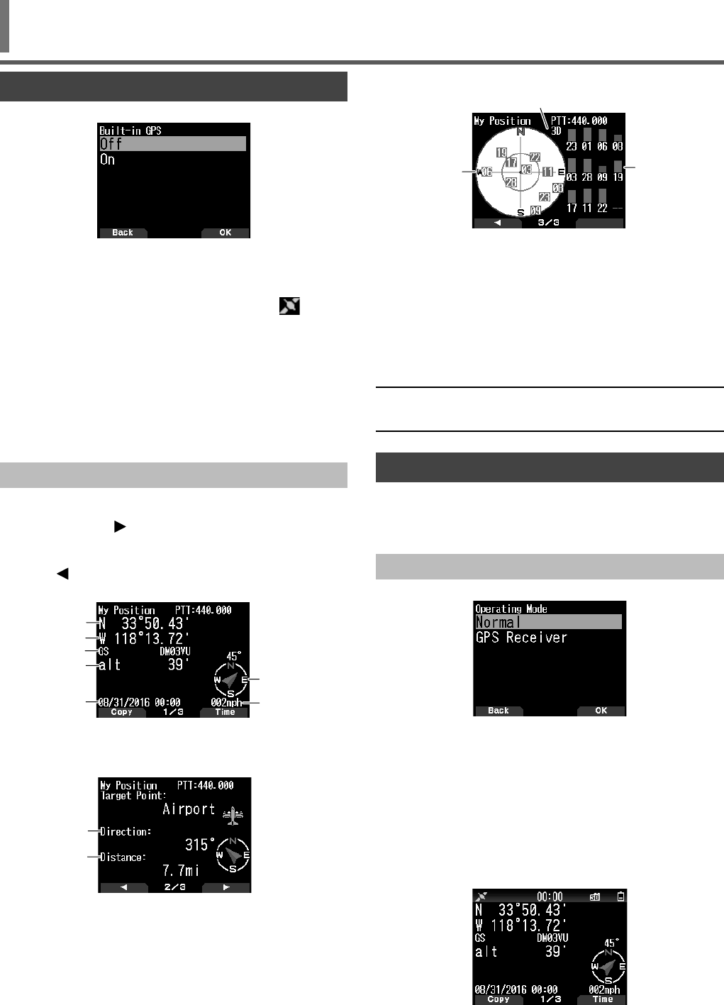
25
BUILT-IN GPS FUNCTION ON/OFF
1 Access Menu No. 400 and start the setting.
2 Select [On] or [Off].
[On]: Turns on the built-in GPS function.
[Off]: Turns off the built-in GPS function.
• When the built-in GPS receiver is On, the < >
indicator appears on the display and fl ashes during
positioning.
• You must set the time zone beforehand, through Menu
No. 950.
• When determining your position for the fi rst time
after the power supply is turned On, the clock data
is automatically set and is updated once per day
thereafter.
Displaying Position Information
When the built-in GPS receiver is On, pressing [F], [MARK]
will display “Latitude/longitude, time, altitude, heading,
speed”, then press [ ] to cycle the display between
“Latitude/longitude, time, altitude, heading, speed” ➡ “Target
point distance, Travel direction” ➡ “GPS satellite information”.
• Press [ ] returns to the previous display.
Latitude/longitude, Time, Altitude, Heading, Speed
a
b
c
d
g
e
f
a Latitude b Longitude c Grid square locator d Altitude
e Time f Heading g Speed
Target point distance, Target direction
a
b
a Target direction b Target point distance
•
When pressing [F] while the target point distance/ target
direction is displayed, the North Up display (displays North
as the top) changes to the Heading Up display (displays
the current travel direction as the top) or vice-versa. In the
Heading Up display, a “+” or “-” is used to help indicate the
traveling direction.
GPS satellite information
b
a
c
a Sky view b Satellite signal-strength bars
c 2D: Latitude/Longitude positioning
3D: Latitude/Longitude and Altitude positioning
•
The sky view shows the satellites you are receiving. The
satellite signal-strength bars indicate the strength of each
satellite you are receiving. A solid bar indicates that the
GPS satellite is ready for use.
•
When only the frame of the signal-strength bar is displayed,
no contact with the satellite has yet been made
Note:
◆When GPS cannot be received, turn the power ON in a clear
environment (Open Sky).
BUILT-IN GPS SETUP
You can select whether to use the transceiver function
together with the built-in GPS receiver function or to use the
built-in GPS receiver function only.
Built-in GPS Operation Mode
1 Access Menu No. 403.
2 Select [Normal] or [GPS Receiver].
Restart information appears.
3 Press [A/B] to restart the transceiver with the selected
mode.
[Normal]: The display continues to show your frequency.
You can use it as a normal transceiver.
[GPS Receiver]: The display shows only GPS information.
The transceiver transmit and receive capabilities are
turned OFF, and only GPS operation is available.
GPS Receiver mode display
GPS
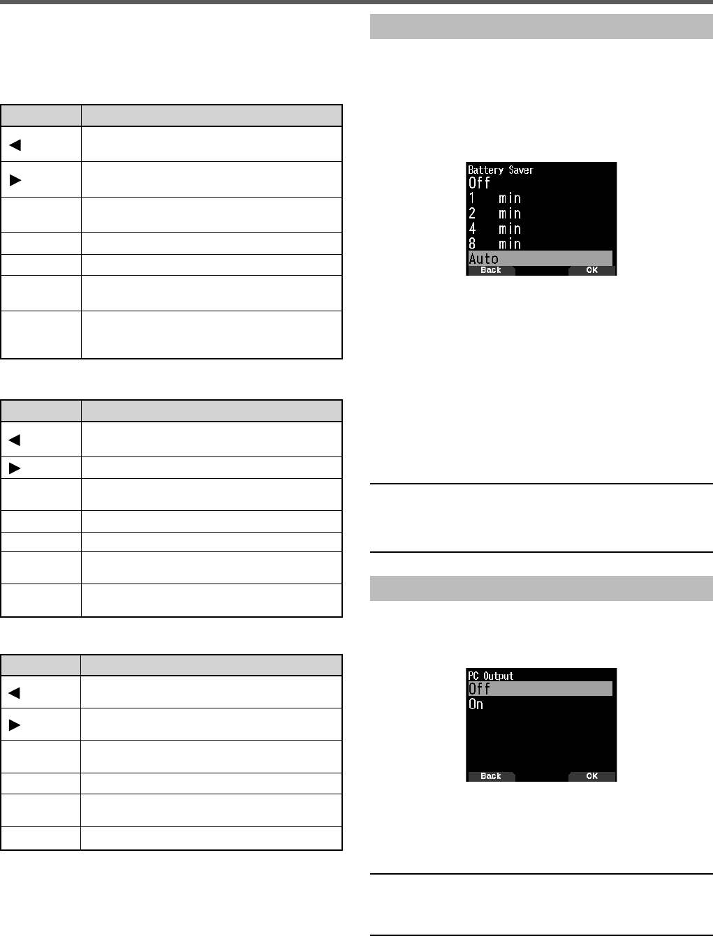
26
Key Operation in GPS Receiver Mode
When set to “GPS Receiver”, you can operate only the
following key functions.
Key operations in
[Latitude/longtitude, Time, Altitude, Heading, Speed]
Key Name Operation
[ ] Switches to FM radio frequency screen when FM
radio mode is On.
[ ] Switches to [Target point distance and Heading]
screen.
[MODE] Switches to [Latitude and Longitude] copy
selection screen.
[MENU] Switches to the menu screen.
[A/B] Switches to [Time] copy confi rmation screen.
[F] Switches between the North up and the Heading
up.
[MARK]
Press [MARK]: Switches Mark waypoint list.
Press [MARK] (1s): Switches to the registration
mode of mark position.
Key operations in [Target point distance, Target direction]
Key Name Operation
[]Switches to [Time, Altitude, Heading, and Speed]
screen.
[] Switches to [GPS satellite information] screen.
[MODE] Switches to [Time, Altitude, Heading, and
Speed] screen.
[MENU] Switches to the menu screen.
[A/B] Switches to [GPS satellite information] screen.
[F] Switches between the North up and the Heading
up.
[MARK] Press [MARK] (1s): Switches to the registration
mode of mark position.
Key operations in [GPS satellite information]
Key Name Operation
[]Switches to [Target point distance and Target
direction] screen.
[]Switches to FM radio frequency screen when FM
radio mode is On.
[MODE] Switches to [Target point distance and Target
direction] screen.
[MENU] Switches to the menu screen.
[A/B] Switches to FM radio frequency screen when FM
radio mode is On.
[MARK] Switches to the registration mode of mark position.
Battery Saver (GPS Save)
This function will turn the GPS power source Off after the
programmed timer expires if position data is not determined
during the maximum catching time (approximately 5 minutes).
To prevent unnecessary battery consumption, when there are
many reception satellites, the GPS is stabilized and position
data can be determined, the GPS power source repeatedly
turns On and Off.
1 Access Menu No. 404.
2 Set GPS Off time to [Off], [1], [2], [4], [8], or [Auto].
[OFF]: The built-in GPS receiver function is always On.
[1min] to [8min]: When set to 1, 2, 4, or 8 minutes, the
GPS off time starts at the selected duration if position
data is not determined during the maximum catching time
(approximately 5 minutes).
[Auto]: When set to Auto, the GPS Off time starts at 1
minute for the fi rst time, then progresses to 2 minutes,
4 minutes and 8 minutes each additional time. The GPS
Off time remains at 8 minutes thereafter. However, after
having determined your position for the duration, if the
GPS cannot pinpoint your location, the GPS Off time will
restart at 1 minute.
Note:
◆Position precision may be improved by setting the Batter Saver
(GPS Save) function to “Off”.
◆When GPS cannot be received, turn the power ON in a clear
environment (Open Sky).
GPS Data PC Output
Turn this function on when you want to send the built-in GPS
receiver data (NMEA) from the Micro-USB connector or
Bluetooth.
1 Access Menu No. 405.
2 Set PC Output to [Off] or [On].
[Off]: The built-in GPS receiver data (NMEA) is not output
from the Micro-USB connector or Bluetooth.
[On] The built-in GPS receiver data (NMEA) is output from
the Micro-USB connector or Bluetooth.
Note:
◆When the built-in GPS receiver data (NMEA) is output, the
communication speed (baud rate) is fi xed to 9,600 bps.
◆You can select USB or Bluetooth by Menu No. 981.
GPS
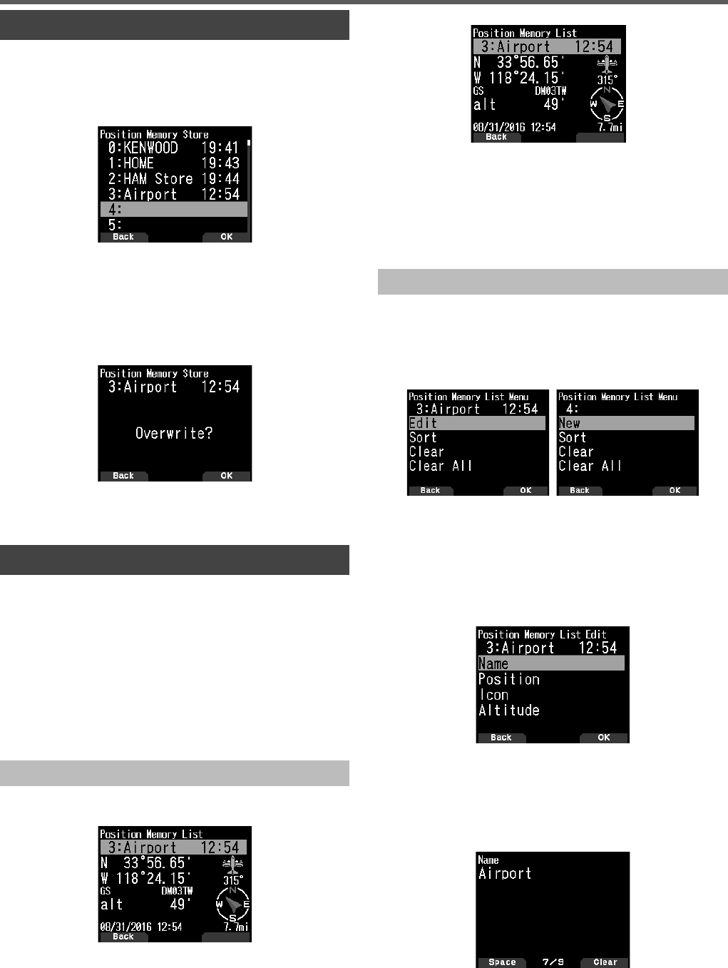
27
MARK FUNCTION
You can register up to 100 points with the location’s latitude,
longitude, altitude, time, name, and icon in the Position
Memory List.
1 Press [MARK] (1s).
The position memory store screen appears.
2 Select a position memory number.
3 Press [ENT].
The location information is registered.
When Overwriting
When selecting the already registered position memory
number, the overwrite confi rmation screen appears.
4 Press [A/B].
The location information is overwritten.
POSITION MEMORY LIST
You can register the following location information up to 100
points in the Position Memory List.
You can edit all information except Registration time manually.
• Position name
• Icon (APRS)
• Registration time
• Longitude
• Latitude
• Altitude
Checking Registered Position Memory
1 Press [MARK].
The position memory list screen appears.
2 Select a list.
3 Press [ENT].
The position memory list details screen appears. Details of
the position memory can be checked.
• When pressing [F], the North Up display (displays
North as the top) changes to the Heading Up display
(displays the current travel direction as the top) or vice-
versa.
4 Press [MODE].
The position memory list screen reappears.
Editing Position Memory
1 Press [MARK].
The position memory list screen appears.
2 Select a list.
3 Press [MENU].
The position memory list menu screen appears.
4 Select [Edit] or [New] and press [A/B].
The mode changes to position memory edit mode. The
edit menu items are as follows.
• Name (position name)
• Position (latitude and longitude)
• Icon
• Altitude
Editing the Name (Position Name)
1 Select [Name] and press [A/B].
The character input screen appears.
2 Select the characters.
For the detailed character input procedure, refer to page 15.
GPS
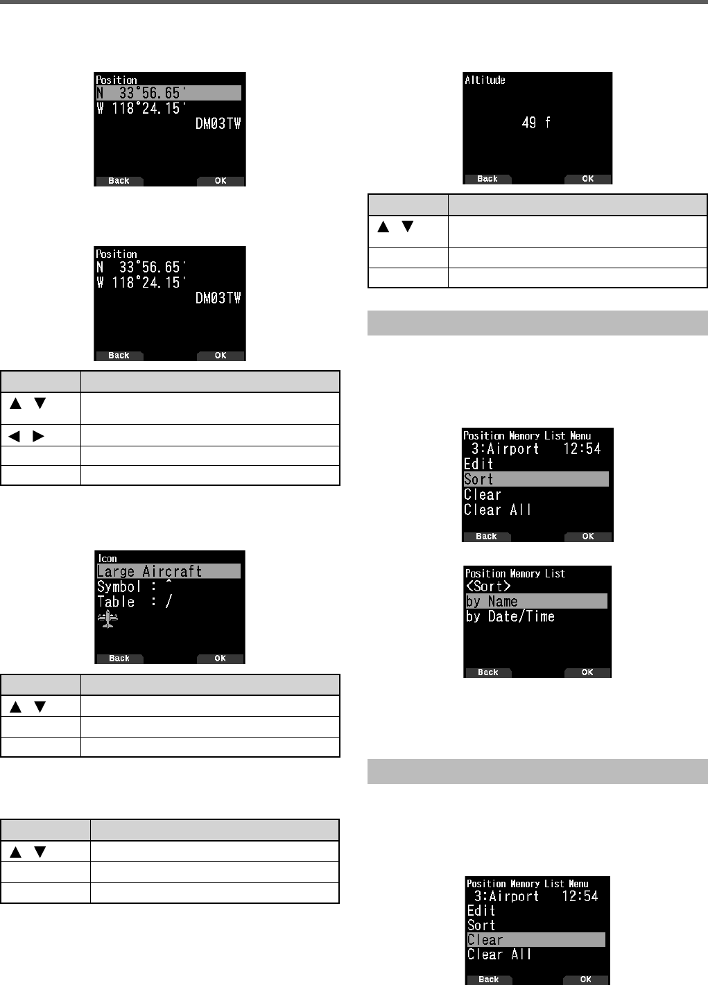
28
Editing the Position (Latitude and Longitude)
1 Select [Position] and press [A/B].
The mode changes to the latitude and longitude edit mode.
2 Select [N] or [W], and press [ENT].
[N]: Edits the latitude.
[W]: Edits the longitude.
Key Name Operation
[]/[ ] or
[ENC] Changes the item.
[]/[ ] Moves the cursor.
[ENT] Confi rms the editing.
[MODE] Cancels editing and returns to the previous screen.
Editing the Icon
1 Select [Icon] and press [A/B].
The mode changes to the icon setting mode.
Key Name Operation
[]/[ ] Switches the station icon.
[ENT] Cursor moves to [Symbol].
[A/B] Confi rms the station icon.
2 Select [Symbol] or [Table] and press [ENT].
[Symbol]: Edits the symbol.
[Table]: Edits the table code.
Key Name Operation
[]/[ ] Switches to [Symbol] or [Table].
[ENT] or [A/B] Changes to the selected setting mode.
[MODE] Returns to the station icon selection.
Editing the Altitude
1 Select [Altitude] and press [A/B].
The mode changes to the altitude setting mode.
Key Name Operation
[]/[ ] or
[ENC] Changes the item.
[ENT] Confi rms the editing.
[MODE] Cancels editing and returns to the previous screen.
Sorting Position Memory List
1 Press [MARK].
The position memory list screen appears.
2 Select a list.
3 Press [MENU].
The position memory list menu screen appears.
4 Select [Sort] and press [A/B].
5 Select [by Name] or [by Date/Time] and press [A/B].
[by Name]: Sorts in name order.
[by Date/Time]: Sorts in date and time order.
Clearing Position Memory
1 Press [MARK].
The position memory list screen appears.
2 Select a list.
3 Press [MENU].
The position memory list menu mode screen appears.
GPS
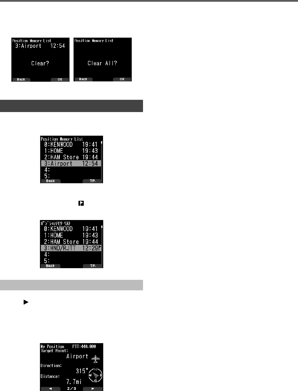
29
4 Select [Clear] or [Clear All] and press [A/B].
The clear confi rmation screen appears.
[Clear]: Clears the selected position memory.
[Clear All]: Clears all position memories.
6 Press [A/B] to clear the position memory.
TARGET POINT
You can register positional information for a target point.
1 Press [MARK].
The position memory list screen appears.
2 Select a position memory number.
3 Press [A/B].
The “in use” target point mark [] appears to the right of
the time. The target point mark disappears when pressing
[A/B] again.
Target point distance and Target direction
1 Press [F], [MARK]
2 Press
[ ].
[Target point distance and Target direction screen]
appears. When pressing [F] while the target point distance
and target direction are displayed, the North Up display
(displays North as the top) changes to the Heading Up
display (displays the current travel direction as the top) or
vice-versa.
GPS
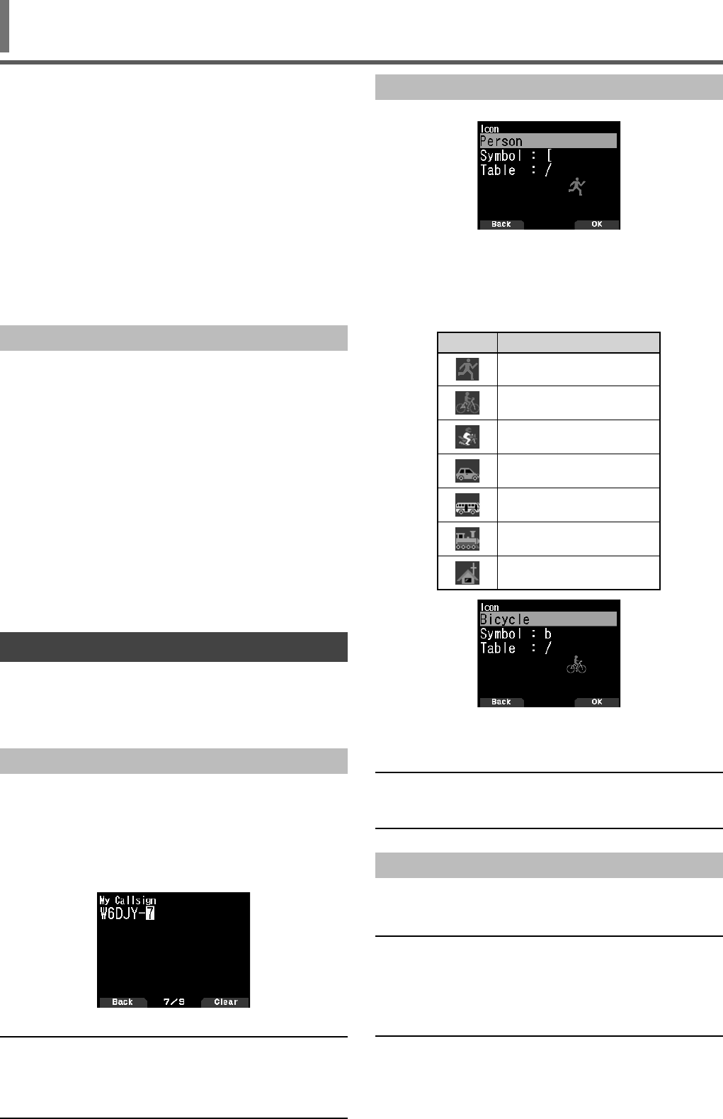
30
APRS®
APRS DATA COMMUNICATION
• This function uses the APRS format for data
communications including your station position, messages,
etc.
• When data is received from another station directly, via
digipeaters and/or IGate stations, the direction of the
received station (from your station’s perspective), their
distance, and their grid square locator is displayed. Any
comments sent by the other stations are also displayed.
• APRS (Automatic Packet Reporting System) is a
worldwide system introduced by Bob Bruninga, WB4APR.
< APRS® is a software program and registered trademark
of Bob Bruninga, WB4APR.>
Offi cial APRS Website: http://www.aprs.org
APRS Network
Digipeater
• Digipeater (Digital Repeater) relays digital packet data.
When a Digipeater receives a packet, it saves it to
memory. When the reception ends, the packet data is re-
transmitted on the same frequency. Using Digipeaters, it is
possible to exchange APRS packets long distances.
IGate
• IGate (Internet Gateway) is a very useful and important
feature for APRS as well as Digipeater. IGate stations
bridge APRS packets between RF and the Internet.
By going through the IGate stations, you can enjoy the
communication with the further distant stations which are
not covered only by Digipeaters.
Digipeater stations and IGate stations are operated by the
volunteer people in each region.
BASIC SETTINGS
This part covers only the minimum necessary settings for
basic operation as an APRS handheld portable station. Refer
to the User Manual (detailed instruction manual) on the
Website for more advanced settings.
My Callsign
Program your Callsign using a maximum of 9 alphanumeric
characters including SSID (Secondary Station IDentifi ers)
such as -7, -9, or -14. Unless you program a Callsign, you
cannot transmit APRS packets.
1 Access Menu No. 500.
The display for entering a Callsign appears.
You can enter 0 to 9, A to Z, and –.
2 Press [ENT] to set the Callsign.
Note:
◆For SSID characters, refer to the guideline on the Website (http://
aprs.org/aprs11/SSIDs.txt) by Bob Bruninga, WB4APR.
◆When all settings are blank, “NOCALL” is automatically set. In this
case, the Position packet (Beacon), Object Packet, or Message
packet cannot be transmitted.
Selecting your Station Icon
1 Access Menu No. 501.
2 Select an icon which will be displayed on the monitors
of other stations as your ID. You may select an icon
depending on your current location. It is important that the
icon conveys the operational status of the station as well
as the SSID.
Icon Examples
ICON Meaning
Person
Bicycle
Motorcycle
Car
Bus
Railroad Engine
Home
Bicycle icon selected
3 Press [A/B] to set your station icon.
Press [MENU] to return to the previous screen.
Note:
◆Set an icon that represents your operational status. (For example,
setting an Aircraft icon or Balloon icon to a fi xed station will cause
confusion when a station receives a beacon.)
Setting the Data Band Frequency
Set the data band frequency to the APRS network frequency.
The default setting of the data band is band A.
You can change the data band to band B by Menu No. 506.
Note:
◆The APRS network frequency will depend on what region of the
world you are operating as follows:
North America: 144.390 MHz, Europe: 144.800 MHz
Australia: 145.175 MHz, New Zealand: 144.575 MHz
Argentina: 144.930 MHz, Brazil: 145.570 MHz
Japan: 144.640 MHz (9600 bps)/ 144.660 MHz (1200 bps)
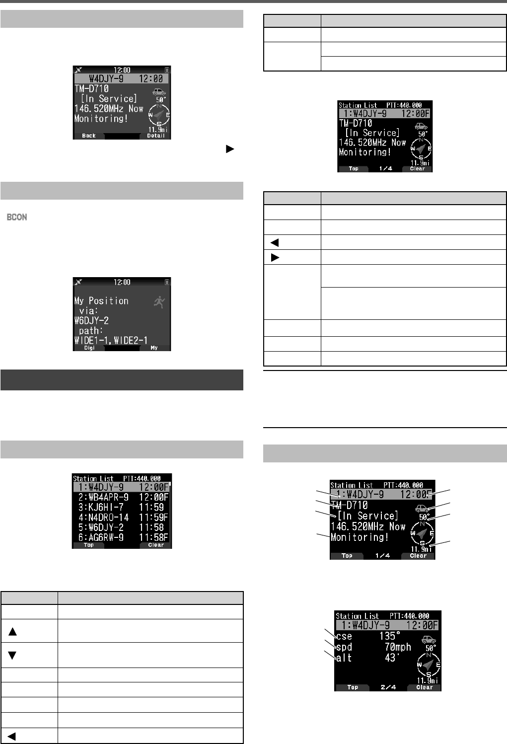
31
APRS®
Setting APRS Data Communication ON
Press [F], [LIST] to enter APRS mode.
Each time a new APRS packet is received, the frequency
display is interrupted to show information as below.
To return to the frequency screen, press any key except [ ]
or [A/B], or just wait for approximately 10 seconds.
Transmitting APRS Beacon
Press [BCN] to transmit your APRS beacon (position packet).
< > icon is displayed and APRS beacon is automatically
transmitted.
• When you receive an APRS beacon that you transmitted,
the frequency screen is interrupted and “My Position” will
appear on the display. This could happen when one or
more digipeaters are used.
ACCESSING RECEIVED APRS DATA
This transceiver is capable of receiving and storing APRS
data received from up to 100 stations in memory. You can
easily recall the information of the desired station.
Station List
1 Press [LIST] to show the list of stations.
2 Press [LIST] (1s) to change the list type to [Callsign +
model name], [Callsign + Time + QSY].
Key functions for station list are as follows.
Key Name Operation
[ENC] To select a station data.
[]To move the cursor to the small list number (New
receiving station).
[]To move the cursor to the big list number (Old
receiving station).
[ENT] To enter the details of the selected station.
[MODE] To move the cursor to the top list number.
[MENU] To enter the station list Menu.
[A/B] To delete the selected station data.
[]To return to the frequency display.
Key Name Operation
[PTT] To switch to the frequency display and transmit.
[LIST] To return to the frequency display.
Press [LIST] (1s): To change the list type.
3 Press [ENT] to select the desired station.
The details of station data are displayed.
Key functions for station data are as follows.
Key Name Operation
[ENC] To select a station data.
[MODE] To move the cursor to the top list number.
[]To return to the station list.
[]To display the next page.
[A/B]
To delete the selected station. When “Clear ?”
appears, press [ENT] to clear.
Press [A/B] (1s): To delete all stations. When
“Clear All ?” appears, press [ENT]. And when
“Sure ?” appears, press [ENT] again to clear all.
[MENU] To enter the station list Menu.
[PTT] To switch to the frequency display and transmit.
[LIST] To return to the frequency display.
Note:
◆When data from the 101st station is received, the oldest data in
memory is replaced by that data.
◆Each time a new APRS packet is received from the same station,
the old data from that station (in memory) is replaced by new
data.
Display Examples (Mobile station)
Page 1:
a
b
c
d
e
f
g
h
a Callsign b Situation c Position comment d Status text
e Time f Station icon g Direction of the station
h Distance from the station
Page 2:
a
b
c
a Moving direction b Moving speed c Altitude
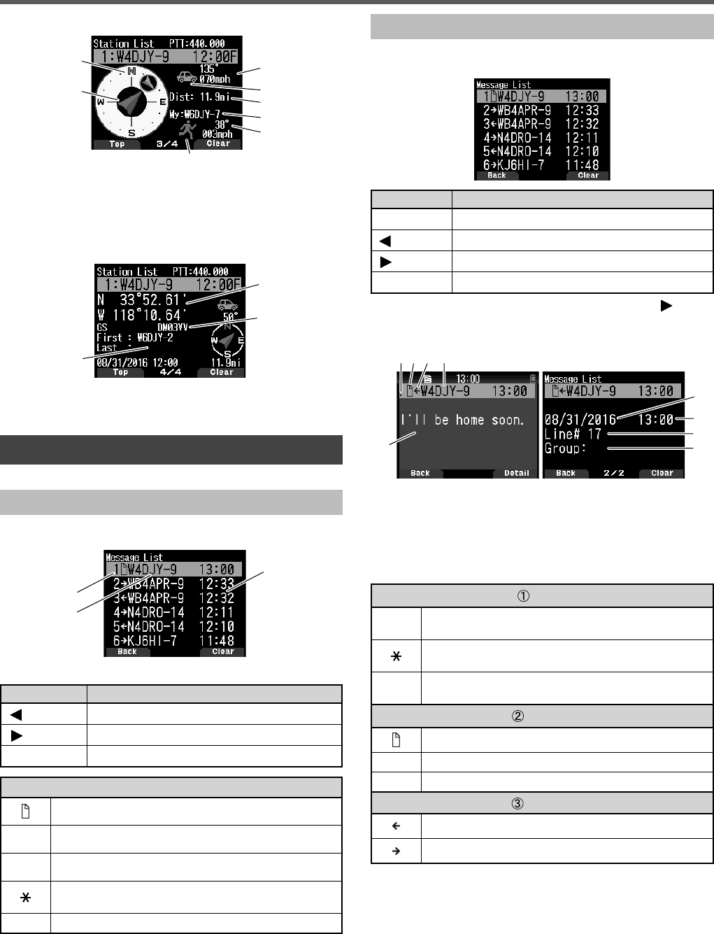
32
APRS®
Page 3:
a
b
c
d
e
f
g
h
a Moving direction of the other station b Moving direction
c Speed and moving direction of the other station
d Station icon of the other station e Distance from
the other station f My Callsign g Speed and moving
direction of my station h My station icon
Page 4:
a
b
c
a Latitude, Longtitude b Grid square locator c Packet
path (Digipeated route)
APRS MESSAGE FUNCTIONS
Receiving a Message
Each time a proper message is received, the frequency
display is interrupted to show information as below:
a
b
c
a Meaning indicator b Callsign (Sender) c Message
Key Name Operation
[]/ [MODE] To return to the frequency screen.
[]To move to the detail screen.
[A/B] To move to the message screen.
Meaning
Message addressed to you
B Bulletin message
!Report by the National Weather Service
A message for which a reception acknowledgment was
returned
G Group message
• When a duplicate message from the same station is
received, the reception interrupt display does not appear
and an error tone sounds. When the frequency at that time
appears on the display, “dM” (duplicate Message) and the
calling station's Callsign appears on the display.
Entering a Message
1 Press [MSG].
The message list appears on the display.
Key Name Operation
[ENC] To select a list number.
[]To return to the frequency screen.
[]To move to the detail screen.
[A/B] To delete the message on the cursor.
2 Select a list number by [ENC] control and press [ ].
The message list Menu appears on the display.
First page: Last page:
ab c d
e
g
h
f
i
a Status b Meaning indicator c Receiving message/
sending message d Callsign e Message f Receive date
g Receive time h Line number i Message group
• The display shows up to 67 characters of the message.
• The following indicators appear depending on the types
of received messages.
Status
n“n” indicates the remaining number of times for
transmitting the message
A message for which a reception acknowledgment was
returned
.A message transmitted 5 times (For a message, a
reception acknowledgment was not returned.)
Meaning
Message addressed to you
B Bulletin message
!Report by the National Weather Service
RX or TX
Received message
A message for transmitting
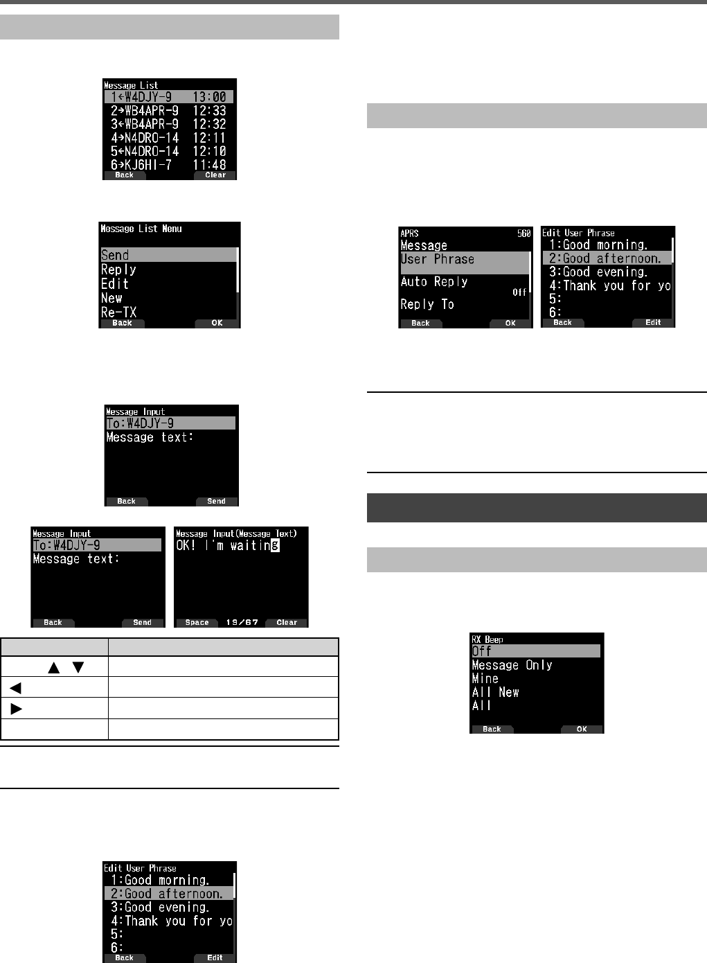
33
APRS®
Transmitting a Message
1 Press [MSG].
The message list appears on the display.
2 Press [MENU].
The message list Menu appears on the display.
3 Select [Reply], [Edit], or [New].
• When selecting [Edit], the original message is quoted
and you can edit it.
• Enter the Callsign when selecting [New].
4 Enter the message
Key Name Operation
[ENC]/ [ ]/[ ] To select a character.
[]To move the cursor backward.
[]To move the cursor forward.
[A/B] To delete the message on the cursor.
Note:
◆When using the already registered user phrases, refer to the
following step 5.
5 Enter the user phrase.
Press [F] to enter the message compilation mode.
You can select the user phrase among the already
registered user phrases by Menu No.560.
6 Select [Send] and press [A/B] to send the message.
You can select the following items other than [Send],
[Reply], [Edit], and [New] in message list Menu.
[Re-TX]: Send the message again.
[Position]: Search position information from a position list.
[POS Request]: The position data of the transmitting
station is displayed (if the station data is available).
[Unread]: Change the existing reading message to unread
message.
Storing User Phrases
This function (clipboard image) allows you to paste phrases
into the APRS message compilation mode. You can create
up to 20 phrases each of which can consist of up to 32
characters.
1 Access Menu No. 560.
You can select from user phrase 1 to user phrase 20.
2 Press [ENT].
3 Store user phrase.
4 press [ENT].
Note:
◆The user phrase function can only be used in the message
compilation mode.
◆Before a message is copied, the number of letters cannot be
guaranteed. Only the number of letters available will be copied,
and the remainder will be truncated.
SETTING NOTIFICATION SOUND
RX Beep Type
This transceiver beeps each time it receives any type of
APRS packets.
1 Access Menu No. 570.
[On]: The APRS beep tone does not sound.
[Message Only]: Beep sounds only when a message is
received at your station address.
[Mine]: Beep sounds when a message is received at your
station address and your transmitted data is received by a
digipeater.
[All New]: Beep sounds when a message is received at
your station address and new packet data is received.
[All]: Beep sounds when a message is received at your
station address and duplicate data or invalid data is
received.
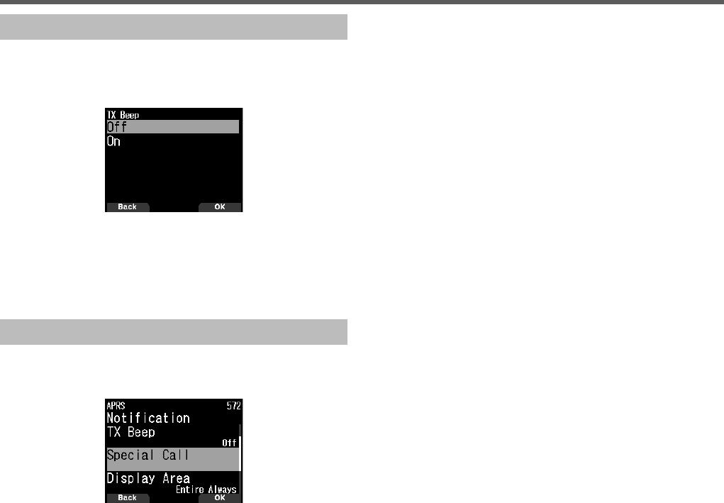
34
TX Beep
When your beacon is transmitted in a manner other than
manually, you can select whether or not it emits a beep
sound.
1 Access Menu No. 571.
[Off]: A beep does not sound.
[On]: A beep sounds when a beacon is transmitted using
the PTT switch or when it is automatically transmitted.
When auto-reply message sends a response, a beep will
sound.
Special Call
This function emits a special call sound when receiving an
APRS message from a specifi c station.
1 Access Menu No. 572.
2 Set the Callsign (including SSID) of the station from which
you want to receive a special call notifi cation.
APRS®
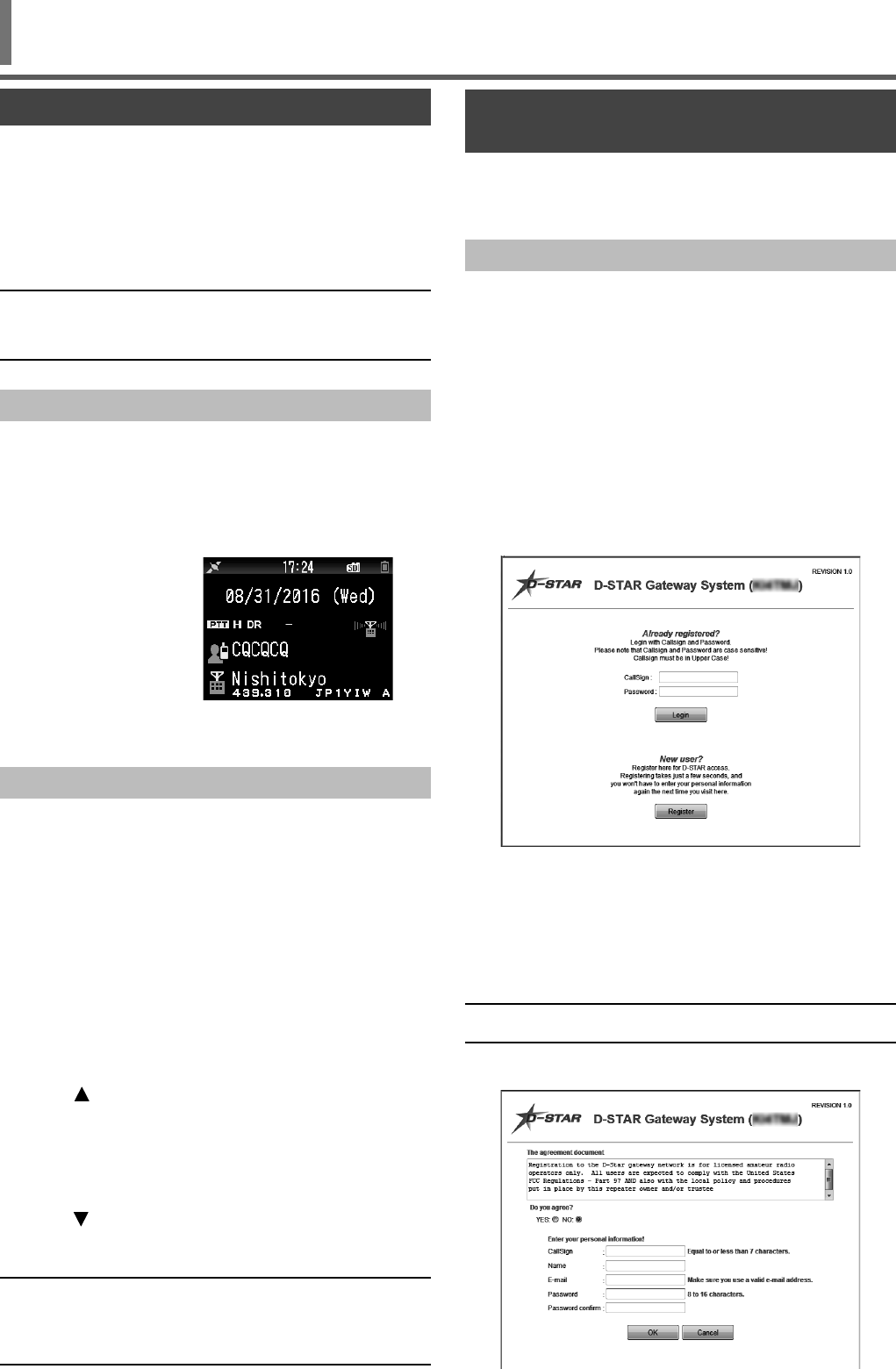
35
D-STAR
D-STAR INTRODUCTION
• In the original D-STAR (Digital Smart Technologies for
Amateur Radio) plan, JARL envisioned a system of
repeaters grouped together into Zones.
• The D-STAR repeater enables you to call a D-STAR
station in another area through the internet.
• The transceiver can be operated in the digital voice mode,
including low-speed data operation, for both transmit and
receive.
Note:
◆Before starting D-STAR, the following steps are needed.
STEP 1: Enter your Callsign in the transceiver.
STEP 2: Register your Callsign to a gateway repeater.
DV Mode/DR (D-STAR Repeater) Mode
DV (Digital Voice) mode is a mode you can use for direct call
without using a repeater.
DR (D-STAR Repeater) mode is a mode you can use for
D-STAR repeater operation. In this mode, you can select the
preprogrammed repeater or frequency in “FROM” (access
repeater), and UR Callsign in “TO” (destination), as shown
below.
TO: Destination
(CQ/Other area
repeater/Specifi c
station)
FROM: Access
repeater
➡
➡
DR mode (Main band)
Communication in DR mode
In the DR mode, the transceiver has 3 communication ways.
Local area call
• To call through your local area (access) repeater.
Gateway call
• To call through your local area (access) repeater, repeater
gateway and the internet to your destination repeater
or individual station’s last used repeater, using Callsign
routing.
Call by Callsign designation
• To call by designating the Callsign of the specifi c station.
This call is relayed automatically to the last accessed
repeater.
Basic operations in DR mode
• Press [ ] (1s) to set “TO” (destination).
You can set "TO" in Local area call, Gateway call, and Call
by Callsign designation, etc.
• Press [ENT] (1s) to set “TO” (destination) by Call
History.
You can recall in Gateway call, etc.
• Press [ ] (1s) to set “FROM” (access repeater).
You can select "FROM" (access repeater) in Local area
call and Gateway call.
Note:
◆The basic operations in DR mode are not supported in DV mode.
◆The transceiver has a Time-Out Timer function for digital
repeater operation. The timer limits a continuous transmission to
approximately 10 minutes.
REGISTER YOUR CALLSIGN AT A GATEWAY
REPEATER
To use the Internet, you must register your Callsign with a
repeater that has a gateway, usually one near your home
location.
Registration Process
This section describes the Callsign registration process at a
repeater that is connected to the US Trust server.
There are other systems as well, and they have their own
registration process. For information on how to register on
one of them, contact the administrator of a repeater that uses
the alternate system.
If necessary, ask the gateway repeater administrator for
Callsign registration instructions.
1 Access the following URL to fi nd the gateway repeater
closest to you.
http://www.dstarusers.org/repeaters.php
2 Click the Callsign of the repeater that you want to register
to.
3 Click the “Gateway Registration URL:” link address.
4 The “D-STAR Gateway System” screen appears.
Click [Register] to start the New User registration.
5 Follow the registration instructions on the registration
screen.
6 When you receive a notifi cation from the administrator,
your Callsign registration has been approved, but the
whole process is not yet complete.
Note:
◆It may take a few days for the administrator to approve you.
7 After your registration is approved, log in your personal
account with your registered Callsign and password.
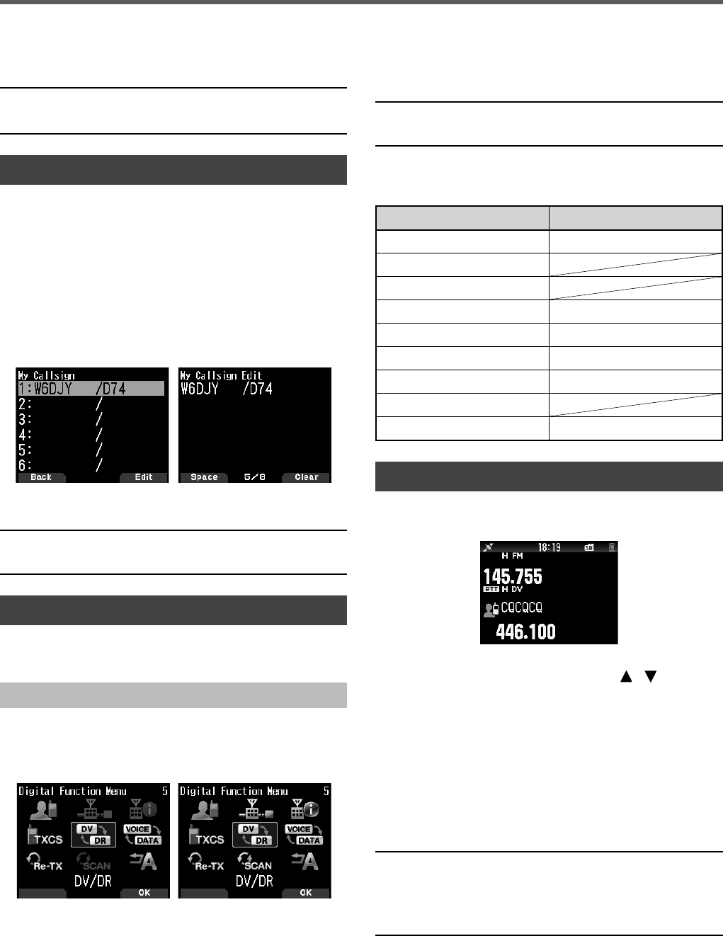
36
D-STAR
8 Register your D-STAR equipment information. Ask the
gateway repeater administrator for details.
9 When your registration is complete, log out of your
personal account, and start using the D-STAR network.
Note:
◆You must register your D-STAR equipment before you can make
calls through the gateway.
MY CALLSIGN
Set your Callsign to the transceiver in DV/DR mode.
Transmission in DV/DR mode will not be possible if you do
not set your Callsign.
Up to 6 Callsigns can be registered. For your Callsign, you
can register a Callsign that is within 8 characters and any
memo (name or rig name, mobile operation destination, etc.)
that is within 4 characters after a slash (/).
1 Access Menu No. 610.
2 Select a number for registration and press [A/B].
3 Input your Callsign.
• For the character input procedure, refer to page 15.
4 Press [ENT].
Your Callsign is set.
Note:
◆The Callsign that can be registered is the one shown on your
certifi cate. A nickname or the like cannot be registered.
DIGITAL FUNCTION MENU
This menu switches the functions to use for operation in
digital mode.
How to Use the Digital Function Menu
1 Press [MODE] to enter DR mode.
2 Press [F], [MODE].
The Digital Function Menu appears.
(DV mode) (DR Mode)
3 Select an item in the Digital Function Menu and press
[A/B].
The setting menu for the selected item appears. For the
detailed setting procedures, refer to the pages for each
function.
Note:
◆If you select DV/DR or Data Mode, the setting is changed and
return to the previous screen.
The following table shows the items in the Digital Function
Menu in DV mode and DR mode.
The items are different in DV mode and DR mode.
DR mode DV mode
1 Destination Select 1 Destination Select
2 Route Select
3 Repeater Detail
4 CS Setting 4 CS Setting
5 DV/DR 5 DV/DR
6 Data Mode 6 Data Mode
7 TX History 7 TX History
8 DR Scan
9 Auto Reply 9 Auto Reply
SIMPLEX CALL
Simplex call can be used for direct communication between a
pair of transceivers without using a repeater. Simplex call can
be operated only in DV mode.
Example: Outputting CQ at 446.100 MHz
1 Set the frequency to 446.100 MHz with []/[ ] or [ENC]
control.
2 Press [MODE] to enter DR mode.
When the mode is already DV mode, move to step 4.
3 Switch to DV mode in the Digital Function Menu.
4 Select [Destination Select] in the Digital Function Menu.
The destination selection screen appears.
5 Select [Local CQ] and press [ENT].
[CQCQCQ] is set to [TO].
6 Press [PTT] to transmit.
Note:
◆Receive at the frequency at which you will attempt to transmit and
check that there will be no interference with other stations.
◆When you set DV mode for the fi rst time, [CQCQCQ] is set to
[TO].
◆Simplex call in digital mode can be operated only in DV mode.

37
D-STAR
LOCAL AREA CALL
A local area call (local CQ) is the output of a CQ through only
one repeater. A call can be made by setting a local CQ to
"TO" and pressing [PTT].
Setting the Access Repeater (FROM)
1 Press [MODE] to enter DR mode.
2 Press
[ ] (1s).
The FROM selection screen appears.
3 Select [Repeater List] and press [ENT].
The world region, country, and group select screen
appears.
4 Select your area group and press [ENT].
The repeater list selection screen appears.
5 Select a nearby repeater from the repeater names or
state/prefecture names and press [ENT].
The access repeater is set to [FROM].
Setting the Local CQ (TO)
1 Press [ ] (1s).
The destination selection screen appears. This screen also
appears when selecting [Destination Select] in the Digital
Function Menu.
2 Select [Local CQ] and press [ENT].
CQCQCQ is set to [TO].
Checking Whether Signals Reach the Repeater
1 Press [PTT] (1s) and transmit.
2 Check the response.
If < > appears within 3 seconds, this indicates that
signals are reaching the repeater you are using and
signals are being output normally from the destination
repeater. However, <> does not appear if there is an
access from another station within 3 seconds. (Refer to the
chart on page 39 in detail.)
Transmitting
Press [PTT] to transmit.
GATEWAY CALL
A gateway call can be made by setting the area repeater to
output the CQ to [TO] and pressing [PTT].
A gateway CQ is the output of a CQ to an area that is
different from that of your station through a repeater
connected to the Internet. A call can also be made to an area
signals cannot directly reach because of the connection to
the Internet.
Setting the Access Repeater (FROM)
Set a near repeater to [TO].
Setting the Destination Repeater (TO)
1 Press [ ] (1s).
The destination selection screen appears. This screen also
appears when selecting [Destination Select] in the Digital
Function Menu.
2 Select [Gateway CQ] and press [ENT].
The repeater list appears.
3 Select the destination repeater and press [ENT].
The repeater is set to [TO].
Checking Whether Signals Reach the Repeater (TO)
1 Press [PTT] (1s) and transmit.
2 Check the response.
If < > appears within 3 seconds, this indicates that
signals are reaching the destination repeater through the
internet and signals are being output normally from the
destination repeater. However, < > does not appear if
there is an access from another station within 3 seconds.
Transmitting
Press [PTT] to transmit.
CALLSIGN DESIGNATION
A call by Callsign designation can be made by setting the
Callsign of the other party to [TO] and pressing PTT. A call
to the specifi c station is relayed automatically to the last
accessed repeater, so a call can be made without knowing
the area in which the other station is currently located.
Setting the Access Repeater (FROM)
Set a near repeater to [TO].
Setting the Destination (TO)
1 Press [ ] (1s).
The destination selection screen appears. This screen also
appears when selecting [Destination Select] in the Digital
Function Menu.
2 Select [Individual] and press [ENT].
The Callsign list appears.
3 Select the Callsign and press [ENT].
The individual Callsign and name are set to [TO].
4 Press [PTT] to transmit.
CALLSIGN LIST
Up to 300 Callsigns of the other stations can be registered.
Names and any memo can also be registered instead of
Callsigns. The registered names are displayed in the TX
History and RX History.
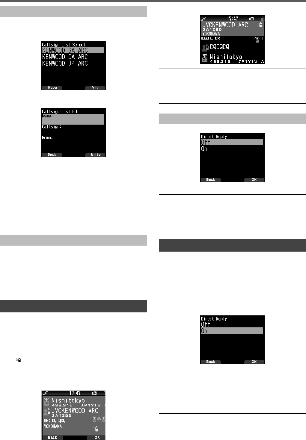
38
D-STAR
Half interrupt screen
Note:
◆The change of the transmission setting are temporary. After
display hold time elapses, it returns to the previous transmission
setting.
◆When receiving the repeater frequency in DV mode, you can not
reply to a received call by pressing [PTT].
Setting Direct Reply to Off
1 Access Menu No. 612.
2 Select [Off].
Note:
◆You can change the display hold time by Menu No. 643.
◆Direct reply is not possible when display method (Menu No. 640)
is set to [Off].
◆When the direct reply is set to [On], the interrupt screen of DV and
DR mode is displayed in priority than APRS mode.
CALL HISTORY
You can call easily by setting the received party to the
destination from a Call History even if you do not use a direct
reply function.
Up to 20 TX History and 100 RX History can be stored as
a Call History in DV and DR mode. The Call History is not
cleared when the power is switched [Off].
1 Press [MODE] to enter DR mode.
2 Press [ENT] (1s).
The Call History screen appears.
3 Select a list and press [ENT].
The transmission setting is changed and returns to the
frequency screen.
Note:
◆Pressing [ENT] (1s) does not work in DV mode. Press [F],
[MODE], select [Destination Select] in the Digital Function Menu,
and select Call History.
Editing the Callsign
You can edit the information of the Callsign.
1 Access Menu No. 220.
The Callsign list selection screen appears.
2 Press [A/B].
The Callsign list editing screen appears.
3 Select the item and press [ENT].
The editing screen for the selected item appears.
You can register or edit the name, Callsign, and memo,
etc.
4 Press [ENT] after editing.
Editing are completed and the Callsign list editing screen
appears.
5 Press [A/B].
The Callsign list selection screen appears.
Sorting the Callsign
You can sort the Callsign list.
1 Press [MODE] in the Callsign list selection screen.
The move position selection screen appears.
2 Select a move position and press [A/B].
When you move an item to the end of the list, select
[Move to End] and press [A/B].
DIRECT REPLY
This function allows you to reply to a received call by simply
pressing [PTT] while displaying the interrupt screen in DV
and DR mode. The default setting is [On]. When a repeater
signal is received in a DR mode and you immediately reply
to a CQ or a call to your Callsign, the transmission setting
is temporarily changed automatically and you can reply by
simply pressing [PTT].
The < > icon appears in the interrupt screen when a direct
reply is possible in receiving a call. If [PTT] is pressed when
this icon appears, the setting is automatically changed to the
reply setting and transmission becomes possible.
Entire interrupt screen

39
Chart for checking whether signals reach the repeater
Phenomenon Cause Treatment
No message is returned
from the access repeater
after transmission. (S-meter
indicator also does not
move.)
In case that the selection for the repeater you
are using (access repeater) is incorrect. Set the correct access repeater to [FROM].
In case that the repeater frequency is incorrect
(or the duplex setting is incorrect). Set the repeater frequency (or the duplex setting) correctly.
In case that it is out of the repeater area (or the
signal does not reach the repeater). Move to a location where the signal reaches the repeater or
access another repeater that the signal will reach.
The access repeater
Callsign and < >
appear after transmission.
In case that your Callsign is not registered
to the D-STAR management server or the
registered information is different.
Register your Callsign to the D-STAR management server or
check the registered information.
In case that the other station's Callsign is not
registered to the D-STAR management server
or the registered information is different.
Check the registration status of the other station's Callsign
on the D-STAR management server (only when the other
station is open in public.)
The destination repeater
Callsign and < >
appear after transmission.
In case that a destination repeater can not be
reached or the destination repeater is in use. Wait a while and call again.
D-STAR
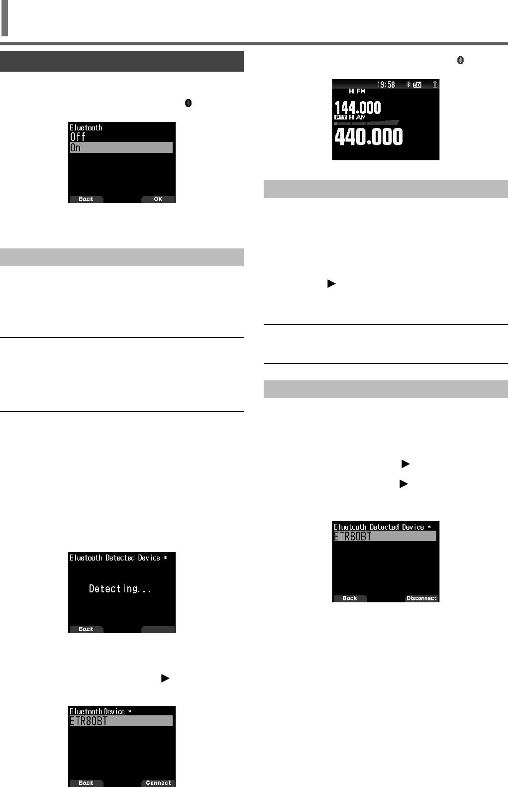
40
Bluetooth®
TURNING ON/OFF THE Bluetooth FUNCTION
You can turn On/ Off the Bluetooth function.
1 Access Menu No. 930.
When the Bluetooth function is turned on, < > appears
on the display.
[On]: Turns on the Bluetooth function.
[Off]: Turns off the Bluetooth function.
Connecting with a Headset (Pairing)
When connecting the transceiver with a Bluetooth compatible
device, you need to fi rst pair the devices. Pairing is a function
for registering devices for a Bluetooth connection as a
connection pair.
The following explains how to connect via Bluetooth using the
example of a commercially available headset.
Note:
◆For the device to be connected with the transceiver via Bluetooth,
be sure to purchase a headset or other device that is compatible
with Bluetooth. Also refer to the instruction manual of the device.
◆A connection may not be possible depending on the specifi cations
or settings of the device. There is no guarantee that the
transceiver will be able to communicate wirelessly with all
Bluetooth devices.
1 Access Menu No. 930 to turn on the Bluetooth function.
2 Place the headset (device to be connected) near the
transceiver.
• Place it within approximately 1 meter each other.
3 Set the headset (device to be connected) to the pairing
mode (Bluetooth connection standby state).
• For how to enable the pairing mode, refer to the
instruction manual of the headset (device to be
connected).
4 Access Menu No. 932. A device search begins and the
recognized device is added to the Bluetooth device search
list.
5 Select the device to be connected.
When connecting the device that is already selected, move
to step 6.
• If you select the device and press [], the Bluetooth
device information screen appears. You can confi rm the
device name, device address, and device class.
6 Press [A/B]. When the device is connected, < > appears
on the display.
Entering the PIN Code
When searching for the device, you may be requested to
enter the PIN code depending on the device to be connected.
When Requested to Enter the PIN Code
The PIN code input screen appears. Refer to the
instruction manual of the device to be connected and
enter the PIN code using the number keys and press
[A/B].
If you press [] when the PIN code input screen is
displayed, the Bluetooth device information screen
appears. You can confi rm the device name, device
address, and device class.
Note:
◆The PIN code differs depending on the device to be connected.
Refer to the instruction manual of the Bluetooth device and enter
the correct PIN code.
Disconnecting from a Bluetooth device
You can disconnect a connected Bluetooth device to stop
communication.
1 Access Menu No. 933.
2 Select the device.
• When disconnecting the device that is already selected,
move to step 3. If you press [], the Bluetooth device
information screen appears. If you select the device to
be disconnected and press [], the Bluetooth device
information screen appears. You can confi rm the device
name, device address, and device class. Pressing
[MODE] returns to the previous screen.
3 Press [A/B].
The disconnection process begins.
• If 30 seconds or more passes during the disconnection
process, the Bluetooth device disconnection failure
screen appears. Pressing [A/B] returns to the
frequency screen. Perform the procedure again from
step 1.
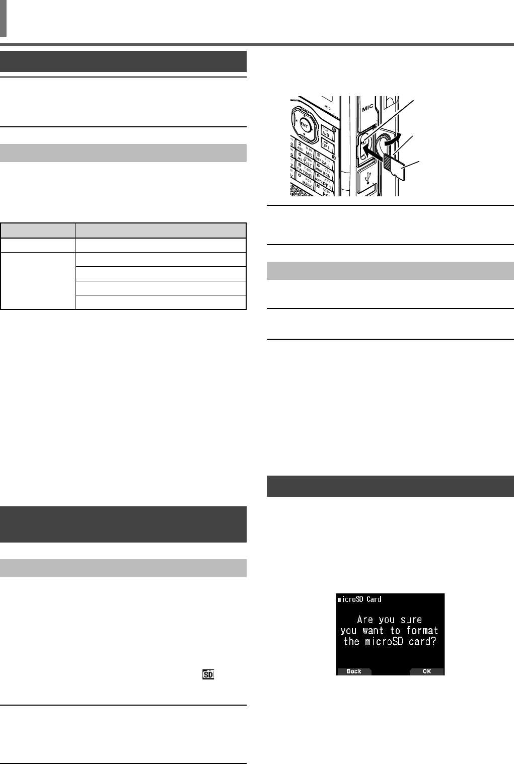
41
microSD MEMORY CARD
microSD MEMORY CARD
Note:
◆A microSD memory card or microSDHC memory card is not
supplied with this transceiver. Purchase a commercially available
product.
◆A microSDXC memory card can not be used with this transceiver.
Supported microSD Memory Card
The following table shows the microSD memory card and
microSDHC memory card for which JVC KENWOOD has
verifi ed operation.
In this manual, microSD memory cards and microSDHC
memory cards are referred to as microSD memory cards.
Memory Card Size
microSD 2 GB
microSDHC
4 GB
8 GB
16 GB
32 GB
• Regardless of the above table, JVC KENWOOD does not
guarantee the operation of all microSD memory cards.
• The operation of a microSD memory card formatted with
other than the transceiver is not guaranteed.
• The larger the capacity of the microSD memory card used,
the longer it takes to recognize the microSD memory card.
• Please note that the data in the microSD memory card may
be damaged or erased in cases such as the following.
• If the microSD memory card is removed without
performing the [Safely Remove] operation (unmount).
• If the battery pack or battery case is removed during
operation.
• If the battery pack or alkaline batteries run out of power
during operation.
• If the power from an external power supply suddenly
stops without installing the battery pack.
INSERTING/REMOVING A microSD MEMORY
CARD
Inserting (Mounting) a microSD Memory Card
1 Switch OFF the power of the transceiver.
2 Open the cap of the microSD memory card slot on the
side.
3 Insert the microSD memory card.
• With the contacts of the microSD memory card
atthe front, insert the microSD memory card into the
[microSD memory card slot] until you hear it lock
into place with a click. The transceiver automatically
recognizes the microSD memory card and < >
fl ashes on the display. It changes to always displayed if
the card enters the readable/writable state correctly.
Note:
◆When inserting a microSD memory card, do not touch its
contacts.
◆Do not remove a microSD memory card while data is being
written or read. Doing so may cause the data on the microSD
memory card to be damaged or erased.
4 Close the cap.
Close the cap of the microSD memory card slot on the
side properly.
microSD
Memory Card Slot
Cap
microSD
Memory Card
(insert the metal
contact side)
Note:
◆Do not insert a microSD memory card the opposite way around or
use force to insert it. Doing so may damage the microSD memory
card or slot.
Removing (Unmounting) a microSD Memory Card
When removing a microSD memory card, be sure to perform
the operation to safely remove (unmount) it.
Note:
◆Removing a microSD memory card without unmounting it
correctly may damage it.
1 Access Menu No. 820.
The microSD memory card is unmounted. When
unmounting is completed, the completed confi rmation
screen appears.
2 Press [A/B].
Unmounting completes and the frequency screen
reappears.
3 Remove the microSD memory card.
• When removing a microSD memory card, push until
you hear it unlock with a click and remove it.
FORMATTING A microSD MEMORY CARD
When using a new microSD memory card, format the
microSD memory card as described below. All the data in
the microSD memory card will be erased when the microSD
memory card is formatted.
1 Insert the microSD memory card into the transceiver.
2 Switch ON the power of the transceiver.
3 Access Menu No. 830.
The format confi rmation screen appears.
4 Press [A/B].
Formatting begins. When formatting is completed, the
completed confi rmation screen appears.
5 Press [A/B] again.
Formatting completes and the frequency screen
reappears.
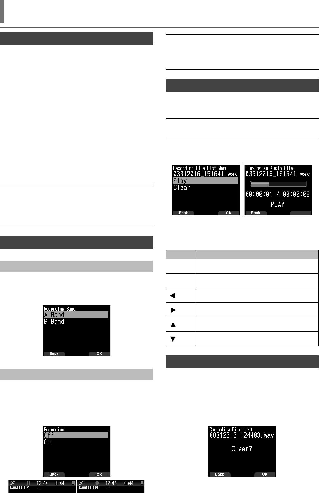
42
Note:
◆If there is no free space on the microSD memory card when
recording starts or after recording has been started, a warning
tone sounds and the insuffi cient microSD memory card space
screen appears. Replace the microSD memory card with another
one.
PLAYING AUDIO FILES
1 Access Menu No. 300.
The recording fi le list appears. Recorded audio fi les can
be played and cleared.
Note:
◆When the recording function is on, the recording fi le list does not
appear.
2 Select the fi le.
3 Press [MENU].
The recording fi le list menu appears.
4 Select [Play] and press [A/B].
Playback begins. When playback fi nishes, the recording
fi le list reappears.
Key Operations in playing audio fi les
Key Action
[ENT] Pauses playback. Pressing it again resumes
playback.
[MENU]Stops playback. Pressing it again returns to the
frequency screen.
[]Holding down performs fast reverse playback.
Releasing it resumes playback.
[]Holding down performs fast forward playback.
Releasing it resumes playback.
[]Plays the fi le immediately above the fi le selected in
the recording fi le list.
[]Plays the fi le immediately below the fi le selected in
the recording fi le list.
CLEARING AUDIO FILES
1 Access Menu No. 300.
The recording fi le list appears.
2 Select the fi le.
3 Press [MENU].
The recording fi le list menu appears.
4 Select [Clear] and press [A/B].
The recording fi le clear confi rmation screen appears.
5 Press [A/B].
The fi le is cleared and the recording fi le list reappears.
RECORDING FUNCTION
You can record communications to a microSD memory card.
• Recording is performed when transmitting and when the
squelch is open. When transmission stops or the squelch
closes, recording is paused.
• Up to approximately 18 hours (2 GB) can be recorded
to one fi le. When the fi le being recorded exceeds 2 GB,
recording continues with a new fi le.
• Recording fi les are named as follows.
Example: 12202016_132051.wav (TH-D74A)
20122016_132051.wav (TH-D74E)
(File for which recording started at 13:20:51 on
December 20, 2016.)
• The recording audio fi le format is WAV.
Number of bits: 16 bits
Sampling frequency: 16 kHz
Number of channels: 1 (monaural)
• If the auto power off (APO) time elapses during recording,
recording stops and turns the power OFF.
Note:
◆For how to insert a microSD memory card, refer to page 41.
◆The transceiver only supports recording to a microSD memory
card.
◆A microSD memory card or microSDHC memory card is not
supplied with this transceiver. Purchase a commercially available
product.
RECORDING AUDIO FILES
Selecting the Recording Band
Select the recording band A or B.
1 Access Menu No. 302.
[A Band]: Records the sound of the band A.
[B Band]: Records the sound of the band B.
Recording Communication Audio
Set the recording function on to start recording. Even if the
recording function is on, recording will not start while the
squelch is closed.
1 Access Menu No. 301.
[Off]: Turns off the recording function.
[On]: Turns on the recording function.
Recording
Recording paused
RECORDING
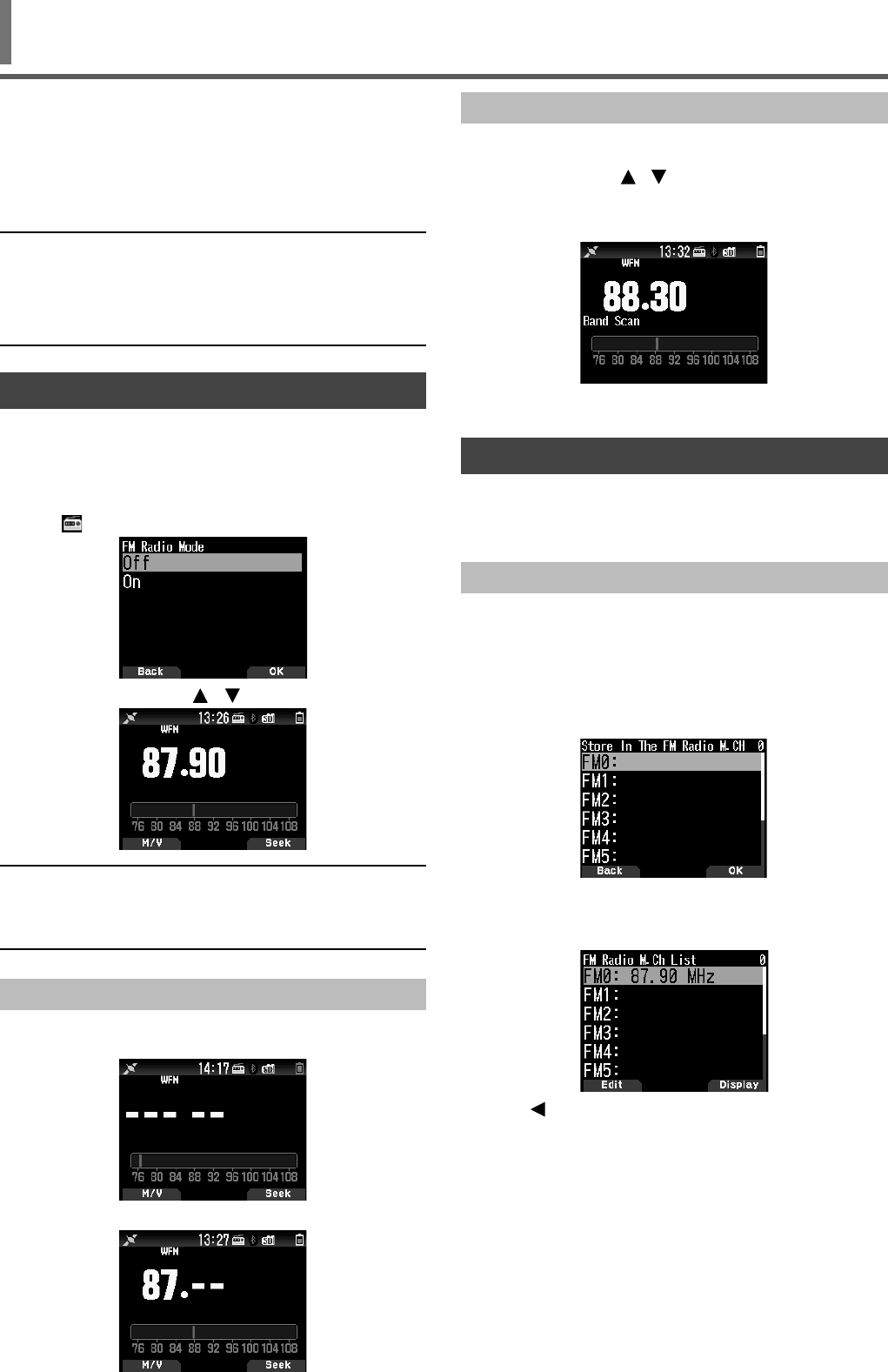
43
FM RADIO
The transceiver can receive FM radio broadcasts. You can
listen to FM radio while simultaneously monitoring two
signals as well as while waiting for a CQ or a call from an
acquaintance, or waiting for an APRS call. When the band A
or B receives a signal (call from another party) and squelch is
open, the radio sound is muted so that you can hear the other
party's voice.
Note:
◆You can not turn on the FM radio mode when selecting the
following frequency bands in band B. (LF/MF(AMBC), HF,
50, FMBC)
◆You can not turn on the FM radio mode when priority scan
(Menu No. 134) or WX alert is On (Menu No. 106).
TURNING ON FM RADIO MODE
1 Access Menu No. 700.
[On]: Turns on the FM radio function.
[Off]: Turns off the FM radio function.
When this is set to [On], the mode becomes FM radio
mode, the frequency screen appears, and the FM radio
icon < > appears.
2 Select a frequency with [ ]/[ ] or [ENC] control.
Note:
◆When receiving the signals for bands A and B while displaying FM
radio mode screen, the frequency screen for bands A and B or
interrupt screen appear. After the signal reception is fi nished, FM
radio mode screen appears again in a few seconds.
Frequency Direct Entry (Direct Station Selection)
1 Press [ENT].
The mode becomes frequency direct input mode.
2 Enter a frequency using the number keys.
Radio Scan
1 Press [A/B].
The MHz dot fl ashes and scanning begins. Change the
scan direction with [ / ] or [ENC] control. When a
broadcast station with a signal is found, scanning stops
at that frequency, <<Tuned>> is displayed and scanning
ends.
2 Press [A/B], and Radio scan stops.
EDITING THE FM RADIO MEMORY CHANNEL LIST
FM broadcast stations for up to ten channels can be
registered to the FM radio memory channel list. You can
assign names and edit the registered broadcast stations.
Registering FM Radio Stations
Register the FM radio stations you listen to frequently to FM
radio memory channels.
1 Switch to FM radio mode and select a broadcast station
you wish to register.
2 Press [F], [MR].
The store in the FM radio memory channel screen
appears.
3 Select the channel and press [ENT].
The FM radio station is registered and the FM radio
memory channel list appears.
4 Press [ ].
The frequency screen reappears.
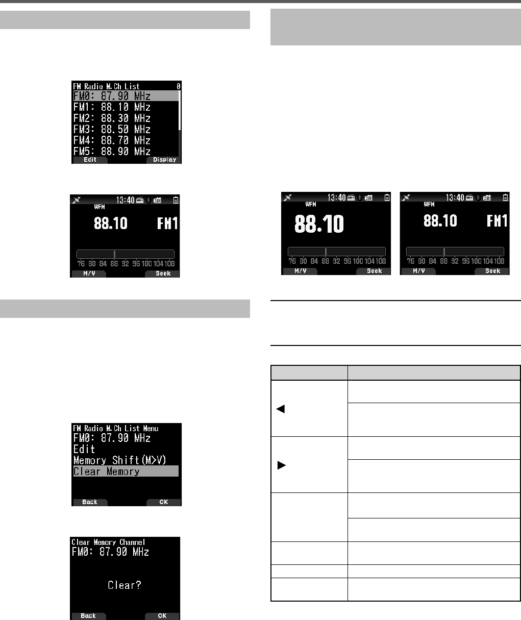
44
Selecting a FM Radio Station
Select a registered FM radio station from the FM radio
memory channel list.
1 Access Menu No. 710.
The FM radio memory channel list appears.
2 Select the channel and Press [ENT].
Select from FM0 to FM9.
Clearing FM Radio Stations
Clear the FM radio stations you do not listen to any more
from the FM radio memory channels.
1 Access Menu No. 710.
The FM radio memory channel list appears.
2 Select the channel you wish to clear.
Select from FM0 to FM9.
3 Press [MENU].
The FM radio memory channel list menu appears.
4 Select [Clear Memory] and press [A/B].
The FM radio memory clear confi rmation screen appears.
5 Press [A/B].
The FM radio station is cleared, and the FM radio memory
channel list menu reappears.
Switching Between FM Radio Mode and FM
Radio Memory Mode
FM radio mode
This mode allows you to receive an FM radio broadcast by
setting a frequency.
FM radio memory mode
This mode allows you to call up memory channels for which
frequencies have been registered in advance. A channel
indication from FM0 to FM9 is displayed in FM radio memory
mode.
1 Press [MODE].
Each press switches between FM radio mode and FM
radio memory mode.
FM radio memory modeFM radio mode
Note:
◆When no broadcast stations are registered in FM radio
memory channel list, you can not switch to the FM radio
memory mode.
Key Operations in FM Radio and FM Radio Memory Mode
Key Name Operation
[]
Pauses FM radio mode, and return to
FM radio mode after a few seconds.
Switches to [GPS satellite information]
screen when the GPS operation mode is
GPS Receiver mode.
[ ]
Pauses FM radio mode, and return to
FM radio mode after a few seconds.
Switches to [time, Altitude, Heading, and
Speed] screen when the GPS operation
mode is GPS Receiver mode.
[ENT]
Switches to frequency direct input mode.
(in FM radio mode)
Displays the FM radio memory channel
list. (in FM radio memory mode)
[MODE] Switches between FM radio mode and
FM radio memory mode.
[A/B] Performs a radio scan (Seek).
Keypad Pauses FM radio mode, and return to
FM radio mode after a few seconds.
FM RADIO

45
SPECIFICATIONS
TH-D74A/ TH-D74E SPECIFICATIONS
GENERAL
Band-A TX: 144 - 148 (TH-D74A), 144 - 146 (TH-D74E), 222 - 225 (TH-D74A),
430 - 450 (TH-D74A), 430 - 440 (TH-D74E) MHz
RX: 136 - 174, 216 - 260 (TH-D74A only), 410 - 470 MHz
Band-B RX: 0.1 - 76, 76 - 108 MHz (WFM)
108 - 524 MHz
Mode TX F3E, F2D, F1D, F7W
RX F3E, F2D, F1D, F7W, J3E, A3E, A1A
-20°C ~ +60°C (-4°F ~ +140°F)
with Incd. KNB-75L -10°C ~ +50°C (+14°F ~ +122°F)
Frequency Stability +/- 2.0 ppm
50 ȍ
DC-IN DC 11.0 - 15.9 V (STD: DC 13.8 V)
BATT DC 6.0 - 9.6 V (STD: DC 7.4 V)
TX EXT.PS 13.8 V / Battery:7.4 V
(TYP.) H M L EL
DC-IN 1.4 A 0.9 A 0.6 A 0.4 A
BATT 2.0 A 1.3 A 0.8 A 0.5 A
RX
(TYP.) SINGLE 260 mA (Rated Power)
135 mA (SQ Close)
48 mA (Avg. Save on)
DUAL 310 mA (Rated Power)
185 mA (SQ Close)
50 mA (Avg. Save on)
GPS logger mode 115 mA
HML EL
6 hours 8 hours 12 hours 15 hours
4 hours 5 hours 7 hours 9 hours
------ ------ 3.5 hours ------
Approx. 10 % shorter when GPS is ON
Projections not included
with KNB-75L 56.0 x 119.8 x 33.9 mm (2.20 x 4.72 x 1.33 in)
with KNB-74L 56.0 x 119.8 x 29.3 mm (2.20 x 4.72 x 1.15 in)
with KBP-9 56.0 x 119.8 x 36.0 mm (2.20 x 4.72 x 1.42 in)
Weight (net) Body only 202 g (7.13 oz)
with KNB-75L 345 g (12.2 oz
)
(w/ Antenna, Belt Clip)
with KNB-74L 315 g (11.1 oz
)
(w/ Antenna, Belt Clip)
with KBP-9 360 g (12.7 oz
)
(w/ Antenna, Belt Clip, AAAx6 Battery)
TRANSMITTER
RF Power Output EXT.PS 13.8 V / Battery:7.4 V
HML EL
5 W 2 W 0.5 W 0.05 W
Modulation FM Reactance Modulation
DV GMSK Reactance Modulation
FM +/-5.0kHz
NFM +/-2.5kHz
HI / MID -60 dBc or less
L -50 dBc or less
EL -40 dBc or less
2 kȍ
Current Consumption
Frequency Range
KNB-75L (1,800 mAh)
Operating Temp. Range
Antenna Impedance
Operating Voltage
Current Consumption
Battery Life Approx. Single, Save on, Rate 6:6:48 sec, GPS off
Spurious Emissions
Microphone Impedance
KNB-74L (1,100 mAh)
KBP-9 (Alkaline AAAx6)
Dimensions (W x H x D)
Modulation Deviation

46
SPECIFICATIONS
TH-D74A/ TH-D74E SPECIFICATIONS
RECEIVER Band A Band B
Circuitry
Double Super Heterodyne
Triple Super Heterodyne
1st IF 57.15 MHz 58.05 MHz
2nd IF 450 kHz 450 kHz
3rd IF J3E, A3E, A1A 10.8 kHz
Sensitivity (TYP.)
FM 12dB SINAD
FM/ NFM 144 MHz 0.18/ 0.22 uV 0.19/ 0.24 uV
FM/ NFM 220 MHz (TH-D74A only) 0.18/ 0.22 uV 0.20/ 0.25 uV
FM/ NFM 430 MHz 0.18/ 0.22 uV 0.20/ 0.25 uV
DV
144 MHz (TH-D74A) 0.22 uV 0.22 uV
144 MHz (TH-D74E) 0.20 uV 0.22 uV
220 MHz (TH-D74A only) 0.22 uV 0.24 uV
430 MHz 0.22 uV 0.22 uV
SSB 10 dB S/N 0.16 uV
AM 10 dB S/N 0.50 uV
AM 10 dB S/N
0.3 - 0.52 MHz 4 uV
0.52 - 1.8 MHz 1.59 uV
1.8 - 54 MHz 0.63 uV
54 - 76 MHz 1.12 uV
118 - 174 MHz 0.50 uV
200 - 250 MHz 0.63 uV
382 - 412 MHz 1.12 uV
415 - 524 MHz 1.12 uV
FM 12dB SINAD
28 - 54 MHz 0.32 uV
54 - 76 MHz 0.56 uV
118 - 144 MHz 0.36 uV 0.36 uV
148 - 175 MHz 0.36 uV
200 - 222 MHz 0.36 uV
225 - 250 MHz 0.36 uV
382 - 400 MHz 0.50 uV
400 - 412 MHz 0.36 uV 0.36 uV
415 - 430 MHz 0.36 uV 0.36 uV
450 - 490 MHz 0.36 uV 0.36 uV
490 - 524 MHz 0.63 uV
SSB 10 dB S/N
1.8 - 54 MHz 0.40 uV
54 - 76 MHz 0.79 uV
144 - 148 MHz 0.16 uV
222 - 225 MHz 0.20 uV
430 - 450 MHz 0.16 uV
WFM 30 dB S/N
76 - 95 MHz 1.59 uV
95 - 108 MHz 2.00 uV
Squelch (TYP.) 0.18 uV 0.25 uV
144MHz 50 dB or more 45 dB or more
430MHz 50 dB or more 40 dB or more
IF Rejection 60 dB or more 55 dB or more
Channel Selectivity -6 dB 12 kHz or more
-50 䡀B 30 kHz or less
Audio Output 7.4 V, 10% Dist. 400 mW or more / 8 ȍ
PN9/GMSK 4.8kbps, BER 1%
F3E, F2D, F1D,F7W
J3E, A3E, A1A
IF Frequency
Spurious Rejection
FM BC Band
Except above Amateur Band
Amateur Band

47
SPECIFICATIONS
Concerning the received frequency display, an unmodulated signal may be received. This is according to the set intrinsic
frequency form.
TH-D74A/ TH-D74E
<Band A> <Band B>
V x U reception (VRX + 57.15 MHz) x 4 - (URX - 58.05 MHz) x 2 = ±57.15 MHz, ±58.05 MHz
(V
RX + 57.15 MHz) x 6 - (URX - 58.05 MHz) x 3 = ±57.15 MHz, ±58.05 MHz
(V
RX + 57.15 MHz) x 8 - (URX - 58.05 MHz) x 4 = ±57.15 MHz, ±58.05 MHz
(V
RX + 57.15 MHz) x 9 - (URX - 58.05 MHz) x 5 = ±57.15 MHz, ±58.05 MHz
U x V reception (URX - 57.15 MHz) x 2 - ( VRX + 58.05 MHz) x 4 = ±57.15 MHz, ±58.05 MHz
(U
RX - 57.15 MHz) x 3 - ( VRX + 58.05 MHz) x 6 = ±57.15 MHz, ±58.05 MHz
(U
RX - 57.15 MHz) x 4 - ( VRX + 58.05 MHz) x 8 = ±57.15 MHz, ±58.05 MHz
(U
RX - 57.15 MHz) x 5 - ( VRX + 58.05 MHz) x 9 = ±57.15 MHz, ±58.05 MHz
U x U reception (URX - 57.15 MHz) x 5 - ( URX - 58.05 MHz) x 5 = ±57.15 MHz, ±58.05 MHz
(U
RX - 57.15 MHz) x 6 - ( URX - 58.05 MHz) x 6 = ±57.15 MHz, ±58.05 MHz
(U
RX - 57.15 MHz) x 7 - ( URX - 58.05 MHz) x 7 = ±57.15 MHz, ±58.05 MHz
(U
RX - 57.15 MHz) x 8 - ( URX - 58.05 MHz) x 8 = ±57.15 MHz, ±58.05 MHz
(U
RX - 57.15 MHz) x 9 - ( URX - 58.05 MHz) x 9 = ±57.15 MHz, ±58.05 MHz
(U
RX - 57.15 MHz) x 10 - ( URX - 58.05 MHz) x 10 = ±57.15 MHz, ±58.05 MHz
19.2 MHz x n (N = mutiple)
TH-D74A only
<Band A> <Band B>
V x 220M reception (VRX + 57.15 MHz) x 8 - (220MRX + 58.05 MHz ) x 6 = ±57.15MHz, ±58.05 MHz
(V
RX + 57.15 MHz) x 10 - (220MRX + 58.05 MHz ) x 7 = ±57.15MHz, ±58.05 MHz
220M x V reception (220MRX - 57.15 MHz) x 4 - (VRX + 58.05 MHz ) x 3 = ±57.15MHz, ±58.05 MHz
(220MRX - 57.15 MHz) x 7 - (VRX + 58.05 MHz ) x 6 = ±57.15MHz, ±58.05 MHz
(220MRX - 57.15 MHz) x 9 - (VRX + 58.05 MHz ) x 7 = ±57.15MHz, ±58.05 MHz
U x 220M reception (URX - 57.15 MHz) x 5 - (220MRX + 58.05 MHz ) x 7 = ±57.15MHz, ±58.05 MHz
Around 224.25 MHz reception
Note:
◆Specifi cations are subject to change without notice, due to advancements in technology.
TH-D74A/ TH-D74E SPECIFICATIONS
Bluetooth
Version, Class Version 3.0, Class 2
Output Power -6 䎎 Pav 䎎 4 dBm
140 䍺䏓f 1avg 䍺 175 kHz
-75 䍺 fo 䍺 +75 kHz
±25 kHz (One Slot packet)
±40 kHz (Three Slot Packet)
±40 kHz (Five Slot Packet)
GPS
TTFF (Cold start) Approx. 40 sec
TTFF (Hot start) Approx. 5 sec.
Horizontal Accuracy 10 m or less
Receive sensitivity Approx. -157 dBm (Tracking)
Approx. -141 dBm (Acquisition)
Ta = 25°C, Open sky
Modulation Characteristics
Initial Carrier Frequency
Carrier Frequency Drift

Hereby, JVCKENWOOD Nederland B.V. declares that the radio equipment type TH-D74E is
in compliance with Directive 2014/53/EU.
The full text of the EU declaration of conformity is available at the following internet address:
http://www.kenwood.com/cs/com/ecdoc/
(Note: The detail type designations are described in the EU declaration of conformity.)
© 2016
Eski Elektrikli ve Elektronik Cihazların ve Pillerin İmhası Hakkında Bilgi (ayrı atık toplama
sistemlerine sahip olan ülkelerde geçerlidir)
Bu sembolü (üzeri çizili çöp bidonu) içeren ürün ve piller evsel atı k çöpleri ile birlikte
atılamaz.
Kullanılmış elektrikli ve elektronik cihaz ve piller, bu tür maddeleri ve bunların yan
ürünlerini iş lemeye elverişli bir geri kazanım tesisine gönderilmelidir.
Size en yakın geri kazanım tesisinin konumunu öğrenmek üzere yerel yetkililerinize
danışın.
Doğru geri kazanım ve atık uzaklaştırma y öntemleri, sadece öz kaynakların
korunmasına yardımcı olmakla kalmayıp ayrıca sağlığımıza ve çevreye olacak zararlı
etkilerini engellemeye yardımcı olur.
Bu ürün 28300 sayılı Resmi Gazete’de yayımlanan Atik Elektrikli ve Elektronik Eşyalarin Kontrolü Yönetmeliğe
uygun olarak üretilmiştir.