JVC KENWOOD 452500 UHF DIGITAL BASE-REPEATER User Manual TKR D710 TKR D810 K
JVC KENWOOD Corporation UHF DIGITAL BASE-REPEATER TKR D710 TKR D810 K
Users Manual

B5A-1121-00 (K)
TKR-D710
VHF DIGITAL REPEATER
UHF DIGITAL REPEATER
INSTRUCTION MANUAL
TKR-D810
1
◆ Do not install the repeater in explosive atmospheres (infl ammable
gas, dust particles, metallic powders, grain powders, etc.).
◆ This repeater is intended for use as a fi xed base station with
the antenna located outdoors on the rooftop or on an antenna
tower.
◆ This repeater is designed for a 13.6 V DC power source!
Never use a 24 V DC or higher source to power the repeater.
◆ Use only the supplied DC cord.
◆ Do not remove the ferrite core attached to the DC cord. Doing
so may cause interference with radio communications.
THANK YOU!
We are grateful you purchased this KENWOOD repeater. We
believe this easy-to-program repeater will be highly eff ective in
your communications system, and will keep personnel operating
at peak effi ciency.
PRECAUTIONS
• Do not expose the unit to rain or moisture; to prevent fi re or
electric shock.
• Do not open the unit under any circumstances; to avoid risk of
electric shock.
• Do not expose the unit to long periods of direct sunlight, nor
place it close to heating appliances.
• Do not place the unit in excessively dusty and/or humid areas,
nor on unstable surfaces.
• Do not put the plastic bag used for packing of this equipment
on the place which reaches a small child's hand. It will
become a cause of suffocation if it wears fl atly.
• Always switch the transceiver power off before installing
optional accessories.
• If you detect an abnormal odor or smoke coming from the unit,
disconnect the power from the unit immediately. Contact your
KENWOOD service center or dealer.
NOTICES TO THE USER
UNPACKING AND CHECKING EQUIPMENT
Note: The following unpacking information is for use by your
KENWOOD dealer, an authorized KENWOOD service center, or the
factory.
Carefully unpack the repeater. We recommend that you identify
the items listed in the following table before discarding the packing
material. If any items are missing or have been damaged during
shipment, fi le a claim with the carrier immediately.
Item Part Number Quantity
Hardware fi xture J21-8559-XX 1
Front glass B10-2635-XX 1
Name plates B11-1259-XX 1
Cushion G13-1801-XX 4
Cushion G13-1802-XX 4
Foot J02-0475-XX 2
Foot J02-0492-XX 2
Grommet J59-0302-XX 2
Handle K01-0418-XX 1
Screws N30-4006-XX 2
Screws N35-3006-XX 5
DC cord E30-3427-XX 1
Lead wire with connector (15 pin) E31-3228-XX 1
Fuse F05-1537-XX 1
Instruction Manual B5A-1121-XX 1
INSTALLATION
To install the handles onto the front panel of the repeater, align the
handles with the holes on the front panel, then secure the handles
using the supplied screws.
Please consult your dealer for installing the repeater and antenna.
VHF DIGITAL REPEATER/ UHF DIGITAL REPEATER
INSTRUCTION MANUAL
TKR-D710/ TKR-D810
◆ Government law prohibits the operation of unlicensed radio
transmitters within the territories under government control.
◆ Illegal operation is punishable by fi ne and/or imprisonment.
◆ Refer service to qualifi ed technicians only.
One or more of the following statements may be applicable:
FCC WARNING
This equipment generates or uses radio frequency energy. Changes
or modifi cations to this equipment may cause harmful interference
unless the modifi cations are expressly approved by the party
responsible/JVC KENWOOD. The user could lose the authority to
operate this equipment if an unauthorized change or modifi cation is
made.
INFORMATION TO THE DIGITAL DEVICE USER REQUIRED BY
THE FCC
This equipment has been tested and found to comply with the limits
for a Class B digital device, pursuant to Part 15 of the FCC Rules.
These limits are designed to provide reasonable protection against
harmful interference in a residential installation.
This equipment generates, uses and can generate radio frequency
energy and, if not installed and used in accordance with the
instructions, may cause harmful interference to radio communications.
However, there is no guarantee that the interference will not occur
in a particular installation. If this equipment does cause harmful
interference to radio or television reception, which can be determined
by turning the equipment off and on, the user is encouraged to try to
correct the interference by one or more of the following measures:
• Reorient or relocate the receiving antenna.
• Increase the separation between the equipment and receiver.
• Connect the equipment to an outlet on a circuit different from that to
which the receiver is connected.
• Consult the dealer for technical assistance.
Firmware Copyrights
The title to and ownership of copyrights for fi rmware embedded in
KENWOOD product memories are reserved for JVC KENWOOD
Corporation.
The AMBE+2
TM
voice coding Technology embodied in this product
is protected by intellectual property rights including patent rights,
copyrights and trade secrets of Digital Voice Systems, Inc. This
voice coding Technology is licensed solely for use within this
Communications Equipment. The user of this Technology is
explicitly prohibited from attempting to extract, remove, decompile,
reverse engineer, or disassemble the Object Code, or in any other
way convert the Object Code into a human-readable form. U.S.
Patent Nos. #6,199,037, #6,912,495, #8,200,497, #7,970,606, and
#8,359,197.
2
REPEATER OPERATION
Note:
◆ Please consult your dealer for programming the repeater.
◆ After switching the power on, the CH/STATUS display blinks for
approximately 30 seconds, until the internal circuit stabilizes. Wait
until the display remains lit, before operating.
When power is applied to the unit, the POWER indicator lights:
・ Green when using the DC jack.
The BUSY indicator lights green while receiving a signal and the
TX indicator lights red while transmitting.
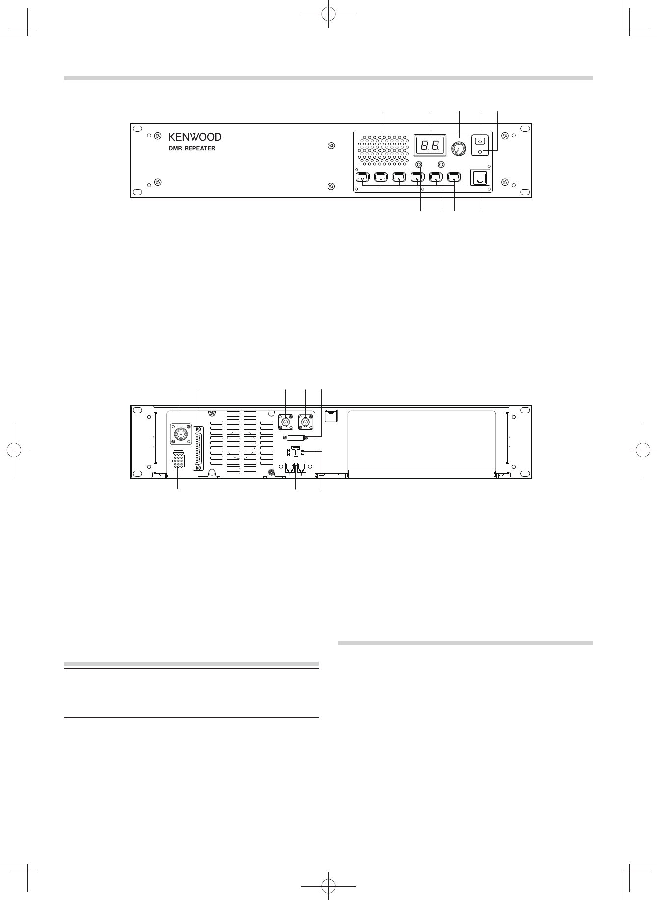
■ Rear Panel
a TX OUT jack
Connect a TX antenna or a duplexer to this receptacle.
b CONTROL I/O jack
Connect a repeater controller or a remote panel to this
DB-25 interface.
c REF IN jack
This jack is currently not used.
d RX IN jack
Connect an RX antenna or a duplexer to this BNC
receptacle.
e FUSE
Insert 15 A blade fuse into this fuse holder.
CONTROLS AND FUNCTIONS
■ Front Panel
f DC 13.6V jack
Connect a 13.6 V DC power supply to this jack.
g N SYNC 1 / 2 jack
This jack is currently not used. Future functions include
connecting another repeater or optional device.
h TEST/SPKR jack
Test input/output jack. Connect an external speaker to this
jack. When using a Built-in speaker, connect the attached
Lead wire with connector (15 pin) to this jack.
TRANSCEIVER OPERATION (Analog mode only)
■ Receive
Adjust the volume to your desired level. You may need to
readjust the volume if you are having interference while
receiving a message from your dispatcher or another member
in your fl eet.
The BUSY indicator lights green while a signal is being
received.
■ Transmit
1 Listen to the channel before transmitting, to make sure it is
not being used.
2 Press the microphone PTT switch, then speak in your
normal speaking voice.
The TX indicator lights red while transmitting.
3 When you fi nish speaking, release the PTT switch.
a Speaker
b CH/STATUS Display
Two 7-segment digits display the channel number, name,
or status.
c VOLUME control
Rotate to adjust the audio.
d POWER switch
e POWER indicator
Lights green when power is supplied to the DC 13.6V jack.
f MIC jack
Connect a microphone to this 8-pin modular jack.
g Programmable Function keys
Press these keys to activate their programmable functions.
h BUSY indicator
Lights green while a signal is being received.
i TX indicator
Lights red while transmitting.
abde
f
g
hi
c
CH/STATUS
VOLUME
BUSY
TX POWER
MIC
abde
fg
c
h
FUSE
N SYNC
DC 13.6V
REF IN RX IN
TX OUT CONTROL
I/O
TEST/SPKR

©
2015
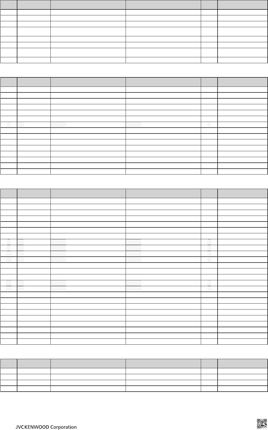
ADDENDUM
Terminal Description
MIC (Modular Jack)
Pin
NO. Pin Name Description SpeciÞ cation I/O Notes
1 NC Not used Not used ̋
2 SB Power Output 13.6 V O
3 GND GND GND ̋
4 PTT PTT Signal/
TXD2 Asynchronous Send Data Input Impedance 22 kǣI/O
5 MICG MIC GND MIC GND ̋
6 MIC MIC Input 600 ǣI
7 HOOK Hook Detection/
RXD2 Asynchronous Receive Data Input Impeadance 100 kǣI
8 NC Not used Not used ̋
TEST/ SPEAKER CONNECTOR
Pin
NO. Pin Name Description SpeciÞ cation I/O Notes
1 SB Power Output 13.6 V O
2 SB Power Output 13.6 V O
3 NC Not used Not used ̋
4 GND GND GND ̋
5 GND GND GND ̋
6 SPG Speaker GND Speaker GND ̋
7 NC Not used Not used ̋
8 RSSI RSSI Signal Output Output Level 0 or 3.3 V O
9 SPI Internal Speaker Input Short with "SPO" I
10 AO1 Open Collector Terminal Allowable current value MAX 200mA O
11 AO2 Open Collector Terminal Allowable current value MAX 200mA O
12 SPO External Speaker Output Output Level 4W (5% Distortion) O
13 AO3 Open Collector Terminal Allowable current value MAX 200mA O
14 AO4 Open Collector Terminal Allowable current value MAX 200mA O
15 AO5 Open Collector Terminal Allowable current value MAX 200mA O
Control I/O (D-SUB 25 Pin) CONNECTOR
Pin
NO. Pin Name Description SpeciÞ cation I/O Notes
1 NC Not used Not used ̋
2 RXD0 Asynchronius Receive Data Conform to RS-232C standard I
3 TXD0 Asynchronius Send Data Conform to RS-232C standard O
4 AI1 Programmable Function Input 1 Input Impedance 47 kǣI
5 AI2 Programmable Function Input 2 Input Impedance 47 kǣI
6 AI3 Programmable Function Input 3 Input Impedance 47 kǣI
7 DG Digital GND Digital GND ̋
8 NC Not used Not used ̋
9 NC Not used Not used ̋
10 NC Not used Not used ̋
11 NC Not used Not used ̋
12 RXG RX Signal GND RX Signal GND ̋
13 SPM Speaker Mute Input Impedance 47 kǣI
14 BER CLK For Bit Error Rate Clock CMOS O
15 NC Not used Not used ̋
16 NC Not used Not used ̋
17 SC Squelch Control Output level 0 or 5 V O
18 BER DAT For Bit Error Rate Data CMOS O
19 TXG TX Signal GND TX Signal GND ̋
20 IO1 Programmable Function I/O 1 Input Impedance 47 kǣ/ Output level 0 or 5 V I/O
21 IO2 Programmable Function I/O 2 Input Impedance 47 kǣ/ Output level 0 or 5 V I/O
22 IO3 Programmable Function I/O 3 Input Impedance 47 kǣ/ Output level 0 or 5 V I/O
23 IO4 Programmable Function I/O 4 Input Impedance 47 kǣ/ Output level 0 or 5 V I/O
24 IO5 Programmable Function I/O 5 Input Impedance 47 kǣ/ Output level 0 or 5 V I/O
25 IO6 Programmable Function I/O 6 Input Impedance 47 kǣ/ Output level 0 or 5 V I/O
N SYNC 1, 2 Connector (There are two connectors)
Pin
NO. Pin Name Description SpeciÞ cation I/O Notes
1 N_SYNC 1_B RS-485 DiŮ rential Signal B Conform to RS-485 I/O Connector#1,2
2 N_SYNC 1_A RS-485 DiŮ rential Signal A Conform to RS-485 I/O Connector#1,2
3 N_SYNC 2_B RS-485 DiŮ rential Signal B Conform to RS-485 I/O Connector#1,2
4 N_SYNC 2_A RS-485 DiŮ rential Signal A Conform to RS-485 I/O Connector#1,2
RX IN RX antenna terminal (BNC Receptacle)
TX OUT TX antenna terminal (N Receptacle)
REF IN Reference CLK input treminal (BNC Receptacle)
B5K-0230-00
© 2015
7 NC Not used Not used
7 NC Not used Not used
7 NC Not used Not used
7 NC Not used Not used
7 NC Not used Not used
7 NC Not used Not used
7 NC Not used Not used
̋
8 NC Not used Not used
8 NC Not used Not used
8 NC Not used Not used
8 NC Not used Not used
8 NC Not used Not used
8 NC Not used Not used
8 NC Not used Not used
̋
9 NC Not used Not used
9 NC Not used Not used
9 NC Not used Not used
9 NC Not used Not used
9 NC Not used Not used
9 NC Not used Not used
9 NC Not used Not used
̋
10 NC Not used Not used
10 NC Not used Not used
10 NC Not used Not used
10 NC Not used Not used
10 NC Not used Not used
10 NC Not used Not used
10 NC Not used Not used
̋
11 NC Not used Not used
11 NC Not used Not used
11 NC Not used Not used
11 NC Not used Not used
11 NC Not used Not used
11 NC Not used Not used
11 NC Not used Not used
̋
15 NC Not used Not used
15 NC Not used Not used
15 NC Not used Not used
15 NC Not used Not used
15 NC Not used Not used
15 NC Not used Not used
15 NC Not used Not used
̋
16 NC Not used Not used
16 NC Not used Not used
16 NC Not used Not used
16 NC Not used Not used
16 NC Not used Not used
16 NC Not used Not used
16 NC Not used Not used
̋
MANDATORY SAFETY INSTRUCTIONS TO INSTALLERS AND USERS
• Use only manufacturer or dealer supplied antenna.
• Antenna Minimum Safe Distance: 120 cm (4 feet), 50% duty Cycle.
• Antenna Gain: 0 dBd referenced to a dipole.
The Federal Communications Commission has adopted a safety standard for
human exposure to RF (Radio Frequency) energy which is below the OSHA
(Occupational Safety and Health Act) limits.
•
Antenna Mounting: The antenna supplied by the manufacturer or
radio dealer must not be mounted at a location such that during radio
transmission, any person or persons can come closer than the above
indicated minimum safe distance to the antenna, i.e. 120 cm (4 feet) ,
50% duty Cycle.
• To comply with current FCC RF Exposure limits, the antenna must be
installed at or exceeding the minimum safe distance shown above, and in
accordance with the requirements of the antenna manufacturer or supplier.
• Vehicle installation: The antenna can be mounted at the center of a vehicle
metal roof or trunk lid, if the minimum safe distance is observed.
• Base Station Installation: The antenna should be fi xed-mounted on
an outdoor permanent structure. RF Exposure compliance must be
addressed at the time of installation.
Antenna substitution: Do not substitute any antenna for the one supplied or
recommended by the manufacturer or radio dealer.
You may be exposing person or persons to excess radio frequency radiation.
You may contact your radio dealer or the manufacturer for further instructions.
Maintain a separation distance from the antenna to person(s) of at least
120 cm (4 feet) , 50% duty Cycle.
You, as the qualifi ed end-user of this radio device must control the exposure
conditions of bystanders to ensure the minimum separation distance (above)
is maintained between the antenna and nearby persons for satisfying RF
Exposure compliance. The operation of this transmitter must satisfy the
requirements of Occupational/Controlled Exposure Environment, for work-
related use, transmit only when person(s) are at least the minimum distance
from the properly installed, externally mounted antenna. Transmit only when
people outside the vehicle are at least the recommended minimum lateral
distance away from the antenna/vehicle.
B59-2353-10