JVC KENWOOD 512000 Scanning Receiver User Manual 1
JVC KENWOOD Corporation Scanning Receiver Users Manual 1
UserManual.wiki
>
JVC KENWOOD
>
512000 User Manual
>
Users Manual 1
Contents
1.
Users Manual 1
2.
Users Manual 2
3.
Users Manual 3
4.
Users Manual 4
Users Manual 1
Navigation menu
Upload a User Manual
Namespaces
Wiki Guide
HTML
PDF
Info
Views
User Manual
Discussion / Help
Navigation
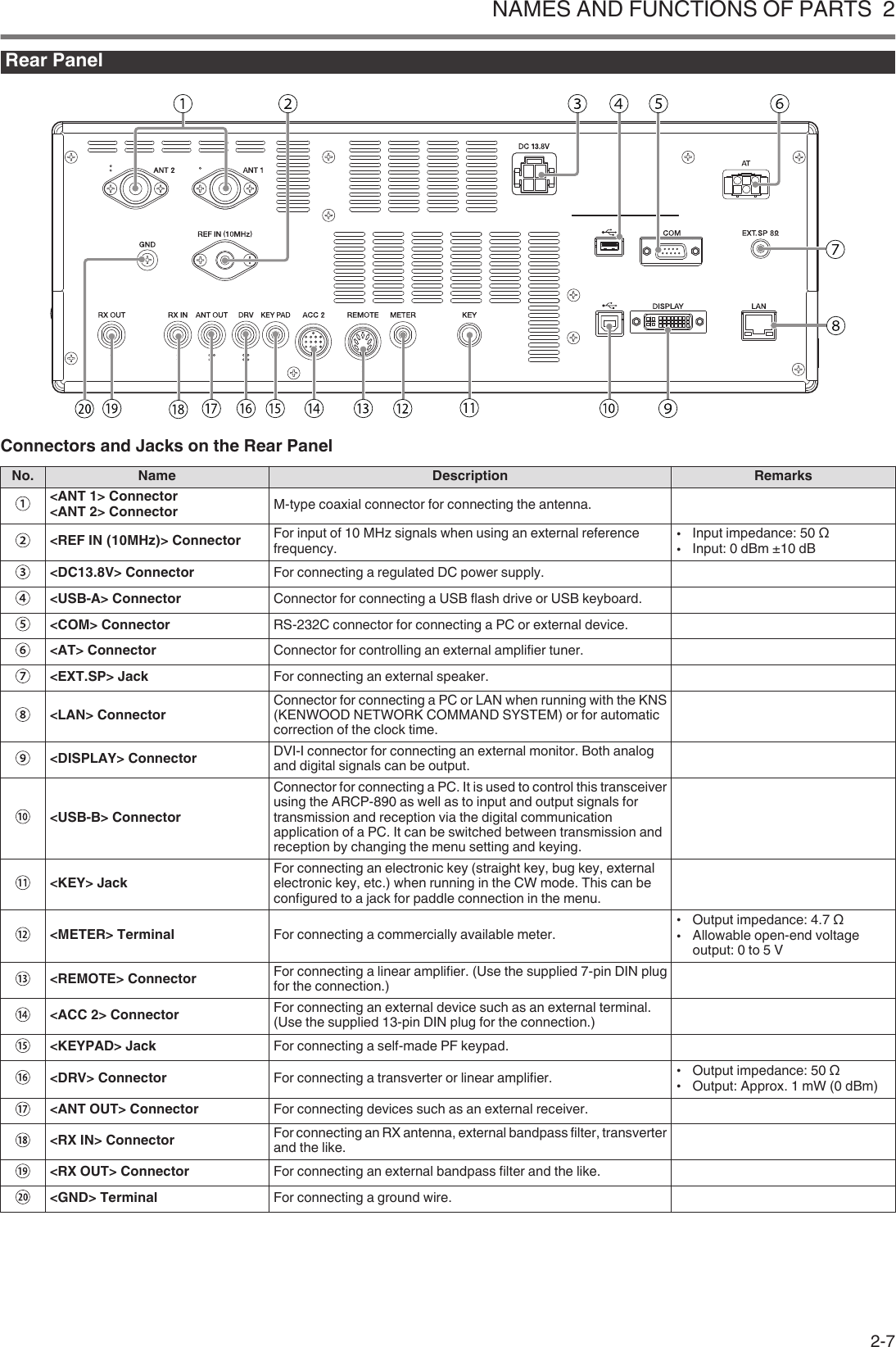
![Thank YouThank you for choosing this KENWOOD TS-890S transceiver.FEATURES●A high-end and practical transceiver with basic receptionperformance that exceeds its class, with multiple functions andwith a feel of TS-990●Incorporates a 7" TFT color display for comfortable centralizedcontrol of operations using various information: auto scrollmode, filter scope, TX bar meter, etc.●Top-class basic reception performanceProvides third-order intermodulation DR: 110 dB, RMDR: 112dB and BDR**: 150 dB (Measurement example at 2 kHzdetuning: RX frequency 14.2 MHz, MODE CW, BW 500 Hz,PRE AMP OFF)*RMDR (Reciprocal Mixing Dynamic Range), **BDR (BlockingDynamic Range)●HF band +50 MHz●100 W heavy duty output power (50 W for TS-890D)●Built-in automatic antenna tuner (relay system, high speedmatching)●SSB, CW, FSK (RTTY), PSK31 (BPSK/QPSK), PSK63 (BPSK),AM, FM●Capable of FSK, PSK31/63 as well as CW decoding/encoding●Equipped with two 32-bit floating-point arithmetic DSPs fortransmission and reception and scope display●Equipped with LAN, USB and COM ports●External display connection (via DVI-I connector)●Capable of remote control operation (direct IP connection)without using a host PC. Radio Control Program (ARCP-890)and Radio Host Program (ARHP-890) are also provided free asbefore●Supports USB audio. The speaker and the microphone of a PCcan be used during the USB audio operation by using ARUA-10(Freeware)Supplied AccessoriesThe following accessories are supplied with the transceiver. Aftercarefully unpacking the transceiver, identify the accessories listedin the table.Item QuantityK-type E-typeDC power cable 1 17-pin DIN plug(For REMOTE connector) 1 113-pin DIN plug(For ACC2 connector) 1 1Fuse 4 A 1 1Fuse 25 A 1 1Instruction ManualEnglish 1 1French 1 1Spanish – 1Italian – 1German – 1Dutch – 1Schematic diagram 3 3Warranty Card 1 1●We recommend you keep the box and packing materialsin case you need to repack the transceiver in the future.●Do not put the plastic bag used for packing of thisequipment on the place which reaches a small child’shand. It will become a cause of suffocation if it wearsflatly.Market CodesK-type: :The AmericasE-type: :EuropeThe market code is shown on the carton box.Refer to the specifications for information on the availableoperating frequencies.Copyrights for This Manual●JVC KENWOOD Corporation shall own all copyrights and otherintellectual properties for the product and the software and forall manuals and documents attached to the product and thesoftware.●A user is required to obtain approval from JVC KENWOODcorporation, in writing, prior to redistributing this document ona personal web page or via packet communication.●A user is prohibited from assigning, renting, leasing or resellingthe document.●JVC KENWOOD Corporation does not warrant that quality andfunctions described in this manual comply with each user’spurpose of use and, unless specifically described in thismanual, JVC KENWOOD Corporation shall be free from anyresponsibility for any defects and indemnities for any damagesor losses.Software CopyrightsThe title to and ownership of copyrights for software, including butnot limited to the firmware that may be distributed individually, tobe embedded in KENWOOD product memories, are reserved forJVC KENWOOD Corporation.Any modifying, reverse engineering, copying, reproducing ordisclosing on an Internet website of the software is strictlyprohibited.A user is required to obtain approval from JVC KENWOODcorporation, in writing, prior to redistributing this manual on apersonal web page or via packet communication.Furthermore, any reselling, assigning or transferring of thesoftware is also strictly prohibited without embedding the softwarein KENWOOD product memories.Software License AgreementSoftware License Agreement contains the terms and conditions ofuse of the software embedded in or used with the transceiver. Auser is entitled to use the software subject to the acceptance andagreement of this Software License Agreement by the user. Also,this Software License Agreement stipulates the terms andconditions of use of this software embedded in or used with thetransceiver, and a user has the right to use the transceiver with thesoftware embedded subject to the applicable laws andregulations, the description and defined in this manual and thewarranty card.The Software License Agreement can be displayed in the menubelow. (Refer to Chapter 3 for operation of menu.)Advanced menu [24] “Software License Agreement”BEFORE USING BEFORE USINGi](https://usermanual.wiki/JVC-KENWOOD/512000.Users-Manual-1/User-Guide-3944945-Page-3.png)
![Important Notices Concerning the SoftwareLicense AgreementThe software embedded in this transceiver consists of a multiplenumber of and individual software components. Title to andownership of copyrights for each software component is reservedfor JVC KENWOOD Corporation and the respective bona fideholder.This product employs the software component in accordance withthe End User License Agreement (hereinafter referred to as the“EULA”) stipulated by JVC KENWOOD Corporation and/or therespective bona fide holder.There is free software stipulated and governed by the “EULA”, andthis, a distribution condition of the software component in theexecutable format under the terms and conditions contained in theGNU General Public License or Lesser General Public License(hereinafter referred to as the “GPL/LGPL”), requires to make thesource code for the relevant software components available.Access the URL below for details of the software componentstipulated in the “GPL/LPGL”.http://www2.jvckenwood.com/gpl/index.htmlImportant notice about software can be displayed in the menubelow. (Refer to Chapter 3 for operation of menu.)Advanced menu [25] “Important Notices concerning Free OpenSource”About the GPL/ LPGL LicenseThe GPL / LGPL license agreement can be displayed in the menubelow. (Refer to Chapter 3 for operation of menu.)Advanced menu [26] “About Various Software LicenseAgreements”This product includes “Ubiquitous QuickBoot™” technologydeveloped by Ubiquitous Corp.Ubiquitous QuickBoot™ is a trademark of Ubiquitous Corp.Copyright © 2018 Ubiquitous Corp. All rights reserved..Copyrights for Recorded AudioThe broadcast content recorded in this transceiver may not bereused, except for the personal use, without prior consent of theright holder under the copyright laws.TrademarksKENWOOD is a registered trade mark of JVC KENWOODCorporation.All other product names referenced herein are trademarks orregistered trademarks of their respective manufacturers. Markssuch as ™ and Ⓡ are omitted in the text of body.Indemnity●JVC KENWOOD Corporation takes all appropriate measuresto ensure all descriptions in this manual are accurate; however,this manual may still contain typographical errors (“typos”) andexpressions that are misleading. JVC KENWOOD Corporationis entirely free from any responsibilities arising from any lossesor damages caused by such typos or expressions.JVC KENWOOD Corporation has the right to change orimprove the product specifications, etc., described in thismanual without prior notice.JVC KENWOOD Corporation is entirely free from anyresponsibilities for any losses or damages caused by suchchanges and improvements.●JVC KENWOOD Corporation is entirely free from anyresponsibilities for any failures, damages or losses arising from,or in connection with, use of the transceiver with or connectedto any external equipment.●JVC KENWOOD Corporation does not warrant that the qualityand functions described in this manual comply with yourpurpose of use and, unless specifically described in thismanual, JVC KENWOOD Corporation shall be free from anyresponsibilities for any defects and indemnities for anydamages or losses. Selection and installation of any externalequipment shall be done at your own risk. You are fullyresponsible for the use and effects of external equipment.●JVC KENWOOD Corporation shall be free from anyresponsibilities for any incidental losses or damages, such asmissing communications or call opportunities caused by afailure or performance error of the transceiver.Your Queries about External Devices or PCConnected to the TransceiverJVC KENWOOD Corporation are pleased to answer, within thescope of corporate efforts we can provide, your queries about youroperation of this transceiver. Please bear in mind that we cannotanswer any and all technical questions regarding methods ofconnection to, configuration for and operation of any externaldevice and PC beyond our knowledge.Handling Your Important DataThere is always a risk of losing your important data due totransceiver failure, occurrence of an unforeseen contingency,erroneous operation or faulty behavior of the transceiver. The data,such as the operating information, recorded audio, messages,configuration data, logs, etc., must be backed up as necessary byyourself and stored in the external storage device such as a USBflash drive. BEFORE USINGii](https://usermanual.wiki/JVC-KENWOOD/512000.Users-Manual-1/User-Guide-3944945-Page-4.png)
![BEFORE USING CONTENTS1 INSTALLATION AND CONNECTIONInstallation .......................................................................................... 1-1Antenna Installation and Connection .............................................. 1-1Ground Connection ......................................................................... 1-1Installation of Lightning Arrestors .................................................... 1-1Connection of Regulated DC Power Supply ................................... 1-1Using the Auxiliary Support ............................................................. 1-1Torque Adjustment with Tuning Control .............................................. 1-2Connection of Accessories (Front Panel) ........................................... 1-2Connection of Accessories (Rear Panel) ............................................ 1-3Connection with Data Communication Equipment .............................. 1-4PC Connection ................................................................................ 1-4TNC Connection ............................................................................. 1-4Terminal Descriptions ......................................................................... 1-52 NAMES AND FUNCTIONS OF PARTSFront Panel ......................................................................................... 2-1Panel Key Behavior ......................................................................... 2-1List of Function Key Behaviors (Standard Mode Screen) ................ 2-4Rear Panel .......................................................................................... 2-7Microphone (Optional) ........................................................................ 2-8Screen ................................................................................................ 2-93 MENUMenu Operation .................................................................................. 3-1Calling Up a Menu ........................................................................... 3-1Calling Up a Sub-Menu ................................................................... 3-1Advanced Menu .......................................................................... 3-1Common Menu Screen Operations ................................................. 3-2Exiting the Menu .......................................................................... 3-2Switching between the CONFIG A and CONFIG B OperatingEnvironments .................................................................................. 3-2Menu Items ..................................................................................... 3-34 BASIC OPERATIONSTurning ON/OFF the Power ................................................................ 4-1Screen Display Settings ..................................................................... 4-1Changing the Background Color ..................................................... 4-1Changing the Type of Function Key Display ................................... 4-1Changing the Frequency Display Font Type ................................... 4-1Dimmer ............................................................................................... 4-2Switching the Brightness Level ....................................................... 4-2Adjusting the Dimmer Level ............................................................ 4-2Adjusting AF Gain ............................................................................... 4-2Adjusting RF Gain ............................................................................... 4-2Adjusting the Squelch Level ............................................................... 4-2Selecting VFO A/ B ............................................................................. 4-2Selecting an Operating Band .............................................................. 4-3Changing the Number of Band Memories ....................................... 4-3Selecting an Operating Mode ............................................................. 4-4SSB (LSB-USB) Mode .................................................................... 4-4CW/ CW-R Mode ............................................................................ 4-4FSK/ FSK-R/ PSK/ PSK-R Mode .................................................... 4-4FM/ AM Mode ................................................................................. 4-4DATA Mode .................................................................................... 4-4Auto Mode .......................................................................................... 4-4Turning ON/OFF Auto Mode ........................................................... 4-4Configuring Auto Mode Frequency Points ....................................... 4-4Adjustment of Frequencies ................................................................. 4-5Adjustment Using the Tuning Control .............................................. 4-5Adjustment Using the Microphone Key ........................................... 4-5FINE Tuning .................................................................................... 4-5Configuring the Number of Steps per Revolution of the Tuning Control......................................................................................................... 4-5Configuring the Fast Forward Rate of the Tuning Control ............... 4-5Configuring the Sensitivity for Starting the Fast Forward Operation 4-5Frequency Adjustment Using the [MULTI/CH] Control .................... 4-6Rounding the Frequency ............................................................. 4-6Configuring the Frequency Step Size of the [MULTI/CH] Control 4-6Switching the AM Broadcast Frequency in 9 kHz Steps .............. 4-6Adjusting Frequency in MHz Steps ................................................. 4-6Configuring the Frequency Step Size in MHz .............................. 4-6Direct Input of Frequency Value ...................................................... 4-6Frequency Input History .................................................................. 4-7Frequency Lock .............................................................................. 4-7Lock Target ................................................................................. 4-7Transmission ...................................................................................... 4-7Audio Transmission ........................................................................ 4-7CW Transmission ............................................................................ 4-7Adjusting Microphone Gain ............................................................. 4-7Adjusting TX Output Power ............................................................. 4-8Fine Adjustment of TX Output Power .............................................. 4-8TX Output Power Limiter .................................................................... 4-8Turning ON/OFF TX Output Power Limiter ...................................... 4-8Configuring the TX Output Power Limiter ........................................ 4-8Meter .................................................................................................. 4-9Changing the Meter Type ................................................................ 4-9Changing the Meter Type from the Menu .................................... 4-9Changing the Meter Type via Touchscreen Operation ................ 4-9Switching between TX Meters ........................................................ 4-9FM Mode S-meter Sensitivity .......................................................... 4-9Analog Meter Response ................................................................. 4-9Meter with Peak Hold ...................................................................... 4-9S Meter Scale ................................................................................. 4-9TX Meter (Digital) .......................................................................... 4-10Switching the Antenna ...................................................................... 4-10RX Antenna ...................................................................................... 4-10Drive Output (DRV) ........................................................................... 4-10Turning ON/OFF Drive Output ...................................................... 4-10Adjusting the Drive Output Level ............................................... 4-10Built-in Antenna Tuner ...................................................................... 4-11Impedance Matching with the Antenna ......................................... 4-11Preset ........................................................................................... 4-11Holding Transmission at the End of Antenna Tuning .................... 4-11Switching Antenna Tuner Behavior during Reception ................... 4-12Configuring the Built-in Antenna Tuner Behavior for Each Band ... 4-12Connecting the External Antenna Tuner AT-300 ........................... 4-125 COMMUNICATING AIDSSplit Operation .................................................................................... 5-1Direct Input of Frequency Difference Specified by DX Station ........ 5-1Turning the Tuning Control to Search for a TX Frequency .............. 5-1⊿F Display ...................................................................................... 5-1Changing the split frequency using the [RIT/XIT] control ................. 5-1Configuring the Band Direct Key during Split Operation ................. 5-1TF-SET (Setting the TX Frequency) ................................................ 5-2AGC .................................................................................................... 5-2Switching the AGC Time Constant .................................................. 5-2Adjusting the AGC Time Constant Preset Value ............................. 5-2AGC OFF ........................................................................................ 5-3AGC Quick Recovery ...................................................................... 5-3RX Equalizer ....................................................................................... 5-4Turning ON/OFF RX Equalizer ........................................................ 5-4Selecting an RX Equalizer Characteristic ........................................ 5-4Adjusting the Equalizer Characteristics ........................................... 5-4Copying Equalizer Data .................................................................. 5-4Saving Equalizer Data ..................................................................... 5-5Reading Equalizer Data .................................................................. 5-5CONTENTS CONTENTSv](https://usermanual.wiki/JVC-KENWOOD/512000.Users-Manual-1/User-Guide-3944945-Page-7.png)

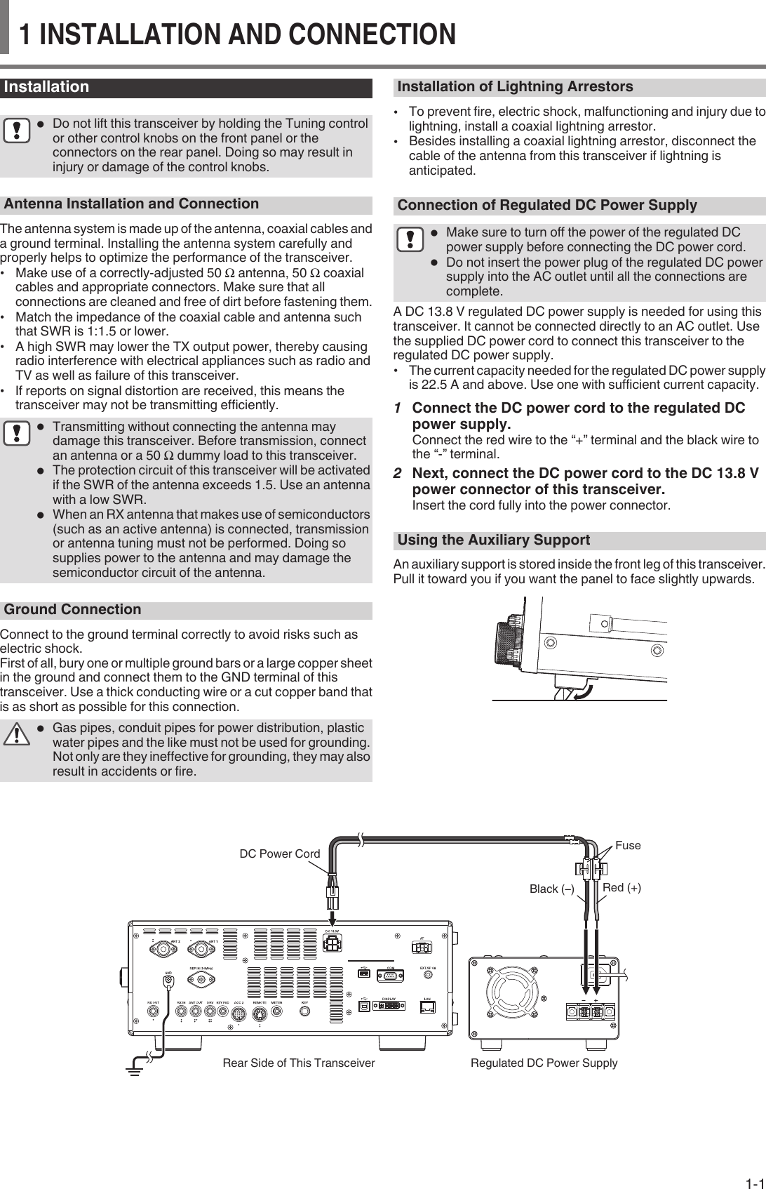
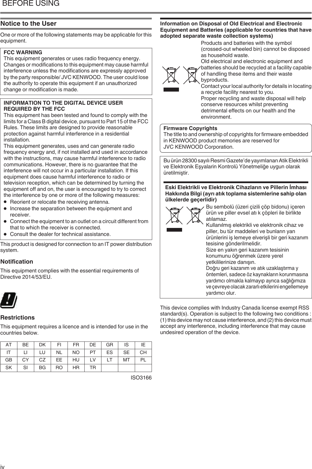
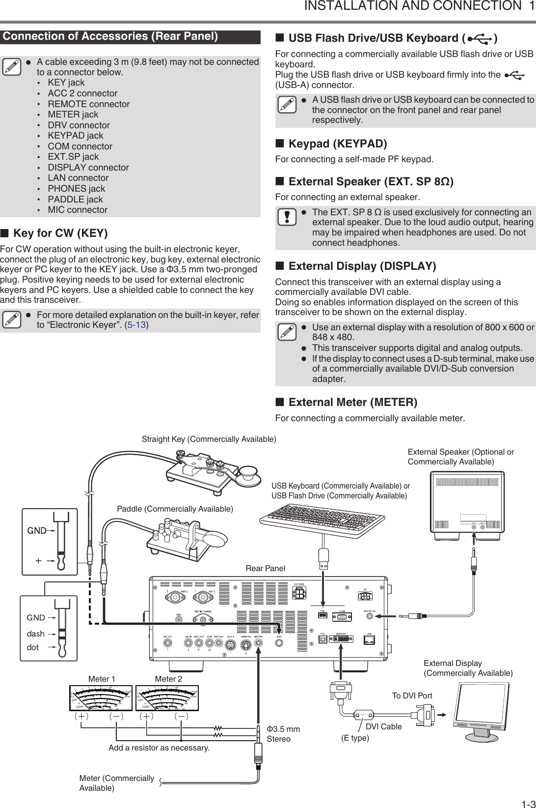
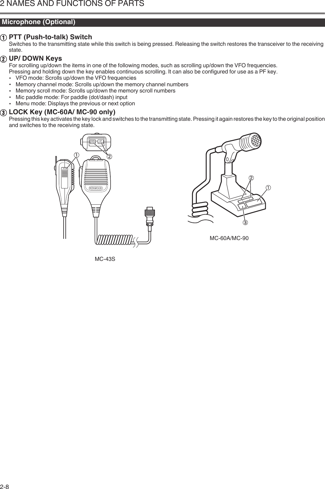
![Torque Adjustment with Tuning ControlThe Tuning control allows the rotational torque (weight) to beadjusted according to the user’s preference. With the ring at thebase of the Tuning control fixed, turning the Tuning control to theright increases the rotational torque, while turning to the leftdecreases it..RingConnection of Accessories (Front Panel)■Headphones (PHONES)Monaural and stereo headphones (4 to 32 Ω, standard: 8 Ω/plug:Φ6.3 mm) can be used with this transceiver.When headphones are connected, sound will not be output fromthe built-in speakers (or optional external speakers). The followingoptional headphones are compatible with this transceiver.●HS-5 ●HS-6●The volume may be louder for headphones with a higherimpedance.●The audio output is monaural even when stereoheadphones are connected.■Paddle (PADDLE)For CW operation using the built-in electronic keyer, connect akeyer paddle to the PADDLE jack. A Φ6.3 mm three-pronged plugis used for the paddle. Also, a straight key can be connected to thePADDLE jack. In this case, change the setting of Menu [5-00] to“Straight Key”. (Refer to Chapter 3 for details on menu operation.)■USB Flash Drive/USB Keyboard ( )For connecting a commercially available USB flash drive or USBkeyboard.Plug the USB flash drive or USB keyboard firmly into the (USB-A)connector.●Do not remove the USB flash drive while reading orwriting files or while the USB flash drive is beingaccessed by this transceiver. Also, do not turn off thepower of this transceiver.●Always remove the USB flash drive after ensuring thatthis can be done safely to prevent data in the USB flashdrive from being damaged. (USB/File ManagementMenu “Safe Removal of USB Flash Drive”)●A USB flash drive or USB keyboard can be connected tothe connector on the front panel and rear panelrespectively.■Microphone (MIC)Microphones with an impedance of 250 Ω to 600 Ω can be used.Insert the microphone plug fully into the MIC connector of thistransceiver and tighten it firmly using the fastening ring.The following microphones (sold separately) are compatible withthis transceiver.●MC-43S ● MC-60A ● MC-90 ●MC-47The following microphones are not compatible with this transceiver.●MC-44 ●MC-44DM ●MC-45 ●MC-45DM.Microphone Connector (View from Front Panel)8V (10mA max)NCGND (MIC)GND (STBY)UPDOWNPTTMICMicrophone (Optional or Commercially Available)USB Flash Drive (Commercially Available) or USB Keyboard (Commercially Available)Front PanelPaddle (Commercially Available)Straight Key (Commercially Available)Headphones (Optional or Commercially Available)1 INSTALLATION AND CONNECTION1-2](https://usermanual.wiki/JVC-KENWOOD/512000.Users-Manual-1/User-Guide-3944945-Page-14.png)
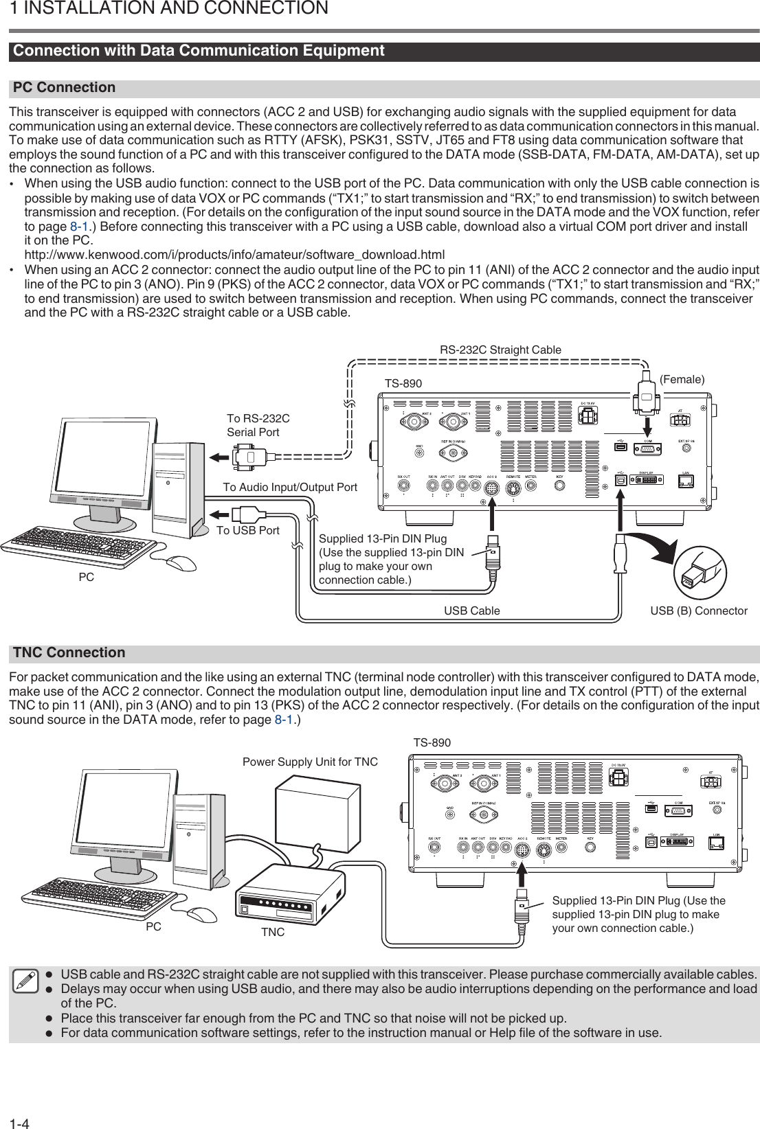
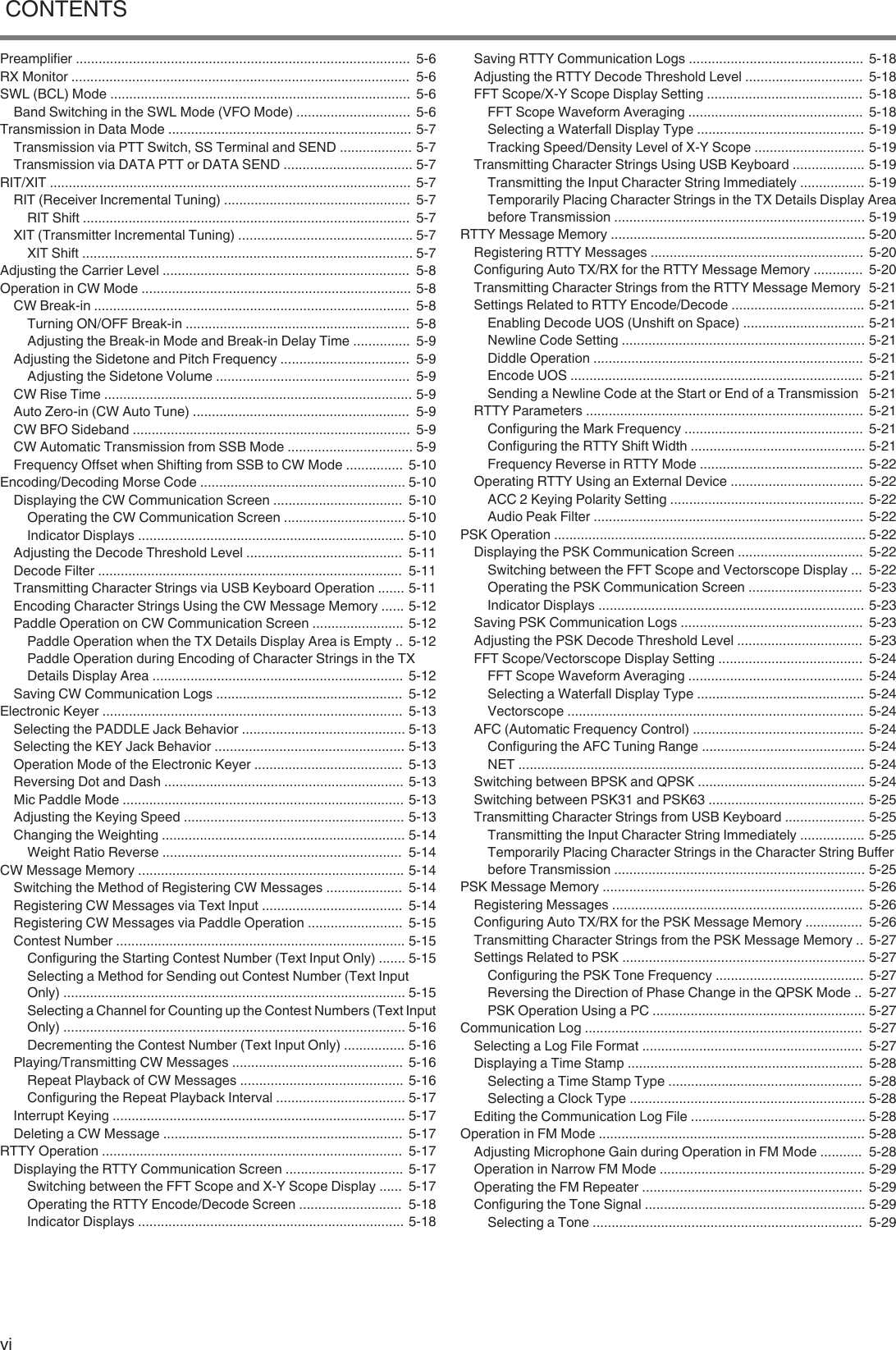
![.ACC 2 ConnectorPin No. Pin Name Function Input/Output— NC No connection —2 RTTY RTTY control terminal (FSK key input) I3 ANOAudio output•Connect to the audio input of the TNC, MCP or PC (or PC connection interface).•The audio output level is independent of the AF volume control knob on the front panel.•The audio output level can be adjusted in Menu [7-09]. Adjust it to an appropriate level.•When the audio output level is configured to the default value of “50” in Menu [7-09], the peak-to-peak voltage is approximately 0.5 V p-p in the case of standard modulation signals. Altering theaudio output level between “0” and “100” changes the peak-to-peak voltage level betweenapproximately 0 Vp-p and 1.2 Vp-p. (Impedance 10 kΩ)O4 GND Signal ground —5 PSQSquelch control output•Connect to the squelch input of the TNC, MCP or PC connection interface.•When squelch is open: Low impedance•When squelch is closed: High impedanceO6 MET 1 Meter level output 1 O7 NC No connection —8 GND Signal ground —9 PKSPTT input for data communication (DATA SEND)•Connect to the PTT output of the TNC, MCP or PC connection interface.•Signal can be transmitted by connecting the PKS terminal to GND.•The PKS terminal mutes unnecessary modulation input signals during transmission.“Configuration of the Input Path of TX Audio”I10 MET2 Meter level output 2 O11 ANIAudio input for data communication•Connect to the audio output of the TNC, MCP or PC (or PC connection interface).•The audio input level is independent of MIC GAIN on the front panel.•The audio input level can be adjusted in Menu [7-07].•Standard modulation can be obtained with an input of approximately 10 mVrms in the defaultsetting of “50” in Menu [7-09]. Altering the audio input level between “0” and “100” changes thestandard modulation input level between approximately “almost no modulation” and approx. 1mVrms. (Impedance 10 kΩ)I12 GND Signal ground —13 SSPTT input•This is the same terminal as pin 2 (SS terminal) of the MIC connector on the front panel and pin 3(SS terminal) of the REMOTE connector.•It has the same behavior as pressing [SEND] on the front panel.•Signal can be transmitted by connecting the SS terminal to GND.•The SS terminal mutes unnecessary modulation input signals during transmission. “Configurationof the Input Path of TX Audio”I1 INSTALLATION AND CONNECTION1-6](https://usermanual.wiki/JVC-KENWOOD/512000.Users-Manual-1/User-Guide-3944945-Page-18.png)

![Front Panel.Panel Key Behavior Key Behavior Refer to.[ ]Press Turns on the power.4-1Press andhold Turns off the power..[PF A]PressActivates the registered function. 16-2Press andhold[VOX]Press Turns ON/OFF the VOX function. 8-1Press andhold Displays the VOX configuration screen. 8-2.[SEND] Press Starts/ends transmission. 4-7[AT]Press Turns ON/OFF the antenna tuner.4-11Press andhold Starts antenna tuning..[ESC] Press Exits the configuration screen. –.[F1] to [F7](HorizontallyArrayed F)Activates the function according to the key guide at the bottom of the screen.(Henceforth represented as F1 [XXX] to F7 [XXX] in this manual.)Refer to “List of Function Key Behaviors (Standard Mode Screen)” for functions of the F key on the normalscreen.2-4.[SCP]Press Displays the bandscope.Switches the scope screen. 7-17-6Press andhold Displays the audio scope.Switches between bandscope and audio scope.[MHz] Press Turns ON/OFF the MHz step function. 4-6.[LSB/USB] Press Switches between the LSB and USB modes. 4-4[CW/CW-R] Press Switches between the CW and CW-R modes. 4-4[FSK/PSK]Press Switches between the FSK and PSK modes.4-4Press andhold Switches between reverse and normal in the FSK/PSK mode.[FM/AM]Press Switches between the FM and AM modes.4-4Press andhold Switches between FM narrow and FM normal.[DATA]Press Switches the DATA mode. 4-4Press andhold Displays the input source configuration screen for the TX audio. 8-1NAMES AND FUNCTIONS OF PARTS 22 NAMES AND FUNCTIONS OF PARTS2-1](https://usermanual.wiki/JVC-KENWOOD/512000.Users-Manual-1/User-Guide-3944945-Page-21.png)
![Key Behavior Refer to.[CW T.] Press Activates the CW auto tune function. 5-9[IF FIL]Press Switches between receiver (RX) filters A, B and C. 6-1Press andhold Displays the RX Filter screen. 6-2[FIL CLR] Press Restores the passband of the RX filter that has been changed to the preset value. 6-4[FINE] Press Turns ON/OFF the FINE-tuning function. 4-5.[ ] to [ ] (VerticallyArrayed F)Activates the function according to the key guide on the right side of the screen. (Henceforth representedas F [XXX] in this manual.)Refer to “List of Function Key Behaviors (Standard Mode Screen)” for functions of the F key on the normalscreen.2-4.[0 (50)] to [9 (28)] Press For selecting a frequency band and switching band memory. 4-3[CLR] Press Cancels the direct frequency input mode. –[ENT] Press Turns on the direct frequency input mode. 4-6.[RX ANT]Press Turns ON/OFF the RX antenna. 4-10Press andhold Turns ON/OFF the antenna output function for the external receiver. 16-15[DRV] Press Turns ON/OFF the drive output function. 4-10[GENE]Press For selecting a general coverage band. 4-3Press andhold Turns ON/OFF the transverter function. 16-15.[ ]Press Starts, pauses or resumes manual recording. 12-3Press andhold Saves the constantly recorded audio file. 12-3[]Press Stops audio recording or playback. 12-4[ ] Press Starts, pauses or resumes playback..[A/B]Press Switches between VFO A and VFO B. 4-2Press andhold Aligns the frequency and mode of VFO A and VFO B. 5-1.[PF B]PressActivates the registered function. 16-2Press andhold[PF C]PressActivates the registered function. 16-2Press andhold.[SPLIT]Press Turns ON/OFF the split mode. 5-1Press andhold Starts configuration of the frequency for split operation. 5-1[LOCK] Press Turns ON/OFF the frequency lock function. 4-7[M/V]Press Switches between the memory channel and VFO mode. 9-2Press andhold Copies the memory channel data and quick memory channel data to VFO. 9-32 NAMES AND FUNCTIONS OF PARTS2-2](https://usermanual.wiki/JVC-KENWOOD/512000.Users-Manual-1/User-Guide-3944945-Page-22.png)
![Key Behavior Refer to.[ M.IN] PressDisplays the memory channel list screen. 9-1Registers a memory channel. 9-1Switches the menu mode item. 3-1[<Q-M.IN] Press Registers a quick memory channel. 9-5Switches the menu mode item. 3-1[Q-MR>]Press Calls up a quick memory channel. 9-5Switches the menu mode item. 3-1Press andhold Deletes all quick memory channels. 9-5[ ] Press Switches the menu mode item. 3-1.[MENU] Press Turns ON/OFF the menu mode. 3-1[TF-SET] Press Turns ON/OFF TF-SET. (ON while it is being pressed.) 5-2.[MONI]Press Turns ON/OFF the TX monitor function. 8-3Press andhold Displays the TX monitor level configuration screen. 8-3[CAR] Press Displays the carrier level configuration screen. 5-8.[AGC]Press Switches the AGC time constant [FAST, MID, SLOW]. 5-2Press andhold Displays the AGC configuration screen. 5-2[NR]Press Switches the mode of the noise reduction function [OFF/NR1/NR2]. 6-7Press andhold Displays the NR1 configuration screen. (When Noise Reduction 1 is ON)Displays the NR2 configuration screen. (When Noise Reduction 2 is ON) 6-7[NB1]Press Turns ON/OFF the Noise Blanker 1. 6-5Press andhold Displays the NB1 configuration screen. 6-5[NB2]Press Turns ON/OFF the Noise Blanker 2. 6-5Press andhold Displays the NB2 configuration screen. 6-6.[BC] Press Switches the mode of the beat canceler function [OFF/BC1/BC2]. 6-8[NCH]Press Turns ON/OFF the notch filter. 6-6Press andhold Switches the bandwidth of the notch filter [Normal, Middle, Wide]. 6-7.[RIT]Press Turns ON/OFF the RIT function. 5-7Press andhold Shifts the RX frequency via RIT. 5-7[XIT]Press Turns ON/OFF the XIT function. 5-7Press andhold Shifts the TX frequency via XIT. 5-7[CL] Press Clears the RIT or RIT/XIT frequency. 5-7NAMES AND FUNCTIONS OF PARTS 22-3](https://usermanual.wiki/JVC-KENWOOD/512000.Users-Manual-1/User-Guide-3944945-Page-23.png)
![List of Function Key Behaviors (Standard Mode Screen)Function Keys (Vertically Arrayed) Key Guide Behavior Refer toF[ANT/PRE]Press Switches the preamplifier. (OFF/ PRE 1/ PRE 2) 5-6Press andhold Switches between “ANT 1” and “ANT 2”. 4-10[ATT]Press Switches the attenuation level of the attenuator. (OFF/ 6 dB/ 12 dB/ 18 dB) 6-1Press andhold Switches in the reverse order. 6-1[RX EQ]Press Turns ON/OFF the RX equalizer. 5-4Press andhold Displays the RX equalizer configuration screen. 5-4[TX EQ]Press Turns ON/OFF the TX equalizer. 8-5Press andhold Displays the TX equalizer configuration screen. 8-5[MAX-Po]Press Turns ON/OFF the TX output power limiter. 4-8Press andhold Displays the TX output power limiter configuration screen. 4-8[METER] Press Switches the meter display. 4-8[PROC]Press Turns ON/OFF the speech processor. 8-3Press andhold Displays the Speech Processor configuration screen. 8-3Function Keys (Horizontally Arrayed) Key Guide Behavior Refer toF1 [RX PLAY] Press Displays the audio recording file screen. 12-4F2 [TX MSG] Press Displays the voice message screen. (Displayed in the SSB, AM and FM modes.) 12-1[KEYER] Press Displays the CW message screen. (Displayed in the CW mode.) 5-14F3 [DECODE] Press Displays the communication screen. (Displayed in the CW, FSK and PSK modes.) 5-105-225-22F4 [TONE]Press Switches in the sequence of: “TONE” → “CTCSS” → “CROSS TONE”. (Displayed in the FM mode.) 5-285-305-30Press andhold Displays the TONE frequency, CTCSS frequency or cross tone configuration screen.F5 [SCAN]Press Starts/stops scanning. 10-110-3Press andholdDisplays the VFO/Program Scan segment screen. (Displayed in the VFO mode.) 10-1Displays the memory scan group screen. (Displayed in the memory channel mode.) 10-3F6 [M VFO] Press Shifts the memory.(Displayed in the memory channel and quick memory channel modes.) 9-39-6F7 [M.LIST] Press Displays the memory channel list. 9-12 NAMES AND FUNCTIONS OF PARTS2-4](https://usermanual.wiki/JVC-KENWOOD/512000.Users-Manual-1/User-Guide-3944945-Page-24.png)
![.List of Control Knob Behaviors Control Behavior Refer to.Tuning Aligns the TX and RX frequencies. 4-5.[MULTI/CH]Switches the frequency at a fast speed. (Available in the VFO mode.) 4-5Switches the channel number. (Available in the memory channel and quick memory channelmodes.) 9-2Switches the item to configure or configured value. (Available when a configuration screen isdisplayed.) 3-1.[RIT/XIT] Changes the RIT/XIT frequency. 5-7.[KEY] Adjusts the keying speed. 5-13[DELAY] Adjusts the break-in delay time. (When the TX mode is configured to CW.) 5-8Adjusts the VOX delay time. (When the TX mode is configured to SSB, FM or AM.) 8-2.[MIC/PITCH]Adjusts the microphone gain. (When the TX mode is configured to SSB or AM.) 4-7Adjusts the sidetone/pitch frequency. (When the TX mode is configured to CW.) 5-9Adjusts the speech processor output level. (When the speech processor is ON.) 8-3[POWER] Changes the TX output power level. 4-7.[HI/SHIFT] Changes the RX filter (high-cut frequency or shift frequency). 6-3[LO/WIDTH] Changes the RX filter (low-cut frequency or width frequency). 6-3.[NOTCH] Adjusts the notch frequency. 6-6[SQL] Adjusts the squelch level. 4-2.[AF] Adjusts the receiving volume. 4-2[RF] Adjusts the RF gain. 4-2NAMES AND FUNCTIONS OF PARTS 22-5](https://usermanual.wiki/JVC-KENWOOD/512000.Users-Manual-1/User-Guide-3944945-Page-25.png)
![List of LED Behaviors LED Behavior.[POWER]When power is OFF: light offWhen power is ON: lights up in greenWhen power is OFF with timer activated: lights up in orangeWhen timer is starting up: blinks in orange.[VOX] Lights up when the VOX function is enabled..[AT] Lights up when the antenna tuner is ON.Blinks during antenna tuning..[BUSY/TX] Lights up in green when squelch opens upon receiving a signal.Lights up in red when transmission is in progress..[DRV] Lights up when drive output is ON..[REC] Lights up during manual recording (including when recording is paused).Blinks for 1 second at the start of saving the constantly recorded audio..[SPLIT] Lights up in the split mode.Blinks during configuration of the split frequency..[LOCK] Lights up when the frequency lock function is enabled..[MONI] Lights up when the TX monitor function is enabled..[MULTI/CH] Lights up when a configuration screen is displayed (when adjustments can be made using the [MULTI/CH] control)..[RIT] Lights up when the RIT function is enabled..[XIT] Lights up when the XIT function is enabled.Connectors and Jacks Name Description.<PHONES> Jack Jack for connecting to headphones..<PADDLE> Jack Jack for connecting a paddle while running in the CW mode..<USB-A> Connector Connector for connecting a USB flash drive or USB keyboard..<MIC> Connector Connector for connecting a microphone.2 NAMES AND FUNCTIONS OF PARTS2-6](https://usermanual.wiki/JVC-KENWOOD/512000.Users-Manual-1/User-Guide-3944945-Page-26.png)
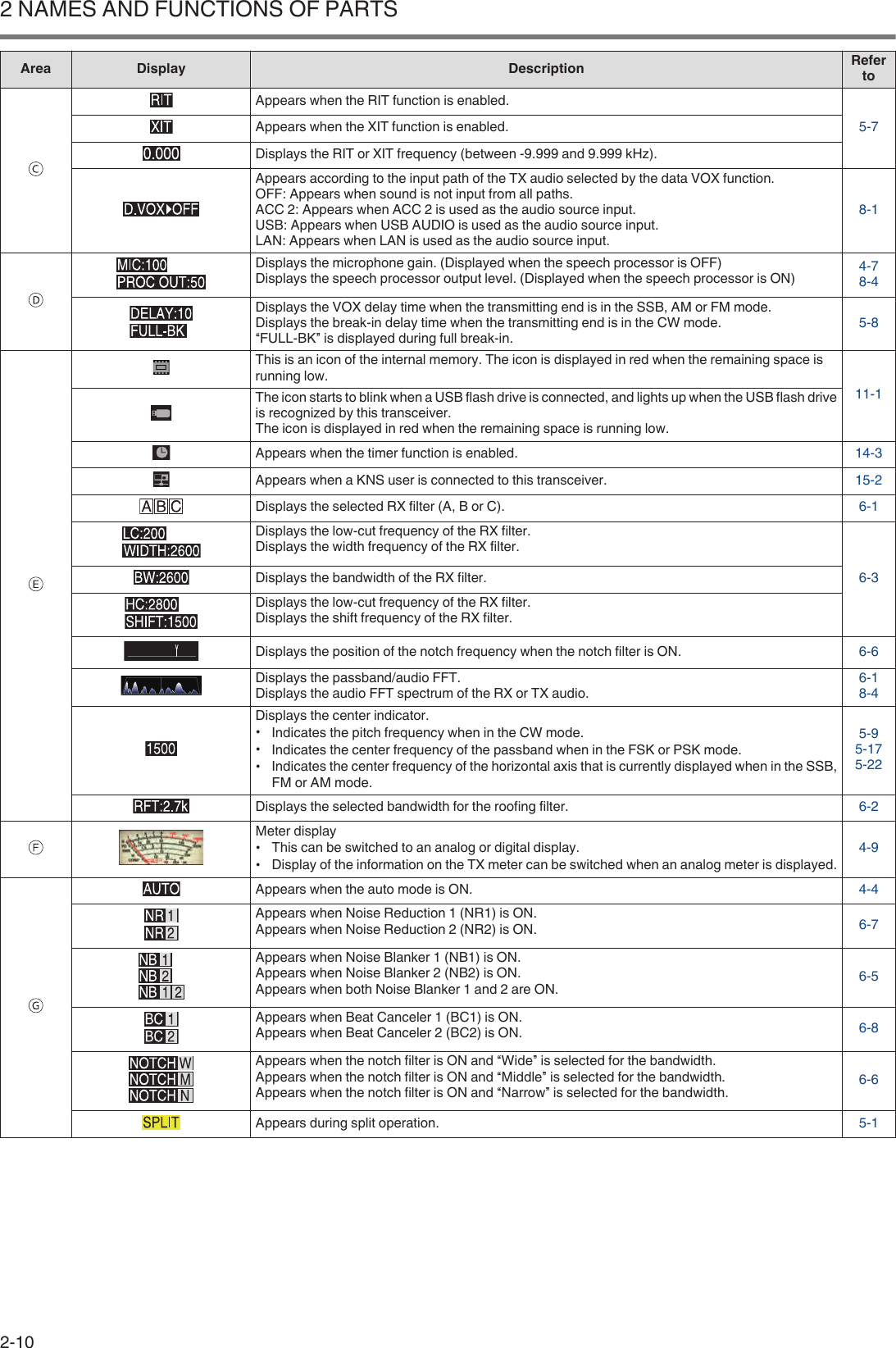
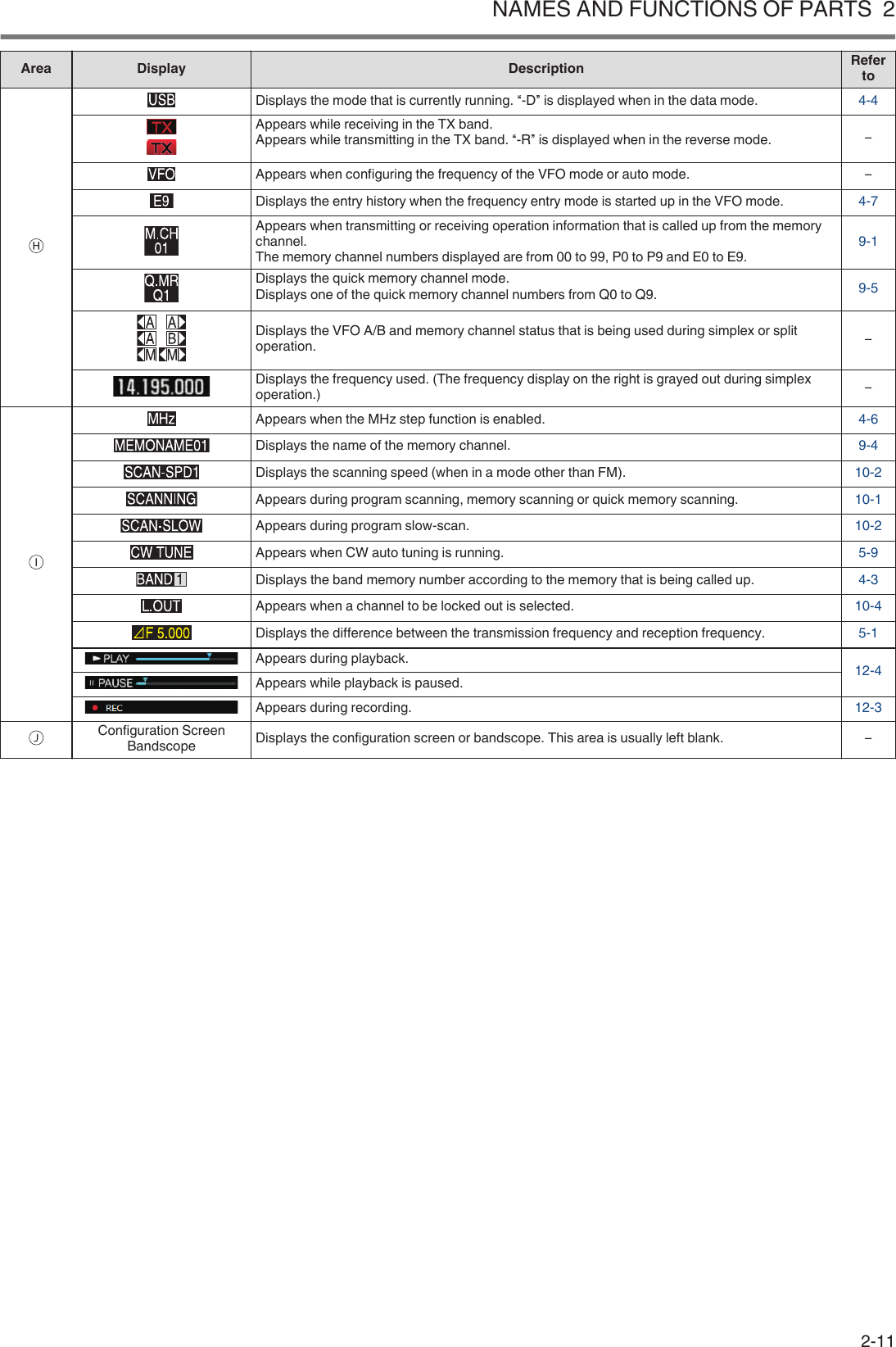
![Screen.ⒶⒷⒺⒸⒻⒼⒽⒾⒿⒹArea Display Description Referto..Appears when an RX antenna is functioning. 4-10.Displays the antenna number. Switches the antenna number accordingly when the antenna isswitched. It is not displayed when the TX output power destination of the transverter is drive output(DRV). 4-10.Appears when antenna output for the external receiver is functioning. 16-15.Appears when the receiving attenuator is configured to “6 dB”, “12 dB” or “18 dB”. 6-1.Appears when the receive preamplifier 1 is ON.Appears when the receive preamplifier 2 is ON. 5-6.Appears when AGC is OFF.Appears when AGC is configured to “FAST”.Appears when AGC is configured to “MID”.Appears when AGC is configured to “SLOW”.5-2.Appears when Tone is ON. 5-29.Appears when CTCSS is ON. 5-30.Appears when Cross Tone is ON. 5-30..Displays the antenna tuner function and operating status.<< >> lights up when the antenna tuner is ON during reception.<< >> blinks while antenna tuning is in progress.4-11.Appears when the transverter is ON. 16-15.Blinks while TX tuning is ON. 8-7.Displays the TX output power level. (Not displayed when the TX output power destination is driveoutput (DRV).)Displayed in yellow when the output power is limited by the TX output power limiter function. 4-7.Displays the drive output level. (Displayed when drive output is ON.) 4-10.Displays the keying speed. Turning the [KEY SPEED] control displays the keying speed (4 to 60words/minute) in the TX output power area for 2 seconds. 5-13.Displays the date of the local clock. The date can be displayed in the UK, US or Japanese format. 14-1.Displays the time (24-hour format).Left: Displays the time of the local clock.Right: Displays the time of the auxiliary clock (indicated by the character “U” at the end). 14-1NAMES AND FUNCTIONS OF PARTS 22-9](https://usermanual.wiki/JVC-KENWOOD/512000.Users-Manual-1/User-Guide-3944945-Page-29.png)

![Menu OperationThe settings of the different functions of this transceiver can bechanged from the menu. It can also be used to switch the operatingenvironment.There is also a list of frequently used menu items as well as “sub-menus” that are sorted by function.Calling Up a Menu1Press [MENU] to display the menu screen..2Press F2 [ ]/ F3 [ ] or [M.IN]/ [ ] toselect a group.3Press F4 [SELECT] to display the menu items of theselected group..4Press F2 [ ]/ F3 [ ] or [M.IN]/ [ ], or turnthe [MULTI/CH] control to select the desired menuitem.•Pressing F [GROUP ]/ F [GROUP ] changes thegroup. (Refer to 3-3 Menu Items.)•Pressing F [MENU TOP] returns the menu screen to the top.5Press F4 [SELECT] or [Q-MR>].The parameter setting can now be changed.6Press F4 [–]/ F5 [+] or [M.IN]/ [ ], or turn the[MULTI/CH] control to select the setting value..The setting switches to a different setting.•To restore the default setting of the selected menu, pressand hold F2 [(RESET)].7Press F1 [ ] or [<Q-M.IN].The selected content is confirmed.8Press [MENU] or [ESC] to exit the menu screen.In the subsequent descriptions on the menus, the expression“Configure in Menu [X-XX] ’Xxxx xxxx xxxxx’” will be used.(Example: Configure in Menu [3-06] “MHz Step”)Calling Up a Sub-Menu1Press [MENU] to display the menu screen.The function keys of the sub-menu are displayed on the rightside of the screen.2Press F [MORE] to switch between sub-menuselection 1 and 2.3Press the desired function key.The following sub-menus are displayed.Sub-Menu Key Guide BehaviorSub-Menu Selection 1Reset RESET Displays the Reset menu screen.Advanced ADV. Displays the Advanced Menuscreen.Linear Amplifier LINEARAMP Displays the Linear Amplifier menuscreen.Dimmer DIMMERnShort press: Switches the dimmer.Long press: Displays the Dimmermenu screen.SWL SWL Displays the horizontal dial screen.USB/File USB/FILE Displays the USB/FileManagement menu screen.MORE MORE Switches to sub-menu selection 2.Sub-Menu Selection 2Clock CLOCK Displays the Clock menu screen.LAN LAN Displays the LAN menu screen.Auto Mode AUTOMODE Displays the Auto Mode menuscreen.KNS KNS Displays the KNS menu screen.Timer TIMERShort press: Switches the pausedstate of a timer.Long press: Displays the Timermenu screen.Frequency Marker F.MKRxxxShort press: Switches the markerdisplay.Long press: Displays theFrequency Marker menu screen.MORE MORE Switches to sub-menu selection 1.Advanced MenuIn the subsequent descriptions on the advanced menus, theexpression “Configure in Advanced Menu [XX] ’Xxxx xxxxxxxxx’” will be used.(Example: Configure in Advanced Menu [9] “Antenna TunerOperation per Band”)MENU 33 MENU3-1](https://usermanual.wiki/JVC-KENWOOD/512000.Users-Manual-1/User-Guide-3944945-Page-33.png)
![Common Menu Screen Operations•Pressing F [MENU TOP] returns the menu screen to the top.•Pressing F [GROUP ]/ F [GROUP ] switches thegroup.•The menu item can be selected in the following ways.•Turn the [MULTI/CH] control.•Press F2 [ ]/ F3 [ ].•Press [M.IN]/ [ ].•Press [UP] or [DOWN] on the microphone.•The setting value in the Parameter field can be selected in thefollowing ways.•Turn the [MULTI/CH] control.•Press [UP] or [DOWN] on the microphone.•Press F4 [–]/ F5 [+].•Press [M.IN] / [].•Press [ ]/ [ ].•Pressing and holding [(RESET)] restores the altered settingvalue to the default setting.•Pressing F [MORE] switches the key guide display.•Pressing F [ TOP] when configuring the sub-menureturns the sub-menu screen to the top.Exiting the MenuTo exit configuration or editing on the menu screen or to end theconfiguration of a menu item halfway, follow the steps below. Themenu screen closes and the display returns to the normal screen.Press [MENU] or [ESC].●It is possible to reset only the menu settings.●The menu items or default values may be altered.●When editing the screen saver message or power-onmessage, pressing [MENU] will not exit the menuscreen.Switching between the CONFIG A and CONFIG BOperating Environments“Operating environment” refers collectively to values configured inthe menu as well as the different settings data for operation. Twodifferent types of operating environment are available on thistransceiver: CONFIG A and CONFIG B. Both CONFIG A andCONFIG B have the same functions and they can be configuredindependently of each other. For example, it is possible toconfigure CONFIG A for DX and CONFIG B for rag chew andswitch easily between them.1Press [MENU] to display the menu screen.The current operating environment (CONFIG A or CONFIG B)is displayed in the status bar of the menu screen. Also, data ofthe operating environment can be saved to and read from atransceiver or USB flash drive.2Press F7 [CONFIG].A message appears.•Press F7 [CANCEL] to return to the Menu screen..3Press F4 [OK].•Switches from CONFIG A to CONFIG B or vice versa, andthis transceiver automatically restarts after switching iscomplete.●The following are common settings between CONFIG Aand B.•Number of quick memory channels•Baud rate of COM port•Baud rate of USB connector (virtual COM port) on therear panel•Decoded character output●Information and data other than those below arecommon between CONFIG A and B.•Advanced menu settings•LAN menu settings•Clock menu settings•Linear amplifier menu settings•Timer menu settings•Memory channel data (including quick memory andslow scan point data)•CW/RTTY/PSK message memory data•Band memory (frequency and mode)•Broadcast band memory data•Antenna selection (including drive output selectionand antenna output selection for external receiver)•Preset data of antenna tuner•Internal audio file data of recording function (wav file)•Voice message memory data (wav file)●If the operating environment is switched while the quickmemory is called up by pressing [Q-MR>] (quickmemory), the quick memory settings will be discardedbefore the operating environment switches.3 MENU3-2](https://usermanual.wiki/JVC-KENWOOD/512000.Users-Manual-1/User-Guide-3944945-Page-34.png)
![Menu ItemsMenu- 0. Basic Configurations -Menu Display Description Setting Value Default Refer toDisplay0-00 Color Display Pattern Display color type Type 1/ Type 2/ Type 3 Type 1 4-10-01 Function Key Style Type of function key display Type 1/ Type 2/ Type 3 Type 1 4-10-02 Font Style (Frequency Display) Font type (frequency display) Font 1/ Font 2/ Font 3/ Font 4/ Font5Font 1 4-10-03 Screen Saver Screen saver Off/ Type 1/ Type 2/ Type 3/Display Off Off 16-10-04 Screen Saver Wait Time Wait time for screen saver Preview (5 [sec])/ 5/ 15/ 30/ 60 [min] Preview (5[sec]) 16-10-05 Screen Saver Message Screen saver message Up to 10 alphanumeric characters TS-890 16-10-06 Power-on Message Power on message Up to 15 alphanumeric characters HELLO 16-1Meter0-07 FM Mode S-Meter Sensitivity FM S meter sensitivity Normal/ High Normal 4-90-08 Meter Response Speed (Analog) Analog meter response 1 to 4 (1 step) 3 4-90-09 Meter Display Pattern Meter type Digital/ Analog (White)/ Analog(Black) Analog(White) 4-90-10 Meter Display Peak Hold Meter with peak hold Off/ On On 4-90-11 S-Meter Scale S meter scale Type 1/ Type 2 Type 1 4-90-12 TX Digital Meter TX meter (digital) Off/ On Off 4-9Key0-13 Long Press Duration of Panel Keys Duration for pressing and holdinga key 200 to 2000 [ms] (100 [ms] step) 500 [ms] 16-20-14 Touchscreen Tuning Touchscreen tuning Off/ On On 7-40-15 PF A: Key Assignment Function assignment to [PF A]key Refer to PF (ProgrammableFunction). VOICE1 16-20-16 PF B: Key Assignment Function assignment to [PF B]key Refer to PF (ProgrammableFunction). VOICE2 16-20-17 PF C: Key Assignment Function assignment to [PF C]key Refer to PF (ProgrammableFunction). VOICE3 16-20-18 External PF 1: Key Assignment Function assignment to [PF 1] onthe keypad Refer to PF (ProgrammableFunction).MessageMemory CH 116-30-19 External PF 2: Key Assignment Function assignment to [PF 2] onthe keypad Refer to PF (ProgrammableFunction).MessageMemory CH 216-30-20 External PF 3: Key Assignment Function assignment to [PF 3] onthe keypadRefer to PF (Programmable Function).MessageMemory CH316-30-21 External PF 4: Key Assignment Function assignment to [PF 4] onthe keypad Refer to PF (ProgrammableFunction).MessageMemory CH 416-30-22 External PF 5: Key Assignment Function assignment to [PF 5] onthe keypad Refer to PF (ProgrammableFunction).MessageMemory CH 516-30-23 External PF 6: Key Assignment Function assignment to [PF 6] onthe keypad Refer to PF (ProgrammableFunction).MessageMemory CH 616-30-24 External PF 7: Key Assignment Function assignment to [PF7] onthe keypad Refer to PF (ProgrammableFunction).MessageMemory CH 716-30-25 External PF 8: Key Assignment Function assignment to [PF 8] onthe keypad Refer to PF (ProgrammableFunction).MessageMemory CH 816-30-26 Microphone PF 1: Key Assignment Function assignment to [PF 1] onthe microphone Refer to PF (ProgrammableFunction). A/B, A=B 16-3MENU 33-3](https://usermanual.wiki/JVC-KENWOOD/512000.Users-Manual-1/User-Guide-3944945-Page-35.png)
![- 0. Basic Configurations -Menu Display Description Setting Value Default Refer toDisplay0-27 Microphone PF 2: Key Assignment Function assignment to [PF 2] onthe microphone Refer to PF (ProgrammableFunction). SPLIT 16-20-28 Microphone PF 3: Key Assignment Function assignment to [PF 3] onthe microphone Refer to PF (ProgrammableFunction). M/V, M V16-20-29 Microphone PF 4: Key Assignment Function assignment to [PF 4] onthe microphone Refer to PF (ProgrammableFunction). MONI 16-20-30 Microphone DOWN: Key Assignment Function assignment to [DOWN]on the microphone Refer to PF (ProgrammableFunction).DWN Key(Microphone)16-20-31 Microphone UP: Key Assignment Function assignment to [UP] onthe microphone Refer to PF (ProgrammableFunction).UP Key(Microphone)16-20-32 Automatic Power Off APO (Automatic Power Off) Off/ 60/ 120/ 180 [min] Off 16-2- 1. Audio Performance -Menu Display Description Setting Value Default Refer toVolume1-00 Beep Volume Volume of beep tone Off/ 1 to 20 (1 step) 10 16-21-01 Voice Message Volume (Play) Playback volume of voicemessage Off/ 1 to 20 (1 step) 10 12-21-02 Sidetone Volume Sidetone volume Off/ 1 to 20 (1 step) 10 5-9Voice Guide1-03 Voice Guidance Volume Voice guide volume Off/ 1 to 20 (1 step) 10 13-11-04 Voice Guidance Speed Voice guide speed 1 to 4 (1 step) 1 13-11-05 User Interface Language (VoiceGuidance & Messages) Language of voice guide andmessage display English/ Japanese English 13-11-06 Automatic Voice Guidance Automatic voice guide Off/ On Off 13-1- 2. Decoding & Encoding -Menu Display Description Setting Value Default Refer toFSK Decoding2-00 FFT Scope Averaging (RTTY Decode) Averaging on the FFT scope(RTTY Decode) 0 to 9 (1 step) 0 5-242-01 RX UOS RX unshift-on-space Off/ On On 5-212-02 Newline Code New line code selection (duringreception) CR+LF/ All All 5-212-03 Diddle Diddle Off/ Blank Code/ Letters Code Blank Code 5-212-04 TX UOS TX unshift-on-space Off/ On On 5-212-05 Automatic Newline Insertion Automatic new line code insertion On/ Off On 5-21FSK Key2-06 FSK Spacing FSK shift width 170/ 200/ 425/ 850 [Hz] 170 [Hz] 5-212-07 FSK Keying Polarity FSK keying polarity Off/ On Off 5-212-08 FSK Tone Frequency FSK tone frequency 1275/ 2125 [Hz] 2125 [Hz] 5-212-09 RTTY Tuning Scope Scope display for checking FSKtuning FFT Scope/ X-Y Scope FFT Scope 5-18PSK Decoding2-10 FFT Scope Averaging (PSK Decode) Averaging on the FFT scope(PSK Decode) 0 to 9 (1 step) 0 5-182-11 PSK AFC Tuning Range Tuning range for PSK AFC ±15/ ±8 [Hz] ±15 [Hz] 5-242-12 PSK Tone Frequency PSK tone frequency 1.0/ 1.5/ 2.0 [kHz] 1.5 [kHz] 5-272-13 PSK Tuning Scope Scope display for checking PSKtuning FFT Scope/ X-Y Scope FFT Scope 5-18Common2-14 CW/ RTTY/ PSK Log File Format File format for saving CW/RTTY/PSK logs html/ txt txt 5-272-15 CW/ RTTY/ PSK Time Stamp CW/ RTTY/ PSK time stamp Off/ Time Stamp/ Time Stamp +Frequency Time Stamp+ Frequency 5-272-16 Clock (CW/ RTTY/ PSK Time Stamp) Clock selection for CW/ RTTY/PSK time stamp Local Clock/ Secondary Clock Local Clock 5-272-17 Waterfall when Tuning (RTTY/ PSKAudio Scope) Selection of RTTY/ PSK waterfalldisplay type Straight/ Follow Straight 5-195-243 MENU3-4](https://usermanual.wiki/JVC-KENWOOD/512000.Users-Manual-1/User-Guide-3944945-Page-36.png)
![- 3. Controls Configurations -Menu Display Description Setting Value Default Refer toControl Rate3-00 Frequency Rounding Off (Multi/ ChannelControl) Rounds off the frequency of the[MULTI/CH] control Off/ On On 4-63-01 SSB Mode Frequency Step Size (Multi/Channel Control) SSB frequency step size 0.5/ 1/ 2.5/ 5/ 10 [kHz] 1 [kHz] 4-63-02 CW/FSK/PSK Mode Frequency StepSize (Multi/Channel Control) CW/ FSK/ PSK frequency stepsize 0.5/ 1/ 2.5/ 5/ 10 [kHz] 0.5 [kHz] 4-63-03 FM Mode Frequency Step Size (Multi/Channel Control) FM frequency step size 5/ 6.25/ 10/ 12.5/ 15/ 20/ 25/ 30/ 50/100 [kHz] 10 [kHz] 4-63-04 AM Mode Frequency Step Size (Multi/Channel Control) AM frequency step size 5/ 6.25/ 10/ 12.5/ 15/ 20/ 25/ 30/ 50/100 [kHz] 5 [kHz] 4-63-05 9 kHz Step in AM Broadcast Band (Multi/Channel Control) Steps of the [MULTI/CH] controlin the BC band (AM) Off/ On K type: OffE type: On 4-63-06 MHz Step MHz step 100/ 500/ 1000 [kHz] 1000 [kHz] 4-63-07 Tuning Control: Number of Steps perRevolution Number of steps per revolution ofthe Tuning control 250/ 500/ 1000 [Step] 1000 [Step] 4-63-08 Tuning Speed Control Fast forward rate of the Tuningcontrol Off/ 2 to 10 (1 step) Off 4-63-09 Tuning Speed Control Sensitivity Sensitivity of the Tuning controlfor starting the fast forwardoperation 1 to 10 (1 step) 5 4-63-10 Lock Function Frequency lock function Frequency Lock/ Tuning ControlLock FrequencyLock 4-63-11 Number of Band Memories Number of band memories 1/ 3/ 5 3 4-33-12 Split Frequency Offset by RIT/XITControl Changing the split frequencyusing the [RIT/XIT] controlOff/ TX Frequency Offset while RX/RX Frequency Offset while TX/Both Off 5-13-13 Band Direct Keys in Split Mode Band direct key during splitoperation RX Band/ RX Band and CancelSplit Mode/ RX/ TX Band RX Band 5-1- 4. Memory Channels & Scan -Menu Display Description Setting Value Default Refer toMemory4-00 Number of Quick Memory Channels Number of quick memorychannels 3/ 5/ 10 [ch] 5 [ch] 9-54-01 Temporary Change (Memory ChannelConfigurations) Temporary change of memoryfrequency Off/ On Off 9-3Scan4-02 Program Slow Scan Program slow scan Off/ On On 10-24-03 Program Slow Scan Range Range of program slow scan 100/ 200/ 300/ 400/ 500 [Hz] 300 [Hz] 10-34-04 Scan Hold Scan Hold Off/ On Off 10-34-05 Scan Resume Scan resume condition Time-operated/ Carrier-operated Time-operated 10-4- 5. CW Configurations -Menu Display Description Setting Value Default Refer toJack Terminals5-00 Paddle Jack Configuration (Front) PADDLE jack (front panel)function setting Straight Key/ Paddle/ Paddle (BugKey Mode) Paddle 5-135-01 Key Jack Configuration (Rear) KEY jack (rear panel) functionsetting Straight Key/ Paddle/ Paddle (BugKey Mode) Straight Key 5-13Mode5-02 Electronic Keyer Squeeze Mode Operation mode of the electronickeyer Mode A/ Mode B Mode B 5-135-03 Dot and Dash Reversed Keying Switches between dot and dashpaddle Off/ On Off 5-135-04 Paddle (Microphone Up/Down Keys) Paddle ([UP] and [DOWN] keyson microphone) Off/ On Off 5-135-05 CW BFO Side Band CW BFO sideband USB/ LSB USB 5-9MENU 33-5](https://usermanual.wiki/JVC-KENWOOD/512000.Users-Manual-1/User-Guide-3944945-Page-37.png)
![- 5. CW Configurations -Menu Display Description Setting Value Default Refer toWeight and Timing5-06 Automatic CW TX with Keying in SSBMode CW transmission by keying in theSSB mode Off/ On Off 5-95-07 Carrier Frequency Offset (SSB Mode toCW Mode)Carrier frequency correctionwhen shifting from the SSB modeto CW mode Off/ On Off 5-95-08 CW Keying Weight Ratio Keyer weight Automatic/ 2.5 to 4.0 (0.1 step) Automatic 5-135-09 CW Keying Reversed Weight Ratio Reverse keying auto weight ratio Off/ On Off 5-135-10 Interrupt Keying Insert keying Off/ On Off 5-17Memory5-11 CW Message Entry Method for registering CWmessage Text String/ Paddle Paddle 5-145-12 Contest Number Contest number 001 to 9999 (1 step) 001 5-155-13 Contest Number Format Contest number style Off/ 190 to ANO/ 190 to ANT/ 90 toNO/ 90 to NT Off 5-155-14 Channel Number (Count-up Message) Specifies the channel used for thecount-up message Off/ Channel 1 to Channel 8 Off 5-155-15 CW Rise Time CW rise time 1/ 2/ 4/ 6 [ms] 6 [ms] 5-95-16 CW/ Voice Message Retransmit IntervalTime Repeat interval for retransmittingCW/voice message 0 to 60 [s] (1 [s] step) 10 [s] 5-1712-2- 6. TX/RX Filter & Misc. -Menu Display Description Setting Value Default Refer toMessage6-00 Playback Time (Full-time Recording) Playback time for constantlyrecorded audio Last 10/ Last 20/ Last 30 [s] Last 30 [s] 12-36-01 Recording with Squelch Audio recording in tandem withsquelch Off/ On On 12-3TX Management6-02 Time-out Timer Maximum continuoustransmission time (Timeout timer) Off/ 3/ 5/ 10/ 20/ 30 [min] Off 8-86-03 TX Inhibit Inhibits transmission Off/ On Off 16-116-04 Transmit Power Step Size Fine adjustment of TX outputpower 1/ 5 [W] 5 [W] 4-86-05 ID Beep ID beep Off/ 1 to 30 [min] (1 step) Off 8-8Filter6-06 TX Filter Low Cut (SSB/AM) Low-cut frequency of the TX filter(SSB/AM) 10/ 100/ 200/ 300/ 400/ 500 [Hz] 100 [Hz] 8-56-07 TX Filter High Cut (SSB/AM) High-cut frequency of the TX filter(SSB/AM) 2500/ 2600/ 2700/ 2800/ 2900/3000/ 3500/ 4000 [Hz] 2900 [Hz] 8-56-08 TX Filter Low Cut (SSB-DATA/AM-DATA) Low-cut frequency of the TX filter(SSB-DATA/AM-DATA) 10/ 100/ 200/ 300/ 400/ 500 [Hz] 100 [Hz] 8-56-09 TX Filter High Cut (SSB-DATA/AM-DATA) High-cut frequency of the TX filter(SSB-DATA/AM-DATA) 2500/ 2600/ 2700/ 2800/ 2900/3000/ 3500/ 4000 [Hz] 2900 [Hz] 8-56-10 RX Filter Numbers Number of RX filters 2/ 3 3 6-16-11 Filter Control in SSB Mode (High/Lowand Shift/Width) Switches between High-cut/low-cut and WIDTH/SHIFT (SSB) High & Low Cut/ Shift & Width High & LowCut 6-26-12 Filter Control in SSB-DATA Mode(High/Low and Shift/Width)Switches between High-cut/low-cut and WIDTH/SHIFT (SSB-DATA) High & Low Cut/ Shift & Width Shift & Width 6-26-13 VOX Voice Delay (Microphone) Audio delay in the VOX mode(MIC) Off/ Short/ Middle/ Long Middle 8-26-14 VOX Voice Delay (Except Microphone) Audio delay in the VOX mode(excluding MIC) Off/ Short/ Middle/ Long Middle 8-26-15 Delta Frequency Display ⊿F display setting Off/ On On 5-13 MENU3-6](https://usermanual.wiki/JVC-KENWOOD/512000.Users-Manual-1/User-Guide-3944945-Page-38.png)
![- 7. Rear Connectors -Menu Display Description Setting Value Default Refer toBaud Rate7-00 Baud Rate (COM Port) Baud rate of COM connector 4800/ 9600/ 19200/ 38400/ 57600/115200 [bps] 9600 [bps] 16-57-01 Baud Rate (Virtual Standard COM) Baud rate of virtual COM(Standard) connector 9600/ 19200/ 38400/ 57600/115200 [bps] 115200 [bps] 16-57-02 Baud Rate (Virtual Enhanced COM) Baud rate of virtual COM(Enhanced) connector 9600/ 19200/ 38400/ 57600/115200 [bps] 115200 [bps] 16-127-03 Decoded Character Output Decoded character output Off/ On Off 16-12Data transfer7-04 Quick Data Transfer Quick data transfer Off/ 1 (TX/RX)/ 1 (Sub RX)/ 2 Off 16-97-05 Overwrite Location (Quick Data Transfer) Destination for data via quick datatransfer VFO/ Quick Memory QuickMemory 16-9Audio input7-06 USB: Audio Input Level USB audio input level 0 to 100 (1 step) 50 16-77-07 ACC 2: Audio Input Level Audio input level of ACC 2connector 0 to 100 (1 step) 50 16-7Audio output7-08 USB: Audio Output Level USB audio output level 0 to 100 (1 step) 100 16-77-09 ACC 2: Audio Output Level Audio output level from ACC 2connector 0 to 100 (1 step) 50 16-77-10 TX Monitor Level (Rear Connectors) TX monitor level output to the rearpanel connector Linked/ 0 to 20 (1 step) Linked 16-77-11 Audio Output Type (Rear Connectors) Format of audio output from therear panel connector All/ Received Audio only All 16-7- 8. Bandscope -Menu Display Description Setting Value Default Refer toCommon8-00 Bandscope Display during TX Bandscope display duringtransmission Off/ On Off 7-68-01 TX Audio Waveform Display Waveform display for transmittedaudio On/ Off On 8-48-02 Bandscope Maximum Hold Maximum hold time 10 [s]/ Continuous 10 [s] 7-58-03 Waterfall when Tuning (Center Mode) Waterfall display during tuning(center mode) Straight/ Follow Straight 7-28-04 Waterfall Gradation Level Gradation setting of the waterfall 1 to 10 (1 step) 7 7-48-05 Tuning Assist Line (SSB Mode) Auxiliary tuning line display (SSBonly) Off/ 300/ 400/ 500/ 600/ 700/ 800/1000/ 1500/ 2210 [Hz] Off 7-48-06 Frequency Scale (Center Mode) Frequency scale in the centermode Relative Frequency/ AbsoluteFrequency RelativeFrequency 7-28-07 Touchscreen Tuning Step Correction(SSB/ CW/ FSK/ PSK) Correction steps for touchscreentuning Off/ On On 7-5- 9. USB Keyboard -Menu Display Description Setting Value Default Refer toUSB keyboard9-00 Send Message by Function Keys Function key settings of USBkeyboard Off/ On On 16-59-01 Keyboard Language USB keyboard languageJapanese/ English (US)/ English(UK)/ French/ French (Canadian)/German/ Portuguese/ Portuguese(Brazilian)/ Spanish/ Spanish(Latin American)/ ItalianEnglish (US) 16-59-02 Repeat Delay Time Key repeat delay time for USBkeyboard 1 to 4 (1 step) 2 16-59-03 Repeat Speed Key repeat speed for USBkeyboard 1 to 32 (1 step) 1 16-5MENU 33-7](https://usermanual.wiki/JVC-KENWOOD/512000.Users-Manual-1/User-Guide-3944945-Page-39.png)
![Advanced Menu ItemsMenu Display Description Setting Value Default Refer to0Indication Signal Type (ExternalMeter 1) Target of external meter output 1 Automatic/ TX Power/ ALC/ DrainVoltage (Vd)/ Compression Level(COMP)/ Current (Id)/ SWR TX Power 16-61Indication Signal Type (ExternalMeter 2) Target of external meter output 2 Automatic/ TX Power/ ALC/ DrainVoltage (Vd)/ Compression Level(COMP)/ Current (Id)/ SWR Automatic 16-62 Output Level (External Meter 1) Level of external meter output 1 0 to 100 [%] (1 step) 50 [%] 16-63 Output Level (External Meter 2) Level of external meter output 2 0 to 100 [%] (1 step) 50 [%] 16-64 Reference Signal Source Switches the reference signal Internal/ External Internal 16-85Reference OscillatorCalibration Adjusts the frequency of the referenceoscillator -500 to +500 (1 step) 0 17-26TX Power Down withTransverter Enabled Powers down the transverter function Off/ On On 16-157 TX Hold After Antenna Tuning Holds transmission at the end of antennatuning Off/ On Off 4-118 Antenna Tuner during RX Antenna tuner behavior while receiving Off/ On Off 4-129Antenna Tuner Operation perBand Antenna tuner behavior for each band Off/ On Off 4-1210 Microphone Gain (FM Mode) FM microphone gain 0 to 100 (1 step) 50 5-2811 PKS Polarity Reverse Reversing of PSK polarity Off/ On Off 16-1212 TX Inhibit While Busy Inhibits transmission while in the BUSYstate Off/ On Off 16-1213 CTCSS Unmute for InternalSpeaker Mute behavior of CTCSS Mute/ Unmute Mute 16-814 PSQ Logic State SQL control signal logic Low/ Open Low 16-815 PSQ Reverse Condition SQL output conditions Off/ Busy/ Sql/ Send/ Busy-Send/Sql-Send Sql 16-816 PSQ/ PKS Pin Assignment(COM Connector) PSQ/PKS mode setting Off/ On Off 16-817 Virtual Standard COM Port -RTS RTS settings of virtual COM port(Standard) Flow Control/ CW Keying/ RTTYKeying/ PTT/ DATA SEND Flow Control 16-1218 Virtual Standard COM Port -DTR DTR settings of virtual COM port(Standard) Off/ CW Keying/ RTTY Keying/PTT/ DATA SEND Off 16-1219 Virtual Enhanced COM Port -RTS RTS settings of virtual COM port(Standard) Off/ CW Keying/ RTTY Keying/PTT/ DATA SEND Off 16-1220 Virtual Enhanced COM Port -DTR RTS settings of virtual COM port(Standard) Off/ CW Keying/ RTTY Keying/PTT/ DATA SEND Off 16-1221 External Display External display output Off/ On On 16-722 Resolution (External Display) Resolution settings of external display 800 x 600/ 848 x 480 800 x 600 16-723 Touchscreen Calibration Touchscreen adjustment – – 17-324 Software License Agreement Software license of this transceiver – – i25 Important Notices concerningFree Open Source Ways to obtain open source resourcesused by this transceiver – – ii26 About Various SoftwareLicense Agreements Licenses related to software used by thistransceiver – – ii27 Firmware Version Firmware version used by thistransceiver – – 17-1Reset Menu ItemsDisplay Description Refer toMenu Reset Menu reset17-1Memory Channel Reset Memory channel resetVFO Reset VFO resetStandard Reset (The Clock, TX Inhibit, andTransmit Power Upper Limit will not be reset) Standard resetFull Reset Full reset3 MENU3-8](https://usermanual.wiki/JVC-KENWOOD/512000.Users-Manual-1/User-Guide-3944945-Page-40.png)
![Linear Amplifier Menu ItemsDisplay Description Setting Value Default Refer toBand Target bands of the linear amplifier menu HF/ 50M/ 70M (E type) HF16-14Linear Amplifier Linear amplifier ON/OFF Off/ On OffKeying Logic Linear amplifier TX control Active Low/ Active High Active LowTX Delay Linear amplifier TX delay ON/OFF Off/ On OffTX Delay Time (CW/FSK/PSK) Linear amplifier TX delay time (CW/FSK/PSK) 5/ 10/ 15/ 20/ 25/ 30/ 35/ 40[ms] 15 [ms]TX Delay Time (SSB/FM/AM) Linear amplifier TX delay time(SSB/FM/AM) 5/ 10/ 15/ 20/ 25/ 30/ 35/ 40/45/ 50 [ms] 35 [ms]Internal Relay Control Linear amplifier relay control Off/ On OffExternal ALC Voltage Linear amplifier external ALC voltage -1/ -2/ -3/ -4/ -5/ -6/ -7/ -8/ -9/-10/ -11/ -12 [V] -4 [V]Dimmer Menu ItemsDimmer Display Description Setting Value Default Refer to1Display Screen brightness 5 to 100 (5-step) 1004-2LED LED brightness 5 to 100 (5-step) 1002Display Screen brightness 5 to 100 (5-step) 75LED LED brightness 5 to 100 (5-step) 753Display Screen brightness 5 to 100 (5-step) 50LED LED brightness 5 to 100 (5-step) 504Display Screen brightness 0 to 100 (5-step) 25LED LED brightness 5 to 100 (5-step) 25USB/File Management Menu ItemsDisplay Description Setting Value Default Refer toSafe Removal of USB Flash Drive Removes the USB flash drive safely – – 11-6Read Configuration Data Reads transceiver settings data – – 11-3Save Configuration Data Saves transceiver settings data – – 11-2Copy Files to PC (via USB cable) Copies files to PC (via USB cable) – – 11-4Copy Files to USB Flash Drive Copies files to USB flash drive – – 11-5Read Image Files for Screen Saver (Type 3) Reads images for screen saver – – 16-1Delete Files (Internal Memory) Deletes files stored in the internalmemory of the transceiver – – 11-5File Storage Location Configures the destination for saving files Internal Memory/ USB FlashDrive Internal Memory 11-2Format USB Flash Drive USD flash drive format – – 11-5MENU 33-9](https://usermanual.wiki/JVC-KENWOOD/512000.Users-Manual-1/User-Guide-3944945-Page-41.png)
![Display Description Setting Value Default Refer toProgrammable TimerFrequency/ModeFrequency during program timeroperation 30.000 kHz to 59.999.999 MHz 14.000.00014-3Mode during program timer operationLSB/ USB/ CW/ CW-R/ PSK/ PSK-R/ FSK/ FSK-R/ FM/ AM/ LSB-DATA/ USB-DATA/ FM-DATA/AM-DATAUSBSleep TimerSleep Timer Sleep timer Off/ 5/ 10/ 15/ 30/ 60/ 90/ 120 [min] Off 14-5Auto Mode Menu ItemsDisplay Description Setting Value Default Refer toAuto Mode Auto mode ON/OFF status Auto Mode Off/ Auto Mode On Auto ModeOff4-4Frequency Frequency category of auto mode (#0) 30.000 kHz to 59.999990 MHz 9.5 MHzMode Mode of auto mode (#0)LSB/ USB/ CW/ CW-R/ PSK/ PSK-R/ FSK/ FSK-R/ FM/ AM/ LSB-DATA/ USB-DATA/ FM-DATA/AM-DATALSBKNS Menu ItemsMenu Display Description Setting Value Default Refer to0KNS Operation (LANConnector) KNS operation (LAN connection) Off/ On (LAN)/ On (Internet) Off15-31 Administrator ID KNS administrator ID 1 to maximum 32 alphanumericcharacters Blank2 Administrator Password KNS administrator password 1 to maximum 32 alphanumericcharacters Blank3 Built-in VoIP Built-in VoIP function Off/ On On15-44 Audio Input Level (VoIP) VoIP outgoing audio input level 0 to 100 (1 step) 505 Audio Output Level (VoIP) VoIP incoming audio output level 0 to 100 (1 step) 1006 VoIP Jitter Buffer VoIP jitter absorption buffer 200/ 500/ 800 [ms] 200 [ms]7 Prohibit AF Gain Control Prohibits volume control Off/ On Off8 Access Log Log function Off/ On Off9Registered Users' RemoteOperation Remote operation by registered user Off/ On Off15-610 Session Time Session time1 [min]/ 2 [min]/ 3 [min]/ 5 [min]/ 10[min]/ 15 [min]/ 20 [min]/ 30 [min]/40 [min]/ 50 [min]/ 60 [min]/ 90[min]/ 120 [min]/ UnlimitedUnlimited11 KNS Welcome Message KNS welcome message Up to 128 single-bytealphanumeric characters BlankFrequency Marker Menu ItemsDisplay Description Setting Value Default Refer toFrequency Marker frequency (#0 to 49) 30.000 kHz to 59.999.999 MHz – 7-5MENU 33-11](https://usermanual.wiki/JVC-KENWOOD/512000.Users-Manual-1/User-Guide-3944945-Page-43.png)
