JVC RX 7030VBK 8030VBK/RX User Manual 7030VBK, 8030VBK LVT1007 002A
RX-8030VBK RX-8030VBK LVT1007-002A English, French,
User Manual: JVC RX-7030VBK RX-7030VBK, RX-7030VBK, RX-8030VBK English, French,
Open the PDF directly: View PDF ![]() .
.
Page Count: 109 [warning: Documents this large are best viewed by clicking the View PDF Link!]
For Customer Use:
Enter below the Model No. and Serial
No. which are located either on the rear,
bottom or side of the cabinet. Retain this
information for future reference.
Model No.
Serial No.
LVT1007-002A[C]
RX-8030VBK
RX-7030VBK
231
564
89
7/P
0+10
MENU
ENTER
CONTROL
A/V CONTROL RECEIVER
10/0
(For RX-8030VBK)
(For RX-8030VBK)
INSTRUCTIONS
MANUEL D’INSTRUCTIONS
AUDIO/VIDEO CONTROL RECEIVER
AMPLI/TUNER DE COMMANDE AUDIO/VIDEO
English
Français
COVER_8030&7030[C]7.pm6 03.2.13, 2:53 PM1
G-1
WARNING: TO REDUCE THE RISK OF FIRE
OR ELECTRIC SHOCK, DO NOT EXPOSE
THIS APPLIANCE TO RAIN OR MOISTURE.
CAUTION
To reduce the risk of electrical shocks, fire, etc.:
1. Do not remove screws, covers or cabinet.
2. Do not expose this appliance to rain or moisture.
ATTENTION
Afin d’éviter tout risque d’électrocution, d’incendie, etc.:
1. Ne pas enlever les vis ni les panneaux et ne pas ouvrir le
coffret de l’appareil.
2. Ne pas exposer l’appareil à la pluie ni à l’humidité.
Warnings, Cautions and Others/
Mises en garde, précautions et indications diverses
Caution –– STANDBY/ON button!
Disconnect the mains plug to shut the power off completely. The
STANDBY/ON button in any position does not disconnect
the mains line. The power can be remote controlled.
Attention –– Commutateur STANDBY/ON!
Déconnecter la fiche de secteur pour couper complètement le
courant. Le commutateur STANDBY/ON ne coupe jamais
complètement la ligne de secteur, quelle que soit sa position. Le
courant peut être télécommandé.
CAUTION: TO REDUCE THE RISK OF ELECTRIC SHOCK.
DO NOT REMOVE COVER (OR BACK)
NO USER SERVICEABLE PARTS INSIDE.
REFER SERVICING TO QUALIFIED SERVICE PERSONNEL.
RISK OF ELECTRIC SHOCK
DO NOT OPEN
The lightning flash with arrowhead symbol,
within an equilateral triangle is intended to
alert the user to the presence of uninsulated
"dangerous voltage" within the product’s
enclosure that may be of sufficient
magnitude to constitute a risk of electric
shock to persons.
The exclamation point within an equilateral
triangle is intended to alert the user to the
presence of important operating and
maintenance (servicing) instructions in the
literature accompanying the appliance.
CAUTION
Note to CATV system installer:
This reminder is provided to call the CATV system installer’s
attention to Section 820-40 of the NEC which provides guidelines
for proper grounding and, in particular, specifies that the cable
ground shall be connected to the grounding system of the
building, as close to the point of cable entry as practical.
Safety_8030&7030[C]7.pm6 03.2.13, 2:51 PM1

G-2
For Canada/pour Le Canada
THIS DIGITAL APPARATUS DOES NOT EXCEED THE CLASS
B LIMITS FOR RADIO NOISE EMISSIONS FROM DIGITAL
APPARATUS AS SET OUT IN THE INTERFERENCE-CAUSING
EQUIPMENT STANDARD ENTITLED “DIGITAL APPARATUS,”
ICES-003 OF THE DEPARTMENT OF COMMUNICATIONS.
CET APPAREIL NUMERIQUE RESPECTE LES LIMITES DE
BRUITS RADIOELECTRIQUES APPLICABLES AUX APPAREILS
NUMERIQUES DE CLASSE B PRESCRITES DANS LA NORME
SUR LE MATERIEL BROUILLEUR; “APPAREILS
NUMERIQUES”, NMB-003 EDICTEE PAR LE MINISTRE DES
COMMUNICATIONS.
For Canada/pour le Canada
CAUTION: TO PREVENT ELECTRIC SHOCK, MATCH WIDE
BLADE OF PLUG TO WIDE SLOT, FULLY INSERT
ATTENTION: POUR EVITER LES CHOCS ELECTRIQUES,
INTRODUIRE LA LAME LA PLUS LARGE DE LA FICHE DANS LA
BORNE CORRESPONDANTE DE LA PRISE ET POUSSER
JUSQUAU FOND
For U.S.A
This equipment has been tested and found to comply with the limits
for a Class B digital device, pursuant to part 15 of the FCC Rules.
These limits are designed to provide reasonable protection against
harmful interference in a residential installation.
This equipment generates, uses and can radiate radio frequency
energy and, if not installed and used in accordance with the
instructions, may cause harmful interference to radio
communications. However, there is no guarantee that interference
will not occur in a particular installation. If this equipment does cause
harmful interference to radio or television reception, which can be
determined by turning the equipment off and on, the user is
encouraged to try to correct the interference by one or more of the
following measures:
Reorient or relocate the receiving antenna.
Increase the separation between the equipment and receiver.
Connect the equipment into an outlet on a circuit different from that
to which the receiver is connected.
Consult the dealer or an experienced radio/TV technician for help.
Changes or modifications not expressly approved by the
manufacturer for compliance could void the user s authority to
opratethe equipment.
Safety_8030&7030[C]7.pm6 03.2.13, 2:51 PM2
G-3
Caution: Proper Ventilation
To avoid risk of electric shock and fire and to protect from dam-
age.
Locate the apparatus as follows:
Front: No obstructions open spacing.
Sides: No obstructions in 10 cm from the sides.
Top: No obstructions in 10 cm from the top.
Back: No obstructions in 15 cm from the back
Bottom: No obstructions, place on the level surface.
In addition, maintain the best possible air circulation as illus-
trated.
Attention: Ventilation Correcte
Pour éviter les chocs électriques, l’incendie et tout autre dégât.
Disposer l’appareil en tenant compte des impératifs suivants
Avant: Rien ne doit gêner le dégagement
Flancs: Laisser 10 cm de dégagement latéral
Dessus: Laisser 10 cm de dégagement supérieur
Arrière: Laisser 15 cm de dégagement arrière
Dessous: Rien ne doit obstruer par dessous; poser l’appareil
sur une surface plate.
Veiller également à ce que l’air circule le mieux possible comme
illustré.
Spacing 15 cm or more
Dégagement de 15 cm ou plus
RX-8030VBK/RX-7030VBK
Wall or obstructions
Mur, ou obstruction Front
Avant
Stand height 15 cm or more
Hauteur du socle: 15 cm ou plus
Floor
Plancher
Safety_8030&7030[C]7.pm6 03.2.13, 2:51 PM3

1
English
Table of Contents
Basic Settings ........................................... 25
Setting the Speakers Configuration .......................................... 25
Basic Setting Items ................................................................... 26
Basic Procedure ........................................................................ 27
Setting the Speakers ........................................................... 27
Setting the Speaker Distance ............................................. 28
Setting the Bass Sounds ..................................................... 28
Selecting main or sub channel—DUAL MONO ............... 29
Setting the Digital Input Terminals .................................... 29
Setting the Component Video Input ................................... 30
Memorizing the Volume Level for Each Source ................ 30
Adjusting Sound ........................................ 31
Basic Setting Items ................................................................... 31
Basic Procedure ........................................................................ 31
Adjusting the Equalization Patterns ................................... 32
Adjusting the Speaker Output Levels ................................ 32
Adjusting the Sound Parameters for the
Surround and DSP modes ............................................ 33
Using the Surround Modes ..........................
34
Reproducing Theater Ambience ................................................ 34
Introducing the Surround Modes ............................................. 34
Surround Modes Applicable to the Various Software .............. 36
Activating the Surround Modes ............................................... 37
7 Activating the EX/ES setting ................................................ 37
7 Activating the Surroung modes ............................................ 37
Using the DSP Modes ................................ 38
Reproducing the Sound Field ................................................... 38
Introducing the DSP Modes ..................................................... 38
Activating the DSP Modes ....................................................... 39
Using the DVD MULTI Playback Mode .......... 40
Activating the DVD MULTI Playback Mode .......................... 40
COMPU LINK Remote Control System ......... 41
AV COMPU LINK Remote Control System .... 42
Operating JVC’s Audio/Video Components ... 44
Operating Audio Components .................................................. 44
Operating Video Components .................................................. 46
Operating Other Manufacturers’ Video
Equipment ............................................ 47
Troubleshooting ......................................... 50
Specifications............................................ 51
Introduction ................................................ 2
Features ...................................................................................... 2
Precautions ................................................................................. 2
Parts Identification ...................................... 3
Remote Control .......................................................................... 3
Front Panel ................................................................................. 4
Rear Panel .................................................................................. 6
Getting Started ........................................... 8
Before Installation ...................................................................... 8
Checking the Supplied Accessories ........................................... 8
Putting Batteries in the Remote Control .................................... 8
Connecting the FM and AM Antennas ....................................... 8
Connecting the Speakers ............................................................ 9
Connecting Audio/Video Components ..................................... 11
7 Analog Connections ............................................................. 11
7 Digital Connections .............................................................. 16
Connecting the Power Cord ..................................................... 16
Basic Operations ....................................... 17
Daily Operational Procedure .................................................... 17
Turning On the Power .............................................................. 17
Selecting the Source to Play ..................................................... 17
Adjusting the Volume ............................................................... 18
Selecting the Front Speakers .................................................... 19
Activating and Adjusting the Subwoofer Sound ...................... 19
Selecting the Analog or Digital Input Mode ............................ 19
Setting the Dynamic Range ...................................................... 20
Attenuating the Input Signal .................................................... 20
Turning Analog Direct On and Off .......................................... 21
Making Sounds Natural............................................................ 21
Changing the Source Name ...................................................... 21
Reinforcing the Bass ................................................................ 22
Muting the Sound ..................................................................... 22
Changing the Display Brightness ............................................. 22
Using the Sleep Timer .............................................................. 22
Receiving Radio Broadcasts ........................ 23
Tuning in to Stations Manually ................................................ 23
Using Preset Tuning ................................................................. 23
Selecting the FM Reception Mode ........................................... 24
This mark indicates that ONLY the remote control
CAN be used for the operation explained.
This mark indicates that the remote control
CANNOT be used for the operation explained.
Use the buttons on the front panel.
Features with this mark are provided only for
RX-8030VBK.
Features with this mark are provided only for
RX-7030VBK.
RX-8030V
ONLY
RX-7030V
ONLY
Remote
NOT
01-16_8030&7030[C]7.pm6 03.2.13, 2:51 PM1

2
English
Introduction
We would like to thank you for purchasing one of our JVC products.
Before operating this unit, read this manual carefully and thoroughly to obtain the best possible performance
from your unit, and retain this manual for future reference.
Features
CC (Compensative Compression) converter
—ONLY for RX-8030VBK
CC Converter eliminates jitter and ripples, achieving a drastic
reduction in digital distortion by processing the digital music data
in 24 bit–quantization and by expanding the sampling frequency
to 128 kHz (for fs 32 kHz signals)/176.4 kHz (for fs 44.1 kHz
signals)/192 kHz (for fs 48 kHz signals). By using the CC
Converter, you can obtain a natural sound field from any source.
(See page 21 for details.)
K2 technology—ONLY for RX-8030VBK
K2 technology has been designed to enable natural audio
reproduction, achieving a drastic reduction in digital distortion
and creating original sound ambience with high precision.
Compatible with various audio formats including
DTS 96/24
RX-8030VBK and RX-7030VBK allow you to enjoy a newly
introduced audio format such as Dolby Digital EX, Dolby Pro
Logic II, DTS-ES, DTS Neo:6, and DTS 96/24.
• This unit is also compatible with Dual Mono signals recorded in
Dolby Digital and DTS discs.
DAP (Digital Acoustic Processor)
Sound field simulation technology allows precise ambience
recreation of existing theaters and halls. Thanks to the high-
performance DSP (Digital Signal Processor) and high-capacity
memory, you can enjoy multi-channel surround sound by playing
2-channel or multi-channel software according to the speaker
setting.
Multi-channel headphone virtual surround
sound—3D HEADPHONE Mode
The built-in headphone virtual surround system is compatible with
Multi-channel software like Dolby Digital, DTS Surround, etc.
Thanks to the new signal processing algorithms used by the high-
performance DSP, you can enjoy a natural surround sound through
the headphones.
COMPU LINK/AV COMPU LINK remote control
systems
These COMPU LINK remote control systems allow you to
operate other JVC’s audio/video components from this receiver.
Precautions
Power sources
• When unplugging the receiver from the wall outlet, always pull
the plug, not the AC power cord.
• Do not handle the AC power cord with wet hands.
• If you are not going to operate the receiver for an extended period
of time, unplug the AC power cord from the wall outlet.
Ventilation
High power amplifiers built in this receiver will generate heat inside
the cabinet. For safety, observe the following carefully.
• Make sure there is good ventilation around the receiver. Poor
ventilation could overheat and damage the receiver.
• Do not block the ventilation openings or holes. (If the ventilation
openings or holes are blocked by a newspaper or cloth, etc., the
heat may not be able to get out.)
Others
• Should any metallic object or liquid fall onto the unit, unplug the
unit and consult your dealer before operating any further.
• Do not expose this apparatus to rain, moisture, dripping or
splashing and that no objects filled with liquids, such as vases
shall be placed on the apparatus.
• Do not disassemble the unit since there are no user serviceable
parts inside.
If anything goes wrong, unplug the AC power cord and consult your
JVC dealer.
01-16_8030&7030[C]7.pm6 03.2.13, 2:51 PM2
3
English
Parts Identification
1Only for RX-8030VBK: Display window
• When the remote operation mode changes, it is shown on
this display.
• Signal transmission indicator (A) lights up when
transmitting signals.
2 buttons (17, 46 – 48)
•For RX-8030VBK:
CATV/DBS , VCR 1 , TV , AUDIO
•For RX-7030VBK:
CATV/DBS , VCR , TV , AUDIO
3Source selection buttons (17, 18, 19, 23, 24, 37, 40)
•For RX-8030VBK:
DVD MULTI, DVD, CD*, FM/AM*, VCR 1, VCR 2,
CDR*, TAPE/MD*, TV/DBS, VIDEO, PHONO*
•For RX-7030VBK:
DVD MULTI, DVD, CD*, FM/AM*, TV/DBS, VCR,
TAPE/CDR*
* When you press one on these source selection buttons on the
remote control, the receiver automatically turns on.
4• SURROUND button (37)
• DSP button (39)
• SURR (surround)/DSP OFF button (37, 39)
• EX/ES button (37)
5•For RX-8030VBK: CC CONVERTER button (21)
•For RX-7030VBK: CD DISC button (45)
6MIDNIGHT MODE button (20)
7SOUND button (22, 32, 33)
8CATV/DBS CONTROL button (47)
9TV/VIDEO button (46, 47)
p•For RX-8030VBK: CONTROL button (44 – 46)
•For RX-7030VBK: VCR CONTROL button (46)
qREC PAUSE button (45, 46, 48)
wSLEEP button (22)
eANALOG/DIGITAL INPUT button (20)
rANALOG DIRECT button (21)
t• 10 keys for operating the tuner (24)
• 10 keys for adjusting sound (32, 33)
• 10 keys for operating audio/video components (44 – 48)
y• CH (channel) +/– buttons (46 – 48)
• *LEVEL +/– buttons (32, 33, 44)
The LEVEL +/– buttons function only after pressing SOUND
then 10 keys which are marked with an asterisk (*) on the
remote control.
uVOLUME +/– buttons (18)
iTV VOL (volume) +/– buttons (46, 47)
oMUTING button (22)
;• TUNING UP/DOWN buttons (23)
• Operating buttons for audio/video components (44 – 46, 48)
3, 8, 7, 4/REW, FF/¢
aDIMMER button (22)
åOnly for RX-7030VBK: TAPE/CDR CONTROL button (45)
Remote Control
RX-8030VBK RX-7030VBK
+
−
+
−
+
−
231
564
89
7/P
0
+10
MENU
ENTER
BASS BOOST
TEST
∗
CENTER
∗
SUB WOOFER
∗
DIGITAL EQ
∗
SURR BACK
CH/
∗
LEVEL
TV VOL
/REW
DOWN — TUNING — UP
FF/
MUTING
DIMMER
VOLUME
CATV/DBS
CONTROL
TV/VIDEO
REC PAUSE
SLEEP
RETURN FM MODE 100+
CONTROL
REMOTE CONTROL
RM-SRX8030J
CATV/DBS VCR 1 TV AUDIO
DSP
OFF
DVD MULTI CD
CDR TAPE/MD
TV/DBS VIDEO PHONO
FM/AM
VCR 1 VCR 2
SURROUND
EX/ES
CC CONVERTER
SURR/DSP
ANALOG/DIGITAL
A/V CONTROL RECEIVER
INPUT
MIDNIGHT
MODE
DIRECT
ANALOG
DVD
u
i
1
3
4
9
p
q
w
t
;
a
10/0
y
2
SOUND
8
6
5
7
o
r
e
A
+
−
+
−
+
−
231
564
89
7/P
0+10
MENU
ENTER
TESTCD DISC
∗
CENTER
∗
SUB WOOFER
∗DIGITAL EQ ∗SURR BACK
CH/∗LEVEL
TV VOL
/REW
DOWN — TUNING — UP
FF/
MUTING
DIMMER
VOLUME
CATV/DBS
CONTROL
VCR
CONTROL TAPE/CDR
CONTROL
TV/VIDEO
REC PAUSE
SLEEP
RETURN FM MODE 100+
REMOTE CONTROL
RM-SRX7030J
CATV/DBS VCR TV AUDIO
DSP
OFF
DVD MULTI CD
TAPE/CDR
ANALOG/DIGITAL
FM/AM
TV/DBS VCR
SURROUND
EX/ES
SURR/DSP
A/V CONTROL RECEIVER
INPUT
MIDNIGHT
MODE
DIRECT
ANALOG
DVD
u
i
3
4
9
p
q
w
t
;
a
10/0
y
2
SOUND
8
6
5
7
o
r
e
s
BASS BOOST
01-16_8030&7030[C]7.pm6 03.2.13, 2:51 PM3
4
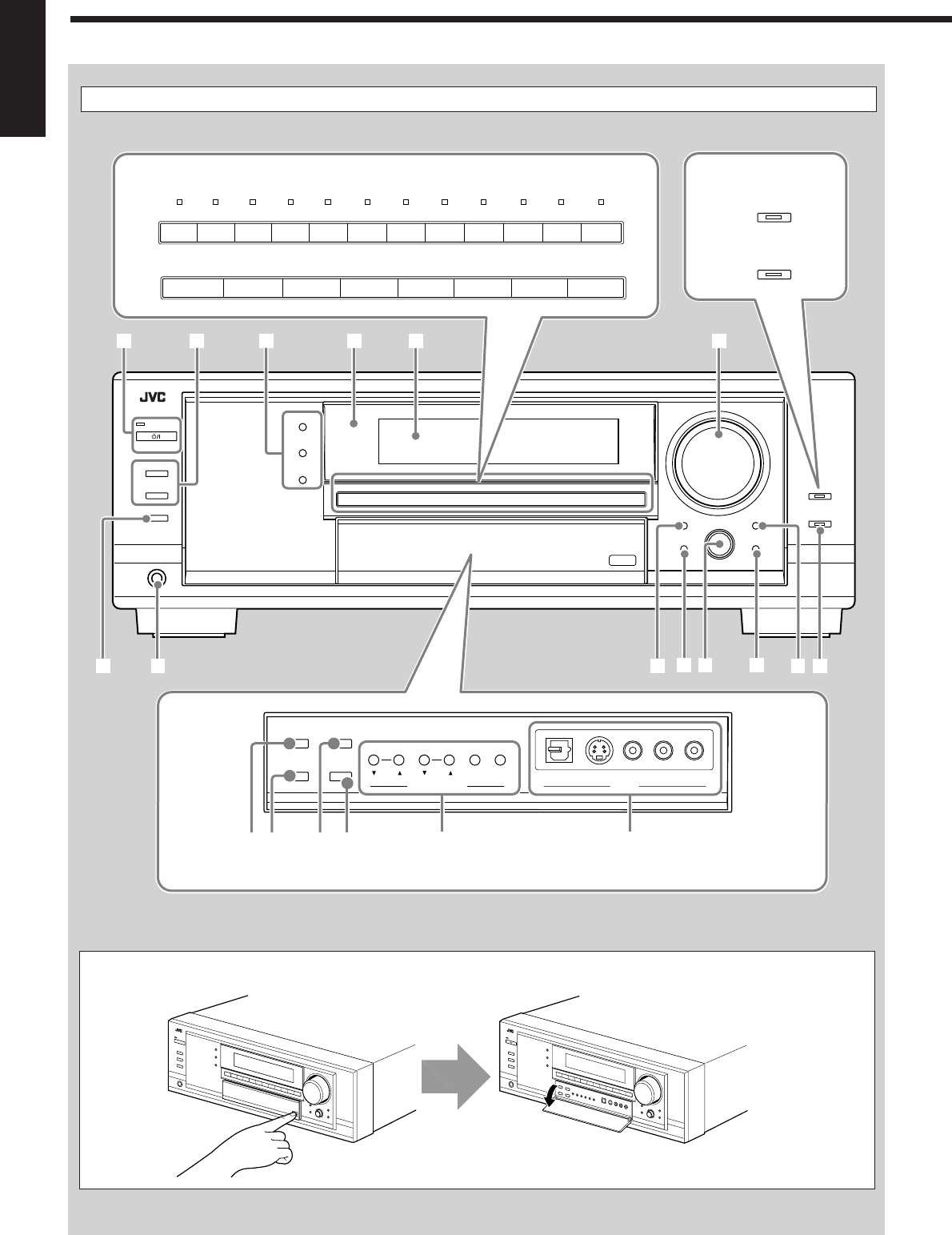
English
Display Window
Front Panel
Press down on PUSH OPEN.
How to open the front door
SUBWOOFER OUT ON/OFF
SPEAKERS ON/OFF
PHONES
1
STANDBY
ANALOG DIRECT
2
STANDBY/ON
TUNER CONTROL
SETTING ADJUST
QUICK SPEAKER
SETUP EXIT
MIDNIGHT
MODEEX / ES
INPUT ATT
INPUT
ANALOG
INPUT
DIGITAL
FM/AM TUNING FM/AM PRESET FM MODE MEMORY
SURROUND
DSP
SURROUND/ DSP
OFF
VIDEO
L—AUDIO—RDIGITAL S-VIDEO VIDEO
PUSH SET
MULTI JOG
MASTER VOLUME
12
;s
ia
4 5 7
u o
p
9
3
PUSH OPEN
CC CONVERTER
BASS BOOST
8RX-8030VBK
RX-7030VBK
Only for RX-8030VBK
Inside the front door
TUNER CONTROL
MIDNIGHT
MODEEX / ES
INPUT ATT
INPUT
ANALOG
INPUT
DIGITAL
FM/AM TUNING FM/AM PRESET FM MODE MEMORY
VIDEO
L—AUDIO—RDIGITAL S-VIDEO VIDEO
r
eq wy
t
6
TV SOUND
/DBS
VIDEOVCR 2VCR 1
DVDDVD MULTI AMFMTAPE/MDCDRCDPHONO
TV SOUND/DBSVCR
DVDDVD MULTI AMFMTAPE/CDRCD
RX-8030VBK
RX-7030VBK
01-16_8030&7030[C]7.pm6 03.2.13, 2:51 PM4
5
English
Front Panel
1 STANDBY/ON button and STANDBY lamp (17)
2• SPEAKERS ON/OFF 1 button (19)
• SPEAKERS ON/OFF 2 button (19)
3• SURROUND button (37)
• DSP button (39)
• SURROUND/DSP OFF button (37, 39)
4Remote sensor
5Display window (17)
6•For RX-8030VBK: Source selection buttons and lamps
(17, 18, 19, 21, 23, 24, 37, 40)
DVD MULTI, DVD, VCR 1, VCR 2, VIDEO,
TV SOUND/DBS, PHONO, CD, CDR, TAPE/MD, FM, AM
(The lamp above the button for selected source lights up.)
•For RX-7030VBK: Source selection buttons
(17, 18, 19, 21, 23, 24, 37, 40)
DVD MULTI, DVD, VCR , TV SOUND/DBS, CD,
TAPE/CDR, FM, AM
7MASTER VOLUME control (18)
8•For RX-8030VBK: CC CONVERTER button and lamp (21)
•For RX-7030VBK: BASS BOOST button and lamp (22)
9SUBWOOFER OUT ON/OFF button (19)
pPHONES jack (19)
qEX/ES button (37)
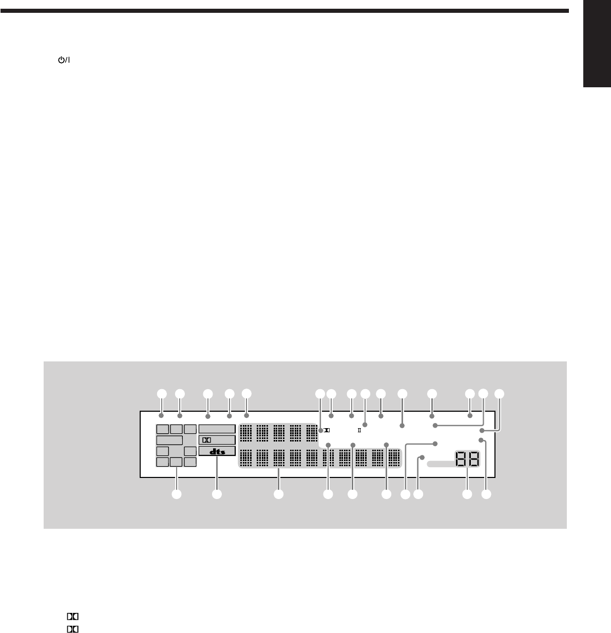
Display Window
1DUAL indicator (35)
2ANALOG indicator (20)
3DIGITAL AUTO indicator (20)
496/24 indicator (35)
5MULTI indicator (40)
6• PRO LOGIC indicator (34)
• PRO LOGIC II indicator (35)
7TUNED indicator (23)
8STEREO indicator (23, 24)
9NEO:6 indicator (35)
0AUTO MUTING indicator (24)
-VIRTUAL SB (Surround Back) indicator (34, 35)
=ONE TOUCH OPERATION indicator (30)
w• INPUT ANALOG button (20)
• INPUT ATT button (20)
eMIDNIGHT MODE button (20)
rINPUT DIGITAL button (20)
tTUNER CONTROL buttons
• FM/AM TUNING 5 / ∞ buttons (23)
• FM/AM PRESET 5 / ∞ buttons (23, 24)
• FM MODE button (24)
• MEMORY button (23)
yOnly for RX-8030VBK: VIDEO input jacks (13)
DIGITAL optical terminal, S-VIDEO jack, VIDEO jack,
AUDIO—L/R jacks
uSETTING button (27)
iQUICK SPEAKER SETUP button (25)
o• MULTI JOG control (25, 27, 31)
• PUSH SET button (25, 27, 31)
;EXIT button (27, 31)
aADJUST button (31)
sANALOG DIRECT button and lamp (21)
~SLEEP indicator (22)
!MIDNIGHT MODE indicator (20)
@DIGITAL EQ (equalization) indicator (32)
#Speaker and signal indicators (18)
$Digital signal format indicators (20)
%Main Display (17)
^DSP indicator (19, 38)
&3D-PHONIC indicator (38)
*HEADPHONE indicator (19, 38)
(SPEAKERS 1/2 indicators (19)
)INPUT ATT (attenuator) indicator (20)
_VOLUME level indicator (17, 22)
+BASS BOOST indicator (22)
Display Window
DIGITAL EQ
INPUT ATT
SLEEP
VOLUME
ONE TOUCH OPERATION
3D - PHONIC
NEO:6 VIRTUAL SB MIDNIGHT MODE
AUTO MUTING
TUNED STEREO
LINEAR PCM
DIGITAL
L
SUBWFR
LS RS
CR
S
LFE
DUAL DIGITAL AUTO
ANALOG 96/24 MULTI
PRO LOGIC
DSP
HEADPHONE SPEAKERS 1 2 BASS BOOST
SB
# $ % _
1 2 34567 8 0
9-= ~
+
^ & *
@
!
()
01-16_8030&7030[C]7.pm6 03.2.13, 2:51 PM5
6
English
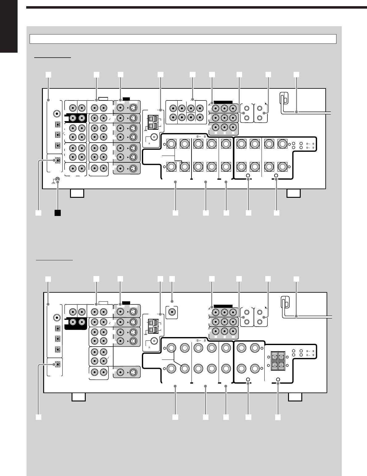
Rear Panel
RX-8030VBK
RX-7030VBK
VIDEO
RIGHT LEFT
L
R
L
R
S-VIDEO
VIDEO SURR BACK SURR CENTER FRONT
AUDIO
DIGITAL IN
DIGITAL 1 (DVD)
DIGITAL 2 (CD)
DIGITAL 3 (TV)
DIGITAL 4 (CDR)
PCM/ DOLBY DIGITAL
/ DTS
DIGITAL OUT
FM 75
COAXIAL
AM
EXT
AM
LOOP
RIGHT LEFT
+
–
+
–
12
CENTER
SPEAKER
SURROUND SPEAKERS
816
CAUTION : SPEAKER IMPEDANCE
MONITOR
OUT
SUBWOOFER CENTER
DVD
IN
OUT
(REC)
TAPE
MD
IN
(PLAY)
OUT
(REC)
CDR
IN
(PLAY)
PHONO
IN
FRONT
TV SOUND
DBS
IN
VCR 2
VCR 1
IN
(PLAY)
IN
(PLAY)
OUT
(REC)
OUT
(REC)
CD
IN
RIGHT LEFT
DVD
IN ANTENNA
SUBWOOFER
COMPONENT VIDEO
MONITOR
OUT
DBS
IN
DVD
IN
YPBPR
COMPU LINK-4
(SYNCHRO)
AV
COMPULINK-
SURROUND BACK SPEAKERS
FRONT SPEAKERS
RIGHT LEFT RIGHT LEFT RIGHT LEFT
CAUTION : SPEAKER IMPEDANCE
SINGLE USE
See Instruction
Manual For
Connection
1
OR
2 :
816
1
AND
2 :
16 32
PREOUT
SURR
(REAR)
12
3456789
trewq
py
VIDEO
RIGHT LEFT S-VIDEO
VIDEO
AUDIO
DIGITAL IN
DIGITAL 1 (DVD)
DIGITAL 2 (CD)
DIGITAL 3 (TV)
DIGITAL 4 (CDR)
PCM/ DOLBY DIGITAL
/ DTS
DIGITAL OUT
FM 75
COAXIAL
AM
EXT
AM
LOOP
RIGHT LEFT
+
–
+
–
12
CENTER
SPEAKER
SURROUND SPEAKERS
816
CAUTION : SPEAKER IMPEDANCE
MONITOR
OUT
SUBWOOFER CENTER
DVD
IN
SURR
(REAR)
TAPE
CDR
FRONT
TV SOUND
DBS
IN
VCR
IN
(PLAY)
IN
(PLAY)
OUT
(REC)
OUT
(REC)
CD
IN
RIGHT LEFT
DVD
IN ANTENNA
COMPONENT VIDEO
MONITOR
OUT
DBS
IN
DVD
IN
YP
B
P
R
COMPU LINK-4
(SYNCHRO)
AV
COMPULINK-
SURROUND BACK SPEAKERS
RIGHT LEFT RIGHT LEFT
RIGHT LEFT
CAUTION : SPEAKER IMPEDANCE
SINGLE USE
See Instruction
Manual For
Connection
1
OR
2 :
816
1
AND
2 :
16 32
SUBWOOFER
OUT
+ +
– –
123456789
reqp w
FRONT SPEAKERS
t
01-16_8030&7030[C]7.pm6 03.2.13, 2:51 PM6

7
English
Rear Panel
RX-8030VBK
1DIGITAL IN terminals (16)
• Coaxial: DIGITAL 1 (DVD)
• Optical: DIGITAL 2 (CD), DIGITAL 3 (TV),
DIGITAL 4 (CDR)
2AUDIO input/output jacks (11 – 15)
• Input: DVD IN—FRONT, CENTER, SUBWOOFER,
SURR (REAR), TV SOUND/DBS IN,
VCR 1 IN (PLAY), VCR 2 IN (PLAY), CD IN,
TAPE/MD IN (PLAY), CDR IN (PLAY),
PHONO IN
• Output: VCR 1 OUT (REC), VCR 2 OUT (REC),
TAPE/MD OUT (REC), CDR OUT (REC)
3S-VIDEO and composite VIDEO input/output jacks (14, 15)
• Input: DVD IN, TV SOUND/DBS IN, VCR1 IN (PLAY),
VCR 2 IN (PLAY)
• Output: VCR 1 OUT (REC), VCR 2 OUT (REC),
MONITOR OUT
4FM/AM ANTENNA terminals (8)
5PREOUT jacks (10, 11)
• FRONT, CENTER, SUBWOOFER, SURR, SURR BACK
6COMPONENT VIDEO input/output jacks (14, 15)
• Input: DVD IN, DBS IN
• Output: MONITOR OUT
7COMPU LINK-4 (SYNCHRO) terminals (41)
8AV COMPULINK-III terminals (42)
9AC power cord (16)
pDIGITAL OUT terminal (16)
qSURROUND BACK SPEAKERS terminal (10)
wSURROUND SPEAKERS terminal (10)
eCENTER SPEAKER terminal (10)
rFRONT SPEAKERS 1 terminals (10)
tFRONT SPEAKERS 2 terminals (10)
ÔEarth (ground) terminal (11)
RX-7030VBK
1DIGITAL IN terminals (16)
• Coaxial: DIGITAL 1 (DVD)
• Optical: DIGITAL 2 (CD), DIGITAL 3 (TV),
DIGITAL 4 (CDR)
2AUDIO input/output jacks (12 – 15)
• Input: DVD IN—FRONT, CENTER, SUBWOOFER,
SURR (REAR), TV SOUND/DBS IN,
VCR IN (PLAY), TAPE/CDR IN (PLAY), CD IN
• Output: VCR OUT (REC), TAPE/CDR OUT (REC)
3S-VIDEO and composite VIDEO input/output jacks (14, 15)
• Input: DVD IN, TV SOUND/DBS IN, VCR IN (PLAY)
• Output: VCR OUT (REC), MONITOR OUT
4FM/AM ANTENNA terminals (8)
5SUBWOOFER OUT jack (10)
6COMPONENT VIDEO input/output jacks (14, 15)
• Input: DVD IN, DBS IN
• Output: MONITOR OUT
7COMPU LINK-4 (SYNCHRO) terminals (41)
8AV COMPULINK-III terminals (42)
9AC power cord (16)
pDIGITAL OUT terminal (16)
qSURROUND BACK SPEAKERS terminal (10)
wSURROUND SPEAKERS terminal (10)
eCENTER SPEAKER terminal (10)
rFRONT SPEAKERS 1 terminals (10)
tFRONT SPEAKERS 2 terminals (10)
RX-8030VBK
RX-7030VBK
PREOUT jacks
嘷
⳯
Video jacks (input/output)
Composite video (4/3)
S-video (4/3)
Component video (2/1)
Composite video (3/2)
S-video (3/2)
Component video (2/1)
CC Converter
嘷
⳯
Selectable source
DVD MULTI, DVD, VCR 1, VCR 2, VIDEO,
TV SOUND/DBS, PHONO, CD, CDR, TAPE/MD,
FM, AM
DVD MULTI, DVD, VCR,
TV SOUND/DBS, CD, TAPE/CDR, FM, AM
嘷: Supplied ⳯: Not supplied
Differences between RX-8030VBK and RX-7030VBK
Remote Control
RM-SRX8030J
RM-SRX7030J
Color
Black
Black
Display Window
嘷
⳯
01-16_8030&7030[C]7.pm6 03.2.13, 2:51 PM7
8
English
FM 75
COAXIAL
AM
EXT
AM
LOOP
ANTENNA
FM 75
COAXIAL
ANTENNA
FM 75
COAXIAL
ANTENNA
Getting Started
This section explains how to connect audio/video components and speakers to the receiver, and how to connect the
power supply.
Before Installation
General Precautions
•Be sure your hands are dry.
•Turn the power off to all components.
•Read the manuals supplied with the components you are going to
connect.
Locations
•Install the receiver in a location that is level and protected from
moisture.
•The temperature around the receiver must be between –5˚C and
35˚C (23˚F and 95˚F ).
•Make sure there is good ventilation around the receiver. Poor
ventilation could cause overheating and damage the receiver.
Handling the receiver
•Do not insert any metal object into the receiver.
•Do not disassemble the receiver or remove screws, covers, or
cabinet.
•Do not expose the receiver to rain or moisture.
Checking the Supplied Accessories
Check to be sure you have all of the following items, which are
supplied with the receiver.
The number in the parentheses indicates quantity of the pieces
supplied.
• Remote Control (1)
• Batteries (2)
• AM Loop Antenna (1)
• FM Antenna (1)
If anything is missing, contact your dealer immediately.
Putting Batteries in the Remote Control
Before using the remote control, insert the two supplied batteries
first.
1. Press and slide the battery cover on the back of
the remote control.
2. Insert the batteries.
•Make sure to match the polarity: (+) to (+) and (–) to (–).
3. Replace the cover.
B
FM Antenna (supplied)
Outdoor FM Antenna Cable
(not supplied)
Extend the supplied FM antenna
horizontally.
A
If the remote control cannot transmit signals or operate the receiver
correctly, replace the batteries. Use two R6P(SUM-3)/AA(15F) type
dry-cell batteries.
Notes:
• Supplied batteries are for the initial setup. Replace for continued
use.
• After replacing the batteries, set the manufacturers’ codes again
(see pages from 47 to 49).
CAUTION:
Follow these precautions to avoid leaking or cracking cells:
•Place batteries in the remote control so they match the polarity:
(+) to (+) and (–) to (–).
•Use the correct type of batteries. Batteries that look similar may
differ in voltage.
•Always replace both batteries at the same time.
•Do not expose batteries to heat or flame.
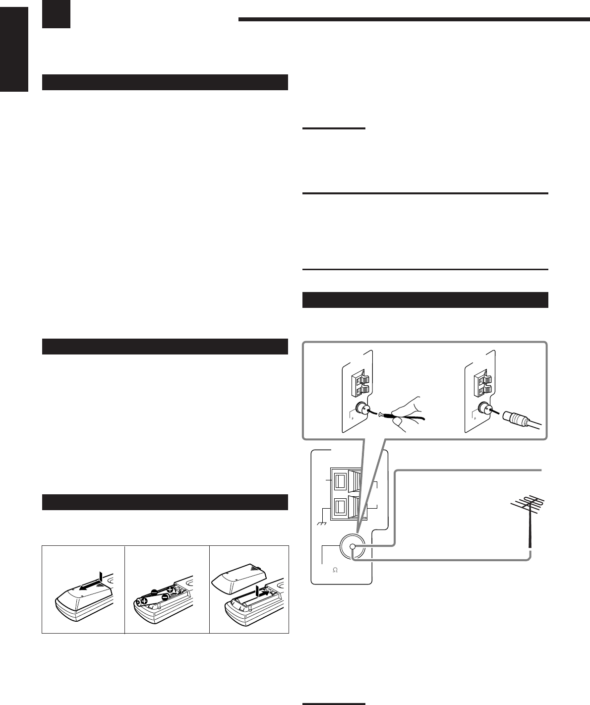
Connecting the FM and AM Antennas
FM Antenna Connections
A. Using the Supplied FM Antenna
The FM antenna provided can be connected to the FM 75 Ω
COAXIAL terminal as temporary measure.
B. Using the Standard Type Connector (Not Supplied)
A standard type connector should be connected to the FM 75 Ω
COAXIAL terminal.
Note:
If reception is poor, connect the outdoor FM antenna (not supplied).
Before attaching a 75
Ω
coaxial cable with a connector (the kind with
a round wire going to an outdoor antenna), disconnect the supplied
FM antenna.
12
R6P(SUM-3)/
AA(15F)
3
01-16_8030&7030[C]7.pm6 03.2.13, 2:51 PM8
9
English
RIGHT LEFT
RIGHT LEFT
RIGHT LEFT
+
–
RIGHT LEFT
AM Antenna Connections
Turn the loop until you have the
best reception.
AM Loop Antenna
(supplied)
Snap the tabs on the loop into the slots
of the base to assemble the AM loop.
Outdoor single vinyl-covered wire (not supplied)
Notes:
•If the AM loop antenna wire is covered with vinyl, remove
the vinyl by twisting it as illustrated.
•Make sure the antenna conductors do not touch any
other terminals, connecting cords and power cord. This
could cause poor reception.
•If reception is poor, connect an outdoor single vinyl-covered wire
(not supplied) to the AM EXT terminal. (Keep the AM loop antenna
connected.)
Connecting the Speakers
You can connect the following speakers:
•Two pairs of front speakers to produce normal stereo sound.
•One pair of surround speakers to enjoy the surround effect.
•One surround back speaker or one pair of surround back speakers
to enjoy to produce more effective surround effect.
•One center speaker to emphasize human voices.
•One subwoofer to enhance the bass.
CAUTION:
Use only the speakers of the SPEAKER IMPEDANCE indicated by
the speaker terminals.
•When connecting to both of the FRONT SPEAKERS 1 and 2
terminals, use speakers with an impedance of 16 Ω to 32 Ω.
•When connecting to either the FRONT SPEAKERS 1 or 2
terminals, use speakers with an impedance of 8 Ω to 16 Ω.
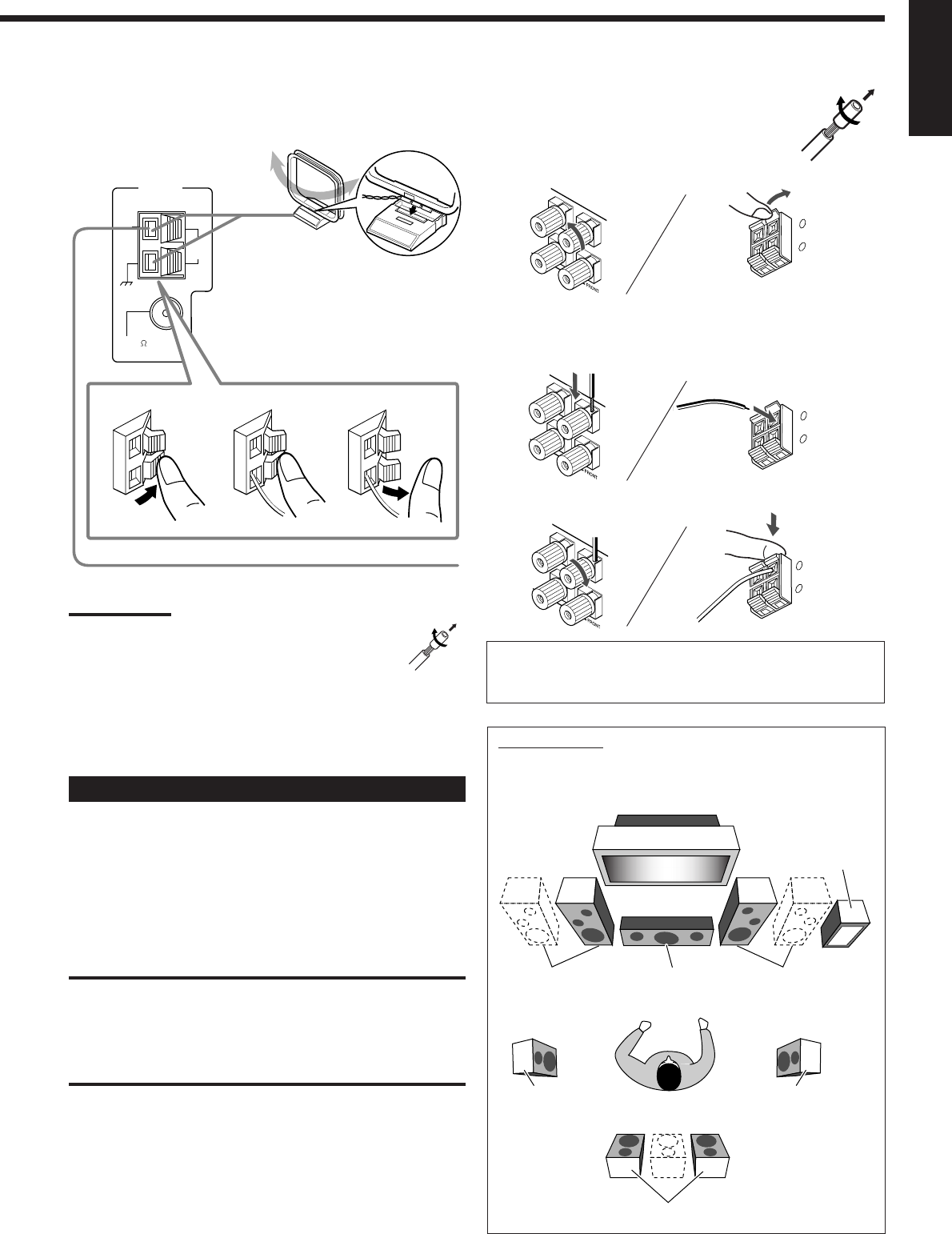
Basic connecting procedure
1 Twist and remove the insulation at
the end of each speaker signal cable
(not supplied).
2 Open the speaker terminal.
RX-7030VBK
(For FRONT SPEAKERS 2 terminals)
3 Insert the speaker signal cable.
4 Close the speaker terminal.
For each speaker (except for a subwoofer), connect the (+) and
(–) terminals on the rear panel to the (+) and (–) terminals
marked on the speakers.
Subwoofer
Speaker layout
Ideal speaker layout varies depending on the conditions of your
listening room. The diagram below is a recommended typical
example.
Left front speaker(s)
(L)
Right front speaker(s)
(R)
Center speaker
(C)
Surround back speakers (LSB/RSB)
Left surround
speaker (LS)
Right surround
speaker (RS)
+
–
RIGHT LEFT
FM 75
COAXIAL
AM
EXT
AM
LOOP
ANTENNA
23
1
+
–
RIGHT LEFT
01-16_8030&7030[C]7.pm6 03.2.13, 2:51 PM9
10
English
Placing speakers
Front speakers and center speaker
•Place these speakers (position of the mid-range speaker units) at the same
height from the floor.
•Point these speakers aiming at the listener’s ears.
Surround and surround back speakers
•Place these speakers at a position which is 1 meter higher than the listener’s
ears.
•Point these speakers down aiming at the listener’s ears.
Subwoofer
•You can place it wherever you like since bass sound is non-directional.
Normally place it in front of you.
Note:
Ideal speaker layout requires that all speakers be placed at the same distance
from the listener. However, since in some places it may be difficult to fulfil this
requirement, this unit can adjust the delay time so that the sounds through all the
speakers reach the listener with the same timing. (See page 28.)
Subwoofer
IMPORTANT:
After connecting the speakers, set the speaker
installation information properly. You can use Quick
Speaker Setup for easy speaker installation information
setting (see page 25).
•To obtain the best possible Surround/DSP effect, see
“Setting the Speakers” on page 27.
Front speakers 1
Right / Left
Surround back speakers*
Right / Left
Front speakers 2
Right / Left
Center speaker
*
When using only one
surround back speaker,
connect the
ª
cord to the
RIGHT
ª
terminal and the
·
cord to the LEFT
·
terminal.
Surround speakers
Right / Left
RIGHT LEFT
+
–
+
–
CENTER
SPEAKER
SURROUNDSPEAKERS
816
CAUTION : SPEAKER IMPEDANCE
SURROUND BACK SPEAKERS
FRONT SPEAKERS
RIGHT LEFT RIGHT LEFT RIGHT LEFT
CAUTION : SPEAKER IMPEDANCE
SINGLE USE
See Instruction
Manual For
Connection
1
OR
2 :
816
1
AND
2 :
16 32
1 2
Connecting the subwoofer speaker
You can enhance the bass by connecting a subwoofer.
Connect the input jack of a powered subwoofer to the rear panel, using a cable with RCA
pin plugs (not supplied).
L
R
L
R
SURR BACK SURR CENTER FRONT
SUBWOOFER
PREOUT
SUBWOOFER
OUT
RX-7030VBK
RX-8030VBK
RIGHT LEFT
+
–
SU
8
CAUTION : SPEAKER IMPEDANCE
SURROUND BACK SPEAKERS
SINGLE USE
See Instruction
Manual For
Connection
C
LR
LS RS
LSB RSB
SB*
* When one surround back speaker is
connected.
•Rear terminals of RX-8030VBK are used for explanation.
01-16_8030&7030[C]7.pm6 03.2.13, 2:51 PM10
11
English
PHONO
IN
RIGHT LEFT
R
L
RX-8030VBK
RX-8030VBK
L
R
L
R
SURR BACK SURR CENTER FRONT
SUBWOOFER
PREOUT
RL
RL
Connecting Audio/Video Components
When connecting individual components, refer also to the manuals
supplied with them.
Analog Connections
If your audio components have digital audio output terminal,
connecting them using the digital cords explained in “Digital
Connections” (see page 16) will give you better sound quality.
Audio component connections
Use the cables with RCA pin plugs (not supplied).
•Connect the white plug to the audio left jack, and the red plug to
the audio right jack.
If your audio components have a COMPU LINK jack
See also page 41 for detailed information about the connection
and the COMPU LINK remote control system.
CAUTION:
If you connect a sound-enhancing device such as a graphic equalizer
between the source components and this receiver, the sound output
through this receiver may be distorted.
Turntable
To listen to the sound after connection, press PHONO.
If a ground cable is
provided for your turntable,
connect the cable to the
screw marked (H) on the
rear.
Note:
This connection is for the turntable with an MM (moving-magnet) type
cartridge.
Any turntables incorporating a small-output cartridge such as an MC
(moving-coil) type must be connected to this receiver through a
commercial head amplifier or step-up transformer. Direct connection
may result in insufficient volume.
Power amplifier
Right front speaker
Power amplifier
Right surround
speaker
Left surround
speaker
Power amplifier
Power amplifier
Center speaker
Enhancing your audio system
—Only for RX-8030VBK
You can use this receiver as the pre-amplifier (control amplifier)
when you connect power amplifiers to the PREOUT jacks on the
rear using cables with RCA pin plugs (not supplied).
•Connect the white plug to the audio left jack, and the red plug to
the audio right jack.
Note:
If you connect one surround back speaker, connect the surround back
speaker to the left surround back PREOUT jack (SURR BACK L).
To audio output
Turntable
RX-8030V
ONLY
RX-8030V
ONLY
Surround back speakers
Left / Right
Left front speaker
01-16_8030&7030[C]7.pm6 03.2.13, 2:51 PM11
12
English
CD player
To listen to the sound after connection, press CD.
Cassette deck
To listen to the sound after connection, press TAPE/MD (for RX-
8030VBK) or TAPE/CDR (for RX-7030VBK).
For RX-8030VBK
You can connect either a cassette deck or an MD recorder to the
TAPE/MD jacks. When connecting an MD recorder, see page 13.
For RX-7030VBK
You can connect either a cassette deck or a CD recorder to the
TAPE/CDR jacks. When connecting an CD recorder to the TAPE/
CDR jacks, see the right column.
CD
IN
R
L
RX-8030VBK/RX-7030VBK
OUT
(REC)
TAPE
MD
IN
(PLAY)
RX-8030VBK
R
L
R
L
CD recorder
To listen to the sound after connection, press CDR (for
RX-8030VBK) or TAPE/CDR (for RX-7030VBK).
For RX-8030VBK
For RX-7030VBK
You can connect either a CD recorder or a cassette deck to the
TAPE/CDR jacks. When connecting a cassette deck to the TAPE/
CDR jacks, see the left column.
Note:
For RX-7030VBK: When connecting a CD recorder to the TAPE/CDR
jacks, change the source name to “CDR,” which will be shown on the
display when it is selected as the source. See page 21 for details.
To audio output
To audio input
Cassette deck
To audio output
To audio input
Cassette deck
RX-7030VBK
TAPE
CDR
IN
(PLAY)
OUT
(REC)
R
L
R
L
RX-8030VBK
OUT
(REC)
CDR
IN
(PLAY)
R
L
R
L
To audio output
To audio input
CD recorder
To audio output
To audio input
CD recorder
To audio
output
CD player
TAPE
CDR
IN
(PLAY)
OUT
(REC)
RX-7030VBK
R
L
R
L
01-16_8030&7030[C]7.pm6 03.2.13, 2:51 PM12
13
English
MD recorder
To listen to the sound after connection, press TAPE/MD (for RX-
8030VBK) or TAPE/CDR (for RX-7030VBK).
For RX-8030VBK
You can connect either an MD recorder or a cassette deck to the
TAPE/MD jacks. When connecting a cassette deck, see page 12.
Note:
When connecting an MD recorder to the TAPE/MD jacks, change the
source name to “MD,” which will be shown on the display when it is
selected as the source. See page 21 for details.
For RX-7030VBK
You can connect an MD recorder to the TAPE/CDR jacks if they are
not used for connecting another component such as a cassette deck
or CD recorder. When connecting an MD recorder to the TAPE/
CDR jacks, see page 12.
•Though your MD recorder is one of JVC products with the
COMPU LINK remote control system, you cannot use the
COMPU LINK remote control system to operate the connected
MD recorder.
OUT
(REC)
TAPE
MD
IN
(PLAY)
RX-8030VBK
R
L
R
L
To audio output
To audio input
MD recorder
Video component connections
Use the cables with RCA pin plugs (not supplied).
Connect the white plug to the audio left jack, the red plug to the
audio right jack, and the yellow plug to the video jack.
•If your video components have S-video (Y/C-separation) and/or
component video (Y, PB, PR) terminals, connect them using an S-
video cable (not supplied) and/or component video cable (not
supplied). By using these jacks, you can get better picture quality
in the order—Component video > S-video > Composite video.
If your video components have an AV COMPULINK jack
See also page 42 for detailed information about the connection
and the AV COMPU LINK remote control system.
IMPORTANT:
This receiver is equipped with the following video jacks—composite
video, S-video and component video jacks. You can use any of the
three to connect a video component.
However, the video signals from one type of these input jacks are
transmitted only through the video output jacks of the same
type.
Therefore, if a recording video component and a playing video
component are connected to the receiver through the video jacks of
different type, you cannot record the picture. In addition, if the TV and
a playing video component are connected to the receiver through the
video jacks of different type, you cannot view the playback picture on
the TV.
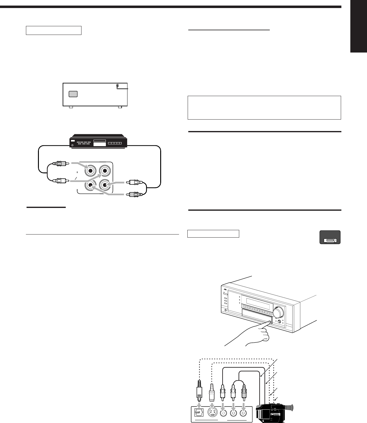
Video camera
To listen to the sound after connection, press VIDEO.
The VIDEO input jacks on the front panel (inside the front door) are
convenient when connecting and disconnecting the component
frequently.
S-VIDEODIGITAL VIDEO L—AUDIO—R
VIDEO
R
L
To composite video
output
To S-video output
To optical digital output
To audio output
Video camera
When using the digital input terminal
Select the digital input mode correctly.
For details, see “Selecting the Analog or Digital Input Mode” on
page 19.
RX-8030V
ONLY
01-16_8030&7030[C]7.pm6 03.2.13, 2:51 PM13
14
English
VCR(s)
To listen to the sound after connection, press VCR 1 or VCR 2 (for
RX-8030VBK) or VCR (for RX-7030VBK).
For RX-8030VBK
You can connect two VCRs—one to the VCR 1 jacks and the other
to the VCR 2 jacks.
•If your VCR has an AV COMPU LINK jack, connect it to the
VCR 1 jack so that you can use the AV COMPU LINK remote
control system.
ÅTo audio input
ıTo audio output
ÇTo S-video output
ÎTo composite video output
‰To S-video input
ÏTo composite video input
For RX-7030VBK
ÅTo audio input
ıTo audio output
ÇTo S-video output
ÎTo composite video output
‰To S-video input
ÏTo composite video input
RX-8030VBK
VCR 2
VCR 1
IN
(PLAY)
IN
(PLAY)
OUT
(REC)
OUT
(REC)
A B DC E F
R
L
R
L
RX-7030VBK
VCR
IN
(PLAY)
OUT
(REC)
A B DC E F
R
L
R
L
TV and/or DBS tuner
To listen to the sound after connection, press TV SOUND/DBS (or
TV/DBS on the remote control).
TV
DBS tuner
ÅTo audio output
ıTo component video input
ÇTo S-video input
ÎTo composite video input
When connecting
the TV to the
AUDIO jacks (TV
SOUND/DBS IN),
DO NOT connect
the TV’s video
output to these
video input jacks.
ÅTo audio output
ıTo component video output
ÇTo S-video output
ÎTo composite video output
Notes:
•When connecting a DBS tuner to the TV SOUND/DBS IN jacks,
change the source name to “DBS,” which will be shown on the
display when selected as the source. Otherwise you cannot view
any picture from DBS tuner. See page 21 for details.
•When connecting a DBS tuner to either one of the component input
jacks, make the component video input setting correctly for AV
CONPU LINK. See page 30 for details.
MONITOR
OUT
TV SOUND
DBS
IN
MONITOR
OUT
YP
B
P
R
A
B
C
D
R
L
RX-8030VBK/RX-7030VBK
Connect the TV to appropriate MONITOR OUT jacks to view
the playback picture from any other connected video
components.
TV SOUND
DBS
IN
DBS
IN
A
B
C
D
R
L
DBS
RX-8030VBK/RX-7030VBK
VCR
VCR
TV
01-16_8030&7030[C]7.pm6 03.2.13, 2:51 PM14
15
English
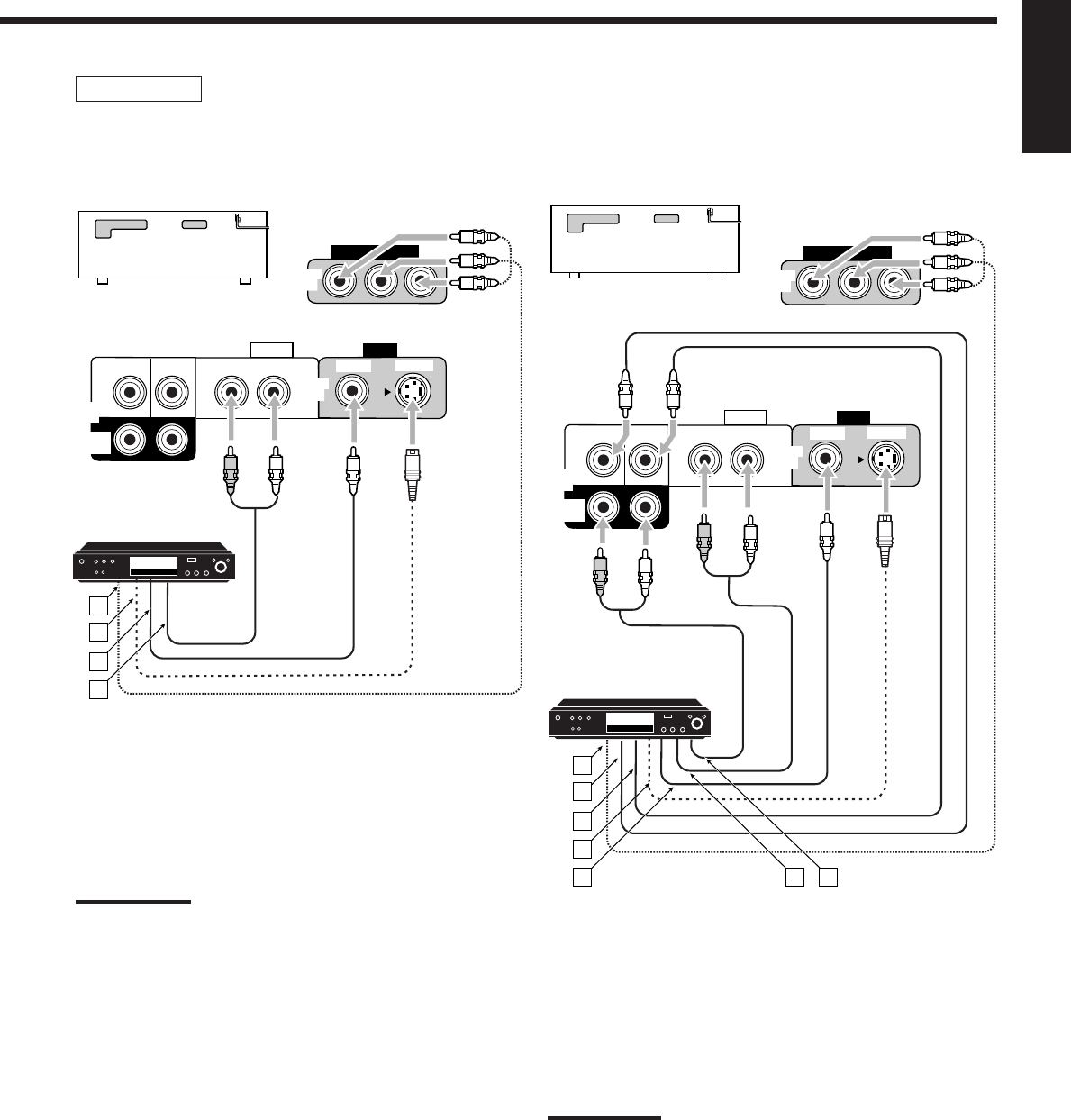
DVD player
• When you connect a DVD player with stereo output jacks:
To listen to the sound after connection, press DVD.
ÅTo component video output
ıTo S-video output
ÇTo composite video output
ÎTo left/right front channel audio output (or to audio-
mixed output if necessary)
Note:
When connecting a DVD player to the component video input jacks,
make the component video input setting correctly for AV COMPU
LINK. See page 30 for details.
DVD player
DVD player
DVD
VIDEO
RIGHT LEFT
S-VIDEO
VIDEO
AUDIO
SUBWOOFER CENTER
DVD
IN
FRONT
DVD
IN
COMPONENT VIDEO
DVD
IN
SURR
(REAR)
RL
A
B
C
D
RX-8030VBK/RX-7030VBK
• When you connect a DVD player with its analog discrete
output (5.1-channel reproduction) jacks:
To listen to the sound after connection, press DVD MULTI.
ÅTo component video output
ıTo subwoofer output
ÇTo center channel audio output
ÎTo S-video output
‰To composite video output
ÏTo left/right front channel audio output
ÌTo left/right surround channel audio output
Note:
When connecting a DVD player to the component video input jacks,
make the component video input setting correctly for AV COMPU
LINK. See page 30 for details.
DVD
VIDEO
RIGHT LEFT
S-VIDEO
VIDEO
AUDIO
SUBWOOFER CENTER
DVD
IN
FRONT
DVD
IN
COMPONENT VIDEO
DVD
IN
SURR
(REAR)
RL
RL
A
B
C
D
E F G
RX-8030VBK/RX-7030VBK
01-16_8030&7030[C]7.pm6 03.2.13, 2:51 PM15
16
English
DIGITAL IN
DIGITAL 1 (DVD)
DIGITAL 2 (CD)
DIGITAL 3 (TV)
DIGITAL 4 (CDR)
PCM/ DOLBY DIGITAL
/ DTS
DIGITAL OUT
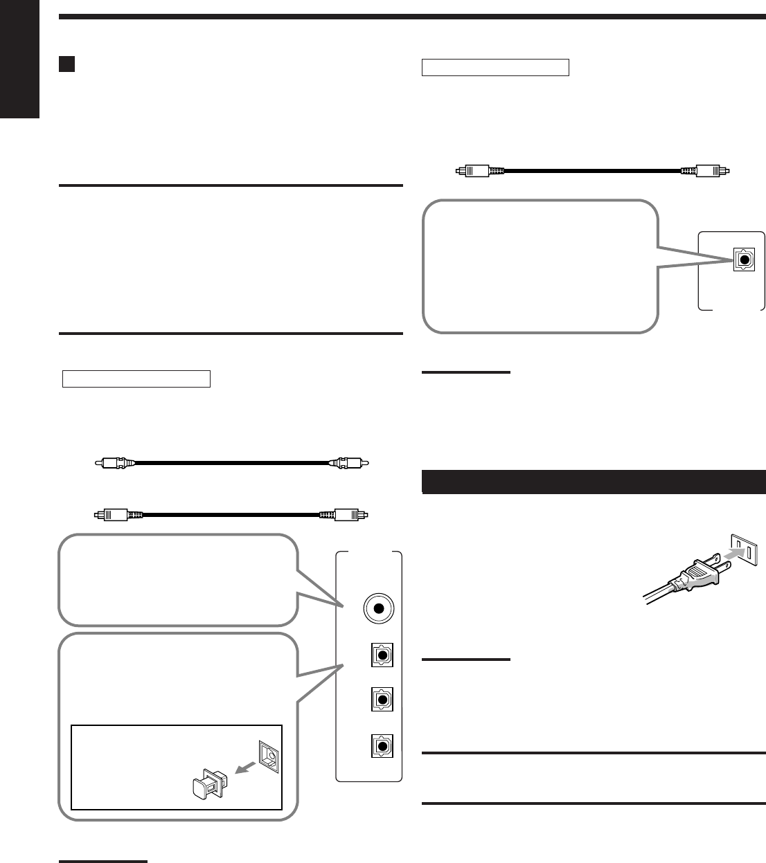
Digital Connections
This receiver is equipped with four DIGITAL IN terminals—one
digital coaxial terminal and three digital optical terminals—and one
DIGITAL OUT (optical) terminal on the rear.
•For RX-8030VBK: Another digital optical input terminal is
located on the front panel (see page 13).
IMPORTANT:
•When connecting a DVD player, digital TV broadcast tuner or DBS
tuner using the digital terminals, you also need to connect it to the
video jacks on the rear. Without connecting it to the video jacks, you
can view no playback picture.
•After connecting the components using the DIGITAL IN terminals,
set the following correctly if necessary.
–Set the digital input (DIGITAL IN) terminal setting correctly. For
details, see “Setting the Digital Input Terminals” on page 29.
–Select the digital input mode correctly. For details, see “Selecting
the Analog or Digital Input Mode” on page 19.
Notes:
•When shipped from the factory, the DIGITAL IN terminals have
been set for use with the following components:
–DIGITAL 1 (coaxial): For DVD player
–DIGITAL 2 (optical): For CD player
–DIGITAL 3 (optical): For digital TV broadcast tuner
–DIGITAL 4 (optical): For CD recorder
•When you want to operate the CD player or CD recorder, (or MD
recorder: only for RX-8030VBK) using the COMPU LINK remote
control system, connect the target component also as described in
“Analog Connections” (see pages 12 and 13).
•When you want to operate a DVD player using the AV COMPU
LINK remote control system (see page 42), connect the DVD
player also as described in “Analog Connections” (see page 15).
Digital input terminals
You can connect any digital components having coaxial or optical
digital output terminal.
Digital output terminal
You can connect any digital components which have an optical
digital input terminal.
Digital coaxial cable (not supplied)
between digital coaxial terminals
Digital optical cable (not supplied)
between digital optical terminals
Before connecting a digital
optical cable, unplug the
protective plug.
When the component has a digital
optical output terminal, connect it to the
DIGITAL 2 (CD), DIGITAL 3 (TV) or
DIGITAL 4 (CDR) terminal, using a
digital optical cable (not supplied).
When the component has a digital
coaxial output terminal, connect it to
the DIGITAL 1 (DVD) terminal, using a
digital coaxial cable (not supplied).
When the digital recording
equipment such as an MD recorder
and CD recorder has a digital
optical input terminal, connecting it
to the DIGITAL OUT terminal
enables you to perform digital-to-
digital recording.
Digital optical cable (not supplied)
between digital optical terminals
Note:
The digital signal format transmitted through the DIGITAL OUT
terminal is the same as that of the input signal. This means that when
the DTS Digital Surround signals are input, the DTS Digital Surround
signals are transmitted.
Connecting the Power Cord
Before plugging the receiver into an AC outlet, make sure that all
connections have been made.
Plug the power cord into an AC outlet.
Keep the power cord away from the
connecting cables and the antenna. The
power cord may cause noise or screen interference.
Note:
The preset settings such as preset channels and sound adjustment
may be erased in a few days in the following cases:
–When you unplug the power cord.
–When a power failure occurs.
CAUTIONS:
•Do not touch the power cord with wet hands.
•Do not pull on the power cord to unplug the cord. When unplugging
the cord, always grasp the plug so as not to damage the cord.
01-16_8030&7030[C]7.pm6 03.2.13, 2:51 PM16
17
English
Basic Operations
The following operations are commonly used when you play any sound sources.
Operations hereafter will be explained using the buttons on the front panel.
You can also use the buttons on the remote control for the same functions if they have the same and similar names/marks.
Selecting the Source to Play
Press one of the source selection buttons.
•The selected source name and the previously selected Surround/
DSP mode also appear on the display.
Selected source name and current
Surround/DSP mode appear.
For RX-8030VBK
•The lamp on the selected source lights up (ex. when DVD is
selected as the source).
For RX-7030VBK
Notes:
•For RX-8030VBK: When connecting an MD recorder (to the TAPE/
MD jack) and a DBS tuner (to the TV SOUND/DBS jacks), change
the source names shown on the display. For details, see page 21.
•For RX-7030VBK: When connecting an CD recorder (to the TAPE/
CDR jacks) and a DBS tuner (to the TV SOUND/DBS jacks),
change the source names shown on the display. For details, see
page 21.
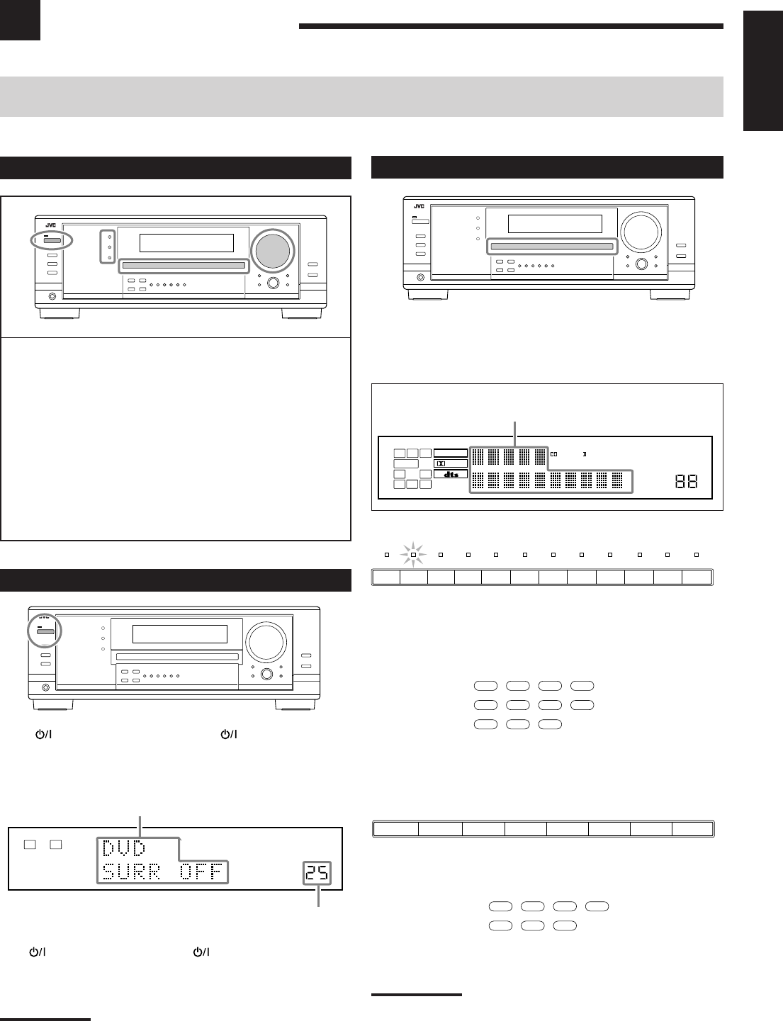
Daily Operational Procedure
1Turn on the power.
•See “Turning On the Power” below.
2Select the source.
•See “Selecting the Source to Play” to the right.
3Adjust the volume.
•See “Adjusting the Volume” on page 18.
4Select the surround or DSP modes.
•See “Activating the Surround Modes” (page 37) and
“Activating the DSP Modes” (page 39).
Turning On the Power
Press STANDBY/ON (or AUDIO on the remote
control).
The STANDBY lamp goes off. The name of the current source and
Surround/DSP mode appear on the display.
Current source name and Surround/DSP mode appear
Current volume level appears.
To turn off the power (into standby mode),
press STANDBY/ON (or AUDIO on the remote control)
again.
The STANDBY lamp lights up.
Note:
A small amount of power is consumed in standby mode. To turn off
the power completely, unplug the AC power cord.
On the unit
On the remote
On the unit
On the remote
DVD MULTI CD
CDR TAPE/MD
TV/DBS VIDEO PHONO
FM/AM
VCR1 VCR2
DVD
DVD MULTI CD
TAPE/CDR
FM/AM
TV/DBS VCR
DVD
TV SOUND/DBSVCR
DVDDVD MULTI AMFMTAPE/CDRCD
13
2
4
VOLUME
LINEAR PCM
LR
ANALOG
SPEAKERS 1
DIGITAL EQ
INPUT ATT
SLEEP
VOLUME
ONE TOUCH OPERATION
3D - PHONIC
NEO:6 VIRTUAL SB MIDNIGHT MODE
AUTO MUTING
TUNED STEREO
LINEAR PCM
DIGITAL
L
SUBWFR
LS RS
CR
S
LFE
DUAL DIGITAL AUTO
ANALOG 96/24 MULTI
PRO LOGIC
DSP
HEADPHONE SPEAKERS 1 2 BASS BOOST
SB
TV SOUND
/DBS
VIDEOVCR 2VCR 1
DVDDVD MULTI AMFMTAPE/MDCDRCDPHONO
17-22_8030&7030[C]7.pm6 03.2.13, 2:51 PM17
18
English
Signal indicators
Speaker indicators
On the unit On the remote
On the unit On the remote
Speaker and signal indicators on the display
By checking the following indicators, you can easily confirm which
speakers you are activating and which signals are coming into this
receiver.
What speaker indicators light depends on the speaker setting
(for details, see “Setting the Speakers” on page 27).
•The frames of “L,” “C,” “R,” “LS,” “RS, ” and “SB” light up,
when the corresponding speakers are set to “LARGE” or
“SMALL” and when the speaker is required for the Surround/DSP
mode currently selected.
•When “SUB WOOFER” is set to “YES,”
SUBWFR
lights up (see
page 27).
•All three frames on the row of “SB” are not used at the same time.
When “SBACK OUT” is set to “2SPK,” the left and the right ones
are used. When it is set to “1SPK,” the middle one is used (see
page 27).
The signal indicators light up to show the incoming signals.
L:•When digital input is selected: Lights up when the left
channel signal comes in.
•When analog input is selected: Always lights up.
R:•When digital input is selected: Lights up when the right
channel signal comes in.
•When analog input is selected: Always lights up.
C: Lights up when the center channel signal comes in.
LFE: Lights up when the LFE channel signal comes in.
LS: Lights up when the left surround channel signal comes in.
RS: Lights up when the right surround channel signal comes in.
S: Lights up when the monaural surround channel signal
comes in.
SB: Lights up when the surround back channel signal comes in.
Note:
When “DVD MULTI” is selected as the source, “L,” “C,” “R,” “LFE,” “LS,”
and “RS” light up.
CD
CDR TAPE/MD
PHONO
FM/AM
AMFMTAPE/CDRCD
CD
TAPE/CDR
FM/AM
Adjusting the Volume
On the front panel:
To increase the volume, turn MASTER VOLUME clockwise.
To decrease the volume, turn it counterclockwise.
From the remote control:
To increase the volume, press VOLUME +.
To decrease the volume, press VOLUME –.
CAUTION:
Always set the volume to the minimum before starting any sources. If
the volume is set at its high level, the sudden blast of sound energy
can permanently damage your hearing and/or ruin your speakers.
Notes:
•The volume level can be adjusted within the range of “0” (minimum)
to “70” (maximum).
•If you set One Touch Operation to “ON” (see page 30), you do not
have to adjust the volume level each time you change the source. It
is automatically set to the stored level.
Selecting different sources for picture and
sound
While watching pictures from a video source, you can listen to
sound of an audio source.
•Once you have selected a video source, pictures of the selected
source are sent to the TV until you select another video source.
Press one of the audio source selection buttons while viewing the
picture from a video component such as the VCR or DVD
player, etc.
For RX-8030VBK
For RX-7030VBK
Note:
When you see the picture through the COMPONENT VIDEO jacks,
you cannot use this function.
AMFMTAPE/MDCDRCDPHONO
Ex. No sound comes out of the
center speaker and surround
back speakers though center
channel and surround back
channel signals are coming
into this receiver.
How to understand the speaker and signal indicator
illumination
SUBWFR
LCR
LS RS
LFE
LCR
SLS
SB
RS
SB
LFE
SUBWFR
LCR
LS RS
SB
17-22_8030&7030[C]7.pm6 03.2.13, 2:51 PM18
19
English
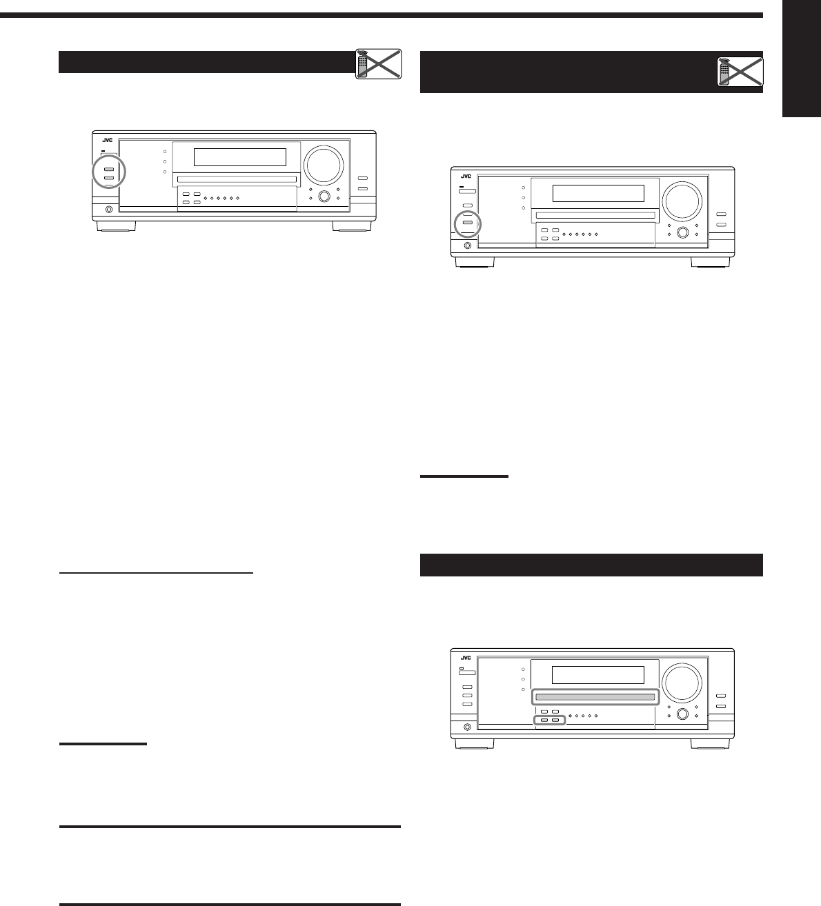
Activating and Adjusting the
Subwoofer Sound
You can cancel the subwoofer sound even though you have
connected a subwoofer and have set “SUB WOOFER” to “YES”
(see page 27). This is useful when enjoying surround sound at night.
Press SUBWOOFER OUT ON/OFF to cancel the subwoofer
sound output.
Each time you press the button, subwoofer sound output is
deactivated (“SUBWFR OFF”) and activated (“SUBWFR ON”)
alternately.
•When subwoofer sound output is activated, subwoofer output level
can be adjusted using the remote control.
1 Press SOUND.
2 Press SUBWOOFER.
3 Press LEVEL + or – to adjust the output level
(–10 dB to +10 dB).
Note:
You cannot deactivate the subwoofer sound output when you set
“SMALL” for the front speakers on the Speaker size setting (see page
27) or Quick Speaker Setup (see page 25).
Listening with headphones only:
Deactivate both sets of the front speakers, and connect headphones
to the PHONES jack.
You can enjoy the sound effects through the headphones when
Surround or DSP mode is activated—3D HEADPHONE
(3D H PHONE) mode.
•“3D H PHONE” appears on the display and the DSP and
HEADPHONE indicator lights up on the display. (For details, see
page 36.)
Note:
When you select “DVD MULTI” as the source or any one of the
Surround/DSP mode which activates the center and/or surround
speaker(s), you can use only one set of the speakers.
CAUTION:
Be sure to turn down the volume:
•Before connecting or putting on headphones, as its high volume can
damage both the headphones and your hearing.
•Before turning on speakers again, as its high volume may come out
of the speakers.
Selecting the Front Speakers
When you have connected two pairs of the front speakers, you can
select which to use.
To use the speakers connected to the FRONT SPEAKERS 1
terminals, press SPEAKERS ON/OFF 1 so that the SPEAKERS 1
indicator lights up on the display. Make sure that the SPEAKERS 2
indicator is not lit on the display.
To use the speakers connected to the FRONT SPEAKERS 2
terminals, press SPEAKERS ON/OFF 2 so that SPEAKERS 2
indicator lights up on the display. Make sure that the SPEAKERS 1
indicator is not lit on the display.
To use both sets of the speakers, press SPEAKERS ON/OFF 1 and
SPEAKERS ON/OFF 2 so that the SPEAKERS 1/2 indicators light
up on the display.
To use neither sets of the speakers, press SPEAKERS ON/OFF 1
and SPEAKERS ON/OFF 2 so that the SPEAKERS 1/2 indicators
go off from the display.
The HEADPHONE indicator lights up and “HEADPHONE”
appears on the display.
•Activating the speakers turns on the Surround and DSP modes
previously selected.
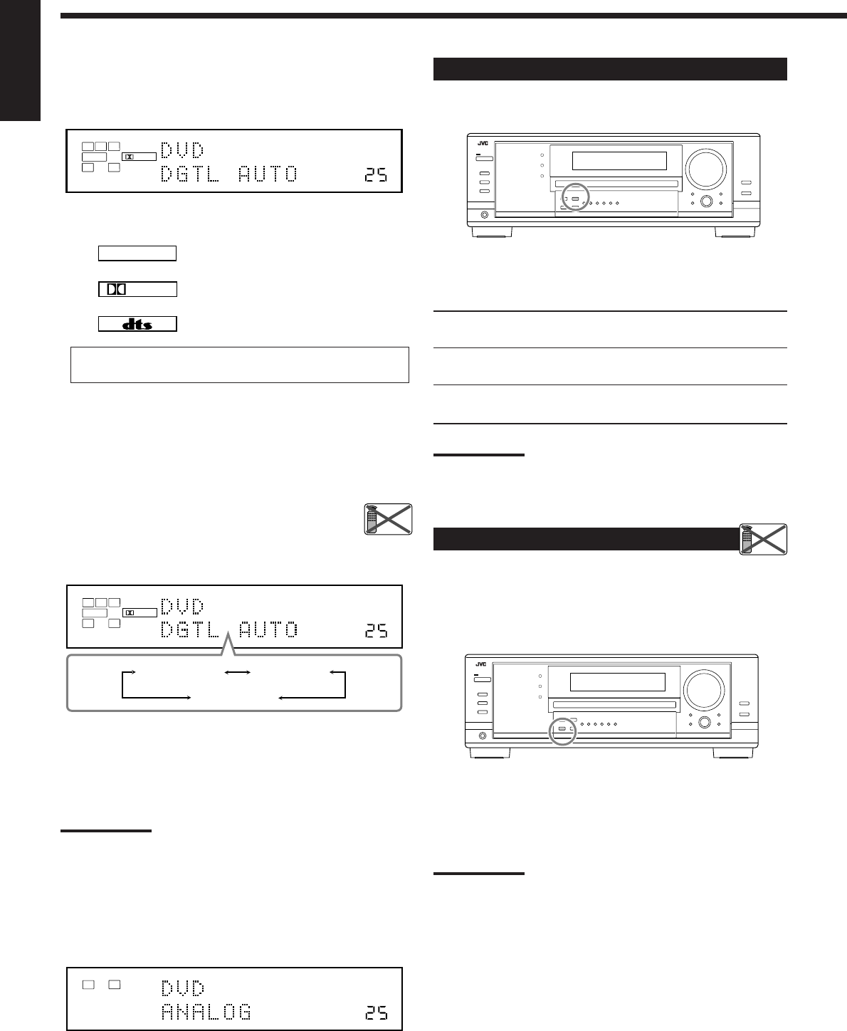
Selecting the Analog or Digital Input Mode
When you have connected digital source components using the
digital terminals (see page 16), change the input mode for these
components to the digital input mode.
Before you start, remember...
The digital input terminal setting should be correctly done for
the sources you want to select the digital input mode (see
“Setting the Digital Input Terminals” on pages 29 and 30).
1. Press one of the source selection buttons for which you
want to change the input mode.
•For RX-8030VBK: DVD, VIDEO, TV (SOUND)/DBS,
CD, CDR, or TAPE/MD*
•For RX-7030VBK: DVD, TV (SOUND)/DBS, CD, or
TAPE/CDR*
*
If “TAPE” is selected as the source, digital input mode is not
available. To change the source name, see “Changing the Source
Name” on page 21.
Continued on the next page
Remote
NOT
Remote
NOT
17-22_8030&7030[C]7.pm6 03.2.13, 2:51 PM19
20
English
LINEAR PCM
DIGITAL
When playing software encoded with the Dolby Digital or DTS,
the following symptoms may occur:
•Sound does not come out at the beginning of playback.
•Noise comes out while searching for or skipping chapters or
tracks.
In this case, press INPUT DIGITAL repeatedly to select
“DGTL D.D” or “DGTL DTS” while “DGTL AUTO”
still remains on the display.
•As you press INPUT DIGITAL, the input mode changes as
follows:
When “DGTL D.D” or “DGTL DTS” is selected, the AUTO
indicator goes off, and the corresponding digital signal format
indicator lights up on the display.
•If the incoming signal does not match the selected digital signal
format, the frame of the selected indicator will flash.
Note:
When you turn off the power or select another source, “DGTL D.D”
and “DGTL DTS” settings are canceled and the digital input mode is
automatically reset to “DGTL AUTO.”
To select the analog input mode again
Press INPUT ANALOG (or press ANALOG/DIGITAL INPUT on
the remote control repeatedly until “ANALOG” appears on the
display). The ANALOG indicator lights up.
2. Press INPUT DIGITAL (or ANALOG/DIGITAL
INPUT on the remote control) to select “DGTL
AUTO.”
The DIGITAL AUTO indicator lights up on the display.
•When selecting “DGTL AUTO,” the following indicators
indicate the digital signal format of the incoming signal.
: Lights up when Linear PCM signals come
in.
: Lights up when Dolby Digital signals
come in.
: Lights up when DTS signals come in.
No indicator lights up when the receiver cannot recognize the
digital signal format of the incoming signals.
VOLUME
DIGITAL
L
SUBWFR
LS RS
CR
LFE
DIGITAL AUTO
SPEAKERS 1
DGTL AUTO DGTL D.D
DGTL DTS
(Dolby Digital)
(Digital)
VOLUME
LINEAR PCM
LR
ANALOG
SPEAKERS 1
VOLUME
DIGITAL
L
SUBWFR
LS RS
CR
LFE
DIGITAL AUTO
SPEAKERS 1
Setting the Dynamic Range
You can enjoy a powerful sound at night using the Midnight Mode.
Press MIDNIGHT MODE so that “MID NIGHT 1” or “MID
NIGHT 2” appears on the display.
The MIDNIGHT MODE indicator also lights up.
MID NIGHT 1: Select when you want to reduce the dynamic
range a little.
MID NIGHT 2: Select when you want to apply the compress
effect fully (useful at midnight).
MID NIGHT OFF: Select when you want to enjoy surround with
its full dynamic range (no effect applied).
Notes:
•If Analog Direct is in use, Midnight Mode is temporarily canceled.
•Midnight Mode is not valid for DVD MULTI playback mode.
Attenuating the Input Signal
When the input level of the analog source is too high, the sounds
will be distorted. If this happens, you need to attenuate the input
signal level to prevent the sound distortion.
•Once you have made adjustment, it is memorized for each analog
source.
Press and hold INPUT ATT (INPUT ANALOG) so that the
INPUT ATT indicator lights up on the display.
•Each time you press and hold the button, the input attenuator
mode turns on (“ATT ON”) or off (“NORMAL”).
Note:
This function is not valid when “DVD MULTI” is selected or when
Analog Direct is activated.
Remote
NOT
Remote
NOT
17-22_8030&7030[C]7.pm6 03.2.13, 2:52 PM20
21
English
Turning Analog Direct On and Off
You can enjoy the sound closer to the original source by overriding
the sound adjustments such as speaker output level adjustments (see
page 32), Digital Equalization (see page 32), Surround and DSP
modes (see pages 34 to 39), Bass Boost (see page 22) and Midnight
Mode (see page 20). You can only adjust the volume level while
Analog Direct is in use.
•Once you have made adjustment, it is memorized for each analog
source.
Press ANALOG DIRECT so that “A DIRECT” appears on the
display.
The lamp on the button also lights up.
•Each time you press the button, Analog Direct turns on and off.
Notes:
•When digital input mode is in use, Analog Direct is not available.
•Turning on Surround or DSP mode cancels Analog Direct and
previously selected sound adjustments are recalled.
•If Analog Direct is in use, Midnight Mode is temporarily canceled.
•Turning on Analog Direct cancels Input Attenuator (page 20) (and
CC Converter for RX-8030VBK: below).
Making Sounds Natural
JVC’s CC (Compensative Compression) Converter eliminates jitter
and ripples, achieving a drastic reduction in digital distortion by
processing the digital music data in 24 bit–quantization and by
expanding the sampling frequency to 128 kHz (for fs 32 kHz
signals)/176.4 kHz (for fs 44.1 kHz signals)/192 kHz (for fs 48 kHz
signals).
By using CC Converter, you can obtain a natural sound field from
both digital and analog sources.
Press CC CONVERTER so that the lamp on the button lights
up.
•Each time you press the button, CC Converter turns on and off (the
lamp goes off) alternately.
Note:
You cannot use this function while Analog Direct is in use. If you turn
on Analog Direct while this function is in use, this function will be
canceled.
Changing the Source Name
When you have connected an MD recorder to the TAPE/MD jacks
or a DBS tuner to the TV SOUND/DBS jacks on the rear panel,
change the source name which will be shown on the display.
When changing the source name from “TV” to “DBS”:
1. Press TV SOUND/DBS.
•Make sure “TV” appears on the display.
2. Press and hold TV SOUND/DBS until “ASSGN DBS”
appears on the display.
Note:
When connecting a DBS tuner to the TV SOUND/DBS IN jacks,
change the source name to “DBS,” which will be shown on the display
when selected as the source. Otherwise you cannot view any picture
from DBS tuner.
For RX-8030VBK:
When changing the source name from “TAPE” to “MD”:
1. Press TAPE/MD.
•Make sure “TAPE” appears on the display.
2. Press and hold TAPE/MD until “ASSGN MD” appears on
the display.
For RX-7030VBK:
When changing the source name from “TAPE” to “CDR”:
1. Press TAPE/CDR.
•Make sure “TAPE” appears on the display.
2. Press and hold TAPE/CDR until “ASSGN CDR” appears on
the display.
To change the source name to “TV” and “TAPE,” repeat the
same procedure above.
Note:
Without changing the source name, you can still use the
connectedcomponents. However, there may be some inconvenience.
•For RX-8030VBK:
–“TAPE” or “TV” will appear on the display when you select the MD
recorder or DBS tuner.
–You cannot use the digital input (see pages 19 and 20) for the
MD recorder.
–You cannot use the COMPU LINK remote control system (see
pages 41) to operate the MD recorder.
•For RX-7030VBK:
–“TAPE” or “TV” will appear on the display when you select the CD
recorder or DBS tuner.
–You cannot use the digital input (see pages 19 and 20) for the
CD recorder.
VOLUME
LINEAR PCM
LR
ANALOG
SPEAKERS 1
RX-8030V
ONLY
Remote
NOT
17-22_8030&7030[C]7.pm6 03.2.13, 2:52 PM21
22
English
The following basic operations are possible only using the
remote control.
Reinforcing the Bass
You can boost the bass level.
•Once you have made adjustment, it is memorized for each source.
1. Press SOUND.
The 10 keys are activated for sound adjustments.
2. Press BASS BOOST to turn on Bass Boost.
The BASS BOOST indicator lights up.
•Each time you press the button, Bass Boost turns on (“BOOST
ON”) and off (“BOOST OFF”) alternately.
For RX-7030VBK:
You can use the BASS BOOST button on the front panel.
When the Bass Boost is activated, the lamp on the button lights up.
•Each time you press the button, Bass Boost turns on and off.
Notes:
•This function affects only the sounds from the front speakers,
center speaker, and subwoofer.
•When Analog Direct is in use (see page 21), the Bass Boost is
canceled temporarily.
Muting the Sound
Press MUTING to mute the sound through all speakers and
headphones connected.
“MUTING” appears on the display and the volume turns off (the
VOLUME level indicator goes off).
To restore the sound, press MUTING again.
•Turning MASTER VOLUME on the front panel or pressing
VOLUME +/– on the remote control also restores the sound.
Changing the Display Brightness
You can dim the display.
Press DIMMER.
•Each time you press the button, the brightness
level of the display change as follows:
Recording a source
For analog-to-analog recording
You can record any analog playback source onto the recording
components connected to the audio output jacks on the rear of
this unit at the same time.
For digital-to-digital recording
You can record the currently selected digital input source through
the receiver to a digital recording device connected to the
DIGITAL OUT terminal.
Notes:
•Analog-to-digital and digital-to-analog recordings are not
possible.
•The output volume level, Midnight Mode (see page 20), Bass
Boost (see the left column), Digital Equalization (see page 32),
Surround modes and DSP modes (see pages 34 to 39) cannot
affect the recording.
Basic adjustment auto memory
This receiver memorizes sound settings for each source—
•when you turn off the power,
•when you change the source, and
•when you assign the source name (see page 21).
When you change the source, the memorized settings for the
newly selected source are automatically recalled.
The following can be stored for each source:
•Analog/digital input mode (see pages 19 and 20)
•Input attenuator mode (see page 20)
•Analog Direct (see page 21)
•Digital Equalization (see page 32)
•Speaker channel output levels (see page 32)
•Surround and DSP mode selection (see pages 37 and 39)
•Bass Boost setting (see the left column)
Notes:
•If the source is FM or AM, you can assign a different setting for
each band.
•If you want to memorize the volume level with the above
settings, set One Touch Operation to “ON” (see page 30).
Using the Sleep Timer
Using the Sleep Timer, you can fall asleep while listening to music.
When the shut-off time comes, the receiver turns off automatically.
Press SLEEP repeatedly.
The SLEEP indicator lights up on the display, and the shut-off time
changes in 10 minutes intervals:
To check or change the time remaining until the shut-off time:
Press SLEEP once.
The remaining time until the shut-off time appears in minutes.
•To change the shut-off time, press SLEEP repeatedly.
To cancel the Sleep Timer:
Press SLEEP repeatedly until “SLEEP 0min” appears on the display.
(The SLEEP indicator goes off.)
•Turning off the power also cancels the Sleep Timer.
231
564
89
7/P
0
+10
BOOST
BASS
MUTING
DIMMER
SLEEP
10/0
SOUND
Reinforcing the
Bass
Using the Sleep
Timer
Muting the
Sound
Changing
the Display
Brightness
2010 30 40 50 60 70 80 90
(Canceled)
0
RX-7030V
ONLY
Dimmer Much dimmer
Canceled
(Normal display)
17-22_8030&7030[C]7.pm6 03.2.13, 2:52 PM22
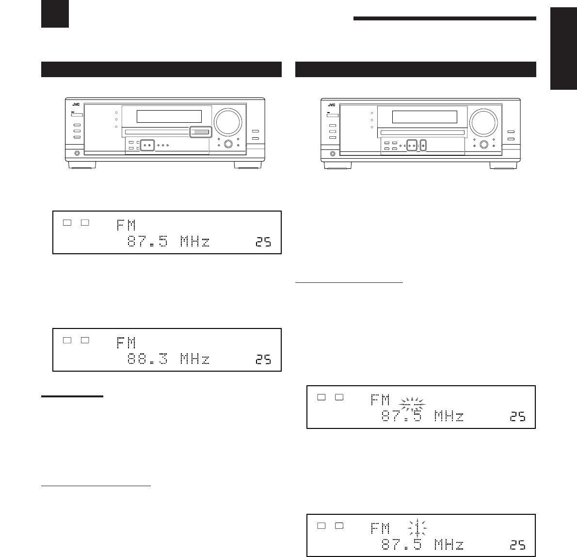
23
English
Receiving Radio Broadcasts
You can browse through all the stations or use the preset function to go immediately to a particular station.
Tuning in to Stations Manually
1. Press FM or AM to select the band.
The last received station of the selected band is tuned in.
2. Press FM/AM TUNING 5 or ∞ repeatedly until
you find the frequency you want.
•Pressing FM/AM TUNING 5 increases the frequency.
•Pressing FM/AM TUNING ∞ decreases the frequency.
Notes:
•When a station of sufficient signal strength is tuned in, the TUNED
indicator lights up on the display.
•When an FM stereo program is received, the STEREO indicator
also lights up.
•When you hold and then release the button in step
2
, the frequency
keeps changing until a station is tuned in.
From the remote control:
1. Press FM/AM.
•Each time you press the button, the band alternates between
FM and AM.
2. Press TUNING UP or TUNING DOWN repeatedly until you
find the frequency you want.
•Pressing TUNING UP increases the frequency.
•Pressing TUNING DOWN decreases the frequency.
VOLUME
TUNED STEREO
LINEAR PCM
LR
ANALOG
SPEAKERS 1
VOLUME
TUNED STEREO
LINEAR PCM
LR
ANALOG
SPEAKERS 1
VOLUME
TUNED STEREO
LINEAR PCM
LR
ANALOG
SPEAKERS 1
VOLUME
TUNED STEREO
LINEAR PCM
LR
ANALOG
SPEAKERS 1
Using Preset Tuning
Once a station is assigned to a channel number, the station can be
quickly tuned in. You can preset up to 30 FM and 15 AM stations.
To store the preset stations
Before you start, remember...
There is a time limit in doing the following steps. If the setting is
canceled before you finish, start from step 2 again.
On the front panel ONLY:
1. Tune in the station you want to preset
(see “Tuning in to Stations Manually”
on the left).
•If you want to store the FM reception mode for this station,
select the FM reception mode you want. See “Selecting the
FM Reception Mode” on page 24.
2. Press MEMORY.
The channel number position starts flashing on the display for
about 10 seconds.
3. Press FM/AM PRESET 5 or ∞ to select a
channel number while the channel number
position is flashing.
4. Press MEMORY again while the selected channel
number is flashing on the display.
The selected channel number stops flashing.
The station is assigned to the selected channel number.
5. Repeat steps 1 to 4 until you store all the stations
you want.
To erase a stored preset station
Storing a new station on a used number erases the previously stored
one
23-24_8030&7030[C]7.pm6 03.2.13, 2:52 PM23
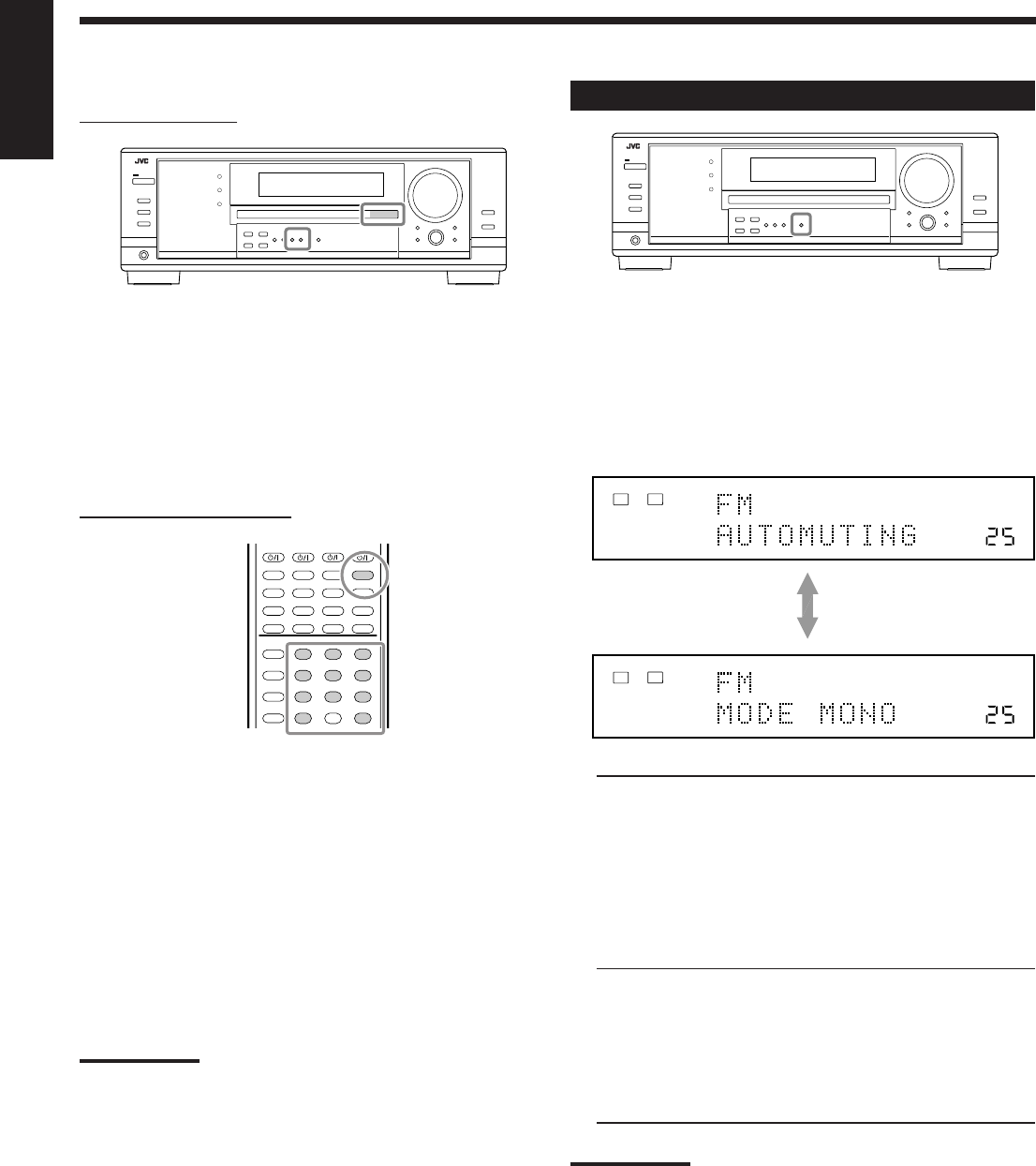
24
English
To tune in a preset station
On the front panel:
1. Press FM or AM to select the band.
The last received station of the selected band is tuned in.
2. Press FM/AM PRESET 5 or ∞ until you find the
channel you want.
•Pressing FM/AM PRESET 5 increases the number.
•Pressing FM/AM PRESET ∞ decreases the number.
From the remote control:
1. Press FM/AM to select the band.
The last received station of the selected band is tuned in.
•Each time you press the button, the band alternates between
FM and AM.
2. Press the 10 keys to select a preset channel
number.
•For channel number 5, press 5.
•For channel number 15, press +10 then 5.
•For channel number 20, press +10 then 10.
•For channel number 30, press +10, +10, then 10.
Note:
When you use the 10 keys on the remote control, be sure that they
are activated for the tuner, not for the CD and others. (See page 44.)
Selecting the FM Reception Mode
When an FM stereo broadcast is hard to receive or noisy, you can
change the FM reception mode while receiving an FM broadcast.
•You can store the FM reception mode for each preset station (see
page 23).
While listening to an FM station, press FM MODE.
•Each time you press the button, the FM reception mode alternates
between “AUTOMUTING” and “MODE MONO.”
AUTOMUTING: Normally select this.
When a program is broadcasted in stereo,
you will hear stereo sound;
when in monaural, you will hear monaural
sounds.
This mode is also useful to suppress static
noise between stations. The AUTO
MUTING indicator lights up on the display.
(Initial setting)
MODE MONO: Select this to improve the reception (but
stereo effect will be lost).
In this mode, you will hear noise while
tuning into the stations. The AUTO
MUTING indicator goes off from the
display. (The STEREO indicator also goes
off.)
Note:
When you use the FM MODE on the remote control, be sure that it is
activated for the tuner, not for the CD and others. (See page 44.)
231
564
89
7/P
0
+10
10/0
VOLUME
AUTO MUTING
TUNED STEREO
LINEAR PCM
LR
ANALOG
SPEAKERS 1
VOLUME
TUNED
LINEAR PCM
LR
ANALOG
SPEAKERS 1
23-24_8030&7030[C]7.pm6 03.2.13, 2:52 PM24
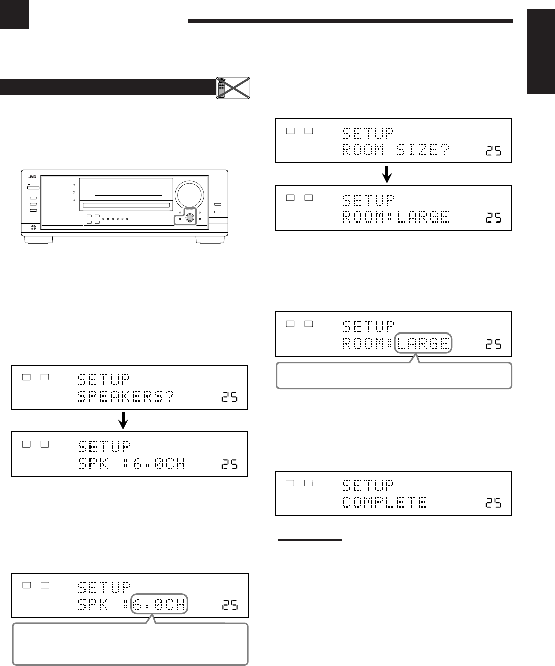
25
English
Setting the Speakers Configuration
Quick Speaker Setup helps you to easily and quickly register the
speaker size and speaker distance according to your listening room
to create the best possible surround effect.
•You can also register each speaker’s information manually.
For details, see page 27.
Before you start, remember...
There is a time limit in doing the following steps. If the setting is
canceled before you finish, start from step 1 again.
On the front panel:
1. Press QUICK SPEAKER SETUP.
“SETUP” and “SPEAKERS?” appear on the display, then the
initial setting for the total number of the connected speakers
(channels) appears.
2. Turn MULTI JOG to select an appropriate
number of the connected speakers (speaker
channel number).
The speaker channel number changes as follows.
•For the details of speaker channel number, see “Speakers
(channels) number and the size” on page 26.
* “6.0CH” is the initial setting.
Basic Settings
Some of the following settings are required after connecting and positioning your speakers while others will make
operations easier. You can use QUICK SPEAKER SETUP to easily set up your speaker configuration.
3. Press in MULTI JOG (PUSH SET).
“ROOM SIZE?” appear on the display, then the initial room size
setting appears.
4. Turn MULTI JOG to select an appropriate room
size to match to your listening room.
The room size changes as follows.
•To select your appropriate room size, see “Room size and the
speaker distance” on page 26.
* “LARGE” is the initial setting.
5. Press in MULTI JOG (PUSH SET).
“COMPLETE” appears on the display, then goes back to the
source indication.
•Speaker configuration settings now become active.
Note:
This procedure will not be completed if you stop in the middle of
the setting process.
Remote
NOT
VOLUME
LINEAR PCM
LR
ANALOG
SPEAKERS 1
VOLUME
LINEAR PCM
LR
ANALOG
SPEAKERS 1
VOLUME
L R
ANALOG
SPEAKERS 1
2.0CH “ 2.1CH “ 3.0CH “ 3.1CH “ 4.0CH “
4.1CH “ 5.0CH “ 5.1CH “ 6.0CH* “ 6.1CH “
7.0CH “ 7.1CH “ (Back to the beginning)
VOLUME
LINEAR PCM
LR
ANALOG
SPEAKERS 1
VOLUME
LINEAR PCM
LR
ANALOG
SPEAKERS 1
VOLUME
LINEAR PCM
LR
ANALOG
SPEAKERS 1
SMALL “ MID “ LARGE* “ (Back to the beginning)
VOLUME
LINEAR PCM
LR
ANALOG
SPEAKERS 1
25-30_8030&7030[C]7.pm6 03.2.13, 2:52 PM25
26
English
Speakers (channels) number and the size
You can find how each of the speaker size is defined according to
the number of connected speakers (speaker channel (CH) number)
you select.
In the following tables, “L” stands for “left front speaker,” “R” for
“right front speaker,” “C” for “center speaker,” “LS” for “left
surround speaker,” “RS” for “right surround speaker,” “SB” for
“surround back speaker,” and “SUBWFR” for “subwoofer.”
•Subwoofer is counted as 0.1 channel.
The size of connected speakers
CH L R C LS RS SB SUBWFR
2.0
LARGE LARGE NONE NONE NONE NONE NO
2.1
SMALL SMALL NONE NONE NONE NONE YES
3.0
LARGE LARGE SMALL NONE NONE NONE NO
3.1
SMALL SMALL SMALL NONE NONE NONE YES
4.0
LARGE LARGE NONE SMALL SMALL NONE NO
4.1
SMALL SMALL NONE SMALL SMALL NONE YES
5.0
LARGE LARGE SMALL SMALL SMALL NONE NO
5.1
SMALL SMALL SMALL SMALL SMALL NONE YES
6.0
LARGE LARGE SMALL SMALL SMALL SMALL NO
6.1
SMALL SMALL SMALL SMALL SMALL SMALL YES
7.0
LARGE LARGE SMALL SMALL SMALL SMALL*NO
7.1
SMALL SMALL SMALL SMALL SMALL SMALL*YES
* This setting is applied to the both speakers.
Room size and the speaker distance
According to the selected room size, speaker distance for each
activated speaker is set as follows:
LARGE Speaker Distance
L 3.0 m (10 ft)
R 3.0 m (10 ft)
C 3.0 m (10 ft)
LS 3.0 m (10 ft)
RS 3.0 m (10 ft)
SB 3.0 m (10 ft)
MID Speaker Distance
L 2.7 m (9 ft)
R 2.7 m (9 ft)
C 2.4 m (8 ft)
LS 2.1 m (7 ft)
RS 2.1 m (7 ft)
SB 1.8 m (6 ft)
SMALL Speaker Distance
L 2.4 m (8 ft)
R 2.4 m (8 ft)
C 2.1 m (7 ft)
LS 1.5 m (5 ft)
RS 1.5 m (5 ft)
SB 1.2 m (4 ft)
Basic Setting Items
On the following pages, you can adjust the following items:
Items To do See page
SUB WOOFER*
1
Register your subwoofer. 27
FRONT SPEAKER*
1
Register your front speaker size. 27
CNTR SPEAKER*
1
Register your center speaker size. 27
SURR SPEAKER*
1
Register your surround speaker size. 27
SBACK SPEAKER*
1
Register your surround back
speaker size. 27
SBACK OUT*
1
Register the number of the
connected surround back speakers. 27
DIST UNIT
Select the measuring unit for the
speaker distance. 28
FRONT DISTANCE*
1
Register the distance from you front
speakers to your listening point. 28
CNTR DISTANCE*
1
Register the distance from you center
speaker to your listening point. 28
SURR DISTANCE*
1
Register the distance from you
surround speakers to your listening
point. 28
SBACK DISTANCE*
1
Register the distance from you
surround back speaker(s) to your
listening point. 28
S WFR OUTPUT
Select sounds emitted from the
subwoofer. 28
CROSS OVER
Select the cutoff frequency to the
subwoofer. 28
LFE ATTENUATE
Attenuate the bass (LFE) sounds. 29
DUAL MONO
Select the Dual Mono sound
channel. 29
DGTL IN COAX
Select the component connected to
digital coaxial terminal 29
DGTL IN OPTICAL*
2
Select the components connected to
digital optical terminals 29
VIDEO IN DVD
Select the type of video terminal
used for the DVD player. 30
VIDEO IN DBS
Select the type of video terminal
used for the DBS tuner. 30
ONE TOUCH OPE
Store the volume level for each
source. 30
Notes:
*
1
These items can be set using Quick Speaker Setup.
*
2
This setting is only for RX-8030VBK.
For RX-7030VBK, it is automatically set according to your “DGTL IN
COAX” setting.
25-30_8030&7030[C]7.pm6 03.2.13, 2:52 PM26
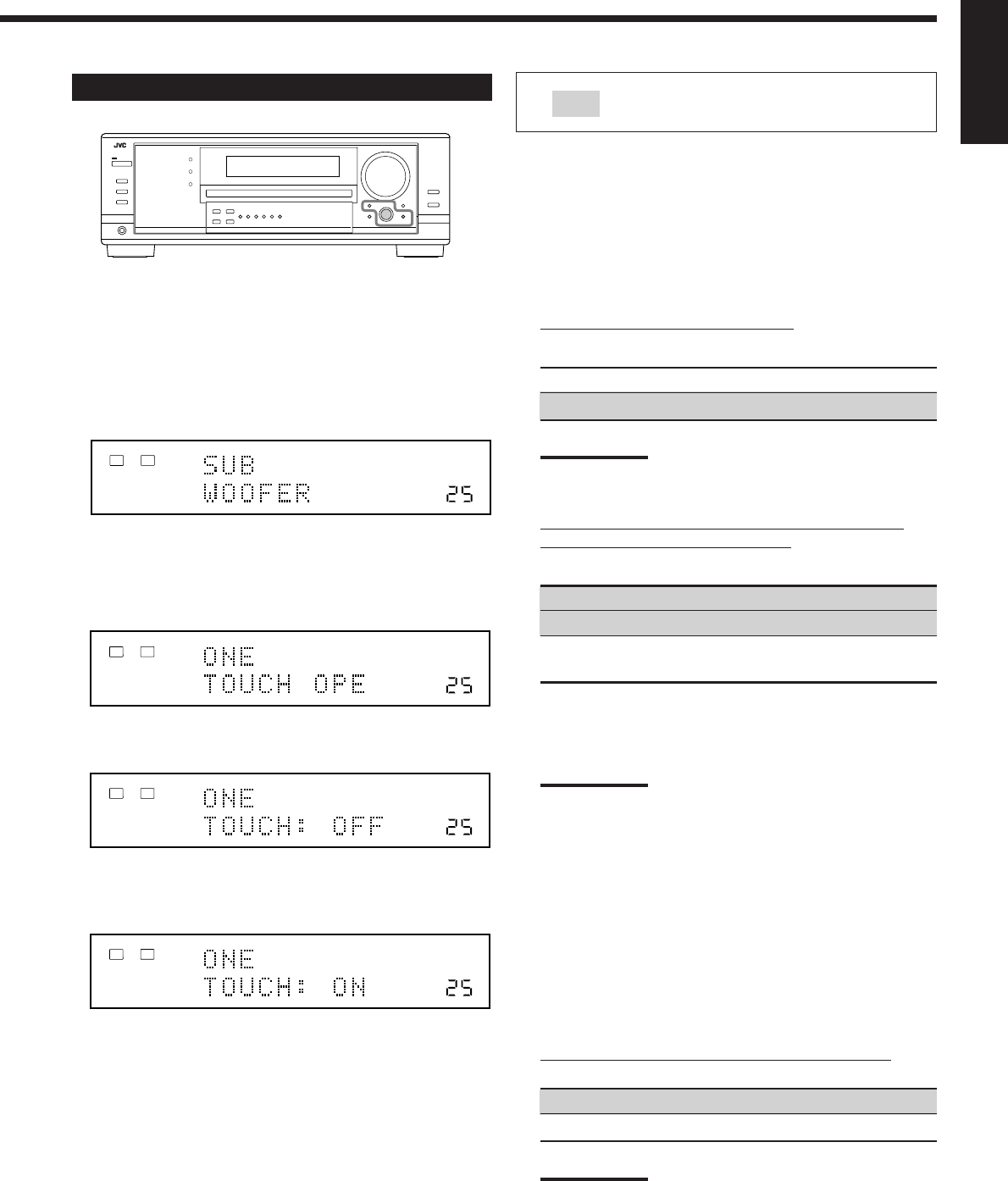
27
English
Basic Procedure
Before you start, remember...
There is a time limit in doing the following steps. If the setting is
canceled before you finish, start from step 1 again.
Ex. When setting One Touch Operation to “ON.”
1. Press SETTING.
The last selected item appears on the display.
2. Turn MULTI JOG until an item you want
appears on the display.
•In this example, select “ONE TOUCH OPE.” For available
items, see the list “Basic Setting Items” on page 26.
3. Push in MULTI JOG (PUSH SET).
The current setting for the selected item appears on the display.
4. Turn MULTI JOG until a setting you want
appears on the display.
5. Press EXIT.
6. Repeat steps 2 to 5 to set other items if necessary.
7. Press EXIT.
The source indication resumes on the display.
Setting the Speakers
To obtain the best possible surround effect from the Surround and
DSP modes, register the setting about the speaker arrangement after
all connections are completed.
•If you have used Quick Speaker Setup on page 25, this setting is
not required.
7
Subwoofer setting—SUB WOOFER
Select whether you have connected a subwoofer or not.
YES: Select when a subwoofer is connected.
NO: Select when no subwoofer is used.
Note:
If you have selected “NO” for the subwoofer, you cannot use the
SUBWOOFER OUT ON/OFF button on the front panel.
7
Speaker size—FRONT SPEAKER, CNTR SPEAKER,
SURR SPEAKER, SBACK SPEAKER
Select the size for each connected speaker.
LARGE*1:Select when the speaker size is relatively large.
SMALL*2:Select when the speaker size is relatively small.
NONE: Select this when you have not connected a
speaker. (Not selectable for the front speakers)
*1Initial setting for front speakers.
*2Initial setting for center, surround, and surround back
speakers.
Notes:
•Keep the following comments in mind as reference when
adjusting.
–If the size of the cone speaker unit built in your speaker is
larger than 12 cm (4
3
/
4
inches), select “LARGE,” and if it is
smaller than 12 cm (4
3
/
4
inches), select “SMALL.”
•If you have selected “NO” for the subwoofer setting, you can
only select “LARGE” for the front speakers.
•If you have selected “SMALL” for the front speakers, you cannot
select “LARGE” for the center, surround, and surround back
speakers.
•If you have selected “SMALL” for the surround speakers, you
cannot select “LARGE” for the surround back speakers.
•If you have selected “NONE” for the surround speakers, the
surround back speakers are fixed to “NONE.”
7
Surround back speakers quantity—SBACK OUT
Select the number of the surround back speakers connected.
1SPK: Select this to use 1 surround back speaker.
2SPK: Select this to use 2 surround back speakers.
Note:
If you have selected “NONE” for the surround back speakers (see
above), this setting is not available.
: shows the initial setting in the following
tables.
VOLUME
LINEAR PCM
LR
ANALOG
SPEAKERS 1
VOLUME
LINEAR PCM
LR
ANALOG
SPEAKERS 1
VOLUME
LINEAR PCM
LR
ANALOG
SPEAKERS 1
VOLUME
ONE TOUCH OPERATION
LINEAR PCM
LR
ANALOG
SPEAKERS 1
25-30_8030&7030[C]7.pm6 03.2.13, 2:52 PM27
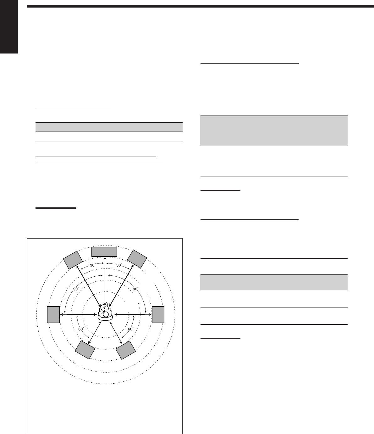
28
English
Setting the Speaker Distance
The distance from your listening point to the speakers is another
important element to obtain the best possible sound of the Surround
and DSP modes. Set the distance from your listening point to the
speakers.
By referring to the speaker distance setting, this unit automatically
sets the delay time of the sound through each speaker so that sounds
through all the speakers can reach you at the same time.
•If you have used Quick Speaker Setup on page 25, this setting is
not required.
7
Measuring unit—DIST UNIT
Select which measuring unit you use.
meter: Select to set the distance in meters.
feet: Select to set the distance in feet.
7
Speaker distance—FRONT DISTANCE, CNTR
DISTANCE, SURR DISTANCE, SBACK DISTANCE
Set the distance from the listening point within the range of
0.3 m (1 ft) to 9.0 m (30 ft), in 0.3 m (1 ft) intervals.
•When shipped from the factory, distance for each speaker is
set to “3.0 m (10 ft).”
Notes:
•You cannot set the speaker distance for the speakers you have
selected “NONE” (see page 27).
•This setting is not valid for the DVD MULTI playback mode.
Ex. In the above case, set the speaker distance as follows:
Front speakers: 3.0 m (10 ft)
Center speakers: 3.0 m (10 ft)
Surround speakers: 2.7 m (9 ft)
Surround back speakers: 2.4 m (8 ft)
Setting the Bass Sounds
You can adjust subwoofer and bass sounds precisely according to
your preference.
7
Subwoofer output—S WFR OUTPUT
You can select the type of the signal which can be transmitted
through the subwoofer. In other words, you can determine
whether or not the bass elements of the front speaker channels
are transmitted through the subwoofer regardless of the front
speaker size setting (either “SMALL” or “LARGE”).
Select one of the following:
LFE: Select to transmit only the LFE signals (while
playing Dolby Digital and DTS software) and
the bass elements of small speakers through the
subwoofer.
LFE+MAIN: Select to always add the bass elements of the
front speaker channels (MAIN) to the above
(LFE) setting, and to transmit them through the
subwoofer.
Note:
If you have selected “NO” for the subwoofer, this function is not
available.
7
Crossover frequency—CROSS OVER
When you use a subwoofer, you can select the cutoff frequency
for the small speakers used.
Select one of the crossover frequency levels according to the
size of the small speaker connected.
80Hz: Select when the cone speaker unit built in the speaker is
about 12 cm (4 3/4 inches).
100Hz: Select when the cone speaker unit built in the speaker is
about 10 cm (3 15/16 inches).
120Hz: Select when the cone speaker unit built in the speaker is
about 8 cm (3 3/16 inches).
150Hz: Select when the cone speaker unit built in the speaker is
about 6 cm (2 3/8 inches).
Notes:
.•If you have selected “LARGE” for all activated speakers (see
page 27), this function is fixed to “OFF.”
•Crossover frequency is not valid for the DVD MULTI playback,
All Channel Stereo, HEADPHONE, and 3D HEADPHONE
mode.
2.1 m
(7 ft)
2.4 m
(8 ft)
2.7 m
(9 ft)
3.0 m
(10 ft)
3.3 m
(11 ft)
C
LR
LS RS
LSB RSB
25-30_8030&7030[C]7.pm6 03.2.13, 2:52 PM28
29
English
7
Low frequency effect attenuator—LFE ATTENUATE
If the bass sound is distorted while playing back software
encoded with Dolby Digital or DTS, set the LFE level to
eliminate distortion.
Select one of the following:
0dB: Normally select this.
−−
−−
−10dB: Select when the bass sound is distorted.
Selecting main or sub channel—DUAL MONO
Select the playback sounds (channel).
MAIN: Select to play back the main channel (Ch1).*1
Signal indicator “L” lights up while playing back this
channel.
SUB: Select to play back the sub-channel (Ch2).*1
Signal indicator “R” lights up while playing back this
channel.
ALL: Select to play back both the main and sub-channels
(Ch1/Ch2).*1
Signal indicators “L” and “R” light up while playing
back these channels.
Notes:
•The Dual Mono format is not identical with bilingual
broadcasting or the MTS (Multichannel Television Sound)
format used for TV programs. So this setting does not take
effect while watching bilingual or MTS programs.
*1
Dual Mono signals can be heard from the following speakers—
L (left front speaker), R (right front speaker), and C (center
speaker)—with respect to the current Surround setting.
With Surround Activated
Dual Mono Without Surround Center speaker setting
Setting SMALL/LARGE NONE
LRLCRL R
MAIN Ch 1 Ch 1 — Ch 1 — Ch 1 Ch1
SUB Ch 2 Ch 2 — Ch 2 — Ch 2 Ch 2
ALL Ch 1 Ch 2 — Ch 1+Ch 2 — Ch 1+Ch 2 Ch 1+Ch 2
Setting the Digital Input Terminals
When you use the digital input terminals, register which components
you have connected to the digital input terminals.
7
Digital coaxial terminal—DGTL IN COAX
Set the component connected to the digital coaxial terminal
(DIGITAL IN 1).
•For RX-8030VBK: DVD (initial setting), MD*, CDR, TV (or
DBS**) or CD.
•For RX-7030VBK: DVD (initial setting), CD, TV (or DBS**)
or CDR.
7
Digital optical terminals—DGTL IN OPTICAL
For RX-8030VBK:
Set the components connected to the digital optical terminals
(DIGITAL IN 2 – 4).
•As you rotate MULTI JOG, the digital optical input terminals
are set to used for following digital components:
When “DIGITAL IN 1 (DGTL IN COAX)” is set to “DVD”
2: CD 3: TV (or DBS** ) 4: CDR “
2: CD 3: TV (or DBS**) 4: MD* “
2: CD 3: MD* 4: CDR “
2: MD* 3: TV (or DBS** ) 4: CDR “
(back to the beginning)
When “DIGITAL IN 1 (DGTL IN COAX)” is set to “CD”
2: DVD 3: TV (or DBS**) 4: CDR “
2: DVD 3: TV (or DBS**) 4: MD* “
2: DVD 3: MD* 4: CDR “
2: MD* 3: TV (or DBS**) 4: CDR “
(back to the beginning)
When “DIGITAL IN 1 (DGTL IN COAX)” is set to “TV” or
“DBS”**
2: CD 3: DVD 4: CDR “
2: CD 3: DVD 4: MD* “
2: CD 3: MD* 4: CDR “
2: MD* 3: DVD 4: CDR “
(back to the beginning)
When “DIGITAL IN 1 (DGTL IN COAX)” is set to “CDR”
2: CD 3: TV (or DBS**) 4: DVD “
2: CD 3: TV (or DBS**) 4: MD* “
2: CD 3: MD* 4: DVD “
2: MD* 3: TV (or DBS**) 4: DVD “
(back to the beginning)
When “DIGITAL IN 1 (DGTL IN COAX)” is set to “MD”*
2: CD 3: TV (or DBS**) 4: CDR “
2: CD 3: TV (or DBS**) 4: DVD “
2: CD 3: DVD 4: CDR “
2: DVD 3: TV (or DBS**) 4: CDR “
(back to the beginning)
*
When connecting an MD recorder to the digital input terminal,
change the source name to “MD” from “TAPE” (see page 21).
**
If you have changed the source name from “TV” to “DBS,”
“DBS” appears (see page 21).
25-30_8030&7030[C]7.pm6 03.2.13, 2:52 PM29
30
English
Memorizing the Volume Level for Each Source
This unit memorizes some settings separately for each source.
In addition, you can store the volume level for each source with the
other memorized settings—One Touch Operation.
7
One Touch Operation—ONE TOUCH OPE
Select one of the following:
ON: Select to store the volume level separately for each
source. (The ONE TOUCH OPERATION indicator lights
up on the display.)
This receiver memorizes the volume level—
•when you change the source, or
•when you change the source name.
OFF: Select this not to store the volume level.
To recall the volume level
With the ONE TOUCH OPERATION indicator lit, the volume
level for the currently selected source is recalled when the
source is selected.
To cancel the One Touch Operation
Set One Touch Operation to “OFF” so that the ONE TOUCH
OPERATION indicator goes off.
For RX-7030VBK:
As you set the components connected to the digital coaxial
terminal (DIGITAL IN 1), the optical terminals (DIGITAL IN 2
– 4) will be automatically fixed to connect the components listed
below.
When “DIGITAL IN 1 (DGTL IN COAX)” is set to “DVD”
2: CD 3: TV (or DBS*) 4: CDR
When “DIGITAL IN 1 (DGTL IN COAX)” is set to “CD”
2: DVD 3: TV (or DBS*) 4: CDR
When “DIGITAL IN 1 (DGTL IN COAX)” is set to “TV” or
“DBS”*
2: DVD 3: CD 4: CDR
When “DIGITAL IN 1 (DGTL IN COAX)” is set to “CDR”
2: DVD 3: CD 4: TV (or DBS*)
*
If you have changed the source name from “TV” to “DBS,”
“DBS” appears (see page 21).
Setting the Component Video Input
When you use the component video inputs for connecting the DVD
player and/or DBS tuner, register the type of input jacks.
If you have not selected appropriate video input jacks, the AV
COMPU LINK remote control system cannot operate properly. (See
page 42.)
7
For the DVD player—VIDEO IN DVD
Select one of the following:
COMPNT: Select when connecting the DVD player to the
component video input jacks.
S/C: Select when connecting the DVD player to the
composite video or S-video input jacks.
7
For the DBS tuner—VIDEO IN DBS
Select one of the following:
COMPNT: Select when connecting the DBS tuner to the
component video input jacks.
S/C: Select when connecting the DBS tuner to the
composite video or S-video input jacks.
25-30_8030&7030[C]7.pm6 03.2.13, 2:52 PM30
31
English
Adjusting Sound
You can make sound adjustment to your preference after completing basic setting.
Basic Procedure
Before you start, remember...
There is a time limit in doing the following steps. If the setting is
canceled before you finish, start from step 1 again.
Ex. When adjusting the subwoofer level to “– 3”.
1. Press ADJUST.
The last selected item appears on the display.
2. Turn MULTI JOG until an item you want
appears on the display.
•In this example, select “SUBWFR LVL.” For available items,
see the list to the left.
3. Press in MULTI JOG (PUSH SET).
The current setting (or level) for the selected item appears on the
display.
4. Turn MULTI JOG to select a setting you want or
to make an adjustment as you like.
5. Press EXIT.
6. Repeat steps 2 to 5 to set other items if necessary.
7. Press EXIT.
The source indication resumes on the display.
Basic Setting Items
On the following pages, you can adjust the items listed below:
•You can adjust only the items applicable to the current sound
mode.
•If Analog Direct is in use, you cannot make any sound
adjustments.
Items To do See page
DIGITAL EQ Adjust equalizer pattern. 32
SUBWFR LVL Adjust the subwoofer output level. 32
FRONT L LVL Adjust the left front speaker output
level. 32
FRONT R LVL Adjust the right front speaker output
level. 32
CENTER LVL Adjust the center speaker output
level. 32
SURR L LVL Adjust the left surround speaker
output level. 32
SURR R LVL Adjust the right surround speaker
output level. 32
SBACK LVL Adjust the surround back speaker
output level. 32
EFFECT*1Adjust the DAP effect level. 33
ROOMSIZE*1Select the room size for your virtual
listening room. 33
LIVENESS*1Select the liveness level for your
virtual listening room. 33
CTR TONE Make the center tone soft or sharp. 33
PANORAMA*2Add “wraparound” sound effect with
side-wall image. 33
CNTR WIDTH*2Adjust the center channel localization
between the center speaker and the
left/right front speakers. 33
DIMENSION*2Adjust sound localization position. 33
CNTR GAIN*3Adjust sound localization of the
center channel. 33
Notes:
*
1
Adjustable when the DAP mode is in use.
*
2
Adjustable when Pro Logic II Music is in use.
*
3
Adjustable when Neo:6 Music is in use.
VOLUME
LINEAR PCM
L
SUBWFR
R
ANALOG
SPEAKERS 1
VOLUME
LINEAR PCM
L
SUBWFR
R
ANALOG
SPEAKERS 1
VOLUME
LINEAR PCM
L
SUBWFR
R
ANALOG
SPEAKERS 1
VOLUME
LINEAR PCM
L
SUBWFR
R
ANALOG
SPEAKERS 1
31-33_8030&7030[C]7.pm6 03.2.13, 2:52 PM31
32
English
Adjusting the Speaker Output Levels
You can adjust the speaker output levels. The test tone comes out of
each speaker except subwoofer to check the output level balance
when using the Surround mode.
•Once you have made an adjustment, it is memorized for each
source.
7
Adjustable speakers
You can adjust the following speakers’ output levels within the
range of –10 dB to +10 dB (“0 dB” is the initial setting):
SUBWFR LVL
:Select to adjust the subwoofer output level.
FRONT L LVL: Select to adjust the left front speaker
output level.
FRONT R LVL: Select to adjust the right front speaker
output level.
CENTER LVL: Select to adjust the center speaker output
level.
SURR L LVL: Select to adjust the left surround speaker
output level.
SURR R LVL: Select to adjust the right surround speaker
output level.
SBACK LVL: Select to adjust the surround back speaker
output level.
Notes:
•If you have selected “NO” or “NONE” for a speaker (see page
27), the output level for the corresponding speaker is not
adjustable.
•The center speaker, and left/right surround speakers’ output
levels are adjustable for DVD MULTI playback mode, even
though “NONE” is selected for the speaker settings.
•Speaker output levels (except the subwoofer output level) are
not adjustable when Analog Direct is in use. To adjust
subwoofer output level, see page 19.
Adjusting the Equalization Patterns
You can adjust the equalization patterns to your preference.
•Once you have made adjustment, it is memorized for each source.
7
Equalization adjustment—DIGITAL EQ
You can adjust five frequency (63 Hz, 250 Hz, 1 kHz,
4 kHz, 16 kHz) within the range of –8 dB to +8 dB (“0 dB” is
the initial setting) in 2 dB steps.
•When adjustment is made, the DIGITAL EQ indicator lights
up on the display.
To flat the equalization pattern, set all the frequency to “0 dB”
in step 4 of “Basic Procedure” (on page 31). The DIGITAL EQ
indicator goes off from the display.
Notes:
•When Analog Direct is in use, Digital Equalization patterns are not
available.
•The Digital Equalization affects the front speaker sounds only.
You can also use the remote control for equalization adjustment.
1. Press SOUND.
The 10 keys are activated for sound adjustments.
2. Press DIGITAL EQ (Equalization) repeatedly to select
the center frequency you want to adjust.
•Each time you press the button, the center frequency with
its current level appear on the display
3. Press LEVEL + or – repeatedly to adjust the level of the
center frequency.
The DIGITAL EQ indicator lights up on the display.
•The frequency level changes from –8 dB to +8 dB in 2 dB
steps.
4. Repeat steps 2 and 3 to adjust the other center
frequency.
231
564
89
7/P
0
+10
10/0
31-33_8030&7030[C]7.pm6 03.2.13, 2:52 PM32
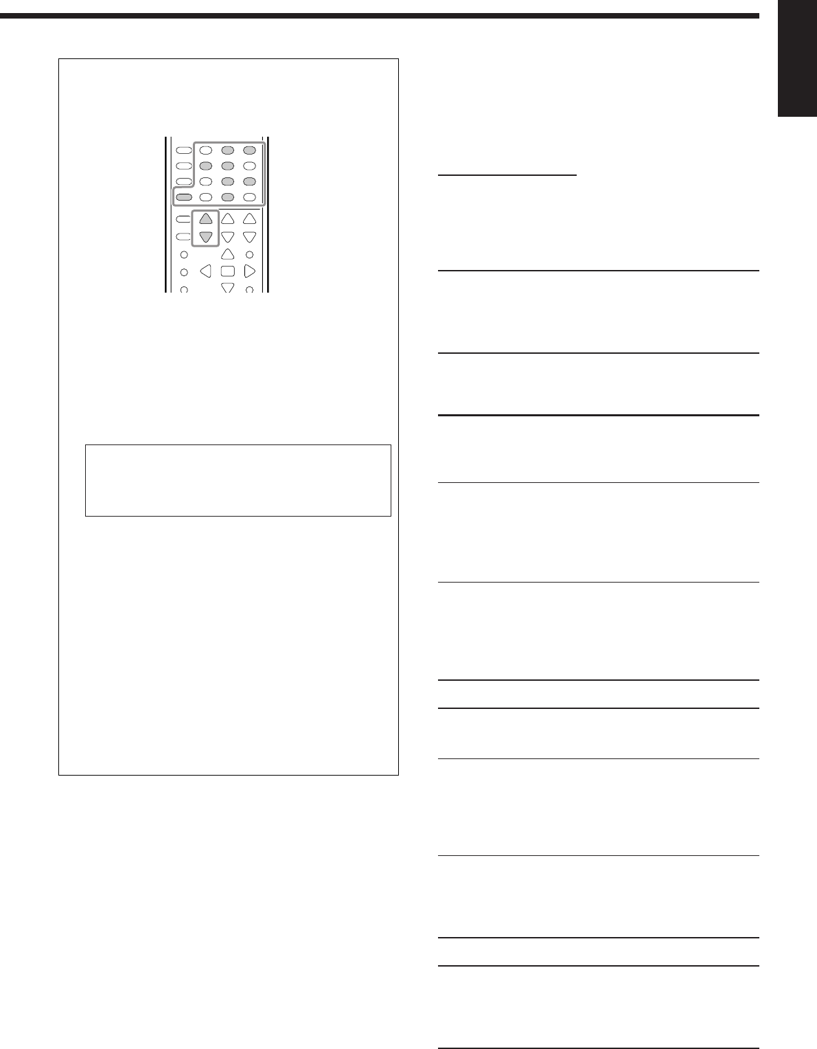
33
English
You can also use the remote control for adjusting the speaker
output level.
When using the remote control, you can make an adjustment
while listening to test tone.
1. Press SOUND.
The 10 keys are activated for sound adjustments.
2. Press TEST to check if you can hear the sounds through
all the speakers at equal level.
Test tone comes out of the speakers in the following order.
•No test tone comes out of the deactivated speakers and the
subwoofer.
FRNT L (Left front speaker)
=
CENTER (Center speaker)
=
FRNT R (Right front speaker)
=
SURR R (Right surround speaker)
=
S BACK (surround back speaker)
=
SURR L (Left surround speaker)
=
(Back to the beginning)
3. Select a speaker you want to adjust.
•To select the left front speaker, press FRONT•L.
•To select the center speaker, press CENTER.
•To select the right front speaker, press FRONT•R.
•To select the right surround speaker, press SURR•R.
•To select the surround back speaker, press SURR BACK.
•To select the left surround speaker, press SURR•L.
4. Press LEVEL + or LEVEL – to adjust the speaker
output level (–10 dB to +10 dB).
5. Repeat steps 3 and 4 to adjust the other speaker’s output
levels.
6. Press TEST again to stop the test tone.
231
564
89
7/P
0
+10
10/0
Adjusting the Sound Parameters for the
Surround and DSP Modes
You can adjust the Surround and DSP sound parameters to your
preference.
•When center speaker is set to “NONE,” CTR TONE, CNTR
WIDTH, and CNTR GAIN are not available.
7
Adjustable parameters
You can adjust the following parameters:
For Surround, DAP, and All Channel Stereo modes (when the
center speaker is connected)
•This setting is common to all surround modes, and is
memorized separately for DSP modes.
CTR TONE: Adjust the center tone. As the number increases,
the dialogue becomes clearer so that the human
voices change from soft to sharp.
(Normally select “3 (initial setting).” Adjustable
range: 1 to 5)
For DAP modes
•Once you have made an adjustment, it is memorized for each
DAP mode.
EFFECT: Adjust the DAP effect level. As the number
increases, the DAP effect becomes stronger.
(Normally select “3 (initial setting).”
Adjustable range: 1 to 5)
ROOMSIZE: Adjust the virtual room size. As the number
increases, the interval between reflections
increases so that you will feel as if you were
in a larger room.
(Normally select “3 (initial setting).”
Adjustable range: 1 to 5)
LIVENESS: Adjust the liveness effect. As the number
increases, the attenuation level of reflections
over time decreases so that acoustics change
from “Dead” to “Live.”
(Normally select “3 (initial setting).” Adjustable
range: 1 to 5)
For Pro Logic II Music only
PANORAMA: Select “ON” to add “wraparound” sound
effect with side-wall image. (Initial setting:
“OFF”)
CNTR WIDTH: Adjust the center channel localization between
the center speaker and the left/right speakers.
As the number increases, the center channel
sound moves toward the left and right
speakers. (Normally select “3 (initial setting).”
Adjustable range: OFF and 1 to 7)
DIMENSION: Adjust sound localization position. As the
number increases, the sound localization
moves towards forward from backward.
(Normally select “4 (initial setting).” Adjustable
range: 1 to 7)
For Neo:6 Music only
CNTR GAIN: Adjust the sound localization of the center
channel. As the number increases, center
channel will be localized clearly.
(Normally select “0.2 (initial setting).”
Adjustable range: 0 to 0.5)
31-33_8030&7030[C]7.pm6 03.2.13, 2:52 PM33
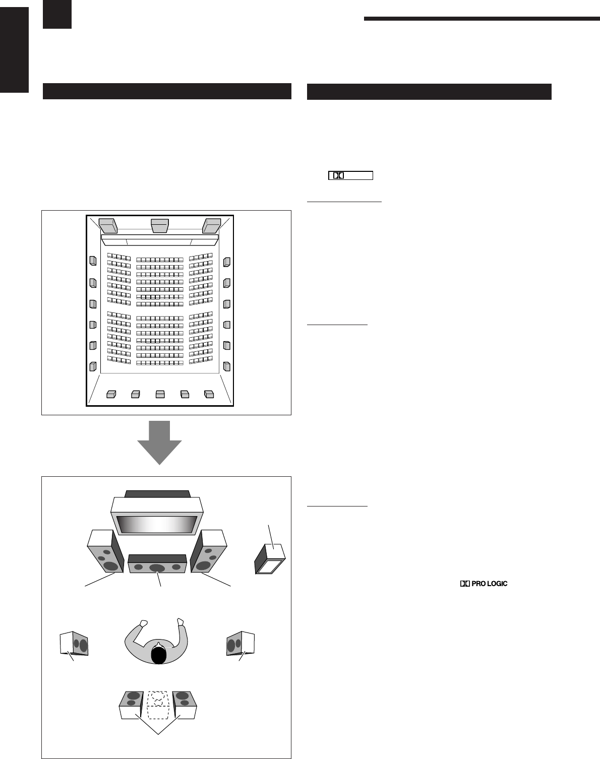
34
English
Using the Surround Modes
This unit activates a variety of Surround modes automatically. The basic settings and adjustments stored (see pages
25 to 33) are applied.
Reproducing Theater Ambience
In a movie theater, many speakers are located on the walls to
reproduce impressive multi-surround sounds, reaching you from all
directions.
With these many speakers, sound localization and sound movement
can be expressed.
Surround modes built in this receiver can create almost the same
surround sounds as you can feel in a real movie theater—with only
five to seven speakers (plus subwoofer).
Introducing the Surround Modes
Dolby Digital*1
Dolby Digital is a digital signal compression method, developed
by Dolby Laboratories, and enables multi-channel encoding and
decoding (1ch up to 5.1ch).
•When Dolby Digital signal is detected through the digital input,
the
DIGITAL
indicator lights up on the display.
Dolby Digital 5.1CH
Dolby Digital 5.1CH (DOLBY D) encoding method records and
digitally compresses the left front channel, right front channel,
center channel, left surround channel, right surround channel, and
LFE channel signals (total 6 channels, but the LFE channel is
counted as 0.1 channel. Therefore, called 5.1 channel).
Dolby Digital enables stereo surround sounds, and sets the cutoff
frequency of the surround treble at 20 kHz, compared to 7 kHz for
Dolby Pro Logic. As such, the sound movement and “being-there”
feeling are enhanced much more than Dolby Pro Logic.
Dolby Digital EX
Dolby Digital EX (DOLBY D EX) is a digital surround encoding
format that adds the third surround channels, called “surround
back.”
Compared to the conventional Dolby Digital 5.1CH, these newly
added surround back channels can reproduce more detailed
movements behind you while viewing the video software. In
addition, surround sound localization will become more stable.
•You can use Virtual 6.1-channel surround when playing back
Dolby Digital EX software without connecting the surround
back speakers. This surround reallocates the surround back
channel to the surround speakers so that you can still feel the
great surround effect from behind.
The VIRTUAL SB (Surround Back) indicator lights up on the
display.
Dolby Pro Logic
Dolby Surround encoding format records the left front channel,
right front channel, center channel, and surround channel
(monaural) signals into 2 channels.
The Dolby Pro Logic (PRO LOGIC) decoder built in this receiver
decodes these 2 channel signals into 4 original channel signals
(plus subwoofer)—matrix-based multi-channel reproduction.
•When Dolby Pro Logic is activated, the indicator
lights up on the display.
Subwoofer
Left front speaker
(L)
Right front speaker
(R)
Center speaker
(C)
Surround back speakers (LSB/RSB)
Left surround
speaker (LS)
Right surround
speaker (RS)
34-40_8030&7030[C]7.pm6 03.2.13, 2:52 PM34
35
English
DTS 96/24
In recent years, there has been increasing interest in higher sampling
rates both for recording and for reproducing at home. Higher
sampling rates allow wider frequency range and greater bit depths
provide extended dynamic range.
DTS 96/24 is a multi-channel digital signal format (fs 96 kHz/24
bits) introduced by Digital Theater Systems, Inc. to deliver “better-
than-CD sound quality” into the home.
•When DTS 96/24 signal is detected, the 96/24 indicator lights up.
You can enjoy its 5.1-channel sound with full-quality.
DTS Neo:6
DTS Neo:6 is another conversion method to create 6-channel (plus
subwoofer) from analog/digital 2-channel software by using the high
precision digital matrix decoder used for DTS-ES Matrix 6.1ch.
When one of Neo:6 modes is activated, the NEO:6 indicator lights
up on the display.
•This receiver provides the following DTS NEO:6 modes—Neo:6
Cinema (NEO:6CINMA) and Neo:6 Music (NEO:6MUSIC).
NEO:6CINMA: Suitable for playing movies. You can get the
same atmosphere with 2-channel software as
with 6.1-channel software. It is also effective for
playing software encoded with conventional
surround formats.
NEO:6MUSIC: Suitable for playing music software. The front
channel signals bypass the decoder (resulting in
no loss of sound quality) and the surround
signals transmitted through the other speakers
expand the sound field naturally.
Dolby Pro Logic II
Dolby Pro Logic II is a multi-channel playback format to convert 2-
channel software into 5-channel (plus subwoofer). The matrix-based
conversion method used for Dolby Pro Logic II makes no limitation
for the cutoff frequency of the surround treble and enables stereo
surround sound.
•This receiver provides two types of Dolby Pro Logic II modes—
Pro Logic II Movie (PLII MOVIE) and Pro Logic II Music
(PLII MUSIC).
When Dolby Pro Logic II is activated, the
indicator lights up on the display.
PLII MOVIE: Suitable for playing any Dolby Surround
encoded software. You can enjoy a sound field
very close to the one created with discrete 5.1-
channel sounds.
PLII MUSIC: Suitable for playing any 2-channel stereo
software. You can enjoy wide and deep sounds.
DTS*2
DTS is another digital signal compression method, developed by
Digital Theater Systems, Inc., and enables multi-channel encoding
and decoding (1ch up to 6.1ch).
•When DTS signal is detected through the digital input, the
indicator lights up on the display.
DTS Digital Surround
DTS Digital Surround (DTS) is another discrete 5.1 channel digital
audio format available on CD, LD, and DVD software.
Compared to Dolby Digital, the DTS Digital Surround format has a
lower audio compression rate which enables it to add breadth and
depth to the sounds reproduced. As such, DTS Digital Surround
features natural, solid, and clear sound.
•When EX/ES setting is set to “ON,” DTS Neo:6 (DTS NEO:6) is
applied while playing back multi-channel DTS software. It creates
the same surround ambience as 6.1-channel software does.
DTS Extended Surround (DTS-ES)
DTS-ES is another multi-channel digital encoding format.
It greatly improves the 360-degree surround impression and space
expression by adding the third surround channel—surround back
channel.
DTS-ES includes two signal formats with different surround signal
recording methods—DTS-ES Discrete 6.1ch (ES DSCRETE) and
DTS-ES Matrix 6.1ch (ES MATRIX).
DTS-ES Discrete 6.1ch has been designed to encode (and decode)
a 6.1-channel signal discretely to avoid interference with each
channel.
DTS-ES Matrix 6.1ch has been designed to add an extra surround
channel to DTS Digital Surround 5.1-channel. By using a matrix
encoding/decoding method, an additional “surround back” channel
signal is encoded (and decoded) in both the left and right surround
channel signals.
•You can use Virtual 6.1-channel surround when playing back
DTS-ES software without connecting the surround back speakers.
This surround reallocates the surround back channel to the
surround speakers so that you can still feel the great surround
effect from behind.
The VIRTUAL SB (Surround Back) indicator lights up on the
display.
*1
Manufactured under license from Dolby Laboratories. “Dolby”, “Pro
Logic”, and the double-D symbol are trademarks of Dolby
Laboratories.
*2
“DTS”, “DTS-ES Extended Surround” and “Neo:6” are trademarks
of Digital Theater Systems, Inc.
What is Dual Mono?
Dual Mono can be easily understood when you think of the
bilingual broadcast or the MTS (Multichannel Television Sound)
used for TV programs (however, the Dual Mono format is not
identical with those analog formats).
This format is now adopted in Dolby Digital, DTS, and so on. It
allows two independent channels (called main channel and sub-
channel) to be recorded separately.
•When Dual Mono signal is detected, the DUAL indicator lights
up. You can select either channel you want to listen to (see page
29).
When using the Surround mode, the sounds come out of the
avtivated speakers which the Surround mode requires.
•If the surround speakers and center speaker are set to
“NONE” in the speaker setting, JVC’s original 3D-PHONIC
processing (which has been developed to create the surround
effect through the front speakers only) is used.
The 3D-PHONIC indicator lights up on the display.
34-40_8030&7030[C]7.pm6 03.2.13, 2:52 PM35
36
English
Surround Modes Applicable to the Various Software
Available Surround modes vary depending on the speaker settings and the incoming signals.
The table below shows the relation of the Surround modes and the incoming signals (with the surround back speakers and EX/ES setting).
•The numbers inside the parentheses following the incoming signal type indicate the number of the front channels and that of the surround
channels. For example, (3/2) indicates that the signals are encoded with three front signals (left/right/center) and two (stereo) surround
signals.
Incoming Signal Type Surround Back Channel Setting EX/ES Setting Available Surround Mode
Dolby Digital EX 2SPK/1SPK AUTO/ON DOLBY D EX
OFF DOLBY D
NONE AUTO/ON DOLBY D (VIRTUAL SB)*1
OFF DOLBY D
Dolby Digital (3/2, 2/2) 2SPK/1SPK AUTO DOLBY D
ON DOLBY D EX
OFF DOLBY D
NONE Not available DOLBY D
Dolby Digital (3/1, 2/1) 2SPK/1SPK AUTO/ON/OFF DOLBY D
NONE Not available DOLBY D
Dolby Digital (1/0, 3/0) 2SPK/1SPK/NONE Not available DOLBY D
Dolby Digital (Dual Mono) 2SPK/1SPK/NONE Not available DUAL MONO
DTS-ES Discrete 6.1ch 2SPK/1SPK AUTO/ON ES DSCRETE
OFF DTS
NONE AUTO/ON DTS (VIRTUAL SB)*1
DTS-ES Matrix 6.1ch 2SPK/1SPK AUTO/ON ES MATRIX*2
DTS-ES 96/24 Matrix OFF DTS
NONE AUTO/ON DTS (VIRTUAL SB)*1 *2
OFF DTS
DTS, DTS 96/24 (3/2, 2/2) 2SPK/1SPK AUTO DTS
ON DTS NEO:6*2
OFF DTS
NONE Not available DTS
DTS (3/1, 2/1) 2SPK/1SPK AUTO/ON/OFF DTS
NONE Not available DTS
DTS (1/0, 3/0) 2SPK/1SPK/NONE Not available DTS
DTS (Dual Mono) 2SPK/1SPK/NONE Not available DUAL MONO
3D HEADPHONE Mode—3D H PHONE
You can also enjoy the Surround modes through the headphones.
If you press SURROUND when the front speakers 1 and 2 are both deactivated, 3D HEADPHONE mode (3D H PHONE) is activated
without respect to the type of software played back. “3D H PHONE” appears on the display and the DSP and HEADPHONE indicators
also light up.
*1Virtual 6.1-channel surround
If you have connected (and activated) the surround speakers, you can use Virtual 6.1-channel surround when playing back Dolby Digital
EX or DTS-ES software without connecting the surround back speakers. This surround reallocates the surround back channel to the
surround speakers so that you can still feel the great surround effect from behind. The VIRTUAL SB (Surround Back) indicator lights up
on the display.
*2
DTS 96/24 processing is not
applied. If you want to apply
the processing, set the EX/ES
setting to “OFF.”
Incoming Signal Type Available Surround Mode
Analog/PCM/Dolby Digital (2/0)/DTS (2/0) PL II MOVIE / PL II MUSIC / PRO LOGIC / NEO:6 CINMA / NEO:6 MUSIC
DVD MULTI None
34-40_8030&7030[C]7.pm6 03.2.13, 2:52 PM36
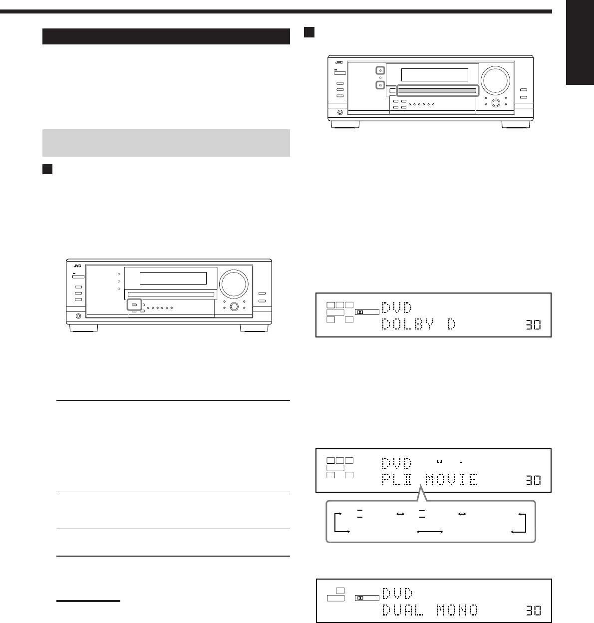
37
English
Activating the Surround Modes
Available Surround modes vary depending on the speaker settings
and the incoming signals. (See page 36.)
Activating one of the Surround modes for a source automatically
recalls the memorized settings and adjustments (see pages 25 to
33.)
You can also use the buttons on the remote control for the same
functions.
Activating the EX/ES setting
For multi-channel digital software, you can activate the EX/ES (7.1-
channel) reproduction mode.
•Once you have set EX/ES (7.1-channel) reproduction mode, it is
stored in memory and will be called up whenever you activate the
Surround mode which the memorized EX/ES (7.1-channel)
reproduction mode can be applied to.
Press EX/ES to select an appropriate setting for your enjoyment.
The currently selected EX/ES (7.1-channel) reproduction mode
appears on the display.
•Each time you press the button, it changes as follows:
EX/ES AUTO*: According to the incoming signal, an
appropriate Surround mode is applied.
•For Dolby Digital EX and DTS-ES,
EX/ES (7.1-channel) reproduction is
applied.
•For 5.1-channel (or less) encoded
software, 5.1-channel reproduction is
applied.
EX/ES ON*: Select to apply EX/ES (7.1-channel)
reproduction to both 5.1-channel and 6.1-
channel encoded software.
EX/ES OFF: Select to cancel the EX/ES (7.1-channel)
reproduction.
*
If the surround back speakers are not connected or deactivated,
Virtual 6.1-channel surround is applied.
Notes:
•When Surround mode is deactivated, pressing EX/ES will
activate an appropriate Surround mode for the current source.
•When an analog or digital 2-channel source is playing, you can
adjust the EX/ES (7.1-channel) reproduction mode and store
the setting, but it will not affect the current source.
•When the source is one to which the EX/ES (7.1-channel)
reproduction cannot be applied, you can adjust the setting and
store in memory, but reproduction channels will remain
unchanged.
Activating the Surround Modes
1. Select and play any source other than “DVD
MULTI.”
•Make sure you have selected the analog or digital input mode.
•Surround modes are not valid for DVD MULTI playback
mode.
2. Press SURROUND to activate the Surround
mode.
•For multi-channel digital software (except 2-channel and
Dual Mono software), incoming signals are automatically
detected and the appropriate surround mode is activated (see
page 36 for details).
–If the EX/ES (7.1-channel) reproduction mode has been set
to “AUTO” or “ON,” one of the EX/ES (7.1-channel)
reproduction modes will be activated (see the left column).
•For analog sources and digital 2-channel software, you can
select one of the following Surround modes. Each time you
press SURROUND, Surround modes change as follows:
•For Dual Mono software, you can select the channel you
listen to. (See page 29.)
To adjust the speaker output level, see pages 32 and 33.
To cancel the Surround mode
Press SURROUND/DSP OFF (or SURR/DSP OFF on the remote
control). “SURR OFF” appears on the display.
Ex. When “DOLBY D” is activated.
VOLUME
LINEAR PCM
DIGITAL
L
SUBWFR
LS RS
CR
LFE
DIGITAL AUTO
SPEAKERS 1
VOLUME
LINEAR PCM
DIGITAL
L
SUBWFR
DUAL DIGITAL AUTO
SPEAKERS 1
VOLUME
LINEAR PCM
L
SUBWFR
R
ANALOG
PRO LOGIC
SPEAKERS 1
NEO:6CINMANEO:6MUSIC
PL
II
MOVIE PL
II
MUSIC PRO LOGIC
34-40_8030&7030[C]7.pm6 03.2.13, 2:52 PM37
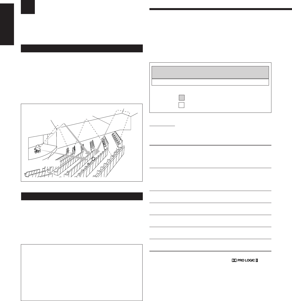
38
English
: Suitable for audio sources
: Suitable for video sources
Using the DSP Modes
This unit activates a variety of DSP modes automatically. The basic settings and adjustments stored (see pages 25 to
33) are applied automatically.
Early reflections
Reflections from
behind
Direct sounds
Reproducing the Sound Field
The sound heard in a concert hall, club, etc. consists of direct sound
and indirect sound—early reflections and reflections from behind.
Direct sounds reach the listener directly without any reflection. On
the other hand, indirect sounds are delayed by the distances of the
ceiling and walls. These direct sounds and indirect sounds are the
most important elements of the acoustic surround effects.
The DSP modes can create these important elements, and give you a
real “being there” feeling.
Introducing the DSP Modes
The DSP modes include the following modes—
•DAP (Digital Acoustic Processor) modes (HALL 1, HALL 2,
LIVE CLUB, DANCE CLUB, PAVILION, THEATER 1,
THEATER 2)
•ALL CH STEREO
•MONO FILM
To use the DSP modes, press DSP so that the DSP modes change as
follows.
The DSP indicator also lights up on the display.
=
HALL 1 =
HALL 2 =
LIVE CLUB
=
DANCE CLUB =
PAVILION =
ALL STEREO
= THEATER 1 =
THEATER 2 =
MONO FILM
=
(Back to the beginning)
DAP modes
You can use the following DAP modes in order to reproduce a more
acoustic sound field in your listening room.
HALL 1: Reproduces the spatial feeling of a large
shoebox-shaped hall designed primarily for
classical concerts. (Its seating capacity is about
2000.)
HALL 2: Reproduces the spatial feeling of a large
vineyard-shaped hall designed primarily for
classical concerts. (Its seating capacity is about
2000.)
LIVE CLUB: Reproduces the spatial feeling of a live music
club with a low ceiling.
DANCE CLUB: Reproduces the spatial feeling of a rocking
dance club.
PAVILION: Reproduces the spatial feeling of an exhibition
hall with a high ceiling.
THEATER 1*:Reproduces the spatial feeling of a large theater
where the seating capacity is about 600.
THEATER 2*:Reproduces the spatial feeling of a small theater
where the seating capacity is about 300.
*
The built-in Dolby Pro Logic II decoder is activated when playing
back 2-channel analog or digital source. The
indicator lights up.
When using the DAP mode, the sounds come out of all the
connected and activated speakers.
•If surround speakers are set to “NONE” in the speaker setting,
JVC’s original 3D-PHONIC processing (which has been
developed to create the surround effect through the front speakers
only) is used.
The 3D-PHONIC indicator lights up on the display.
3D HEADPHONE Mode
You can also enjoy the DSP effect (except All Channel Stereo
mode) through the headphones.
If you press DSP when the front speakers 1 and 2 are both
deactivated, 3D HEADPHONE mode is activated without
respect to the type of software played back.
“3D H PHONE” appears on the display and the DSP and
HEADPHONE indicators also light up.
34-40_8030&7030[C]7.pm6 03.2.13, 2:52 PM38
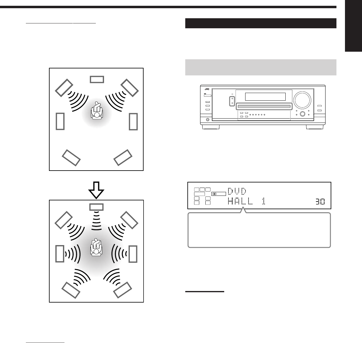
39
English
VOLUME
LINEAR PCM
DIGITAL
L
SUBWFR
LS RS
CR
DIGITAL AUTO
DSP
SPEAKERS 1
ALL Channel Stereo mode
This mode can reproduce a larger stereo sound field using all the
connected (and activated) speakers. This mode cannot be used
without activating the surround speakers.
•If the front speakers are deactivated, “All Channel Stereo”
cannot be selected.
Monaural Film
In order to reproduce a more acoustic sound field in your listening
room while viewing monaural sound video software (analog and 2-
channel digital signals), you can use this mode.
The surround effect will be added, and the sound localization of
actor’s words will be improved. This mode cannot be used for
multi-channel digital signals.
When “MONO FILM” is used, sounds come out of all the
connected (and activated) speakers.
•If incoming signals change from 2-channel digital signal to
another digital signal type, “MONO FILM” is canceled and an
appropriate Surround mode is activated.
Activating the DSP Modes
Activating one of the DSP modes for a source automatically
recalls the memorized settings and adjustments (see pages 25 to
33.)
You can also use the buttons on the remote control for the same
functions.
1. Select and play any sound source.
2. Press DSP repeatedly until the DSP mode you
want appears on the display.
•Each time you press the button, the DSP modes change as
follows:
=
HALL 1 =
HALL 2 =
LIVE CLUB
=
DANCE CLUB =
PAVILION =
ALL STEREO*
= THEATER 1 =
THEATER 2 =
MONO FILM**
=
(Back to the beginning)
*
When surround speakers are set to “NONE,” you cannot
select “ALL STEREO.”
**
When multi-channel signals come in, you cannot select
“MONO FILM.”
Note:
When the surround speakers are deactivated, the 3D-PHONIC
processing is applied to the DSP modes (the 3D-PHONIC indicator
also lights up).
To cancel the DSP modes
Press SURROUND/DSP OFF (or SURR/DSP OFF on the remote
control). “SURR OFF” appears on the display.
•When the front speakers are deactivated, “HEADPHONE” will
appear.
Sound reproduced from normal stereo
Sound reproduced from All Channel Stereo mode
34-40_8030&7030[C]7.pm6 03.2.13, 2:52 PM39
40
English
Using the DVD MULTI Playback Mode
This receiver provides the DVD MULTI playback mode for reproducing the analog discrete output mode of the DVD
player.
Activating the DVD MULTI Playback Mode
1. Press DVD MULTI so that “DVD MULTI”
appears on the display.
The MULTI indicator also lights up.
Note:
When you select “DVD MULTI” as the source to play, the Surround
and DSP modes are canceled, and the SURROUND and DSP
buttons do not work.
2. Select the analog discrete output mode on the
DVD player, and start playing a DVD.
•Refer also to the manual supplied with the DVD player.
You can adjust Digital Equalization patterns and speaker output
levels. See “Adjusting the Equalization Patterns” on page 32 for
details.
Notes:
•Midnight Mode is not available for DVD MULTI playback mode (see
page 20).
•When using a headphones, you can listen to the front channels (left
and right) only.
Connection diagram
DVD
VIDEO
RIGHT LEFT S-VIDEO
VIDEO
AUDIO
SUBWOOFER CENTER
DVD
IN
FRONT
DVD
IN
COMPONENT VIDEO
DVD
IN
SURR
(REAR)
RL
RL
A
B
C
D
E F G
RX-8030VBK/RX-7030VBK
ÅTo component video output
ıTo subwoofer output
ÇTo center channel audio output
ÎTo S-video output
‰To composite video output
ÏTo left/right front channel audio output
ÌTo left/right surround channel audio output
Note:
When connecting a DVD player to the component video input
jacks, make the component video input setting correctly. See
page 30 for details.
VOLUME
LINEAR PCM
L
SUBWFR
LS RS
CR
ANALOG MULTI
SPEAKERS 1
DVD player
34-40_8030&7030[C]7.pm6 03.2.13, 2:52 PM40
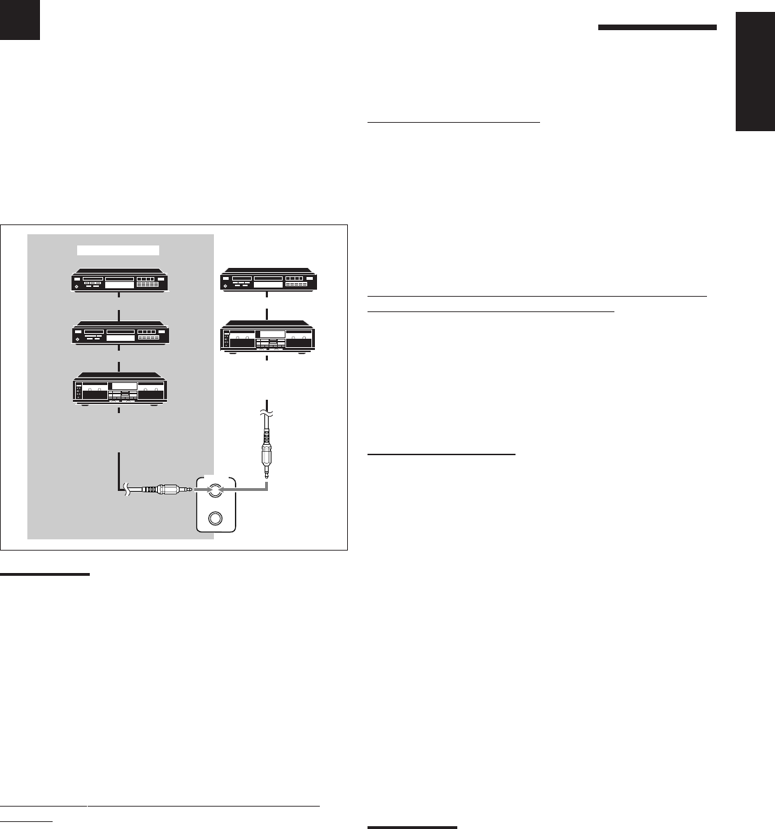
41
COMPU LINK Remote Control System
The COMPU LINK remote control system allows you to operate JVC’s audio components through the remote sensor on
the receiver.
Automatic Source Selection
When you press the play (33
33
3) button on a connected component or
on its own remote control, the receiver automatically turns on and
changes the source to the component. On the other hand, if you
select a new source on the receiver or on the remote control, the
selected component begins playing immediately.
In both cases, the previously selected source continues playing
without sound for a few seconds.
•For RX-7030VBK: You cannot use the COMPU LINK remote
control system to operate the MD recorder.
Automatic Power On/Off (Standby)—only possible with
the COMPU LINK-3 and COMPU LINK-4
The connected components turn on and off (standby) along with the
receiver.
When you turn on the receiver, one of the connected components
will turn on automatically, depending on which component has been
previously selected.
When you turn off the receiver, the connected components will turn
off (standby).
Synchronized Recording
Synchronized recording means the cassette deck (or MD recorder)
starts recording as soon as a CD begins playing.
To use synchronized recording, follow these steps:
1. Put a tape in the cassette deck (or an MD in the
MD recorder), and a disc in the CD player.
2. Press the record (¶) button and the pause (8)
button on the cassette deck (or MD recorder) at
the same time.
This puts the cassette deck (or MD recorder) into recording
pause.
If you do not press the record (¶) button and pause (8) button at
the same time, the synchronized recording feature will not
operate.
3. Press the play (3) button on the CD player.
The source changes on the receiver, and as soon as play starts,
the cassette deck (or MD recorder) starts recording. When the
play ends, the cassette deck (or MD recorder) enters recording
pause, and stops about 4 seconds later.
Notes:
•During synchronized recording, the selected source cannot be
changed.
•If the power of any component is shut off during synchronized
recording, the COMPU LINK remote control system may not
operate properly. In this case, you must start again from the
beginning.
To use this remote control system, you need to connect JVC’s audio
components through the COMPU LINK (SYNCHRO) jacks (see
below) in addition to the connections using cables with RCA pin
plugs (see pages 12 and 13).
•Make sure that the AC power cords of these components are
unplugged before connection. Plug the AC power cords only after
all connections are complete.
Notes:
•There are four versions of COMPU LINK remote control system.
This receiver is equipped with the fourth version—COMPU LINK-4.
This version is added systematic operations with the CD recorder to
the previous version—COMPU LINK-3.
•If your audio component has two COMPU LINK jacks, you can use
either one. If it has only one COMPU LINK jack, connect it so that it
is the last item in the series of components.
•To operate the target component using the COMPU LINK remote
control system, set the source name correctly if required.
(See page 21.)
•Refer also to the manuals supplied with your audio components.
This remote control system allows you to use four functions listed
below.
Remote Control through the Remote Sensor on the
Receiver
You can control the connected audio components through the remote
sensor on the receiver using this remote control. Aim the remote
control directly at the remote sensor on the receiver. For details,
see pages 44 and 45.
COMPU LINK-4
(SYNCHRO)
CD player
CD recorder
Cassette deck
or
MD recorder
Cassette deck
or
CD recorder
CD player
RX-7030VBK
RX-8030VBK
English
41_41_8030&7030[C]7.pm6 03.2.13, 2:52 PM41
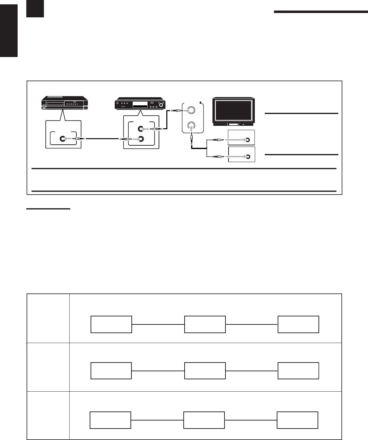
42
English
AV COMPU LINK Remote Control System
The AV COMPU LINK remote control system allows you to operate JVC’s video components (TV, VCR, and DVD player)
through the receiver.
This receiver is equipped with the AV COMPU LINK-III, which adds a function to the previous version in order to operate JVC’s video
components through the video components terminals. To use this remote control system, connect the video components you want to operate,
following the diagrams below and the procedure on the next page.
CONNECTIONS 1: AV COMPU LINK Connection
CAUTION:
You can only connect to the TV
with the AV COMPU LINK EX or
AV COMPU LINK-III jack.
DO NOT connect to the TV with
AV COMPU LINK RECEIVER/
AMP jack.
IMPORTANT:
The AV COMPU LINK remote control system cannot control the DBS tuner.
•For RX-8030VBK: Connect the VCR to the VCR 1 jacks. Video components connected to the VIDEO and VCR 2 jacks on the receiver
cannot be controlled with the AV COMPU LINK remote control system.
Notes:
•When connecting the receiver and a TV with the AV COMPU LINK EX terminal by using a component video cable, you cannot use automatic
selection of TV’s input mode (see page 43).
•When connecting only the VCR or DVD player to this receiver, connect it directly to the receiver using cables with the monaural mini-plugs.
CONNECTIONS 2: Video Cable Connection
This receiver is equipped with three types of the video terminals—S-video, composite video, and component video, and the signals coming
into this receiver through one type of video jacks can output only through the jack of the same type. So you need to connect the VCR and/or
DVD player to the TV using one of the following three ways:
•When using the AV COMPU LINK remote control system, set the component video input for the DVD player and the DBS tuner
correctly (see “Setting the Component Video Input” on page 30); otherwise, the correct input for this receiver will not be selected on the
TV.
CASE 1 When connecting the source equipment to the receiver through the S-video jacks, connect this receiver
to the TV’s Video Input 1 jack using S-video cables.
CASE 2 When connecting the source equipment to the receiver through the composite video jacks, connect
this receiver to the TV’s Video Input 2 jack (composite video input) using composite video cables.
CASE 3 When connecting the source equipment to the receiver through the component video jacks, connect
this receiver to the TV’s Video Input 2 jack (component video input) using component video cables.
Source
equipment
RX-8030VBK
RX-7030VBK TV
To video Input 1
S-video cord
S-video cord
Source
equipment
RX-8030VBK
RX-7030VBK TV
To video Input 2
Composite
video cord
Composite
video cord
Source
equipment
RX-8030VBK
RX-7030VBK TV
To video Input 2
Component
video cord
Component
video cord
AV
COMPULINK-
AV
COMPU LINK
VHS
AV
COMPU LINK AV
COMPU LINK EX
DVD
AV
COMPU LINK-ΙΙΙ
VCR DVD player TV
42-52_8030&7030[C]7.pm6 03.2.13, 2:52 PM42

43
English
1. If you have already plugged your VCR , DVD
player, TV and this receiver into the AC outlets,
unplug their AC power cords first.
2. Connect your VCR, DVD player, TV and this
receiver, using the cables with the monaural mini-
plugs (not supplied).
•See “CONNECTIONS 1” on the previous page.
3. Connect the audio input/output jacks on VCR,
DVD player, TV and this receiver using the cables
with RCA pin plugs.
•See pages 14 and 15.
4. Connect the video input/output jacks on VCR,
DVD player, TV and this receiver, using the
cables with RCA pin plugs, S-video plug or
component video plugs.
•See “CONNECTIONS 2” on the previous page.
5. Plug the AC power cords of the components and
the receiver into the AC outlets.
6. When turning on the TV for the first time after
the AV COMPU LINK connection, turn the TV
volume to the minimum using the TV volume
control on the TV.
7. Turn on the connected components first, then
turn on this receiver.
•When turning on the VCR, use the remote control supplied
with this receiver.
The AV COMPU LINK remote control system allows you to use the
five basic functions listed below.
Remote Control of the TV, DVD player, and VCR Using
This Remote Control
See page 46 for details.
•Aim the remote control directly at the remote sensor on each
target component.
One-Touch Video Play
Simply by inserting a video cassette without its safety tab into the
VCR, you can enjoy the video playback without setting other
switches manually. The receiver automatically turns on and changes
the source to “VCR 1” (for RX-8030VBK) or “VCR” (for RX-
7030VBK).
The TV automatically turns on and changes the input mode to the
appropriate position so that you can view the playback picture.
When you insert a video cassette with its safety tab, press the play
(33
33
3) button on the VCR or on the remote control. So, you can get the
same result.
One-Touch DVD Play
Simply by starting playback on the DVD player, you can enjoy the
DVD playback without setting other switches manually.
•When the DVD player is connected through the analog input jacks
on this receiver (and analog input is selected), the receiver
automatically turns on and changes the source to “DVD” or
“DVD MULTI.”
•When the DVD player is connected through the digital input
terminal on this receiver (and digital input is selected), the
receiver automatically turns on and changes the source to “DVD.”
The TV automatically turns on and changes the input mode to the
appropriate position so that you can view the playback picture.
Automatic Selection of TV’s Input Mode
•When you select “TV” as the source to play on the receiver, the
TV automatically changes the input mode to the TV tuner so that
you can watch TV.
•When you select any other video source other than “TV” as the
source to play on the receiver, the TV automatically changes the
input mode to the appropriate position (either Video Input 1 or
Video Input 2) so that you can view the playback picture.
Notes:
•When you select “TV” as the source on the receiver, you cannot see
the menu on the TV screen since the AV COMPU LINK remote
control system automatically changes the TV’s input mode to the
TV tuner.
•This function does not work when you connect this receiver and the
TV with the AV COMPU LINK EX terminal using a component video
cable. In this case, reconnect the TV referring to case 1 or case 2 on
page 42.
Automatic Power On/Off
The TV, VCR, and DVD player turn on and off along with the
receiver.
When you turn on the receiver;
•If the previously selected source is “VCR 1” (for RX-8030VBK)
or “VCR” (for RX-7030VBK), the TV and VCR will turn on
automatically.
•If the previously selected source is “DVD” or “DVD MULTI,” the
TV and DVD player will turn on automatically.
•If the previously selected source is any video source other than the
above, only the TV will turn on automatically.
When you turn off the receiver, the TV, VCR and the DVD player
will turn off.
Note:
If you turn off the receiver while recording on the VCR, the VCR will
not turn off, but continue recording.
42-52_8030&7030[C]7.pm6 03.2.13, 2:52 PM43
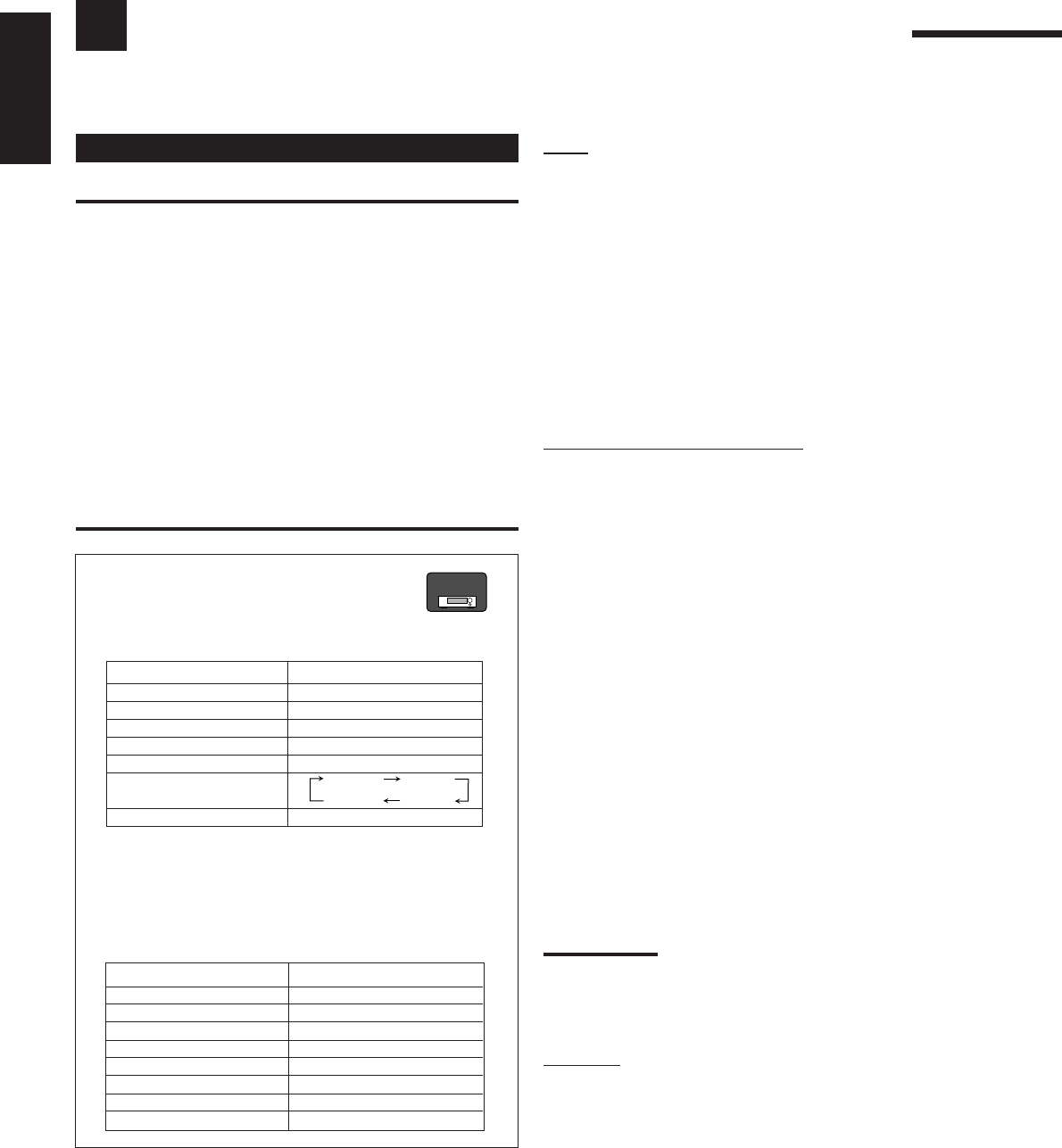
44
English
Operating JVC’s Audio/Video Components
You can operate JVC’s audio and video components with this receiver’s remote control, since control signals for JVC’s
components are preset in the remote control.
Tuner
You can always perform the following operations:
FM/AM: Alternate between FM and AM.
After pressing FM/AM, you can perform the following operations
on a tuner:
1 – 10/0, +10: Select a preset channel number directly.
For channel number 5, press 5.
For channel number 15, press +10, then 5.
For channel number 20, press +10, then 10/0.
TUNING UP/DOWN:
Tune into stations.
FM MODE: Change the FM reception mode.
Sound control section (Amplifier)
You can always perform the following operations:
SURROUND: Turn on and select Surround modes
DSP: Turn on and select DSP modes.
SURR/DSP OFF: Turn off Surround and DSP modes.
After pressing SOUND, you can perform the following operations:
FRONT•L then LEVEL +/–:Adjust the left front speaker output
level.
FRONT•R then LEVEL +/–:Adjust the right front speaker output
level.
CENTER then LEVEL +/–: Adjust the center speaker output level.
SURR•L then LEVEL +/–: Adjust the left surround speaker
output level.
SURR•R then LEVEL +/–: Adjust the right surround speaker
output level.
SURR BACK: Adjust the surround back speaker
output level.
SUBWOOFER then LEVEL +/–:
Adjust the subwoofer output level.
DIGITAL EQ then LEVEL+/–: Select the sound frequency bands
and adjust its level.
TEST: Turn on or off test tone output.
BASS BOOST: Turn on or off Bass Boost.
Note:
After adjusting sounds, press the corresponding source selection
button to operate your target source by using the 10 keys; otherwise,
the 10 keys cannot be used for operating your target source.
CD player
After pressing CD, you can perform the following operations on a
CD player:
3:Start playing.
4:Return to the beginning of the current (or previous)
track.
¢: Skip to the beginning of the next track.
7:Stop playing.
8:Pause playing. To resume, press 3.
1 – 10/0, +10:
Select a track number directly.
For track number 5, press 5.
For track number 15, press +10, then 5.
For track number 20, press +10, then 10/0.
For track number 30, press +10, +10, then 10/0.
Operating Audio Components
IMPORTANT:
To operate JVC’s audio components using the supplied remote
control:
•You need to connect JVC’s audio components through the
COMPU LINK (SYNCHRO) jacks (see page 41) in addition to
the connections using cables with RCA pin plugs (see pages 11 to
13).
•Aim the remote control directly at the remote sensor on the
receiver.
•If you use the buttons on the front panel to choose a source, the
remote control will not operate that source. To operate a source
with the remote control, the source must be selected using source
selection buttons on the remote control.
•To operate the target component using the COMPU LINK remote
control system, set the source name correctly if required. (See
page 21.)
•Refer also to the manuals supplied with your components.
For RX-8030VBK:
•When you press one of the source selection
buttons, the remote operation mode appears on
the display window for about two hours.
Buttons Indications
FM/AM TUNER
CD CD
CDR CDR
PHONO PHONO
TAPE/MD TAPE
CONTROL (repeatedly)*
SOUND SOUND
*
By pressing CONTROL repeatedly, you can select “VCR 1,”
“TAPE,” “CDR” or “CDDSC” as the source.
•When you press one of the following buttons, the remote
operation mode appears on the display window for about two
hours.
Buttons Indications
FRONT•L FRL
FRONT•R FRR
CENTER CTR
SURR•L SURRL
SURR•R SURRR
SURR BACK SBK
SUBWOOFER S-WFR
DIGITAL EQ EQ
RX-8030V
ONLY
VCR 1 TAPE
CDR
CDDSC
42-52_8030&7030[C]7.pm6 03.2.13, 2:52 PM44

45
English
CD changer
For RX-8030VBK:
After selecting “CDDSC” by pressing CONTROL repeatedly, you
can perform the following operations on a CD changer:
For RX-7030VBK:
After pressing CD DISC, you can perform the following operations
on a CD changer:
3:Start playing.
4:Return to the beginning of the current (or previous)
track.
¢:Skip to the beginning of the next track.
7:Stop playing or recording.
8:Pause playing. To resume, press 3.
1 – 6, 7/P: Select the number of a disc installed in a CD
changer.
After pressing CD, you can perform the following operations on a
CD changer:
1 – 10/0, +10: Select a track number directly.
For track number 5, press 5.
For track number 15, press +10, then 5.
For track number 20, press +10, then 10/0.
For track number 30, press +10, +10, then 10/0.
Example:
•Selecting disc number 4, track number 12, and starting playback.
For RX-8030VBK:
1. Press CONTROL repeatedly until “CDDSC” appears on the
display window, then press 4.
2. Press CD, then press +10, 2.
For RX-7030VBK:
1. Press CD DISC, then press 4.
2. Press CD, then press +10, 2.
If your CD changer is of 200-disc loading capability (except for
XL-MC100 and XL-MC301),
you can do the following operations using the 10 keys after pressing
CD.
1. Select a disc number.
2. Then select a track number (always enter two digits).
3. Start playback.
Examples:
•Selecting disc number 3, track number 2, and starting playback.
Press 3, then, 0, 2, then 3.
•Selecting disc number 10, track number 5, and starting playback.
Press 1, 0, then, 0, 5, then 3.
•Selecting disc number 105, track number 12, and starting
playback. Press 1, 0, 5, then 1, 2, then 3.
Turntable
After pressing PHONO, you can perform the
following operations on a turntable:
3:Start playing.
7:Stop playing.
CD recorder
For RX-8030VBK: After pressing CDR (or selecting “CDR” by
pressing CONTROL repeatedly), you can perform the following
operations on a CD recorder:
For RX-7030VBK: After pressing TAPE/CDR (or TAPE/CDR
CONTROL), you can perform the following operations on a CD
recorder:
3:Start playing.
4:Return to the beginning of the current (or previous)
track.
¢:Skip to the beginning of the next track.
7:Stop playing or recording.
8:Pause playing. To resume, press 3.
1 – 10/0, +10: Select a track number directly.
For track number 5, press 5.
For track number 15, press +10, then 5.
For track number 20, press +10, then 10/0.
For track number 30, press +10, +10, then 10/0.
REC PAUSE: Enter recording pause by pressing this button.
To start recording again, press this button then 3.
Cassette deck
For RX-8030VBK: After pressing TAPE/MD (or selecting “TAPE”
by pressing CONTROL repeatedly), you can perform the following
operations on a cassette deck:
For RX-7030VBK: After pressing TAPE/CDR (or TAPE/CDR
CONTROL), you can perform the following operations on a cassette
deck:
3:Start playing.
REW: Fast wind the tape from right to left.
FF: Fast wind the tape from left to right.
7:Stop playing or recording.
8:Pause playing. To resume, press 3.
REC PAUSE:
Enter recording pause by pressing this button.
To start recording again, press this button then 3.
MD recorder
After pressing TAPE/MD (or selecting “TAPE*” by
pressing CONTROL repeatedly), you can perform the
following operations on a MD recorder:
3:Start playing.
4:Return to the beginning of the current (or previous)
track.
¢:Skip to the beginning of the next track.
7:Stop playing or recording.
8:Pause playing. To resume, press 3.
REC PAUSE: Enter recording pause by pressing this button.
To start recording again, press this button then 3.
*
Selecting “TAPE” will allow you to control the MD recorder.
RX-8030V
ONLY
Note:
You can use either source selection buttons or the control button (CONTROL for RX-8030VBK or TAPE/CDR CONTROL for RX-7030VBK)
to activate the buttons for the target source. If you press one of the source selection buttons, the playing source also changes. On the other
hand, pressing the control button does not change the playing source.
RX-8030V
ONLY
42-52_8030&7030[C]7.pm6 03.2.13, 2:52 PM45
46
English
VCR
You can always perform the following operations:
VCR 1 (for RX-8030VBK) or VCR (for RX-7030VBK):
Turn on or off a VCR.
For RX-8030VBK: After pressing VCR 1 (or selecting “ VCR 1”
by pressing CONTROL repeatedly), you can perform the following
operations on a VCR:
For RX-7030VBK: After pressing VCR (or VCR CONTROL), you
can perform the following operations on a VCR:
1 – 9, 0: Select the TV channels on a VCR.
3:Start playing.
REW: Rewind a tape.
FF: Fast wind a tape.
7:Stop playing or recording.
8:Pause playing. To resume, press 3.
REC PAUSE: Enter recording pause by pressing this button.
To start recording again, press this button then 3.
CH +/–:Change the TV channels on the VCR.
Note:
You can use either VCR 1 (for RX-8030VBK) or VCR (for RX-
7030VBK) or the control button (CONTROL for RX-8030VBK or VCR
CONTROL for RX-7030VBK) to activate the buttons listed above. If
you press one of the source selection buttons, the playing source also
changes. On the other hand, pressing the control button does not
change the playing source.
DVD player
After pressing DVD or DVD MULTI, you can perform the
following operations on a DVD player:
3:Start playing.
4:Return to the beginning of the current (or previous) chapter.
¢:Skip to the beginning of the next chapter.
7:Stop playing.
8:Pause playing. To resume, press 3.
After pressing DVD or DVD MULTI,
these buttons can be used for the DVD
menu operations.
Note:
For detailed menu operations, refer to the
instructions supplied with the discs or the
DVD player.
TV
You can always perform the following operations:
TV : Turn on or off the TV.
TV VOL +/–: Adjust the volume.
TV/VIDEO: Set the input mode (either TV or VIDEO).
After pressing TV/DBS, you can perform the following operations
on a TV:
CH +/–:Change the channels.
1 – 9, 0, 100+: Select the channels.
RETURN: Alternate between the previously selected channel
and the current channel.
Operating Video Components
IMPORTANT:
To operate JVC’s video components using the supplied remote
control:
•You need to connect JVC’s video components through the AV
COMPU LINK jacks (see page 42) in addition to the connections
using cables with RCA pin plugs (see pages 14 and 15).
•Some JVC’s VCRs can accept two types of the control signals—
remote code “A” and “B.” Before using this remote control, make
sure that the remote control code of the target VCR is set to code
“A.”
–For RX-8030VBK: When another JVC’s VCR is connected to
the VCR 2 or VIDEO terminals, set its remote control code to
code “B.” (This remote control cannot emit the control signals of
code “B.”)
•When using the remote control, aim the remote control directly at
the remote sensor on each component, not on the receiver.
For RX-8030VBK:
•When you press one of the source selection
buttons, the operation mode appears on the
display window.
Buttons Indications
VCR 1 VCR 1
DVD or DVD MULTI DVD
TV/DBS TV
CONTROL (repeatedly)*
*
By pressing CONTROL repeatedly, you can select
“VCR 1,” “TAPE,” “CDR” or “CDDSC” as the source.
23
456
8
MENU
ENTER
VCR 1 TAPE
CDR
CDDSC
When you press one of the buttons listed above, the remote
operation mode appears on the operation mode display for
about two hours.
RX-8030V
ONLY
42-52_8030&7030[C]7.pm6 03.2.13, 2:52 PM46

47
English
Operating Other Manufacturers’ Video Equipment
This remote control supplied with the receiver can transmit control signals for other manufacturers’ TVs, CATV
converters, DBS tuners, VCRs and DVD players.
When operating the other manufacturers’ components, refer also to
the manuals supplied with them.
•After replacing batteries for the remote control, you need to set
the manufactures’ codes again.
To change the transmittable signals for
operating another manufacturer’s TV
1. Press and hold TV .
2. Press TV/DBS.
For RX-8030VBK: “CALL” appears on the display window of
the remote control.
3. Enter a manufacturer’s code using buttons 1 – 9,
and 0.
See the list on page 49 to find the code.
4. Release TV .
The following buttons can be used for operating a TV:
TV :Turn on and off a TV.
TV VOL +/–:Adjust the volume.
TV/VIDEO: Set the input mode (either TV or VIDEO).
After pressing TV/DBS, you can perform the following
operations on a TV:
CH +/–:Change the channels.
1 – 10/0, 0, 100+ (+10):
Select the channels.
The 10/0 button will function as the ENTER
button if your TV requires pressing ENTER
after selecting a channel number.
Notes:
•All the functions listed above may not be assigned to the
buttons for some TVs.
•If you cannot change the channels of some TVs by pressing
10 keys, press CH +/– for changing the channels.
5. Try to operate your TV by pressing TV .
When your TV turns on or off, you have entered the correct
code.
If there are more than one code listed for your brand of TV,
try each one until the correct one is entered.
To change the transmittable signals for
operating a CATV converter or DBS tuner
1. Press and hold CATV/DBS .
2. Press CATV/DBS CONTROL.
For RX-8030VBK: “CALL” appears on the display window of
the remote control.
3 Enter a manufacturer’s code using buttons 1 – 9,
and 0.
See the list on page 49 to find the code.
4. Release CATV/DBS .
The following buttons can be used for operating a CATV
converter and DBS tuner:
CATV/DBS :Turn on and off a CATV converter or DBS
tuner.
After pressing CATV/DBS CONTROL, you can perform the
following operations on a CATV converter or DBS tuner:
CH +/–:Change the channels.
1 – 10/0, 0, 100+ (+10):
Select the channels.
The 10/0 button will function as the ENTER
button if your equipment requires pressing
ENTER after selecting a channel number.
5. Try to operate your CATV converter or DBS
tuner by pressing CATV/DBS .
When your CATV converter or DBS tuner turns on or off, you
have entered the correct code.
If there are more than one code listed for your brand of
CATV converter or DBS tuner, try each one until the correct
one is entered.
Note:
You cannot preset the signals for both the CATV converter and DBS
tuner at the same time.
42-52_8030&7030[C]7.pm6 03.2.13, 2:52 PM47
48
English
To change the transmittable signals for
operating another manufacturer’s DVD player
1. Press and hold AUDIO .
2 Press DVD.
For RX-8030VBK: “CALL” appears on the display window of
the remote control.
3. Enter a manufacturer’s code using buttons 1 – 9,
and 0.
See the list on page 49 to find the code.
4. Release AUDIO .
After pressing DVD or DVD MULTI, you can perform the
following operations on a DVD player:
3: Start playing.
4: Return to the beginning of the current (or previous)
chapter.
¢: Skip to the beginning of the next chapter.
7: Stop playing.
8: Pause playing. To resume, press 3.
After pressing DVD or DVD MULTI,
these buttons can be used for the DVD
menu operations.
Note:
For detailed menu operations, refer to the
instructions supplied with the discs or the
DVD player.
5. Try to operate your DVD player by pressing one
of the above buttons.
•DO NOT forget to turn on a DVD player before pressing one
of the above buttons.
If there are more than one code listed for your brand of
DVD, try each one until the correct one is entered.
23
456
8
MENU
ENTER
To change the transmittable signals for
operating another manufacturer’s VCR
1. Press and hold VCR 1 (for RX-8030VBK) or
VCR (for RX-7030VBK).
2. Press VCR 1 (for RX-8030VBK) or VCR (for RX-
7030VBK).
For RX-8030VBK: “CALL” appears on the display window of
the remote control.
3. Enter manufacturer’s code using buttons 1 – 9,
and 0.
See the list on page 49 to find the code.
4. Release VCR 1 or VCR .
The following buttons can be used for operating a VCR:
VCR 1 :For RX-8030VBK—Turn on and off a VCR.
VCR : For RX-7030VBK—Turn on and off a VCR.
After pressing VCR 1 or VCR, you can perform the following
operations on a VCR:
CH +/–:Change the TV channels on a VCR.
1 – 10/0, 0, 100+ (+10):
Select the TV channels.
The 10/0 button will function as the ENTER
button if your VCR requires pressing ENTER
after selecting a channel number.
3:Start playback.
REW: Rewind a tape.
FF: Fast wind a tape.
7:Stop playing or recording.
8:Pause playing. To resume, press 3.
REC PAUSE: Enter recording pause by pressing this button.
To start recording again, press this button
then 3.
5. Try to operate your VCR by pressing VCR 1
or VCR .
When your VCR turns on or off, you have entered the correct
code.
If there are more than one code listed for your brand of
VCR, try each one until the correct one is entered.
42-52_8030&7030[C]7.pm6 03.2.13, 2:52 PM48
49
English
Manufacturer Codes
JVC 00*, 02
Denon 01
Panasonic 03
Philips 13
Pioneer 04, 05, 06
RCA 07
Samsung 08
Sony 09
Toshiba 10
Yamaha 11, 12
Manufacturers’ codes are subject to change without notice. If they
are changed, this remote control cannot operate the equipment.
Manufacturer Codes
JVC 00*, 26, 27, 28, 29, 58
Aiwa 01, 02
Bell & Howell 03
Blaupunkt 04, 05
CGM 06, 07
Emerson 08, 10, 11, 12, 64, 65
Fisher 03, 14, 15, 16, 17
Funai 01
GE 18, 19, 20
Goldstar 07
Goodmans 13, 21
Grundig 06, 22
Hitachi 18, 23, 24, 25, 66
Loewe 07, 21
Magnavox 04, 19, 24
Mitsubishi 30, 31, 32, 33, 34, 35
NEC 26, 27
Nokia 03, 36
Nordmende 38
Orion 09
Panasonic 19, 24, 39, 40
Philips 04, 19, 21, 24, 41, 42
Phonola 21
RCA/Proscan 04, 18, 19, 23, 24, 43, 44, 45
SABA 38, 46
Samsung 45, 47, 59, 61, 62, 63
Sanyo 03, 48, 49
Sharp 37, 50
Siemens 03, 51
Sony 52, 53, 54
Telefunken 55, 60
Toshiba 43, 44
Zenith 56, 57
For CATV converter
Manufacturer Codes
General Instrument 06, 07, 08, 09, 10, 11,
12, 13, 14, 29
Hamlin/Regal 01, 02, 03, 04, 05
Jerrold 06, 07, 08, 09, 10, 11,
12, 13, 14
Oak 15, 16, 17
Panasonic 18, 19, 20
Pioneer 21, 22
Scientific Atlanta 23, 24, 25
Tocom 26
Zenith 27, 28
Manufacturer Codes
JVC 56*, 57, 67
Amstrad 43, 44, 45, 46, 47, 48, 49
Blaupunkt 30
Echostar 50, 51, 67
Goldstar 31
Grundig 32, 33
Hirshmann 48, 52, 53, 54, 55
Instrument 68
ITT/NOKIA 34
Kathrein 52, 58, 59, 60, 61, 62, 63
NEC 35, 36
Orbitech 48
Philips 37, 38
RCA 65
Samsung 39, 40
Schwaiger 61, 64
Siemens 41, 42
Sony 66
Technisat 48
For DBS tuner
*Initial setting
Manufacturer Codes
JVC 00*, 02, 13,
14, 47, 74
Akai 01, 02
Blaupunkt 03, 04
Fisher 01, 05
Grundig 03, 06, 07
Hitachi 08, 09, 10, 49
Irradio 02
ITT/NOKIA 11, 12
Loewe 06, 15, 16
Magnavox 08, 17, 49
Mets 50, 51, 52, 53
Mitsubishi 08, 18, 19, 20
Mivar 21
Nordmende 22, 23
Okano 15
Panasonic 24, 25, 26, 27
76
Philips 15, 17, 28, 75
Manufacturer Codes
Quelle 52, 53, 54, 55,
56, 57, 58, 59,
60, 61, 62, 63,
64, 65, 66, 67
RCA/ 08, 24, 29, 30,
Proscan 31, 48
SABA 32, 33, 68, 69,
70
Samsung 06, 08, 16, 34,
35, 49
Sanyo 01, 05
Schneider 02, 15, 36
Sharp 37, 38, 77
Sony 39
Telefunken 40, 41, 42, 69
Thomson 71, 72
Toshiba 37, 43, 44
Zenith 45, 46
For TV For VCR
For DVD player
42-52_8030&7030[C]7.pm6 03.2.13, 2:52 PM49
50
English
Troubleshooting
Use this chart to help you solve daily operational problems. If there is any problem you cannot solve, contact your JVC’s
service center.
SOLUTION
Plug the power cord into an AC outlet.
Check speaker wiring and reconnect if necessary. (See
pages 9 to 11.)
Press SPEAKERS ON/OFF 1 and SPEAKERS ON/
OFF 2 correctly. (See page 19.)
Select the correct source.
Press MUTING to cancel the mute. (See page 22.)
Select the correct input mode (analog or digital). (See
page 19.)
Check speaker wiring and reconnect if necessary. (See
pages 9 to 11.)
Connect an outdoor FM antenna or contact your
dealer. (See page 8.)
Select a new station.
Check with your dealer to be sure you have the correct
antenna.
Check connections. (See page 8.)
Move the antenna farther from automobile traffic.
Connect the cable to the screw marked (H) on the
rear.
Move the speakers away from the turntable.
Turn off Analog Direct. (See page 21.)
Select the source other than DVD MULTI. (See page
40.)
Play back software bearing the mark or
.
Set “EX/ES” setting to “ON.” (See page 37.)
1. Press STANDBY/ON on the front panel to
turn off the receiver.
2. Stop the playback source.
3. Turn on the receiver again, and adjust the volume.
Press STANDBY/ON on the front panel to turn off
the receiver, then check the speaker wiring.
If “OVERLOAD” does not disappear, unplug the AC
power cord, then plug it back again.
If speaker wiring is not short-circuited, contact your
dealer.
Press STANDBY/ON on the front panel to turn off
the receiver. After unplugging the AC power cord,
consult your dealer.
Remove the obstruction.
Replace batteries. (See page 8.)
Select the correct remote control operation mode. (See
pages 44 to 49.)
POSSIBLE CAUSE
The power cord is not plugged in.
Speaker signal cables are not connected.
The SPEAKERS ON/OFF 1 and
SPEAKERS ON/OFF 2 buttons are not
set correctly.
An incorrect source is selected.
Muting is activated.
An incorrect input mode (analog or
digital) is selected.
Speaker signal cables are not connected
properly.
Incoming signal is too weak.
The station is too far away.
An incorrect antenna is used.
Antennas are not connected properly.
Ignition noise from automobiles.
A ground cable from the turntable is not
connected to the screw marked (H) on
the rear.
Your turntable is too close to the
speakers.
Analog Direct is turned on.
DVD MULTI is selected as the source.
Software or setting is not for Dolby
Digital EX or DTS ES software.
Speakers are overloaded because of high
volume.
Speakers are overloaded because of
short circuit of speaker terminals.
The receiver is overloaded because of a
high voltage.
There is an obstruction between the
remote sensor on the receiver and the
remote control.
Batteries are weak.
An incorrect remote control operation
mode is selected.
PROBLEM
The display does not light up.
No sound from speakers.
Sound from one speaker only.
Continuous hiss or buzzing during FM
reception.
Noise is heard during FM/AM reception.
Howling during record playing.
No sound effect such as Surround mode,
DSP mode and Digital Equalization.
EX/ES (7.1-channel) reproduction cannot
be done for Dolby Digital EX or DTS ES
software.
“OVERLOAD” starts flashing on the
display.
The STANDBY lamp lights up after
turning on the power, and soon the
receiver turns off again (into standby
mode).
Remote control does not work.
Remote control does not work as you
intend.
42-52_8030&7030[C]7.pm6 03.2.13, 2:52 PM50

51
English
Specifications
RX-8030VBK
Amplifier
Output Power
At Stereo operation
Front ch: 130 W per channel, min. RMS, driven into 8 Ω,
20 Hz to 20 kHz, with no more than 0.08%
total harmonic distortion.
At Surround operation:
Front ch: 130 W per channel, min. RMS, driven into 8 Ω at
1 kHz, with no more than 0.8% total harmonic
distortion.
Center ch: 130 W, min. RMS, driven into 8 Ω at 1 kHz, with
no more than 0.8% total harmonic distortion.
Surround ch: 130 W per channel, min. RMS, driven into 8 Ω at
1 kHz, with no more than 0.8% total harmonic
distortion.
Surround Back ch:
130 W, min. RMS, driven into 8 Ω at 1 kHz, with
no more than 0.8% total harmonic distortion.
Audio
Audio Input Sensitivity/Impedance (1 kHz)
PHONO IN (MM): 2.5 mV/47 kΩ
DVD IN, VCR 1 IN, VCR 2 IN, TV SOUND/DBS IN, VIDEO IN:
200 mV/47 kΩ
CD IN, CDR IN, TAPE/MD IN: 200 mV/47 kΩ
Audio Input (DIGITAL IN)*
Coaxial: DIGITAL 1 (DVD): 0.5 V(p-p)/75 Ω
Optical:
DIGITAL 2 (CD), DIGITAL 3 (TV), DIGITAL 4 (CDR):
–21 dBm to –15 dBm (660 nm ±30 nm)
* Corresponding to Linear PCM, Dolby Digital, and DTS Digital
Surround (with sampling frequency — 32 kHz, 44.1 kHz, 48 kHz).
Audio Output Level: PRE OUT: 1 V
Recording Output Level: VCR 1 OUT, VCR 2 OUT, CDR OUT,
TAPE/MD OUT: 200 mV
Digital output: Optical: DIGITAL OUTPUT
Signal wave length: 660 nm
Output level: –21 dBm to –15 dBm
Signal-to-Noise Ratio (’66 IHF/’78 IHF)
PHONO IN: 70 dB/78 dB (at REC OUT)
DVD IN, VCR 1 IN, VCR 2 IN, TV SOUND/DBS IN, VIDEO:
87 dB/80 dB
CD IN, CDR IN, TAPE/MD IN: 87 dB/80 dB
Frequency Response (8 Ω)
PHONO IN: 20 Hz to 20 kHz (±1 dB)
DVD IN, VCR 1 IN, VCR 2 IN, TV SOUND/DBS IN, VIDEO:
20 Hz to 100 kHz (+1 dB, –3 dB)
CD IN, CDR IN, TAPE/MD IN: 20 Hz to 100 kHz (+1 dB, –3 dB)
RIAA Phono Equalization: ±1.0 dB (20 Hz to 20 kHz)
Equalization (5 bands):
63 Hz, 250 Hz, 1 kHz, 4 kHz, 16 kHz (±8 dB)
Bass boost: +6 dB ±1.0 dB at 100 Hz
Video
Video Input Sensitivity/Impedance
Composite video:
DVD IN, VCR 1 IN, VCR 2 IN, TV SOUND/DBS IN, VIDEO:
1 V(p-p)/75 Ω
S-video:
DVD IN, VCR 1 IN, VCR 2 IN, TV SOUND/DBS IN, VIDEO:
(Y: luminance): 1 V(p-p)/75 Ω
(C: chrominance, burst): 0.286 V(p-p)/75 Ω
Component video: DVD IN, DBS IN:
(Y: luminance): 1 V(p-p)/75 Ω
(PB/PR): 0.7 V(p-p)/75 Ω
Video Output Level
Composite video:
VCR 1 OUT, VCR 2 OUT, MONITOR OUT 1 V(p-p)/75 Ω
S-video: VCR 1 OUT, VCR 2 OUT, MONITOR OUT
(Y: luminance): 1 V(p-p)/75 Ω
(C: chrominance, burst): 0.286 V(p-p)/75 Ω
Component video: MONITOR OUT:
(Y: luminance): 1 V(p-p)/75 Ω
(PB/PR): 0.7 V(p-p)/75 Ω
Synchronization: Negative
Signal-to-Noise Ratio: 45 dB
FM tuner (IHF)
Tuning Range: 87.5 MHz to 108.0 MHz
Usable Sensitivity: Monaural: 12.8 dBf (1.2 µV/75 Ω)
50 dB Quieting Sensitivity: Monaural: 16.0 dBf (1.7 µV/75 Ω)
Stereo: 37.5 dBf (20.5 µV/75 Ω)
Stereo Separation at REC OUT: 35 dB at 1 kHz
AM tuner
Tuning Range: 530 kHz to 1 710 kHz
General
Power Requirements: AC 120V , 60 Hz
Power Consumption: 320 W/440 VA (at operation)
2 W (in standby mode)
Dimensions (W x H x D): 435 mm x 157 mm x 425 mm
(17 3/16 in. x 6 3/16 in. x 16 3/4 in.)
Mass: 12.2 kg (27.0 lbs)
Designs & specifications are subject to change without notice
42-52_8030&7030[C]7.pm6 03.2.13, 2:52 PM51

52
English
.
RX-7030VBK
Amplifier
Output Power
At Stereo operation
Front ch: 110 W per channel, min. RMS, driven into 8 Ω,
20 Hz to 20 kHz, with no more than 0.08%
total harmonic distortion.
At Surround operation:
Front ch: 110 W per channel, min. RMS, driven into 8 Ω at
1 kHz, with no more than 0.8% total harmonic
distortion.
Center ch: 110 W, min. RMS, driven into 8 Ω at 1 kHz, with
no more than 0.8% total harmonic distortion.
Surround ch: 110 W per channel, min. RMS, driven into 8 Ω at
1 kHz, with no more than 0.8% total harmonic
distortion.
Surround Back ch:
110 W, min. RMS, driven into 8 Ω at 1 kHz, with
no more than 0.8% total harmonic distortion.
Audio
Audio Input Sensitivity/Impedance (1 kHz)
DVD IN, VCR IN, TV SOUND/DBS IN: 200 mV/47 kΩ
CD IN, TAPE/CDR IN: 200 mV/47 kΩ
Audio Input (DIGITAL IN)*
Coaxial:DIGITAL 1 (DVD): 0.5 V(p-p)/75 Ω
Optical:
DIGITAL 2 (CD), DIGITAL 3 (TV), DIGITAL 4 (CDR):
–21 dBm to –15 dBm (660 nm ±30 nm)
* Corresponding to Linear PCM, Dolby Digital, and DTS Digital
Surround (with sampling frequency — 32 kHz, 44.1 kHz, 48 kHz).
Audio Output Level: SUBWOOFER OUT: 1 V
Recording Output Level: VCR OUT, TAPE/CDR OUT: 200 mV
Digital output: Optical: DIGITAL OUT
Signal wave length: 660 nm
Output level: –21 dBm to –15 dBm
Signal-to-Noise Ratio (’66 IHF/’78 IHF)
DVD IN, VCR IN, TV SOUND/DBS IN: 87 dB/80 dB
CD IN, TAPE/CDR IN: 87 dB/80 dB
Frequency Response (8 Ω)
DVD IN, VCR IN, TV SOUND/DBS IN:
20 Hz to 100 kHz (+1 dB, –3 dB)
CD IN, TAPE/CDR IN: 20 Hz to 100 kHz (+1 dB, –3 dB)
Equalization (5 bands):
63 Hz, 250 Hz, 1 kHz, 4 kHz, 16 kHz (±8 dB)
Bass boost: +6 dB ±1.0 dB at 100 Hz
Video
Video Input Sensitivity/Impedance
Composite video: DVD IN, VCR IN, TV SOUND/DBS IN:
1 V(p-p)/75 Ω
S-video: DVD IN, VCR IN, TV SOUND/DBS IN:
(Y: luminance): 1 V(p-p)/75 Ω
(C: chrominance, burst): 0.286 V(p-p)/75 Ω
Component video: DVD IN, DBS IN:
(Y: luminance): 1 V(p-p)/75 Ω
(PB/PR): 0.7 V(p-p)/75 Ω
Video Output Level
Composite video: VCR OUT, MONITOR OUT 1 V(p-p)/75 Ω
S-video: VCR OUT, MONITOR OUT
(Y: luminance): 1 V(p-p)/75 Ω
(C: chrominance, burst): 0.286 V(p-p)/75 Ω
Component video: MONITOR OUT
(Y: luminance): 1 V(p-p)/75 Ω
(PB/PR): 0.7 V(p-p)/75 Ω
Synchronization: Negative
Signal-to-Noise Ratio: 45 dB
FM tuner (IHF)
Tuning Range: 87.5 MHz to 108.0 MHz
Usable Sensitivity: Monaural: 12.8 dBf (1.2 µV/75 Ω)
50 dB Quieting Sensitivity: Monaural: 16.0 dBf (1.7 µV/75 Ω)
Stereo: 37.5 dBf (20.5 µV/75 Ω)
Stereo Separation at REC OUT: 35 dB at 1 kHz
AM tuner
Tuning Range: 530 kHz to 1 710 kHz
General
Power Requirements: AC 120V , 60 Hz
Power Consumption: 320 W/440 VA (at operation)
2 W (in standby mode)
Dimensions (W x H x D): 435 mm x 157 mm x 425 mm
(17 3/16 in. x 6 3/16 in. x 16 3/4 in.)
Mass: 12.1 kg (26.7 lbs)
Designs & specifications are subject to change without notice
42-52_8030&7030[C]7.pm6 03.2.13, 2:52 PM52

1
Français
Table des matières
Réglages de base....................................... 25
Configuration des enceintes ..................................................... 25
Éléments des réglages de base ................................................. 26
Procédure de base ..................................................................... 27
Réglage des enceintes ........................................................ 27
Réglage de la distance des enceintes ................................. 28
Réglage des sons graves .................................................... 28
Sélection du canal principal ou du sous-canal
—DUAL MONO ............................................................... 29
Réglage des prises d’entrée numériques ............................ 29
Réglage de l’entrée en composantes vidéo ........................ 30
Mémorisation du niveau de volume pour chaque source .... 30
Ajustment du son ...................................... 31
Éléments des réglages de base ................................................. 31
Procédure de base ..................................................................... 31
Ajustement des courbes d’égalisation................................ 32
Ajustement des niveaux de sortie des enceintes ................ 32
Ajustement des paramètres du son pour les
modes Surround et DSP ............................................... 33
Utilisation des modes Surround .................. 34
Reproduction de l’ambiance d’un cinéma................................ 34
Introduction des modes Surround ............................................ 34
Modes Surround applicables à divers supports ........................ 36
Mise en service du mode Surround .......................................... 37
7 Mise en service du réglage EX/ES ....................................... 37
7 Mise en service des modes Surround ................................... 37
Utilisation des modes DSP.......................... 38
Reproduction du champ sonore ................................................ 38
Introduction des modes DSP .................................................... 38
Mise en service du mode DSP ................................................. 39
Utilisation du mode de lecture DVD MULTI ... 40
Mise en service du mode de lecture DVD MULTI .................. 40
Système de commande à distance
COMPU LINK ........................................ 41
Système de commande à distance
AV COMPU LINK ................................... 42
Commande d’appareils audio/vidéo JVC ....... 44
Commande d’appareils audio ................................................... 44
Commande d’appareils vidéo ................................................... 46
Commande d’appareils vidéo d’autres
fabricants ............................................. 47
Guide de dépannage ................................... 50
Spécifications............................................ 51
Introduction ................................................ 2
Caractéristiques .......................................................................... 2
Précautions ................................................................................. 2
Identification des parties .............................. 3
Télécommande ........................................................................... 3
Panneau avant............................................................................. 4
Panneau arrière ........................................................................... 6
Pour commencer ......................................... 8
Avant l’installation ..................................................................... 8
Vérification des accessoires fournis ........................................... 8
Mise en place des piles dans la télécommande .......................... 8
Connexion des antennes FM et AM ........................................... 8
Connexion des enceintes ............................................................ 9
Connexion des appareils audio/vidéo....................................... 11
7 Connexions analogiques ....................................................... 11
7 Connexions numériques ....................................................... 16
Connexion du cordon d’alimentation secteur .......................... 16
Opérations de base .................................... 17
Utilisation de base quotidienne ................................................ 17
Mise sous tension de l’appareil ................................................ 17
Sélection de la source de lecture .............................................. 17
Ajustement du volume ............................................................. 18
Sélection des enceintes avant ................................................... 19
Mise en service et ajustement du son du caisson de grave ...... 19
Sélection du mode d’entrée analogique ou numérique ............ 19
Réglage de la plage dynamique................................................ 20
Atténuation du signal d’entrée ................................................. 20
Mise en et hors service de la fonction Analog Direct .............. 21
Reproduction de sons naturels ................................................. 21
Modification du nom de la source ............................................ 21
Accentuation des graves ........................................................... 22
Mise en sourdine du son ........................................................... 22
Modification de la luminosité de l’affichage ........................... 22
Utilisation de la minuterie d’arrêt ............................................ 22
Réception d’émissions de radio.................... 23
Accord manuel d’une station ................................................... 23
Utilisation de l’accord par préréglage ...................................... 23
Sélection du mode de réception FM......................................... 24
Cette marque indique que SEULE la télécommande
PEUT être utilisée pour l’opération expliquée.
Cette marque indique que la télécommande NE
PEUT PAS être utilisée pour l’opération expliquée.
Utiliser les touches du panneau avant.
Cette marque indique que cette fonction est
uniquement pour RX-8030VBK.
Cette marque indique que cette fonction est
uniquement pour RX-7030VBK.
RX-8030V
ONLY
RX-7030V
ONLY
Remote
NOT
FR01-16_8030&7030[C]f.pm6 03.2.12, 6:00 PM1

2
Français
Introduction
Nous vous remercions d’avoir acheté un de nos produits JVC.
Avant d’utiliser cet appareil, veuillez lire attentivement et entièrement ce mode d’emploi afin d’obtenir les meilleures
performances possibles de votre appareil, et conservez ce mode d’emploi à titre de référence.
Caractéristiques
Convertisseur CC (Compression Compensatrice)
—UNIQUEMENT pour le RX-8030VBK
Le convertisseur CC élimine le bouger et les bandes, permettant
une réduction importante des distorsions numériques par un
traitement des données numériques musicales par quantification
24 bits et expansion de la fréquence d’échantillonnage à 128 kHz
(pour les signaux fs 32 kHz)/176,4 kHz (pour les signaux fs 44,1
kHz)/192 kHz (pour les signaux fs 48 kHz). En utilisant le
convertisseur CC, vous pouvez obtenir un champ sonore naturel
pour n’importe quelle source. (Se référer à la page 21 pour les
détails.)
Technologie K2 (K2 Technology)—UNIQUEMENT
pour le RX-8030VBK
La technologie K2 a été conçue pour permettre une lecture audio
naturelle. Elle permet une réduction incroyable de toute distorsion
digitale et la création d’un son d’ambianceur original et doté
d’une haute précision.
Compatible avec des formats audio multiples
dont le DTS 96/24
Les RX-8030VBK et RX-7030VBK vous permettent d’apprécier
les formats audio les plus récents tel que le système Dolby Digital
EX, le système Dolby Pro Logic II, DTS-ES, DTS Neo:6, et DTS
96/24.
• Cet appareil est aussi compatible avec les signaux Mono Double
enregistrés en Dolby Digital et des disques DTS.
DAP (Processeur acoustique numérique)
La technologie de simulation de champ sonore permet de recréer
l’ambiance précise d’un cinéma ou d’une salle de concert
existante. Grâce aux performances élevées du DSP (Processeur de
signal numérique) et aux grandes capacités de mémoire, vous
pouvez profiter d’un son surround 5,1 canaux en reproduisant une
source à 2 canaux ou multicanaux en fonction des réglages des
enceintes.
Son Surround muticanaux virtuel pour casque
d’écoute—Mode 3D HEADPHONE
Le système surround virtuel intégré pour casque d’écoute est
compatible avec les sources multicanaux telles que le Dolby
Digital, DTS Surround, etc. Grâce au nouvel algorithme de
traitement de signal utilisé pour le processeur DSP à haute
performance, vous pouvez obtenir un son surround naturel à
travers votre casque d’écoute.
Système de commande à distance COMPU
LINK/AV COMPU LINK
Le système de commande à distance COMPU LINK vous permet
de commander d’autres appareils audio/vidéo JVC à partir de cet
ampli-tuner.
Précautions
Sources d’alimentation
• Pour débrancher l’ampli-tuner de la prise murale, tirez toujours
sur la fiche et non pas sur le cordon d’alimentations secteur.
• Ne manipulez pas le cordon d’alimentation secteur avec les mains
mouillées.
• Si vous n’avez pas l’intention d’utiliser l’ampli-tuner pendant une
période prolongée, débranchez le cordon d’alimentation secteur de
la prise murale.
Ventilation
Les amplificateurs à haute puissance intégrés dans cet ampli-tuner
génèrent de la chaleur à l’intérieur du boîtier. Pour des raisons de
sécurité, respectivement strictement ce qui suit.
• Assurez-vous qu’il y a une bonne ventilation autour de l’ampli-
tuner. Une mauvaise ventilation pourrait entraîner une surchauffe
et endommager l’ampli-tuner.
• Ne bloquez pas les ouvertures ou les trous de ventilation. (Si les
ouvertures ou les trous de ventilation sont bloqués par un journal
un tissu, etc., la chaleur ne pourra pas être évacuée.)
Autres
• Si un objet métallique ou un liquide tombait sur l’appareil,
débranchez-le et consultez votre revendeur avant d’utiliser
l’appareil à nouveau.
• N’exposez pas cet appareil à la pluie, à l’humidité, à un
égouttement ou à des éclaboussures et ne placez pas des objets
remplis de liquide, tels qu’un vase, sur l’appareil.
• Ne démontez pas l’appareil. Il n’y a aucune pièce réparable par
l’utilisateur à l’intérieur.
En cas de problème, débranchez le cordon d’alimentation secteur et
consultez votre revendeur JVC.
FR01-16_8030&7030[C]f.pm6 03.2.12, 6:00 PM2
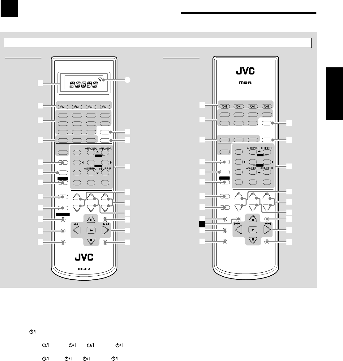
3
Français
Identification des parties
1Uniquement pour le RX-8030VBK: Fenêtre d’affichage
• Quand le mode de télécommand est changé, il apparaît sur
l’affichage.
• L’indicateur de transmission de signal (A) s’allume quand
des signaux sont transmis.
2Touches (17, 46 – 48)
•Pour le RX-8030VBK:
CATV/DBS , VCR 1 , TV , AUDIO
•Pour le RX-7030VBK:
CATV/DBS , VCR , TV , AUDIO
3Touches de sélection de source (17, 18, 19, 23, 24, 37, 40)
•Pour le RX-8030VBK:
DVD MULTI, DVD, CD*, FM/AM*, VCR 1, VCR 2,
CDR*, TAPE/MD*, TV/DBS, VIDEO, PHONO*
•Pour le RX-7030VBK:
DVD MULTI, DVD, CD*, FM/AM*, TV/DBS, VCR,
TAPE/CDR*
* Quand vous appuyez sur une des touches de sélection de
source, l’ampli-tuner se met automatiquement sous tension.
4• Touche SURROUND (37)
• Touche DSP (39)
• Touche SURR (Surround)/DSP OFF (37, 39)
• Touche EX/ES (37)
5•Pour le RX-8030VBK: Touche CC CONVERTER (21)
•Pour le RX-7030VBK: Touche CD DISC (45)
6Touche MIDNIGHT MODE (20)
7Touche SOUND (22, 32, 33)
8Touche CATV/DBS CONTROL (47)
9Touche TV/VIDEO (46, 47)
p•Pour le RX-8030VBK: Touche CONTROL (44 – 46)
•Pour le RX-7030VBK: Touche VCR CONTROL (46)
qTouche REC PAUSE (45, 46, 48)
wTouche SLEEP (22)
eTouche ANALOG/DIGITAL INPUT (20)
rTouche ANALOG DIRECT (21)
t• Touches numériques pour commander le tuner (24)
• Touches numériques pour ajuster le son (32, 33)
• Touches numériques pour commander les appareils audio/
vidéo (44 – 48)
y• Touches CH (canaux) +/– (46 – 48)
• *Touches LEVEL +/– (32, 33, 44)
Les touches LEVEL +/– fonctionnent uniquement après avoir
appuyé sur SOUND puis sur les touches numériques
marquées d’un astérisque (*) sur la télécommande.
uTouches VOLUME +/– (18)
iTouches TV VOL (volume) +/– (46, 47)
oTouche MUTING (22)
;• Touches TUNING UP/DOWN (23)
• Touches de commande des appareils audio/vidéo
(44 – 46, 48)
3, 8, 7, 4/REW, FF/¢
aTouche DIMMER (22)
åUniquement pour le RX-7030VBK:
Touche TAPE/CDR CONTROL (45)
Télécommande
RX-8030VBK RX-7030VBK
+
−
+
−
+
−
231
564
89
7/P
0
+10
MENU
ENTER
BASS BOOST
TEST
∗
CENTER
∗
SUB WOOFER
∗
DIGITAL EQ
∗
SURR BACK
CH/
∗
LEVEL
TV VOL
/REW
DOWN — TUNING — UP
FF/
MUTING
DIMMER
VOLUME
CATV/DBS
CONTROL
TV/VIDEO
REC PAUSE
SLEEP
RETURN FM MODE 100+
CONTROL
REMOTE CONTROL
RM-SRX8030J
CATV/DBS VCR 1 TV AUDIO
DSP
OFF
DVD MULTI CD
CDR TAPE/MD
TV/DBS VIDEO PHONO
FM/AM
VCR 1 VCR 2
SURROUND
EX/ES
CC CONVERTER
SURR/DSP
ANALOG/DIGITAL
A/V CONTROL RECEIVER
INPUT
MIDNIGHT
MODE
DIRECT
ANALOG
DVD
u
i
1
3
4
9
p
q
w
t
;
a
10/0
y
2
SOUND
8
6
5
7
o
r
e
A
+
−
+
−
+
−
231
564
89
7/P
0+10
MENU
ENTER
TESTCD DISC ∗CENTER∗
SUB WOOFER
∗DIGITAL EQ ∗SURR BACK
CH/∗LEVEL
TV VOL
/REW
DOWN — TUNING — UP
FF/
MUTING
DIMMER
VOLUME
CATV/DBS
CONTROL
VCR
CONTROL TAPE/CDR
CONTROL
TV/VIDEO
REC PAUSE
SLEEP
RETURN FM MODE 100+
REMOTE CONTROL RM-SRX7030J
CATV/DBS VCR TV AUDIO
DSP
OFF
DVD MULTI CD
TAPE/CDR
ANALOG/DIGITAL
FM/AM
TV/DBS VCR
SURROUND
EX/ES
SURR/DSP
A/V CONTROL RECEIVER
INPUT
MIDNIGHT
MODE
DIRECT
ANALOG
DVD
u
i
3
4
9
p
q
w
t
;
a
10/0
y
2
SOUND
8
6
5
7
o
r
e
s
BASS BOOST
FR01-16_8030&7030[C]f.pm6 03.2.12, 6:00 PM3
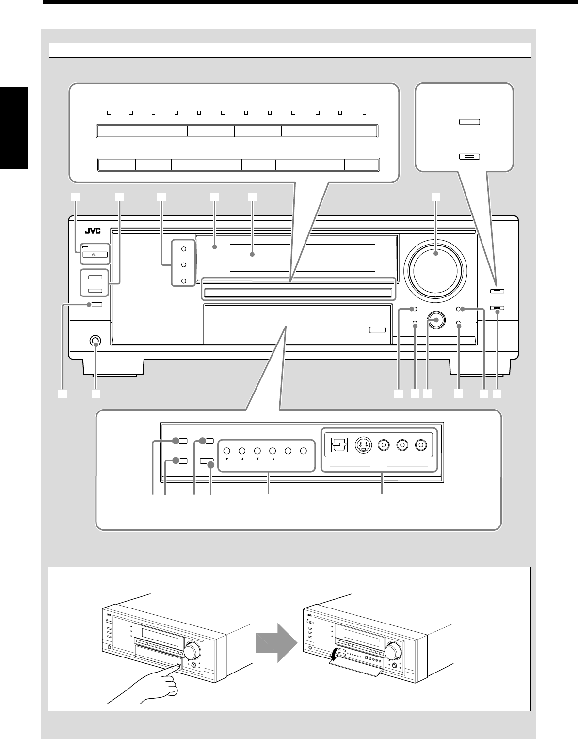
4
Français
Display Window
Panneau avant
Poussez vers le bas sur PUSH OPEN.
Comment ouvrir la porte avant
SUBWOOFER OUT ON/OFF
SPEAKERS ON/OFF
PHONES
1
STANDBY
ANALOG DIRECT
2
STANDBY/ON
TUNER CONTROL
SETTING ADJUST
QUICK SPEAKER
SETUP EXIT
MIDNIGHT
MODEEX / ES
INPUT ATT
INPUT
ANALOG
INPUT
DIGITAL
FM/AM TUNING FM/AM PRESET FM MODE MEMORY
SURROUND
DSP
SURROUND/ DSP
OFF
VIDEO
L—AUDIO—RDIGITAL S-VIDEO VIDEO PUSH SET
MULTI JOG
MASTER VOLUME
12
;s
ia
4 5 7
u o
p
9
3
PUSH OPEN
CC CONVERTER
BASS BOOST
8RX-8030VBK
RX-7030VBK
Uniquement pour le RX-8030VBK
Derrière la porte avant
TUNER CONTROL
MIDNIGHT
MODEEX / ES
INPUT ATT
INPUT
ANALOG
INPUT
DIGITAL
FM/AM TUNING FM/AM PRESET FM MODE MEMORY
VIDEO
L—AUDIO—RDIGITAL S-VIDEO VIDEO
r
eq wy
t
6
TV SOUND
/DBS
VIDEOVCR 2VCR 1
DVDDVD MULTI AMFMTAPE/MDCDRCDPHONO
TV SOUND/DBSVCR
DVDDVD MULTI AMFMTAPE/CDRCD
RX-8030VBK
RX-7030VBK
FR01-16_8030&7030[C]f.pm6 03.2.12, 6:00 PM4
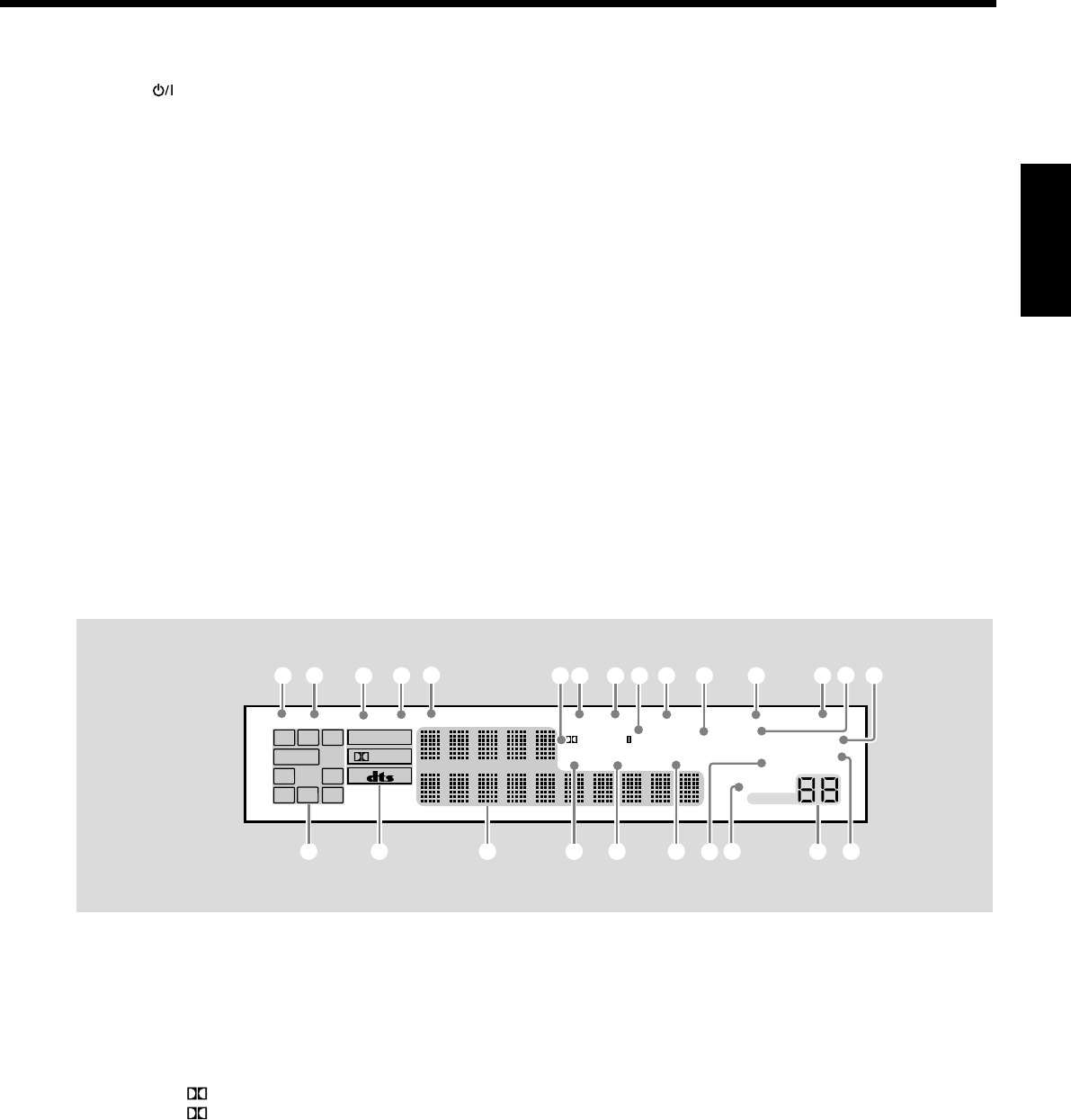
5
Français
Panneau avant
1Touche STANDBY/ON et témoin STANDBY (17)
2• Touche SPEAKERS ON/OFF 1 (19)
• Touche SPEAKERS ON/OFF 2 (19)
3• Touche SURROUND (37)
• Touche DSP (39)
• Touche SURROUND/DSP OFF (37, 39)
4Capteur de télécommande
5Fenêter d’affichage (17)
6•Pour le RX-8030VBK: Touches et témoins de sélection de
source (17, 18, 19, 21, 23, 24, 37, 40)
DVD MULTI, DVD, VCR 1, VCR 2, VIDEO,
TV SOUND/DBS, PHONO, CD, CDR, TAPE/MD, FM, AM
(Le témoin au-dessus de la source choisie s’allume.)
•Pour le RX-7030VBK: Touches de sélection de source
(17, 18, 19, 21, 23, 24, 37, 40)
DVD MULTI, DVD, VCR, TV SOUND/DBS, CD,
TAPE/CDR, FM, AM
7Réglage MASTER VOLUME (18)
8•Pour le RX-8030VBK:
Touche et témoin CC CONVERTER (21)
•Pour le RX-7030VBK: Touche et témoin BASS BOOST (22)
9Touche SUBWOOFER OUT ON/OFF (19)
pPrise PHONES (19)
qTouche EX/ES (37)
Fenêtre d’affichage
1Indicateur DUAL (35)
2Indicateur ANALOG (20)
3Indicateur DIGITAL AUTO (20)
4Indicateur 96/24 (35)
5Indicateur MULTI (40)
6• Indicateur PRO LOGIC (34)
• Indicateur PRO LOGIC II (35)
7Indicateur TUNED (23)
8Indicateur STEREO (23, 24)
9Indicateur NEO:6 (35)
0Indicateur AUTO MUTING (24)
w• Touche INPUT ANALOG (20)
• Touche INPUT ATT (20)
eTouche MIDNIGHT MODE (20)
rTouche INPUT DIGITAL (20)
tTouches TUNER CONTROL
• Touches FM/AM TUNING 5 / ∞ (23)
• Touches FM/AM PRESET 5 / ∞ (23, 24)
• Touche FM MODE (24)
• Touche MEMORY (23)
yUniquement pour le RX-8030VBK: Prises d’entrée
VIDEO (13)
Prise optique DIGITAL, prise S-VIDEO, prise VIDEO,
prises AUDIO—L/R
uTouche SETTING (27)
iTouche QUICK SPEAKER SETUP (25)
o• Réglage MULTI JOG (25, 27, 31)
• Touche PUSH SET (25, 27, 31)
;Touche EXIT (27, 31)
aTouche ADJUST (31)
sTouche et témoin ANALOG DIRECT (21)
-Indicateur VIRTUAL SB (Surround arrière) (34, 35)
=Indicateur ONE TOUCH OPERATION (30)
~Indicateur SLEEP (22)
!Indicateur MIDNIGHT MODE (20)
@Indicateur DIGITAL EQ (égalisation) (32)
#Indicateurs d’enceinte et de signal (18)
$Indicateurs de format de signal numérique (20)
%Affichage principal (17)
^Indicateur DSP (19, 38)
&Indicateur 3D-PHONIC (38)
*Indicateur HEADPHONE (19, 38)
(Indicateurs SPEAKERS 1/2 (19)
)Indicateur INPUT ATT (atténuateur) (20)
_Indicateur de niveau de VOLUME (17, 22)
+Indicateur BASS BOOST (22)
Fenêtre d’affichage
DIGITAL EQ
INPUT ATT
SLEEP
VOLUME
ONE TOUCH OPERATION
3D - PHONIC
NEO:6 VIRTUAL SB MIDNIGHT MODE
AUTO MUTING
TUNED STEREO
LINEAR PCM
DIGITAL
L
SUBWFR
LS RS
CR
S
LFE
DUAL DIGITAL AUTO
ANALOG 96/24 MULTI
PRO LOGIC
DSP
HEADPHONE SPEAKERS 1 2 BASS BOOST
SB
# $ % _
1 2 34567 8 0
9-= ~
+
^ & *
@
!
()
FR01-16_8030&7030[C]f.pm6 03.2.12, 6:00 PM5
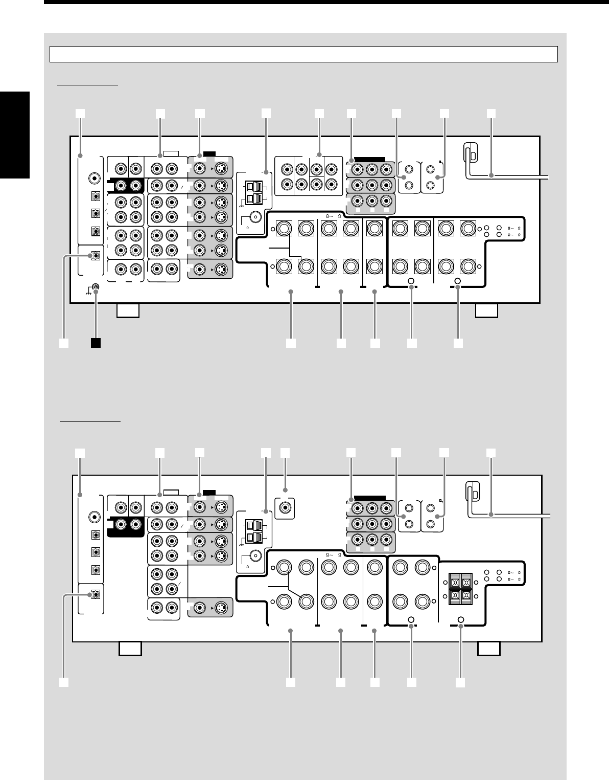
6
Français
Panneau arrière
RX-8030VBK
RX-7030VBK
VIDEO
RIGHT LEFT
L
R
L
R
S-VIDEO
VIDEO SURR BACK SURR CENTER FRONT
AUDIO
DIGITAL IN
DIGITAL 1 (DVD)
DIGITAL 2 (CD)
DIGITAL 3 (TV)
DIGITAL 4 (CDR)
PCM/ DOLBY DIGITAL
/ DTS
DIGITAL OUT
FM 75
COAXIAL
AM
EXT
AM
LOOP
RIGHT LEFT
+
–
+
–
12
CENTER
SPEAKER
SURROUND SPEAKERS
816
CAUTION : SPEAKER IMPEDANCE
MONITOR
OUT
SUBWOOFER CENTER
DVD
IN
OUT
(REC)
TAPE
MD
IN
(PLAY)
OUT
(REC)
CDR
IN
(PLAY)
PHONO
IN
FRONT
TV SOUND
DBS
IN
VCR 2
VCR 1
IN
(PLAY)
IN
(PLAY)
OUT
(REC)
OUT
(REC)
CD
IN
RIGHT LEFT
DVD
IN ANTENNA
SUBWOOFER
COMPONENT VIDEO
MONITOR
OUT
DBS
IN
DVD
IN
YPBPR
COMPU LINK-4
(SYNCHRO)
AV
COMPULINK-
SURROUND BACK SPEAKERS
FRONT SPEAKERS
RIGHT LEFT RIGHT LEFT RIGHT LEFT
CAUTION : SPEAKER IMPEDANCE
SINGLE USE
See Instruction
Manual For
Connection
1
OR
2 :
816
1
AND
2 :
16 32
PREOUT
SURR
(REAR)
12
3456789
trewq
py
VIDEO
RIGHT LEFT S-VIDEO
VIDEO
AUDIO
DIGITAL IN
DIGITAL 1 (DVD)
DIGITAL 2 (CD)
DIGITAL 3 (TV)
DIGITAL 4 (CDR)
PCM/ DOLBY DIGITAL
/ DTS
DIGITAL OUT
FM 75
COAXIAL
AM
EXT
AM
LOOP
RIGHT LEFT
+
–
+
–
12
CENTER
SPEAKER
SURROUND SPEAKERS
816
CAUTION : SPEAKER IMPEDANCE
MONITOR
OUT
SUBWOOFER CENTER
DVD
IN
SURR
(REAR)
TAPE
CDR
FRONT
TV SOUND
DBS
IN
VCR
IN
(PLAY)
IN
(PLAY)
OUT
(REC)
OUT
(REC)
CD
IN
RIGHT LEFT
DVD
IN ANTENNA
COMPONENT VIDEO
MONITOR
OUT
DBS
IN
DVD
IN
YP
B
P
R
COMPU LINK-4
(SYNCHRO)
AV
COMPULINK-
SURROUND BACK SPEAKERS
RIGHT LEFT RIGHT LEFT
RIGHT LEFT
CAUTION : SPEAKER IMPEDANCE
SINGLE USE
See Instruction
Manual For
Connection
1
OR
2 :
816
1
AND
2 :
16 32
SUBWOOFER
OUT
+ +
– –
123456789
reqp w
FRONT SPEAKERS
t
FR01-16_8030&7030[C]f.pm6 03.2.12, 6:00 PM6

7
Français
Panneau arrière
RX-8030VBK
1Prises DIGITAL IN (16)
• Coaxiale: DIGITAL 1 (DVD)
• Optique: DIGITAL 2 (CD), DIGITAL 3 (TV),
DIGITAL 4 (CDR)
2Prises d’entrée/sortie AUDIO (11 – 15)
• Entrée: DVD IN—FRONT, CENTER, SUBWOOFER,
SURR (REAR), TV SOUND/DBS IN,
VCR 1 IN (PLAY), VCR 2 IN (PLAY), CD IN,
TAPE/MD IN (PLAY), CDR IN (PLAY),
PHONO IN
• Sortie: VCR 1 OUT (REC), VCR 2 OUT (REC),
TAPE/MD OUT (REC), CDR OUT (REC)
3Prises d’entrée/sortie S-VIDEO et VIDEO composite (14, 15)
• Entrée: DVD IN, TV SOUND/DBS IN, VCR1 IN (PLAY),
VCR 2 IN (PLAY)
• Sortie: VCR 1 OUT (REC), VCR 2 OUT (REC),
MONITOR OUT
4Prises FM/AM ANTENNA (8)
5Prises PREOUT (10, 11)
• FRONT, CENTER, SUBWOOFER, SURR, SURR BACK
6Prises d’entrée/sortie en composantes vidéo (COMPONENT
VIDEO) (14, 15)
• Entrée: DVD IN, DBS IN
• Sortie: MONITOR OUT
7Prises COMPU LINK-4 (SYNCHRO) (41)
8Prises AV COMPULINK-III (42)
9Cordon d’alimentation secteur (16)
pPrise DIGITAL OUT (16)
qPrises SURROUND BACK SPEAKERS (10)
wPrises SURROUND SPEAKERS (10)
ePrises CENTER SPEAKER (10)
rPrises FRONT SPEAKERS 1 (10)
tPrises FRONT SPEAKERS 2 (10)
ÔPrise de mise à la terre (11)
RX-7030VBK
1Prises DIGITAL IN (16)
• Coaxiale: DIGITAL 1 (DVD)
• Optique: DIGITAL 2 (CD), DIGITAL 3 (TV),
DIGITAL 4 (CDR)
2Prises d’entrée/sortie AUDIO (12 – 15)
• Entrée: DVD IN—FRONT, CENTER, SUBWOOFER,
SURR (REAR), TV SOUND/DBS IN,
VCR IN (PLAY), TAPE/CDR IN (PLAY), CD IN
• Sortie: VCR OUT (REC), TAPE/CDR OUT (REC)
3Prises d’entrée/sortie S-VIDEO et VIDEO composite (14, 15)
• Entrée: DVD IN, TV SOUND/DBS IN, VCR IN (PLAY)
• Sortie: VCR OUT (REC), MONITOR OUT
4Prises FM/AM ANTENNA (8)
5Prise SUBWOOFER OUT (10)
6Prises d’entrée/sortie en composantes vidéo (COMPONENT
VIDEO) (14, 15)
• Entrée: DVD IN, DBS IN
• Sortie: MONITOR OUT
7Prises COMPU LINK-4 (SYNCHRO) (41)
8Prises AV COMPULINK-III (42)
9Cordon d’alimentatio secteur (16)
pPrise DIGITAL OUT (16)
qPrises SURROUND BACK SPEAKERS (10)
wPrises SURROUND SPEAKERS (10)
ePrises CENTER SPEAKER (10)
rPrises FRONT SPEAKERS 1 (10)
tPrises FRONT SPEAKERS 2 (10)
RX-8030VBK
RX-7030VBK
Prises PREOUT
嘷
⳯
Prises vidéo (entrée/sortie)
Vidéo composite (4/3)
S-vidéo (4/3)
Composantes vidéo (2/1)
Vidéo composite (3/2)
S-vidéo (3/2)
Composantes vidéo (2/1)
Convertisseur CC
嘷
⳯
Sources sélectionnables
DVD MULTI, DVD, VCR 1, VCR 2, VIDEO,
TV SOUND/DBS, PHONO, CD, CDR, TAPE/MD,
FM, AM
DVD MULTI, DVD, VCR,
TV SOUND/DBS, CD, TAPE/CDR, FM, AM
嘷: Fourni ⳯: Non fourni
Différences entre le RX-8030VBK et le RX-7030VBK
Télécommande Fenêtre d’affichage Couleur
RM-SRX8030J 嘷Noir
RM-SRX7030J ⳯Noir
FR01-16_8030&7030[C]f.pm6 03.2.12, 6:00 PM7
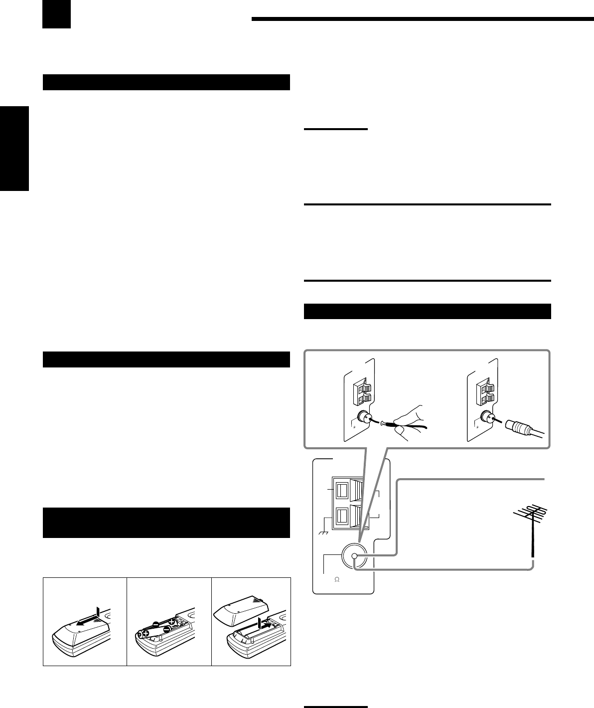
8
Français
Si la télécommande ne peut pas transmettre les signaux ou ne
commande pas correctement l’ampli-tuner, remplacez les piles.
Utilisez deux piles sèches de type R6P(SUM-3)/AA(15F).
Remarques:
•Les piles fournies sont uniquement pour les réglages initiaux.
Remplacez-les pour continuer à utiliser l’appareil.
•Après le remplacement des piles, réglez à nouveau les codes des
fabricants (voir pages 47 à 49).
ATTENTION:
Suivez ces précautions pour éviter toute fuite ou fissuration des piles:
•Placer les piles dans la télécommande de façon que la polarité soit
respectée: (+) à (+) et (–) à (–).
•Utilisez le type de pile correct. Des piles qui paraissent similaires
peuvent différer en tension.
•Remplacez toujours les deux piles en même temps.
•N’exposez pas les piles à la chaleur ou à une flamme.
Connexion des antennes FM et AM
Connexion de l’antenne FM
A. Utilisation de l’antenne FM fournie
L’antenne FM fournie peut être connectée à la prise FM 75 Ω
COAXIAL de façon temporaire.
B. Utilisation d’un connecteur de type standard (non fourni)
Un connecteur de type standard devrait être connecté à la prise
FM 75 Ω COAXIAL.
Remarque:
Si la réception est mauvaise, connectez une antenne FM extérieure
(non fourni). Avant de connecter un câble coaxial 75
Ω
muni d’un
connecteur (câble rond provenant de l’antenne extérieure),
déconnectez l’antenne-fil FM fournie.
FM 75
COAXIAL
AM
EXT
AM
LOOP
ANTENNA
FM 75
COAXIAL
ANTENNA
FM 75
COAXIAL
ANTENNA
Pour commencer
Cette section explique comment connecter les appareils audio/vidéo et les enceintes à l’ampli-tuner, et comment
connecter l’appareil au secteur.
Avant l’installation
Général
•Assurez-vous d’avoir les mains sèches.
•Mettez tous les appareils hors tension.
•Lisez les modes d’emploi fournis avec les appareils qui doivent
être connectés.
Emplacement
•Installez l’ampli-tuner dans un endroit plat et protégé de
l’humidité.
•La température autour de l’ampli-tuner doit être comprise entre
–5˚C et 35˚C (23˚F et 95˚F).
•Assurez-vous qu’il y a une bonne ventilation autour de l’appareil.
Une mauvaise ventilation peut entraîner une surchauffe et
endommager l’ampli-tuner.
Manipulation de l’ampli-tuner
•N’insérez aucun objet métallique à l’intérieur de l’ampli-tuner.
•Ne démontez pas l’ampli-tuner ni ne retirez les vis, les couvercles
ou le compartiment.
•N’exposez pas l’appareil à la pluie ou à l’humidité.
Vérification des accessoires fournis
Vérifiez que tous les articles suivants sont bien fournis avec
l’ampli-tuner.
Le nombre entre parenthèses indique la quantité d’articles fournis.
• Télécommande (1)
• Piles (2)
• Antenne cadre AM (1)
• Antenne FM (1)
Si quelque chose manquait, contacter le revendeur immédiatement.
Mise en place des piles dans la
télécommande
Avant d’utiliser la télécommande, mettez en place les deux piles
fournies.
1. Appuyez sur le couvercle au dos de la
télécommande et faites le glisser pour le retirer.
2. Insérez les piles.
•Respectez les polarités: (+) à (+) et (–) à (–).
3. Remettez le couvercle en place.
B
Antenne FM (fournie)
Câble d’antenne FM
extérieure (non fourni)
Etendez l’antenne FM fournie
horizontalement.
A
12
R6P(SUM-3)/
AA(15F)
3
FR01-16_8030&7030[C]f.pm6 03.2.12, 6:00 PM8
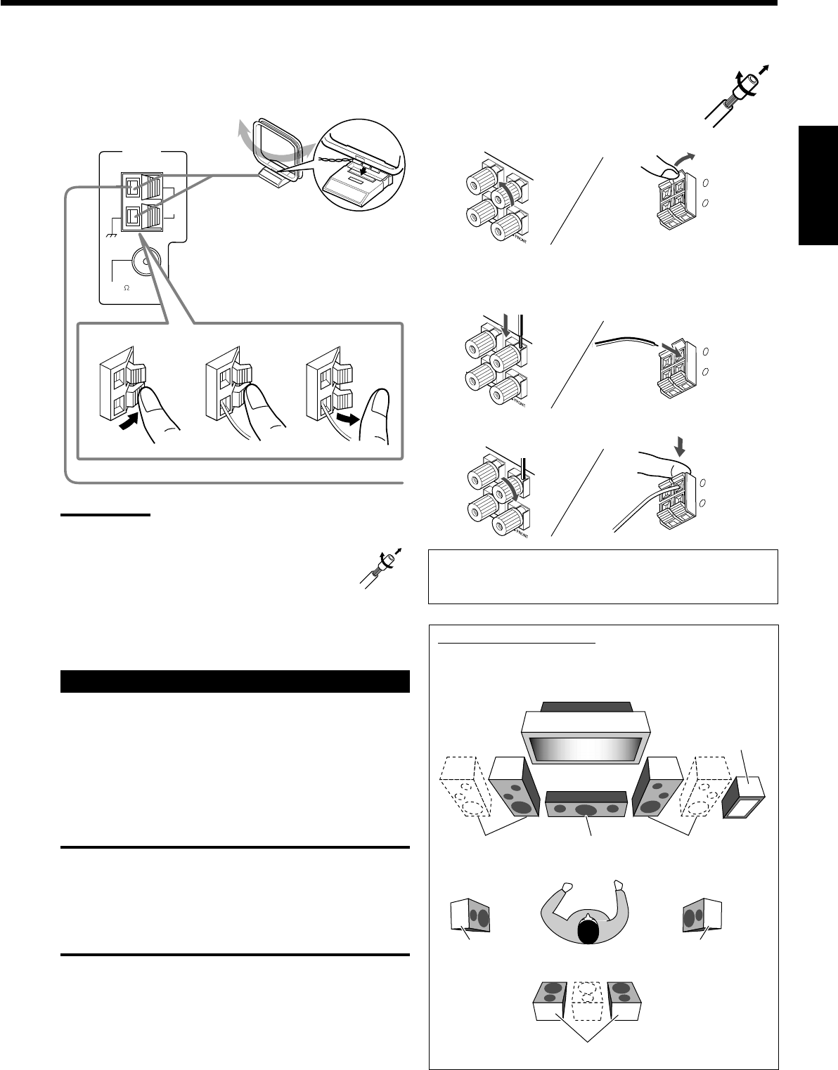
9
Français
Connexion de l’antenne AM
Tourner le cadre jusqu’à l’obtention
de la meilleure réception.
Antenne cadre AM
(fournie)
Insérer les languettes du cadre dans les
fentes de la base pour assembler
l’antenne cadre AM.
Fil extérieur recouvert de vinyle (non fourni)
Remarques:
•Si le fil de l’antenne cadre AM est recouvert de vinyle, retirez ce
dernier en le tordant comme montré sur l’illustration ci-
contre.
•Assurez-vous que les conducteurs de l’antenne ne
touchent aucune autre prise, cordon de connexion et
cordon d’alimentation. Cela pourrait nuire à la réception.
•Si la réception est mauvaise, connectez un fil extérieur recouvert
de vinyle (non fourni) à la prise AM EXT. (Laissez l’antenne cadre
AM connectée.)
Connexion des enceintes
Vous pouvez connecter les enceintes suivantes:
•Deux paires d’enceintes avant pour produire un son stéréo normal.
•Une paire d’enceintes Surround pour profiter des effets Surround.
•Une enceinte Surround arrière ou une paire d’enceintes Surround
arrière pour obtenir un effet Surround plus efficace.
•Une enceinte centrale pour accentuer les voix humaines.
•Un caisson de grave pour améliorer les graves.
ATTENTION:
Utilisez uniquement des enceintes dont l’impédance correspond à
l’impédance (SPEAKER IMPEDANCE) indiquée sur les prises
d’enceintes.
•Quand vous utilisez les deux prises FRONT SPEAKERS 1 et
2, utilisez des enceintes d’une impédance de 16 Ω à 32 Ω.
•Quand vous n’utilisez qu’une seule prise, FRONT SPEAKERS
1 ou 2, utilisez des enceintes d’une impédance de 8 Ω à 16 Ω.
RIGHT LEFT
RIGHTLEFT
RIGHTLEFT
+
–
RIGHTLEFT
Procédure de connexion de base
1 Tordez et retirez l’isolant à
l’extrémité de chaque câble de
signal d’enceinte (non fourni).
2 Ouvrez la prise d’enceinte.
RX-7030VBK
(Pour les prises FRONT SPEAKERS 2)
3 Insérez le câble de signal d’enceinte.
4 Refermez la prise d’enceinte.
Pour chaque enceinte (à l’exception du caisson de grave),
connectez les prises (+) et (–) du panneau arrière aux prises
marquées (+) et (–) sur les enceintes.
Caisson de
grave
Disposition des enceintes
La position idéale des enceintes varie en fonction des conditions
de la pièce où vous les installez. Le schéma suivant est exemple
de disposition recommandée.
Enceinte(s) avant
gauche (L)
Enceinte(s) avant
droite (R)
Enceinte
centrale (C)
Enceintes Surround arrière (LSB/RSB)
Enceinte Surround
gauche (LS) Enceinte Surround
droite (RS)
+
–
RIGHTLEFT
FM 75
COAXIAL
AM
EXT
AM
LOOP
ANTENNA
23
1
+
–
RIGHT LEFT
FR01-16_8030&7030[C]f.pm6 03.2.12, 6:00 PM9
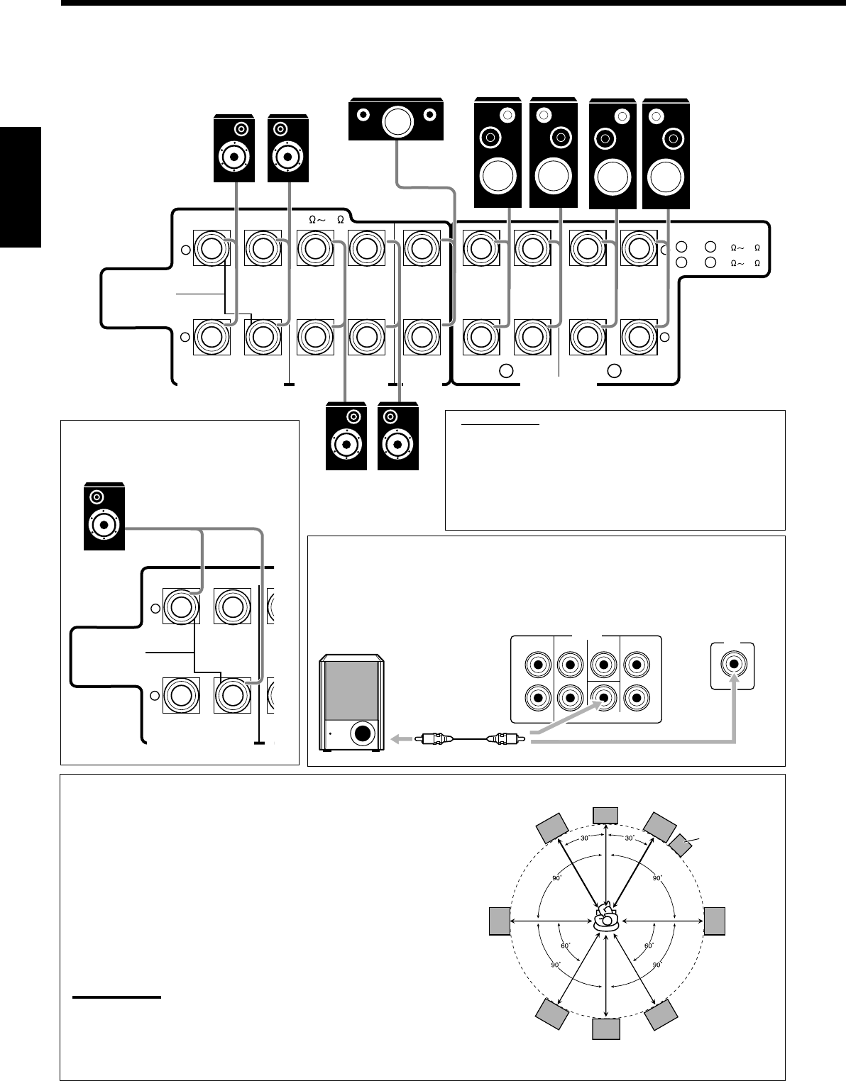
10
Français
Disposition des enceintes
Enceintes avant et enceinte centrale
•Placez ces enceintes (position du haut-parleur des médiums) à la même
hauteur que le son.
•Dirigez ces enceintes vers les oreilles de l’auditeur.
Enceintes Surround et Surround arrière
•Placez ces enceintes à plus d’un mètre au-dessus des oreilles de l’auditeur.
•Dirigez ces enceintes vers le bas vers les oreilles de l’auditeur.
Caisson de grave
•Vous pouvez le placer ou vous le souhaitez puisque les sons graves ne sont
pas directionnels. Normalement, placez-le devant vous.
Remarque:
Pour obtenir la position idéale des enceintes, il faut que toutes les enceintes soient
placés à la même distance de l’auditeur. Cependant, puisqu’il est difficile dans certains
endroits de remplir ces exigences, cet appareil peut être réglé de façon à retarder le son
provenant de chaque enceinte de façon qu’il atteigne l’auditeur en même temps. (Voir
page 28.)
Caisson de
grave
IMPORTANT:
Après avoir connecté les enceintes, réglez correctement
les informations d’installation des enceintes. Vous
pouvez utiliser la configuration rapide des enceintes
pour régler facilement les informations d’installation des
enceintes (voir page 25).
•Pour obtenir le meilleur effet Surround/DSP possible,
référez-vous à “Réglage des enceintes” à la page 27.
Enceintes avant 1
droite / gauche
Enceintes Surround arrière*
droite / gauche
Enceintes avant 2
droite / gauche
Enceinte
centrale
*
Lors de l’utilisation d’une
seule enceinte Surround
arrière, connectez le
cordon
ª
à la prise
RIGHT
ª
et le cordon
·
à la prise LEFT
·
.
Enceintes arrière
droite / gauche
RIGHT LEFT
+
–
+
–
CENTER
SPEAKER
SURROUNDSPEAKERS
816
CAUTION : SPEAKER IMPEDANCE
SURROUND BACK SPEAKERS
FRONT SPEAKERS
RIGHT LEFT RIGHT LEFT RIGHT LEFT
CAUTION : SPEAKER IMPEDANCE
SINGLE USE
See Instruction
Manual For
Connection
1
OR
2 :
816
1
AND
2 :
16 32
1 2
Connexion d’un caisson de grave
Vous pouvez améliorer les graves en connectant un caisson de grave.
Connectez la prise d’entrée d’un caisson de grave au panneau arrière en utilisant un
câble à fiches cinch (non fourni).
L
R
L
R
SURR BACK SURR CENTER FRONT
SUBWOOFER
PREOUT
SUBWOOFER
OUT
RX-7030VBK
RX-8030VBK
RIGHT LEFT
+
–
S
U
8
CAUTION : SPEAKER IMPEDANCE
SURROUND BACK SPEAKERS
SINGLE USE
See Instruction
Manual For
Connection
C
LR
LS RS
LSB RSB
SB*
* Quand une enceinte Surround arrière
est connectée.
•Les prises arrières du RX-8030VBK sont utilisées pour l’explication.
FR01-16_8030&7030[C]f.pm6 03.2.12, 6:00 PM10
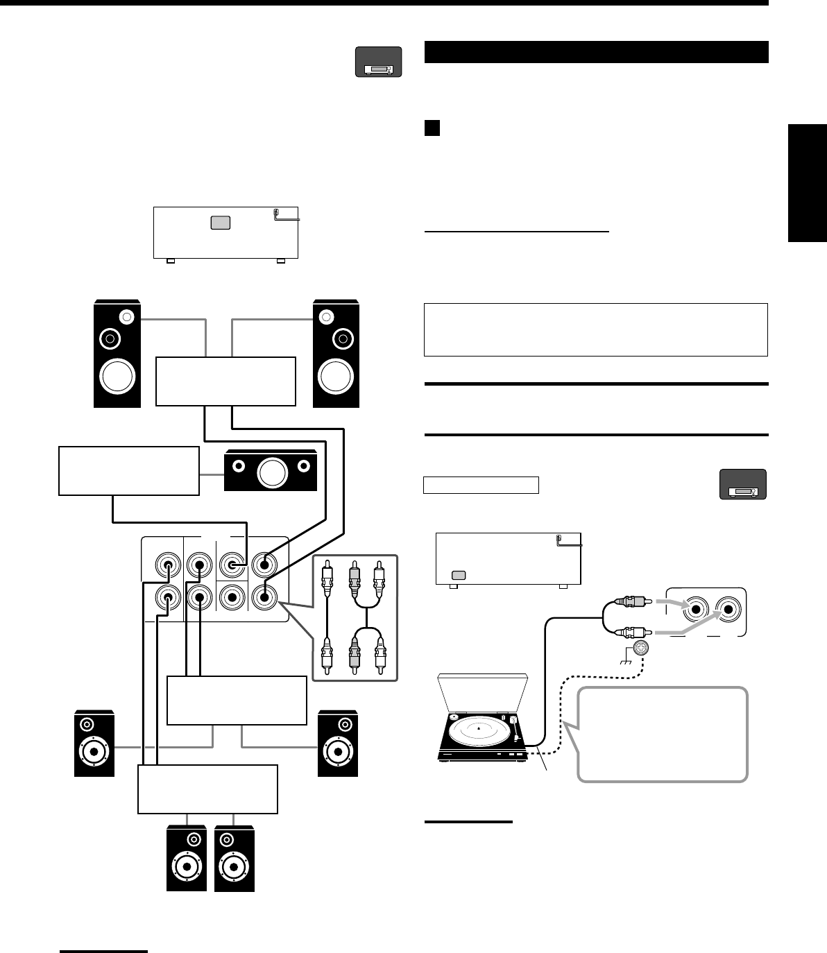
11
Français
Amélioration de votre système audio
—Uniquement pour le RX-8030VBK
Vous pouvez utiliser cet ampli-tuner comme un préamplificateur
(amplificateur de commande) quand vous connectez des
amplificateurs de puissance aux prises PREOUT sur le panneau
arrière en utilisant des câbles muni de fiches cinch (non fournis).
•Connectez la fiche blanche à la prise audio gauche et la fiche
rouge à la prise audio droite.
Remarque:
Si vous ne connectez qu’une enceinte Surround arrière, connectez
l’enceinte Surround arrière à la prise PREOUT Surround arrière
gauche.
PHONO
IN
RIGHT LEFT
R
L
RX-8030VBK
RX-8030VBK
L
R
L
R
SURR BACK SURR CENTER FRONT
SUBWOOFER
PREOUT
RL
RL
Connexion des appareils audio/vidéo
Lors de la connexion de composants individuels, référez-vous aussi
aux modes d’emploi qui les accompagnent.
Connexions analogiques
Si votre appareil audio est muni d’une prise de sortie audio
numérique, la connecter en utilisant un cordon numérique comme
expliqué dans la section “Connexions numériques” (voir page 16)
vous permettra d’obtenir un son de meilleur qualité.
Connexion des appareils audio
Utiliser des câbles munis de fiches cinch (non fournis).
•Connecter la fiche blanche à la prise audio gauche et la fiche
rouge à la prise audio droite.
Si vos appareils audio possèdent une prise COMPU LINK
Référez-vous aussi à la page 41 pour plus d’informations sur la
connexion et le système de commande à distance COMPU LINK.
ATTENTION:
Si vous connectez un appareil d’amélioration du son tel qu’un
égaliseur graphique entre l’appareil source et cet ampli-tuner, la sortie
sonore à travers cet ampli-tuner risque d’être déformée.
Tourne-disque
Pour écouter le son après la connexion, appuyez sur PHONO.
Si le tourne-disque est
muni d’un câble de mise à
la terre, connecter ce
câble à la vis de terre (H)
sur le panneau arrière.
Remarque:
Cette connexion est pour un tourne-disque à cellule de type MM (à
aimant mobile).
Les tourne-disques incorporant une cellule à faible signal de sortie
telle qu’une MC (type à bobine mobile) doivent être connectés à
l’ampli-tuner à travers un amplificateur de tête ou un amplificateur
élévateur disponible dans le commerce. Une connexion directe
résulterait en un volume insuffisant.
Amplificateur de
puissance
Enceinte avant gauche Enceinte avant droite
Amplificateur de
puissance
Enceinte
Surround
droite
Enceinte
Surround
gauche
Amplificateur de
puissance
Amplificateur de
puissance
Enceinte centrale
À la sortie audio
Tourne-disque
RX-8030V
ONLY
RX-8030V
ONLY
Enceintes Surround arrière
gauche / droite
FR01-16_8030&7030[C]f.pm6 03.2.12, 6:01 PM11
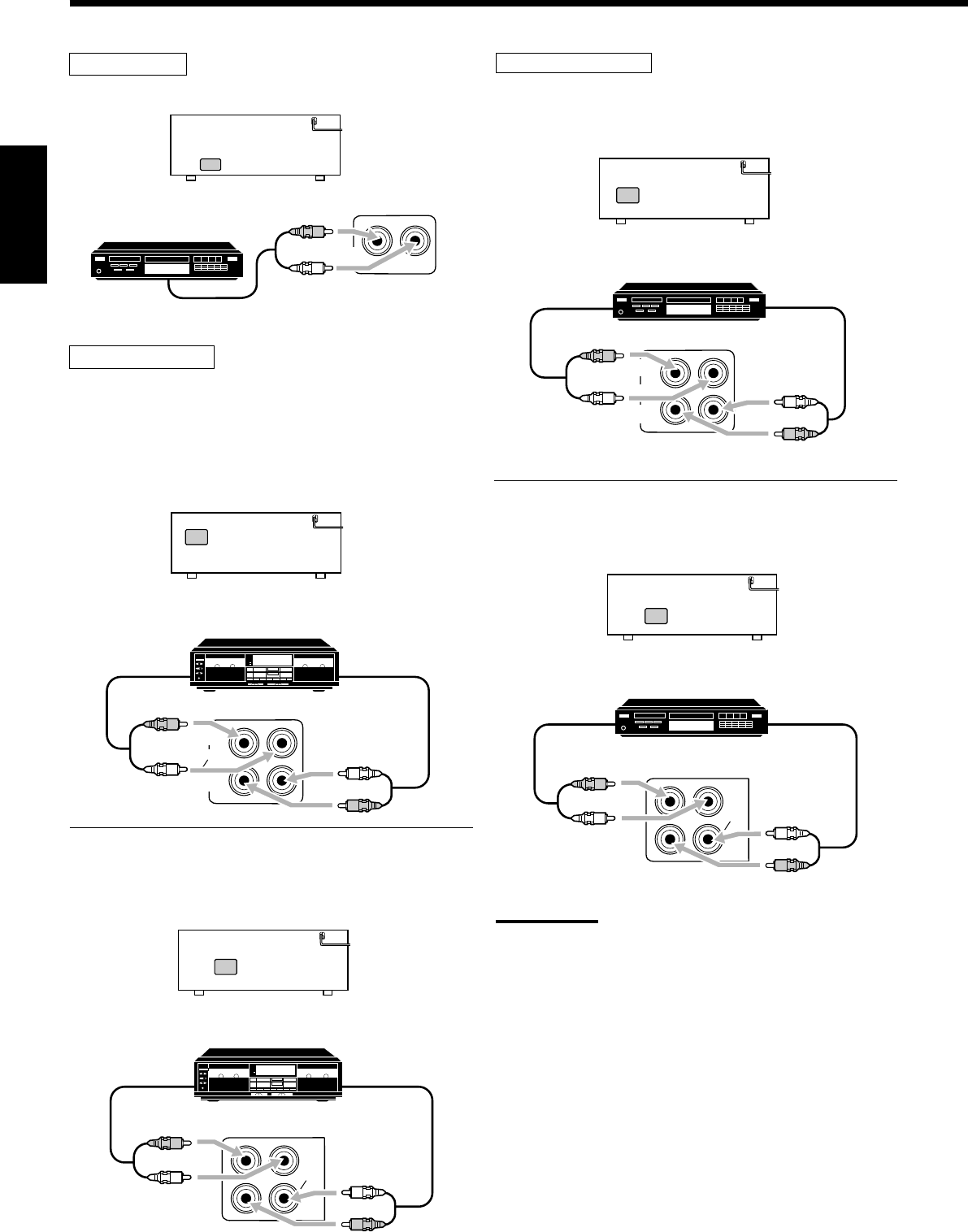
12
Français
Lecteur CD
Pour écouter le son après la connexion, appuyez sur CD.
Platine cassette
Pour écouter le son après la connexion, appuyez sur TAPE/MD
(pour le RX-8030VBK) ou sur TAPE/CDR (pour le RX-7030VBK).
Pour le RX-8030VBK
Vous pouvez connecter une platine cassette ou un enregistreur de
MD aux prises TAPE/MD. Pour la connexion d’un enregistreur de
MD, référez-vous à la page 13.
Pour le RX-7030VBK
Vous pouvez connecter une platine cassette ou un enregisteur de CD
aux prises TAPE/CDR. Pour la connexion d’un enregistreur de CD
au prises TAPE/CDR, référez-vous à la colonne de droite.
CD
IN
R
L
RX-8030VBK/RX-7030VBK
OUT
(REC)
TAPE
MD
IN
(PLAY)
RX-8030VBK
R
L
R
L
Enregistreur de CD
Pour écouter le son après la connexion, appuyez sur CDR (pour le
RX-8030VBK) ou sur TAPE/CDR (pour le RX-7030VBK).
Pour le RX-8030VBK
Pour le RX-7030VBK
Vous povuez connecter un enregistreur de CD ou une platine
cassette aux prises TAPE/CDR. Pour la connexion d’une platine
cassette aux prises TAPE/CDR, référez-vous à la colonne de gauche.
Remarque:
Pour le RX-7030VBK: Lors de la connexion d’un enregistreur de CD
aux prises TAPE/CDR, changez le nom de la source sur “CDR” qui
apparaîtra sur l’affichage que la source est choisie. Référez-vous à la
page 21 pour les détails.
À la sortie audio
À l’entré audio
Platine cassette
À la sortie audio
À l’entrée audio
Platine cassette
RX-7030VBK
TAPE
CDR
IN
(PLAY)
OUT
(REC)
R
L
R
L
RX-8030VBK
OUT
(REC)
CDR
IN
(PLAY)
R
L
R
L
À la sortie audio
À l’entrée audio
Enregistreur de CD
À la sortie audio
À l’entrée audio
Enregistreur de CD
À la sortie
audio
Lecteur CD
TAPE
CDR
IN
(PLAY)
OUT
(REC)
RX-7030VBK
R
L
R
L
FR01-16_8030&7030[C]f.pm6 03.2.12, 6:01 PM12
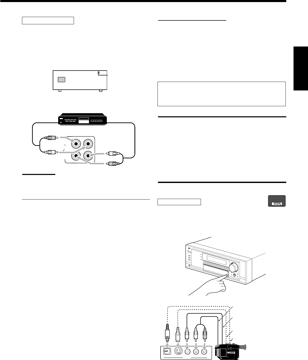
13
Français
Enregistreur de MD
Pour écouter le son après la connexion, appuyez sur TAPE/MD
(pour le RX-8030VBK) ou sur TAPE/CDR (pour le RX-7030VBK).
Pour le RX-8030VBK
Vous pouvez connecter un enregistreur de MD ou une platine
cassette aux prises TAPE/MD. Pour la connexion d’une platine
cassette, référez-vous à la page 12.
Remarque:
Lors de la connexion d’un enregistreur de MD aux prises TAPE/MD,
changer le nom de la source sur “MD”, qui apparaîtra sur l’affichage
lors de la sélection de la source. Référez-vous à la page 21 pour les
détails.
Pour le RX-7030VBK
Vous pouvez connecter un enregistreur de MD aux prises TAPE/
CDR si elles ne sont pas utilisées pour la connexion d’un autre
appareil tel qu’une platine cassette ou un enregistreur de CD. Pour la
connexion d’un enregisteur de MD aux prises TAPE/CDR, référez-
vous à la page 12.
•Même si vous enregistreur de MD est un appareil JVC muni du
système de commande à distance COMPU LINK, vous ne pouvez
pas utiliser le système de commande à distance pour commander
l’enregistreur de MD.
OUT
(REC)
TAPE
MD
IN
(PLAY)
RX-8030VBK
R
L
R
L
À la sortie audio
À l’entrée audio
Enregistreur de MD
Connexion des appareils vidéo
Utilisez des câbles munis de fiches cinch (non fournis).
Connectez la fiche blanche à la prise audio gauche, la prise rouge à
la fiche audio droite et la fiche jaune à prise vidéo.
•Si les appareils vidéo possèdent des prises S-vidéo (séparation
Y/C) et/ou en composantes vidéo (Y, PB, PR), connectez-les en
utilisant un câble S-vidéo (non fourni) et/ou un câble en
composantes vidéo (non fourni). En utilisant ces prises, vous
pouvez obtenir une meilleure qualité vidéo dans l’ordre suivant —
Composantes vidéo > S-vidéo > Vidéo composite.
Si votre appareil vidéo est muni d’une prise AV COMPULINK
Référez-vous aussi à la page 42 pour des informations détaillées
sur la connexion et le système de commande à distance AV
COMPU LINK .
IMPORTANT:
Cet ampli-tuner est muni des prises vidéo suivantes—vidéo
composite, S-vidéo et composantes vidéo. Vous pouvez les utiliser
sans distinction pour connecter un appareil vidéo.
Cependant, notez que les signaux vidéo d’un type de prises
d’entrée ne sont sortis que par le même type de prise de sortie.
Par conséquent, si un appareil d’enregistrement vidéo et un appareil
de lecture vidéo sont connectés à l’ampli-tuner par des prises vidéo
de type différent, vous ne pouvez pas enregistrer l’image de l’appareil
de lecture sur l’appareil d’enregistrement. De plus, si le téléviseur et
l’appareil de lecture vidéo sont connectés à l’ampli-tuner par des
prises vidéo de type différent, vous ne pouvez pas voir l’image de
lecture de l’appareil de lecture vidéo sur le téléviseur.
Caméra vidéo
Pour écouter le son après la connexion, appuyez sur VIDEO.
Les prises d’entrée VIDEO sur le panneau avant (derrière la porte
avant) sont pratiques pour la connexion et déconnexion fréquente
d’un appareil.
S-VIDEODIGITAL VIDEO L—AUDIO—R
VIDEO
R
L
À la sortie vidéo
composite
À la sortie S-Vidéo
À la sortie numérique
optique
À la sortie audio
Caméra vidéo
Lors de l’utilisation de la prise d’entrée numérique
Choisissez le mode d’entrée numérique correctement.
Pour les détails, référez-vous à “Sélection du mode d’entrée
analogique ou numérique” à la page 19.
RX-8030V
ONLY
FR01-16_8030&7030[C]f.pm6 03.2.12, 6:01 PM13
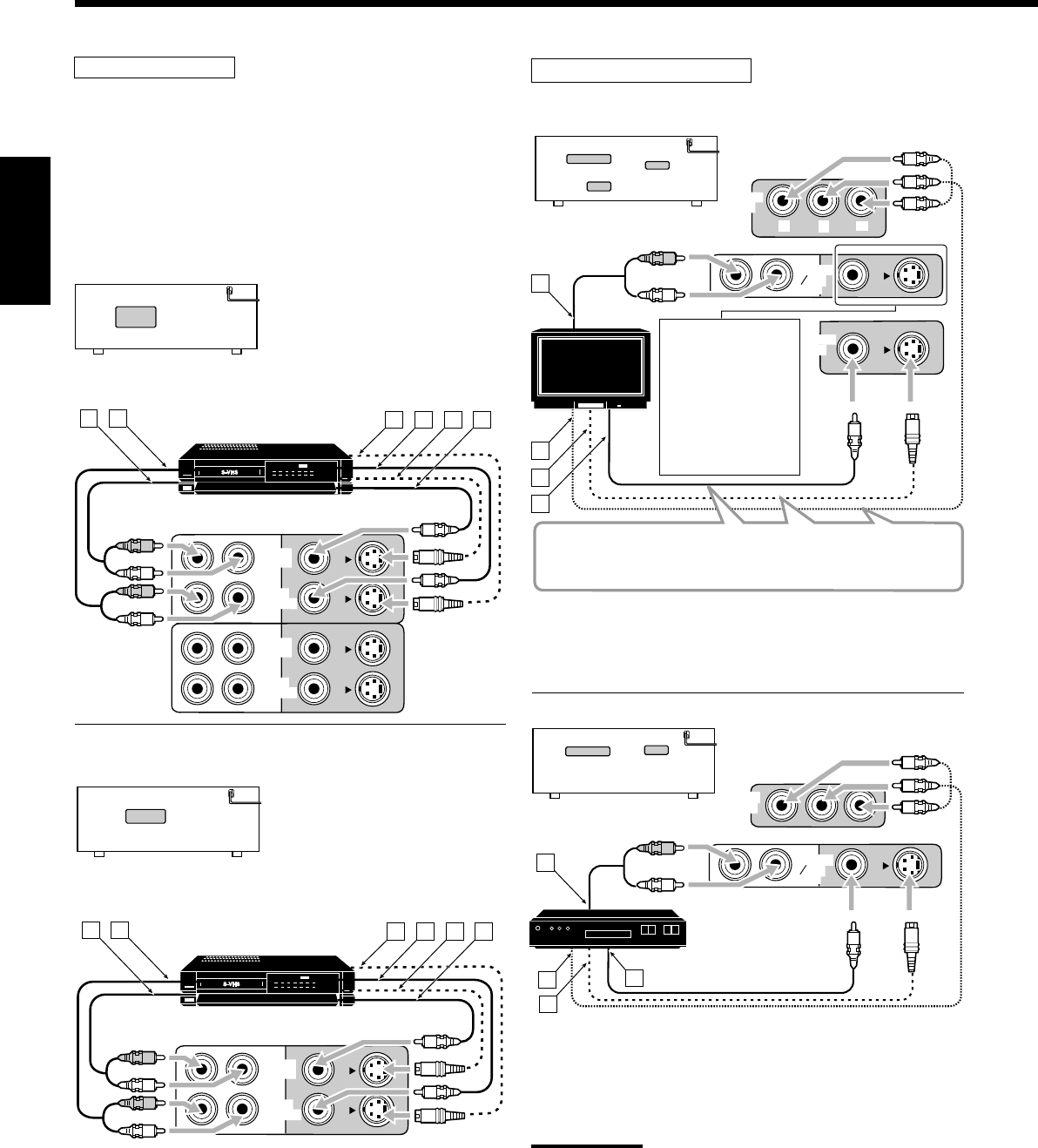
14
Français
Magnétoscope(s)
Pour écouter le son après la connexion, appuyez sur VCR 1 ou VCR
2 (pour le RX-8030VBK) ou sur VCR (pour le RX-7030VBK).
Pour le RX-8030VBK
Vous pouvez connecter deux magnétoscope—un aux prises VCR 1
et l’autre aux prises VCR 2.
•Si votre magnétoscope est muni d’une prise AV COMPU LINK,
connectez-le aux prises VCR 1 de façon à pouvoir utiliser le
système de commande à distance AV COMPU LINK.
ÅÀ l’entrée audio
ıÀ la sortie audio
ÇÀ la sortie S-Vidéo
ÎÀ la sortie vidéo composite
‰À l’entrée S-Vidéo
ÏÀ l’entrée vidéo composite
Pour le RX-7030VBK
ÅÀ l’entrée audio
ıÀ la sortie audio
ÇÀ la sortie S-Vidéo
ÎÀ la sortie vidéo composite
‰À l’entrée S-vidéo
ÏÀ l’entrée vidéo composite
RX-8030VBK
VCR 2
VCR 1
IN
(PLAY)
IN
(PLAY)
OUT
(REC)
OUT
(REC)
A B DC E F
R
L
R
L
RX-7030VBK
VCR
IN
(PLAY)
OUT
(REC)
A B DC E F
R
L
R
L
Téléviseur et/ou tuner DBS
Pour écouter le son après la connexion, appuyez sur TV SOUND/
DBS (ou sur TV/DBS sur la télécommande).
TV
Tuner DBS
ÅÀ la sortie audio
ıÀ l’entrée en composantes vidéo
ÇÀ l’entrée S-Vidéo
ÎÀ l’entrée vidéo composite
Lors de la connexion
du téléviseur aux
prises jacks AUDIO
(TV SOUND/DBS
IN), NE connectez
pas la sortie vidéo du
téléviseur à ces
prises d’entrée vidéo.
ÅÀ la sortie audio
ıÀ la sortie en composantes vidéo
ÇÀ la sortie S-Vidéo
ÎÀ la sortie vidéo composite
Remarques:
•Lors de la connexion d’un tuner DBS aux prises TV SOUND/DBS
IN, changez le nom de la source sur “DBS”, qui apparaîtra sur
l’affichage lors de la sélection de la source. Sinon, vous ne pourrez
pas voir l’image du tuner DBS. Référez-vous à la page 21 pour les
détails.
•Lors de la connexion d’un tuner DBS à une des prises d’entrée en
composantes, réglez correctement l’entrée en composantes vidéo
pour AV COMPU LINK. Référez-vous à la page 30 pour les détails.
MONITOR
OUT
TV SOUND
DBS
IN
MONITOR
OUT
YP
B
P
R
A
B
C
D
R
L
RX-8030VBK/RX-7030VBK
Connectez le téléviseur aux prises MONITOR OUT appropriées
permettant de voir l’image de lecture de n’importe quel autre
appareil vidéo connecté.
TV SOUND
DBS
IN
DBS
IN
A
B
C
D
R
L
DBS
RX-8030VBK/RX-7030VBK
Magnétoscope
Magnétoscope
Téléviseur
FR01-16_8030&7030[C]f.pm6 03.2.12, 6:01 PM14
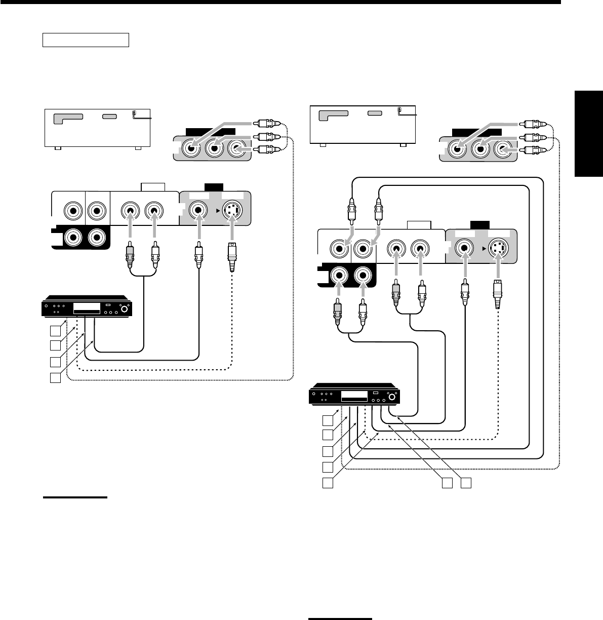
15
Français
• Lors de la connexion d’un lecteur DVD muni de prises de
sortie analogique discrète (reproduction 5,1 canaux):
Pour écouter le son après la connexion, appuyez sur DVD MULTI.
ÅÀ la sortie en composantes vidéo
ıÀ la sortie du caisson de grave
ÇÀ la sortie audio du canal central
ÎÀ la sortie S-Vidéo
‰À la sortie vidéo composite
ÏÀ la sortie audio du canal avant gauche/droit
ÌÀ la sortie audio du canal Surround gauche/droit
Remarque:
Lors de la connexion d’un lecteur de DVD aux prises d’entrée en
composantes vidéo, régler correctement l’entrée en composantes
vidéo. Référez-vous à la page 30 pour les détails.
Lecteur de DVD
• Lors de la connexion d’un lecteur DVD muni des prises de
sortie stéréo:
Pour écouter le son après la connexion, appuyez sur DVD.
ÅÀ la sortie en composantes vidéo
ıÀ la sortie S-Vidéo
ÇÀ la sortie vidéo composite
ÎÀ la sortie audio du canal avant gauche/droit (ou à la
sortie audio mixée, si nécessaire)
Remarque:
Lors de la connexion d’un lecteur de DVD aux prises d’entrée en
composantes vidéo, régler correctement l’entrée en composantes
vidéo pour AV COMPU LINK. Référez-vous à la page 30 pour les
détails.
Lecteur de DVD
Lecteur de DVD
DVD
VIDEO
RIGHT LEFT
S-VIDEO
VIDEO
AUDIO
SUBWOOFER CENTER
DVD
IN
FRONT
DVD
IN
COMPONENT VIDEO
DVD
IN
SURR
(REAR)
RL
A
B
C
D
RX-8030VBK/RX-7030VBK
DVD
VIDEO
RIGHT LEFT
S-VIDEO
VIDEO
AUDIO
SUBWOOFER CENTER
DVD
IN
FRONT
DVD
IN
COMPONENT VIDEO
DVD
IN
SURR
(REAR)
RL
RL
A
B
C
D
E F G
RX-8030VBK/RX-7030VBK
FR01-16_8030&7030[C]f.pm6 03.2.12, 6:01 PM15
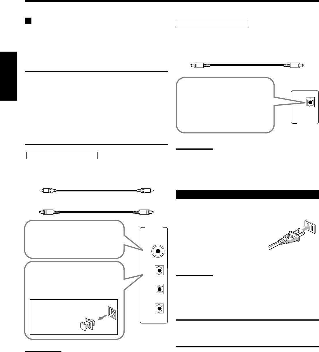
16
Français
DIGITAL IN
DIGITAL 1 (DVD)
DIGITAL 2 (CD)
DIGITAL 3 (TV)
DIGITAL 4 (CDR)
PCM/ DOLBY DIGITAL
/ DTS
DIGITAL OUT
Connexions numériques
Cet ampli-tuner est muni de quatre prises DIGITAL IN—une prise
coaxiale numérique et trois prises optiques numérique—et d’une
prise DIGITAL OUT (optique) sur le panneau arrière.
•Pour le RX-8030VBK: Une autre prise d’entrée optique
numérique est située sur le panneau avant (voir page 13).
IMPORTANT:
•Lors de la connexion d’un lecteur de DVD, d’un tuner de télévision
numérique ou d’un tuner DBS en utilisant les prises numériques,
vous devez aussi connecter la prise vidéo à l’arrière de l’ampli-tuner.
Sans cette connexion, vous ne pouvez pas voir l’image de lecture.
•Après avoir connecté les appareils vidéo en utilisant les prises
DIGITAL IN, effectuez, si nécessaire, les réglages suivants.
–Réglez la prise d’entrée numérique (DIGITAL IN) correctement.
Pour les détails, référez-vous à “Réglage des prises d’entrée
numériques” à la page 29.
–Choisissez le mode d’entrée numérique correctement. Pour les
détails, référez-vous à “Sélection du mode d’entrée analogique ou
numérique” à la page 19.
Remarques:
•A l’expédition de l’usine, les prises DIGITAL IN ont été réglées pour
être utilisées avec les appareils suivants:
–DIGITAL 1 (coaxial): Pour le lecteur de DVD
–DIGITAL 2 (optique): Pour le lecteur CD
–DIGITAL 3 (optique): Pour le tuner de télévision numérique
–DIGITAL 4 (optique): Pour l’enregistreur de CD
•Si vous souhaitez commander le lecteur CD ou l’enregistreur de
CD (ou l’enregistreur de MD: uniquement pour le RX-8030VBK) en
utilisant le système de commande à distance COMPU LINK,
connectez aussi l’appareil en question comme décrit dans
“Connexions analogiques” (voir pages 12 et 13).
•Si vous souhaitez commander le lecteur DVD en utilisant le
système de commande à distance AV COMPU LINK (voir page 42),
connectez aussi le lecteur de DVD comme décrit dans “Connexions
analogiques”(voir page 15).
Prises d’entrée numériques
Vous pouvez connecter n’importe quel appareil numérique
possédant une prise de sortie numérique coaxiale ou optique.
Prise de sortie numérique
Vous pouvez connecter n’importe quel appareil numérique muni
d’une prise d’entrée numérique optique.
Câble coaxial numérique (non fourni)
entre les prises numériques coaxiales
Câble optique numérique (non fourni)
entre les prises numériques optiques
Avant de connecter un câble
numérique optique, enlever
le capuchon
protecteur.
Quand l’appareil a une prise de sortie
numérique optique, connectez-la à la
prise DIGITAL 2 (CD), DIGITAL 3 (TV)
ou DIGITAL 4 (CDR) en utilisant un
câble numérique optique (non fourni).
Quand l’appareil a une prise de sortie
numérique coaxiale, connectez-la à la
prise DIGITAL 1 (DVD), en utilisant un
câble numérique coaxial (non fourni).
Quand l’appareil d’enregistrement
numérique, tel qu’un enregistreur
de MD et un enregistreur de CD
possède une prise d’entrée optique
numérique, connectez-la à la prise
DIGITAL OUT permet d’effectuer
un enregistrement numérique-
numérique.
Câble optique numérique (non fourni)
entre les prises numériques optiques
Remarque:
Le format du signal numérique sorti par la prise DIGITAL OUT est le
même que celui du signal d’entrée. Cela signifie que quand des
signaux DTS Digital Surround sont entrés, les mêmes signaux DTS
Digital Surround sont sortis.
Connexion du cordon d’alimentation secteur
Avant de brancher l’ampli-tuner sur une prise d’alimentation
secteur, assurez-vous que toutes les connexions ont été faites.
Branchez le cordon d’alimentation sur
une prise secteur murale.
Tenez le cordon d’alimentation à l’écart
des câbles de connexion et d’antenne. Le cordon d’alimentation
risquerait de causer des bruits ou des interférences sur l’écran.
Remarque:
Les réglages préréglés tels que les canaux préréglés et les
ajustements sonores peuvent être effacés au bout de quelques jours
dans les cas suivants:
–Quand le cordon d’alimentation est débranché.
–Quand une coupure de courant se produit.
ATTENTIONS:
•Ne touches pas le cordon d’alimentation avec les mains mouillées.
•Ne tirez pas sur le cordon d’alimentation pour débrancher la fiche.
Saisissez toujours directement la fiche de façon à ne pas
endommager le cordon.
FR01-16_8030&7030[C]f.pm6 03.2.12, 6:01 PM16
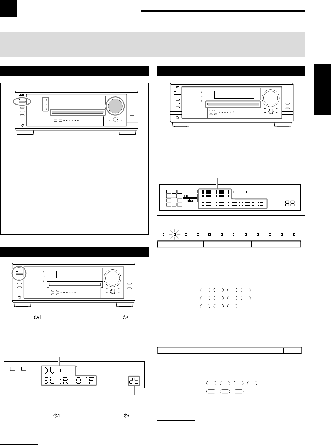
17
Français
Opérations de base
Les opérations suivantes sont utilisées ordinairement lors de la reproduction de n’importe quelle source.
Les opérations ci-après sont expliquées en utilisant les touches du panneau avant.
Vous pouvez aussi utiliser les touches de la télécommande pour la même fonction si elles portent le même nom/marque ou un nom/
marque similaire.
Sélection de la source de lecture
Appuyez sur une des touches de sélection de source.
•Le nom de la source choisie et le mode Surround/DSP
précédemment choisi apparaissent sur l’affichage.
Le nom de la source choisie et mode
Surround/DSP actuel apparaissent.
Pour le RX-8030VBK
•Le témoin de la source choisie s’allume (ex. quand DVD est choisi
comme source).
Pour le RX-7030VBK
Remarques:
•For RX-8030VBK: Lors de la connexion d’un enregistreur de MD
(aux prises TAPE/MD) et d’un tuner DBS (aux prises TV SOUND/
DBS), changez le nom de la source qui apparaît sur l’affichage.
Référez-vous à la page 21 pour les détails.
•For RX-7030VBK: Lors de la connexion d’un enregistreur de CD
(aux prises TAPE/CDR) et d’un tuner DBS (aux prises TV SOUND/
DBS), changez le nom de la source qui apparaît sur l’affichage.
Référez-vous à la page 21 pour les détails.
Utilisation de base quotidienne
1Mettez l’appareil sous tension.
•Référez-vous à “Mise sous tension de l’appareil” ci-dessous.
2Choisissez la source.
•Référez-vous à “Sélection de la source de lecture” ci-à
droite.
3Ajustez le volume.
•Référez-vous à “Ajustement du volume” à la page 18.
4Choisissez le mode Surround ou DSP.
•Référez-vous à “Mise en service du mode Surround”
(page 37) et “Mise en service du mode DSP” (page 39).
Mise sous tension de l’appareil
Appuyez sur STANDBY/ON (ou sur AUDIO sur la
télécommande).
Le témoin STANDBY s’éteint. Le nom de la source actuelle et le
mode Surround/DSP apparaissent sur l’affichage.
Le nom de la source actuelle et le mode
Surround/DSP apparaissent
Le niveau de volume actuel apparaît
Pour mettre l’appareil hors tension (en mode d’attente),
appuyez de nouveau sur STANDBY/ON (ou AUDIO sur la
télécommande).
Le témoin STANDBY s’allume.
Remarque:
Une petite quantité de courant est consommée ne mode d’attente.
Pour mettre l’appareil complètement hors tension, débranchez le
cordon d’alimentation secteur.
Sur l’appareil
Sur la télécommande
Sur l’appareil
Sur la télécommande
DVD MULTI CD
CDR TAPE/MD
TV/DBS VIDEO PHONO
FM/AM
VCR1 VCR2
DVD
DVD MULTI CD
TAPE/CDR
FM/AM
TV/DBS VCR
DVD
TV SOUND/DBSVCR
DVDDVD MULTI AMFMTAPE/CDRCD
13
2
4
VOLUME
LINEAR PCM
LR
ANALOG
SPEAKERS 1
DIGITAL EQ
INPUT ATT
SLEEP
VOLUME
ONE TOUCH OPERATION
3D - PHONIC
NEO:6 VIRTUAL SB MIDNIGHT MODE
AUTO MUTING
TUNED STEREO
LINEAR PCM
DIGITAL
L
SUBWFR
LS RS
CR
S
LFE
DUAL DIGITAL AUTO
ANALOG 96/24 MULTI
PRO LOGIC
DSP
HEADPHONE SPEAKERS 1 2 BASS BOOST
SB
TV SOUND
/DBS
VIDEOVCR 2VCR 1
DVDDVD MULTI AMFMTAPE/MDCDRCDPHONO
FR17-22_8030&7030[C]f.pm6 03.2.12, 6:01 PM17
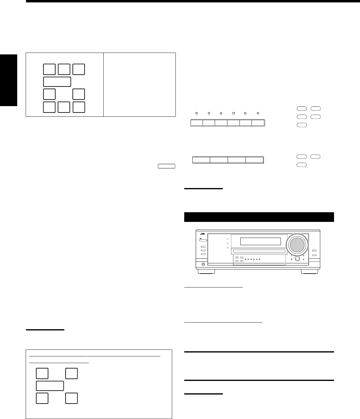
18
Français
Indicateurs d’enceinte et de signal sur l’affichage
En vérifiant les indicateurs suivants, vous pouvez vérifier facilement
quelle enceinte est en service et quels signaux entrent dans cet
ampli-tuner.
Quel indicateur s’allume dépend du réglage des enceintes (pour
les détails, référez-vous à “Réglage des enceintes” à la page 27).
•Les cadres de “L”, “C”, “R”, “LS”, “RS”, et “SB” s’allument,
quand les enceintes correspondantes sont réglées sur “LARGE” ou
“SMALL” et que l’enceinte est requise pour le mode Surround/
DSP actuellement sélectionné.
•Quand “SUB WOOFER” est réglé sur “YES” l’indicateur SUBWFR
s’allume (voir page 27).
•Les trois cadres de la ligne “SB” ne sont pas utilisés en même
temps. Quand “SBACK OUT” est réglé sur “2SPK”, les cadres
gauche et droit sont utilisés. Quand il est réglé sur “1SPK”, le
cadre du milieu est utilisé (voir page 27).
Les indicateurs de signal s’allument pour indiquer les signaux
entrants.
L:•Quand l’entrée numérique est choisie: S’allume lors de
l’entrée du signal du canal gauche.
•Quand l’entrée analogique est choisie: Toujours allumé.
R:•Quand l’entrée numérique est choisie: S’allume lors de
l’entrée du signal du canal droite.
•Quand l’entrée analogique est choisie: Toujours allumé.
C:S’allume lors de l’entrée du signal du canal central.
LFE:S’allume lors de l’entrée du signal du canal LFE.
LS:S’allume lors de l’entrée du signal du canal Surround gauche.
RS:S’allume lors de l’entrée du signal du canal Surround droit.
S:S’allume lors de l’entrée d’un signal de canal Surround
monaural.
SB:S’allume lors de l’entrée d’un signal de canal Surround
arrière.
Remarque:
Quand “DVD MULTI” est choisi comme source, “L”, “C”, “R”, “LFE”,
“LS” et “RS” s’allument.
Indicateurs de signalIndicateurs d’enceinte
Sur l’appareil Sur la télécommande
CD
CDR TAPE/MD
PHONO
FM/AM
AMFMTAPE/CDRCD
CD
TAPE/CDR
FM/AM
Ajustement du volume
Sur le panneau avant:
Pour augmenter le volume, tournez MASTER VOLUME dans le
sens des aiguilles d’une montre.
Pour diminuer le volume, tournez-le dans le sens contraire.
A partir de la télécommande:
Pour augmenter le volume, appuyez sur VOLUME +.
Pour diminuer le volume, appuyez sur VOLUME –.
ATTENTION:
Réglez toujours le volume au minimum avant de démarrer une
source. Si le volume est réglé sur un niveau élevé, la soudaine
déflagration d’énergie sonore peut endommager de façon irréversible
votre ouïe et/ou détruire les enceintes.
Remarques:
•Le niveau de volume peut être ajusté à l’intérieur d’une plage de
“0” (minimum) à “70” (maximum).
•Si le fonctionnement monotouche est en service (“ON”) (voir page
30), il n’est pas nécessaire d’ajuster le niveau de volume chaque
fois que la source est changée. Il est réglé automatiquement au
niveau mémorisé.
Sélection d’une source différente pour l’image
et le son
Quand vous regardez des images provenant d’une source vidéo,
vous pouvez écouter le son d’une source audio.
•Une fois que vous avez choisi une source vidéo, les images de la
source choisie sont transmises au téléviseur jusqu’à ce que vous
choisissiez une autre source vidéo.
Appuyez sur une des touches de sélection de source audio
pendant que vous regardez l’image d’un appareil vidéo tel que
le magnétoscope, le lecteur de DVD, etc.
Pour le RX-8030VBK
Pour le RX-7030VBK
Remarque:
Quand vous regardez les images par les prises COMPONENT
VIDEO, vous ne pouvez pas utiliser cette fonction.
AMFMTAPE/MDCDRCDPHONO
LFE
SUBWFR
LCR
LS RS
SB
Ex. Aucun son ne sort de
l’enceinte centrale et des
enceintes Surround arrière
bien que des signaux du
canal central et du canal
Surround arrière entrent dans
cet ampli-tuner.
Comment comprendre l’éclairage des indicateurs
d’enceinte et de signal
Sur l’appareil Sur la télécommande
SUBWFR
LCR
LS RS
LFE
LCR
SLS
SB
RS
SB
FR17-22_8030&7030[C]f.pm6 03.2.12, 6:01 PM18
19
Français
Mise en service et ajustement
du son du caisson de grave
Vous pouvez annuler le son du caisson de grave même si vous avez
connecté un caisson de grave et réglé “SUB WOOFER” sur “YES”
(voir page 27). C’est très pratique si vous souhaitez écouter de la
musique la nuit.
Appuyez sur SUBWOOFER OUT ON/OFF pour annuler la
sortie du son du caisson de grave.
Chaque fois que vous appuyez sur la touche, la sortie du son du
caisson de grave est mise alternativement hors service (“SUBWFR
OFF”) et en service (“SUBWFR ON”).
•Quand la sortie du son du caisson de grave est en service, le
niveau de sortie du caisson de grave peut être ajusté en utilisant la
télécommande.
1 Appuyez sur SOUND.
2 Appuyez sur SUBWOOFER.
3 Appuyez sur LEVEL + ou – pour ajuster le niveau de sortie
(–10 dB à +10 dB).
Remarques:
Vous ne pouvez pas mettre hors service la sortie du son du caisson
de grave quand vous avez réglé “SMALL” pour les enceintes avant
dans le réglage de la taille des enceintes (voir page 27) ou la
configuration rapide des enceintes.
Écoute privée avec un casque d’écoute:
Mettez hors service les deux jeux d’enceintes avant et connectez un
casque d’écoute à la prise PHONES.
Vous pouvez profiter les effets sonores à travers le casque d’écoute
quand le mode Surround ou DSP est en service—mode 3D
HEADPHONE (3D H PHONE).
•“3D H PHONE” apparaît sur l’affichage et l’indicateur DSP et
HEADPHONE s’allume sur l’affichage. (Pour les détails, référez-
vous à la page 36.)
Remarque:
Quand vous choisissez “DVD MULTI” comme source ou un mode
Surrond/DSP qui met en service l’enceinte centrale et/ou les
enceintes Surround, vous pouvez utiliser uniquement un jeu
d’enceintes.
ATTENTION:
Assurez-vous de réduire le volume:
•Avant de connecter le casque d’écoute ou de vous le mettre sur les
oreilles, car un volume élevé peut endommager à la fois le casque
et vos oreilles.
•Avant de remettre les enceintes en services, car un volume élevé
peut être sorti par les enceintes.
Sélection des enceintes avant
Si vous avez connecté deux paires d’enceintes avant, vous pouvez
choisir laquelle utiliser.
Pour utiliser les enceintes connectées aux prises FRONT
SPEAKERS 1, appuyez sur SPEAKERS ON/OFF 1 de façon que
l’indicateur SPEAKERS 1 s’allume sur l’affichage. Assurez-vous
que l’indicateur SPEAKERS 2 n’est pas allumé sur l’affichage.
Pour utiliser les enceintes connectées aux prises FRONT
SPEAKERS 2, appuyez sur SPEAKERS ON/OFF 2 de façon que
l’indicateur SPEAKERS 2 s’allume sur l’affichage. Assurez-vous
que l’indicateur SPEAKERS 1 n’est pas allumé sur l’affichage.
Pour utiliser les deux jeux d’enceintes, appuyez sur SPEAKERS
ON/OFF 1 et SPEAKERS ON/OFF 2 de façon que les indicateurs
SPEAKERS 1/2 s’allument sur l’affichage.
Pour n’utiliser aucun jeu d’enceintes, appuyez sur SPEAKERS
ON/OFF 1 et SPEAKERS ON/OFF 2 de façon que les indicateurs
SPEAKERS 1/2 disparaissent de l’affichage.
L’indicateur HEADPHONE s’allume et “HEADPHONE” apparaît
sur l’affichage.
•Mettre les enceintes en service, met aussi en service les modes
Surround et DSP choisis précédemment.
Sélection du mode d’entrée analogique ou
numérique
Si vous avez connecté des appareils source numériques en utilisant
les prises numériques (voir page 16), changez le mode d’entrée pour
ces appareils sur le mode d’entrée numérique.
Avant de commencer, rappelez-vous...
Le réglage de la prise d’entrée numérique doit être fait
correctement pour les sources pour lesquelles vous voulez
choisir le mode d’entrée numérique (référez-vous à “Réglage des
prises d’entrée numériques” aux pages 29 et 30).
1. Appuyez sur la touche de sélection de la source pour
laquelle vous souhaitez changer le mode d’entrée.
•Pour le RX-8030VBK: DVD, VIDEO, TV (SOUND)/
DBS, CD, CDR ou TAPE/MD*
•Pour le RX-7030VBK: DVD, TV (SOUND)/DBS, CD ou
TAPE/CDR*
*
Si “TAPE” est choisi comme source, le mode d’entrée numérique
n’est pas disponible. polur changer le nom de la source, référez-
vous à “Modification du nom de la source” à la page 21.
Suite à la page suivante
Remote
NOT
Remote
NOT
FR17-22_8030&7030[C]f.pm6 03.2.12, 6:01 PM19
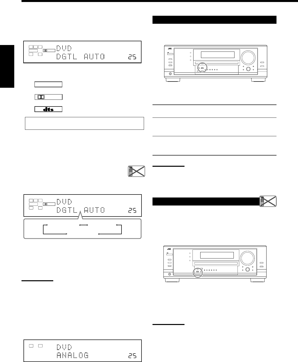
20
Français
LINEAR PCM
DIGITAL
Lors de la reproduction d’une source codée avec Dolby Digital
ou DTS, les symptômes suivant peuvent se produire:
•Aucun son ne sort au début de la lecture.
•Il y a du bruit lors de la recherche ou du saut de chapitres ou de
plages.
Dans ce cas, appuyez répétitivement sur INPUT
DIGITAL pour choisir “DGTL D.D” ou “DGTL DTS”
pendant que “DGTL AUTO” apparaît sur l’affichage.
•Quand vous appuyez sur la touche INPUT DIGITAL, le mode
d’entrée change comme suit:
Quand “DGTL D.D” ou “DGTL DTS” est choisi, l’indicateur
AUTO s’éteint et l’indicateur de format de signal numérique
correspondant s’allume sur l’affichage.
•Si le signal entrant ne correspondant pas au format de signal
numérique, le cadre de l’indicateur choisi clignote.
Remarque:
Quand vous mettez l’appareil hors tension ou que vous choisissez
une autre source, les réglages “DGTL D.D” et “DGTL DTS” sont
annulés et le mode d’entrée numérique est réinitialisé
automatiquement sur “DGTL AUTO”.
Pour choisir de nouveau le mode d’entrée analogique
Appuyez INPUT ANALOG (ou appuyez répétitivement sur
ANALOG/DIGITAL INPUT sur la télécommande jusqu’à ce que
“ANALOG” apparaisse sur l’affichage). L’indicateur ANALOG
s’allume.
2. Appuyez sur INPUT DIGITAL (ou ANALOG/
DIGITAL INPUT sur la télécommande) pour choisir
“DGTL AUTO”.
L’indicateur DIGITAL AUTO s’allume sur l’affichage.
•Quand “DGTL AUTO” est choisi, les indicateurs suivants
indiquent le format du signal numérique du signal entrant.
:S’allume lors de l’entrée des signaux
Linear PCM.
:S’allume lors d’entrée d’un signal Dolby
Digital.
:S’allume lors de l’entrée d’un signal DTS.
Aucun indicateur n’est allumé quand l’ampli-tuner ne peut pas
reconnaître le format du signal numérique entrant.
VOLUME
DIGITAL
L
SUBWFR
LS RS
CR
LFE
DIGITAL AUTO
SPEAKERS 1
DGTL AUTO DGTL D.D
DGTL DTS
(Dolby Digital)
(Digital)
VOLUME
LINEAR PCM
LR
ANALOG
SPEAKERS 1
VOLUME
DIGITAL
L
SUBWFR
LS RS
CR
LFE
DIGITAL AUTO
SPEAKERS 1
Réglage de la plage dynamique
Vous pouvez profiter d’un son puissant la nuit en utilisant le mode
de minuit (Midnight).
Appuyez sur MIDNIGHT MODE de façon que “MID NIGHT
1” ou “MID NIGHT 2” apparaisse sur l’affichage.
L’indicateur MIDNIGHT MODE s’allume aussi.
MID NIGHT 1: Choisissez ce réglage quand vous souhaitez
réduire légèrement la plage dynamique.
MID NIGHT 2: Choisissez ce réglage quand vous souhaitez
appliquer entièrement l’effet de compression
(pratique la nuit).
MID NIGHT OFF: Choisissez ce réglage quand vous souhaitez
profiter du Surround avec sa plage dynamique
complète (aucun effet n’est appliqué).
Remarques:
•Si la fonction Analog Direct est en service le mode de minuit est
annulé temporairement.
•Le mode de minuit ne fonctionne pas pour le mode de lecture DVD
MULTI.
Atténuation du signal d’entrée
Quand le niveau d’entrée de la source analogique est trop élevé, les
sons sont déformés. Si cela se produit, vous devez atténuer le niveau
du signal d’entrée pour éviter la distorsion du son.
•Une fois que vous avez fait l’ajustement, il est mémorisé pour
chaque source analogique.
Maintenez pressée INPUT ATT (INPUT ANALOG) de façon
que l’indicateur INPUT ATT s’allume sur l’affichage.
•Chaque fois que vous maintenez pressée la touche, le mode
d’atténuation du signal d’entrée se met en service (“ATT ON”) ou
hors service (“NORMAL”).
Remarque:
Cette fonction n’est pas valide quand “DVD MULTI” est choisi ou
quand la fonction Analog Direct est en service.
Remote
NOT
Remote
NOT
FR17-22_8030&7030[C]f.pm6 03.2.12, 6:01 PM20
21
Français
Mise en et hors service de la fonction
Analog Direct
Vous pouvez reproduire un son proche de la source originale en
outrepassant les ajustements sonores tels que les ajustements du
niveau de sortie des enceintes (voir page 32), l’égalisation
numérique (voir page 32), les modes Surround et DSP (voir pages
34 à 39), l’accentuation des graves (voir page 22) et le mode de
minuit (voir page 20). Vous pouvez uniquement ajuster le niveau de
volume quand la fonction Analog Direct est en service.
•Une fois que vous avez réalisé l’ajustement, il est mémorisé pour
chaque source analogique.
Appuyez sur ANALOG DIRECT de façon que “A DIRECT”
apparaisse sur l’affichage.
Le témoin sur la touche s’allume aussi.
•Chaque fois que vous appuyez sur la touche, la fonction Analog
Direct se met en et hors service.
Remarques:
•Quand le mode d’entrée numérique et utilisé, la fonction Analog
Direct n’est pas disponible.
•Mettre en service le mode Surround ou DSP annule la fonction
Analog Direct et les ajustements sonores précédemment choisis
sont rappelés.
•Si la fonction Analog Direct est utilisée, le mode de minuit est
annulé temporairement.
•La mise en service de la fonction Analog Direct annule l’atténuation
de l’entrée (page 20) (et le convertisseur CC pour le RX-8030VBK:
ci-dessous).
Reproduction de sons naturels
Le convertisseur CC (Compression Compensatrice) de JVC élimine le
bouger et les bandes, permettant une réduction importante des
distorsions numériques par un traitement des données numériques
musicales par quantification 24 bits et expansion de la fréquence
d’échantillonnage à 128 kHz (pour les signaux fs 32 kHz)/176,4 kHz
(pour les signaux fs 44,1 kHz)/192 kHz (pour les signaux fs 48 kHz).
En utilisant le convertisseur CC, vous pourrez obtenir un champ
sonore naturel avec des sources digitales et des sources analogiques.
Appuyez sur CC CONVERTER de façon que le témoin sur la
touche s’allume.
•Chaque fois que vous appuyez sur la touche, le convertisseur CC
ne met alternativement en et hors service (le témoin s’éteint).
Remarque:
Vous ne pouvez pas utiliser cette fonction quand Analog Direct est en
service. Si vous mettez en marche Analog Direct pendant que cette
fonction est en service, cette fonction sera annulée.
Modification du nom de la source
Si un enregistreur de MD a été connecté aux prises TAPE/MD ou si un
tuner DBS a été connecté aux prises TV SOUND/DBS sur le panneau
arrière, changez le nom de source qui apparaît sur l’affichage.
Pour changer le nom de source de “TV” sur “DBS”:
1. Appuyer sur TV SOUND/DBS.
•S’assurer que “TV” apparaît sur l’affichage.
2. Maintenir pressée TV SOUND/DBS jusqu’à ce que “ASSGN
DBS” apparaisse sur l’affichage.
Remarque:
Si vous connectez un tuner DBS aux prises TV SOUND/DBS IN,
changez le nom de la source sur “DBS”, qui apparaîtra sur l’affichage
quand la source est choisie. Sinon, vous ne pouvez pas voir l’image
du tuner DBS.
Pour le RX-8030VBK:
Pour changer le nom de source de “TAPE” sur “MD”:
1. Appuyer sur TAPE/MD.
•S’assurer que “TAPE” apparaît sur l’affichage.
2. Maintenir pressée TAPE/MD jusqu’à ce que “ASSGN MD”
apparaisse sur l’affichage.
Pour le RX-7030VBK:
Pour changer le nom de source de “TAPE” sur “CDR”:
1. Appuyer sur TAPE/CDR.
•S’assurer que “TAPE” apparaît sur l’affichage.
2. Maintenir pressée TAPE/CDR jusqu’à ce que “ASSGN
CDR” apparaisse sur l’affichage.
Pour changer le nom de la source sur “TV” et “TAPE”, répétez
la procédure ci-dessus.
Remarque:
Sans changer le nom de source, vous pouvez quand même utiliser les
appareils connectés. Cependant, il peut y avoir quelques inconvénients.
•Pour le RX-8030VBK:
–“TAPE” ou “TV” apparaît sur l’affichage quand vous choisissez
l’enregistreur de MD ou le tuner DBS.
–Vous ne pouvez pas utiliser l’entrée numérique (voir pages 19 et
20) pour l’enregistreur de MD.
–Vous ne pouvez pas utiliser le système de commande à distance
COMPU LINK (voir page 41) pour commander l’enregistreur de MD.
•Pour le RX-7030VBK:
–“TAPE” ou “TV” apparaît sur l’affichage quand vous choisissez
l’enregistreur de CD ou le tuner DBS.
–Vous ne pouvez pas utiliser l’entrée numérique (voir pages 19 et
20) pour l’enregistreur de CD.
VOLUME
LINEAR PCM
LR
ANALOG
SPEAKERS 1
RX-8030V
ONLY
Remote
NOT
FR17-22_8030&7030[C]f.pm6 03.2.12, 6:01 PM21
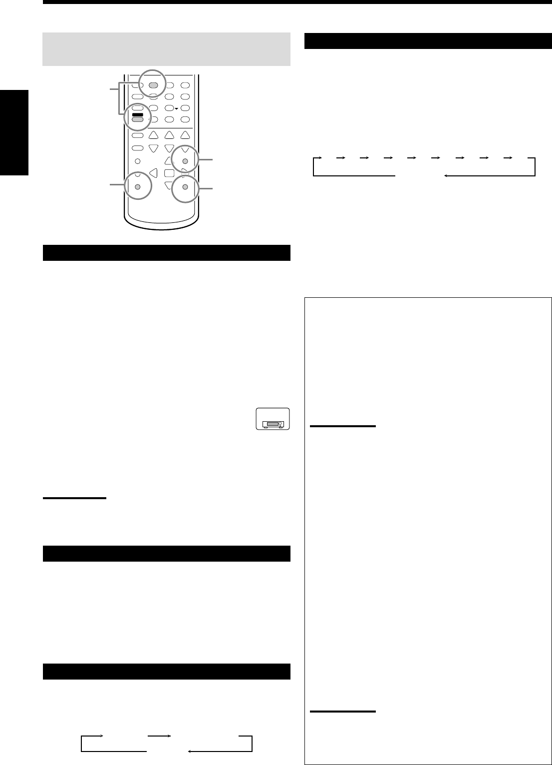
22
Français
Les opérations de base suivantes sont possibles uniquement
en utilisant la télécommande.
Accentuation des graves
Vous pouvez accentuer le niveau des graves.
•Une fois que l’ajustement est réalisé, il est mémorisé pour chaque
source.
1. Appuyez sur SOUND.
Les touches numériques sont mises en service pour les
ajustements sonores.
2. Appuyez sur BASS BOOST pour mettre l’accentuation des
graves en service.
L’indicateur BASS BOOST s’allume.
•Chaque fois que vous appuyez sur la touche, la fonction
d’accentuation des graves est mise alternativement en service
(“BOOST ON”) et hors service (“BOOST OFF”).
Pour le RX-7030VBK:
Vous pouvez utiliser la touche BASS BOOST sur le
panneau avant.
Quand la fonction d’accentuation des graves est en service, le
témoin sur la touche s’allume.
•Chaque fois que vous appuyez sur la touche, l’accentuation des
graves est mise en et hors service.
Remarques:
•Cette fonction affecte uniquement le son des enceintes avant, de
l’enceinte centrale et du caisson de grave.
•Quand Analog Direct est en service (voir page 21), l’accentuation
des graves est annulée temporairement.
Mise en sourdine du son
Appuyez sur MUTING pour couper le son de toutes les enceintes
et du casque d’écoute connecté.
“MUTING” apparaît sur l’affichage et le son est coupé (l’indicateur
du niveau de VOLUME s’éteint).
Pour rétablir le son, appuyez de nouveau sur MUTING.
•Tourner MASTER VOLUME sur le panneau avant ou appuyer sur
VOLUME +/– sur la télécommande rétablit aussi le son.
Modification de la luminosité de l’affichage
Vous pouvez réduire la luminosité de l’affichage.
Appuyez sur DIMMER.
•Chaque fois que vous appuyez sur la touche, le niveau de
luminosité de l’affichage change comme suit:
Enregistrement d’une source
Pour l’enregistrement analogique-analogique
Vous pouvez enregistrer n’importe quelle source analogique, en
même temps, sur tous les appareils d’enregistrement connectés
aux prises audio à l’arrière de l’appareil.
Pour l’enregistrement numérique-numérique
Vous pouvez enregistrer l’entrée numérique choisie actuellement
à travers l’ampli-tuner sur l’appareil d’enregistrement numérique
connecté à la prise DIGITAL OUT.
Remarques:
•Les enregistrements analogique-numérique et numérique-
analogique ne sont pas possibles.
•Le niveau du volume de sortie, le mode de minuit (voir page 20),
l’accentuation des graves (voir la colonne de gauche),
l’égalisation numérique (voir page 32), les modes Surround et
les modes DSP (voir pages 34 à 39) n’affectent pas
l’enregistrement.
Ajustement de base et mémorisation
automatique
Cet appareil mémorise les réglages sonores pour chaque
source—
•Quand vous mettez l’appareil hors tension.
•Quand vous changez la source.
•Quand vous affectez un nom à la source (voir page 21).
Quand vous changez la source, les réglages mémorisés pour la
nouvelle source choisie sont rappelés automatiquement.
Les réglages suivants peuvent être mémorisés pour chaque
source:
•Mode d’entrée analogique/numérique (voir pages 19 et 20)
•Mode d’atténuation de l’entrée (voir page 20)
•Le mode Analog Direct (voir page 21)
•Égalisation numérique (voir page 32)
•Niveaux de sortie des canaux d’enceinte (voir page 32)
•Sélection du mode Surround et DSP (voir pages 37 à 39)
•Réglage de l’accentuation des graves (voir la colonne de gauche)
Remarques
:
•Si la source est FM ou AM, vous pouvez mémoriser un réglage
différent pour chaque bande.
•Si vous souhaitez mémoriser le niveau de volume avec les
réglages ci-dessus, réglez le fonctionnement monotouche sur
“ON” (voir page 30).
Utilisation de la minuterie d’arrêt
En utilisant la minuterie d’arrêt, vous pouvez vous endormir tout en
écoutant de la musique.
Quand l’heure d’arrêt arrive, l’ampli-tuner se met automatiquement
hors tension.
Appuyez répétitivement sur SLEEP.
L’indicateur SLEEP s’allume sur l’affichage et
l’heure de mise hors tension change par intervalle
de 10 minutes:
Pour vérifier ou changer la durée restante avant la mise hors tension:
Appuyez une fois sur SLEEP.
La durée restante jusqu’à la mise hors tension apparaît en minutes.
•Pour changer la durée restante, appuyez répétitivement sur SLEEP.
Pour annuler la minuterie d’arrêt:
Appuyez répétitivement sur SLEEP jusqu’à ce que “SLEEP 0min”
apparaisse sur l’affichage. (L’indicateur SLEEP s’éteint.)
•Mettre l’appareil hors tension annule aussi la minuterie d’arrêt.
231
564
89
7/P
0+10
BOOST
BASS
MUTING
DIMMER
SLEEP
10/0
SOUND
Accentuation
des graves
Utilisation de la
minuterie
d’arrêt
Mise en
sourdine du son
Modification de
la luminosité
sur l’affichage
2010 30 40 50 60 70 80 90
(Annulé)
0
RX-7030V
ONLY
Assombri Très assombri
Annulé
(Affichage normal)
FR17-22_8030&7030[C]f.pm6 03.2.12, 6:01 PM22
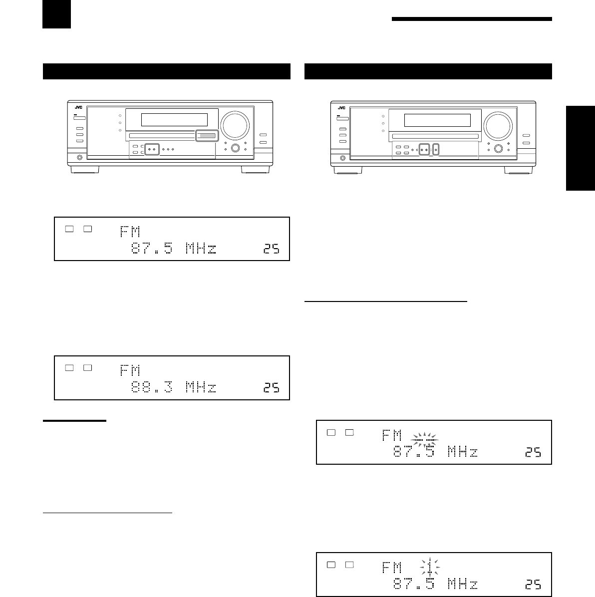
23
Français
Réception d’émissions de radio
Vous pouvez parcourir toutes les stations ou utiliser la fonction de préréglage pour aller directement à une station particulière.
Accord manuel d’une station
1. Appuyez sur FM ou AM pour choisir la bande.
La dernière station reçue de la dernière bande choisie est accordée.
2. Appuyez répétitivement sur FM/AM TUNING 5
ou ∞ jusqu’à ce que vous trouviez la fréquence
souhaitée.
•Appuyer sur FM/AM TUNING 5 augmente la fréquence.
•Appuyer sur FM/AM TUNING ∞ réduit la fréquence.
Remarques:
•Quand une station de signal suffisamment fort est accordée,
l’indicateur TUNED s’allume sur l’affichage.
•Quand un programme FM stéréo est reçu, l’indicateur STEREO
s’allume aussi.
•Quand vous maintenez la touche pressée puis la relâchez à l’étape
2
, la fréquence continue de changer jusqu’à ce qu’une station soit
accordée.
A partir de la télécommande:
1. Appuyez sur FM/AM.
•Chaque fois que vous appuyez sur la touche, la bande alterne
entre FM et AM.
2. Appuyez répétitivement sur TUNING UP ou TUNING
DOWN jusqu’à ce que vous trouviez la fréquence souhaitée.
•Appuyer sur TUNING UP augmente la fréquence.
•Appuyer sur TUNING DOWN réduit la fréquence.
VOLUME
TUNED STEREO
LINEAR PCM
LR
ANALOG
SPEAKERS 1
VOLUME
TUNED STEREO
LINEAR PCM
LR
ANALOG
SPEAKERS 1
VOLUME
TUNED STEREO
LINEAR PCM
LR
ANALOG
SPEAKERS 1
VOLUME
TUNED STEREO
LINEAR PCM
LR
ANALOG
SPEAKERS 1
Utilisation de l’accord par préréglage
Une fois qu’une station est affectée à un numéro de canal, cette
station peut être accordée rapidement. Vous pouvez prérégler un
maximum de 30 stations FM et de 15 stations AM.
Pour mémoriser les stations préréglées
Avant de commencer, rappelez-vous...
Il y a un temps limite pour réaliser les étapes suivantes. Si le réglage
est annulé avant la fin, recommencez à partir de l’étape 2.
Sur le panneau avant UNIQUEMENT:
1. Accorder la station que vous souhaitez prérégler
(référez-vous à “Accord manuel d’une station” ci-à
gauche).
•Si vous souhaitez mémoriser le mode de réception FM pour
cette station, choisissez le mode de réception FM souhaité.
Référez-vous à “Sélection du mode de réception FM” à la
page 24.
2. Appuyez sur MEMORY.
La position de numéro de canal clignote sur l’affichage pendant
environ 10 secondes.
3. Appuyez sur FM/AM PRESET 5 ou ∞ pour
choisir un numéro de canal pendant que la
position du numéro de canal clignote.
4. Appuyez de nouveau sur MEMORY pendant que
le numéro du canal choisi clignote sur l’affichage.
Le numéro du canal choisi s’arrête de clignoter.
La station est affectée au numéro de canal choisi.
5. Répétez les étapes 1 à 4 pour mémoriser les
autres stations.
Pour effacer une station préréglée
Enregistrer une nouvelle station sur un numéro utilisé, efface la
station précédente.
FR23-24_8030&7030[C]f.pm6 03.2.12, 6:01 PM23
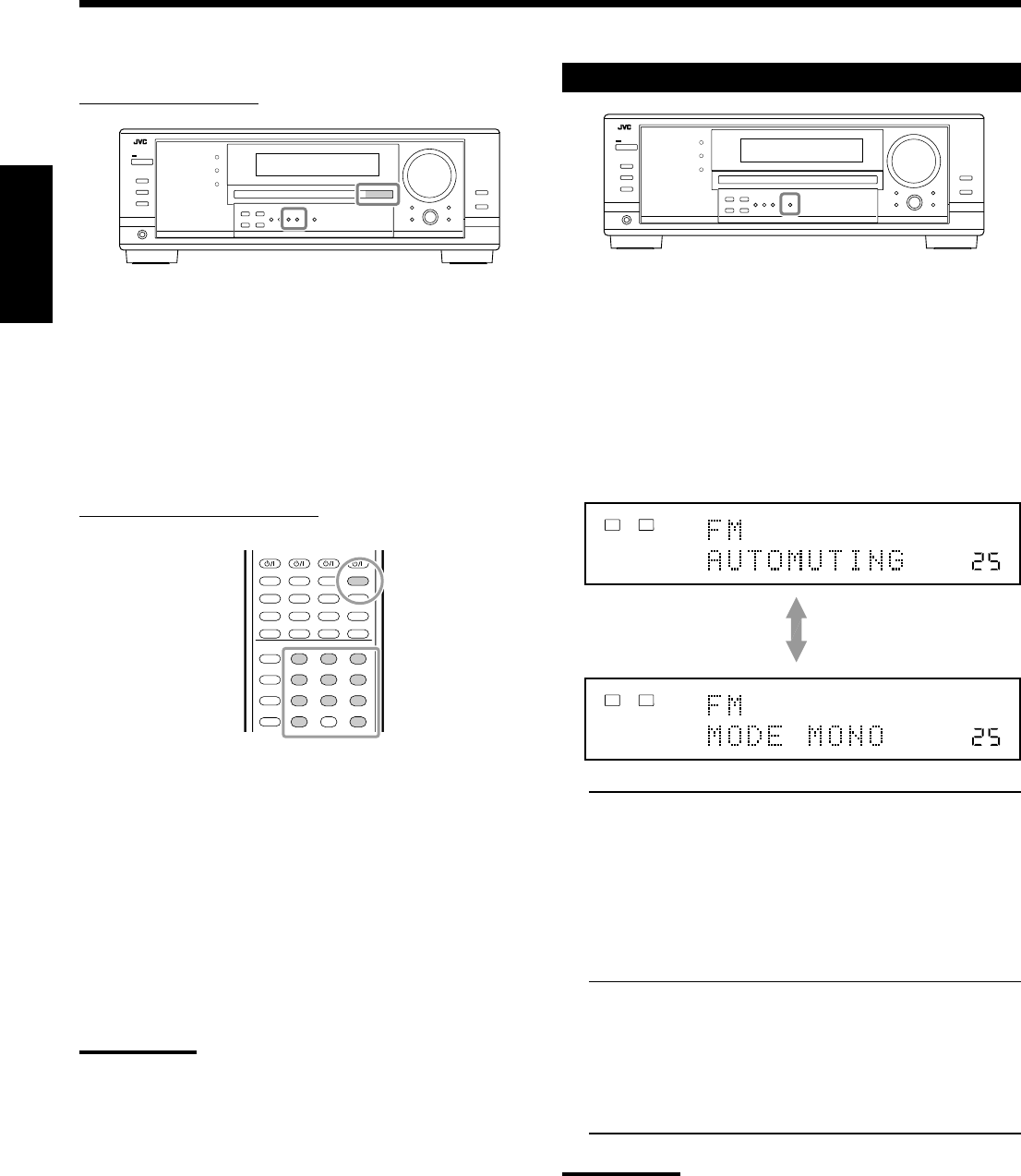
24
Français
Pour accorder une station préréglée
Sur le panneau avant:
1. Appuyez sur FM ou AM pour choisir la bande.
La dernière station reçue de la dernière bande choisie est accordée.
2. Appuyez répétitivement sur FM/AM PRESET 5
ou ∞ jusqu’à ce que vous trouviez le canal
souhaité.
•Appuyez sur FM/AM PRESET 5 augmente le numéro.
•Appuyez sur FM/AM PRESET ∞ diminue le numéro.
A partir de la télécommande:
1. Appuyez sur FM/AM pour choisir la bande.
La dernière station reçue de la dernière bande choisie est accordée.
•Chaque fois que vous appuyez sur la touche, la bande alterne
entre FM et AM.
2. Appuyez sur les touches numériques pour choisir
un numéro de canal préréglé.
•Pour le numéro 5, appuyez sur 5.
•Pour le numéro 15, appuyez sur +10 puis sur 5.
•Pour le numéro 20, appuyez sur +10 puis sur 10.
•Pour le numéro 30, appuyez sur +10, sur +10, puis sur 10.
Remarque:
Lors de l’utilisation des touches numériques sur la télécommande,
assurez-vous qu’elles sont actives pour le tuner et non pas pour le
lecteur CD ou une autre source. (Voir page 44.)
Sélection du mode de réception FM
Quand une émission FM stéréo est difficile à recevoir ou parasitée,
il est possible de changer le mode de réception FM lors de la
réception d’une émission FM.
•Vous pouvez mémoriser le mode de réception FM pour chaque
station préréglée (voir page 23).
Pendant l’écoute d’une station FM, appuyez sur
FM MODE.
•Chaque fois que vous appuyez sur la touche, le mode de réception
FM alterne entre “AUTOMUTING” et “MODE MONO”.
AUTOMUTING: Normalement, choisissez ce réglage.
Quand un programme est diffusé en
stéréo, il est entendu en stéréo;
quand il est diffusé en monaural, il est
entendu en monaural.
Ce mode permet aussi de supprimer le
bruit statique entre les stations.
L’indicateur AUTO MUTING s’allume
sur l’affichage. (Réglage initial)
MODE MONO: Choisissez ce réglage pour améliorer la
réception (mais l’effet stéréo est perdu).
Dans ce mode du bruit est entendu lors
de l’accord entre les stations.
L’indicateur AUTO MUTING s’éteint
sur l’affichage. (L’indicateur STEREO
s’éteint aussi.)
Remarque:
Lors de l’utilisation de FM MODE sur la télécommande, assurez-vous
que la télécommande est active pour le tuner et non pas pour le
lecteur CD ou une autre source. (Voir page 44.)
231
564
89
7/P
0
+10
10/0
VOLUME
AUTO MUTING
TUNED STEREO
LINEAR PCM
LR
ANALOG
SPEAKERS 1
VOLUME
TUNED
LINEAR PCM
LR
ANALOG
SPEAKERS 1
FR23-24_8030&7030[C]f.pm6 03.2.12, 6:01 PM24
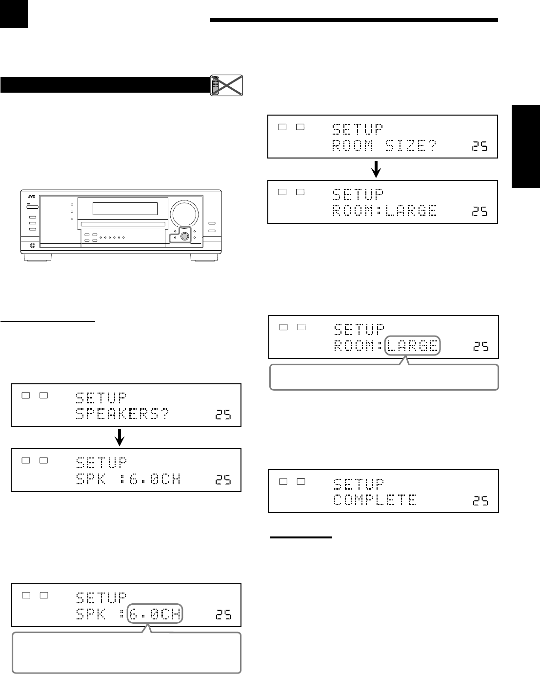
25
Français
Configuration des enceintes
La configuration rapide des enceintes (Quick Speaker Setup) vous
permet d’enregistrer facilement et rapidement la taille des enceintes
et la distance des enceintes en fonction de votre pièce d’écoute afin
de créer le meilleur effet Surround possible.
•Vous pouvez aussi enregistrer chaque information d’enceinte
manuellement.
Pour les détails, référez-vous à la page 27.
Avant de commencer, rappelez-vous...
Il y a un temps limite pour réaliser les étapes suivantes. Si le réglage
est annulé avant la fin, recommencez à partir de l’étape 1.
Sur le panneau avant:
1. Appuyez sur QUICK SPEAKER SETUP.
“SETUP” et “SPEAKERS?” apparaissent sur l’affichage, puis le
réglage initial pour le nombre total d’enceintes connectées
(canaux) apparaît.
2. Tounez MULTI JOG pour choisir le nombre
approprié d’enceintes connectées (nombre de
canaux d’enceinte).
Le nombre de canaux d’enceinte change comme suit.
•Pour les détails sur le nombre des canaux d’enceinte, référez-vous
à “Nombre d’enceintes (canaux) et leur taille” à la page 26.
* “6.0CH” est le réglage initial.
3. Appuyez sur MULTI JOG (PUSH SET).
“ROOM SIZE?” apparaît sur l’affichage, puis le réglage initial
de la taille de la pièce apparaît.
4. Tournez MULTI JOG pour choisir la taille
appropriée de la pièce par rapport à votre pièce
d’écoute.
La taille de la pièce change comme suit.
•Pour choisir la taille appropriée de la pièce, référez-vous à
“Taille de la pièce et distance des enceintes” à la page 26.
* “LARGE” est le réglage initial.
5. Apppuyez sur MULTI JOG (PUSH SET).
“COMPLETE” apparaît sur l’affichage, puis l’affichage retourne
à l’indication de la source.
•La configuration des enceintes est maintenant en service.
Remarque:
Cette procédure ne sera pas complète si vous l’arrêtez au milieu.
Remote
NOT
VOLUME
LINEAR PCM
LR
ANALOG
SPEAKERS 1
VOLUME
LINEAR PCM
LR
ANALOG
SPEAKERS 1
VOLUME
L R
ANALOG
SPEAKERS 1
2.0CH “ 2.1CH “ 3.0CH “ 3.1CH “ 4.0CH “
4.1CH “ 5.0CH “ 5.1CH “ 6.0CH* “ 6.1CH “
7.0CH “ 7.1CH “ (Retour au début)
VOLUME
LINEAR PCM
LR
ANALOG
SPEAKERS 1
VOLUME
LINEAR PCM
LR
ANALOG
SPEAKERS 1
VOLUME
LINEAR PCM
LR
ANALOG
SPEAKERS 1
SMALL “ MID “ LARGE* “ (Retour au début)
VOLUME
LINEAR PCM
LR
ANALOG
SPEAKERS 1
Réglages de base
Certains des réglages suivants doivent être effectués après la connexion et la disposition des enceintes tandis que
d’autres rendront les opérations plus simples. Vous pouvez utiliser QUICK SPEAKER SETUP pour faciliter la
configuration de vos enceintes.
FR25-30_8030&7030[C]f.pm6 03.2.12, 6:02 PM25
26
Français
Nombre d’enceintes (canaux) et leur taille
Vous pouvez trouver comment la taille de chaque enceinte est
définie en fonction du nombre d’enceintes connectées (nombre de
canaux (CH) d’enceinte) choisi.
Dans le tableau suivant, “L” signifie “enceinte avant gauche”, “R”
“enceinte avant droite”, “C” “enceinte centrale”, “LS” “enceinte
Surround gauche”, “RS” “enceinte Surround droite”, “SB” “enceinte
Surround arrière” et “SUBWFR” “caisson de grave”.
•Le caisson de grave est compté comme 0,1 canal.
Taille des enceintes connectées
CH L R C LS RS SB SUBWFR
2,0
LARGE LARGE NONE NONE NONE NONE NO
2,1
SMALL SMALL NONE NONE NONE NONE YES
3,0
LARGE LARGE SMALL NONE NONE NONE NO
3,1
SMALL SMALL SMALL NONE NONE NONE YES
4,0
LARGE LARGE NONE SMALL SMALL NONE NO
4,1
SMALL SMALL NONE SMALL SMALL NONE YES
5,0
LARGE LARGE SMALL SMALL SMALL NONE NO
5,1
SMALL SMALL SMALL SMALL SMALL NONE YES
6,0
LARGE LARGE SMALL SMALL SMALL SMALL NO
6,1
SMALL SMALL SMALL SMALL SMALL SMALL YES
7,0
LARGE LARGE SMALL SMALL SMALL SMALL*NO
7,1
SMALL SMALL SMALL SMALL SMALL SMALL*YES
* Ce réglage est affecté aux deux enceintes.
Taille de la pièce et distance des enceintes
En fonction de la taille de la pièce choisie, la distance de chaque
enceinte en service est réglée comme suit:
LARGE Enceinte Distance
L 3.0 m (10 ft)
R 3.0 m (10 ft)
C 3.0 m (10 ft)
LS 3.0 m (10 ft)
RS 3.0 m (10 ft)
SB 3.0 m (10 ft)
MID Enceinte Distance
L 2.7 m (9 ft)
R 2.7 m (9 ft)
C 2.4 m (8 ft)
LS 2.1 m (7 ft)
RS 2.1 m (7 ft)
SB 1.8 m (6 ft)
SMALL Enceinte Distance
L 2.4 m (8 ft)
R 2.4 m (8 ft)
C 2.1 m (7 ft)
LS 1.5 m (5 ft)
RS 1.5 m (5 ft)
SB 1.2 m (4 ft)
Éléments des réglages de base
Sur les pages suivantes, vous pouvez ajuster les réglages suivants:
Élément Pour Voir page
SUB WOOFER
*1Enregistrer le caisson de grave. 27
FRONT SPEAKER
*1
Enregistrer la taille des enceintes avant.
27
CNTR SPEAKER
*1
Enregistrer la taille de l’enceinte centrale.
27
SURR SPEAKER
*1
Eregister la taille des enceintes Surround.
27
SBACK SPEAKER
*1Enregistrer la taille des enceintes
Surround arrière. 27
SBACK OUT
*1Enregistrer le nombre d’enceintes
Surround arrière connectées. 27
DIST UNIT
Choisir l’unité de mesure pour la
distance des enceintes. 28
FRONT DISTANCE
*1Enregistrer la distance des enceintes
avant à votre point d’écoute. 28
CNTR DISTANCE
*1Enregistrer la distance de l’enceinte
centrale à votre point d’écoute. 28
SURR DISTANCE
*1Enregister la distance des enceintes
Surround à votre point d’écoute. 28
SBACK DISTANCE
*1Enregistrer la distance des enceintes
Surround arrière à votre point
d’écoute. 28
S WFR OUTPUT
Choisir le son émis par le caisson
de grave. 28
CROSS OVER
Choisir la fréquence de coupure
du caisson de grave. 28
LFE ATTENUATE
Atténuer les sons graves (LFE). 29
DUAL MONO
Choisir le canal sonore mono
double. 29
DGTL IN COAX
Choisir l’appareil connecté à
la prise coaxiale numérique. 29
DGTL IN OPTICAL
*2Choisir les appareils connectés
aux prises optiques numériques. 29
VIDEO IN DVD
Choisir le type de prise vidéo
utilisée par le lecteur de DVD. 30
VIDEO IN DBS
Choisir le type de prise vidéo
utilisée par le tuner DBS. 30
ONE TOUCH OPE
Mémoriser le niveau de volume
pour chaque source. 30
Remarques:
*1
Ces éléments peuvent être réglés en utilisant la configuration
rapide.
*2
Ce réglage est uniquement pour le RX-8030VBK.
Pour le RX-7030VBK, il est réglé automatiquement en fonction du
réglage “DGTL IN COAX”.
FR25-30_8030&7030[C]f.pm6 03.2.12, 6:02 PM26
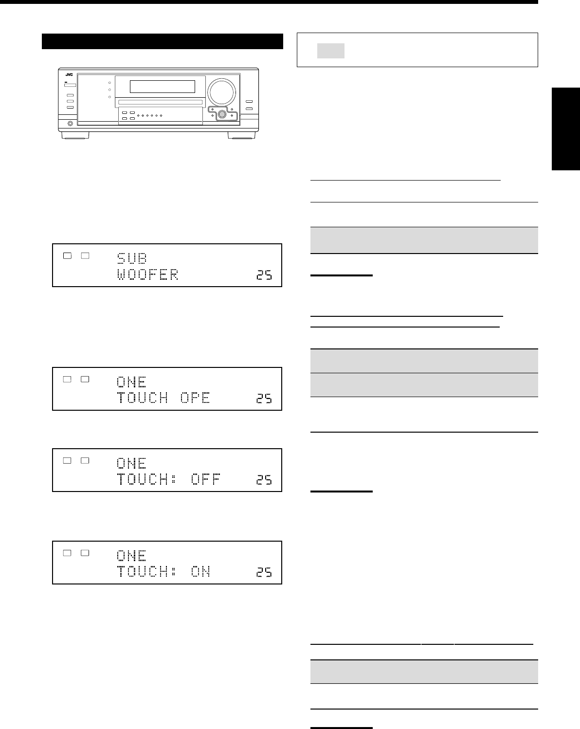
27
Français
Procédure de base
Avant de commencer, rappelez-vous...
Il y a un temps limite pour réaliser les étapes suivantes. Si le réglage
est annulé avant la fin, recommencez à partir de l’étape 1.
Ex. Quand le fonctionnement monotouche est réglé sur “ON”.
1. Appuyez sur SETTING.
Le dernier élément choisi apparaît sur l’affichage.
2. Tournez MULTI JOG jusqu’à ce que l’élément
souhaité apparaisse sur l’affichage.
•Dans cet exemple, choisissez “ONE TOUCH OPE”. Pour
connaître les éléments disponibles, référez-vous à la liste
“Éléments des réglages de base” à la page 26.
3. Appuyez sur MULTI JOG (PUSH SET).
Le réglage actuel de l’élément choisi apparaît sur l’affichage.
4. Tournez MULTI JOG jusqu’à ce que le réglage
souhaité apparaisse sur l’affichage.
5. Appuyez sur EXIT.
6. Répétez les étapes 2 à 5 pour régler, si nécessaire,
d’autres éléments.
7. Appuyez sur EXIT.
L’indication de la source réapparaît sur l’affichage.
Réglage des enceintes
Pour obtenir le meilleur son Surround possible avec les modes
Surround et DSP, il faut enregistrer des informations sur la
disposition des enceintes après que leur connexion est terminée.
•Si vous avez utilisé la configuration rapide à la page 25, ce réglage
n’est pas nécessaire.
7
Réglage du caisson de grave—SUB WOOFER
Choisissez si un caisson de grave est connecté ou non.
YES: Choisissez ce réglage quand un caisson de grave est
connecté.
NO: Choisissez ce réglage quand aucun caisson de grave
n’est connecté.
Remarque:
Si “NO” a été choisi pour le caisson de grave, il n’est pas possible
d’utiliser SUBWOOFER OUT ON/OFF sur le panneau avant.
7
Taille des enceintes—FRONT SPEAKER, CNTR
SPEAKER, SURR SPEAKER, SBACK SPEAKER
Choisissez la taille pour chaque enceinte connectée.
LARGE*1:Choisissez ce réglage quand la taille est
relativement grande.
SMALL*2:Choisissez ce réglage quand la taille est
relativement petite.
NONE: Choisissez ce réglage si vous n’avez pas connecté
d’enceinte (ne peut pas être choisi pour les
enceintes avant).
*1Réglage initial pour les enceintes avant.
*2Réglage initial pour l’enceinte centrale et les enceintes
Surround arrière.
Remarques:
•Gardez à l’esprit les choses suivantes comme référence lors de
l’ajustement.
–Si la taille du haut-parleur en cône intégré à votre enceinte
est plus grande que 12 cm (4
3
/
4
pouces), choisissez
“LARGE” et s’il est plus petit que 12 cm (4
3
/
4
pouces),
choisissez “SMALL”.
•Si vous avez choisi “NO” pour le caisson de grave, vous pouvez
choisir uniquement “LARGE” pour les enceintes avant.
•Si vous avez choisi “SMALL” pour les enceintes avant, vous ne
pouvez pas choisir “LARGE” pour l’enceinte centrale, Surround
et Surround arrière.
•Si vous avez choisi “SMALL” pour les enceintes Surround, vous ne
pouvez pas choisir “LARGE” pour les enceintes Surround arrière.
•Si vous avez choisi “NONE” pour les enceintes Surround, les
enceintes Surround arrière sont réglées sur “NONE”.
7
Quantité d’enceintes Surround arrière—SBACK OUT
Choisissez le nombre d’enceintes Surround arrière connectées.
1SPK: Choisissez ce réglage pour utiliser 1 enceinte Surround
arrière.
2SPK: Choisissez ce réglage pour utiliser 2 enceintes Surround
arrière.
Remarque:
Si vous avez choisi “NONE” pour les enceintes Surround arrière
(voir ci-dessus), ce réglage n’est pas disponible.
: Indique le réglage initial dans les tableaux
suivants.
VOLUME
LINEAR PCM
LR
ANALOG
SPEAKERS 1
VOLUME
LINEAR PCM
LR
ANALOG
SPEAKERS 1
VOLUME
LINEAR PCM
LR
ANALOG
SPEAKERS 1
VOLUME
ONE TOUCH OPERATION
LINEAR PCM
LR
ANALOG
SPEAKERS 1
FR25-30_8030&7030[C]f.pm6 03.2.12, 6:02 PM27
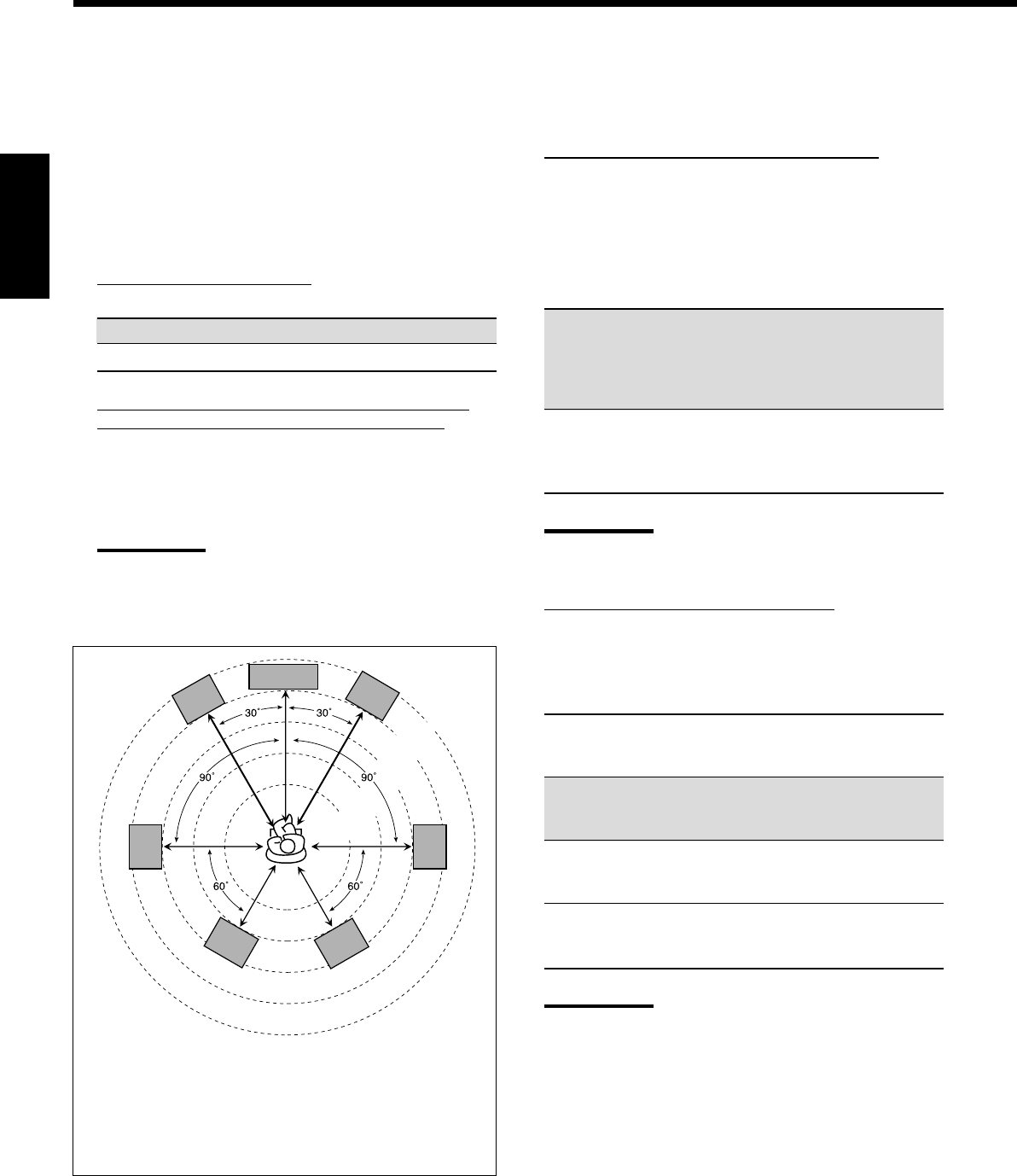
28
Français
Réglage de la distance des enceintes
La distance de votre point d’écoute aux enceintes est un autre
élément important pour obtenir le meilleur son possible des modes
Surround et DSP. Vous devez régler la distance de votre point
d’écoute aux enceintes.
En se référant à la distance aux enceintes, cet appareil règle
automatiquement le temps de retard du son pour chaque enceinte de
façon que le son de toutes les enceintes vous atteigne en même temps.
•Si vous avez utilisé la configuration rapide de la page 25, ce
réglage n’est pas nécessaire.
7
Unité de mesure—DIST UNIT
Choisissez l’unité de mesure vous souhaitez utiliser.
meter: Choisissez ce réglage pour régler la distance en mètres.
feet: Choisissez ce réglage pour régler la distance en pieds.
7
Distance des enceintes—FRONT DISTANCE, CNTR
DISTANCE, SURR DISTANCE, SBACK DISTANCE
Réglez la distance à partir du point d’écoute dans une plage de
0,3 m (1 pied) à 9,0 m (30 pieds), par intervalle de 0,3 m (1 pied).
•À l’expédition de l’usine, la distance pour chaque enceinte est
réglée sur “3.0 m (10 ft)”.
Remarques:
•Vous ne pouvez pas réglage la distance des enceintes pour
lesquelles vous avez choisi “NONE” (voir page 27).
•Ce réglage ne peut pas être utilisé avec le mode de lecture
DVD MULTI.
Ex. Dans le cas ci-dessus, réglez la distance des enceintes
comme suit:
Enceintes avant: 3.0 m (10 ft)
Enceinte centrale: 3.0 m (10 ft)
Enceintes Surround: 2.7 m (9 ft)
Enceintes Surround arrière: 2.4 m (8 ft)
Réglage des sons graves
Vous pouvez ajuster précisément le caisson de grave et les sons
graves selon vos préférences.
7
Sortie du caisson de grave—S WFR OUTPUT
Vous pouvez sélectionner le type de signal qui sera transmis par
le caisson de grave. En d’autres termes, vous pouvez choisir si
les éléments des graves des canaux des enceintes avant sont
transmis par le caisson de grave sans tenir compte du réglage de
la taille des enceintes avant (“SMALL” ou “LARGE”).
Choisissez un des réglages suivants:
LFE: Choisissez ce réglage pour transmettre
seulement des signaux LFE (lors de la
reproduction d’un support Dolby Digital et DTS)
et les éléments des graves des petites enceintes
par le caisson de grave.
LFE+MAIN: Choisissez ce réglage pour toujours ajouter les
éléments des graves des canaux des enceintes
avant (MAIN) au réglage ci-dessus (LFE), et
pour les transmettre par caisson de grave.
Remarque:
Si vous avez choisi “NO” pour le caisson de grave, cette fonction
n’est pas disponible.
7
Fréquence de transition—CROSS OVER
Quand vous utilisez un caisson de grave, vous pouvez choisir la
fréquence de transition pour les petites enceintes utilisées.
Choisir un des niveaux de fréquence de transition en
fonction de la taille des petites enceintes connectées.
80Hz: Choisissez ce réglage quand le haut-parleur en cône
intégré à votre enceinte est d’environ 12 cm
(4 3/4 pouces).
100Hz: Choisissez ce réglage quand le haut-parleur en cône
intégré à votre enceinte est d’environ 10 cm
(3 15/16 pouces).
120Hz: Choisissez ce réglage quand le haut-parleur en cône
intégré à votre enceinte est d’environ 8 cm
(3 3/16 pouces).
150Hz: Choisissez ce réglage quand le haut-parleur en cône
intégré à votre enceinte est d’environ 6 cm
(2 3/8 pouces).
Remarques:
•Si vous avez choisi “LARGE” pour toutes les enceintes actives
(voir page 27), cette fonction est réglée sur “OFF”.
•La fréquence de transition n’est pas valide pour le mode de
lecture DVD MULTI, All Channel Stereo, HEADPHONE et
3D HEADPHONE.
2.1 m
(7 ft)
2.4 m
(8 ft)
2.7 m
(9 ft)
3.0 m
(10 ft)
3.3 m
(11 ft)
C
LR
LS RS
LSB RSB
FR25-30_8030&7030[C]f.pm6 03.2.12, 6:02 PM28
29
Français
7
Atténuateur d’effet basse fréquence—LFE ATTENUATE
Si les sons graves sont déformés lors de la reproduction d’un
support codé avec Dolby Digital ou DTS, réglez le niveau LFE
pour éliminer le problème.
Choisissez un des réglages suivants:
0dB: Normalement, choisissez ce réglage.
−−
−−
−10dB: Choisissez ce réglage quand les sons graves sont
déformés.
Sélection du canal principal ou du sous-canal
—DUAL MONO
Sélectionnez les sons de lecture (canal).
MAIN: Choisissez ce réglage pour reproduire le canal
principal (Ch1).*1
L’indicateur de signal “L” s’allume quand ce canal
est reproduit.
SUB: Choisissez ce réglage pour reproduire le sous-canal
(Ch2).*1
L’indicateur de signal “R” s’allume quand ce canal
est reproduit.
ALL: Choisissez ce réglage pour reproduire le canal
principal et les sous-canaux (Ch1/Ch2).*1
Les indicateurs de signal “L” et “R” s’allument quand
ces canaux sont reproduits.
Remarques:
•Le format Dual Mono n’est pas le même que celui des
émissions bilingues ou MTS (Multichannel Television Sound)
utilisé pour les programmes de télévision. Ce réglage ne prend
donc pas effet quand vous regardez ces programmes bilingues
ou MTS.
*1
Les signaux Dual Mono peuvent être entendus à partir des
enceintes suivantes—L (enceinte avant gauche), R (enceinte
avant droite) et C (enceinte centrale)—quel que soit le réglage
Surround actuel.
Réglage des prises d’entrée numériques
Quand vous utilisez les prises d’entrée numériques, vous devez
enregistrer quels appareils vous avez connecté aux prises numériques.
7
Prise coaxiale numérique—DGTL IN COAX
Choisissez l’appareil connecté à la prise coaxiale numérique
(DIGITAL IN 1).
•Pour le RX-8030VBK: DVD (réglage initial), MD*, CDR,
TV (ou DBS**) ou CD.
•Pour le RX-7030VBK: DVD (réglage initial), CD, TV (ou
DBS**) ou CDR.
7
Prises optiques numériques—DGTL IN OPTICAL
Pour le RX-8030VBK:
Choisissez les appareils connectés aux prises optiques
numériques (DIGITAL IN 2 – 4).
•Quand vous tournez MULTI JOG, les prises d’entrée optique
numérique sont réglées pour utiliser les appareils numériques
suivants:
Quand “DIGITAL IN 1 (DGTL IN COAX)” est réglé sur “DVD”
2: CD 3: TV (ou DBS** ) 4: CDR “
2: CD 3: TV (ou DBS**) 4: MD* “
2: CD 3: MD* 4: CDR “
2: MD* 3: TV (ou DBS** ) 4: CDR “
(retour au début)
Quand “DIGITAL IN 1 (DGTL IN COAX)” est réglé sur “CD”
2: DVD 3: TV (ou DBS**) 4: CDR “
2: DVD 3: TV (ou DBS**) 4: MD* “
2: DVD 3: MD* 4: CDR “
2: MD* 3: TV (ou DBS**) 4: CDR “
(retour au début)
Quand “DIGITAL IN 1 (DGTL IN COAX)” est réglé sur “TV”
ou “DBS”**
2: CD 3: DVD 4: CDR “
2: CD 3: DVD 4: MD* “
2: CD 3: MD* 4: CDR “
2: MD* 3: DVD 4: CDR “
(retour au début)
Quand “DIGITAL IN 1 (DGTL IN COAX)” est réglé sur “CDR”
2: CD 3: TV (ou DBS**) 4: DVD “
2: CD 3: TV (ou DBS**) 4: MD* “
2: CD 3: MD* 4: DVD “
2: MD* 3: TV (ou DBS**) 4: DVD “
(retour au début)
Quand “DIGITAL IN 1 (DGTL IN COAX)” est réglé sur “MD”*
2: CD 3: TV (ou DBS**) 4: CDR “
2: CD 3: TV (ou DBS**) 4: DVD “
2: CD 3: DVD 4: CDR “
2: DVD 3: TV (ou DBS**) 4: CDR “
(retour au début)
*
Lors de la connexion d’un enregistreur de MD à la prise
d’entrée numérique, changez le nom de source de “TAPE”
sur “MD” (voir page 21).
**
Si vous avez changé le nom de source de “TV” sur “DBS”,
“DBS” apparaît (voir page 21).
Avec le mode Surround en service
Réglage Sans Surround Réglage de l’enceinte centrale
Dual Mono SMALL/LARGE NONE
LRLCRL R
MAIN Ch 1 Ch 1 — Ch 1 — Ch 1 Ch1
SUB Ch 2 Ch 2 — Ch 2 — Ch 2 Ch 2
ALL Ch 1 Ch 2 — Ch 1+Ch 2 — Ch 1+Ch 2 Ch 1+Ch 2
FR25-30_8030&7030[C]f.pm6 03.2.12, 6:02 PM29

30
Français
Mémorisation du niveau de volume pour chaque
source
Cet appareil mémorise beaucoup de réglages séparément pour
chaque source.
De plus, vous pouvez mémoriser le niveau de volume pour chaque
source en même temps que les autres réglages mémorisés—
Fonctionnement monotouche.
7
Fonctionnement monotouche—ONE TOUCH OPE
Choisissez un des réglages suivants:
ON: Choisissez ce réglage pour mémoriser le niveau de
volume séparément pour chaque source. (L’indicateur
ONE TOUCH OPERATION s’allume sur l’affichage.)
Cet ampli-tuner mémorise le niveau de volume—
•quand vous changez la source.
•quand vous changez le nom de la source.
OFF: Choisissez ce réglage pour ne pas mémoriser le niveau
de volume.
Pour rappeler le niveau de volume
Quand l’indicateur ONE TOUCH OPERATION est allumé, le
niveau de volume de la source actuellement choisie est rappelé
quand la source est choisie.
Pour annuler le fonctionnement monotouche
Réglez le fonctionnement monotouche sur “OFF” de façon que
l’indicateur ONE TOUCH OPERATION s’éteigne.
Pour le RX-7030VBK:
Quand vous réglez les appareils connectés à la prise coaxiale
numérique (DIGITAL IN 1), les prises optiques (DIGITAL IN 2
– 4) sont réglées automatiquement sur les appareils donnés
ci-dessous.
Quand “DIGITAL IN 1 (DGTL IN COAX)” est réglé sur “DVD”
2: CD 3: TV (ou DBS*) 4: CDR
Quand “DIGITAL IN 1 (DGTL IN COAX)” est réglé sur “CD”
2: DVD 3: TV (ou DBS*) 4: CDR
Quand “DIGITAL IN 1 (DGTL IN COAX)” est réglé sur “TV”
ou “DBS”*
2: DVD 3: CD 4: CDR
Quand “DIGITAL IN 1 (DGTL IN COAX)” est réglé sur “CDR”
2: DVD 3: CD 4: TV (ou DBS*)
*
Si vous avez changé le nom de source de “TV” sur “DBS”,
“DBS” apparaît (voir page 21).
Réglage de l’entrée en composantes vidéo
Si les entrées en composantes vidéo sont utilisées pour la connexion
du lecteur de DVD et/ou le tuner DBS, il faut enregistrer le type de
prises d’entrée.
Si vous n’avez pas choisi les prises d’entrée vidéo appropriées, le
système de commande à distance AV COMPU LINK ne peut pas
fonctionner correctement. (Voir page 42).
7
Pour le lecteur de DVD—VIDEO IN DVD
Choisissez un des réglages suivants:
COMPNT: Choisissez ce réglage si le lecteur de DVD est
connecté aux prises d’entrée en composantes vidéo.
S/C: Choisissez ce réglage si le lecteur de DVD est
connecté aux prises d’entrée vidéo composites ou
S-vidéo.
7
Pour le tuner DBS—VIDEO IN DBS
Choisissez un des réglages suivants:
COMPNT: Choisissez ce réglage si le tuner DBS est
connecté aux prises d’entrée en composantes vidéo.
S/C: Choisissez ce réglage si le tuner DBS est connecté
aux prises d’entrée vidéo composites ou S-vidéo.
FR25-30_8030&7030[C]f.pm6 03.2.12, 6:02 PM30
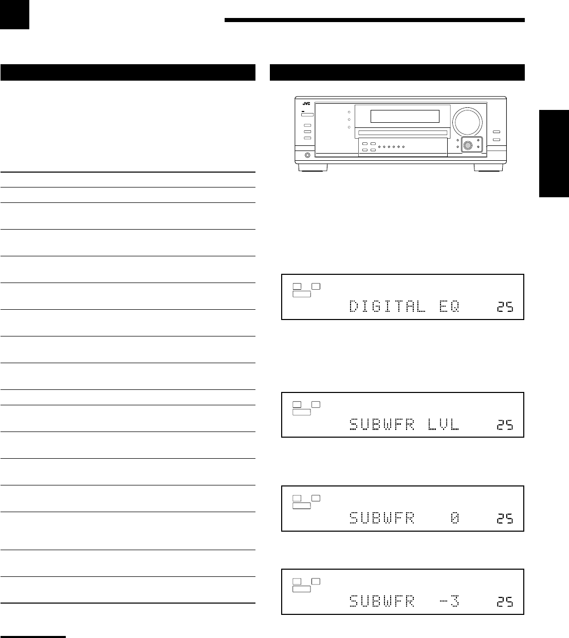
31
Français
Ajustment du son
Vous pouvez ajuster le son selon vos préférences après avoir terminé les réglages de base.
Procédure de base
Avant de commencer, rappelez-vous...
Il y a un temps limite pour réaliser les étapes suivantes. Si le réglage
est annulé avant la fin, recommencez à partir de l’étape 1.
Ex. Lors de l’ajustement du niveau du caisson de grave sur “– 3”.
1. Appuyez sur ADJUST.
Le dernier élément choisi apparaît sur l’affichage.
2. Tournez MULTI JOG jusqu’à ce que l’élément
souhaité apparaisse sur l’affichage.
•Dans cet exemple, choisissez “SUBWFR LVL”. Pour
connaître les éléments disponibles, référez-vous à la liste de la
colonne de gauche.
3. Appuyez sur MULTI JOG (PUSH SET).
Le réglage (ou le niveau) actuel de l’élément choisi apparaît sur
l’affichage.
4. Tournez MULTI JOG pour choisir le réglage
souhaité ou réaliser l’ajustement souhaité.
5. Appuyez sur EXIT.
6. Répétez les étapes 2 à 5 pour régler, si nécessaire,
d’autres éléments.
7. Appuyez sur EXIT.
L’indication de la source réapparaît sur l’affichage.
Éléments des réglages de base
Sur les pages suivantes, vous pouvez ajuster les éléments décrits
ci-dessous:
•Vous pouvez uniquement ajuster les éléments applicables au mode
sonore actuel.
•Si la fonction Analog Direct est en service, vous ne pouvez
réaliser aucun ajustement sonore.
Éléments Pour Voir page
DIGITAL EQ Ajuster la courbe d’égalisation. 32
SUBWFR LVL Ajuster le niveau de sortie du caisson
de grave. 32
FRONT L LVL Ajuster le niveau de sortie de
l’enceinte avant gauche. 32
FRONT R LVL Ajuster le niveau de sortie de
l’enceinte avant droite. 32
CENTER LVL Ajuster le niveau de sortie de
l’enceinte centrale. 32
SURR L LVL Ajuster le niveau de sortie de
l’enceinte Surround gauche. 32
SURR R LVL Ajuster le niveau de sortie de
l’enceinte Surround droite. 32
SBACK LVL Ajuster le niveau de sortie de
l’enceinte Surround arrière. 32
EFFECT*1Ajuster le niveau d’effet DAP. 33
ROOMSIZE*1Choisir la taille de la pièce pour
votre pièce d’écoute virtuelle. 33
LIVENESS*1Choisir le niveau de direct pour
votre pièce d’écoute virtuelle. 33
CTR TONE Rendre la tonalité centrale douce ou
nette. 33
PANORAMA*2Ajouter un effet sonore panoramique
avec une image de murs latéraux. 33
CNTR WIDTH*2Ajuster la localisation du canal
central entre l’enceinte centrale
et les enceintes avant gauche/droite. 33
DIMENSION*2Ajuster la position de la localisation
du son. 33
CNTR GAIN*3Ajuster la localisation sonore du
canal central. 33
Remarques:
*
1
Ajustable quand le mode DAP est en service.
*
2
Ajustable quand Pro Logic II Music est en service.
*
3
Ajustable quand Neo: 6 Music est en service.
VOLUME
LINEAR PCM
L
SUBWFR
R
ANALOG
SPEAKERS 1
VOLUME
LINEAR PCM
L
SUBWFR
R
ANALOG
SPEAKERS 1
VOLUME
LINEAR PCM
L
SUBWFR
R
ANALOG
SPEAKERS 1
VOLUME
LINEAR PCM
L
SUBWFR
R
ANALOG
SPEAKERS 1
FR31-33_8030&7030[C]f.pm6 03.2.12, 6:02 PM31
32
Français
Ajustement des niveaux de sortie des enceintes
Vous pouvez ajuster les niveaux de sortie des enceintes. La tonalité
de sort de chaque enceinte à l’exception du caisson de grave pour
vous permettre de vérifier la balance du niveau de sortie lors de
l’utilisation du mode Surround.
•Une fois que l’ajustement est réalisé, il est mémorisé pour chaque
source.
7
Enceintes ajustables
Choisissez et réglez les niveaux de sortie des enceintes suivants
dans une plage de –10 dB à +10 dB (“0 dB” est le réglage
initial):
SUBWFR LVL
:Choisissez ce réglage pour ajuster le niveau
de sortie du caisson de grave.
FRONT L LVL: Choisissez ce réglage pour ajuster le niveau
de sortie de l’enceinte avant gauche.
FRONT R LVL: Choisissez ce réglage pour ajuster le
niveau de sortie de l’enceinte avant droite.
CENTER LVL: Choisissez ce réglage pour ajuster le
niveau de sortie de l’enceinte centrale.
SURR L LVL: Choisissez ce réglage pour ajuster le niveau
de sortie de l’enceinte Surround gauche.
SURR R LVL: Choisissez ce réglage pour ajuster le niveau
de sortie de l’enceinte Surround droite.
SBACK LVL*:Choisissez ce réglage pour ajuster le niveau
de sortie de l’enceinte Surround arrière.
Remarques:
•Si vous avez choisi “NO” ou “NONE” pour une enceinte (voir
page 27), le niveau de sortie pour l’enceinte correspondante ne
peut pas être ajusté.
•Les niveaux de sortie de l’enceinte centrale et des enceintes
Suround gauche/droite sont ajustables pour le mode de lecture
DVD MULTI même si “NONE” a été choisi pour le réglage des
enceintes.
•Les niveaux de sortie des enceintes (sauf le niveau de sortie
du caisson de grave) ne sont pas ajustables quand la fonction
Analog Direct est en service. Pour ajuster le niveau de sortie du
caisson de grave, référez-vous à la page 19.
Ajustement des courbes d’égalisation
Vous pouvez ajuster les courbes d’égalisation selon vos préférences
•Une fois que l’ajustement est réalisé, il est mémorisé pour chaque
source.
7
Ajustement de l’égalisation—DIGITAL EQ
Vous pouvez ajuster cinq bandes de fréquence (63 Hz, 250 Hz,
1 kHz, 4 kHz, 16 kHz) dans une plage de –8 dB à +8 dB (“0
dB” est le réglage initial) par pas de 2 dB.
•Quand l’ajustement est terminé, l’indicateur DIGITAL EQ
s’allume sur l’affichage.
Pour aplatir la courbe d’égalisation, réglez toutes les bandes
de fréquence sur “0 dB” à l’étape 4 de “Procédure de base” (à la
page 31). L’indicateur DIGITAL EQ s’éteint de l’affichage.
Remarques:
•Quand la fonction Analog Direct est utilisée, les courbes
d’égalisation numérique ne peuvent pas être ajustées.
•L’égalisation numérique affecte uniquement le son des enceintes
avant.
Vous pouvez aussi utiliser la télécommande pour ajuster
l’égalisation.
1. Appuyez sur SOUND.
Les touches numériques peuvent être utilisées pour les
ajustements sonores.
2. Appuyez répétitivement sur DIGITAL EQ (égalisation)
pour choisir la fréquence centrale que vous souhaitez
ajuster.
•Chaque fois que vous appuyez sur la touche, la fréquence
centrale avec son niveau actuel apparaît sur l’affichage.
3. Appuyez répétitivement sur LEVEL + ou – pour ajuster
le niveau de la fréquence centrale.
L’indicateur DIGITAL EQ s’allume sur l’affichage.
•Le niveau de fréquence change de –8 dB à +8 dB par pas
de 2 dB.
4. Répétez les étapes 2 et 3 pour ajuster les autres
fréquences centrales.
231
564
89
7/P
0
+10
10/0
FR31-33_8030&7030[C]f.pm6 03.2.12, 6:02 PM32
33
Français
Vous pouvez aussi utiliser la télécommande pour ajuster le niveau
de sortie des enceintes.
Lors de l’utilisation de la télécommande, vous pouvez réaliser
l’ajustement en écoutant la tonalité de test.
1. Appuyez sur SOUND.
Les touches numériques peuvent être utilisées pour les
ajustements sonores.
2. Appuyez sur TEST afin de vérifier si le son
peut être entendu à un niveau égal à partir de
toutes les enceintes.
Une tonalité de test sort des enceintes dans l’ordre suivant:
•Aucune tonalité de test ne sort des enceintes hors service et
du caisson de grave.
FRNT L (enceinte avant gauche)
=
CENTER (enceinte
centrale)
=
FRNT R (enceinte avant droite)
=
SURR R
(enceinte Surround droite)
=
S BACK (enceinte Surround
arrière)
=
SURR L (enceinte Surround gauche)
=
(retour au début)
3. Choisissez l’enceinte que vous souhaitez ajuster.
•Pour choisir l’enceinte avant gauche, appuyez sur FRONT•L.
•Pour choisir l’enceinte centrale, appuyez sur CENTER.
•Pour choisir l’enceinte avant droite, appuyez sur FRONT•R.
•Pour choisir l’enceinte Surround droite, appuyez sur SURR•R.
•Pour choisir l’enceinte Surround arrière, appuyez sur
SURR BACK.
•Pour choisir l’enceinte Surround gauche, appuyez sur
SURR•L.
4. Appuyez sur LEVEL + ou LEVEL – pour ajuster le
niveau de sortie de l’enceinte (–10 dB à +10 dB).
5. Répétez les étapes 3 et 4 pour ajuster les autres niveaux
de sortie des enceintes.
6. Appuyez de nouveau sur TEST pour arrêter la tonalité de
test.
231
564
89
7/P
0
+10
10/0
Ajustement des paramètres du son pour les
modes Surround et DSP
Vous pouvez ajuster les paramètres du son des modes Surround et
DSP selon vos préférences.
•Quand l’enceinte centrale est réglée sur “NONE”, CTR TONE,
CNTR WIDTH et CNTR GAIN ne sont pas disponibles.
7
Paramètres ajustables
Vous pouvez ajuster les paramètres suivants:
Pour les modes Surround, DAP et All Channel Stereo (quand
l’enceinte centrale est connectée)
•Ce réglage est commun pour tous les modes Surround et
est mémorisé séparément pour les modes DSP.
CTR TONE: Permet d’ajuster la tonalité centrale. Plus le
nombre augmente plus les dialogues
deviennent clairs et les voix humaines passent
d’une tonalité douce à une tonalité nette.
(Normalement, choisissez “3 (réglage initial)”.
Plage d’ajustement: 1 à 5)
Pour les modes DAP
•Une fois que vous avez réalisé un ajustement, il est mémorisé
pour chaque mode DAP.
EFFECT: Permet d’ajuster le niveau d’effet DAP. Plus le
nombre augmente plus l’effet DAP devient
fort. (Normalement, choisissez “3 (réglage
initial)”. Plage d’ajustement: 1 à 5)
ROOMSIZE: Permet d’ajuster la taille virtuelle de la pièce.
Plus le nombre est grand, plus l’intervalle
entre les réflexions augmente et donne
l’impression de se trouver dans une pièce plus
grande. (Normalement, choisissez “3 (réglage
initial)”. Plage d’ajustement: 1 à 5)
LIVENESS: Permet d’ajuster l’effet de direct. Plus le
nombre augmente, plus le niveau
d’atténuation des réflexions par rapport au
temps diminue et l’acoustique passe d’un effet
“mort” à un effet de “direct”. (Normalement,
choisissez “3 (réglage initial)”. Plage
d’ajustement: 1 à 5)
Pour le Pro Logic II Music uniquement
PANORAMA: Choisissez “ON” pour ajouter un effet
“panoramique” au son avec une image de
murs latéraux. (Réglage initial: “OFF”)
CNTR WIDTH: Permet d’ajuster la localisation du canal
central entre l’enceinte centrale et les
enceintes gauche/droite. Plus le nombre
augmente, plus le son du canal central se
déplace vers les enceintes gauche et droite.
(Normalement, choisissez “3 (réglage initial)”.
Plage d’ajustement: OFF et 1 à 7)
DIMENSION: Permet d’ajuster la position de la localisation
du son. Plus le nombre augmente, plus la
localisation du son se déplace de l’avant vers
l’arrière. (Normalement, choisissez “4 (réglage
initial)”. Plage d’ajustement: 1 à 7)
Pour Neo:6 Music uniquement
CNTR GAIN: Permet d’ajuster la localisation du canal
central. Plus le nombre augmente, plus le
canal central est localisé clairement.
(Normalement, choisissez “0.2 (réglage
initial)”. Plage d’ajustement: 0 à 0.5)
FR31-33_8030&7030[C]f.pm6 03.2.12, 6:02 PM33
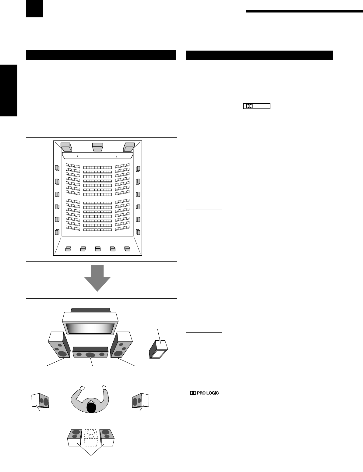
34
Français
Utilisation des modes Surround
Cet appareil permet de mettre en service une variété de modes Surround automatiquement. Les réglages de base et
les ajustements mémorisés (voir pages 25 à 33) sont appliqués.
Reproduction de l’ambiance d’un cinéma
Dans une salle de cinéma, beaucoup d’enceintes sont situées sur les
murs pour reproduire un son multi-surround impressionnant vous
atteignant de toutes les directions.
Avec toutes ces enceintes, la localisation du son et le mouvement du
son peuvent être exprimés.
Les modes Surround intégrés à cet ampli-tuner peuvent recréer à
peu près les mêmes son Surround que vous pourriez sentir dans une
vraie salle de cinéma—avec seulement cinq ou sept enceintes (plus
un caisson de grave).
Introduction des modes Surround
Dolby Digital*1
Dolby Digital est une méthode de compression de signal
numérique mise au point par Dolby Laboratories, et permet de
coder et de décoder des signaux multi-canaux (1 à 5,1 canaux).
•Quand un signal Dolby Digital est détecté par l’entrée
numérique, l’indicateur
DIGITAL
s’allume sur l’affichage.
Dolby Digital 5.1CH
La méthode de codage Dolby Digital 5,1CH (DOLBY D)
enregistre et compresse numériquement les signaux du canal avant
gauche, du canal avant droit, du canal central, du canal Surround
gauche, du canal Surround droit et du canal LFE (6 canaux en tout,
mais le canal LFE est compté comme 0,1 canal et par conséquent,
appelé 5,1 canaux).
Dolby Digital autorise les sons stéréo Surround et la fréquence de
coupure des enceintes Surround est réglée sur 20 kHz, un niveau
nettement supérieur aux 7 kHz du Dolby Pro Logic. De même, le
mouvement du son et “l’impression de direct” sont encore plus
accentuées qu’avec le Dolby Pro Logic.
Dolby Digital EX
Dolby Digital EX (DOLBY D EX) est un format de codage
Surround numérique qui ajoute des troisièmes canaux Surround,
appelés “Surround arrière”.
Par rapport au Dolby Digital 5,1CH conventionnel, ces nouveaux
canaux Surround arrière peuvent reproduire d’une façon plus
détaillée les mouvements derrière vous lors de la reproduction
d’une source vidéo. De plus, la localisation du son Surround
devient plus stable.
•Vous pouvez utiliser le Surround virtuel à 6,1 canaux (Virtual
6.1-channel Surround) lors de la lecture d’un support Dolby
Digital EX sans connecter les enceintes Surround arrière. Ce
mode Surround relocalise les canaux Surround arrière sur les
enceintes Surround de façon que vous puissiez ressentir un effet
Surround puissant de derrière.
L’indicateur VIRTUAL SB (Surround arrière) s’allume sur
l’affichage.
Dolby Pro Logic
Les formats codés Dolby Surround enregistrent les signaux du
canal avant gauche, du canal avant droit, du canal central et du
canal Surround (monaural) sur 2 canaux.
Le décodeur Dolby Pro Logic (PRO LOGIC) intégré à cet ampli-
tuner décode les signaux de ces 2 canaux en signaux des 4 canaux
d’origine (plus caisson de graves)—reproduction multi-canaux à
base matricielle.
•Quand le Dolby Pro Logic est mis en service, l’indicateur
s’allume sur l’affichage.
Caisson de
grave
Enceinte avant
gauche (L)
Enceinte avant droite
(R)
Enceinte
centrale (C)
Enceinte Surround arrière (LSB/RSB)
Enceinte
Surround gauche
(LS)
Enceinte
Surround droite
(RS)
FR34-40_8030&7030[C]f.pm6 03.2.12, 6:02 PM34
35
Français
DTS 96/24
Au cours de ces dernières années, il a eu un intérêt accru pour les
fréquences d’échantillonnage élevées pour l’enregistrement et la
lecture à domicile. Les fréquences d’échantillonnage plus élevées
permettent d’avoir une bande de fréquence plus large et une
profondeur de bit plus grande et permettent d’obtenir une
dynamique plus étendue.
DTS 96/24 est un format de signal numérique multi-canaux (fs 96
kHz/24 bits) introduit par Digital Theater Systems, Inc. pour recréer
chez soi “une meilleure qualité acoustique que les CD”.
•Quand les signaux DTS 96/24 sont détectés, l’indicateur 96/24
s’allume. Vous pouvez profiter entièrement la qualité du son à 5,1
canaux.
DTS Neo:6
DTS Neo:6 est une autre méthode de conversion qui a été mise au
point récemment pour créer à 6,1 canaux à partir de supports
multicanaux et de supports analogiques/numériques à deux canaux
en utilisant un décodeur matriciel numérique de haute précision pour
DTS-ES Matrix 6.1ch. Quand un des modes Neo:6 est mis en
service, l’indicateur NEO:6 s’allume sur l’affichage.
•Lors de la lecture d’un support analogique/numérique à 2 canaux,
cet ampli-tuner offre deux types de mode DTS Neo:6—Neo:6
Cinema (NEO:6 CINMA) et Neo:6 Music (NEO:6 MUSIC).
NEO:6CINMA: Convient pour visionner des films. Vous pouvez
recréer la même atmosphère avec un logiciel à deux
canaux qu’avec un logiciel à 6,1 canaux. Ce mode
permet également de reproduire un support codé
avec des formats Surround conventionnels.
NEO:6MUSIC: Convient pour la lecture de supports musicaux. Les
signaux des canaux avant contournent le décodeur
(de cette façon, il n’y a pas de perte de qualité
sonore) et les signaux Surround transmis dans les
autres enceintes étendent naturellement le champ
sonore.
Dolby Pro Logic II
Dolby Pro Logic II est un format de lecture à multi-canaux
permettant de convertir un support à deux canaux en 5 canaux (plus
caisson de graves). La méthode de conversion à base matricielle et
utilisée avec Dolby Pro Logic II ne limite pas la fréquence de
coupure des aigus du signal Surround et permet un son stéréo
Surround.
•Ce récepteur permet d’avoir deux types de modes Dolby Pro
Logic II—Pro Logic II Movie (PL II MOVIE) et Pro Logic II
Music (PL II MUSIC).
Quand Dolby Pro Logic II est en service, indicateur
s’allume sur l’écran d’affichage.
PLII MOVIE: Convient aux supports codés avec Dolby
Surround. Vous pouvez recréer un champ sonore
très proche de celui du son à 5,1 canaux discrets.
PLII MUSIC: Convient aux supports stéréo à 2 canaux. Vous
pouvez recréer un son large et profond.
DTS*2
DTS est une autre méthode de compression de signal numérique,
mise au point par Digital Theater Systems, Inc., qui permet de coder
et décoder des signaux multi-canaux (1 à 6,1 canaux).
•Quand un signal DTS est détecté par l’entrée numérique,
l’indicateur s’allume sur l’affichage.
DTS Digital Surround
Le DTS Digital Surround (DTS) est un autre format audio
numérique à 5,1 canaux discrets disponible sur les supports CD, LD
et DVD.
•Quand le réglage EX/ES est réglé sur “ON”, DTS Neo:6 (DTS
NEO:6) est mis en service lors de la lecture de supports DTS
multicanaux. Il crée la même ambiance Surround que pour les
supports à 6,1 canaux.
DTS Extended Surround (DTS-ES)
DTS-ES est un autre format de codage et décodage numérique des
signaux multi-canaux. Il améliore considérablement l’impression
d’ambiance ou Surround à 360 degrés ainsi que l’expression
spatiale en ajoutant un troisième canal Surround—canal arrière
Surround.
DTS-ES comprend deux formats de signal avec différentes
méthodes d’enregistrement du signal Surround—DTS-ES Discrete
6.1ch (ES DSCRETE) et DTS-ES Matrix 6.1ch (ES MATRIX).
DTS-ES Discrete 6,1ch a été conçu pour coder (et décoder) les
signaux à 6,1 canaux discrets et éviter les interférences avec chaque
canal.
DTS-ES Matrix 6,1ch a été conçu pour ajouter un canal Surround
supplémentaire aux 5,1 canaux du 5,1 DTS Digital Surround. Grâce
à cette méthode de codage/décodage matriciel, un canal “Surround
arrière” supplémentaire est codé (et décodé) et intégré dans les
signaux des canaux Surround à gauche et à droite.
•Vous pouvez utiliser le Surround virtuel à 6,1 canaux (Virtual 6.1-
channel Surround) lors de la lecture d’un support DTS-ES sans
connecter des enceintes Surround arrière. Ce mode Surround
relocalise le canal Surround arrière sur les enceintes Surround de
façon que vous puissiez quand même ressentir un effet Surround
de l’arrière.
L’indicateur VIRTUAL SB (Surround arrière) s’allume sur
l’affichage.
Qu’est-ce que le mode Dual Mono?
Le mode Dual Mono peut être compris facilement si vous pensez
aux émissions bilingues ou MTS (Multichannel Television
Sound) utilisées pour les programmes de télévision (cependant, le
format Dual Mono n’est pas identique à ces formats).
Ce format est maintenant adopté pour le Dolby Digital, DTS, etc.
Il autorise l’enregistrement séparé deux canaux indépendants
(appelés canal principal et sous-canal).
•Quand un signal Dual Mono est détecté, l’indicateur DUAL
s’allume. Vous pouvez alors choisir le canal que vous souhaitez
écouter (voir page 29).
Lors de l’utilisation du mode Surround, le son sort par les
enceintes en service nécessaires au mode Surround.
•Si les enceintes Surround et l’enceinte centrale sont réglées sur
“NONE” dans le réglage des enceintes, le mode 3D-PHONIC
original de JVC (qui a été mis au point pour créer un effet
Surround uniquement à partir des enceintes avant) est utilisé.
L’indicateur 3D-PHONIC s’allume sur l’affichage.
*1
Fabriqué sous licence de Dolby Laboratories. “Dolby”, “Pro Logic”
et le symbole double D sont des marques de commerce de Dolby
Laboratories.
*1
“DTS”, “DTS-ES Extended Surround” et “Neo:6” sont des
marques de commerce de Digital Theater Systems, Inc.
FR34-40_8030&7030[C]f.pm6 03.2.12, 6:02 PM35
36
Français
Modes Surround applicables à divers supports
Les modes Surround disponibles varient en fonction des réglages des enceintes et des signaux entrant.
Le tableau ci-dessous vous montre la relation entre les modes Surround et les signaux entrants (avec le réglage des enceintes Surround arrière
et de EX/ES).
•Le nombre entre parenthèses suivant le type de signal entrant indique le nombre de canaux avant et de canaux Surround. Pare exemple,
(3/2) signifie que les signaux sont codés avec trois signaux avant (gauche/droit/central) et deux signaux arrière (stéréo).
Type de signal entrant Réglage du canal Surround arrière Réglage EX/ES Mode Surround disponible
Dolby Digital EX 2SPK/1SPK AUTO/ON DOLBY D EX
OFF DOLBY D
NONE AUTO/ON DOLBY D (VIRTUAL SB)*1
OFF DOLBY D
Dolby Digital (3/2, 2/2) 2SPK/1SPK AUTO DOLBY D
ON DOLBY D EX
OFF DOLBY D
NONE Non disponible DOLBY D
Dolby Digital (3/1, 2/1) 2SPK/1SPK AUTO/ON/OFF DOLBY D
NONE Non disponible DOLBY D
Dolby Digital (1/0, 3/0) 2SPK/1SPK/NONE Non disponible DOLBY D
Dolby Digital (Dual Mono) 2SPK/1SPK/NONE Non disponible DUAL MONO
DTS-ES Discrete 6.1ch 2SPK/1SPK AUTO/ON ES DSCRETE
OFF DTS
NONE AUTO/ON DTS (VIRTUAL SB)*1
DTS-ES Matrix 6.1ch 2SPK/1SPK AUTO/ON ES MATRIX*2
DTS-ES 96/24 Matrix OFF DTS
NONE AUTO/ON DTS (VIRTUAL SB)*1 *2
OFF DTS
DTS, DTS 96/24 (3/2, 2/2) 2SPK/1SPK AUTO DTS
ON DTS NEO:6*2
OFF DTS
NONE Non disponible DTS
DTS (3/1, 2/1) 2SPK/1SPK AUTO/ON/OFF DTS
NONE Non disponible DTS
DTS (1/0, 3/0) 2SPK/1SPK/NONE Non disponible DTS
DTS (Dual Mono) 2SPK/1SPK/NONE Non disponible DUAL MONO
Type de signal entrant Mode Surround disponible
Analog/PCM / Dolby Digital (2/0)/ DTS (2/0) PL II MOVIE / PL II MUSIC / PRO LOGIC / NEO:6 CINMA / NEO:6 MUSIC
DVD MULTI Aucun
Mode 3D HEADPHONE—3D H PHONE
Vous pouvez profiter des modes Surround à travers le casque d’écoute.
Si vous appuyez sur SURROUND quand les enceintes avant 1 et 2 sont hors service, le mode 3D HEADPHONE (3D H PHONE) est mis
en service quel que soit le type de support reproduit. “3D H PHONE” apparaît sur l’affichage et les indicateurs DSP et HEADPHONE
s’allument aussi.
*1Surround virtuel à 6,1 canaux (Virtual 6.1-channel Surround)
Si vous avez connecté (et mis en service) des enceintes Surround, vous pouvez utiliser le Surround virtuel à 6,1 canaux lors de la lecture
de supports Dolby Digital EX ou DTS-ES sans avoir besoin de connecter des enceintes Surround arrière. Ce mode Surround relocalise le
canal Surround arrière sur les enceintes Surround de façon que vous puissiez quand même ressentir un effet Surround de l’arrière.
L’indicateur VIRTUAL SB (Surround arrière) s’allume sur l’affichage.
*2
Le traitement DTS 96/24 n’est
pas appliqué. Si vous
souhaitez l’appliquer, réglez
EX/ES sur “OFF”.
FR34-40_8030&7030[C]f.pm6 03.2.12, 6:02 PM36
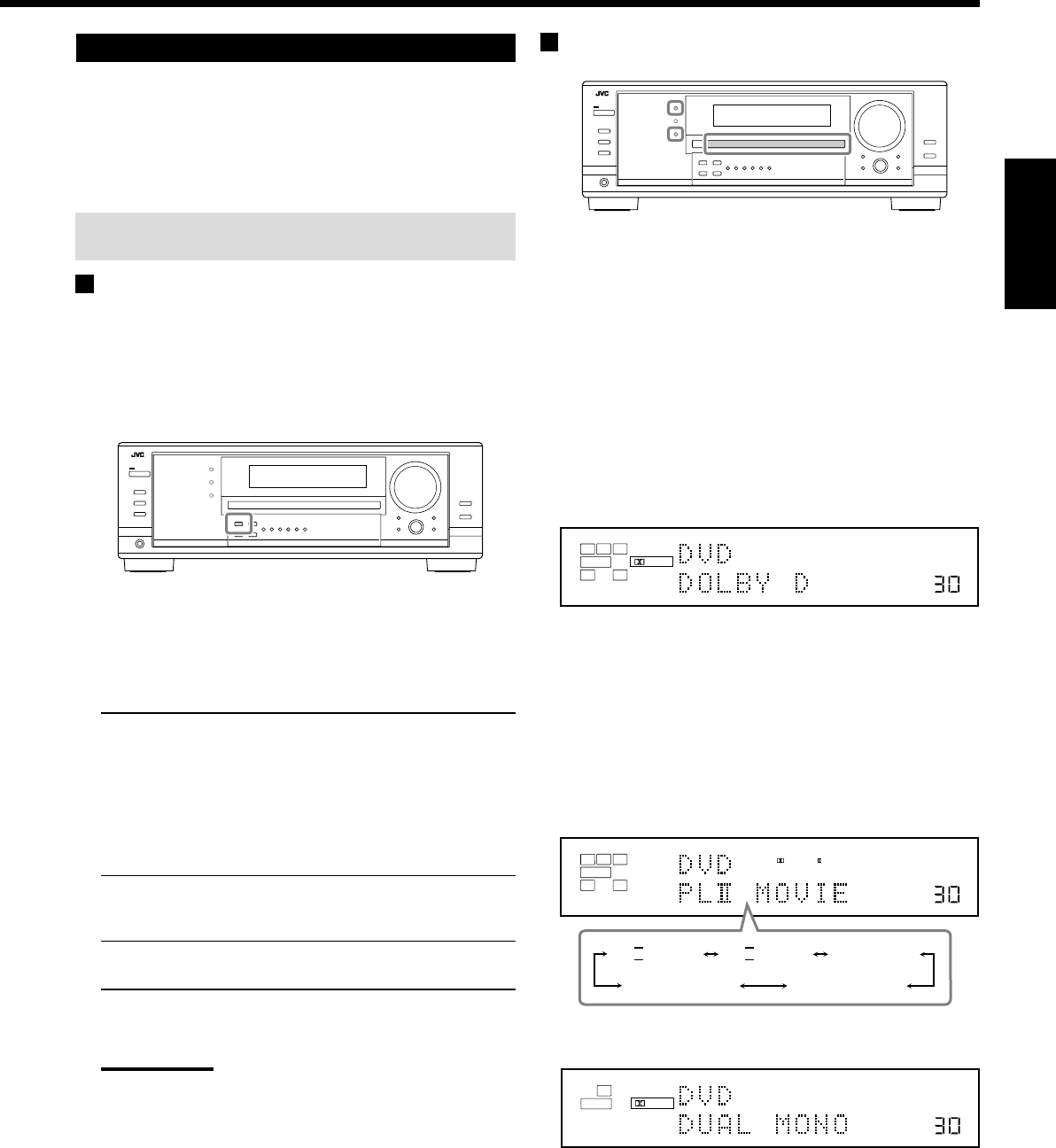
37
Français
Mise en service du mode Surround
Les modes Surround disponibles dépendant des réglages des
enceintes et des signaux entrant. (Voir page 36.)
Mettre en service un mode Surround pour une source rappelle
automatiquement les réglages et les ajustements mémorisés (voir
pages 25 à 33).
Vous pouvez aussi utiliser les touches sur la télécommande pour
les mêmes fonctions.
Mise en service du réglage EX/ES
Avec un support numérique multi-canaux, vous pouvez mettre en
service le mode de reproduction EX/ES (7,1 canaux).
•Une fois le mode de reproduction EX/ES (7,1 canaux) réglé, il est
conservé en mémoire pour être rappelé en même temps que le
mode Surround avec lequel peut s’appliquer le mode de
reproduction EX/ES (7,1 canaux) mémorisé.
Appuyez sur EX/ES pour choisir le réglage souhaité.
Le mode de reproduction EX/ES (7,1 canaux) actuellement choisi
apparaît sur l’affichage.
•Chaque fois que vous appuyez sur la touche, il change comme
suit:
EX/ES AUTO*:Le mode Surround approprié est appliqué en
fonction du signal d’entrée.
•Pour le Dolby Digital EX et DTS-ES, la
reproduction EX/ES (7,1 canaux) est
appliquée.
•Pour les supports codés avec 5,1 canaux
(ou moins), la reproduction à 5,1 canaux
est appliquée.
EX/ES ON*:Choisissez ce réglage pour appliquer la
reproduction EX/ES (7,1 canaux) aux
supports codés à 5,1 et 6,1 canaux.
EX/ES OFF: Choisissez ce réglage pour annuler la
reproduction EX/ES (7,1 canaux).
*
Si les enceintes Surround arrière ne sont pas connectées ou
sont hors service, le Surround virtuel à 6,1 canaux est appliqué.
Remarques:
•Quand le mode Surround est mis hors service, appuyer sur EX/
ES met en service un mode Surround approprié pour la source
actuelle.
•Quand une source analogique ou numérique à 2 canaux est
reproduite, vous pouvez ajuster le mode de reproduction EX/ES
(7,1 canaux) et mémoriser le réglage, mais il n’affectera pas la
source actuelle.
•Si la source est une source pour laquelle la reproduction EX/ES
(7,1 canaux) ne peut pas être appliquée, vous pouvez ajuster
les réglages et les mémoriser, mais les canaux reproduits
resteront inchangés.
Mise en service des modes Surround
1. Choisissez et reproduisez n’importe quelle source
autre que “DVD MULTI”.
•Assurez-vous que vous avez choisi le mode d’entrée
analogique ou numérique.
•Les modes Surround ne sont pas valides pour le mode de
lecture DVD MULTI.
2. Appuyez sur SURROUND pour mettre en service
le mode Surround.
•Pour les supports numériques multi-canaux (sauf les
supports à 2 canaux et Dual Mono), les signaux entrants
sont détectés automatiquement et le mode Surround approprié
est mis en service (référez-vous à la page 36 pour les détails).
–Si le mode de reproduction EX/ES (7,1 canaux) a été réglé
sur “AUTO” ou “ON”, un des modes de reproduction
EX/ES (7,1 canaux) est mis en service (référez-vous à la
colonne de gauche).
•Pour les sources analogiques et les supports numériques à
2 canaux, vous pouvez choisir un des modes Surround
suivants. Chaque fois que vous appuyez sur SURROUND, le
mode Surround change comme suit:
•Pour les supports Dual Mono, vous pouvez choisir le canal
que vous souhaitez écouter. (Voir page 29.)
Pour ajuster le niveau de sortie des enceintes, référez-vous aux
pages 32 et 33.
Pour annuler le mode Surround
Appuyez sur SURROUND/DSP OFF (ou sur SURR/DSP OFF sur la
télécommande). “SURR OFF” apparaît sur l’affichage.
Ex. Quand “DOLBY D” est mis en service.
VOLUME
LINEAR PCM
DIGITAL
L
SUBWFR
LS RS
CR
LFE
DIGITAL AUTO
SPEAKERS 1
VOLUME
LINEAR PCM
DIGITAL
L
SUBWFR
DUAL DIGITAL AUTO
SPEAKERS 1
VOLUME
LINEAR PCM
L
SUBWFR
R
ANALOG
PRO LOGIC
SPEAKERS 1
NEO:6CINMANEO:6MUSIC
PL
II
MOVIE PL
II
MUSIC PRO LOGIC
FR34-40_8030&7030[C]f.pm6 03.2.12, 6:02 PM37
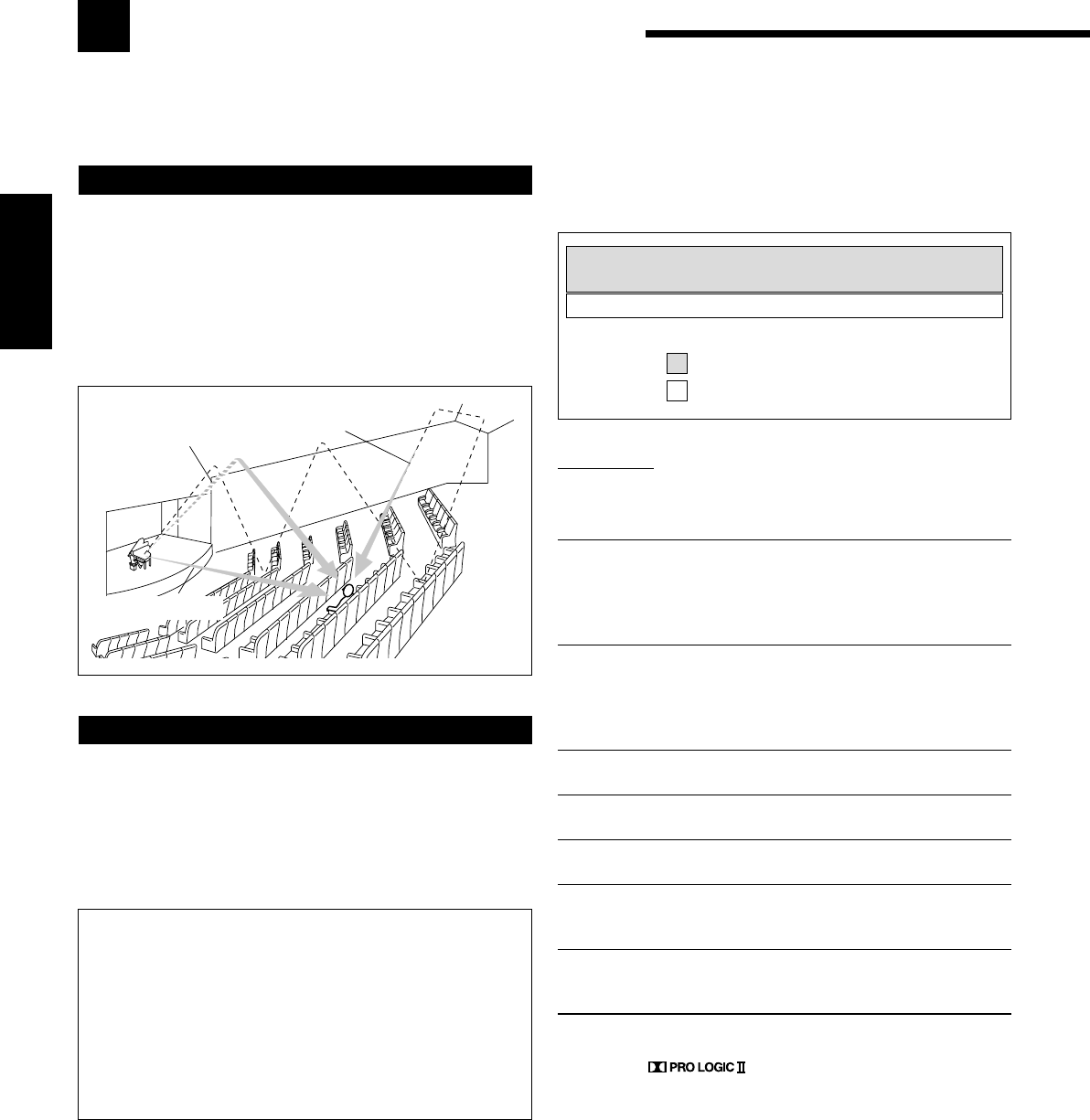
38
Français
: Pour les sources audio
: Pour les sources vidéo
Utilisation des modes DSP
Cet appareil permet de mettre en service une variété de modes DSP automatiquement. Les réglages de base et les
ajustements mémorisés (voir pages 25 à 33) sont appliqués.
Réflexions
premières
Réflexions arrière
Sons directs
Reproduction du champ sonore
Le son entendu dans une salle de concert, un club, etc. est constitué
de son direct et de son indirect—réflexions premières et réflexions
arrière. Les sons directs atteignent directement l’auditeur sans
réflexion. Inversement, les sons indirects sont retardés par la
distance des murs et des plafonds. Ces sons directs et indirects sont
les éléments les plus importants des effets acoustiques Surround.
Les modes DSP peuvent créer ces éléments importants et vous
donner une réelle impression “d’y être”.
Introduction des modes DSP
Les modes DSP comprennent les modes suivants—
•Modes DAP (Processeur acoustique numérique) (HALL 1,
HALL 2, LIVE CLUB, DANCE CLUB, PAVILION, THEATER
1, THEATER 2)
•ALL CH STEREO
•MONO FILM
Pour utiliser les modes DSP, appuyez sur DSP de façon que le
mode DSP change comme suit.
L’indicateur DSP s’allume aussi sur l’affichage.
=
HALL 1 =
HALL 2 =
LIVE CLUB
=
DANCE CLUB =
PAVILION =
ALL STEREO
= THEATER 1 =
THEATER 2 =
MONO FILM
=
(retour au début)
Modes DAP
Vous pouvez utiliser les modes DAP suivant afin de reproduire un
champ sonore plus acoustique dans votre pièce d’écoute.
HALL 1: Reproduit la sensation spatiale d’une grande
salle de concert en forme de boîte à chaussure
conçue principalement pour les concerts
classiques. (Sa capacité en siège est d’environ
2000.)
HALL 2: Reproduit la sensation spatiale d’une grande
salle de concert en forme de champ de vigne
conçue principalement pour les concerts
classiques. (Sa capacité en siège est d’environ
2000.)
LIVE CLUB: Reproduit la sensation spatiale d’un club à
concert à plafonds bas.
DANCE CLUB: Reproduit la sensation spatiale d’un club de
danse rock.
PAVILION: Reproduit la sensation spatiale d’une salle
d’exposition à haut plafond.
THEATER 1*:Reproduit la sensation spatiale d’un grand
cinéma dont la capacité en siège est d’environ
600 places.
THEATER 2*:Reproduit la sensation spatiale d’un petit cinéma
dont la capacité en siège est d’environ 300
places.
*
Le décodeur Dolby Pro Logic II intégré est mis en service lors de la
lecture des sources analogiques ou numériques à 2 canaux.
l’indicateur s’allume.
Lors de l’utilisation du mode DAP, les sons sortent de toutes les
enceintes connectées et en service.
•Si les enceintes Surround et l’enceinte centrale sont réglées sur
“NONE” dans le réglage des enceintes, le mode 3D-PHONIC
original de JVC (qui a été mis au point pour créer un effet
Surround uniquement à partir des enceintes avant) est utilisé.
L’indicateur 3D-PHONIC s’allume sur l’affichage.
Mode 3D HEADPHONE
Vous pouvez également profiter de l’effet DSP (sauf avec le
mode All Channel Stereo) avec un casque d’écoute.
Si vous appuyez sur DSP quand les enceintes avant 1 et 2 sont
toutes les deux hors service, le mode 3D HEADPHONE est mis
en service quel que soit le type de support reproduit.
“3D H PHONE” apparaît sur l’affichage et les indicateurs DSP
et HEADPHONE s’allument également.
FR34-40_8030&7030[C]f.pm6 03.2.12, 6:02 PM38
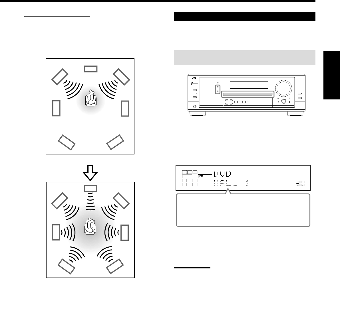
39
Français
VOLUME
LINEAR PCM
DIGITAL
L
SUBWFR
LS RS
CR
DIGITAL AUTO
DSP
SPEAKERS 1
Mode ALL Channel Stereo
Ce mode peut reproduire un champ sonore stéréo très large en
utilisant toutes les enceintes connectées (et en service). Ce mode ne
peut pas être utilisé sans enceintes Surround en service.
•Si les enceintes avant sont hors service, “All Channel Stereo” ne
peut pas être choisi.
Film monaural
Afin de reproduire un champ sonore plus acoustique dans votre
pièce d’écoute lors de la visualisation d’un support vidéo avec un
son monaural (signaux analogiques et numériques à 2 canaux), vous
pouvez utiliser ce mode.
L’effet Surround est ajouté et la localisation sonore de l’acteur est
améliorée. Ce mode ne peut pas être utilisé pour les signaux
multi-canaux numériques.
Quand “MONO FILM” est utilisé, les sons sortent de toutes les
enceintes connectées (et en service).
•Si les signaux entrant passe du signal numérique à 2 canaux sur un
autre type de signal numérique, “MONO FILM” est annulé et le
mode Surround approprié est mis en service.
Mise en service du mode DSP
Mettre en service un des modes DSP pour une source rappelle
automatiquement les réglages et les ajustements mémorisés.
(Voir pages 25 à 33.)
Vous pouvez aussi utiliser les touches sur la télécommande pour
les mêmes fonctions.
1. Choisissez et reproduisez une source.
2. Appuyez répétitivement sur DSP jusqu’à ce que
le mode DSP souhaité apparaisse sur l’affichage.
•Chaque fois que vous appuyez sur la touche, le mode DSP
change comme suit:
=
HALL 1 =
HALL 2 =
LIVE CLUB
=
DANCE CLUB =
PAVILION =
ALL STEREO*
= THEATER 1 =
THEATER 2 =
MONO FILM**
=
(retour au début)
*
Quand les enceintes Surround sont réglées sur “NONE”, vous
ne pouvez pas choisir “ALL STEREO”.
**
Quand des signaux multi-canaux entrent dans l’appareil, vous
ne pouvez pas choisir “MONO FILM”.
Remarque:
Quand les enceintes Surround sont mises hors service, le traitement
3D-PHONIC est appliqué au mode DSP (l’indicateur 3D-PHONIC
s’allume aussi).
Pour annuler le mode DSP
Appuyez sur SURROUND/DSP OFF (ou sur SURR/DSP OFF sur la
télécommande). “SURR OFF” apparaît sur l’affichage.
•Quand les enceintes avant sont mises hors service,
“HEADPHONE” apparaît.
Son reproduit avec le mode stéréo normal
Son reproduit avec le mode All Channel Stereo
FR34-40_8030&7030[C]f.pm6 03.2.12, 6:02 PM39
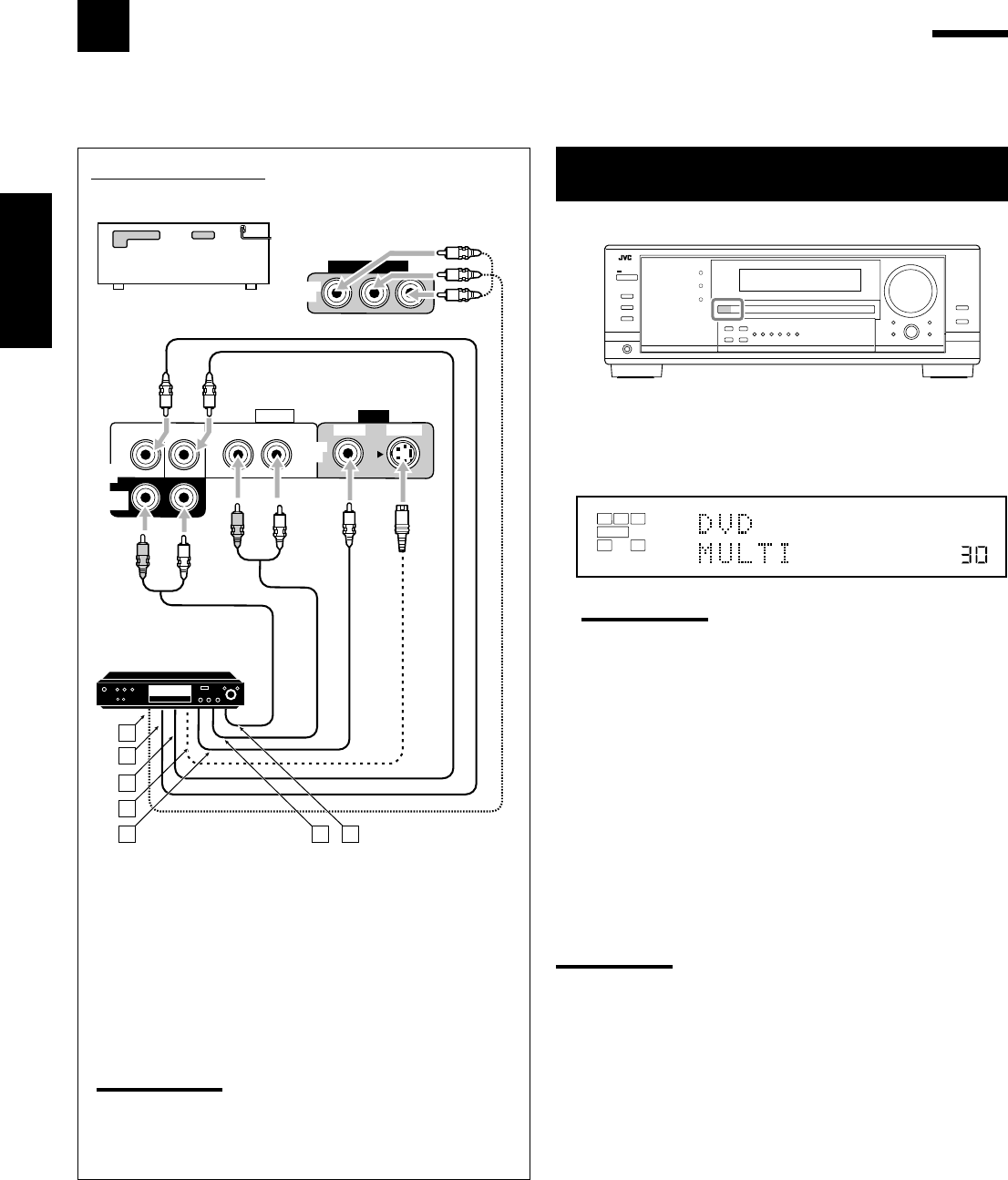
40
Français
Utilisation du mode de lecture DVD MULTI
Cet ampli-tuner possède un mode de lecture DVD MULTI permettant de reproduire le mode de sortie analogique
discret du lecteur de DVD.
Mise en service du mode de lecture DVD
MULTI
1. Appuyez sur DVD MULTI de façon que “DVD
MULTI” apparaisse sur l’affichage.
L’indicateur MULTI s’allume aussi.
Remarque:
Quand vous choisissez “DVD MULTI” comme source de lecture,
les modes Surround et DSP sont annulés et les touches
SURROUND et DSP ne fonctionnent pas.
2. Choisissez le mode de sortie analogique discret sur
le lecteur de DVD et démarrer la lecture d’un DVD.
•Référez-vous aussi au mode d’emploi fourni avec le lecteur de
DVD.
Vous pouvez ajuster les courbes d’égalisation numérique et le
niveau de sortie des enceintes. Référez-vous à “Ajustement des
courbes d’égalisation” à la page 32 pour les détails.
Remarques:
•Le mode de minuit n’est pas disponible pour le mode de lecture
DVD MULTI (voir page 20).
•Lors de l’utilisation d’un casque d’écoute, vous pouvez écouter
uniquement les canaux avant (gauche et droit).
Schéma de connexion
DVD
VIDEO
RIGHT LEFT
S-VIDEO
VIDEO
AUDIO
SUBWOOFER CENTER
DVD
IN
FRONT
DVD
IN
COMPONENT VIDEO
DVD
IN
SURR
(REAR)
RL
RL
A
B
C
D
E F G
RX-8030VBK/RX-7030VBK
ÅÀ la sortie en composantes vidéo
ıÀ la sortie du caisson de grave
ÇÀ la sortie audio du canal central
ÎÀ la sortie S-vidéo
‰À la sortie vidéo composite
ÏÀ la sortie audio du canal avant gauche/droit
ÌÀ la sortie audio du canal Surround gauche/droit
Remarque:
Lors de la connexion d’un lecteur de DV aux prises d’entrée en
composantes vidéo, réglez l’entrée en composantes vidéo
correctement. Référez-vous à la page 30 pour les détails.
VOLUME
LINEAR PCM
L
SUBWFR
LS RS
CR
ANALOG MULTI
SPEAKERS 1
Lecteur de DVD
FR34-40_8030&7030[C]f.pm6 03.2.12, 6:02 PM40
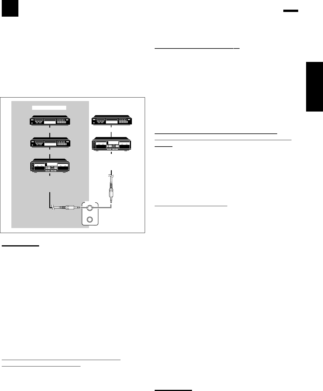
41
COMPU LINK-4
(SYNCHRO)
Lecteur CD
Enregistreur de CD
Platine cassette
ou
enregistreur de MD
Platine cassette
ou
enregistreur de CD
Lecteur CD
RX-7030VBK
RX-8030VBK
Français
Pour utiliser ce système de commande à distance, vous devez
connecter les appareils audio JVC à l’aide des prises COMPU LINK
(SYNCHRO) (voir ci-dessous) en plus des connexions utilisant les
câbles munis de fiches cinch (voir pages 12 et 13).
•Assurez-vous que les cordons d’alimentation secteur de ces
appareils sont débranchés avant de réaliser la connexion. Branchez
les cordons d’alimentation secteur uniquement après que toutes les
connexions sont terminées.
Remarques:
•Il y a quatre versions du système de commande à distance
COMPU LINK. Cet ampli-tuner est équipé de la quatrième version
—COMPU LINK-4. Par rapport aux versions précédentes, cette
version possède en plus des opérations systématiques avec les
enregistreurs de CD—COMPU LINK-3.
•Si votre appareil audio possède deux prises jacks COMPU LINK,
vous pouvez utiliser n’importe laquelle. S’il ne possède qu’une prise
jack COMPU LINK, connectez-le de façon qu’il soit le dernier
élément de la série d’appareils.
•Pour commander l’appareil cible en utilisant le système de
commande à distance COMPU LINK, réglez correctement, si
nécessaire, le nom de la source. (Voir page 21.)
•Référez-vous aussi aux modes d’emploi fournis avec vos appareils
audio.
Ce système de commande à distance vous permet d’utiliser les
quatre fonctions décrites ci-dessous.
Commande à distance à travers le capteur de
télécommande de l’ampli-tuner
Vous pouvez commande les appareils audio connectés à travers le
capteur de télécommande de cet ampli-tuner en utilisant cette
télécommande. Dirigez la télécommande directement sur le capteur
de télécommande de cet ampli-tuner. Pour plus de détails, référez-
vous aux pages 44 et 45.
Système de commande à distance COMPU LINK
Le système de commande à distance COMPU LINK vous permet de commander les appareils audio JVC à travers
l’ampli-tuner.
Sélection automatique de source
Quand vous appuyez sur la touche de lecture (33
33
3) sur un appareil
connecté ou sur sa télécommande, l’ampli-tuner se met
automatiquement sous tension et change la source sur l’appareil.
Inversement, si vous choisissez une nouvelle source sur l’ampli-
tuner ou sur sa télécommande, l’appareil choisi démarre la lecture
immédiatement.
Dans les deux cas, la source précédemment choisie continue d’être
reproduite sans son pendant quelques secondes.
•Pour le RX-7030VBK: Vous ne pouvez pas utiliser le système de
commande à distance COMPU LINK pour commander
l’enregistreur de MD.
Mise sous/hors tension (attente) automatique:
possible uniquement avec COMPU LINK-3 et COMPU
LINK-4
Les appareils connectés se mettent sous et hors tension (attente) en
même temps que l’ampli-tuner.
Quand vous mettez l’ampli-tuner sous tension, un des appareils
connectés se met automatiquement sous tension, l’appareil qui a été
choisi en dernier.
Quand vous mettez hors tension l’ampli-tuner, les appareils
connectés se mettent hors tension (attente).
Enregistrement synchronisé
L’enregistrement synchronisé signifie que la platine cassette (ou
l’enregistreur de MD) démarre l’enregistrement dès que la lecture
du CD commence.
Pour utiliser l’enregistrement synchronisé, suivez ces étapes:
1. Mettez une cassette dans la platine cassette (ou
un MD dans l’enregistreur de MD) et un disque
dans le lecteur CD.
2. Appuyez en même temps sur la touche
d’enregistrement (¶) et sur la touche de pause (8)
sur la platine cassette (ou l’enregistreur de MD).
La platine cassette (ou l’enregistreur de MD) est mise en mode
de pause à l’enregistrement.
Si vous n’appuyez en même temps pas sur la touche
d’enregistrement (¶) et la touche de pause (8), l’enregistrement
synchronisé ne fonctionne pas.
3. Appuyez sur la touche de lecture (3) sur le
lecteur CD.
La source change sur l’ampli-tuner et aussitôt que la lecture
commence, la platine cassette (ou l’enregistreur de MD)
démarre l’enregistrement. Quand la lecture est terminée, la
platine cassette (ou l’enregistreur de MD) entre en mode de
pause à l’enregistrement, et s’arrête environ 4 secondes plus
tard.
Remarques:
•Pendant l’enregistrement synchronisé, la source choisie ne peut
pas être changée.
•Si l’alimentation d’un des appareils est coupée pendant
l’enregistrement synchronisé, le système de commande à distance
COMPU LINK peut ne pas fonctionner correctement. Dans ce cas,
vous devez recommencer du début.
FR41_41_8030&7030[C]f.pm6 03.2.12, 6:03 PM41
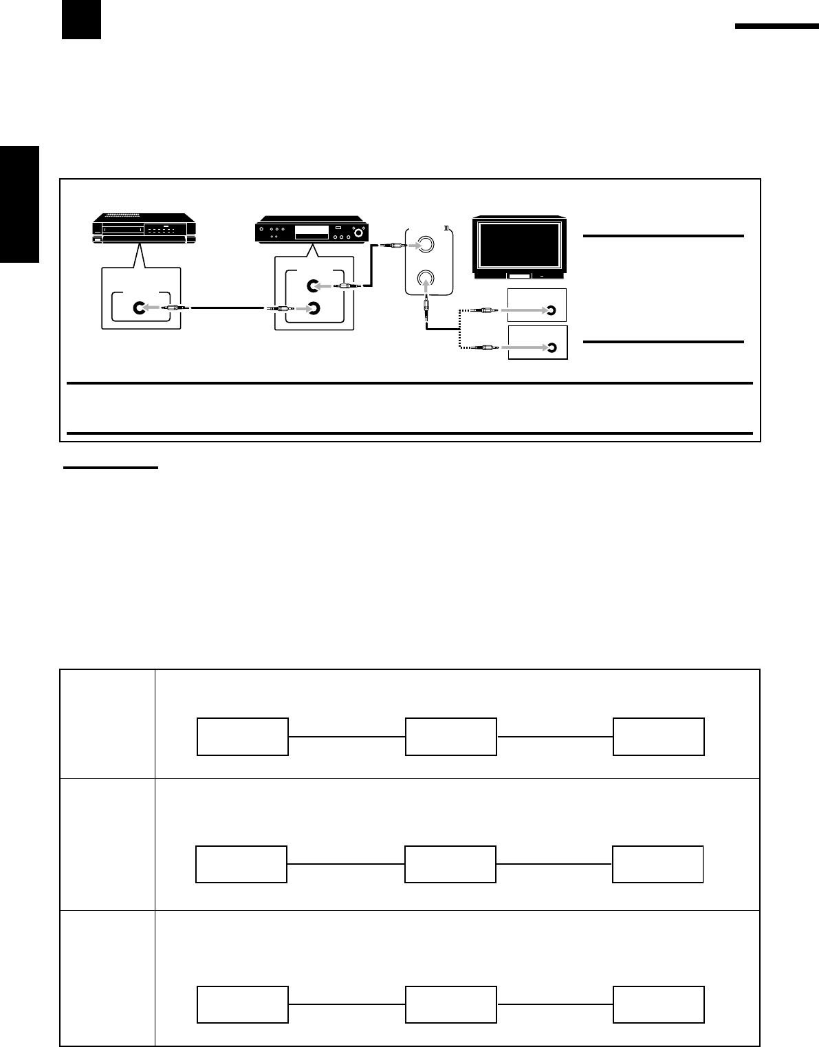
42
Français
CAS 1 Lors de la connexion de l’appareil source à l’ampli-tuner en utilisant les prises S-vidéo, connectez aussi
cet ampli-tuner à la prise d’entrée vidéo 1 du téléviseur en utilisant des câbles S-vidéo.
Lors de la connexion de l’appareil source à l’ampli-tuner en utilisant les prises vidéo composites,
connecter aussi cet ampli-tuner aux prises d’entrée vidéo 2 du téléviseur (entrée vidéo composites) en
utilisant des câbles vidéo composites.
Lors de la connexion de l’appareil source à l’ampli-tuner en utilisant les prises en composantes vidéo,
connecter aussi cet ampli-tuner aux prises d’entrée vidéo 2 du téléviseur (entrée en composantes vidéo)
en utilisant des câbles en composantes vidéo.
Appareil
source RX-8030VBK
RX-7030VBK Téléviseur
À l’entrée vidéo 1
Câble S-vidéo
Câble S-vidéo
Appareil
source RX-8030VBK
RX-7030VBK Téléviseur
À l’entrée vidéo 2
Câble vidéo
composite
Câble vidéo
composite
Appareil
source RX-8030VBK
RX-7030VBK Téléviseur
À l’entrée vidéo 2
Câble en
composantes vidéo
Câble en
composantes vidéo
AV
COMPULINK-
AV
COMPU LINK
VHS
AV
COMPU LINK AV
COMPU LINK EX
DVD
AV
COMPU LINK-
ΙΙΙ
CONNEXIONS 2: Connexion des câbles vidéo
Cet ampli-tuner est muni de trois types de prises vidéo—S-vidéo, vidéo composite et en composantes vidéo, et les signaux entrant dans cet
ampli-tuner par un type de prise vidéo ne peuvent être sortis que par le même type de prise. Il faut donc connecter le magnétoscope et/ou le
lecteur de DVD au téléviseur en utilisant une des trois méthodes suivantes:
•Lors de l’utilisation du système de commande à distance AV COMPU LINK, réglez correctement l’entrée en composantes vidéo
pour le lecteur de DVD et le tuner DBS (référez-vous à “Réglage de l’entrée en composantes vidéo” à la page 30); sinon, l’entrée
correcte pour cet ampli-tuner n’est pas choisie sur le téléviseur.
Remarques:
•Lors de la connexion de l’ampli-tuner et d’un téléviseur avec une prise AV COMPU LINK EX en utilisant un câble en composantes vidéo, il
n’est pas possible d’utiliser la sélection automatique du mode d’entrée du téléviseur (voir page 43).
•Lorsque l’on connecte uniquement le magnétoscope et le lecteur de DVD à cet ampli-tuner, les connecter directement à l’ampli-tuner en
utilisant un câble avec mini fiches monaurales.
Système de commande à distance AV COMPU LINK
Le système de commande à distance AV COMPU LINK vous permet de commander les appareils vidéo JVC (téléviseur,
magnétoscope et lecteur de DVD) à travers cet ampli-tuner.
Cet ampli-tuner est muni du système AV COMPU LINK-III, qui possède une fonction supplémentaire pour commander les appareils vidéo
JVC par les prises en composantes vidéo. Pour utiliser ce système de commande à distance, vous devez connecter les appareils vidéo que
vous souhaitez commander en suivant les illustrations ci-dessous et la procédure de la page suivante.
ATTENTION:
Il est seulement possible de
connecter un téléviseur avec une
prise AV COMPU LINK EX ou
AV COMPU LINK-III. NE
connectez PAS l’ampli-tuner à
un téléviseur avec une prise AV
COMPU LINK RECEIVER/AMP.
Téléviseur
Lecteur de DVD
Magnétoscope
IMPORTANT:
Le système de commande à distance AV COMPU LINK ne peut pas commander le tuner DBS.
•Pour le RX-8030VBK: Connectez le magnétoscope aux prises VCR1. L’appareil vidéo connecté aux prises VIDEO et VCR 2 sur l’ampli-
tuner ne peut pas être commandé avec le système de commande à distance AV COMPU LINK.
CONNEXIONS 1: Connexion AV COMPU LINK
CAS 2
CAS 3
FR42-52_8030&7030[C]f.pm6 03.2.12, 6:03 PM42

43
Français
1. Si vous avez déjà branché votre magnétoscope, le
lecteur de DVD, le téléviseur et cet ampli-tuner
sur une prise secteur, débranchez d’abord leurs
cordons d’alimentation.
2. Connectez votre magnétoscope, le lecteur de
DVD, le téléviseur et cet ampli-tuner en utilisant
des câbles avec mini fiches monaurales (non
fournis).
•Référez-vous à “CONNEXIONS 1”, à la page précédente.
3. Connectez les prises d’entrée/sortie audio du
magnétoscope, du lecteur de DVD, du téléviseur
et de cet ampli-tuner en utilisant des câbles à
fiches cinch.
•Référez-vous aux pages 14 et 15.
4. Connectez les prises d’entrée/sortie vidéo du
magnétoscope, du lecteur de DVD, du téléviseur
et de cet ampli-tuner en utilisant des câbles à
fiches cinch, S-vidéo ou en composantes vidéo.
•Référez-vous à “CONNEXIONS 2”, à la page précédente.
5. Branchez les cordons d’alimentation des
appareils et de cet ampli-tuner dans les prises
secteurs.
6. Quand le téléviseur est mis sous tension pour la
première fois après la connexion AV COMPU
LINK, réglez le volume du téléviseur au
minimum en utilisant le réglage du volume du
téléviseur.
7. Mettez d’abord les appareils connectés sous
tension, puis cet ampli-tuner.
•Pour mettre sous tension le magnétoscope, utilisez la
télécommande fournie avec cet ampli-tuner.
Le système de commande à distance AV COMPU LINK vous
permet d’utiliser les cinq fonctions de base décrites ci-dessous.
Commande à distance du téléviseur, lecteur de DVD et
magnétoscope en utilisant cette télécommande
Référez-vous à la page 46 pour les détails.
•Diriger la télécommande directement sur le capteur de
télécommande de chaque appareil.
Reproduction vidéo monotouche
En insérant simplement une cassette vidéo sans sa languette de
sécurité dans le magnétoscope, il est possible de lancer la lecture
vidéo sans avoir à toucher d’autres touches.
L’ampli-tuner se met automatiquement sous tension et change la
source sur “VCR 1” (pour le RX-8030VBK) ou sur “VCR” (pour le
RX-7030VBK).
Le téléviseur se met automatiquement sous tension et change son
mode d’entrée sur la position correcte sur laquelle vous pouvez voir
le magnétoscope.
Si vous insérez une cassette avec sa languette de sécurité, appuyez
sur la touche de lecture (33
33
3) sur le magnétoscope ou sur la
télécommande pour obtenir le même résultat.
Reproduction DVD monotouche
En démarrant simplement la lecture sur le lecteur de DVD, il est
possible de voir un DVD sans avoir à appuyer sur d’autres touches.
•Quand le lecteur de DVD est connecté par les prises d’entrée
analogiques à cet ampli-tuner (et que l’entrée analogique est
choisie), l’ampli-tuner se met automatiquement sous tension et
change la source sur “DVD” ou “DVD MULTI”.
•Quand le lecteur de DVD est connecté par la prise d’entrée
numérique à cet ampli-tuner (et que l’entrée numérique est
choisie), l’ampli-tuner se met automatiquement sous tension et
change la source sur “DVD”.
Le téléviseur se met automatiquement sous tension et change son
mode d’entrée sur la position correcte sur laquelle vous pouvez voir
l’image de lecture.
Sélection automatique du mode d’entrée du téléviseur
•Quand “TV” est choisi comme source de lecture sur l’ampli-tuner,
le téléviseur change automatiquement son mode d’entrée sur son
tuner de façon que l’on puisse regarder la télévision.
•Quand une autre source vidéo que “TV” est choisie comme source
de lecture sur l’ampli-tuner, le téléviseur change automatiquement
son mode d’entrée sur la position correcte (l’entrée vidéo 1 ou
l’entrée vidéo 2) qui permet de regarder l’image de lecture.
Remarques:
•Quand “TV” est choisi comme source, il n’est pas possible de voir
les menus sur l’écran du téléviseur car le système de commande à
distance AV COMPU LINK change automatiquement le mode
d’entrée du téléviseur sur le tuner de télévision.
•Cette fonction ne peut pas être utilisée quand vous connectez cet
ampli-tuner et le téléviseur avec la prise AV COMPU LINK EX en
utilisant un câble en composantes vidéo. Dans ce cas, reconnectez
le téléviseur en vous référent au cas 1 ou au cas 2 de la page 42.
Mise sous/hors tension automatique
Le téléviseur, le magnétoscope et le lecteur de DVD se mettent
sous et hors tension en même temps que l’ampli-tuner.
Quand l’ampli-tuner est mis sous tension;
•Si la dernière source choisie est “VCR 1” (pour le RX-8030VBK)
ou “VCR” (pour le RX-7030VBK), le téléviseur et le
magnétoscope se mettent automatiquement sous tension.
•Si la dernière source choisie est “DVD” ou “DVD MULTI”, le
téléviseur et le lecteur de DVD se mettent automatiquement sous
tension.
•Si la dernière source choisie est une autre source vidéo, seul le
téléviseur se met automatiquement sous tension.
Quand l’ampli-tuner est mis hors tension, le téléviseur, le
magnétoscope et le lecteur de DVD se mettent hors tension.
Remarque:
Si l’ampli tuner est mis hors tension pendant un enregistrement sur le
magnétoscope, le magnétoscope ne se met pas hors tension mais
continue l’enregistrement.
FR42-52_8030&7030[C]f.pm6 03.2.12, 6:03 PM43
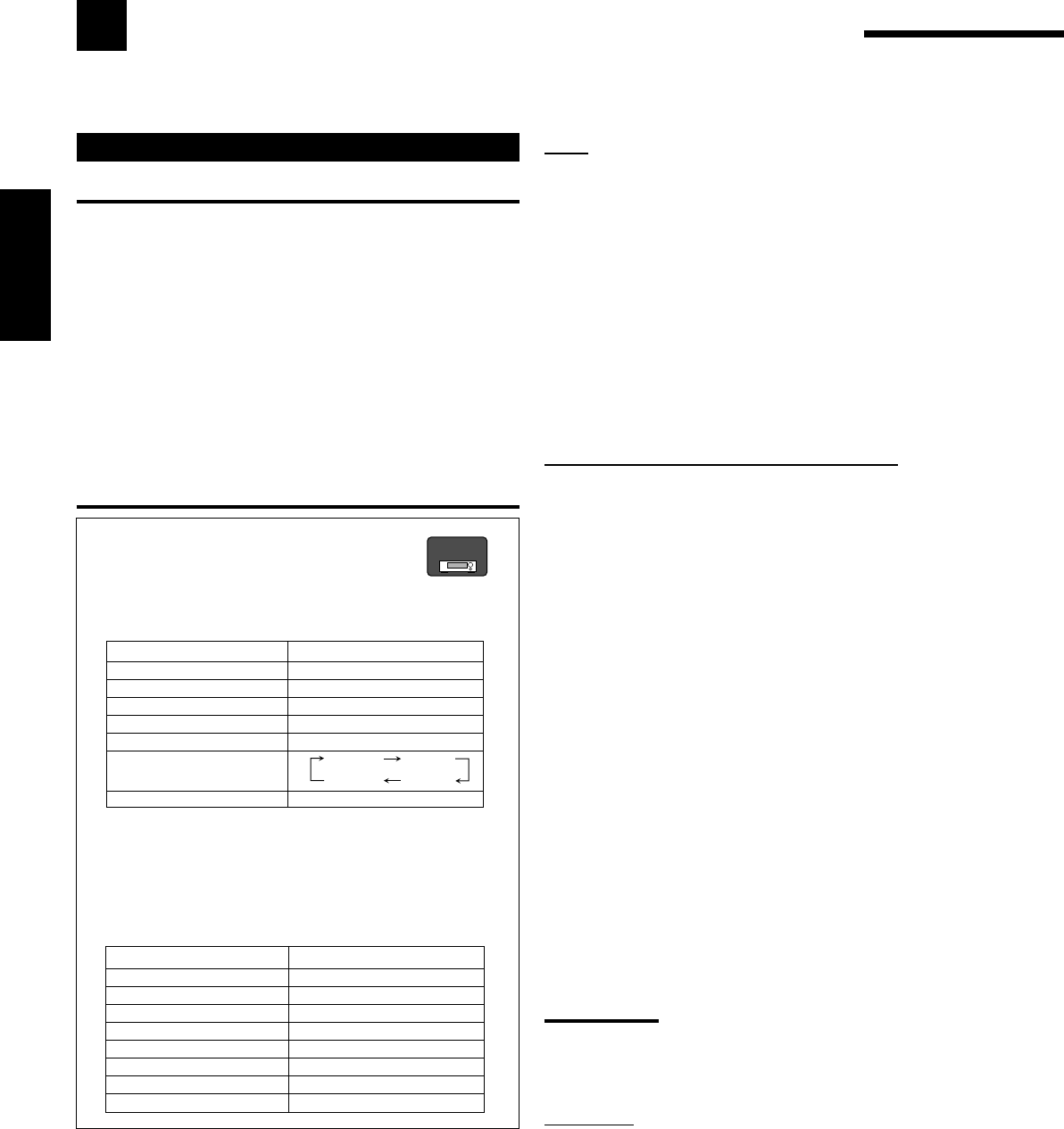
44
Français
Commande d’appareils audio
IMPORTANT:
Pour commander des appareils audio JVC en utilisant la
télécommande fournie:
•Vous devez connecter les appareils audio JVC par les prises
COMPU LINK (SYNCHRO) (voir page 41) en plus de connexions
avec les câbles munis de fiches cinch (voir pages 11 à 13).
•Dirigez la télécommande directement sur le capteur de
télécommande de l’ampli-tuner.
•Si vous utilisez les touches du panneau avant pour choisir une
source, la télécommande ne peut pas commander cette source. Pour
commander une source avec la télécommande, la source doit être
choisie avec les touches de la télécommande.
•Pour pouvoir commander l’appareil cible en utilisant le système de
commande à distance COMPU LINK, réglez le nom de la source
correctement. (Voir page 21.)
•Référez-vous aussi aux modes d’emploi fournis avec les appareils.
Pour le RX-8030VBK:
•Quand vous appuyez sur une des touches de
sélection de source, le mode de télécommande
apparaît sur la fenêtre d’affichage pendant
environ deux heures.
Touches Indications
FM/AM TUNER
CD CD
CDR CDR
PHONO PHONO
TAPE/MD TAPE
CONTROL (répétitivement)*
SOUND SOUND
*
En appuyant répétitivement sur CONTROL, vous pouvez
choisir “VCR 1”, “TAPE”, “CDR” ou “CDDSC” comme source.
•Quand vous appuyez sur une des touches suivantes, le mode
de télécommande apparaît sur la fenêtre d’affichage pendant
environ deux heures.
Touches Indications
FRONT•L FRL
FRONT•R FRR
CENTER CTR
SURR•L SURRL
SURR•R SURRR
SURR BACK SBK
SUBWOOFER S-WFR
DIGITAL EQ EQ
Commande d’appareils audio/vidéo JVC
Vous pouvez commander des appareils audio et vidéo JVC avec la télécommande de cet ampli-tuner car les signaux de
commande des appareils JVC sont préréglés dans la télécommande.
Tuner
Vous pouvez toujours réaliser les opérations suivantes:
FM/AM: Alterner entre FM et AM.
Après avoir appuyé sur FM/AM, vous pouvez réaliser les opérations
suivantes sur un tuner:
1 – 10/0, +10: Choisir un numéro de canal directement.
Pour le numéro de canal 5, appuyez sur 5.
Pour le numéro de canal 15, appuyez sur +10, puis
sur 5.
Pour le numéro de canal 20, appuyez sur +10, puis
sur 10/0.
TUNING UP/DOWN:
Accorder une station.
FM MODE: Changer le mode de réception FM.
Section de commande du son (Amplificateur)
Vous pouvez toujours réaliser les opérations suivantes:
SURROUND: Mettre en service et choisir un mode Surround.
DSP: Mettre en service et choisir un mode DSP.
SURR/DSP OFF: Metter hors service les modes Surround et DSP.
Après avoir appuyé sur SOUND, vous pouvez réaliser les opérations
suivantes:
FRONT•L puis LEVEL +/–:Ajuster le niveau de sortie de
l’enceinte avant gauche.
FRONT•R puis LEVEL +/–:Ajuster le niveau de sortie de
l’enceinte avant droite.
CENTER puis LEVEL +/–: Ajuster le niveau de sortie de
l’enceinte centrale.
SURR•L puis LEVEL +/–: Ajuster le niveau de sortie de
l’enceinte Surround gauche.
SURR•R puis LEVEL +/–: Ajuster le niveau de sortie de
l’enceinte Surround droite.
SURR BACK: Ajuster le niveau de sortie de
l’enceinte Surround arrière.
SUBWOOFER puis LEVEL +/–:
Ajuster le niveau de sortie du
caisson de grave.
DIGITAL EQ puis LEVEL+/–: Choisir la bande de fréquence et
ajuster son niveau.
TEST: Mettre en ou hors service la sortie
de la tonalité de test.
BASS BOOST: Mettre en ou hors service
l’accentuation des graves.
Remarque:
Après avoir ajusté le son, appuyez sur la touche de sélection de source
correspondante pour commander la source souhaitée en utilisant les
touches numériques. Sinon, les touches numériques ne peuvent pas
être utilisées pour commander la source souhaitée.
Lecteur CD
Après avoir appuyé sur CD, vous pouvez réaliser les opérations
suivantes sur un lecteur CD:
3:Démarer la lecture.
4:Retourner au début de la plage actuelle (ou précédente).
¢: Sauter au début de la plage suivante.
7:Arrêter la lecture.
8:Arrêter la lecture momentanément. Pour reprendre,
appuyez sur 3.
1 – 10/0, +10:
Choisir un numéro de plage directement.
Pour la plage numéro 5, appuyez sur 5.
Pour la plage numéro 15, appuyez sur +10, puis sur 5.
Pour la plage numéro 20, appuyez sur +10, puis sur 10/0.
Pour la plage numéro 30, appuyez sur +10, sur +10, puis
sur 10/0.
RX-8030V
ONLY
VCR 1 TAPE
CDR
CDDSC
FR42-52_8030&7030[C]f.pm6 03.2.12, 6:03 PM44
45
Français
Changeur de CD
Pour le RX-8030VBK:
Après avoir choisi “CDDSC” en appuyant répétitivement sur
CONTROL, vous pouvez réaliser les opérations suivantes sur un
changeur de CD:
Pour le RX-7030VBK:
Après avoir appuyé sur CD DISC, vous pouvez réaliser les
opérations suivantes sur un changeur de CD:
3:Démarer la lecture.
4:Retourner au début de la plage actuelle (ou
précédente).
¢: Sauter au début de la plage suivante.
7:Arrêter la lecture.
8:Arrêter la lecture momentanément. Pour reprendre,
appuyez sur 3.
1 – 6, 7/P: Choisir le numéro d’un disque en place dans le
changeur de CD.
Après avoir appuyé sur CD, vous pouvez réaliser les opérations
suivantes sur un changeur de CD:
1 – 10/0, +10: Choisir un numéro de plage directement.
Pour la plage numéro 5, appuyez sur 5.
Pour la plage numéro 15, appuyez sur +10, puis sur 5.
Pour la plage numéro 20, appuyez sur +10,
puis sur 10/0.
Pour la plage numéro 30, appuyez sur +10, sur +10,
puis sur 10/0.
Exemple:
•Sélection du disque numéro 4, plage numéro 12 et démarrage de la
lecture.
Pour le RX-8030VBK:
1. Appuyez répétitivement sur CONTROL jusqu’à ce que
“CDDSC” apparaisse sur la fenêtre d’affichage, puis
appuyer sur 4.
2. Appuyez sur CD, puis sur +10, 2.
Pour le RX-7030VBK:
1. Appuyez sur CD DISC, puis sur 4.
2. Appuyez sur CD, puis sur +10, 2.
Si le changeur de CD à une capacité de 200 disques (sauf pour le
XL-MC100 et XL-MC301)
Il est possible de réaliser les opérations suivantes à l’aide des
touches numériques après avoir appuyé sur CD.
1. Choisissez un numéro de disque.
2. Choisissez ensuite un numéro de plage (entrer toujours 2 chiffres).
3. Démarrez la lecture.
Exemples:
•Sélection du disque numéro 3, plage numéro 2 et démarrage de la
lecture.
Appuyez sur 3, sur 0 et 2, puis sur 3.
•Sélection du disque numéro 10, plage numéro 5 et démarrage de la
lecture.
Appuyez sur 1 et 0, sur 0 et 5, puis sur 3.
•Sélection du numéro de disque 105, plage numéro 12, et
démarrage de la lecture.
Appuyez sur 1, 0 et 5, sur 1 et 2, puis sur 3.
Tourne-disque
Après avoir appuyé sur PHONO, vous pouvez réaliser
les opérations suivantes sur un tourne-disque:
3:Démarrer la lecture.
7:Arrêter la lecture.
Enregistreur de CD
Pour le RX-8030VBK: Après avoir appuyé sur CDR (ou choisi
“CDR” en appuyant répétitivement sur CONTROL), vous pouvez
réaliser les opérations suivantes sur un enregistreur de CD:
Pour le RX-7030VBK: Après avoir appuyé sur TAPE/CDR (ou
TAPE/CDR CONTROL), vous pouvez réaliser les opérations
suivantes sur un enregistreur de CD:
3:Démarer la lecture.
4:Retourner au début de la plage actuelle (ou
précédente).
¢: Sauter au début de la plage suivante.
7:Arrêter la lecture.
8:Arrêter la lecture momentanément. Pour reprendre,
appuyez sur 3.
1 – 10/0, +10: Choisir un numéro de plage directement.
Pour la plage numéro 5, appuyez sur 5.
Pour la plage numéro 15, appuyez sur +10, puis sur 5.
Pour la plage numéro 20, appuyez sur +10,
puis sur 10/0.
Pour la plage numéro 30, appuyez sur +10, sur +10,
puis sur 10/0.
REC PAUSE: Entrer en mode de pause à l’enregistrement en
appuyant sur cette touche.
Pour reprendre l’enregistrement, appuyez sur cette
touche plus sur 3.
Platine cassette
Pour le RX-8030VBK: Après avoir appuyé sur TAPE/MD (ou
choisi “TAPE” en appuyant répétitivement sur CONTROL), vous
pouvez réaliser les opérations suivantes sur une platine cassette:
Pour le RX-7030VBK: Après avoir appuyé sur TAPE/CDR (ou
TAPE/CDR CONTROL), vous pouvez réaliser les opérations
suivantes sur une platine cassette:
3:Démarre la lecture.
REW: Avancer rapidement la bande de la droite vers la
gauche.
FF: Avancer rapidement la bande de la gauche vers la
droite.
7:Arrêter la lecture ou l’enregistrement.
8:Arrêter la lecture momentanément. Pour reprendre,
appuyez sur 3.
REC PAUSE: Entrer en mode de pause à l’enregistrement en
appuyant sur cette touche.
Pour reprendre l’enregistrement, appuyez sur cette
touche plus sur 3.
Enregistreur de MD
Après avoir appuyé sur TAPE/MD (ou choisi “TAPE*” en
appuyant répétitivement sur CONTROL), vous pouvez réaliser les
opérations suivantes sur un enregistreur de MD:
3:Démarer la lecture.
4:Retourner au début de la plage actuelle (ou
précédente).
¢: Sauter au début de la plage suivante.
7:Arrêter la lecture.
8:Arrêter la lecture momentanément. Pour reprendre,
appuyez sur 3.
REC PAUSE: Entrer en mode de pause à l’enregistrement en
appuyant sur cette touche.
Pour reprendre l’enregistrement, appuyez sur cette
touche plus sur 3.
*
Choisir “TAPE” vous permet de commander l’enregistreur de MD.
RX-8030V
ONLY
Remarque:
Vous pouvez utiliser les touches de sélection de source ou la touche de commande (CONTROL pour le RX-8030VBK ou TAPE/CDR
CONTROL pour le RX-7030VBK) pour activer les touches pour l’appareil source. Si vous appuyez sur une des touches de sélection de
source, la source de lecture change aussi. Par contre, appuyer sur une touche de commande ne change pas la source de lecture.
RX-8030V
ONLY
FR42-52_8030&7030[C]f.pm6 03.2.12, 6:03 PM45
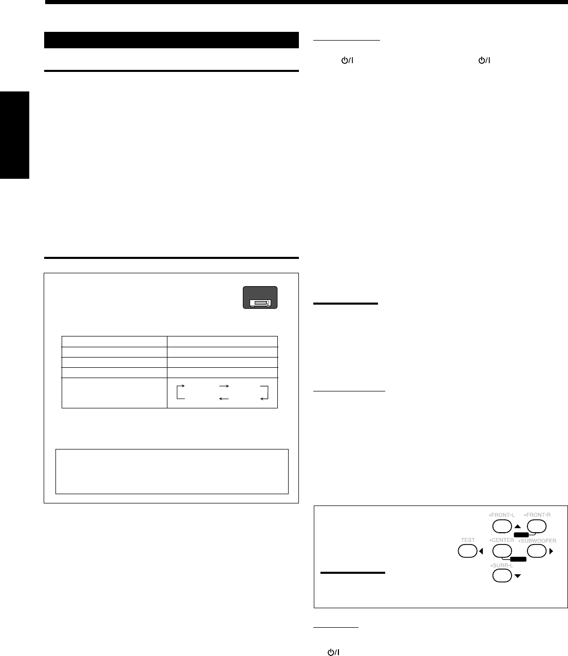
46
Français
Magnétoscope
Vous pouvez toujours réaliser les opérations suivantes:
VCR 1 (pour le RX-8030VBK) ou VCR (pour le RX-
7030VBK) : Mettre sous ou hors tension le magnétoscope.
Pour le RX-8030VBK: Après avoir appuyé sur VCR 1 (ou choisi
“VCR 1” en appuyant répétitivement sur CONTROL), vous pouvez
réaliser les opérations suivantes sur un magnétoscope:
Pour le RX-7030VBK: Après avoir appuyé sur VCR (ou VCR
CONTROL), vous pouvez réaliser les opérations suivantes sur un
magnétoscope:
1 – 9, 0: Choisir les canaux de téléviseur sur le magnétoscope.
3:Démarrer la lecture.
REW: Rebobiner la bande.
FF: Avancer rapidement la bande.
7:Arrêter la lecture ou l’enregistrement.
8:Arrêter momentanément la lecture. Pour reprendre,
appuyez sur 3.
REC PAUSE: Entrer en mode de pause à l’enregistrement en
appuyant sur cette touche.
Pour reprendre l’enregistrement, appuyez sur cette
touche plus sur 3.
CH +/–:Changer les canaux de téléviseur sur le magnétoscope.
Remarque:
Il est possible d’utiliser VCR1 (pour le RX-8030VBK) ou VCR (pour le
RX-7030VBK) ou la touche de commande (CONTROL pour le RX-
8030VBK ou VCR CONTROL pour le RX-7030VBK) pour activer les
touches décrites ci-dessus. Si vous appuyez sur une des touches de
sélection de source, la source de lecture change aussi. Par contre, si
vous appuyez sur la touche de commande, la source de lecture ne
change pas.
Lecteur de DVD
Après avoir appuyé sur DVD ou sur DVD MULTI, vous pouvez
réaliser les opérations suivantes sur un lecteur de DVD:
3:Démarrer la lecture.
4:Retourner au début du chapitre actuel (ou précédent).
¢:Sauter au début du chapitre suivant.
7:Arrêter la lecture.
8:Arrêter momentanément la lecture. Pour reprendre, appuyez
sur 3.
Après avoir appuyé sur DVD ou
DVD MULTI, ces touches peuvent
être utilisées pour commander le
menu de DVD.
Remarque:
Pour les opérations détaillées
concernant le menu DVD, se référer aux instructions fournies avec
les disques ou le lecteur de DVD.
Téléviseur
Vous pouvez toujours réaliser les opérations suivantes:
TV : Mettre sous ou hors tension le téléviseur.
TV VOL +/–: Ajuster le volume.
TV/VIDEO:Régler le mode d’entrée (TV ou VIDEO).
Après avoir appuyé sur TV/DBS, vous pouvez réaliser les
opérations suivantes sur un téléviseur:
CH +/–:Changer les canaux.
1 – 9, 0, 100+: Choisir les canaux.
RETURN: Alterner entre le canal choisi précédemment et le
canal actuel.
Commande d’appareils vidéo
IMPORTANT:
Pour commander des appareils vidéo JVC en utilisant cette
télécommande:
•Vous devez connecter les appareils vidéo JVC à l’aide des prises
AV COMPU LINK (voir page 42) en plus des connexions
utilisant les câbles à fiches cinch (voir pages 14 et 15).
•Certains magnétoscopes JVC peuvent recevoir deux types de
signaux de commande—code de télécommande “A” et “B”.
Avant d’utiliser cette télécommande, s’assurer que le code de
télécommande du magnétoscope cible est réglé sur le code “A”.
–For RX-8030VBK: Quand un autre magnétoscope JVC est
connecté aux prises VCR 2 ou VIDEO, régler son code de
télécommande sur “B”. (Cette télécommande ne peut pas
émettre les signaux de commande du code “B”.)
•Lors de l’utilisation de la télécommande, dirigez la télécommande
directement vers le capteur de télécommande de chaque appareil,
et non pas vers l’ampli-tuner.
Pour le RX-8030VBK:
•Quand vous appuyez sur une des touches de
sélection de source, le mode de télécommande
apparaît sur la fenêtre d’affichage
Touches Indications
VCR 1 VCR 1
DVD ou DVD MULTI DVD
TV/DBS TV
CONTROL (répétitivement)*
*
En appuyant répétitivement sur CONTROL, vous pouvez
choisir “VCR 1”, “TAPE”, “CDR” ou “CDDSC” comme
source.
23
456
8
MENU
MENU
ENTER
ENTER
VCR 1 TAPE
CDR
CDDSC
Quand vous appuyez sur une des touches citées ci-dessus,
le mode de télécommande apparaît sur la fenêtre
d’affichage pendant environ deux heures.
RX-8030V
ONLY
FR42-52_8030&7030[C]f.pm6 03.2.12, 6:03 PM46

47
Français
Commande d’appareils vidéo d’autres fabricants
La télécommande fournie avec l’ampli-tuner peut émettre les signaux de commande pour les téléviseurs, les
convertisseurs CATV, les tuners DBS, les magnétoscopes, et les lecteurs de DVD d’autres fabricants.
Pour commander les appareils d’autres fabricants, référez-vous aussi à
leur mode d’emploi
•Après le remplacement des piles de la télécommande, il faut
régler à nouveau les codes des fabricants.
Pour changer les signaux émettables pour
commander le téléviseur d’un autre fabricant
1. Maintenez pressée TV .
2. Appuyez sur TV/DBS.
Pour le RX-8030VBK: “CALL” apparaît sur la fenêtre
d’affichage de la télécommande.
3. Entrez le code du fabricant en utilisant les
touches numériques 1 – 9 et 0.
Référez-vous à la liste de la page 49 pour trouver le code.
4. Relâchez TV .
Les touches suivantes peuvent être utilisées pour commander le
téléviseur:
TV :Met sous ou hors tension le téléviseur.
TV VOL +/–:Ajuste le volume.
TV/VIDEO: Règle le mode d’entrée (sur TV ou VIDEO).
Après avoir appuyé sur TV/DBS, vous pouvez réaliser les
opérations suivantes sur le téléviseur:
CH +/–:Changer les canaux.
1 – 10/0, 0, 100+ (+10):
Choisir les canaux.
La touche numérique 10/0 fonctionne comme
touche ENTER si votre téléviseur nécessite
que vous appuyiez sur la touche ENTER après
avoir choisi un numéro de canal.
Remarques:
•Toutes les fonctions décrites ci-dessus peuvent ne pas être
affectées aux touches sur certains téléviseurs.
•Si vous ne pouvez pas changer les canaux sur certains
téléviseurs en appuyant sur les touches numériques, appuyez
sur CH +/– pour changer les canaux.
5. Essayez de commander votre téléviseur en
appuyant sur TV .
Si le téléviseur se met sous ou hors tension, c’est que vous avez
entré le bon code.
S’il y a plus d’un code pour votre marque de téléviseur,
essayez chaque code jusqu’à ce que vous trouviez le bon.
Pour changer les signaux émettables pour
commander le convertisseur CATV ou tuner
DBS d’un autre fabricant
1. Maintenez pressée CATV/DBS .
2. Appuyez sur CATV/DBS CONTROL.
Pour le RX-8030VBK: “CALL” apparaît sur la fenêtre
d’affichage de la télécommande.
3 Entrez le code du fabricant en utilisant les
touches numériques 1 – 9 et 0.
Référez-vous à la liste de la page 49 pour trouver le code.
4. Relâchez CATV/DBS .
Les touches suivantes peuvent être utilisées pour commander le
convertisseur CATV ou le tuner DAB:
CATV/DBS :Mettre sous et hors tension le convertisseur
CATV ou tuner DBS.
Après avoir appuyé sur CATV/DBS CONTROL, vous pouvez
réaliser les opérations suivantes sur le convertisseur CATV ou le
tuner DBS:
CH +/–:Changer les canaux.
1 – 10/0, 0, 100+ (+10):
Choisir les canaux.
La touche numérique 10/0 fonctionne
comme touche ENTER si votre appareil
nécessite que vous appuyiez sur la touche
ENTER après avoir choisi un numéro de
canal.
5. Essayez de commander votre convertisseur
CATV ou tuner DAB en appuyant sur CATV/
DBS .
Si vous convertisseur CATV ou tuner DBS se met sous ou hors
tension, c’est que vous avez entré le bon code.
S’il y a plus d’un code pour votre marque de convertisseur
CATV ou tuner DBS, essayez chaque code jusqu’à ce que vous
trouviez le bon.
Remarque:
Vous ne pouvez pas prérégler les signaux à la fois pour le
convertisseur CATV et le tuner DBS.
FR42-52_8030&7030[C]f.pm6 03.2.12, 6:03 PM47
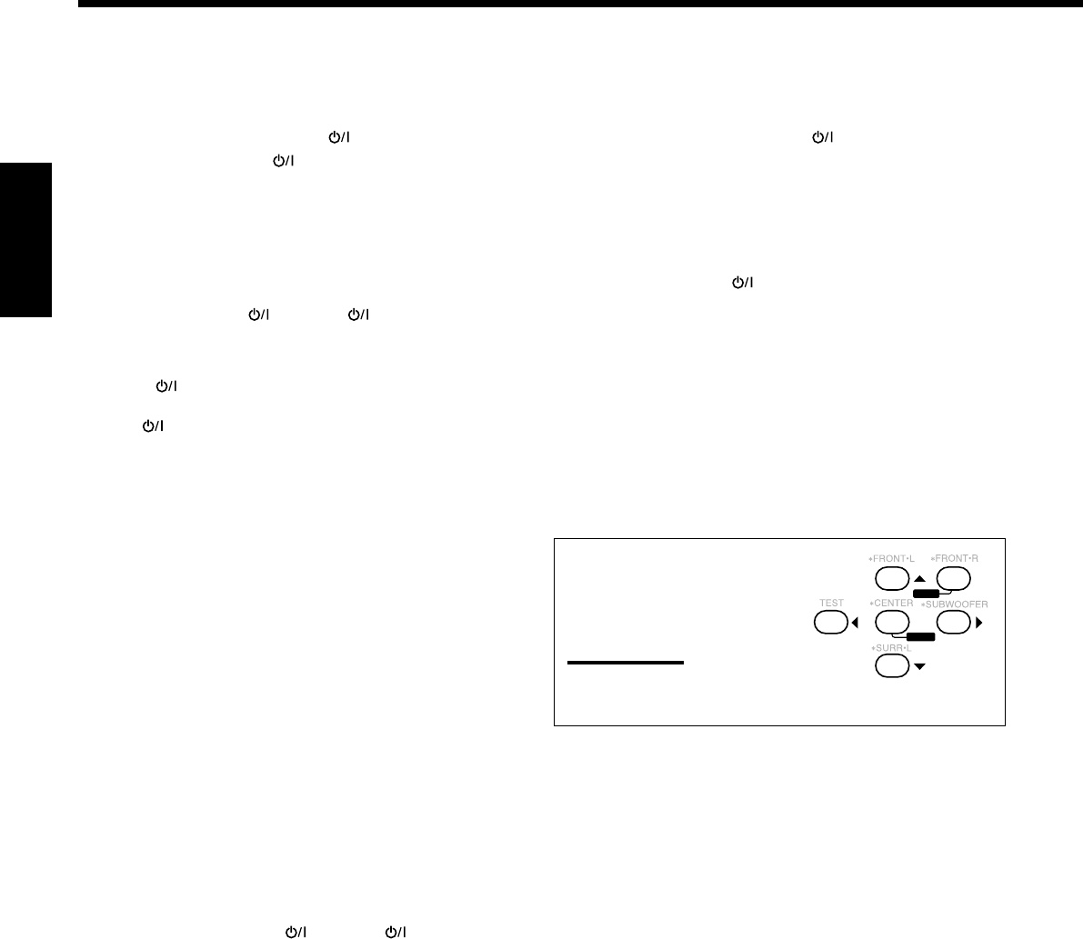
48
Français
Pour changer les signaux émettables pour
commander le lecteur de DVD d’un autre
fabricant
1. Maintenez pressée AUDIO .
2 Appuyez sur DVD.
3. Entrez le code du fabricant en utilisant les
touches numériques 1 – 9 et 0.
Référez-vous à la liste de la page 49 pour trouver le code.
4. Relâchez AUDIO .
Après avoir appuyé sur DVD ou DVD MULTI, vous pouvez
réaliser les opérations suivantes sur le lecteur de DVD:
3:Démarrer la lecture.
4: Retourner au début du chapitre actuel (ou précédent).
¢: Sauter au début du chapitre suivant.
7: Arrêter la lecture.
8:Arrêter momentanément la lecture. Pour reprendre,
appuyez sur 3.
Après avoir appuyé sur DVD ou
DVD MULTI, ces touches peuvent
être utilisées pour commander le
menu de DVD.
Remarque:
Pour les opérations détaillées
concernant le menu DVD, se référer aux instructions fournies avec
les disques ou le lecteur de DVD.
5. Essayez de commander votre lecteur de DVD en
appuyant sur une des touches ci-dessus.
•N’OUBLIEZ PAS de mettre le lecteur de DVD sous tension
avant d’appuyer sur une de ces touches.
S’il y a plus d’un code pour votre marque de lecteur de
DVD, essayez chaque code jusqu’à ce que vous trouviez le bon.
23
456
8
MENU
MENU
ENTER
ENTER
Pour changer les signaux émettables pour
commander le magnétoscope d’un autre
fabricant
1. Maintenez pressée VCR 1 (pour le RX-
8030VBK) ou VCR (pour le RX-7030VBK).
2. Appuyez sur VCR 1 (pour le RX-8030VBK) ou
VCR (pour le RX-7030VBK).
3. Entrez le code du fabricant en utilisant les
touches numériques 1 – 9 et 0.
Référez-vous à la liste de la page 49 pour trouver le code.
4. Relâchez VCR 1 ou VCR .
Les touches suivantes peuvent être utilisées pour commander le
magnétoscope:
VCR 1 :Pour le RX-8030VBK—Met sous ou hors
tension le magnétoscope.
VCR :Pour le RX-7030VBK—Met sous ou hors
tension le magnétoscope
Après avoir appuyé sur VCR 1 ou VCR, vous pouvez réaliser les
opérations suivantes sur le magnétoscope:
CH +/–:Changer les canaux de téléviseur sur le
magnétoscope.
1 – 10/0, 0, 100+ (+10):
Choisir les canaux de télévision.
La touche numérique 10/0 fonctionne comme
touche ENTER si votre magnétoscope
nécessite que vous appuyiez sur la touche
ENTER après avoir choisi un numéro de canal.
3:Démarrer la lecture.
REW: Rebobiner la bande.
FF: Avancer rapidement la bande.
7:Arrêter la lecture ou l’enregistrement.
8:Arrêter momentanément la lecture. Pour
reprendre, appuyez sur 3.
REC PAUSE: Entrer en mode de pause à l’enregistrement en
appuyant sur cette touche.
Pour reprendre l’enregistrement, appuyez sur
cette touche plus sur 3.
5. Essayez de commander votre magnétoscope en
appuyant sur VCR 1 ou VCR .
Si le magnétoscope se met sous ou hors tension, c’est que vous
avez entré le bon code.
S’il y a plus d’un code pour votre marque de magnétoscope,
essayez chaque code jusqu’à ce que vous trouviez le bon.
FR42-52_8030&7030[C]f.pm6 03.2.12, 6:03 PM48
49
Français
Fabricant Codes
JVC 00*, 02
Denon 01
Panasonic 03
Philips 13
Pioneer 04, 05, 06
RCA 07
Samsung 08
Sony 09
Toshiba 10
Yamaha 11, 12
Les codes de fabricants sont sujets à changement sans notification.
S’ils sont changés, cette télécommande ne pourra par commander
l’appareil.
Fabricant Codes
JVC 00*, 26, 27, 28, 29, 58
Aiwa 01, 02
Bell & Howell 03
Blaupunkt 04, 05
CGM 06, 07
Emerson 08, 10, 11, 12, 64, 65
Fisher 03, 14, 15, 16, 17
Funai 01
GE 18, 19, 20
Goldstar 07
Goodmans 13, 21
Grundig 06, 22
Hitachi 18, 23, 24, 25, 66
Loewe 07, 21
Magnavox 04, 19, 24
Mitsubishi 30, 31, 32, 33, 34, 35
NEC 26, 27
Nokia 03, 36
Nordmende 38
Orion 09
Panasonic 19, 24, 39, 40
Philips 04, 19, 21, 24, 41, 42
Phonola 21
RCA/Proscan 04, 18, 19, 23, 24, 43, 44, 45
SABA 38, 46
Samsung 45, 47, 59, 61, 62, 63
Sanyo 03, 48, 49
Sharp 37, 50
Siemens 03, 51
Sony 52, 53, 54
Telefunken 55, 60
Toshiba 43, 44
Zenith 56, 57
Pour le convertisseur CATV
Fabricant Codes
General Instrument 06, 07, 08, 09, 10, 11,
12, 13, 14, 29
Hamlin/Regal 01, 02, 03, 04, 05
Jerrold 06, 07, 08, 09, 10, 11,
12, 13, 14
Oak 15, 16, 17
Panasonic 18, 19, 20
Pioneer 21, 22
Scientific Atlanta 23, 24, 25
Tocom 26
Zenith 27, 28
Fabricant Codes
JVC 56*, 57, 67
Amstrad 43, 44, 45, 46, 47, 48, 49
Blaupunkt 30
Echostar 50, 51, 67
Goldstar 31
Grundig 32, 33
Hirshmann 48, 52, 53, 54, 55
Instrument 68
ITT/NOKIA 34
Kathrein 52, 58, 59, 60, 61, 62, 63
NEC 35, 36
Orbitech 48
Philips 37, 38
RCA 65
Samsung 39, 40
Schwaiger 61, 64
Siemens 41, 42
Sony 66
Technisat 48
Pour le tuner DBS
*réglage initial
Fabricant Codes
JVC 00*, 02, 13,
14, 47, 74
Akai 01, 02
Blaupunkt 03, 04
Fisher 01, 05
Grundig 03, 06, 07
Hitachi 08, 09, 10, 49
Irradio 02
ITT/NOKIA 11, 12
Loewe 06, 15, 16
Magnavox 08, 17, 49
Mets 50, 51, 52, 53
Mitsubishi 08, 18, 19, 20
Mivar 21
Nordmende 22, 23
Okano 15
Panasonic 24, 25, 26, 27
76
Philips 15, 17, 28, 75
Fabricant Codes
Quelle 52, 53, 54, 55,
56, 57, 58, 59,
60, 61, 62, 63,
64, 65, 66, 67
RCA/ 08, 24, 29, 30,
Proscan 31, 48
SABA 32, 33, 68, 69,
70
Samsung 06, 08, 16, 34,
35, 49
Sanyo 01, 05
Schneider 02, 15, 36
Sharp 37, 38, 77
Sony 39
Telefunken 40, 41, 42, 69
Thomson 71, 72
Toshiba 37, 43, 44
Zenith 45, 46
Pour le téléviseur Pour le magnétoscope
Pour le lecteur de DVD
FR42-52_8030&7030[C]f.pm6 03.2.12, 6:03 PM49
50
Français
Guide de dépannage
Utilisez ce tableau pour vous aider à résoudre les problèmes de fonctionnement quotidiens. Si certains problèmes ne
peuvent pas être résolus, contacter un centre de réparation JVC.
SOLUTION
Brancher le cordon d’alimentation sur une prise secteur.
Vérifier le câblage des enceintes et reconnecter si
nécessaire.
(Voir pages 9 à 11.)
Positionner les touches SPEAKERS ON/OFF 1 et
SPEAKERS ON/OFF 2 correctement. (Voir page 19.)
Choisir la source correcte.
Appuyer sur MUTING l’annuler. (Voir page 22.)
Choisissez le mode d’entrée correct (analogique ou
numérique). (Voir page 19.)
Vérifier le câblage des enceintes et reconnecter si
nécessaire.
(Voir pages 9 à 11.)
Connecter une antenne FM extérieure ou contacter le
revendeur local. (Voir page 8.)
Choisir une nouvelle station.
Vérifier avec le revendeur local pour s’assurer que
l’antenne est correcte.
Vérifier les connexions. (Voir page 8.)
Eloigner l’antenne du trafic automobile.
Connecter le câble à la vis marquée (H) sur le
panneau arrière.
Eloigner les enceintes du tourne-disque.
Mettre hors service la fonction Analog Direct. (Voir
page 21.)
Choisissez une autre source que DVD MULTI. (Voir
page 40.)
Reproduire un logiciel portant la marque
ou .
Régler “EX/ES” sur “ON”. (Voir page 37.)
1. Appuyer sur STANDBY/ON sur le panneau
avant pour mettre l’ampli-tuner sous tension.
2. Arrêter la source de lecture.
3. Mettez l’ampli-tuner sous tension et ajuster le volume.
Appuyer sur STANDBY/ON sur le panneau avant,
puis vérifier le câblage des enceintes.
Si “OVERLOAD” ne disparaît pas, débrancher le
cordon d’alimentation, puis le rebrancher.
Si le câblage d’enceinte n’est pas court-circuité,
contacter le revendeur local.
Appuyer STANDBY/ON sur le panneau avant
pour mettre l’ampli-tuner hors tension. Débrancher le
cordon d’alimentation et consulter votre revendeur.
Retirer l’obstacle.
Remplacer les piles. (Voir page 8.)
Choisir le mode de fonctionnement de télécommande
correct. (Voir pages 44 à 49.)
CAUSE POSSIBLE
Le cordon d’alimentation n’est pas branché.
Les câbles de signal d’enceinte ne sont
pas connectés.
Les touches SPEAKERS ON/OFF 1 et
SPEAKERS ON/OFF 2 ne sont pas
positionnées correctement.
Une source incorrecte est choisie.
La mise en sourdine est en service.
Un mode d’entrée incorrect (analogique
ou numérique) est choisi.
Les câbles de signal d’enceinte ne sont
pas connectés correctement.
Le signal est trop faible.
La station est trop éloignée.
Une antenne incorrecte est utilisée.
Les antennes sont connectées incorrectement.
Bruit d’ignition provenant d’automobiles.
Le câble de mise à la terre du tourne-
disque n’est pas connecté à la vis marquée
(H) sur le panneau arrière.
Le tourne-disque est trop près des
enceintes.
La fonction Analog Direct est en service.
DVD MULTI est choisi comme source.
Le support ou le réglage n’est pas pour les
logiciels Dolby Digital EX ou DTS ES.
Les enceintes sont surchargées à cause
d’un volume élevé.
Les enceintes sont surchargées à cause
d’un court-circuit des prises d’enceinte.
L’ampli-tuner est surchargé à cause d’une
haute tension.
Il y a un obstacle entre le capteur de
télécommande sur l’ampli-tuner et la
télécommande.
Les piles sont faibles.
Un mode de fonctionnement de
télécommande incorrect est choisi.
PROBLÈME
L’affichage ne s’allume pas.
Aucun son ne sort des enceintes.
Le son sort seulement d’une enceinte.
Souffle ou ronflement continu pendant la
réception FM.
Bruit de craquement occasionnel pendant
la réception FM/AM.
Hurlement pendant la reproduction d’un
disque analogique.
Aucun effet sonore tel que le mode Surround,
le mode DSP et l’égalisation numérique.
La reproduction EX/ES (7,1 canaux) ne
peut pas être utilisée pour un logiciel
Dolby Digital EX ou DTS ES.
“OVERLOAD” clignote sur l’affichage.
Le témoin STANDBY s’allume après que
l’appareil a été mis sous tension, mais
l’ampli-tuner se remet aussitôt hors
tension (en mode d’attente).
La télécommande ne fonctionne pas.
La télécommande ne fonctionne pas
comme souhaitée.
FR42-52_8030&7030[C]f.pm6 03.2.12, 6:03 PM50

51
Français
RX-8030VBK
Amplificateur
Puissance de sortie
Pendant une opération stéréo
Ca. avant: 130 W par canal, min. RMS, entraîné sur 8 Ω,
20 Hz à 20 kHz, avec moins de 0,08% de
distorsion harmonique totale.
Pendant une opération Surround:
Ca. avant: 130 W par canal, min. RMS, entraîné sur 8 Ω à
1 kHz, avec moins de 0,8% de distorsion
harmonique totale.
Ca. central: 130 W, min. RMS, entraîné sur 8 Ω à
1 kHz, avec moins de 0,8% de distorsion
harmonique totale.
Ca. Surround:130 W par canal, min. RMS, entraîné sur 8 Ω à
1 kHz, avec moins de 0,8% de distorsion
harmonique totale.
Ca. Surround arrière:
130 W, min. RMS, entraîné sur 8 Ω à
1 kHz, avec moins de 0,8% de distorsion
harmonique totale.
Audio
Sensibilité d’entrée audio/Impédance (1 kHz)
PHONO IN (MM): 2,5 mV/47 kΩ
DVD IN, VCR 1 IN, VCR 2 IN, TV SOUND/DBS IN, VIDEO IN:
200 mV/47 kΩ
CD IN, CDR IN, TAPE/MD IN: 200 mV/47 kΩ
Entrée audio (DIGITAL IN)*
Coaxiale: DIGITAL 1 (DVD): 0,5 V(c-c)/75 Ω
Optique:
DIGITAL 2 (CD), DIGITAL 3 (TV), DIGITAL 4 (CDR):
–21 dBm à –15 dBm (660 nm ±30 nm)
* Correspondant à Linear PCM, Dolby Digital et DTS Digital
Surround (avec une fréquence d’échantillonnage — 32 kHz,
44,1 kHz, 48 kHz).
Niveau de sortie audio: PRE OUT: 1 V
Niveau de sortie d’enregistrement:
VCR 1 OUT, VCR 2 OUT, CDR OUT,
TAPE/MD OUT: 200 mV
Sortie numérique: Optique: DIGITAL OUTPUT
Longueur d’onde du signal: 660 nm
Niveau de sortie: –21 dBm à –15 dBm
Rapport signal sur bruit (’66 IHF/’78 IHF)
PHONO IN: 70 dB/78 dB (à REC OUT)
DVD IN, VCR 1 IN, VCR 2 IN, TV SOUND/DBS IN, VIDEO:
87 dB/80 dB
CD IN, CDR IN, TAPE/MD IN: 87 dB/80 dB
Réponse en fréquence (8 Ω)
PHONO IN: 20 Hz à 20 kHz (±1 dB)
DVD IN, VCR 1 IN, VCR 2 IN, TV SOUND/DBS IN, VIDEO:
20 Hz à 100 kHz (+1 dB, –3 dB)
CD IN, CDR IN, TAPE/MD IN: 20 Hz à 100 kHz (+1 dB, –3 dB)
Égalisation Phono RIAA: ±1,0 dB (20 Hz à 20 kHz)
Égalisation (5 bandes): 63 Hz, 250 Hz, 1 kHz, 4 kHz, 16 kHz (±8 dB)
Accentuation des graves: +6 dB ±1,0 dB à 100 Hz
Spécifications
Vidéo
Sensibilité d’entrée vidéo/Impédance
Vidéo composite:
DVD IN, VCR 1 IN, VCR 2 IN, TV SOUND/DBS IN, VIDEO:
1 V(c-c)/75 Ω
S-vidéo:
DVD IN, VCR 1 IN, VCR 2 IN, TV SOUND/DBS IN, VIDEO:
(Y: luminance): 1 V(c-c)/75 Ω
(C: chrominance, en salve): 0,286 V(c-c)/75 Ω
Composantes vidéo: DVD IN, DBS IN:
(Y: luminance): 1 V(c-c)/75 Ω
(PB/PR): 0,7 V(c-c)/75 Ω
Niveau de sortie vidéo
Vidéo composite:
VCR 1 OUT, VCR 2 OUT, MONITOR OUT 1 V(c-c)/75 Ω
S-vidéo: VCR 1 OUT, VCR 2 OUT, MONITOR OUT
(Y: luminance): 1 V(c-c)/75 Ω
(C: chrominance, en salve): 0,286 V(c-c)/75 Ω
Composantes vidéo: MONITOR OUT:
(Y: luminance): 1 V(c-c)/75 Ω
(PB/PR): 0,7 V(c-c)/75 Ω
Synchronisation: Négative
Rapport signal sur bruit: 45 dB
Tuner FM (IHF)
Plage d’accord: 87,5 MHz à 108,0 MHz
Sensibilité utile: Monaural: 12,8 dBf (1,2 µV/75 Ω)
Sensibilité utile à 50 dB: Monaural: 16,0 dBf (1,7 µV/75 Ω)
Stéréo: 37,5 dBf (20,5 µV/75 Ω)
Séparation stéréo à REC OUT: 35 dB à 1 kHz
Tuner AM
Plage d’accord: 530 kHz à 1 710 kHz
Général
Alimentation: Secteur 120V , 60 Hz
Consommation: 320 W/440 VA (pendant le fonctionnement)
2 W (en mode d’attente)
Dimensions (L x H x P): 435 mm x 157 mm x 425 mm
(17 3/16 po. x 6 3/16 po. x 16 3/4 po.)
Masse: 12,2 kg (27,0 livres)
La conception et les spécifications sont sujettes à changement sans
notification.
FR42-52_8030&7030[C]f.pm6 03.2.12, 6:03 PM51

52
Français
.
RX-7030VBK
Amplificateur
Puissance de sortie
Pendant une opération stéréo
Ca. avant: 110 W par canal, min. RMS, entraîné sur 8 Ω,
20 Hz à 20 kHz, avec moins de 0,08% de
distorsion harmonique totale.
Pendant une opération Surround:
Ca. avant: 110 W par canal, min. RMS, entraîné sur 8 Ω à
1 kHz, avec moins de 0,8% de distorsion
harmonique totale.
Ca. central: 110 W, min. RMS, entraîné sur 8 Ω à
1 kHz, avec moins de 0,8% de distorsion
harmonique totale.
Ca. Surround:110 W par canal, min. RMS, entraîné sur 8 Ω à
1 kHz, avec moins de 0,8% de distorsion
harmonique totale.
Ca. Surround arrière:
110 W, min. RMS, entraîné sur 8 Ω à
1 kHz, avec moins de 0,8% de distorsion
harmonique totale.
Audio
Sensibilité d’entrée audio/Impédance (1 kHz)
DVD IN, VCR IN, TV SOUND/DBS IN:
200 mV/47 kΩ
CD IN, TAPE/CDR IN: 200 mV/47 kΩ
Entrée audio (DIGITAL IN)*
Coaxiale: DIGITAL 1 (DVD): 0,5 V(c-c)/75 Ω
Optique:
DIGITAL 2 (CD), DIGITAL 3 (TV), DIGITAL 4 (CDR):
–21 dBm à –15 dBm (660 nm ±30 nm)
* Correspondant à Linear PCM, Dolby Digital et DTS Digital
Surround (avec une fréquence d’échantillonnage — 32 kHz,
44,1 kHz, 48 kHz).
Niveau de sortie audio: SUBWOOFER OUT: 1 V
Niveau de sortie d’enregistrement:
VCR OUT, TAPE/CDR OUT: 200 mV
Sortie numérique: Optique: DIGITAL OUT
Longueur d’onde du signal: 660 nm
Niveau de sortie: –21 dBm à –15 dBm
Rapport signal sur bruit (’66 IHF/’78 IHF)
DVD IN, VCR IN, TV SOUND/DBS IN: 87 dB/80 dB
CD IN, TAPE/CDR IN: 87 dB/80 dB
Réponse en fréquence (8 Ω)
DVD IN, VCR IN, TV SOUND/DBS IN:
20 Hz à 100 kHz (+1 dB, –3 dB)
CD IN, TAPE/CDR IN: 20 Hz à 100 kHz (+1 dB, –3 dB)
Égalisation (5 bandes): 63 Hz, 250 Hz, 1 kHz, 4 kHz, 16 kHz (±8 dB)
Accentuation des graves: +6 dB ±1,0 dB à 100 Hz
Vidéo
Sensibilité d’entrée vidéo/Impédance
Vidéo composite: DVD IN, VCR IN, TV SOUND/DBS IN:
1 V(c-c)/75 Ω
S-vidéo:
DVD IN, VCR IN, TV SOUND/DBS IN:
(Y: luminance): 1 V(c-c)/75 Ω
(C: chrominance, en salve): 0,286 V(c-c)/75 Ω
Composantes vidéo: DVD IN, DBS IN:
(Y: luminance): 1 V(c-c)/75 Ω
(PB/PR): 0,7 V(c-c)/75 Ω
Niveau de sortie vidéo
Vidéo composite: VCR OUT, MONITOR OUT 1 V(c-c)/75 Ω
S-vidéo: VCR OUT, MONITOR OUT
(Y: luminance): 1 V(c-c)/75 Ω
(C: chrominance, en salve): 0,286 V(c-c)/75 Ω
Composantes vidéo: MONITOR OUT:
(Y: luminance): 1 V(c-c)/75 Ω
(PB/PR): 0,7 V(c-c)/75 Ω
Synchronisation: Négative
Rapport signal sur bruit: 45 dB
Tuner FM (IHF)
Plage d’accord: 87,5 MHz à 108,0 MHz
Sensibilité utile: Monaural: 12,8 dBf (1,2 µV/75 Ω)
Sensibilité utile à 50 dB: Monaural: 16,0 dBf (1,7 µV/75 Ω)
Stéréo: 37,5 dBf (20,5 µV/75 Ω)
Séparation stéréo à REC OUT: 35 dB à 1 kHz
Tuner AM
Plage d’accord: 530 kHz à 1 710 kHz
Général
Alimentation: Secteur 120V , 60 Hz
Consommation: 320 W/440 VA (pendant le fonctionnement)
2 W (en mode d’attente)
Dimensions (L x H x P): 435 mm x 157 mm x 425 mm
(17 3/16 po. x 6 3/16 po. x 16 3/4 po.)
Masse: 12,1 kg (26,7 livres)
La conception et les spécifications sont sujettes à changement sans
notification.
FR42-52_8030&7030[C]f.pm6 03.2.12, 6:03 PM52

EN, FR
0203NHMMDWJEIN
© 2003 VICTOR COMPANY OF JAPAN, LIMITED
VICTOR COMPANY OF JAPAN, LIMITED
COVER_8030&7030[C]7.pm6 03.2.13, 2:53 PM2
