JVCKENWOOD 371412 UHF Transmitter User Manual
JVC KENWOOD Corporation UHF Transmitter Users Manual
Contents
- 1. Users Manual
- 2. Users Manual Safety Info
Users Manual

NXR-700/ NXR-800
© B62-XXXX-00 (E)
09 08 07 06 05 04 03 02 01 00
VHF DIGITAL BASE-REPEATER/ UHF DIGITAL BASE-REPEATER
INSTRUCTION MANUAL
BASE-RELAIS NUMÉRIQUE VHF/ BASE-RELAIS NUMÉRIQUE UHF
MODE D'EMPLOI
BASE-REPETIDOR DIGITAL VHF / BASE-REPETIDOR DIGITAL UHF
MANUAL DE INSTRUCCTIONES
BASE-RIPETITORE DIGITALE VHF/ BASE-RIPETITORE DIGITALE UHF
MANUALE DI ISUTRUZIONI
VHF DIGITAL BASE-REPEATER/ UHF DIGITAL BASE-REPEATER
BEDIENUNGSANLEITUNG
VHF DIGITALE BASIS REPEATER/ UHF DIGITALE BASIS REPEATER
GEBRUIKSAANWIJZING
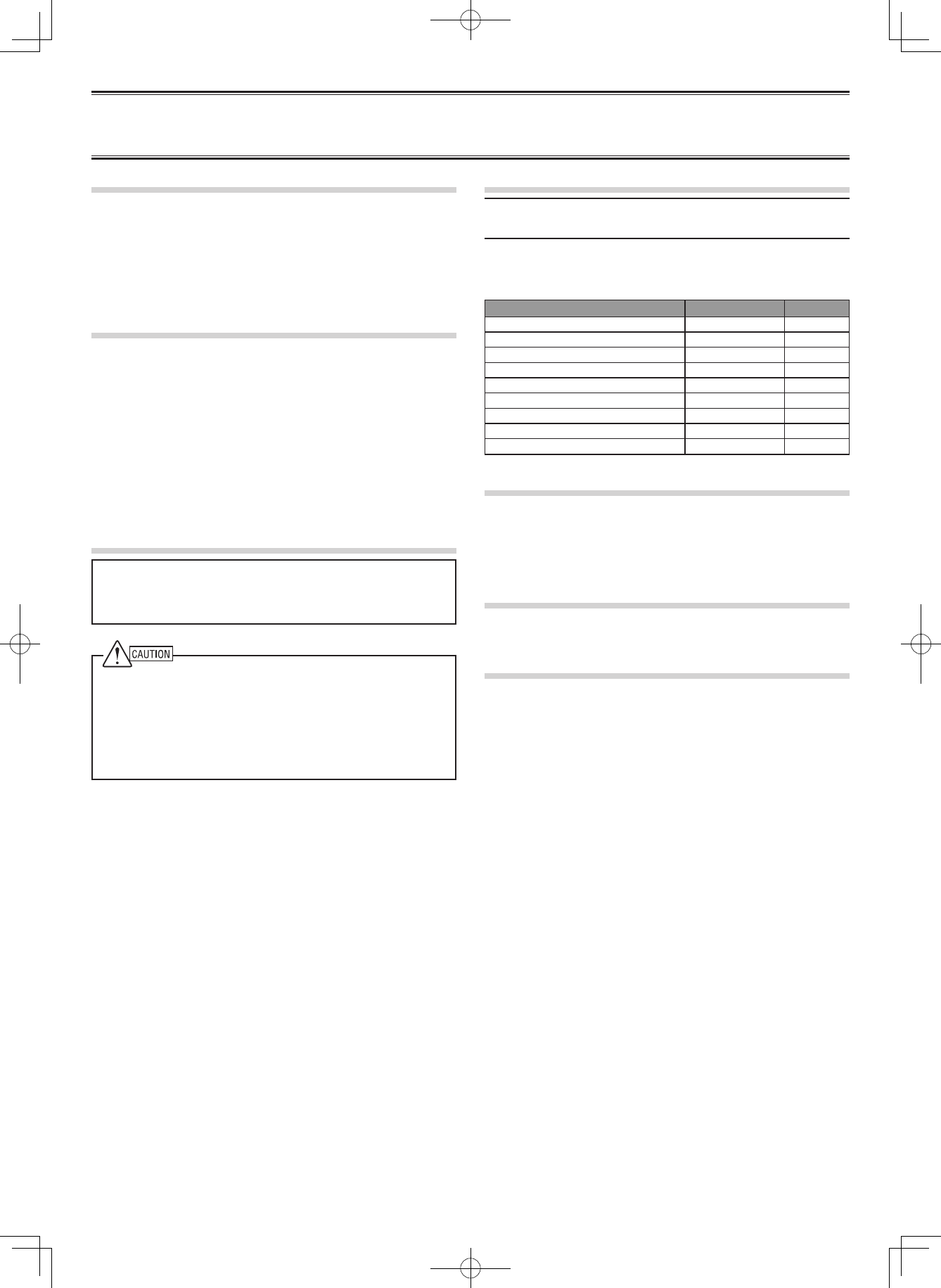
UNPACKING AND CHECKING EQUIPMENT
Note: The following unpacking information is for use by your
Kenwood dealer, an authorized Kenwood service center, or the
factory.
Carefully unpack the repeater. We recommend that you identify
the items listed in the following table before discarding the
packing material. If any items are missing or have been damaged
during shipment, le a claim with the carrier immediately.
Item Part Number Quantity
Front glass B10-2781-XX 1
Dressed screw N08-0563-XX 1
Bracket J29-0725-XX 2
Flat head machine screw N32-4008-XX 4
Handle and screw set K01-0421-XX 1
DC cord E30-3344-XX 1
Lead wire with connector (15 pin) E37-1381-XX 1
Fuse (15 A) F05-1537-XX 1
Instruction Manual B62-XXXX-XX 1
INSTALLATION
To install the handles onto the front panel of the repeater, align
the handles with the holes on the front panel, then secure the
handles using the supplied screws.
Please consult your dealer for installing the repeater and
antenna.
MICROPHONE
Connect an optional KMC-30, KMC-35, or KMC-9C Kenwood
microphone to the MICROPHONE jack on the front panel.
OCXO UNIT (KXK-3):Option
The OCXO unit (KXK-3) is an Oven Controlled Crystal Oscillator
(OCXO) unit.
NOTICES TO THE USER
◆ Government law prohibits the operation of unlicensed radio
transmitters within the territories under government control.
◆ Illegal operation is punishable by ne and/or imprisonment.
◆ Refer service to qualied technicians only.
◆ This repeater is intended for use as a xed base station with
the antenna located outdoors on the rooftop or on an antenna
tower. (except U.S.A. and Canada)
◆ This repeater is designed for a 13.2 V DC power source!
Never use a 24 V DC or higher source to power the repeater.
◆ Use only the supplied DC cord.
◆ Do not remove the ferrite core attached to the DC cord. Doing
so may cause interference with radio communications.
The AMBE+2 voice coding Technology embodied in this product
is protected by intellectual property rights including patent rights,
copyrights and trade secrets of Digital Voice Systems, Inc. This voice
coding Technology is licensed solely for use within this Communications
Equipment. The user of this Technology is explicitly prohibited from
attempting to extract, remove, decompile, reverse engineer, or
disassemble the Object Code, or in any other way convert the Object
Code into a human-readable form. U.S. Patent Nos. #5,870,405,
#5,826,222, #5,754,974, #5,701,390, #5,715,365, #5,649,050,
#5,630,011, #5,581,656, #5,517,511, #5,491,772, #5,247,579, #5,226,084
and #5,195,166.
THANK YOU!
We are grateful you purchased this Kenwood repeater. We
believe this easy-to-program repeater will be highly effective in
your communications system, and will keep personnel operating
at peak efciency.
Kenwood incorporates the latest in advanced technology into
all of our products. As a result, we feel strongly that you will be
pleased with the quality and features of this product.
PRECAUTIONS
• Do not expose the unit to rain or moisture; to prevent re or
electric shock.
• Do not open the unit under any circumstances; to avoid risk
of electric shock.
• Do not expose the unit to long periods of direct sunlight, nor
place it close to heating appliances.
• Do not place the unit in excessively dusty and/or humid
areas, nor on unstable surfaces.
• If you detect an abnormal odor or smoke coming from the
unit, disconnect the power from the unit immediately. Contact
your Kenwood service center or dealer.
NXR-700 / NXR-800 INSTRUCTION MANUAL
VHF DIGITAL BASE-REPEATER / UHF DIGITAL BASE-REPEATER
REPEATER OPERATION
Note: Please consult your dealer for programming the repeater. Due
to the frequency stability on the 6.25 kHz bandwidth channel, when
operating the repeater using an optional OCXO unit, allow the unit to
warm up for 24 hours after turning the power on.
After turning on the power, wait for approximately 10 seconds for
the VCXO or 5 minutes for the OCXO (when mounting) to warm up.
During this time, the CH/STATUS Display will blink. The keys will
function when they are pressed.
When power is applied to the unit, the POWER indicator lights
green. Turn the VOLUME control clockwise until a click sounds,
to unmute the audio. Rotate to adjust the audio. Turn the
VOLUME control counterclockwise fully to mute the audio.
The BUSY indicator lights green while receiving a signal and the
TX indicator lights red while transmitting.
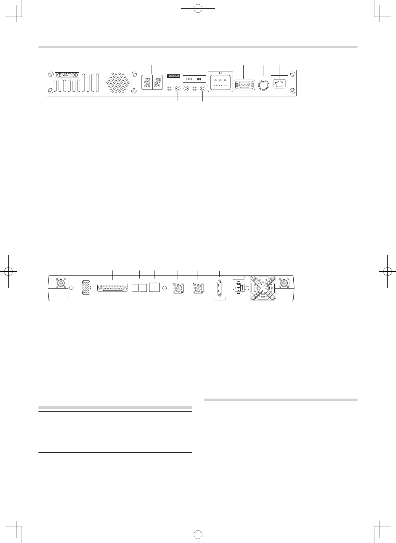
■ Rear Panel
q RX IN jack
Connect an RX antenna or a duplexer to this BNC
receptacle.
w TEST/SPKR jack
Test input/output jack. Connect an external speaker to
this jack.
e CONTROL I/O jack
Connect a repeater controller or a remote panel to this
DB-25 interface.
r SYNC 1 / 2 jack
Connect to another repeater to use synchronous frame
signaling for digital trunking.
t LAN jack
Connect to Ethernet.
CONTROLS AND FUNCTIONS
■ Front Panel qw r t y u
io
e
qwrt y u
e
MICROPHONE
VOLUME
COM OFF/
POWERCTRL OCXO BUSY TX
1 2
MON
TAKE
OVER
RPT
DISABLE
A B C
3 4 5 6 7 8
STATUS
TEST/SPKR
RX TX
CONTROL I/O SYNC
1 2 LAN REF OUT REF IN
FUSE
15
DC 13.2V
FUSE 15A
y REF OUT jack
Connect to another repeater within the site to supply a
reference signal.
u REF IN jack
Connect from another repeater within the site to receive a
reference signal.
i FUSE
Insert 15 A blade fuse into this fuse holder.
o DC 13.2V jack
Connect a 13.2 V DC power supply to this jack.
⑩ TX OUT jack
Connect a TX antenna or a duplexer to this BNC receptacle.
io⑩
TRANSCEIVER OPERATION
■ Receive
Adjust the volume to your desired level. You may need to
readjust the volume if you are having interference while
receiving a message from your dispatcher or another member
in your eet.
The BUSY indicator lights green while a signal is being
received.
■ Transmit
1 Listen to the channel before transmitting, to make sure it
is not being used.
2 Press the microphone PTT switch, then speak in your
normal speaking voice.
The TX indicator lights red while transmitting.
3 When you nish speaking, release the PTT switch.
!0
!1
!2
q Speaker
w CH/STATUS Display
Two 17-segment digits display the channel number, name,
or status.
e STATUS indicator
Indicates the status of the repeater. (NXDN mode)
r Programmable Function keys
Press these keys to activate their programmable
functions.
t COM jack
Connect to the PC using a RS-232C standard DB9
(Female) cross cable.
y VOLUME control
Turn clockwise until a click sounds, to unmute the audio.
Rotate to adjust the audio. Turn counterclockwise fully to
mute the audio.
u MICROPHONE jack
Connect a microphone to this 8-pin modular jack.
i POWER indicator
Lights green when power is supplied to the DC 13.2V
jack. Blinks red when an abnormal voltage is present.
While blinking, the repeater cannot be used.
o TX indicator
Lights red while transmitting.
!0 BUSY indicator
Lights green while a signal is being received.
!1 OCXO indicator
The OCXO indicator shows the state of the reference
10 MHz oscillator :
Lights Green when using a reference signal from an
optional OCXO unit (KXK-3).
Lights Orange when using a reference signal from another
repeater.
Lights red when no reference signal is available or when
an error occurs.
Does not light when the reference signal is an internal
VCXO signal.
!2 CTRL indicator
The CTRL indicator shows the control channel status
while using Digital trunking :
Lights Green when the repeater is used as control channel.
Blinks Green when using a non-dedicated control channel.
AVISO
Este equipo cumple con los requisitos esenciales de la Directiva
1999/5/CE.
El uso del símbolo de advertencia signica que el equipo está
sujeto a restricciones de uso en ciertos países.
Este equipo requiere una licencia y está destinado para utilizarse
en los siguientes países.
AT BE DK FI FR DE GR IS
IE IT LI LU NL NO PT ES
SE CH GB CY CZ EE HU LV
LT MT PL SK SI BG RO
ISO3166
NOTIFICATION
This equipment complies with the essential requirements of
Directive 1999/5/EC.
The use of the warning symbol means the equipment is subject
to restrictions of use in certain countries.
This equipment requires a licence and is intended for use in the
countries as below.
NOTIFICATION
Cet équipement est conforme aux principales exigences de la
Directive 1999/5/CE.
L’usage du symbole d’avertissement signie que l’équipement
est soumis à des restrictions d’usage dans certains pays.
Cet équipement nécessite un contrat de licence et il est destiné à
être utilisé dans les pays ci-dessous.
AVVISO
La presente apparecchiatura è conforme ai requisiti fondamentali della
Direttiva 1999/5/CE.
L’uso del simbolo di avvertenza indica che l’apparecchiatura è
soggetta alle limitazioni d’uso in vigore in determinati paesi.
Questa apparecchiatura e’concepita per essere utilizzata in tutti
L’apparecchiatura deve essere provvista di licenza e n’è consentito
l'uso nei seguenti paesi.
HINWEIS
Dieses Gerät erfüllt die grundlegenden Anforderungen der Direktive
1999/5/EG.
Das Alert-Zeichen be-deutet, dass dieses Gerät in manchen Ländern
bestimmten Verwendung-seinschränkungen unterliegt.
Für dieses Gerät ist eine Lizenz erforderlich; es ist für die Verwendung
in den unten aufgeführten Ländern vorgesehen.
KENNISGEVING
Deze apparatuur voldoet aan de vereisten van Richtlijn 1999/5/EG.
Het gebruik van het waarschuwings-symbool betekent dat dit apparaat
in bepaalde landen aan gebruiksbe-perkingen onderhevig is.
Voor deze apparatuur is een licentie nodig en is bedoeld voor gebruik
in onderstaande landen.
AT BE DK FI FR DE GR IS
IE IT LI LU NL NO PT ES
SE CH GB CY CZ EE HU LV
LT MT PL SK SI BG RO ISO3166
B59-2669-00
One or more of the following statements may be applicable:
FCC WARNING
This equipment generates or uses radio frequency energy.
Changes or modications to this equipment may cause harmful
interference unless the modications are expressly approved
in the instruction manual. The user could lose the authority to
operate this equipment if an unauthorized change or modication
is made.
INFORMATION TO THE DIGITAL DEVICE USER REQUIRED
BY THE FCC
This equipment has been tested and found to comply with the
limits for a Class B digital device, pursuant to Part 15 of the
FCC Rules. These limits are designed to provide reasonable
protection against harmful interference in a residential
installation.
This equipment generates, uses and can generate radio
frequency energy and, if not installed and used in accordance
with the instructions, may cause harmful interference to radio
communications. However, there is no guarantee that the
interference will not occur in a particular installation. If this
equipment does cause harmful interference to radio or television
reception, which can be determined by turning the equipment off
and on, the user is encouraged to try to correct the interference by
one or more of the following measures:
• Reorient or relocate the receiving antenna.
• Increase the separation between the equipment and
receiver.
• Connect the equipment to an outlet on a circuit different from
that to which the receiver is connected.
• Consult the dealer for technical assistance.
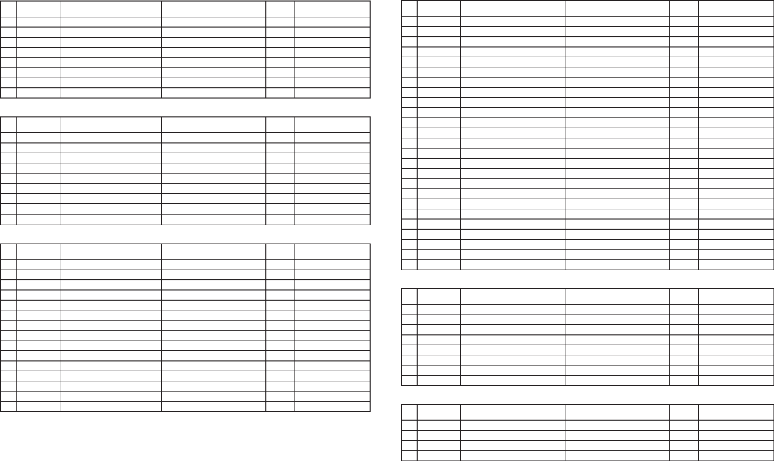
Addendum
Terminal Description
MIC (Modular Jack)
Pin
NO. Pin Name Description Specification I/O Notes
1 NC Not used Not used −
2 SB Power Output 13.8 V O
3 GND GND GND −
4 PTT PTT Signal Input Impedance 100 kΩ I
5 MICG MIC GND MIC GND −
6 MIC MIC Input 600 Ω I
7 HOOK Hook Detection Input Impeadance 100 kΩ I
8 NC Not used Not used −
COM (D-SUB 9 Pin) CONNECTOR
Pin
NO. Pin Name Description Specification I/O Notes
1 CD Carrier Detect Conform to RS-232C standard I
2 RD Receive Data Conform to RS-232C standard I
3 SD Send Data Conform to RS-232C standard O
4 DTR Data Terminal Ready Conform to RS-232C standard O
5 SG GND GND −
6 DSR Data Set Ready Conform to RS-232C standard I
7 RTS Request to Send Conform to RS-232C standard O
8 CTS Clear to Send Conform to RS-232C standard I
9 CI Ringer DET Conform to RS-232C standard I
TEST/ SPEAKER CONNECTOR
Pin
NO. Pin Name Description Specification I/O Notes
1 SB Power Output 13.8 V O
2 SB Power Output 13.8 V O
3 NC Not used Not used −
4 GND GND GND −
5 GND GND GND −
6 SPG Speaker GND Speaker GND −
7 RD RX Audio Output Load impedance 4.7 kΩ O not De-emphasis
8 RSSI RSSI Signal Output Output Level 0 to 5 V O
9 SPI Internal Speaker Input Short with "SPO" I
10 AO1 Open Collector Terminal Allowable current value MAX 200mA O
11 AO2 Open Collector Terminal Allowable current value MAX 200mA O
12 SPO External Speaker Output Output Level 3W (5%Distortion) O
13 AO3 Open Collector Terminal Allowable current value MAX 200mA O
14 AO4 Open Collector Terminal Allowable current value MAX 200mA O
15 AO5 Open Collector Terminal Allowable current value MAX 200mA O
Control I/O (D-SUB 25 Pin) CONNECTOR
Pin
NO. Pin Name Description Specification I/O Notes
1 NC Not used Not used −
2 NC Not used Not used −
3 NC Not used Not used −
4 AI1 Programmable Function Input 1 Input Impedance 47 kΩ I
5 AI2 Programmable Function Input 2 Input Impedance 47 kΩ I
6 AI3 Programmable Function Input 3 Input Impedance 47 kΩ I
7 DG Digital GND Digital GND −
8 TD TX Audio Input Input Impedance 600 Ω I not Pre-emphasis
9 TA TX Audio Input Input Impedance 600 Ω I Pre-emphasis
10 RD RX Audio Output Load Impedance 4.7 kΩ O not De-emphasis
11 RA RX Audio Output Load Impedance 4.7 kΩ O De-emphasis
12 RXG RX Signal GND RX Signal GND −
13 SPM Speaker Mute Input Impedance 47 kΩ I
14 BER CLK For Bit Error Rate Clock CMOS O
15 EMON External Monitor Switch Input Impedance 47 kΩ I
16 EPTT External PTT Switch Input Impedance 47 kΩ I
17 SC Squelch Control Output level 0 or 3.3 V O
18 BER DAT For Bit Error Rate Data CMOS O
19 TXG TX Signal GND TX Signal GND −
20 IO1 Programmable Function I/O 1 Input Impedance 47 kΩ I/O Output level 0 or 5 V
21 IO2 Programmable Function I/O 2 Input Impedance 47 kΩ I/O Output level 0 or 5 V
22 IO3 Programmable Function I/O 3 Input Impedance 47 kΩ I/O Output level 0 or 5 V
23 IO4 Programmable Function I/O 4 Input Impedance 47 kΩ I/O Output level 0 or 5 V
24 IO5 Programmable Function I/O 5 Input Impedance 47 kΩ I/O Output level 0 or 5 V
25 IO6 Programmable Function I/O 6 Input Impedance 47 kΩ I/O Output level 0 or 5 V
LAN (Modular Jack)
Pin
NO. Pin Name Description Specification I/O Notes
1 TD+ TX Signal + Comform to IEEE802.3 standard O 100 Mbps
2 TD- TX Signal − Comform to IEEE802.3 standard O 100 Mbps
3 RD+ RX Signal + Use Designated Transformer I 100 Mbps
4 NC Not used Not used −
5 NC Not used Not used −
6 RD- RX Signal − Use Designated Transformer I 100 Mbps
7 NC Not used Not used −
8 NC Not used Not used −
SYNC 1, 2 Connector (There are two connectors)
Pin
NO. Pin Name Description Specification I/O Notes
1 FRMA RS-485 Differential Signal A Conform to RS485 I/O
2 NC Not used Not used −
3 NC Not used Not used −
4 FRMB RS-485 Differential Signal B Conform to RS485 I/O
RX ANT Impedance 50 Ω
TX ANT Impedance 50 Ω
REF IN External Reference Signal Input (10 MHz). Impedance : more than 1 kΩ
REF OUT Reference Signal Distribution (10 MHz). Load Impedance : more than 20 Ω
B59-2539-00
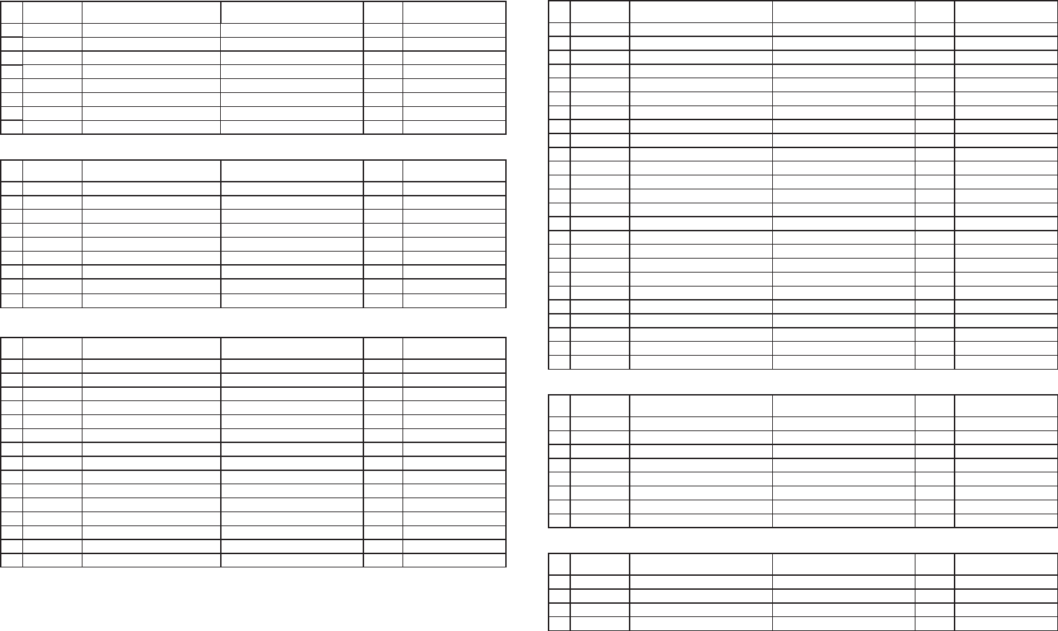
Addendum
Description de la borne
MIC (Prise modulaire)
N° de
broche
Nom de broche
Description Caractéristiques E/S Remarques
1 NC Non utilisé Non utilisé −
2 SB Puissance développée 13,8 V S
3 GND GND (terre) GND (terre) −
4 PTT Signal PTT (poussez-pour-parler) Impédance entrée 100 kΩE
5 MICG MIC GND MIC GND −
6 MIC Entrée MIC 600
ΩE
7 HOOK Détection de support Impédance entrée 100 kΩE
8 NC Non utilisé Non utilisé −
CONNECTEUR COM (D-SUB 9 broches)
N° de
broche
Nom de broche
Description Caractéristiques E/S Remarques
1 CD Détection de porteuse Conforme au standard RS-232C E
2 RD Réception de données Conforme au standard RS-232C E
3 SD Emission de données Conforme au standard RS-232C S
4 DTR Terminal de données prêt Conforme au standard RS-232C S
5 SG GND (terre) GND (terre) −
6 DSR Poste de données prêt Conforme au standard RS-232C E
7 RTS Demande pour émettre Conforme au standard RS-232C S
8 CTS Voie libre Conforme au standard RS-232C E
9 CI Tonalité DET Conforme au standard RS-232C E
CONNECTEUR TEST/MICROPHONE
N° de
broche
Nom de broche
Description Caractéristiques E/S Remarques
1 SB Puissance développée 13,8 V S
2 SB Puissance développée 13,8 V S
3 NC Non utilisé Non utilisé −
4 GND GND (terre) GND (terre) −
5 GND GND (terre) GND (terre) −
6 SPG Haut parleur GND Haut parleur GND −
7 RD RX Sortie Audio Impédance de charge 4,7 kΩS pas de désaccentuation
8 RSSI RSSI Sortie signal Niveau de sortie 0 à 5 V S
9 SPI Entrée haut parleur interne Court avec "SPO" E
10 AO1 Borne de collecteur ouvert Valeur de courant admissible 200mA S
11 AO2 Borne de collecteur ouvert Valeur de courant admissible 200mA S
12 SPO Sortie haut parleur externe Niveau de sortie 3W (Distorsion 5%) S
13 AO3 Borne de collecteur ouvert Valeur de courant admissible 200mA S
14 AO4 Borne de collecteur ouvert Valeur de courant admissible 200mA S
15 AO5 Borne de collecteur ouvert Valeur de courant admissible 200mA S
CONNECTEUR Commande E/S (D-SUB 25 broches)
N° de
broche
Nom de broche
Description Caractéristiques E/S Remarques
1 NC Non utilisé Non utilisé −
2 NC Non utilisé Non utilisé −
3 NC Non utilisé Non utilisé −
4 AI1 Entrée fonction programmable 1 Impédance entrée 47 kΩE
5 AI2 Entrée fonction programmable 2 Impédance entrée 47 kΩE
6 AI3 Entrée fonction programmable 3 Impédance entrée 47 kΩE
7 DG GND numérique GND numérique −
8 TD TX Entrée audio Impédance entrée 600 ΩE pas de pré-accentuation
9 TA TX Entrée audio Impédance entrée 600 ΩE Pré-accentuation
10 RD RX Sortie Audio Impédance de charge 4,7 kΩS pas de désaccentuation
11 RA RX Sortie Audio Impédance de charge 4,7 kΩS Désaccentuation
12 RXG GND Signal RX GND Signal RX −
13 SPM Haut parleur en sourdine Impédance entrée 47 kΩE
14 BER CLK
Pour l'horloge des taux d'erreur sur les bits
CMOS S
15 EMON Commutateur de moniteur externe Impédance entrée 47 kΩE
16 EPTT Commutateur PTT externe Impédance entrée 47 kΩE
17 SC Commande du silencieux Niveau de sortie 0 ou 3,3 V S
18 BER DAT
Pour les données des taux d'erreur sur les bits
CMOS S
19 TXG GND Signal de transmission GND Signal de transmission −
20 IO1 Fonction programmable E/S 1 Impédance entrée 47 kΩE/S Niveau de sortie 0 ou 5 V
21 IO2 Fonction programmable E/S 2 Impédance entrée 47 kΩE/S Niveau de sortie 0 ou 5 V
22 IO3 Fonction programmable E/S 3 Impédance entrée 47 kΩE/S Niveau de sortie 0 ou 5 V
23 IO4 Fonction programmable E/S 4 Impédance entrée 47 kΩE/S Niveau de sortie 0 ou 5 V
24 IO5 Fonction programmable E/S 5 Impédance entrée 47 kΩE/S Niveau de sortie 0 ou 5 V
25 IO6 Fonction programmable E/S 6 Impédance entrée 47 kΩE/S Niveau de sortie 0 ou 5 V
LAN (Prise modulaire)
N° de
broche
Nom de broche
Description Caractéristiques E/S Remarques
1 TD+ Signal + TX Comforme au standard IEEE802.3 S 100 Mbps
2 TD- Signal − TX Comforme au standard IEEE802.3 S 100 Mbps
3 RD+ Signal + RX Utiliser le transformateur désigné E 100 Mbps
4 NC Non utilisé Non utilisé −
5 NC Non utilisé Non utilisé −
6 RD- Signal − RX Utiliser le transformateur désigné E 100 Mbps
7 NC Non utilisé Non utilisé −
8 NC Non utilisé Non utilisé −
Connecteurs SYNC 1, 2 (Il y a deux connecteurs)
N° de
broche
Nom de broche
Description Caractéristiques E/S Remarques
1 FRMA Signal Différentiel A RS-485 Conforme au RS485 E/S
2 NC Non utilisé Non utilisé −
3 NC Non utilisé Non utilisé −
4 FRMB Signal Différentiel B RS-485 Conforme au RS485 E/S
RX ANT Impédance 50
Ω
TX ANT Impédance 50
Ω
REF IN Entrée signal de référence externe (10 MHz). Impédance : supérieure à 1 kΩ
REF OUT Distribution signal de référence (10 MHz). Impédance de charge : supérieure à 20 Ω
B59-2539-00
B59-2539-00_NXR-700-800_French.iA AB59-2539-00_NXR-700-800_French.iA A 2008/02/21 10:18:292008/02/21 10:18:29
MANDATORY SAFETY INSTRUCTIONS TO INSTALLERS AND USERS
• Use only manufacturer or dealer supplied antennas.
• Antenna Minimum Safe Distance: 180 cm (6 feet).
• Antenna Gain: 0 dBd referenced to a dipole.
The Federal Communications Commission has adopted a safety standard
for human exposure to RF (Radio Frequency) energy which is below the
OSHA (Occupational Safety and Health Act) limits.
• Antenna Mounting: The antenna supplied by the manufacturer or
radio dealer must not be mounted at a location such that during radio
transmission, any person or persons can come closer than the above
indicated minimum safe distance to the antenna, i.e. 180 cm (6 feet).
• To comply with current FCC RF Exposure limits, the antenna must be
installed at or exceeding the minimum safe distance shown above,
and in accordance with the requirements of the antenna manufacturer
or supplier.
• Vehicle installation: The antenna can be mounted at the center
of a vehicle metal roof or trunk lid, if the minimum safe distance is
observed.
• Base Station Installation: The antenna should be xed-mounted on
an outdoor permanent structure. RF Exposure compliance must be
addressed at the time of installation.
Antenna substitution: Do not substitute any antenna for the one supplied
or recommended by the manufacturer or radio dealer.
You may be exposing person or persons to excess radio frequency
radiation. You may contact your radio dealer or the manufacturer for
further instructions.
Maintain a separation distance from the antenna to person(s) of at
least 180 cm (6 feet).
You, as the qualied end-user of this radio device must control the
exposure conditions of bystanders to ensure the minimum separation
distance (above) is maintained between the antenna and nearby persons
for satisfying RF Exposure compliance. The operation of this transmitter
must satisfy the requirements of Occupational/Controlled Exposure
Environment, for work-related use, transmit only when person(s) are at
least the minimum distance from the properly installed, externally mounted
antenna. Transmit only when people outside the vehicle are at least the
recommended minimum lateral distance away from the antenna/vehicle.
B59-2667-00