Japan Radio Co NKE1125 Marine Radar User Manual JMA 9100 series RADAR Instruction Manual
Japan Radio Co Ltd. Marine Radar JMA 9100 series RADAR Instruction Manual
Contents
- 1. Users Manual 1
- 2. Users Manual 2
- 3. Users Manual 3
Users Manual 1

MARINE RADAR EQUIPMENT
INSTRUCTION MANUAL
JMA-9133-SA JMA-9132-SA
JMA-9123-7XA/9XA
JMA-9122-6XA/9XA/6XAH
JMA-9110-6XA/6XAH
MARINE RADARMARINE RADAR
EQUIPMENTEQUIPMENT
INSTRUCTIONINSTRUCTION
MANUALMANUAL
JMA-9133-SAJMA-9133-SA
JMA-9132-SAJMA-9132-SA
JMA-9123-7XA/9XAJMA-9123-7XA/9XA
JMA-9122-6XA/9XA/6XAHJMA-9122-6XA/9XA/6XAH
JMA-9110-6XA/6XAHJMA-9110-6XA/6XAH
01ETM ISO 9001, ISO 14001 Certified
Printed in Japan
Marine Service Department
+81-3-3492-1305
+81-3-3779-1420
tmsc@jrc.co.jp
Telephone :
Facsimile :
e-mail :
AMSTERDAM Branch
Telephone :
Facsimile :
e-mail :
+31-20-658-0750
+31-20-658-0755
service@jrcams.nl
SEATTLE Branch
Telephone :
Facsimile :
e-mail :
+1-206-654-5644
+1-206-654-7030
service@jrcamerica.com
CODE No.7ZPRD0685CODE No.7ZPRD0685
MAR. 2008 Edition 1 JRCMAR. 2008 Edition 1 JRC
Not use the asbestos
For further information,contact:
URL http://www.jrc.co.jp
i
◆◆◆ PRECAUTIONS BEFORE OPERATION ◆◆◆
■Cautions for high voltage
High voltages from hundreds volts to tens of thousands volts are to be applied to
the electronic equipment such radio and radar devices. You do not face any
danger during normal operation, but sufficient cares are required for maintenance,
inspection and adjustment of their internal components. (Maintenance, check-up
and adjustment of the inside of the equipment are prohibited except by
maintenance specialists.)
High voltages of tens of thousands volts are so dangerous as to bring an
instantaneous death from electric shock, but even voltages of hundred volts may
sometimes lead to a death from electric shock. To prevent such an accident, make
it a rule to turn off the power switch, discharge capacitors with a wire surely
earthed on an end make sure that internal parts are no longer charged before you
touch any parts inside these devices. At the time, wearing dry cotton gloves
ensures you further to prevent such danger. It is also a necessary caution to put
one of your hands in the pocket and not to use your both hands at the same time.
It is also important to select a stable foothold always to prevent additional injuries
once you were shocked by electricity. If you were injured from electric shock,
disinfect the burn sufficiently and get it taken care of promptly.
■What to do in case of electric shock
When finding a victim of electric shock, turn off the power source and earth the
circuit immediately.
If it is impossible to turn off the circuit, move the victim away promptly using
insulators such as dry wood plate and cloth without touching the victim directly.
In case of electric shock, breathing may stop suddenly if current flows to the
respiration center in the brain. If the shock is not so strong, artificial respiration
may recover breathing. When shocked by electricity, the victim will come to look
very bad with weak pulse or without beating, resulting in unconsciousness and
rigidity. In this case, it is necessary to perform an emergency measure
immediately.
ii
◆◆◆ FIRST-AID TREATMENTS ◆◆◆
☆First-aid treatments
As far as the victim of electric shock is not in dangerous condition, do not move
him and practice artificial respiration on him immediately. Once started, it should
be continued rhythmically.
(1) Do not touch the victim confusedly as a result of the accident, but the
rescuer may also get an electric shock.
(2) Turn off the power source calmly and move the victim away quietly from
the electric line.
(3) Call a physician or ambulance immediately or ask someone to call a doctor.
(4) Lay the victim on this back and loosen his necktie, clothes, belt, etc.
(5)
a. Examine the victim's pulse.
b. Examine his heartbeat bringing your ear close to his heart.
c. Examine his breathing bringing the back of your hand or your face
close to his face.
d. Check the size of the pupils of his eyes.
(6) Open the victim's mouth and take out artificial teeth, cigarette or chewing
gum if any. Keep his mouth open, stretch his tongue and insert a towel or
the like in his mouth to prevent the tongue from suffocating. (If it is hard to
open his mouth due to set teeth, open it with a screwdriver and insert a towel
in this mouth.)
(7) Then, wipe his mouth so that foaming mucus does not accumulate inside.
iii
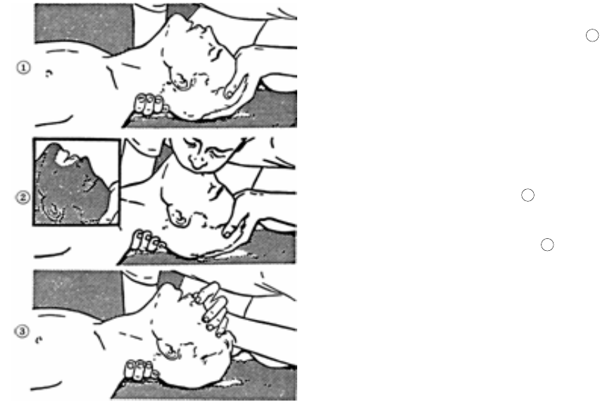
☆When pulse is beating but breathing has stopped
(Mouth-to-mouth respiration) Fig 1.
(1) Tilt the victim's head back as far as this face looks back. (A pillow may be
inserted his neck.)
(2) Push his jaw upward to open his throat wide (to spread his airway).
(3) Pinch the victim's nostrils and take a deep breath, block his mouth
completely with yours and blow into his mouth strongly. Take a deep breath
again and blow into his mouth. Continue this 10 to 15 times a minutes
(blocking his nostrils).
(4) Carefully watch that he has recovered his natural breathing and atop
practicing artificial respiration.
(5) If it is difficult to open the victim's mouth, insert a rubber or vinyl tube into
one of his nostrils and blow into it blocking the other nostril and his mouth
completely.
(6) When the victim recovers consciousness, he may try to stand up suddenly,
but let him lie calmly and serve him with a cup of hot coffee or tea and keep
him warm and quiet. (Never give him alcoholic drinks.)
Method of mouth-to-mouth respiration by raising hea
Fig 1. Mouth-to mouth respiration
(1)Raise the victim's head. Support
his forehead with one of your hand
and his neck with the other hand.
When you tilt his head backward, the
victim, in most cases, opens his
mouth to the air. This makes mouth-
to mouth respiration easy.
(2)Cover his mouth as widely as
possible with yours and press your
cheek against his nose
or, pinch his nostrils with your fingers
to prevent air from leaking.
(3)Blow into his lungs. Continue
blowing into his mouth until his breast
swells. Blow into his mouth as quickly
as possible for the first 10 times.
1
2
3
iv
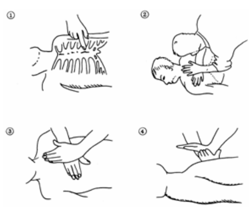
☆When both pulse and breathing have stopped
Perform the (Cardiac massage) Fig 2. and (Mouth-to-mouth respiration) Fig 1.
When no pulse has come not to be felt, his pupils are open and no heartbeat is
heard, cardiac arrest is supposed to have occurred and artificial respiration must
be performed.
(1) Place your both hands, one hand on the other, on the lower one third area of
his breastbone and compress his breast with your elbows applying your
weight on his breast so that it is dented about 2cm (Repeat compressing his
breast 50 times or so a minutes). (Cardiac massage)
(2) In case of one rescuer,
Repeat cardiac massages about 15 times and blow into his mouth 2 times
quickly, and repeat this combination.
In case of two rescuers,
One person repeats cardiac massages 15 times while the other person blow
into his mouth twice, and they shall repeat this combination. (Perform the
cardiac massage and mouth-to-mouth respiration)
(3) Examine his pupils and his pulse sometimes. When the both have returned
to normal, stop the artificial respiration, serve him with a cup of hot coffee
or tea and keep him warm and calm while watching him carefully. Commit
the victim to a medical specialist depending on his condition. (Never give
him alcoholic drinks.) To let him recover from the mental shock, it is
necessary for persons concerned to understand his situations and the
necessary treatment.
Fig 2. Cardiac massage
v
PREFACE
Thank you very much for purchasing the JRC marine radar equipment, JMA-9100
series.
This equipment is a marine radar equipment designed to obtain safe operation of
marine ships.
This equipment consists of a radar signal transmitter-receiver unit, a LCD display
unit and a scanner unit as its main units.
•Before operating the equipment, be sure to read this instruction manual
carefully for correct operation.
•Maintain this instruction manual so that operators can refer to it at anytime.
Refer to this manual when any inconvenience or defect occurs.
vi
●Before Operation ●
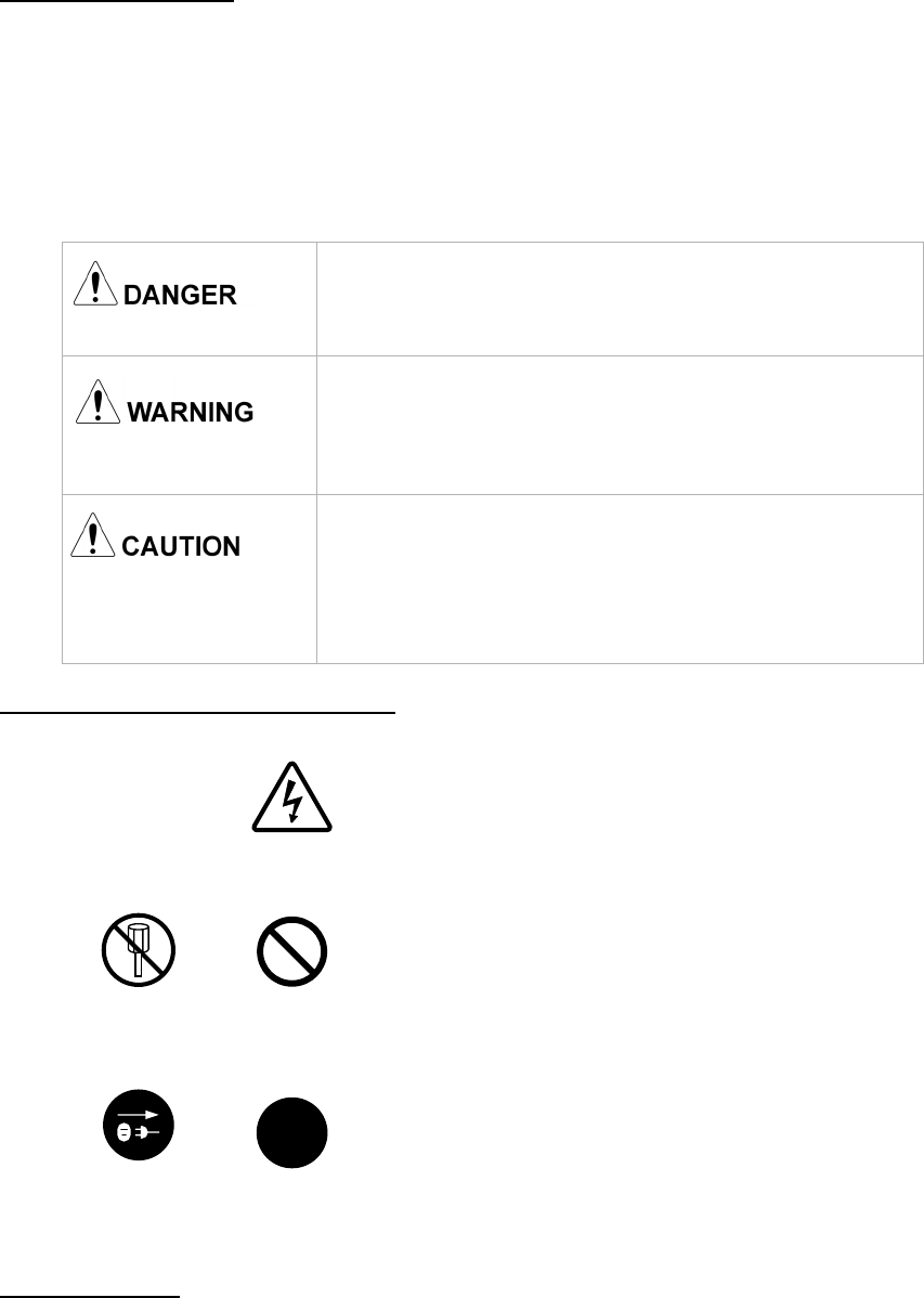
Pictorial Indication
Various pictorial indications are included in this manual and are shown on these
equipment so that you can operate them safety and correctly and prevent any
danger to you and/or to other persons and any damage to your property during
operation. Such indications and their meanings are as follows.
Please understand them before you read this manual:
Examples of Pictorial Indication
Warning Label
There is a warning label on the top cover of the equipment.
Do not try to remove, break or modify the label.
This indication is shown where incorrect
equipment operation due to negligence may
cause death or serious injuries.
This indication is shown where any person is
supposed to be in danger of being killed or
seriously injured if this indication is neglected
and these equipment are not operated correctly.
This indication is shown where any person is
supposed to be injured or any property damage
is supposed to occur if this indication is
neglected and these equipment are not
operated correctly.
Electric Shock
The △ mark represents CAUTION (including DANGER and
WARNING).Detailed contents of CAUTION ("Electric
Shock" in the example on the left.) is shown in the mark.
Disassembling
Prohibited
Prohibited
The mark represents prohibition. Detailed contents of the
prohibited action (“Disassembling Prohibited” in the example
on the left.) is shown in the mark.
Disconnect the
power plug Instruction
The mark represents instruction.
Detailed contents of the instruction (“Disconnect the power
plug “ in the example on the left.) is shown in the mark.
!
vii
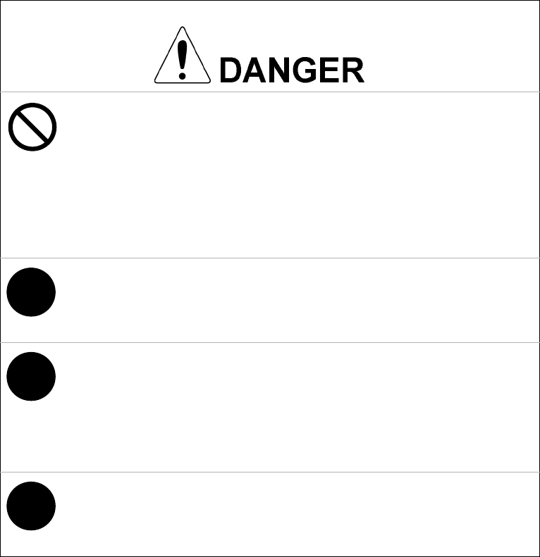
●PRECAUTIONS ●
Never conduct inspection or repair work of equipment
components.
Inspection or repair work by uncertified personnel may
result in fire hazard or electrocution.
For inspection and repair work of equipment
components, consult with our branch office, branch
shop, sales office, or our distributor in your district.
!
When conducting maintenance, make sure to turn the
main power off.Failure to comply may result in
electrocution.
!
Turn off the main power before cleaning the equipment.
Especially when a rectifier is used, make sure to turn it
off since voltage is still outputted from the rectifier even
after the indicator and the radar are turned off. Failure to
comply may result in equipment failure, or death or
serious injury due to electric shock.
!
When conducting maintenance work on the scanner,
make sure to turn its main power off.Failure to comply
may result in electrocution or injuries.
viii
!
Make sure to turn off the scanner safety switch. Failure to
comply may result in injuries caused by physical contact
with the rotating scanner.
Never directly touch the internal components of the
scanner or indicator. Direct contact with these high-
voltage components may cause electrocution. For
maintenance, inspection, or adjustment of equipment
components, consult with our branch office, branch
shop, sales office, or our distributor in your district.
To contact our sales department, branch offices, branch
shops, and sales offices:
Please refer to the "Office List" at the end of the
document.
Do not get close to the radiant section of the scanner. It
is a rotating part, and it may cause injuries if it suddenly
starts rotating and consequently hits the body. It is
recommended that the radiant section be installed at a
high place such as on the roof of the wheelhouse, on the
flying bridge, on the trestle, or on the radar mast so that
no one can get close to it. When any work must be done
on the scanner, make sure to turn the safety switch off.

ix
Microwave radiation level:
Keep out from a distance closer than that specified below
for each type of scanner when it is transmitting. Being
within the specified distance from the center of the front
face of the scanner may cause microwave exposure
which could result in injuries (especially of the eyes).
NKE-2103 (radiation levels: 10 W/m2): 0.6 m
NKE-2254 (radiation levels: 10 W/m2): 0.6 m
NKE-1125/1129 (radiation levels: 10 W/m2): 0.7m
NKE-1130/1139 (radiation levels: 10 W/m2): 1.1 cm
!
Make sure to install the scanner at a place higher than
human height.
Direct exposure to electromagnetic waves at close range
will have adverse effects on the human body.
!
Direct exposure to electromagnetic waves at close range
will have adverse effects on the human body. When it is
necessary to get close to the scanner for maintenance or
inspection purposes, make sure to turn the indicator
power switch to "OFF" or "STBY."
Direct exposure to electromagnetic waves at close range
will have adverse effects on the human body.
!
When conducting maintenance work, make sure to turn
off the power so that the power supply to the equipment
is completely cut off.
Some equipment components can carry electrical current
even after the power switch is turned off, and conducting
maintenance work without unplugging the power
connector may result in electrocution, equipment failure,
or accidents.
x
When cleaning the display screen, do not wipe it too
strongly with a dry cloth. Also, do not use gasoline or
thinner to clean the screen. Failure to comply will result
in damage to the screen surface.
!
Do not change MBS Level/Area unless absolutely
necessary.
Incorrect adjustment will result in deletion of nearby
target images and thus collisions may occur resulting in
death or serious injuries.
!
When disposing of used lithium batteries, be sure to
insulate the batteries by attaching a piece of adhesive
tape on the + and - terminals. Failure to comply may
cause heat generation, explosion, or fire when the
batteries get shorted out.
!
Use the radar only as a navigation aid. The final
navigation decision must always be made by the
operator him/herself. Making the final navigation decision
based only on the radar display may cause accidents
such as collisions or running aground.
xi
!
Use Target Tracking (TT) function only as a navigation
aid. The final navigation decision must always be made
by the operator him/herself. Making the final navigation
decision based only on tracking target information may
cause accidents.
Tracking target information such as vector, target
numerical data, and alarms may contain some errors.
Also, targets that are not detected by the radar cannot be
acquired or tracked.
Making the final navigation decision based only on the
radar display may cause accidents such as collisions or
running aground.
!
A malfunction may occur if the power in the ship is
instantaneously interrupted during operation of the radar.
In this case, the power should be turned on again.
When using the [AUTO SEA] function, never set the
suppression level too high canceling out all image noises
from the sea surface at close range.
Detection of not only echoes from waves but also targets
such as other ships or dangerous objects will become
inhibited.
When using the [AUTO SEA] function, make sure to
choose the most appropriate image noise suppression
level.
When using the [AUTO RAIN] function, never set the
suppression level too high canceling out all image noises
from the rain or snow at close range.
Detection of not only echoes from the rain or snow but
also targets such as other ships or dangerous objects
will become inhibited.
When using the [AUTO RAIN] function, make sure to
choose the most appropriate image noise suppression
level.

xii
!
When setting a guard zone, make sure to properly adjust
gain, sea-surface reflection suppression level, and rain/
snow reflection suppression level so that the optimal
target images are always on the radar screen. The guard
zone alarm will not be activated for targets undetected by
the radar, and it may result in accidents such as
collisions.
!
The simulation function is used exclusively for deciding
whether or not target tracking is properly operating.
Therefore, never use this function unless you wish to
check target tracking operations.
Note especially that, if this function is used during actual
navigation, simulated targets are displayed and may
become confused with other actual targets. Therefore,
never use this function during actual navigation.
Optimal values have been set for VD LEVEL and
CONSTANT; therefore, never change their values unless
absolutely necessary. Failure to comply may result in
accidents that would lower target tracking performance.
Make sure to shut off the main power before replacing
parts. Failure to comply may result in electrocution or
equipment failure.
!
When replacing magnetrons, make sure to shut off the
main power and let the equipment stand for more than 5
minutes to discharge the high-voltage circuit. Failure to
comply may result in electrocution.
xiii
!
Make sure to take off your watch when your hand must
get close to the magnetron.
Failure to comply may result in damage to the watch
since the magnetron is a strong magnet.
!
Make sure that two or more staff member work together
when replacing the LCD. If only one person attempts to
replace the LCD, he/she may drop it and become injured.
Do not directly touch the inverter circuit of the LCD
display with a bare hand since high voltage temporarily
remains in the circuit even after the main power is shut
off.
Failure to comply may result in electrocution.
Any adjustments must be made by specialized service
personnel.
Incorrect settings may result in unstable operation.
Do not make any adjustments during navigation. Failure
to comply may result in adverse effects on the radar
function which may lead to accidents or equipment
failure.
Any adjustments must be made by specialized service
personnel.
Failure to comply may result in accidents or equipment
failure.
Do not make any adjustments during navigation. Failure
to comply may result in adverse effects on the radar
function which may lead to accidents or equipment
failure.
xiv
Do not change the quantization level settings unless
absolutely necessary. If set at an inappropriate value, the
target acquisition or target tracking function deteriorates,
and this may lead to accidents.
xv
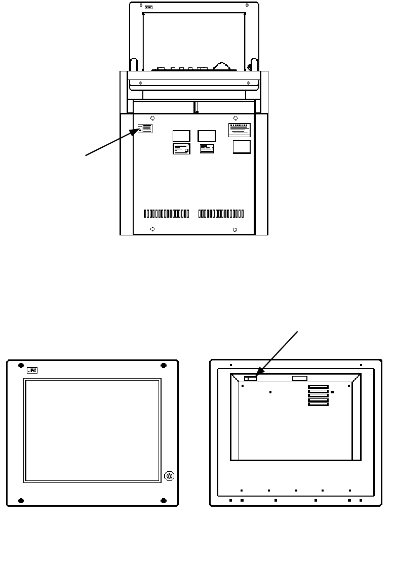
The Mounting Point of the Warning Label
NWZ-170 Monitor Unit
NCD-4990 Display Unit
Warning Label
Warning Label
Front face Back face
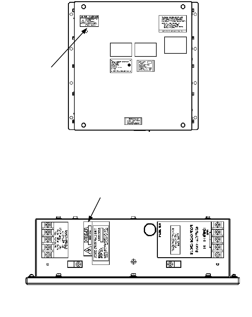
xvi
NBA-5135 AC/DC Converter
(Desktop Type)
NDC-1399-9 Radar Process Unit
(Desktop Type)
Warning Label
Warning Label
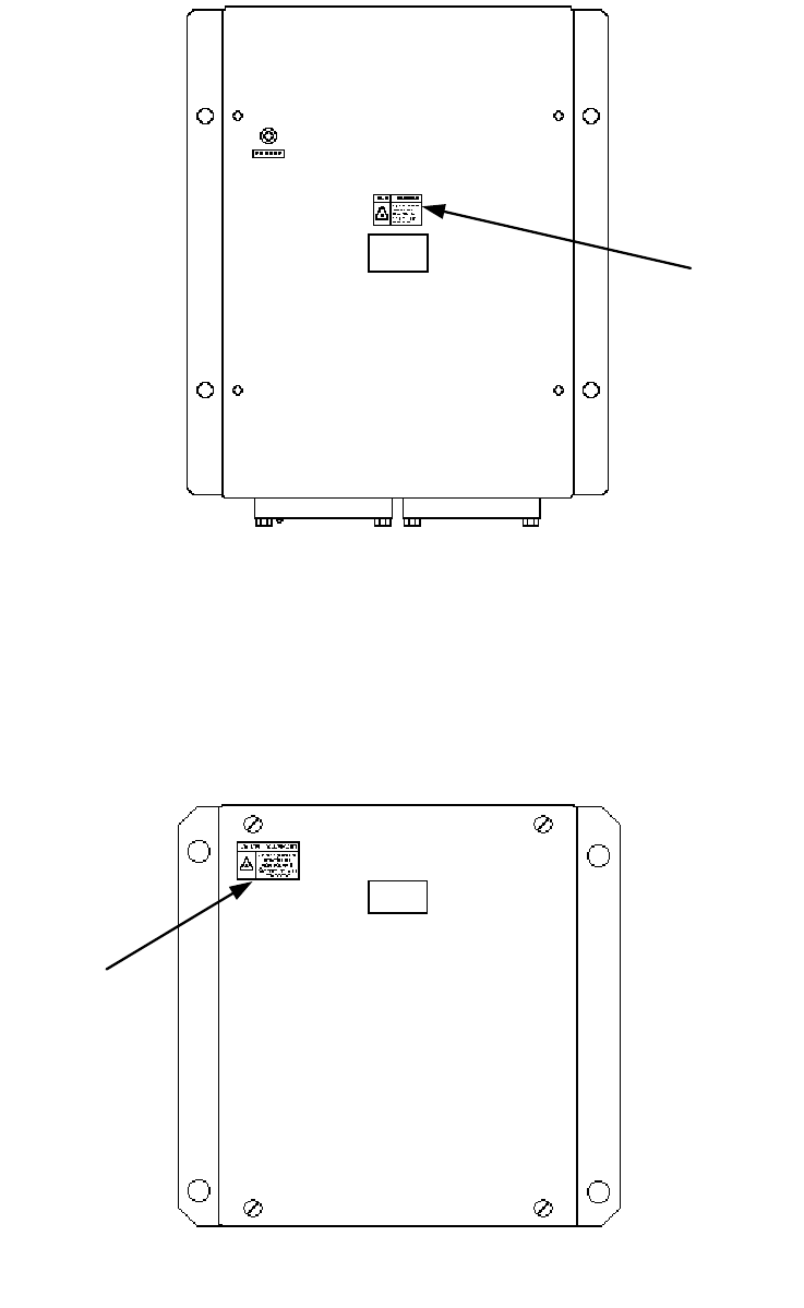
xvii
NQE-3141-4A/8A Interswitch Unit
NQE-3167 Power Control Unit
Warning
Label
Warning
Label
xviii
NKE-2103-6/6HS Scanner Unit
NKE-1129-7/9 Scanner Unit
NKE-1125-6/9 Scanner Unit
NKE-2254-6HS Scanner Unit
Warning L
a
Warnin
g
xix
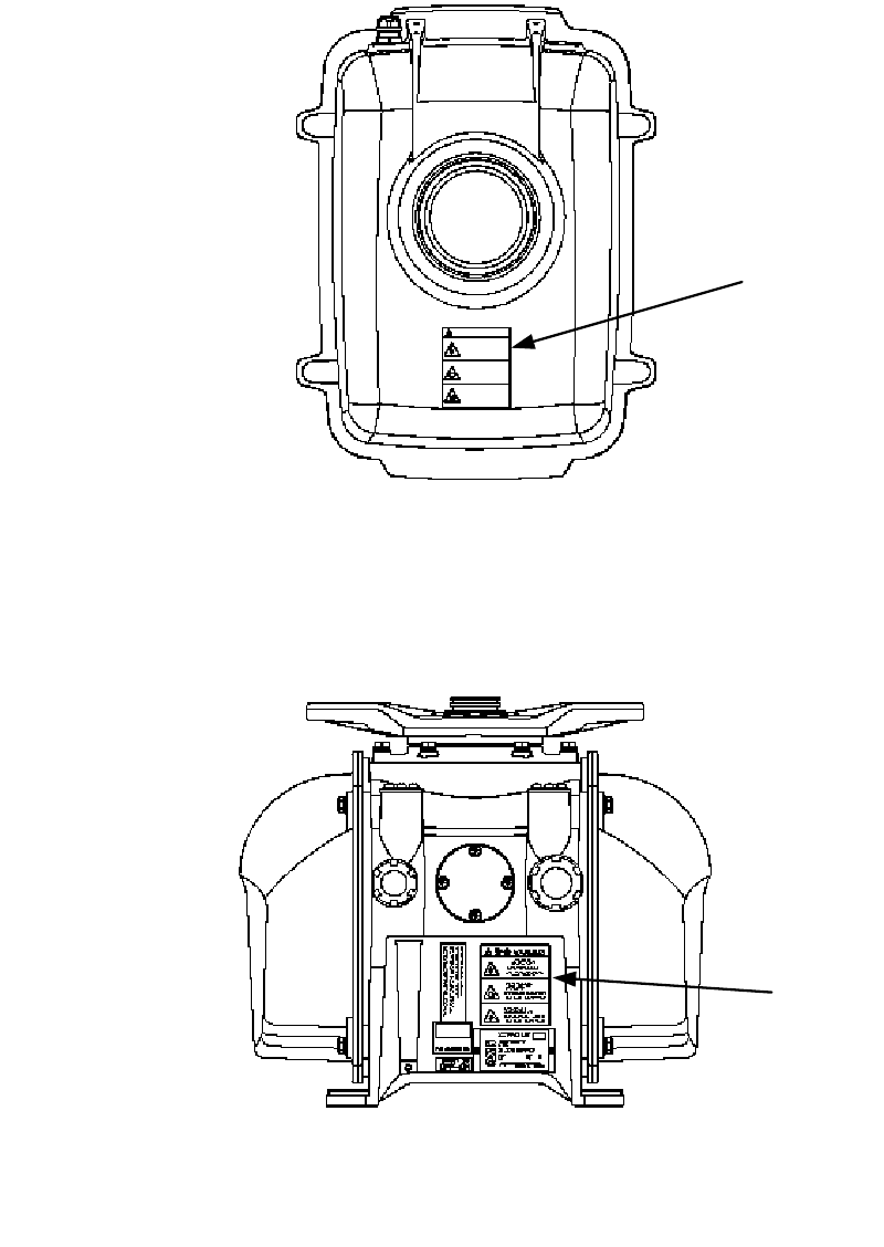
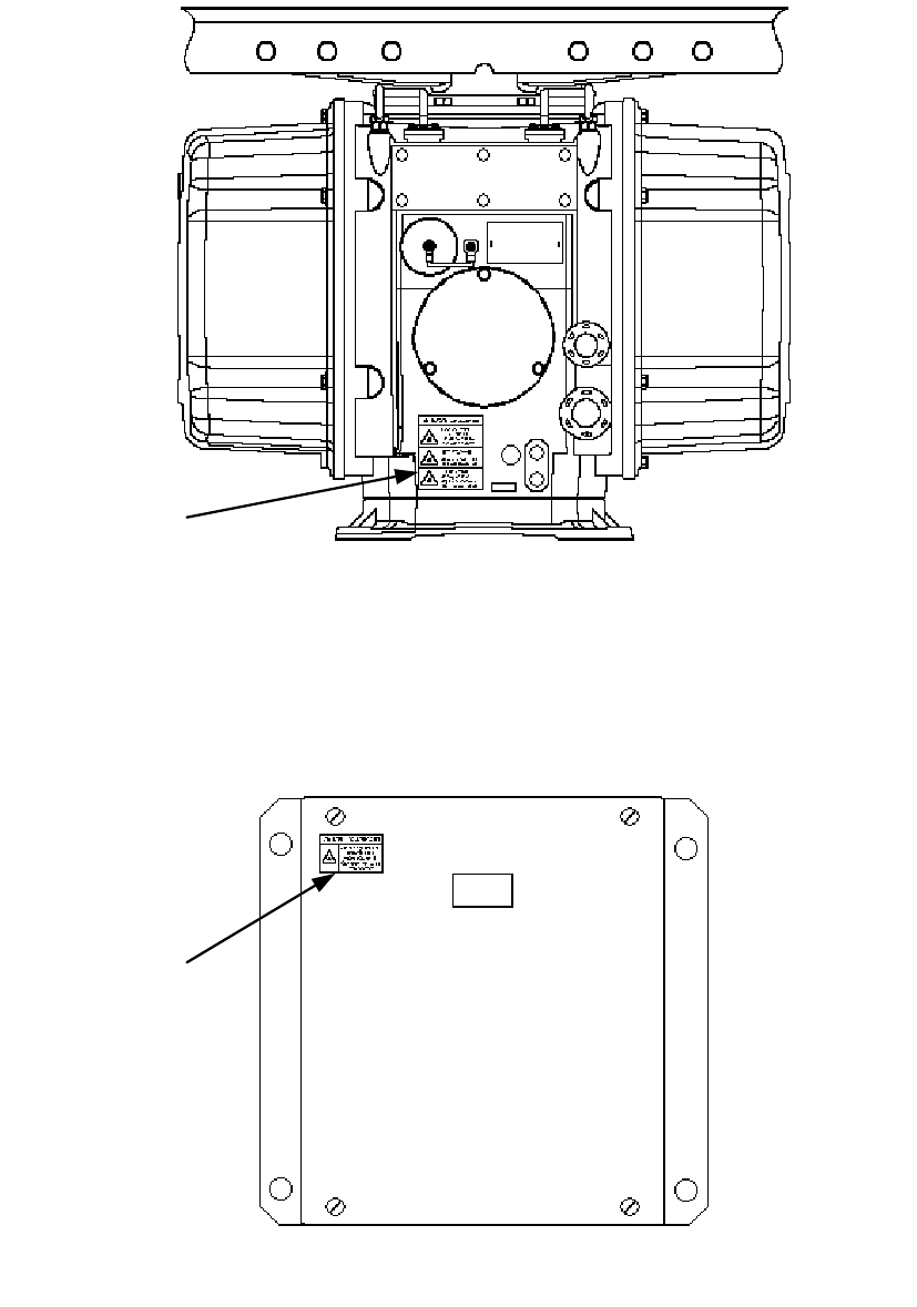
NKE-1139/1130 Scanner Unit
NTG-3230/3225 Transmitter Receiver Unit
Warning Label
Warning Label
xx
EQUIPMENT APPEARANCE
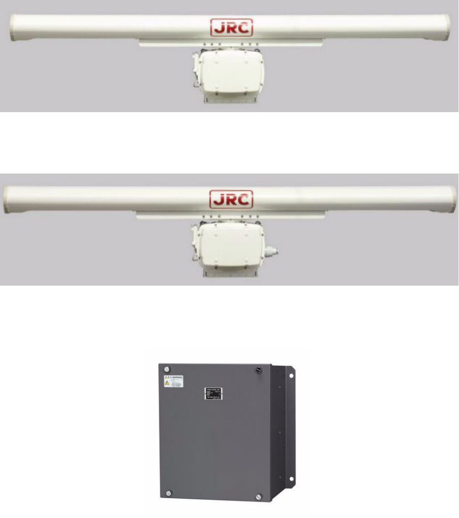
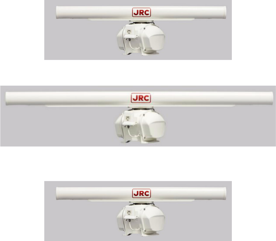
Scanner Unit Type NKE-1130 (12 feet)
Scanner Unit Type NKE-1139 (12 feet)
Transmitter Receiver Unit Type NTG-3230(30kW)
xxi
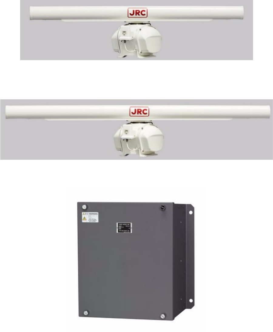
Scanner Unit Type NKE-1129-7 (7 feet)
Scanner Unit Type NKE-1129-9 (9 feet)
Transmitter Receiver Unit Type NTG-3225(25kW)
xxii
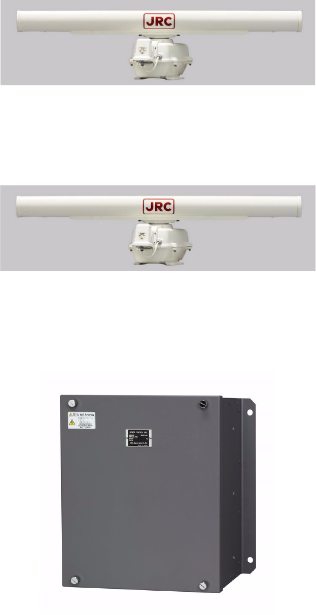
Scanner Unit Type NKE-1125-6 (6 feet)
Scanner Unit Type NKE-1125-9 (9 feet)
Scanner Unit Type NKE-2254-6HS (6 feet)
xxiii
Scanner Unit Type NKE-2103-6 (6 feet)
Scanner Unit Type NKE-2103-6HS (6 feet)
Power Control Unit Type NQE-3167
xxiv
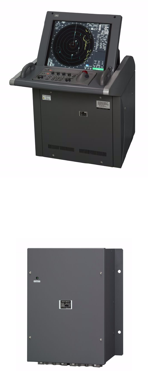
Display Unit Type NCD-4990 (Stand alone type)
Interswitch Unit Type NQE-3141-4A
xxv
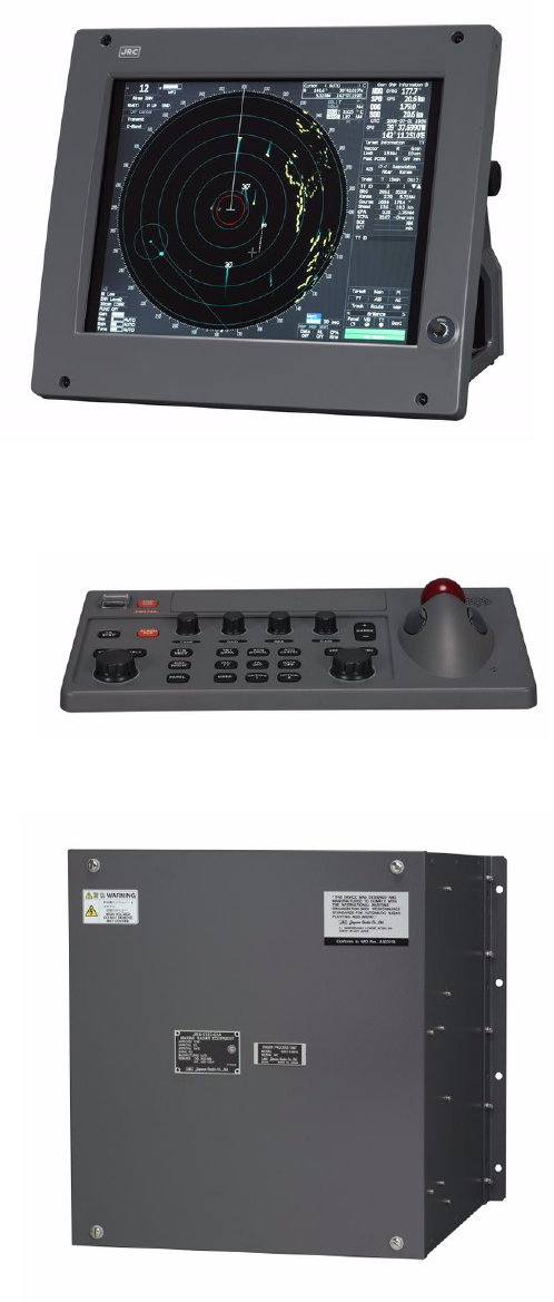
Monitor Unit Type NWZ-170 (Desktop type)
Operation Unit Type NCE-5163 (Desktop type)
Radar Process Unit Type NDC-1399-9 (Desktop type)
DISPLAY UNIT TYPE NCD-4990T (DESKTOP TYPE)

xxvi
GLOSSARY
This section describes the main terms used for this equipment and general related
maritime terms.
A
AZ Acquisition/Activation zone
A zone set up by the operator in which the system should
automatically acquire radar targets and activate reported AIS targets
when entering the zone.
Activated target A target representing the automatic or manual activation of a
sleeping target for the display of additional information.
AIS Automatic Identification System
A system which enables ships and shore stations to obtain
identifying and navigation information about other ships at sea,
using an automated transponder.
Anti-clutter rain Rain/snow clutter suppression.
Anti-clutter sea Sea clutter suppression.
Associated target A target simultaneously representing a tracked target and a reported
AIS target having similar parameters (position, course, speed)
which comply with an association algorithm.
AZI AZImuth stabilization mode
B
BCR/BCT Bow Crossing Range/Bow Crossing Time
C
C up Course up
Own ship's course is pointed to the top center of the radar display.
CCRP Consistent Common Reference Point
A location on own ship, to which all horizontal measurements such
as target range, bearing, relative course, relative speed, CPA or
TCPA are referenced, typically the conning position of the bridge.
Clutter Unwanted reflections on a radar screen, from sea surface, rain or
snow.
COG Course Over Ground
The direction of the ship's movement relative to the earth, measured
on board the ship, expressed in angular units from true north
CORREL CORRELation

xxvii
CPA/TCPA The distance to the Closest Point of Approach/Time to the Closest
Point of Approach.
Limits are set by the operator and are related to own ship.
CTW Course Through Water
The direction of the ship's movement through the water
D
DRIFT The current velocity for manual correction or the current speed on
the horizontal axis of the 2-axis log is displayed.
E
EBL Electronic Bearing Line
An electronic bearing line originated from own ship's position.
ETA Estimated Time of Arrival
G
Ground
stabilization
A display mode in which speed and course information are referred
to the ground, using ground track input data.
H
HDG Heading
The horizontal direction that the bow of a ship is pointing at any
instant, expressed in angular units from a reference direction.
HL Heading line
A graphic line on a radar presentation drawn from the consistent
common reference point to the bearing scale to indicate the heading
of the ship .
HSC High Speed Craft
Vessels which comply with the definition in SOLAS for high speed
craft
H up Head up
Own ship's heading line is always pointed to the top center of the
radar display.
I
IMO International Maritime Organisation
IR RADAR Interference Rejector
ISW A device to switch over two or more radar display units and two or
more scanners.
L

xxviii
Lost AIS target A target symbol representing the last valid position of an AIS target
before the reception of its data was lost, or its last dead-reckoned
position.
Lost tracked
target
One for which target information is no longer available due to poor,
lost or obscured signals.
LP Long Pulse
M
MMSI Maritime Mobile Service Identity
MOB Man OverBoard
MON Performance monitor
MP Medium Pulse
N
NM 1nm=1852m
N up North up
P
PI Parallel Index line
Past positions Equally time-spaced past position marks of a tracked or AIS target
and own ship.
POSN POSitioN
PRF Pulse Repetition Frequency
The number of radar pulses transmitted each second.
PROC PROCess
Radar signal processing function
R
Radar beacon A navigation aid which responds to the radar transmission by
generating a radar signal to identify its position and identity
Radar cross-
section
Radar cross-section of a target determines the power density
returned to the radar for a particular power density incident on the
target
Range Rings A set of concentric circles labeled by distance from CCRP.
Reference target A symbol indicating that the associated tracked stationary target is
used as a speed reference for the ground stabilisation
Relative speed The speed of a target relative to own ship's speed data
Relative vector A predicted movement of a target relative to own ship's motion

xxix
RM Relative Motion
A display on which the position of own ship remains fixed, and all
targets move relative to own ship.
RM(R) Relative Motion. Relative Trails.
RM(T) Relative Motion. True Trails.
ROT Rate Of Turn
Change of heading per time unit.
Route A set of waypoints.
RR Range Rings
S
SART Search And Rescue Transponder
Radar transponder capable of operating in the 9GHz band
Sea stabilization A display mode in which speed and course information are referred
to the sea.
Sea state Status of the sea condition due to the weather environment,
expressed as a sea state 0 for flat conditions with minimal wind, to
sea state 8 for very rough sea conditions.
SET The current direction for manual correction or the current speed on
the horizontal axis of the 2-axis log is displayed.
Sleeping AIS
target
A target indicating the presence and orientation of a vessel
equipped with AIS in a certain location.
SOG Speed Over the Ground
The speed of the ship relative to the earth, measured on board of the
ship.
SP Short Pulse
STAB STABilization
STW Speed Through Water
The speed of the ship relative to the water surface.
T
TCPA Time to Closest Point of Approach to own ship
Test target Radar target of known characteristics used for test requirement
TM True Motion
A display across which own ship moves with its own true motion.
Trails Tracks displayed by the radar echoes of targets in the form of an
afterglow.

xxx
Trial manoeuvre A graphical simulation facility used to assist the operator to
perform a proposed maneuver for navigation and collision
avoidance purposes.
True course The direction of motion relative to ground or to sea, of a target
expressed as an angular displacement from north
True speed The speed of a target relative to ground, or to sea
True vector A vector representing the predicted true motion of a target, showing
course and speed with reference to the ground or sea
TT Target Tracking.
A computer process of observing the sequential changes in the
position of a radar target in order to establish its motion. Such a
target is a Tracked Target.
TTG Time To Go.
Time to next waypoint.
TXRX Transmitter Receiver Unit
U
UTC Universal Time Coordinated.
The international standard of time, kept by atomic clocks around
the world.
V
VRM Variable Range Marker
An adjustable range ring used to measure the distance to a target.
W
Waypoint A geographical location on a route indicating a event.

Index
◆◆◆ PRECAUTIONS BEFORE OPERATION ◆◆◆.............................................. i
◆◆◆ FIRST-AID TREATMENTS ◆◆◆.................................................................. ii
PREFACE ................................................................................................................... v
The Mounting Point of the Warning Label................................................................. xv
EQUIPMENT APPEARANCE ................................................................................... xx
GLOSSARY ............................................................................................................ xxvi
SECTION 1
GENERAL AND EQUIPMENT COMPOSITION
1.1 FUNCTIONS ...........................................................................................1-1
1.1.1 Function of This System .................................................................1-1
1.2 FEATURES .............................................................................................1-2
1.3 CONFIGURATION ..................................................................................1-4
1.4 EXTERIOR DRAWINGS .........................................................................1-6
1.5 GENERAL SYSTEM DIAGRAMS ........................................................1-26
SECTION 2
NAMES AND FUNCTIONS OF CONTROL PANEL KEYS AND FUNCTIONS OF SOFTWARE BUTTONS
2.1 NAMES OF DISPLAY .............................................................................2-1
2.2 NAMES AND FUNCTIONS OF CONTROL PANEL KEYS ..................2-11
2.3 FUNCTIONS OF SOFTWARE BUTTONS ...........................................2-16
SECTION 3
BASIC OPERATION
3.1 OPERATION FLOW ...............................................................................3-1
3.1.1 Power ON and Start the System ....................................................3-2
3.1.2 Observe and Adjust Video ..............................................................3-4
3.1.3 Acquire and Measure Data .............................................................3-4
3.1.4 Display and Measure with Reference to CCRP ............................3-4
3.1.5 End the Operation and Stop the System .......................................3-5
3.2 OBSERVE AND ADJUST VIDEO ..........................................................3-6
3.2.1 Adjust Monitor Brilliance [BRILL] ..................................................3-6
3.2.2 Change Observation Range [RANGE+/-] ......................................3-6
3.2.3 Tune ..................................................................................................3-7
3.2.4 Adjust Gain [GAIN] .........................................................................3-8
3.2.5 Suppress Sea Clutter [SEA] ..........................................................3-9
3.2.6 Suppress Rain/Snow Clutter [RAIN] ...........................................3-11

3.2.7 Reset Alarm Buzzer [ALARM ACK] .............................................3-12
3.2.8 To get the appropriate image that targets can be easily observed ............3-13
3.3 OPERATION PROCEDURES ..............................................................3-14
3.3.1 Move Cross Cursor Mark by Trackball ........................................3-14
3.3.2 Operate Software Buttons ...........................................................3-15
3.3.3 Basic Menu Operation ..................................................................3-16
3.3.4 Operation on Numeric Value, Latitude / Longitude and Character Input menu .......3-17
3.3.5 Overview of Menu Structure .........................................................3-22
3.4 GENERAL RADAR OPERATION ........................................................3-23
3.4.1 Interference Rejection (IR) ............................................................3-23
3.4.2 Switch Transmitter Pulse Length [GAIN] ....................................3-24
3.4.3 Target Enhance (ENH) ..................................................................3-25
3.4.4 Use Video Processing (PROC) .....................................................3-26
3.4.5 Switch Azimuth Display Mode (AZI MODE) ................................3-27
3.4.6 Switch True/Relative Motion Display Mode (TM/RM) .................3-28
3.4.7 Move Own Ship’s Display Position (Off Center) .........................3-29
3.4.8 Display Radar Trails (Trails) .........................................................3-30
3.4.9 Zoom (x2) .......................................................................................3-33
3.4.10 Hide/Display Range Rings [HL OFF] ...........................................3-34
3.4.11 Hide Graphics Information on Radar Display [DATA OFF] .......3-34
3.4.12 Switch Day/Night Mode [DAY/NIGHT] .........................................3-35
3.4.13 Adjust Operation Panel Brilliance [PANEL] ................................3-35
3.4.14 Set True Bearing ............................................................................3-36
3.4.15 Set Own Ship Speed .....................................................................3-36
3.4.16 Magnet Compass Correction (MAG Compass Setting) .............3-37
3.5 USE OWN SHIP'S TRACK ...................................................................3-39
3.5.1 Display Own Ship’s Track (Display Own Track) .........................3-39
3.5.2 Set Display Color of Own Ship's Track (Display Own Track Color) ..3-40
3.5.3 Save Own Ship's Track (Own Track Memory) ............................3-41
3.5.4 Cancel Saving of Own Ship's Track (Own Track Memory) ........3-41
3.5.5 Clear Own Ship's Track (Clear Own Track) ................................3-42
3.5.6 Use Expanded Own Ship's Track (Own Track Type) .................3-42
3.5.7 Use Water Depth Track (Water Depth Track) ..............................3-44
3.5.8 Use Water Temperature Track (Water TEMP Track) ..................3-45
3.5.9 Use Tidal Current Track (Current Vector Track) .........................3-46

3.6 DISPLAY USER MAP ...........................................................................3-47
3.6.1 Create User Map (Mark/Line) ........................................................3-47
3.6.2 Set User Map Display (Mark Display Setting) .............................3-50
3.6.3 Edit User Map (Edit User Map) .....................................................3-52
3.6.4 Correct Position on User Map (Shift User Map) .........................3-60
3.6.5 Save User Map ...............................................................................3-61
3.6.6 Set and Display Geodetic System (Geodetic) .............................3-65
3.7 USE ROUTE FUNCTION ......................................................................3-67
3.7.1 Display Route/Destination Mark (Select Route) .........................3-67
3.7.2 Edit Route (Set Route Sequence) ................................................3-68
3.7.3 Edit Route Make with Latitude and Longitude (Waypoint Input) .......3-75
3.7.4 Use Route Monitoring Function (Waypoint/Route Alarm) .........3-79
3.7.5 Method of Using Route .................................................................3-81
3.7.6 Detailed Route Settings ................................................................3-82
3.7.7 Clear Waypoint/Route Data (Clear WPT/Route Data) .................3-86
3.7.8 Operate Route Data File ................................................................3-87
3.8 APPLIED OPERATIONS ......................................................................3-91
3.8.1 Set Radar Signal Processing (Process Setting) .........................3-91
3.8.2 Set Radar Trails (RADAR Trails Setting) .....................................3-95
3.8.3 Set Scanner Unit (TXRX Setting) .................................................3-97
3.8.4 Set Cursor (Cursor Setting) ..........................................................3-98
3.8.5 Set Radar Display (Display Setting) ............................................3-99
3.8.6 Adjust Sound Volume (Buzzer Volume) ....................................3-102
3.8.7 Set User Option Keys [OPTION 1/2] ..........................................3-103
3.8.8 Set Navigation Data Display (Multi Window Setting) ...............3-105
3.8.9 AUTO Backup ..............................................................................3-110
3.9 USE FUNCTION KEY [USER] ...........................................................3-111
3.9.1 Operation Procedures .................................................................3-111
3.9.2 Function Setting Menu Items .....................................................3-112
3.9.3 Overview of Function Operations (User Function Setting) .....3-113
3.9.4 Overview of saved Function Setting Data .................................3-117
3.10 USE USER SETTING .........................................................................3-118
3.10.1 Save Operating State (Save User Setting) ................................3-118
3.10.2 Load Operating State (Load User Setting) ................................3-119
3.10.3 Delete Operating State (Delete User Setting) ...........................3-119

3.11 USING CARD .....................................................................................3-120
3.11.1 Operate File on the Card (File Manager) ...................................3-120
SECTION 4
MEASUREMENT OF RANGE AND BEARING
4.1 USE OF NAVIGATION TOOLS ..............................................................4-1
4.1.1 Using Cursor (Cursor) ....................................................................4-2
4.1.2 Using Range Rings (Range Rings) ................................................4-2
4.1.3 Using Electronic Bearing Line (EBL1/EBL2) ................................4-3
4.1.4 Using Parallel Index Lines (PI Menu) .............................................4-8
4.1.5 Operating EBL Maneuver Function (EBL Maneuver Setting) ....4-14
4.1.6 Operating EBL, VRM, and PI with Cursor ...................................4-16
4.2 MEASUREMENT OF RANGE AND BEARING ....................................4-19
4.2.1 Measurement with Cursor Position (Cursor) ..............................4-19
4.2.2 Measurement with Electronic Bearing Line and Variable Range Marker
[EBL] [VRM] .......................................................................................4-20
4.2.3 Measurement with Two Arbitrary Points .....................................4-21
SECTION 5
OPERATION OF TARGET TRACKING AND AIS
5.1 PREPARATION ......................................................................................5-1
5.1.1 Collision Avoidance ........................................................................5-2
5.1.2 Definitions of Symbols ...................................................................5-5
5.1.3 Radar Display ..................................................................................5-8
5.1.4 Cursor Modes (Cursor) .................................................................5-10
5.1.5 Setting Collision Decision Criteria ..............................................5-12
5.1.6 Setting Vectors (Vector Time) ......................................................5-13
5.1.7 Setting the GPS antenna location ................................................5-13
5.2 TARGET TRACKING OPERATION .....................................................5-14
5.2.1 Acquiring Target [ACQ] ................................................................5-14
5.2.2 Canceling Unwanted Tracked Targets [ACQ CANCEL] .............5-16
5.2.3 Tracked Target Data Display [TGT DATA] ..................................5-17
5.2.4 Displaying Target ID No.(Target Number Display) .....................5-18
5.2.5 Adding Tracked Target ID Name (Name) .....................................5-19
5.2.6 Reference Target (Reference) ......................................................5-20
5.2.7 Operation Test (TT Test Menu) ...................................................5-21

5.3 AIS OPERATION ..................................................................................5-26
5.3.1 Restrictions ....................................................................................5-26
5.3.2 Setting AIS Display Function (AIS Function) ..............................5-26
5.3.3 Activate AIS Targets (Activate AIS) .............................................5-27
5.3.4 Deactivate AIS Targets (Deactivate AIS) .....................................5-27
5.3.5 Displaying AIS Information [TGT DATA] .....................................5-28
5.3.6 Displaying Target ID No. (Target Number Display) ....................5-31
5.3.7 Setting AIS Filter (AIS Filter Setting) ...........................................5-32
5.3.8 Conditions for Deciding AIS Target to be Lost ..........................5-35
5.3.9 Setting Conditions for AIS Alarm (AIS Alarm Setting) ...............5-36
5.4 DECISION OF TARGETS AS IDENTICAL (Association) ...................5-37
5.4.1 Setting of Function to Decide Targets as Identical (Association) .....5-37
5.4.2 Setting of Conditions for Deciding AIS and Tracked Targets as Identical
(Association Setting) .............................................................................5-37
5.4.3 Types of Decision Conditions to be Set ......................................5-38
5.5 ALARM DISPLAY .................................................................................5-39
5.5.1 CPA / TCPA Alarm .........................................................................5-40
5.5.2 Alarm for New Target Acquired in Automatic Acquisition Zone (New
Target) ..............................................................................................5-41
5.5.3 Lost Target Alarm (Lost) ...............................................................5-41
5.5.4 Gyro Set Alarm ..............................................................................5-42
5.6 TRACK FUNCTION ..............................................................................5-43
5.6.1 Past Position (Past POSN) ...........................................................5-43
5.6.2 Target Ship's Tracks (Target Track) ............................................5-44
5.7 TRIAL MANEUVERING (Trial Maneuver) ..........................5-53
5.7.1 Trial Maneuvering in the True Vector Mode ................................5-54
5.7.2 Trial Maneuvering in the Relative Vector Mode ..........................5-55
5.7.3 Operation of Trial Maneuvering Function ...................................5-56
SECTION 6
TRUE AND FALSE ECHOES ON DISPLAY
6.1 RADAR WAVE WITH THE HORIZON ...................................................6-1
6.2 STRENGTH OF REFLECTION FROM THE TARGET ...........................6-3
6.3 SEA CLUTTER AND RAIN AND SNOW CLUTTER ..............................6-5
6.4 FALSE ECHOES ....................................................................................6-9
6.5 DISPLAY OF RADAR TRANSPONDER (SART) ................................6-12

SECTION 7
SETTINGS FOR SYSTEM OPERATION
7.1 SETTINGS AT INSTALLATION .............................................................7-1
7.1.1 How to Open the Serviceman Menu(Service Man Menu) .........7-1
7.1.2 GYRO I/F Setting .............................................................................7-2
7.1.3 Tuning (Tune Adjustment) .............................................................7-5
7.1.4 Bearing Adjustment ........................................................................7-7
7.1.5 Range Adjustment ...........................................................................7-7
7.1.6 Navigator Setting (Device) .............................................................7-8
7.1.7 Setting of True Bearing Value ........................................................7-9
7.1.8 Antenna Height Setting (Antenna Height) .....................................7-9
7.1.9 Setting of CCRP (CCRP Setting) ..................................................7-10
7.2 SETTINGS ............................................................................................7-12
7.2.1 Communication Port Setting (COM Port Setting) .......................7-12
7.2.2 Sector Blank Setting (Sector Blank) ............................................7-16
7.2.3 TNI Blank Setting (TNI Blank) ......................................................7-17
7.2.4 Setting of Bearing Pulses from Scanner Unit (Output Pulse) ...7-18
7.2.5 Slave Mode Setting (Master/Slave) ..............................................7-19
7.2.6 Language Setting (Language) ......................................................7-20
7.2.7 Date Time Setting ..........................................................................7-20
7.2.8 Input Installation Information .......................................................7-21
7.2.9 Setting the Alarm System .............................................................7-22
7.3 ADJUSTMENT ......................................................................................7-26
7.3.1 Noise Level Adjustment (Noise Level) ........................................7-26
7.3.2 Adjustment of Target Tracking Function (TT) ............................7-27
7.3.3 Main Bang Suppression Level Adjustment (MBS) .....................7-29
7.3.4 Adjustment of Performance Monitor ...........................................7-31
7.4 MAINTENANCE MENU ........................................................................7-33
7.4.1 Antenna Safety Switch (Safety Switch) .......................................7-33
7.4.2 Initialization of Memory Area(Area Initial) ...................................7-34
7.4.3 Save of Internal Memory Data (Card1/2) .....................................7-35
7.4.4 Restoration of Scanner Unit Operation Time (TXRX Time) ......7-36
7.4.5 Update of Character String Data (String Data Update) .............7-38
SECTION 8
COUNTERMEASURES FOR TROUBLE AND ADJUSTMENT

8.1 ROUTINE MAINTENANCE ....................................................................8-1
8.2 MAINTENANCE ON EACH UNIT ...........................................................8-2
8.2.1 Scanner Unit NKE-1125/1129/1130/1139/2103/2254 ....................8-2
8.2.2 Wave Guide Tube (JMA-9123-7XA/9XA) ........................................8-4
8.2.3 Coaxial Cable (JMA-9133-SA) ........................................................8-4
8.2.4 Transmitter Receiver Unit (NTG-3225/3230) ................................8-5
8.2.5 Display Unit (NCD-4990) ................................................................8-5
8.3 PERFORMANCE CHECK ......................................................................8-6
8.3.1 Check Performance on Test Menu ...............................................8-6
8.4 REPLACEMENT OF MAJOR PARTS ..................................................8-12
8.4.1 Parts Required for Periodic Replacement ..................................8-13
8.4.2 Replacement of magnetron ..........................................................8-13
8.4.3 Replacement of Motor ...................................................................8-28
8.4.4 Replacement of LCD Monitor .......................................................8-33
8.4.5 Replacement of Backup Battery ..................................................8-36
SECTION 9
TROUBLE SHOOTING AND AFTER-SALES SERVICE
9.1 FAULT FINDING .....................................................................................9-1
9.1.1 List of Alarms and other Indications .............................................9-1
9.1.2 Operation Checking ........................................................................9-5
9.1.3 Fuse Checking .................................................................................9-5
9.2 TROUBLE SHOOTING ...........................................................................9-6
9.2.1 Special Parts ....................................................................................9-7
9.2.2 Circuit Block to be Repaired ..........................................................9-8
9.3 AFTER-SALES SERVICE ....................................................................9-14
9.3.1 Keeping period of maintenance parts .........................................9-14
9.3.2 When you Request for Repair ......................................................9-14
9.3.3 Recommended Maintenance ........................................................9-14
SECTION 10
DISPOSAL
10.1 DISPOSAL OF THE UNIT ....................................................................10-1
10.2 DISPOSAL OF USED BATTERIES .....................................................10-1
10.3 DISPOSAL OF USED MAGNETRON ..................................................10-2
10.4 DISPOSAL OF TR-TUBE .....................................................................10-2

10.5 ABOUT THE CHINA ROHS .................................................................10-3
SECTION 11
SPECIFICATION
11.1 JMA-9133-SA TYPE RADAR ...............................................................11-1
11.2 JMA-9132-SA TYPE RADAR............................................................... 11-2
11.3 JMA-9123-7XA/9XA TYPE RADAR ....................................................11-3
11.4 JMA-9122-6XA/9XA TYPE RADAR ....................................................11-4
11.5 JMA-9122-6XAH TYPE RADAR .........................................................11-5
11.6 JMA-9110-6XA TYPE RADAR ............................................................11-6
11.7 JMA-9110-6XAH TYPE RADAR .........................................................11-7
11.8 SCANNER UNIT (NKE-1139) ...............................................................11-8
11.9 SCANNER UNIT (NKE-1130) ...............................................................11-9
11.10 SCANNER UNIT (NKE-1129-7/9) ......................................................11-10
11.11 SCANNER UNIT (NKE-1125-6/9) .......................................................11-11
11.12 SCANNER UNIT (NKE-2254-6HS) .....................................................11-12
11.13 SCANNER UNIT (NKE-2103-6) ..........................................................11-13
11.14 SCANNER UNIT (NKE-2103-6HS) .....................................................11-14
11.15 TRANSMITTER RECEIVER UNIT (NTG-3230) .................................11-15
11.16 TRANSMITTER RECEIVER UNIT (NTG-3225) .................................11-16
11.17 DISPLAY UNIT (NCD-4990) ...............................................................11-17
11.18 Target Tracking Function .................................................................11-20
11.19 AIS FUNCTION ...................................................................................11-21
11.20 PERFORMANCE MONITOR (NJU-84) ..............................................11-22
11.21 PERFORMANCE MONITOR (NJU-85) ..............................................11-22
11.22 AC-DC CONVERTER (NBA-5135) .....................................................11-22
Appendix A
NQE-3141 Interswitch Unit
A.1 OVERVIEW ............................................................................................ A-1
A.1.1 Overview ......................................................................................... A-1
A.1.2 Interswitch Setup ........................................................................... A-1
A.2 INTERSWITCH OPERATION ................................................................ A-3
A.2.1 Operation Flow ............................................................................... A-3
A.2.2 Inter Switch Menu ........................................................................... A-4
A.2.3 Change of Connection Pattern (with 2 Display Units) ................ A-6

A.2.4 Change of Connection Pattern (with 3 or More Display Units) .. A-7
A.2.5 Operating Connection Pattern Files (File Operations) ............... A-8
A.2.6 Names of Display Units and Scanner Units ................................. A-9
A.3 REFERENCE ....................................................................................... A-10
A.3.1 Preheat Time after Change of Connection Pattern ................... A-10
A.3.2 Notes on Changing Connection Pattern .................................... A-10
A.3.3 Notes on Connecting Slave Display Unit ................................... A-10
A.3.4 Setting at Installation ................................................................... A-11
Appendix B
DRAWINGS
B.1 Interconnection Diagram of Display Unit ........................................... B-1
B.1.1 NCD-4990 ........................................................................................ B-2
B.1.2 NCD-4990 w/NBA-5135 ................................................................... B-3
B.1.3 NCD-4990T ...................................................................................... B-4
B.1.4 NCD-4990T w/NBA-5135 ................................................................ B-5
B.1.5 NWZ-170-R ...................................................................................... B-6
B.1.6 NWZ-170-RT .................................................................................... B-7
B.1.7 NCE-5163-R ..................................................................................... B-8
B.1.8 NCE-5163-RT ................................................................................... B-9
B.1.9 NBA-5135 ...................................................................................... B-10
B.2 Power System Daigram of Display Unit ........................................... B-11
B.3 Signal Flow Diagram of Display Unit ................................................ B-12
B.4 Primary Power System Diagram ....................................................... B-13
B.5 Block Diagram of Scanner Unit ........................................................ B-14
B.5.1 NKE-2103 ...................................................................................... B-15
B.5.2 NKE-2254 ...................................................................................... B-16
B.5.3 NKE-1125/NKE-1130 ..................................................................... B-17
B.5.4 NKE-1129, NTG-3225 / NKE-1139, NTG-3230 ............................. B-18
B.6 Interconnection Diagram of Scanner Unit ....................................... B-19
B.6.1 NKE-2103 ...................................................................................... B-20
B.6.2 NKE-2254 ...................................................................................... B-21
B.6.3 NKE-1125 (AC110V) ...................................................................... B-22
B.6.4 NKE-1125 (AC220V) ...................................................................... B-23
B.6.5 NKE-1129 (AC110V) ...................................................................... B-24
B.6.6 NKE-1129 (AC220V) ...................................................................... B-25

B.6.7 NTG-3225 ...................................................................................... B-26
B.6.8 NKE-1130 (AC110V) ...................................................................... B-27
B.6.9 NKE-1130 (AC220V) ...................................................................... B-28
B.6.10 NKE-1139 (AC110V) ...................................................................... B-29
B.6.11 NKE-1139 (AC220V) ...................................................................... B-30
B.6.12 NTG-3230 ...................................................................................... B-31
B.7 Terminal Board Connection Diagram ............................................... B-32
B.7.1 JMA-9110-6XA/JMA-9110-6XAH .................................................. B-33
B.7.2 JMA-9110-6XA/JMA-9110-6XAH (desktop) ................................. B-34
B.7.3 JMA-9122-6XAH ............................................................................ B-35
B.7.4 JMA-9122-6XAH (desktop) ........................................................... B-36
B.7.5 JMA-9122-6XA/9XA ...................................................................... B-37
B.7.6 JMA-9123-7XA/9XA ...................................................................... B-38
B.7.7 JMA-9132-SA ................................................................................ B-39
B.7.8 JMA-9133-SA ................................................................................ B-40
B.7.9 NCD-4990T .................................................................................... B-41
B.8 GYRO I/F ............................................................................................. B-42
B.9 Inter Switch Unit ................................................................................. B-44
B.9.1 Terminal Board Connection Diagram ......................................... B-44
B.9.2 Interconnection Diagram ............................................................. B-46
Appendix C
Menu Index
C.1 Main ....................................................................................................... C-1
C.2 PI ............................................................................................................ C-5
C.3 TT ........................................................................................................... C-7
C.4 AIS ......................................................................................................... C-8
C.5 AZ .......................................................................................................... C-9
C.6 Track .................................................................................................... C-10
C.7 Route ................................................................................................... C-11
C.8 U.Map .................................................................................................. C-12
C.9 Serviceman Menu ............................................................................... C-14

1
2
3
4
5
6
7
8
9
10
11
A
1GENERAL AND EQUIPMENT COMPOSITION
2NAMES AND FUNCTIONS OF CONTROL PANEL
KEYS AND FUNCTIONS OF SOFTWARE BUTTONS
3BASIC OPERATION
4MEASUREMENT OF RANGE AND BEARING
5OPERATION OF TARGET TRACKING AND AIS
6TRUE AND FALSE ECHOES ON DISPLAY
7SETTINGS FOR SYSTEM OPERATION
8COUNTERMEASURES FOR TROUBLE AND
ADJUSTMENT
9TROUBLE SHOOTING AND AFTER-SALES
SERVICE
10 DISPOSAL
11 SPECIFICATIONS
Appendix
GENERAL AND EQUIPMENT COMPOSITION
1.1 FUNCTIONS ...........................................................................................1-1
1.1.1 Function of This System .................................................................1-1
1.2 FEATURES .............................................................................................1-2
1.3 CONFIGURATION ..................................................................................1-4
1.4 EXTERIOR DRAWINGS .........................................................................1-6
1.5 GENERAL SYSTEM DIAGRAMS ........................................................1-26
SECTION 1
GENERAL AND EQUIPMENT COMPOSITION

JMA-9100 Instruction Manual > 1.GENERAL AND EQUIPMENT COMPOSITION > 1.1 FUNCTIONS
1-1
1
1.1 FUNCTIONS
This equipment is a high-performance radar equipment consisting of a scanner
unit, a transmitter-receiver unit and a high resolution color LCD display unit.
This equipment complies with the performance standard of IMO.
1.1.1 Function of This System
The JMA-9100 series is a color radar system designed to comply with the
international standards of the IMO.The main functions include:
•sensitivity adjustment
•sea clutter and rain/snow clutter suppression
•interference rejection
•bearing and range measurement using a cursor, fixed/variable range markers,
and electronic bearing line
•colored own track display(7 colors)
•NAV line and marker displays
•TM (True Motion) presentation
•self-diagnostic facilities
•radar performance monitoring (Performance Monitor)
•Target Tracking functions (manual/automatic, target acquisition and tracking,
vector and trail displays, Trial maneuver and alarm displays)
•8-unit switchover (Interswitch) function (option)

1-2
JMA-9100 Instruction Manual > 1.GENERAL AND EQUIPMENT COMPOSITION > 1.2 FEATURES
1.2 FEATURES
Realization of Large, Easy-to-see Screen with High Resolution
The 23.1-inch color LCD with high resolution of 1600x1200 pixels can display
radar images of 320 mm or more in diameter. Even short-range targets can also be
displayed as high-resolution images.
Target Detection by Latest Signal Processing Technology
The system employs the latest digital signal processing technology to eliminate
undesired clutter from the radar video signals that are obtained from the receiver
with a wide dynamic range, thus improving the target detection.
Target Tracking (TT) Function based on Advanced Technology
The target acquisition and tracking performance is enhanced by the use of the
fastest DSP and tracking algorithm. So stable operation in target tracking under
clutter is ensured.
•Acquisition and tracking of 100 targets.
•Hazardous conditions are represented by shapes and colors of symbols as well
as sounds.
•Trial maneuvering functions provided.
•Tracks of up to 20 target ships can be stored with a maximum of 1,500 points
for each of them, and displayed distinguished by using seven different colors.
Overlay of Radar Images, Coastlines, and Own Ship's Track
As well as operator-created NAV lines and own ship's tracks/ARPA tracks, which
is stored on the memory card can be superimpose-displayed with radar images and
radar trails in all display modes including the head-up mode.
Easy Operation with GUI
All the radar functions can be easily controlled by simply using the trackball and
two switches to operate the buttons shown on the radar display.

JMA-9100 Instruction Manual > 1.GENERAL AND EQUIPMENT COMPOSITION > 1.2 FEATURES
1-3
1
Improved Day/Night Mode
Five types of background colors are available in Day/Dusk/Night mode (total 5
background colors). Each background color can be reproduced to be suited for the
user's operating environment by simple key operation. The radar echoes and a
variety of graphics can also be represented in different colors, ensuring easy-to-
see displays.
Compact Design and Low Power Consumption
Since an LCD has been implemented as the display device, the weight of the
display is greatly reduced and the power consumption is lowered in comparison
with the conventional radar equipment.
Self-diagnostic Program Incorporated
The Self-diagnostic program always monitors all the functions of the system. If
any function deteriorates, an alarm message will appear on the radar display and
an alarm sounds at the same time. Even when the system is operating, the
functionality test can be carried out. (except on some functions)
Performance Monitor
The radar performance (transmitted output power and receiving sensitivity) can
appear on the radar display.
Easy Interswitch Operation (Option)
If an interswitch unit (option) is connected, up to eight JMA-9100 radars can be
switched over by performing simple operation.
Various Functions
•RADAR Trails (Other ship's track display)
•TM (True Motion) display
•Head-up/North-up/Course-up display
•Own ship's track display
•Auto-acquisition Zone function
Up to 2 radars: NQA-3141-2A is needed in Display Unit.
Up to 4 radars: NQA-3141-4A is needed separately.
Up to 8 radars: NQA-3141-8A is needed separately.
1-4
JMA-9100 Instruction Manual > 1.GENERAL AND EQUIPMENT COMPOSITION > 1.3 CONFIGURATION
1.3 CONFIGURATION
※The class of emission: P0N (All scanner types)
Table1-1:Specified of scanner, and categories of ship/craft for SOLAS V
Radar model Antenna type Transmitted
Output Power
Band Rate of
rotation
Category
JMA-9133-SA 12ft Slotted Antenna 30kW S 24rpm CAT 1
JMA-9132-SA 12ft Slotted Antenna 30kW S 24rpm CAT 1
JMA-9123-7XA 7ft Slotted Antenna 25kW X 24rpm CAT 1
JMA-9123-9XA 9ft Slotted Antenna 25kW X 24rpm CAT 1
JMA-9122-6XA 6ft Slotted Antenna 25kW X 24rpm CAT 1
JMA-9122-9XA 9ft Slotted Antenna 25kW X 24rpm CAT 1
JMA-9122-6XAH 6ft Slotted Antenna 25kW X 48rpm CAT 1H
JMA-9110-6XA 6ft Slotted Antenna 10kW X 27rpm CAT 1
JMA-9110-6XAH 6ft Slotted Antenna 10kW X 48rpm CAT 1H
Table1-2:Radar Configuration and Ship's Mains
Radar model Scanner Unit Performance
Monitor
Transmitter
Receiver
Unit
Display
Unit
Ship’s Main
JMA-9133-SA NKE-1139 NJU-84 NTG-3230 NCD-4990 AC100 to 115V, or
AC220 to 240V 50/60Hz
1φ
JMA-9132-SA NKE-1130 NJU-84 ――― NCD-4990
JMA-9123-7XA NKE-1129-7 NJU-85 NTG-3225 NCD-4990
JMA-9123-9XA NKE-1129-9 NJU-85 NTG-3225 NCD-4990
JMA-9122-6XA NKE-1125-6 NJU-85 ――― NCD-4990
JMA-9122-9XA NKE-1125-9 NJU-85 ――― NCD-4990
JMA-9122-6XAH NKE-2254-6HS NJU-85 ――― NCD-4990 AC100 to 115V, or
AC220 to 240V 50/60Hz
1φ
JMA-9110-6XA NKE-2103-6 NJU-85 ――― NCD-4990
JMA-9110-6XAH NKE-2103-6HS NJU-85 ――― NCD-4990

JMA-9100 Instruction Manual > 1.GENERAL AND EQUIPMENT COMPOSITION > 1.3 CONFIGURATION
1-5
1
Notes:
1) The drive motor for the scanner unit is available in AC100-115V
or AC220-240V type for NKE-1139/1130/1125/1129 series. Please
specify the motor type when ordering.
2) The motor of NKE-2254/2103 can operate under both AC100-115V
and AC220-240V, then need not to specify the motor type.
3) When using NKE-2254/2103, they need AC/DC Converter Unit
NBA-5135 (Option) in display unit.
4) The scanner unit except NKE-2103 series can be equipped with a
deicing heater as an option, and '-D' shall be suffixed to the type
name. (e.g. NKE-1139-D, NKE-1125-6D).
5) When using the ship's mains of AC440V as the radar power
source, a step-down transformer shall be used.
6) The desktop option is available for display NCD-4990. It has a
separate structure consisting of the following:
7) In JMA-9123, the following type name of JRC is used for the
waveguide between the scanner unit and the transmitter receiver
unit.
8) In JMA-9133, the following type name of JRC is used for the RF
coaxial cable between the scanner unit and the transmitter
receiver unit.
Monitor Unit NWZ-170
Radar Processor Unit NDC-1399-9
Operation unit NCE-5163
Type of Radar Waveguide Length(m) Type name of JRC
JMA-9123-7XA/9XA FR-9 20MT H-7AWRD0003
JMA-9123-7XA/9XA FR-9 30MT H-7AWRD0004
Type of Radar RF COAX cable Length(m) Type name of JRC
JMA-9133-SA HF-20D 30MT HF-20D (30MT)

1-6
JMA-9100 Instruction Manual > 1.GENERAL AND EQUIPMENT COMPOSITION > 1.4 EXTERIOR DRAWINGS
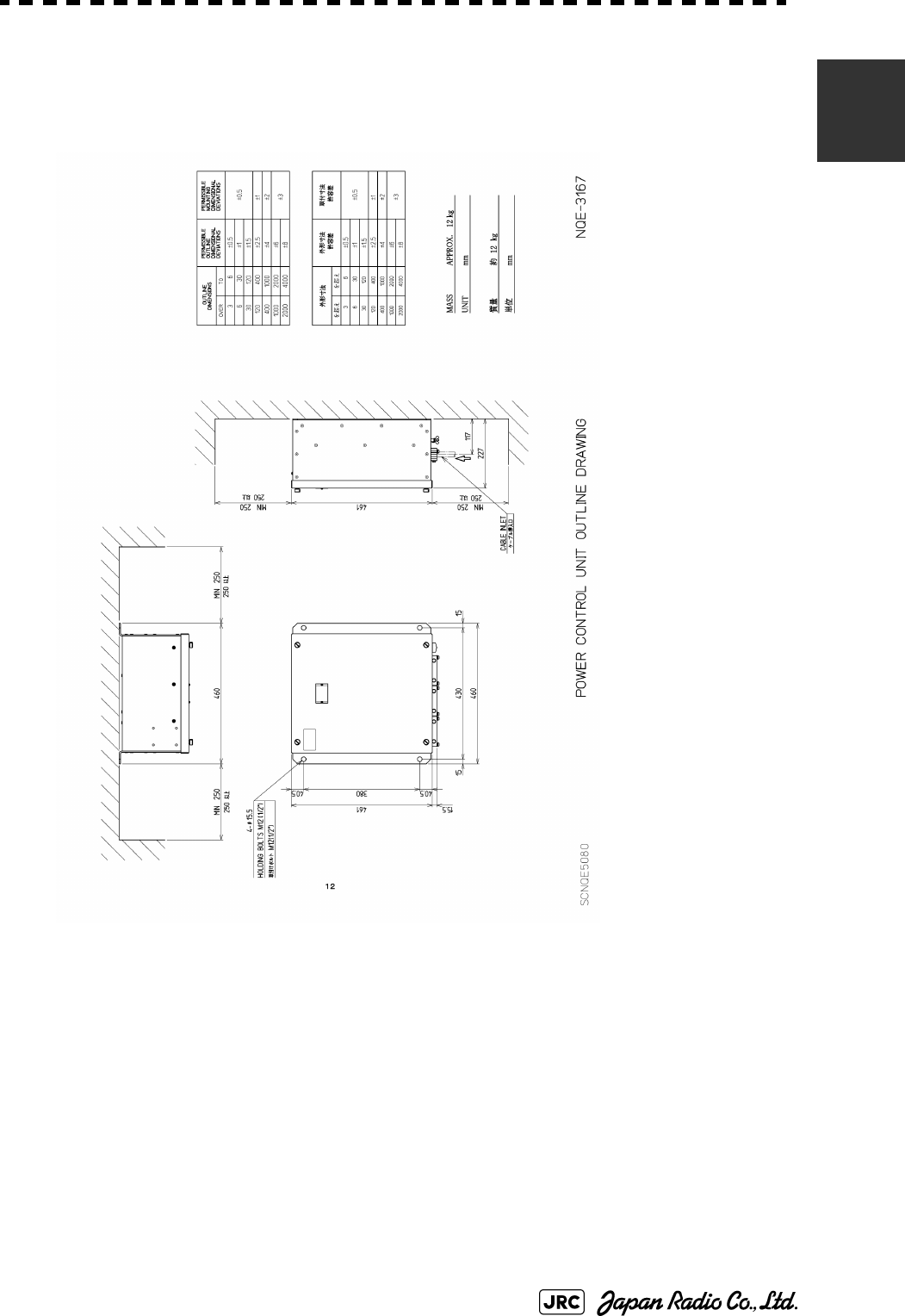
1.4 EXTERIOR DRAWINGS
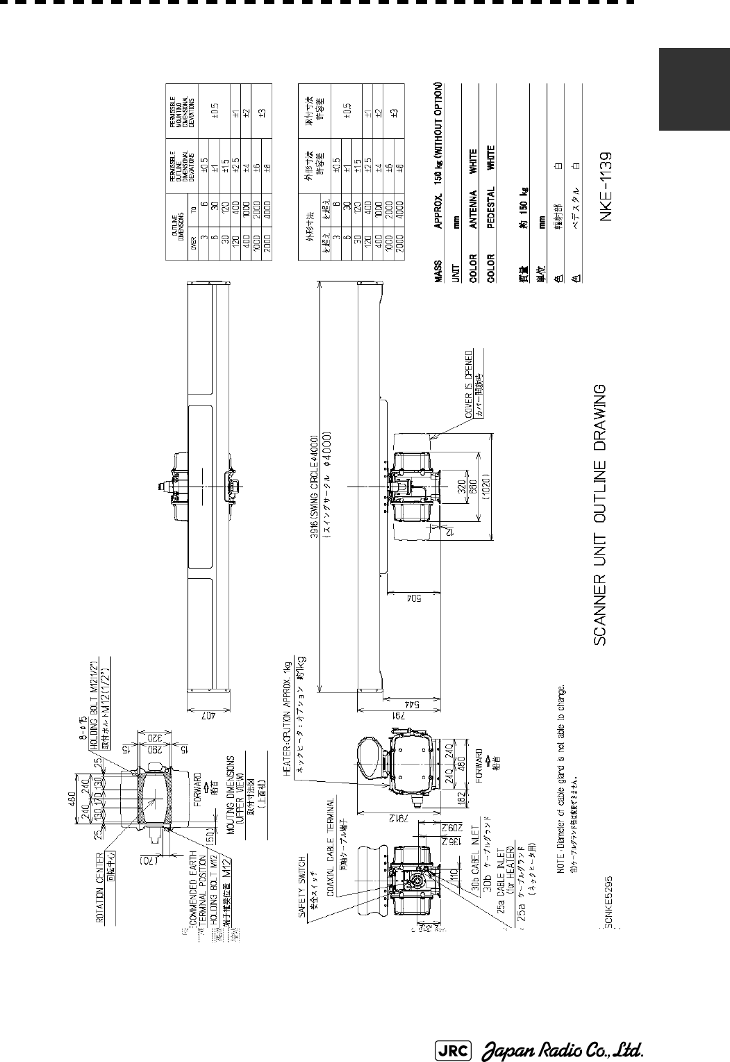
Fig 1-1: Outline Drawing of Scanner Unit, Type NKE-1139
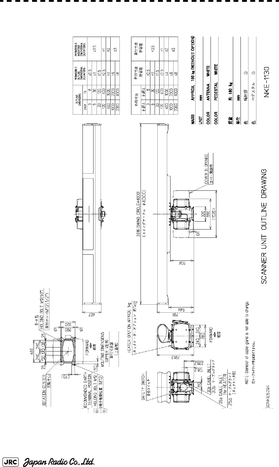
Fig 1-2: Outline Drawing of Scanner Unit, Type NKE-1130
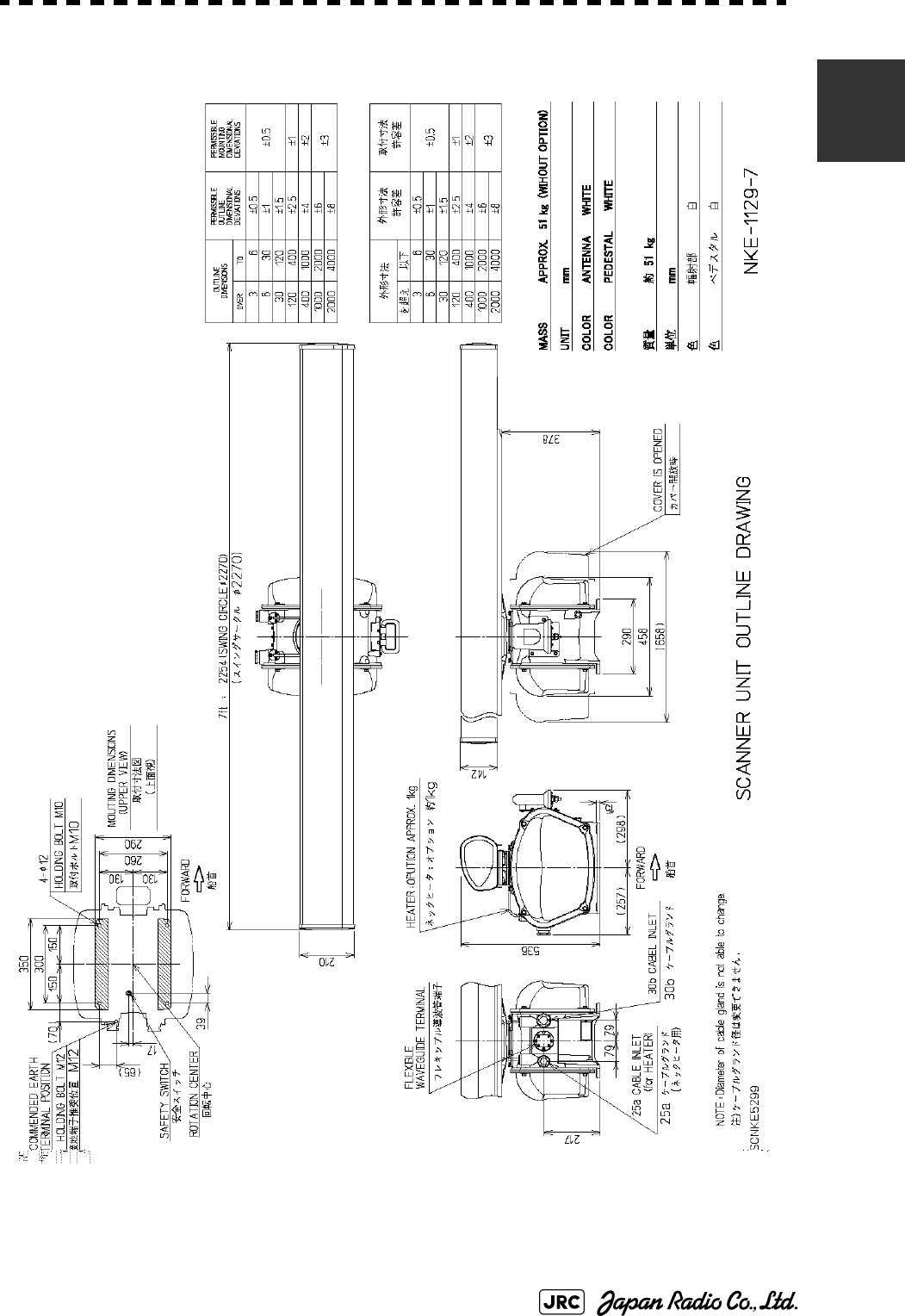
Fig 1-3: Outline Drawing of Scanner Unit, Type NKE-1129-7
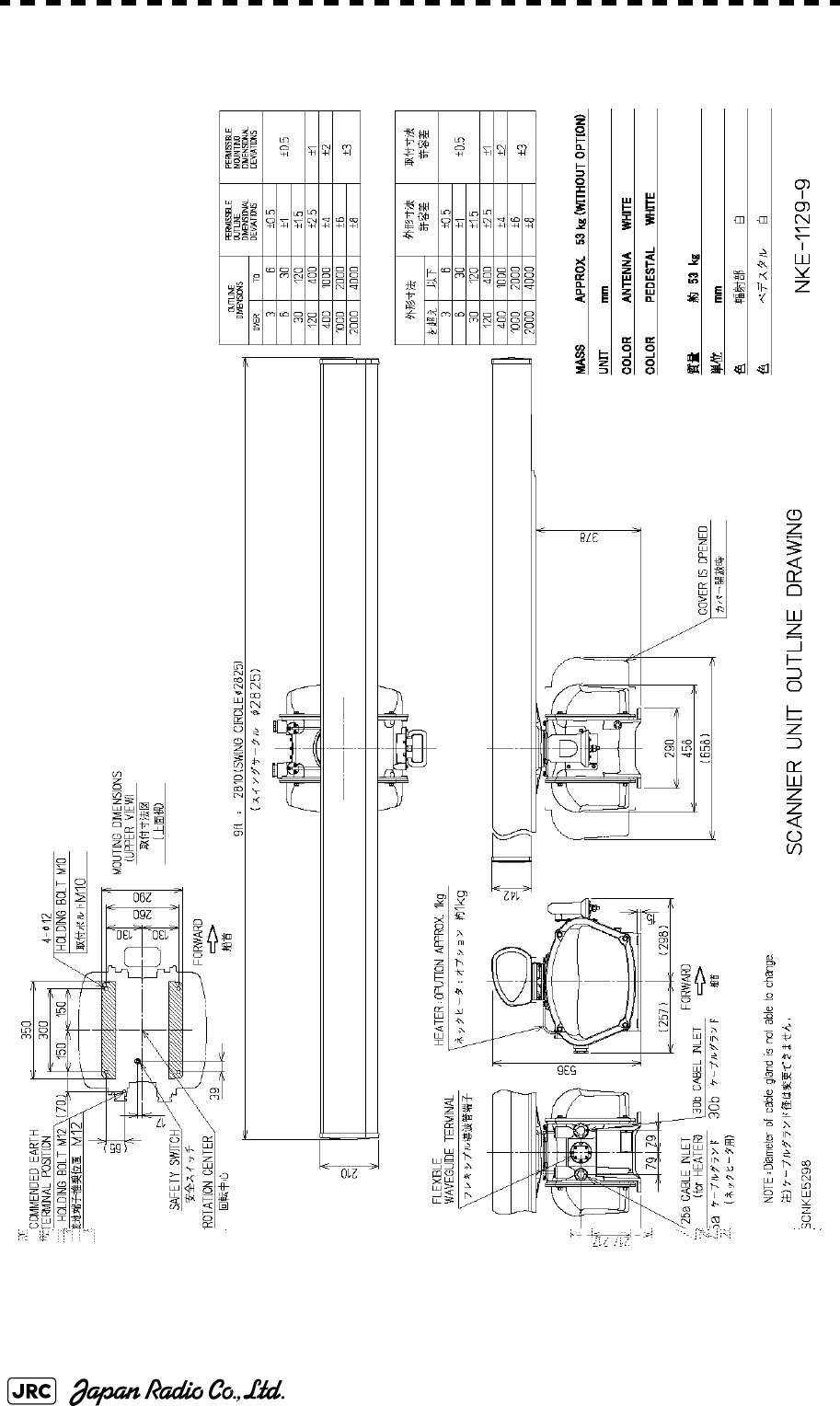
Fig 1-4: Outline Drawing of Scanner Unit, Type NKE-1129-9
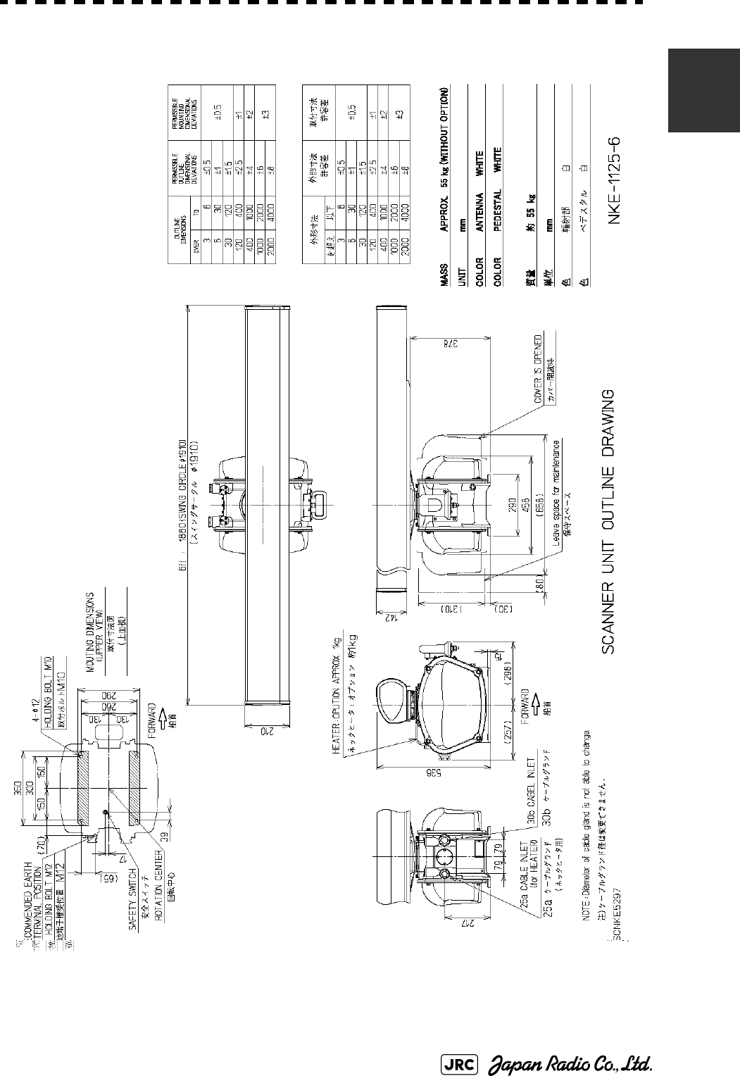
Fig 1-5: Outline Drawing of Scanner Unit, Type NKE-1125-6
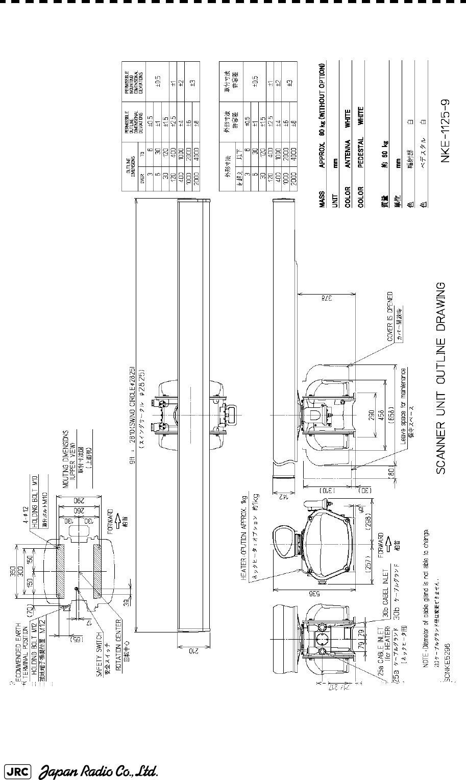
Fig 1-6: Outline Drawing of Scanner Unit, Type NKE-1125-9
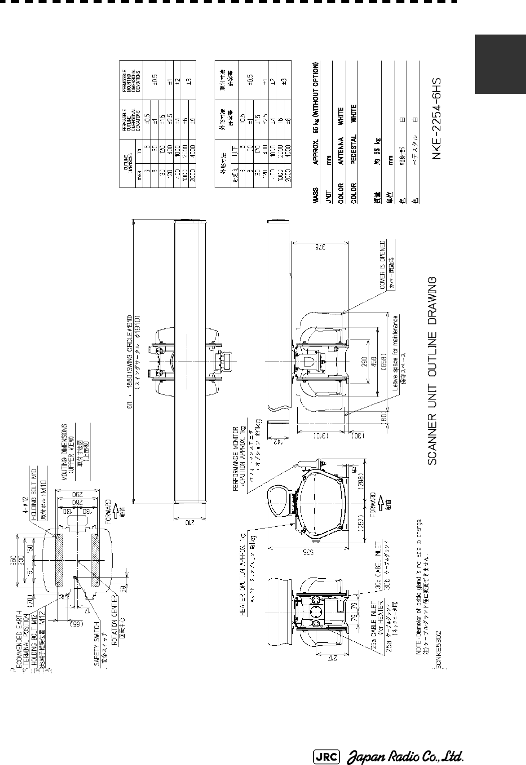
Fig 1-7: Outline Drawing of Scanner Unit, Type NKE-2254-6HS
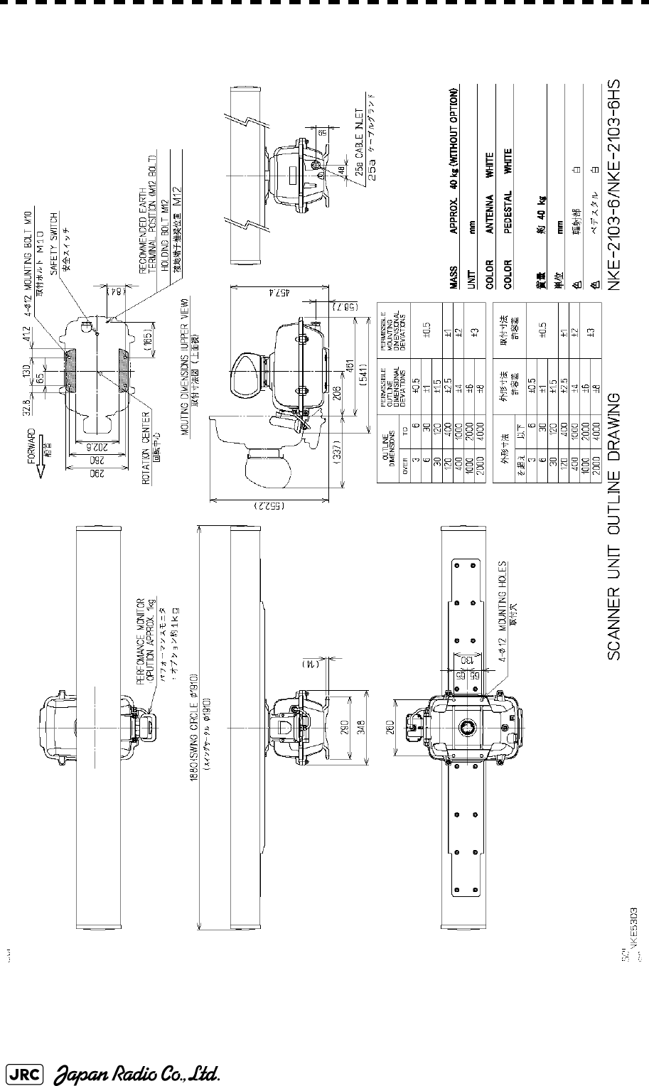
Fig 1-8: Outline Drawing of Scanner Unit, Type NKE-2103-6
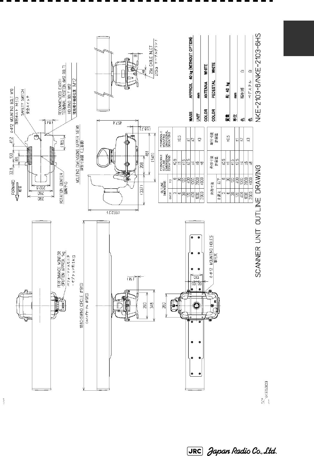
Fig 1-9: Outline Drawing of Scanner Unit, Type NKE-2103-6HS
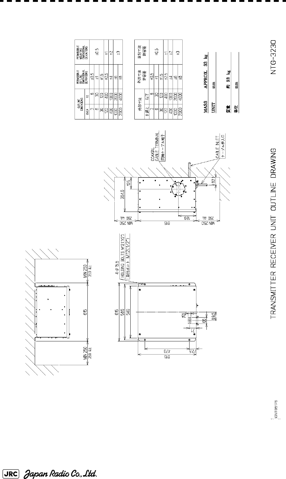
Fig 1-10: Outline Drawing of Transmitter Receiver Unit, Type NTG-3230
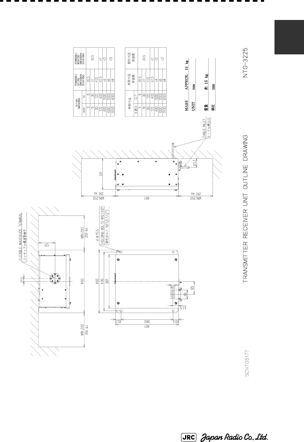
Fig 1-11: Outline Drawing of Transmitter Receiver Unit, Type NTG-3225
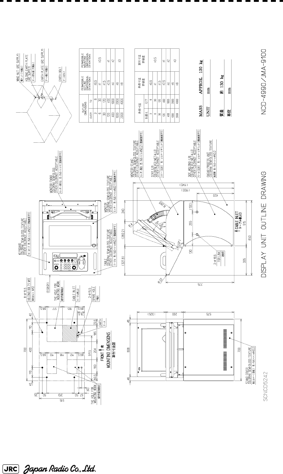
Fig 1-12: Outline Drawing of Display Unit, Type NCD-4990
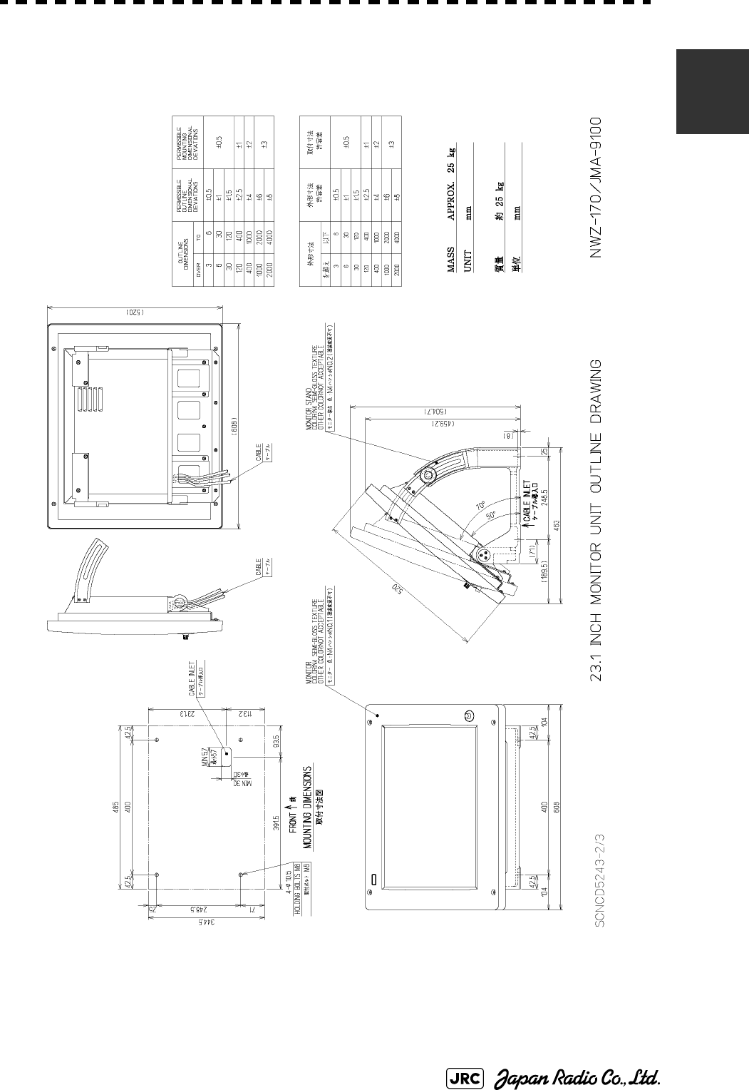
Fig 1-13: Outline Drawing of Monitor Unit, Type NWZ-170 (Desktop type option)
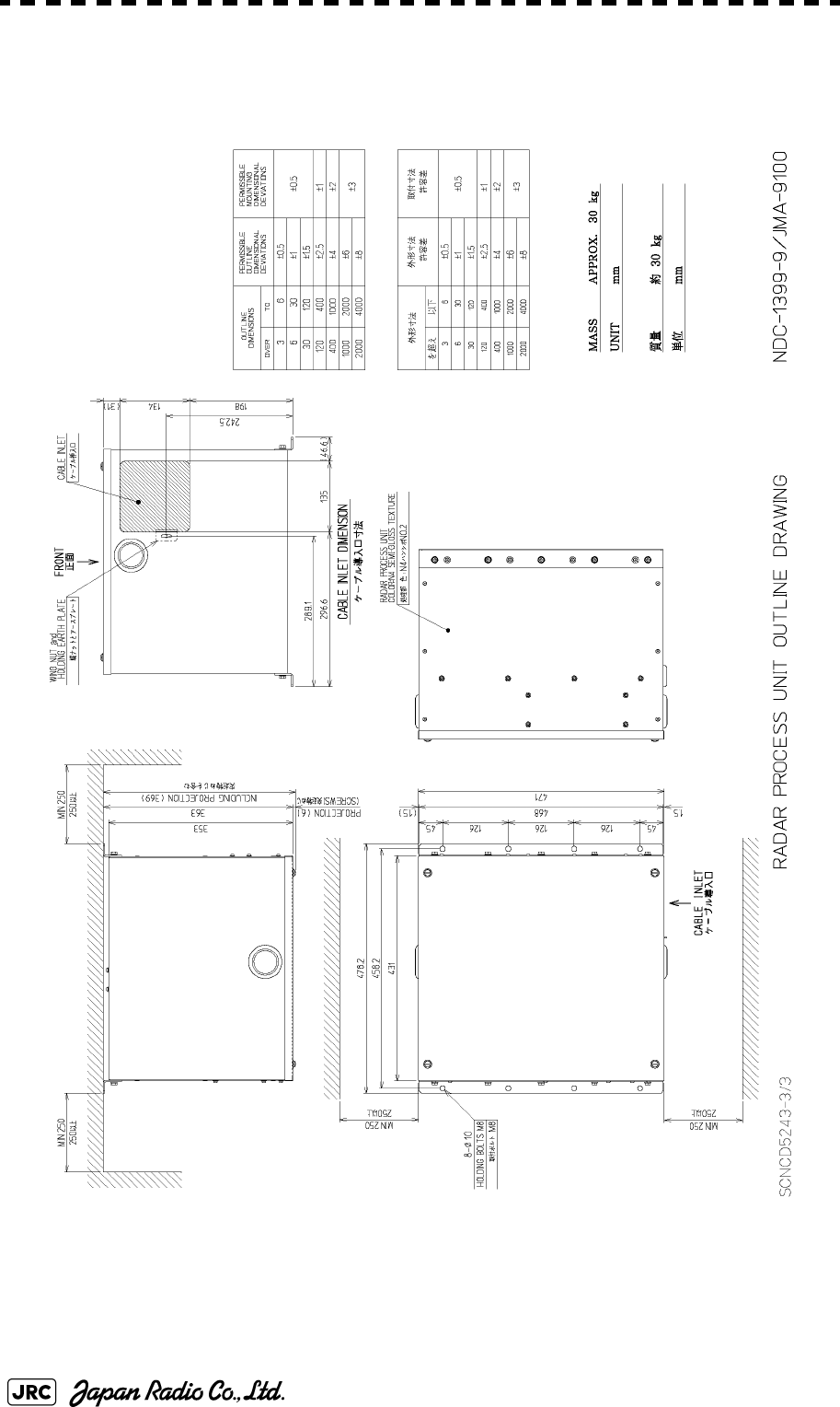
Fig 1-14: NDOutline Drawing of Radar Process Unit, Type NDC-1399-9 (Desktop type option)
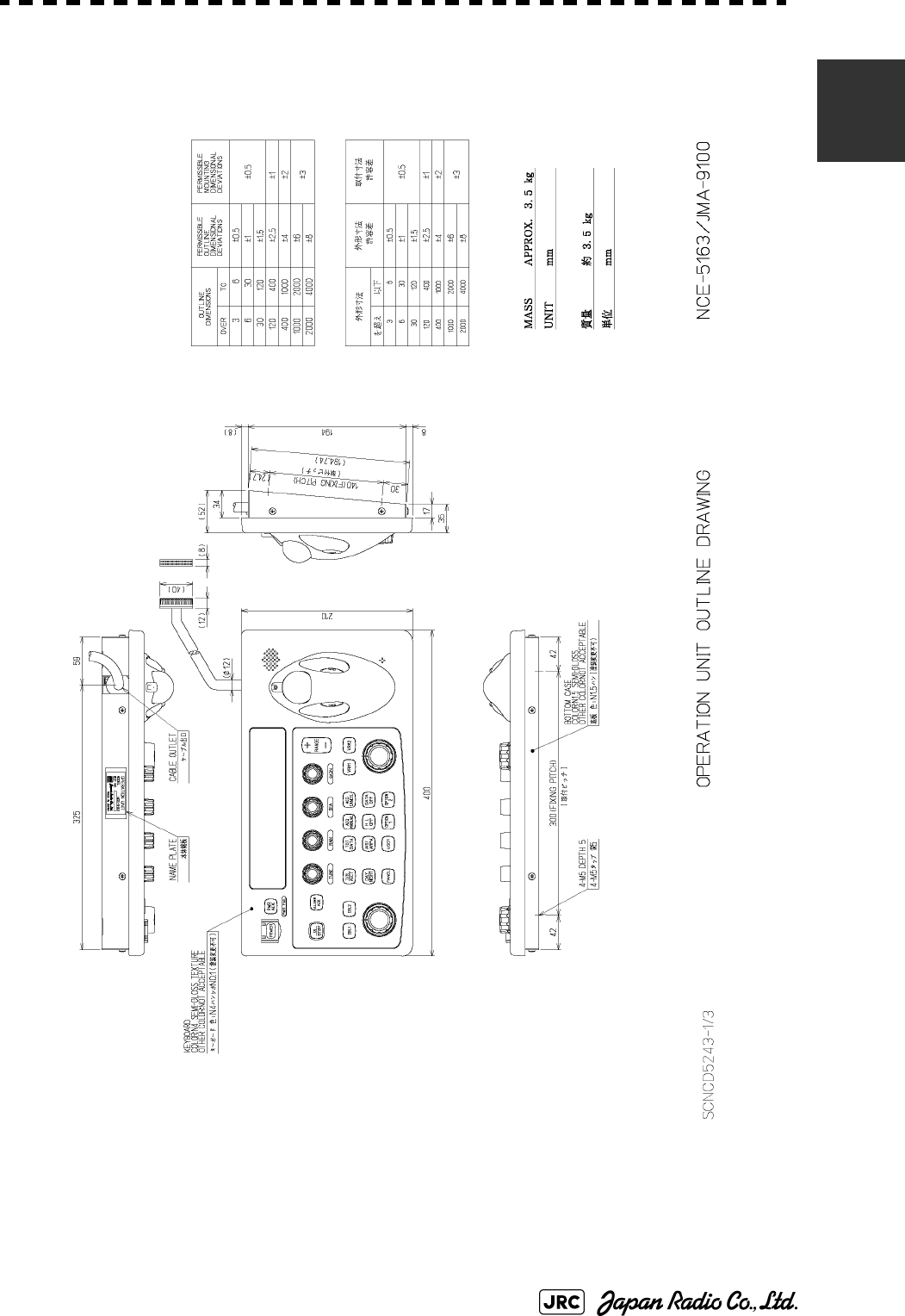
Fig 1-15: Outline Drawing of Operation Unit, Type NCE-5163 (Desktop type option)
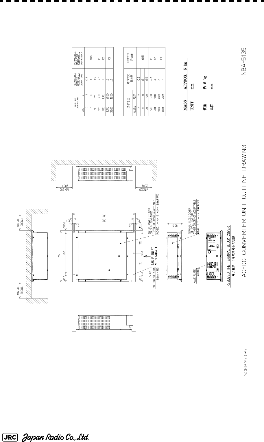
Fig 1-16: Outline Drawing of AC/DC Converter Unit, Type NBA-5135 (Desktop type option)
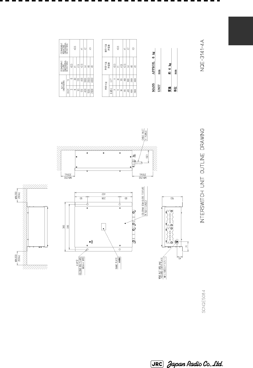
Fig 1-17: Outline Drawing of Interswitch Unit, Type NQE-3141-4A (Option)
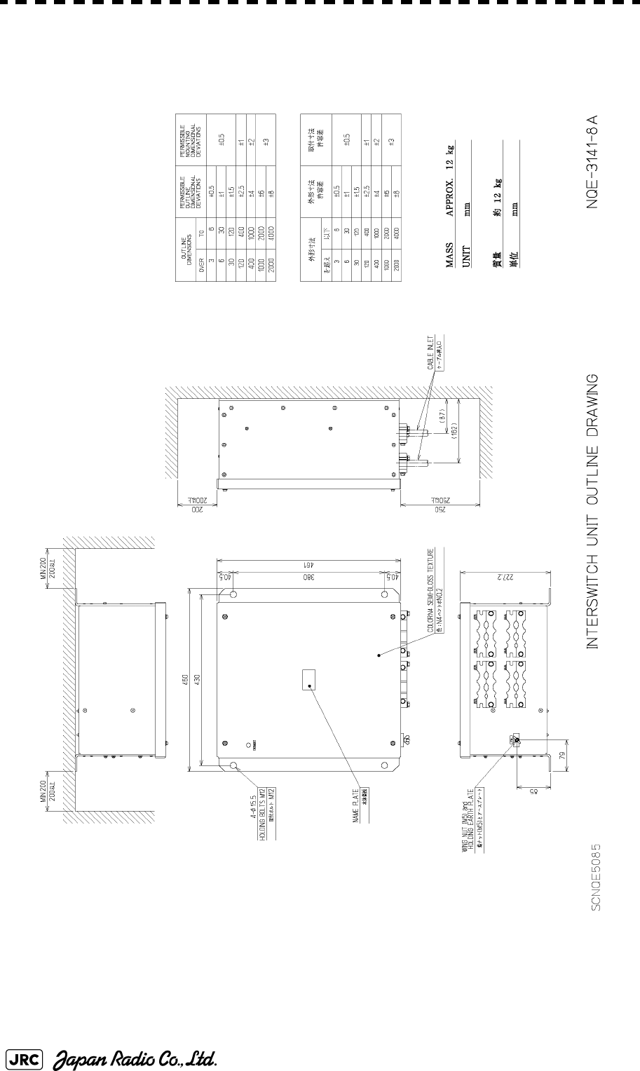
Fig 1-18: Outline Drawing of Interswitch Unit, Type NQE-3141-8A (Option)
Fig 1-19: Outline Drawing of Power Control Unit, Type NQE-3167 (Option)
JMA-9100 Instruction Manual > 1.GENERAL AND EQUIPMENT COMPOSITION > 1.4 EXTERIOR DRAWINGS
1-7
1
Fig 1-1: Outline Drawing of Scanner Unit, Type NKE-1139
1-8
JMA-9100 Instruction Manual > 1.GENERAL AND EQUIPMENT COMPOSITION > 1.4 EXTERIOR DRAWINGS
Fig 1-2: Outline Drawing of Scanner Unit, Type NKE-1130
JMA-9100 Instruction Manual > 1.GENERAL AND EQUIPMENT COMPOSITION > 1.4 EXTERIOR DRAWINGS
1-9
1
Fig 1-3: Outline Drawing of Scanner Unit, Type NKE-1129-7
1-10
JMA-9100 Instruction Manual > 1.GENERAL AND EQUIPMENT COMPOSITION > 1.4 EXTERIOR DRAWINGS
Fig 1-4: Outline Drawing of Scanner Unit, Type NKE-1129-9
JMA-9100 Instruction Manual > 1.GENERAL AND EQUIPMENT COMPOSITION > 1.4 EXTERIOR DRAWINGS
1-11
1
Fig 1-5: Outline Drawing of Scanner Unit, Type NKE-1125-6
1-12
JMA-9100 Instruction Manual > 1.GENERAL AND EQUIPMENT COMPOSITION > 1.4 EXTERIOR DRAWINGS
Fig 1-6: Outline Drawing of Scanner Unit, Type NKE-1125-9
JMA-9100 Instruction Manual > 1.GENERAL AND EQUIPMENT COMPOSITION > 1.4 EXTERIOR DRAWINGS
1-13
1
Fig 1-7: Outline Drawing of Scanner Unit, Type NKE-2254-6HS
1-14
JMA-9100 Instruction Manual > 1.GENERAL AND EQUIPMENT COMPOSITION > 1.4 EXTERIOR DRAWINGS
Fig 1-8: Outline Drawing of Scanner Unit, Type NKE-2103-6
JMA-9100 Instruction Manual > 1.GENERAL AND EQUIPMENT COMPOSITION > 1.4 EXTERIOR DRAWINGS
1-15
1
Fig 1-9: Outline Drawing of Scanner Unit, Type NKE-2103-6HS
1-16
JMA-9100 Instruction Manual > 1.GENERAL AND EQUIPMENT COMPOSITION > 1.4 EXTERIOR DRAWINGS
Fig 1-10: Outline Drawing of Transmitter Receiver Unit, Type NTG-3230
JMA-9100 Instruction Manual > 1.GENERAL AND EQUIPMENT COMPOSITION > 1.4 EXTERIOR DRAWINGS
1-17
1
Fig 1-11: Outline Drawing of Transmitter Receiver Unit, Type NTG-3225
1-18
JMA-9100 Instruction Manual > 1.GENERAL AND EQUIPMENT COMPOSITION > 1.4 EXTERIOR DRAWINGS
Fig 1-12: Outline Drawing of Display Unit, Type NCD-4990
JMA-9100 Instruction Manual > 1.GENERAL AND EQUIPMENT COMPOSITION > 1.4 EXTERIOR DRAWINGS
1-19
1
Fig 1-13: Outline Drawing of Monitor Unit, Type NWZ-170 (Desktop type option)
1-20
JMA-9100 Instruction Manual > 1.GENERAL AND EQUIPMENT COMPOSITION > 1.4 EXTERIOR DRAWINGS
Fig 1-14: NDOutline Drawing of Radar Process Unit, Type NDC-1399-9 (Desktop type option)
JMA-9100 Instruction Manual > 1.GENERAL AND EQUIPMENT COMPOSITION > 1.4 EXTERIOR DRAWINGS
1-21
1
Fig 1-15: Outline Drawing of Operation Unit, Type NCE-5163 (Desktop type option)
1-22
JMA-9100 Instruction Manual > 1.GENERAL AND EQUIPMENT COMPOSITION > 1.4 EXTERIOR DRAWINGS
Fig 1-16: Outline Drawing of AC/DC Converter Unit, Type NBA-5135 (Desktop type option)
JMA-9100 Instruction Manual > 1.GENERAL AND EQUIPMENT COMPOSITION > 1.4 EXTERIOR DRAWINGS
1-23
1
Fig 1-17: Outline Drawing of Interswitch Unit, Type NQE-3141-4A (Option)
1-24
JMA-9100 Instruction Manual > 1.GENERAL AND EQUIPMENT COMPOSITION > 1.4 EXTERIOR DRAWINGS
Fig 1-18: Outline Drawing of Interswitch Unit, Type NQE-3141-8A (Option)
JMA-9100 Instruction Manual > 1.GENERAL AND EQUIPMENT COMPOSITION > 1.4 EXTERIOR DRAWINGS
1-25
1
Fig 1-19: Outline Drawing of Power Control Unit, Type NQE-3167 (Option)

1-26
JMA-9100 Instruction Manual > 1.GENERAL AND EQUIPMENT COMPOSITION > 1.5 GENERAL SYSTEM DIAGRAMS
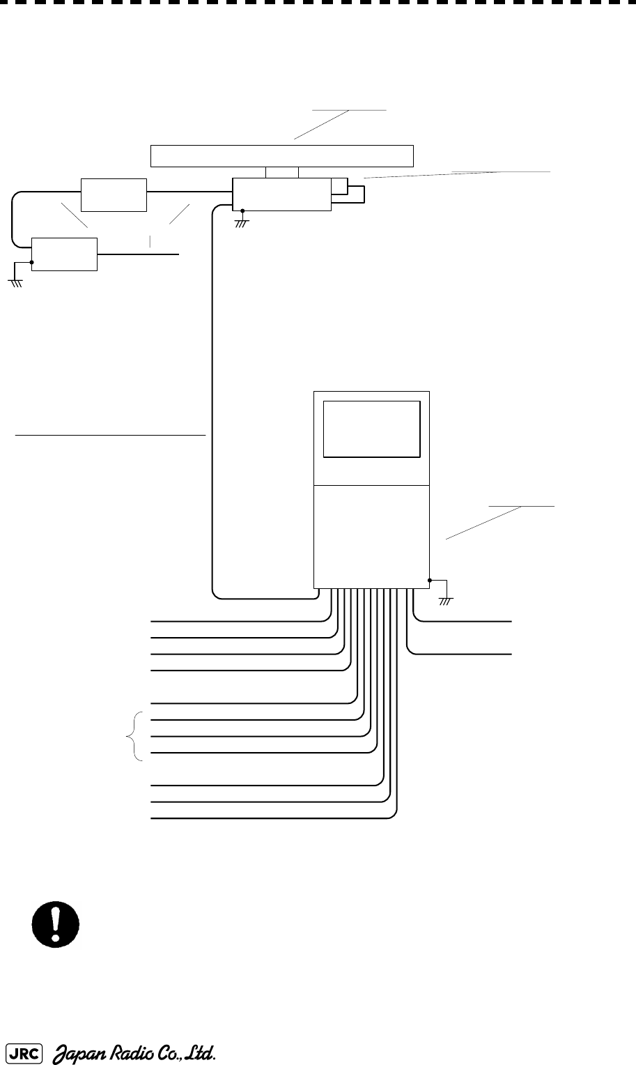
1.5 GENERAL SYSTEM DIAGRAMS
Fig 1-21: General System Diagram of Radar, Type JMA-9132-SA
Fig 1-22: General System Diagram of Radar, Type JMA-9123-7XA
Fig 1-23: General System Diagram of Radar, Type JMA-9123-9XA
Fig 1-24: General System Diagram of Radar, Type JMA-9122-6XA
Fig 1-25: General System Diagram of Radar, Type JMA-9122-9XA
Fig 1-26: General System Diagram of Radar, Type JMA-9122-6XAH
Fig 1-27: General System Diagram of Radar, Type JMA-9110-6XA
Fig 1-28: General System Diagram of Radar, Type JMA-9110-6XAH

JMA-9100 Instruction Manual > 1.GENERAL AND EQUIPMENT COMPOSITION > 1.5 GENERAL SYSTEM DIAGRAMS
1-27
1
Fig 1-20: General System Diagram of Radar, Type JMA-9133-SA
Eliminating the interference on frequencies used for marine communications and navigation
due to operation of the radar. All cables of the radar are to be run away from the cables of radio
equipment.(Ex. Radiotelephone. Communications receiver and direction finder, etc. )
Especially inter-wiring cables between scanner unit and display unit of the radar should not be
run parallel with the cables of radio equipment.
NCD-4990
DISPLAY UNIT
NJU-84
PERFORMANCE UNIT
250 V-MPYCYS -7
250 V-TTYCS-1
3C-2V x5 (MAX 30m)
250 V-TTYCS-1
18 CORES COMPOSITE CABLE
H-2695111153
MAX 18.0φ (JRC SUPPLY)
250 V-TTYCS-4
H-2695110006 (JRC SUPPLY )
H-2668510019 (JRC SUPPLY) SPARE
250V-MPYC-4
250 V-TTYCS-4
250 V-TTYCS-4
GYRO
LOG
(NMEA 0183)
DGPS
VDR
RADAR
(INTER SWITCH)
ECDIS
(JAN-901M)
ALERM MONITORING SYSTEM
(NEAREST APPROACH)
(PO WER FAI L)
CONNING DISPLAY
(JAN-701-CON)
AIS
0.6/1 kV-DPYCY-6
0 .6/1 k V-DPYCYS -1 .5
SHIP’S MAIN
AC220V,60Hz,1φ,800VA
SHIP’S MAIN
for POWER FAIL ALARM
DC24 V(B ATTER Y ),1W
(5A)
NBL-175
SHIP’S MAIN
for HEATER
AC220V,60Hz,1φ
AC100V,60Hz
1φ,200 W
CIRCUIT BREAKER
(SHIP YARD SUPPLY)
(WITH PM UNIT)
NKE-1139
SCANNER UNIT
14 CORES COMPOSITE CABLE
H-2695110056
MAX 23φ (JRC SUPPLY)
STEPDOWN
TRANSFORMER
NTG-3230
TRANSCEIVER UNIT
14 CORES COMPOSITE CABLE
H-2695110056
MAX 23φ (JRC SUPPLY)
COAXIAL CABLE
HF-20D (JRC SUPPLY)
0.6/1kV-DPYCYS-1.5
1-28
JMA-9100 Instruction Manual > 1.GENERAL AND EQUIPMENT COMPOSITION > 1.5 GENERAL SYSTEM DIAGRAMS
Fig 1-21: General System Diagram of Radar, Type JMA-9132-SA
Eliminating the interference on frequencies used for marine communications and navigation
due to operation of the radar. All cables of the radar are to be run away from the cables of radio
equipment.(Ex. Radiotelephone. Communications receiver and direction finder, etc. )
Especially inter-wiring cables between scanner unit and display unit of the radar should not be
run parallel with the cables of radio equipment.
NCD-4990
DISPLAY UNIT
NJU-84
PERFORMANCE UNIT
250 V-MPYCYS -7
250 V-TTYCS-1
3C-2V x5 (MAX 30m)
250 V-TTYCS-1
18 CORES COMPOSITE CABLE
H-2695111153
MAX 18.0φ (JRC SUPPLY)
250 V-TTYCS-4
H-2695110006 (JRC SUPPLY )
H-2668510019 (JRC SUPPLY) SPARE
250V-MPYC-4
250 V-TTYCS-4
250 V-TTYCS-4
GYRO
LOG
(NMEA 0183)
DGPS
VDR
RADAR
(INTER SWITCH)
ECDIS
(JAN-901M)
ALERM MONITORING SYSTEM
(NEAREST APPROACH)
(PO WER FAI L)
CONNING DISPLAY
(JAN-701-CON)
AIS
0.6/1 kV-DPYCY-6
0.6/1 kV-DPYCYS -1.5
SHIP’S MAIN
AC220V,60Hz,1φ,800VA
SHIP’S MAIN
for POWER FAIL ALARM
DC24V(BATTERY),1W
(5A)
NBL-175
SHIP’S MAIN
for HEATER
AC220V,60Hz,1φ
AC100V,60Hz
1φ,200 W
CIRCUIT BREAKER
(SHIP YARD SUPPLY)
(WITH PM UNIT)
NKE-1130
SCANNER UNIT
14 CORES COMPOSITE CABLE
H-2695110056
MAX 23φ (JRC SUPPLY)
STEPDOWN
TRANSFORMER
0.6/1kV-DPYCYS-1.5
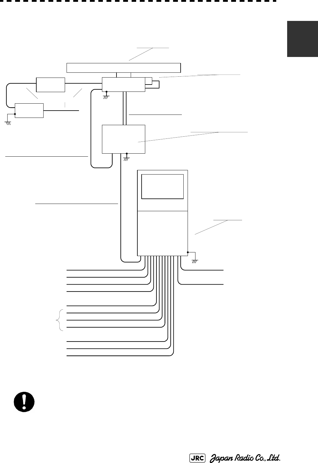
JMA-9100 Instruction Manual > 1.GENERAL AND EQUIPMENT COMPOSITION > 1.5 GENERAL SYSTEM DIAGRAMS
1-29
1
Fig 1-22: General System Diagram of Radar, Type JMA-9123-7XA
Eliminating the interference on frequencies used for marine communications and navigation
due to operation of the radar. All cables of the radar are to be run away from the cables of radio
equipment.(Ex. Radiotelephone. Communications receiver and direction finder, etc. )
Especially inter-wiring cables between scanner unit and display unit of the radar should not be
run parallel with the cables of radio equipment.
NCD-4990
DISPLAY UNIT
NJU-85
PERFORMANCE UNIT
250 V-MPYCYS -7
250 V-TTYCS-1
3C-2V x5 (MAX 30m)
250 V-TTYCS-1
18 CORES COMPOSITE CABLE
H-2695111153
MAX 18.0φ (JRC SUPPLY)
250 V-TTYCS-4
H-2695110006 (JRC SUPPLY )
H-2668510019 (JRC SUPPLY) SPARE
250V-MPYC-4
250 V-TTYCS-4
250 V-TTYCS-4
GYRO
LOG
(NMEA 0183)
DGPS
VDR
RADAR
(INTER SWITCH)
ECDIS
(JAN-901M)
ALERM MONITORING SYSTEM
(NEAREST APPROACH)
(PO WER FAI L)
CONNING DISPLAY
(JAN-701-CON)
AIS
0.6/1kV-DPYCY-6
0.6/1 kV-DPYCYS -1.5
SHIP’S MAIN
AC220V,60Hz,1φ,800 V A
SHIP’S MAIN
for POWER FAIL ALARM
DC24 V (B ATTER Y ),1W
(5A)
NBL-175
SHIP’S MAIN
for HEATER
AC220V,60Hz,1φ
AC100V,60Hz
1φ,200 W
CIRCUIT BREAKER
(SHIP YARD SUPPLY)
(WITH PM UNIT)
NKE-1129-7
SCANNER UNIT
14 CORES COMPOSITE CABLE
H-2695110056
MAX 23φ (JRC SUPPLY)
STEPDOWN
TRANSFORMER
NTG-3225
TRANSCEIVER UNIT
14 CORES COMPOSITE CABLE
H-2695110056
MAX 23φ (JRC SUPPLY)
FLEXIBLE WAVEGUIDE
FR-9 (JRC SUPPLY)
0.6/1kV-DPYCYS-1.5
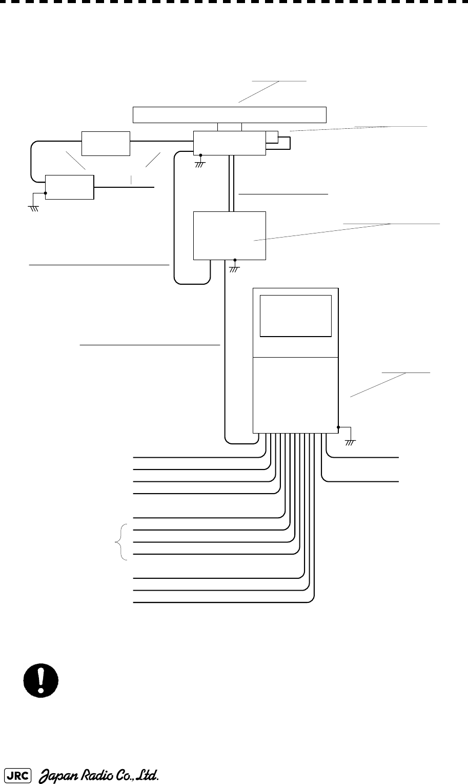
1-30
JMA-9100 Instruction Manual > 1.GENERAL AND EQUIPMENT COMPOSITION > 1.5 GENERAL SYSTEM DIAGRAMS
Fig 1-23: General System Diagram of Radar, Type JMA-9123-9XA
Eliminating the interference on frequencies used for marine communications and navigation
due to operation of the radar. All cables of the radar are to be run away from the cables of radio
equipment.(Ex. Radiotelephone. Communications receiver and direction finder, etc. )
Especially inter-wiring cables between scanner unit and display unit of the radar should not be
run parallel with the cables of radio equipment.
NCD-4990
DISPLAY UNIT
NJU-85
PERFORMANCE UNIT
250V-MPYCYS -7
250 V -TTYCS-1
3C-2V x5 (MAX 30 m)
250 V -TTYCS-1
18 CORES COMPOSITE CABLE
H-2695111153
MAX 18.0φ (JRC SUP P L Y)
250 V -TTYCS-4
H-2695110006 (JRC SUPPLY )
H-2668510019 (JRC SUPPLY) SPARE
250V-MPYC-4
250 V -TTYCS-4
250 V -TTYCS-4
GYRO
LOG
(NME A 0 1 83)
DGPS
VDR
RADAR
(INTER SWITCH)
ECDIS
(JAN-901M)
ALERM MONITORING SYSTEM
(NEAREST APPROACH)
(PO WER FAI L)
CONNING DISPLAY
(JAN-701-CON)
AIS
0.6/1 kV-DPYCY-6
0.6/1 kV-DPYCYS -1.5
(5A)
NBL-175
SHIP’S MAIN
for HEATER
AC220V,60Hz,1φ
AC100V,60Hz
1φ,200 W
CIRCUIT BREAKER
(SHIP YARD SUPPLY)
(WITH PM UNIT)
NKE-1129-9
SCANNER UNIT
14 CORES COMPOSITE CABLE
H-2695110056
MAX 23φ (JRC SUPPLY)
STEPDOWN
TRANSFORMER
NTG-3225
TRANSCEIVER UNIT
14 CORES COMPOSITE CABLE
H-2695110056
MAX 23φ (JRC S UP P LY)
FLEXIBLE WAVEGUIDE
FR-9 (JRC SUPPLY)
0.6/1kV-DPYCYS-1.5
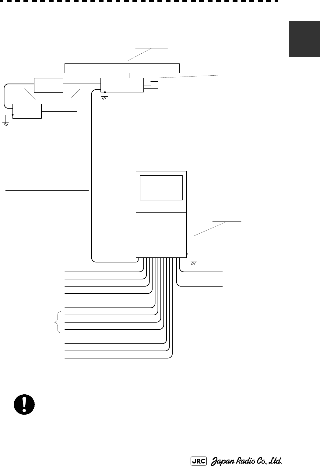
JMA-9100 Instruction Manual > 1.GENERAL AND EQUIPMENT COMPOSITION > 1.5 GENERAL SYSTEM DIAGRAMS
1-31
1
Fig 1-24: General System Diagram of Radar, Type JMA-9122-6XA
Eliminating the interference on frequencies used for marine communications and navigation
due to operation of the radar. All cables of the radar are to be run away from the cables of radio
equipment.(Ex. Radiotelephone. Communications receiver and direction finder, etc. )
Especially inter-wiring cables between scanner unit and display unit of the radar should not be
run parallel with the cables of radio equipment.
NCD-4990
DISPLAY UNIT
NJU-85
PERFORMANCE UNIT
250V-MPYCYS -7
250 V -TTYCS-1
3C-2V x5 (MAX 30 m)
250 V -TTYCS-1
18 CORES COMPOSITE CABLE
H-2695111153
MAX 18.0φ (JRC SUPPLY)
250 V -TTYCS-4
H-2695110006 (JRC SUPPLY )
H-2668510019 (JRC SUPPLY) SPARE
250V-MPYC-4
250 V -TTYCS-4
250 V -TTYCS-4
GYRO
LOG
(NMEA 0183)
DGPS
VDR
RADAR
(INTER SWITCH)
ECDIS
(JAN-901M)
ALERM MONITORING SYSTEM
(NEAREST APPROACH)
(POWER FAI L)
CONNING DISPLAY
(JAN-701-CON)
AIS
0.6/1kV-DPYCY-6
0.6/1kV-DPYCYS-1.5
SHIP’S MAIN
AC220 V,60Hz,1φ,800VA
SHIP’S MAIN
for POWER FAIL ALARM
DC24 V (B ATTER Y) ,1 W
(5A)
NBL-175
SHIP’S MAIN
for HEATER
AC220V,60Hz,1φ
AC100V,60Hz
1φ,200 W
CIRCUIT BREAKER
(SHIP YARD SUPPLY)
(WITH PM UNIT)
NKE-1125-6
SCANNER UNIT
14 CORES COMPOSITE CABLE
H-2695110056
MAX 23φ (JRC SUPPLY)
STEPDOWN
TRANSFORMER
0.6/1kV-DPYCYS-1.5
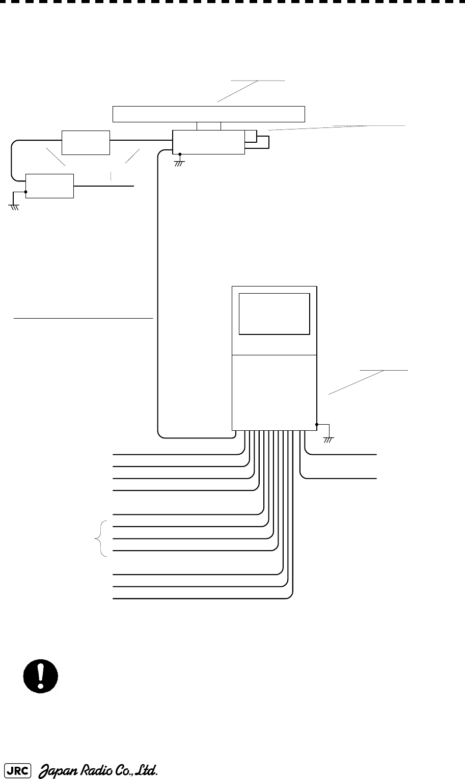
1-32
JMA-9100 Instruction Manual > 1.GENERAL AND EQUIPMENT COMPOSITION > 1.5 GENERAL SYSTEM DIAGRAMS
Fig 1-25: General System Diagram of Radar, Type JMA-9122-9XA
Eliminating the interference on frequencies used for marine communications and navigation
due to operation of the radar. All cables of the radar are to be run away from the cables of radio
equipment.(Ex. Radiotelephone. Communications receiver and direction finder, etc. )
Especially inter-wiring cables between scanner unit and display unit of the radar should not be
run parallel with the cables of radio equipment.
NCD-4990
DISPLAY UNIT
NJU-85
PERFORMANCE UNIT
250 V -MPYCYS -7
250V-TTYCS-1
3C-2V x5 (MAX 30m)
250V-TTYCS-1
18 CORES COMPOSITE CABLE
H-2695111153
MAX 18.0φ (JRC SUPPLY)
250V-TTYCS-4
H-2695110006 (JRC SUPPLY )
H-2668510019 (JRC SUPPLY) SPARE
250V-MPYC-4
250V-TTYCS-4
250V-TTYCS-4
GYRO
LOG
(NMEA 0183)
DGPS
VDR
RADAR
(INTER SWITCH)
ECDIS
(JAN-901M)
ALERM MONITORING SYSTEM
(NEAREST APPROACH)
(PO WER FAI L)
CONNING DISPLAY
(JAN-701-CON)
AIS
0.6/1 kV-DPYCY-6
0.6/1 kV-DPYCYS -1.5
SHIP’S MAIN
AC220 V ,60 Hz ,1 φ,800VA
SHIP’S MAIN
for POWER FAIL ALARM
DC24 V (B ATTER Y),1W
(5A)
NBL-175
SHIP’S MAIN
for HEATER
AC220 V ,60 Hz ,1φ
AC100V,60Hz
1φ,200 W
CIRCUIT BREAKER
(SHIP YARD SUPPLY)
(WITH PM UNIT)
NKE-1125-9
SCANNER UNIT
14 CORES COMPOSITE CABLE
H-2695110056
MAX 23φ (JRC SUPPLY)
STEPDOWN
TRANSFORMER
0.6/1kV-DPYCYS-1.5

JMA-9100 Instruction Manual > 1.GENERAL AND EQUIPMENT COMPOSITION > 1.5 GENERAL SYSTEM DIAGRAMS
1-33
1
Fig 1-26: General System Diagram of Radar, Type JMA-9122-6XAH
Eliminating the interference on frequencies used for marine communications and navigation
due to operation of the radar. All cables of the radar are to be run away from the cables of radio
equipment.(Ex. Radiotelephone. Communications receiver and direction finder, etc. )
Especially inter-wiring cables between scanner unit and display unit of the radar should not be
run parallel with the cables of radio equipment.
NCD-4990
DISPLAY UNIT
NJU-85
PERFORMANCE UNIT
250V-MPYCYS -7
250 V -TTYCS-1
3C-2V x5 (MAX 30 m)
250 V -TTYCS-1
18 CORES COMPOSITE CABLE
H-2695111153
MAX 18.0φ (JRC SUPPLY)
250 V -TTYCS-4
H-2695110006 (JRC SUPPLY )
H-2668510019 (JRC SUPPLY) SPARE
250V-MPYC-4
250 V -TTYCS-4
250 V -TTYCS-4
GYRO
LOG
(NMEA 0183)
DGPS
VDR
RADAR
(INTER SWITCH)
ECDIS
(JAN-901M)
ALERM MONITORING SYSTEM
(NEAREST APPROACH)
(POWER FAI L)
CONNING DISPLAY
(JAN-701-CON)
AIS
0.6/1kV-DPYCY-6
0.6/1kV-DPYCYS-1.5
SHIP’S MAIN
AC220 V,60Hz,1φ,800VA
SHIP’S MAIN
for POWER FAIL ALARM
DC24 V (B ATTER Y) ,1 W
(5A)
NBL-175
SHIP’S MAIN
for HEATER
AC220V,60Hz,1φ
AC100V,60Hz
1φ,200 W
CIRCUIT BREAKER
(SHIP YARD SUPPLY)
(WITH PM UNIT)
NKE-2254-6HS
SCANNER UNIT
14 CORES COMPOSITE CABLE
H-2695110056
MAX 23φ (JRC SUPPLY)
STEPDOWN
TRANSFORMER
0.6/1kV-DPYCYS-1.5
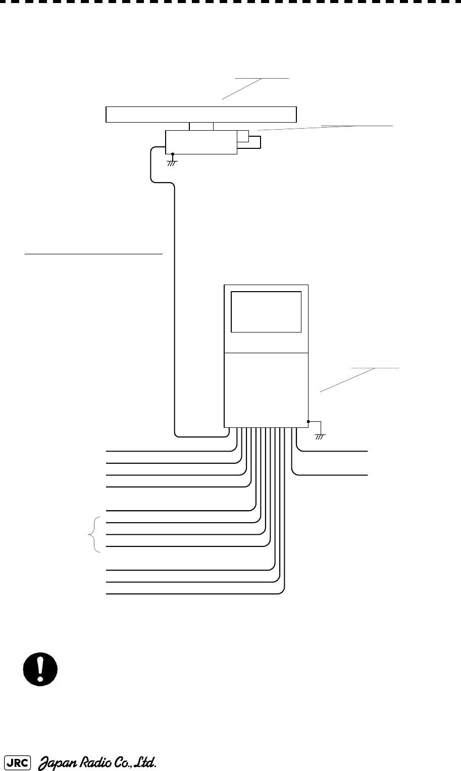
1-34
JMA-9100 Instruction Manual > 1.GENERAL AND EQUIPMENT COMPOSITION > 1.5 GENERAL SYSTEM DIAGRAMS
Fig 1-27: General System Diagram of Radar, Type JMA-9110-6XA
Eliminating the interference on frequencies used for marine communications and navigation
due to operation of the radar. All cables of the radar are to be run away from the cables of radio
equipment.(Ex. Radiotelephone. Communications receiver and direction finder, etc. )
Especially inter-wiring cables between scanner unit and display unit of the radar should not be
run parallel with the cables of radio equipment.
NCD-4990
DISPLAY UNIT
250 V-MPYCYS -7
250V-TTYCS-1
3C-2V x5 (MAX 30m )
250V-TTYCS-1
18 CORES COMPOSITE CABLE
H-2695111153
MAX 18.0φ (JRC SUPPLY)
250V-TTYCS-4
H-2695110006 (JRC SUPPLY )
H-2668510019 (JRC SUPPLY) SPARE
250 V-MPYC - 4
250V-TTYCS-4
250V-TTYCS-4
GYRO
LOG
(NMEA 0183)
DGPS
VDR
RADAR
(I NTE R SWI TCH)
ECDIS
(JAN-901M)
ALERM MONITORING SYSTEM
(NEAREST APPROACH)
(POWER FAIL)
CONNING DISPLAY
(JAN- 701-CON)
AIS
0.6/1kV-DPYCY -6
0. 6/1k V-DPYCYS - 1. 5
SHIP’S MAIN
AC220 V, 60Hz ,1 φ,800VA
SHIP’S MAIN
for POWER FAIL ALARM
DC24V(BATTERY),1W
NKE-2103-6
SCANNER UNIT
19 CORES COMPOSITE CABLE
CFQ-6912-**
MAX 14.5φ (JRC SUPPLY)
NJU-85
PERFORMANCE UNIT
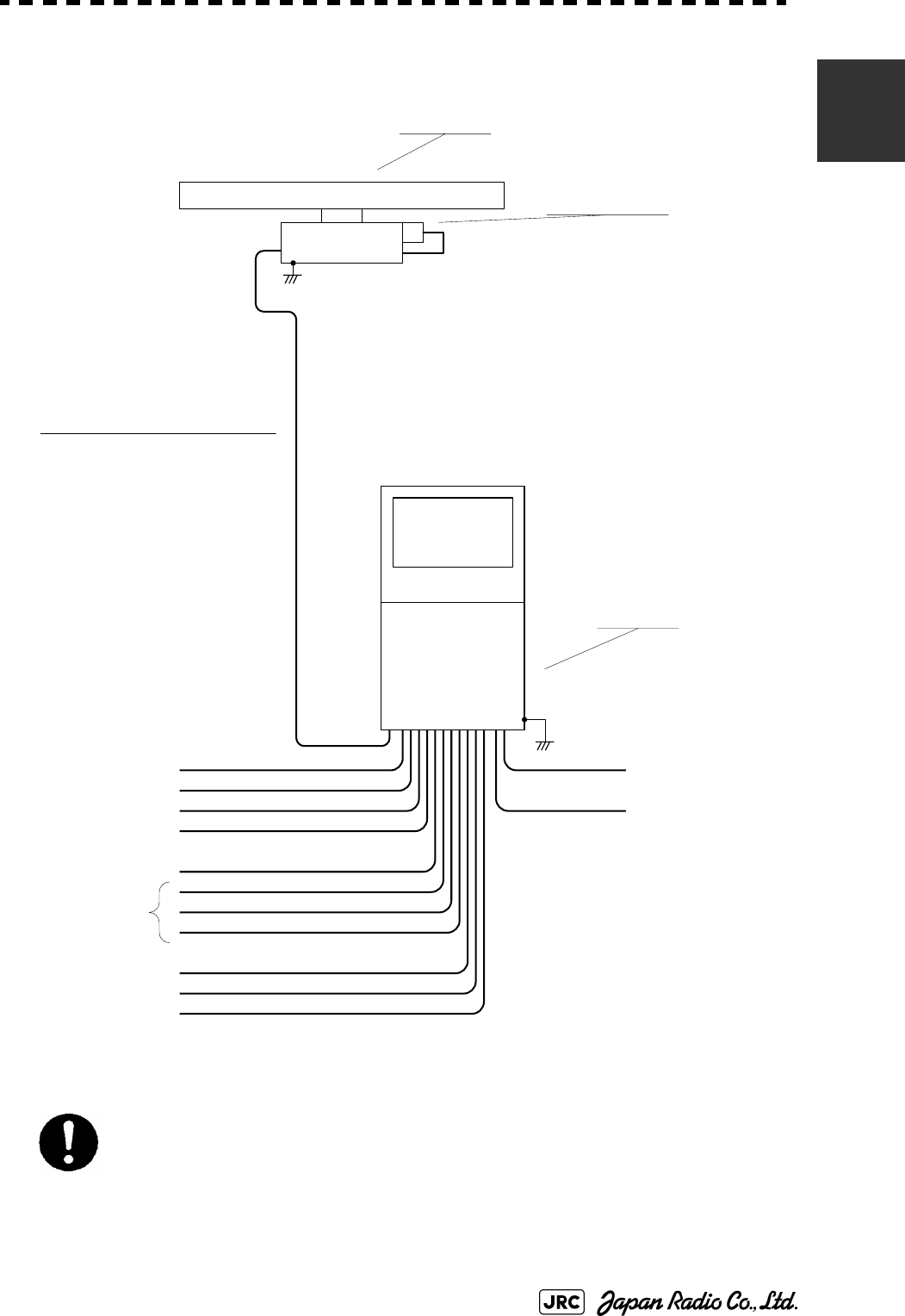
JMA-9100 Instruction Manual > 1.GENERAL AND EQUIPMENT COMPOSITION > 1.5 GENERAL SYSTEM DIAGRAMS
1-35
1
Fig 1-28: General System Diagram of Radar, Type JMA-9110-6XAH
Eliminating the interference on frequencies used for marine communications and navigation
due to operation of the radar. All cables of the radar are to be run away from the cables of radio
equipment.(Ex. Radiotelephone. Communications receiver and direction finder, etc. )
Especially inter-wiring cables between scanner unit and display unit of the radar should not be
run parallel with the cables of radio equipment.
NCD-4990
DISPLAY UNIT
250 V-MPYCYS -7
250V-TTYCS-1
3C-2V x 5 (MAX 30m)
250V-TTYCS-1
18 CORES COMPOSITE CABLE
H-2695111153
MAX 18.0φ (JRC SUPPLY)
250V-TTYCS-4
H-2695110006 (JRC SUPPLY )
H-2668510019 (JRC SUPPLY) SPARE
250 V-MPYC - 4
250V-TTYCS-4
250V-TTYCS-4
GYRO
LOG(NMEA 0183)
DGPS
VDR
RADAR(I NT E R SWI TCH)
ECDIS(JAN-901M)
ALERM MONITORING SYSTEM
(NE ARE ST APPROACH)
(POWER FAIL)
AIS
0.6/1kV-DPYCY -6
0. 6/1k V-DPYCYS - 1. 5
SHIP’S MAIN
AC220V,60Hz,1φ,800 VA
SHIP’S MAIN
for POWER FAIL ALARM
DC 24 V(B ATTER Y), 1W
NKE-2103-6HS
SCANNER UNIT
19 CORES COMPOSITE CABLE
CFQ-6912-**
MAX 14.5φ (JRC SUPPLY)
NJU-85
PERFORMANCE UNIT

1-36
JMA-9100 Instruction Manual > 1.GENERAL AND EQUIPMENT COMPOSITION > 1.5 GENERAL SYSTEM DIAGRAMS

NAMES AND FUNCTIONS OF CONTROL PANEL KEYS AND FUNCTIONS OF SOFTWARE BUTTONS
2.1 NAMES OF DISPLAY .............................................................................2-1
2.2 NAMES AND FUNCTIONS OF CONTROL PANEL KEYS ..................2-11
2.3 FUNCTIONS OF SOFTWARE BUTTONS ...........................................2-16
SECTION 2
NAMES AND FUNCTIONS OF CONTROL
PANEL KEYS AND FUNCTIONS OF
SOFTWARE BUTTONS
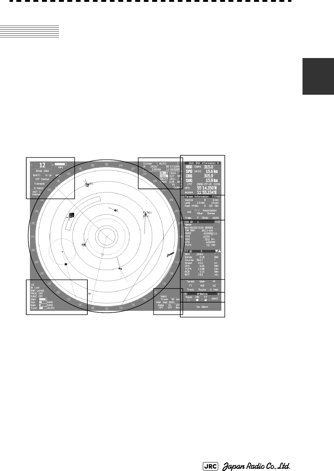
JMA-9100 Instruction Manual > 2.CONTROL PANEL KEYS and SOFTWARE BUTTONS> 2.1 NAMES OF DISPLAY
2-1
2
2.1 NAMES OF DISPLAY
Example of screen display
In this example, the screen is divided into a number of areas and the names in
each area are indicated.
PPI
Upper left
of the display
Lower left
of the display
Upper right
of the display
Lower right
of the display
Own ship's
information
Digital information
Target
tracking (TT) /
AIS information
Menu
Brilliance /
Display information
Alarm
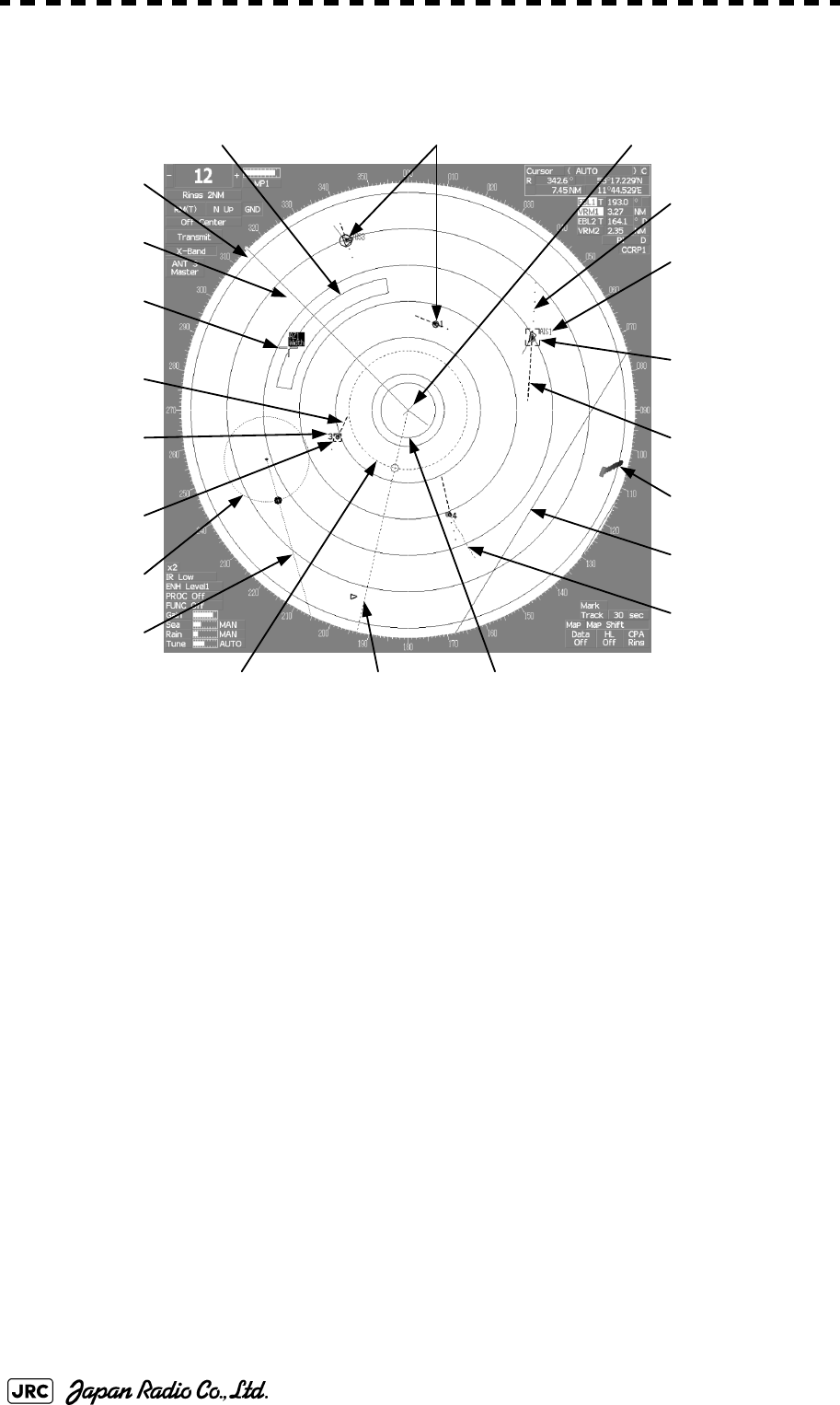
2-2
JMA-9100 Instruction Manual > 2.CONTROL PANEL KEYS and SOFTWARE BUTTONS > 2.1 NAMES OF DISPLAY
PPI
Tracked target
vector
Own ship's symbol
Automatic acquisition /
activation zone
Cursor mark
EBL2
Tracked target
symbol
AIS target vector
AIS target symbol
EBL1VRM1
VRM2
Ship's
heading line
Other ship's track
Past position
Association target
Tracked target
number
AIS target number
Ship's heading
marker
Parallel index lines
Radar trails
CPA ring
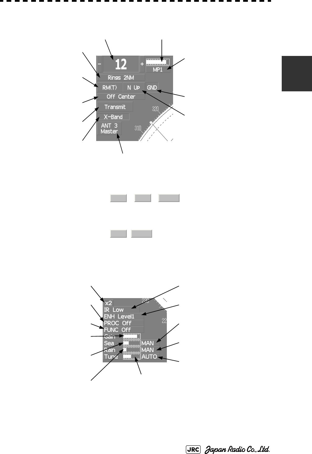
JMA-9100 Instruction Manual > 2.CONTROL PANEL KEYS and SOFTWARE BUTTONS> 2.1 NAMES OF DISPLAY
2-3
2
Upper left of the display
About ground and sea stabilization
Lower left of the display
Speed sensor source is , ,
If Set/Drift Setting menu is on :GND (Ground stabilization)
If Set/Drift Setting menu is off :Sea (Sea stabilization)
Speed sensor source is ,:GND (Ground stabilization)
Range scale
Range rings display On / Off
Range rings interval
Motion mode true / relative
Radar trail true / relative
Off center
On / Off
Transmission / standby
X / S band
Interswitch connection status
Tuning indication
Transmission pulse length
Stability mode
Azimuth display mode
MAN LOG
2AXW
GPS
2AXG
Target enhance (ENH) mode
Radar video processing (PROC)
mode
Function (FUNC) mode
Double zoom On / Off
Interference rejection (IR) mode
Sea clutter uppression (Sea)
dial position
Rain / snow clutter
suppression (Rain)
dial position
Tune dial position
Sea clutter suppression (Sea)
mode
Rain / snow clutter suppression
(Rain) mode
Gain dial position
Tune mode
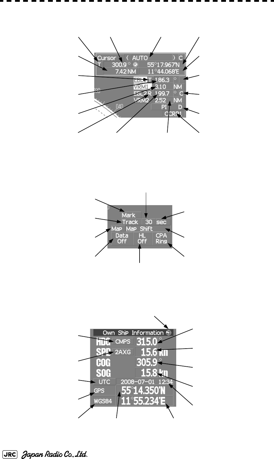
2-4
JMA-9100 Instruction Manual > 2.CONTROL PANEL KEYS and SOFTWARE BUTTONS > 2.1 NAMES OF DISPLAY
Upper right of the display
Lower right of the display
Own ship's information
Cursor bearing
numeric value indication
true / relative
EBL1 bearing
VRM1 range
EBL1
starting point mode
EBL2
starting point mode
Parallel index line
starting point mode
EBL2 numeric value indication
true / relative VRM2 rangeEBL2 bearing
EBL1 numeric value indication
true / relative
Cursor longitude
Cursor latitude
Cursor mode
Cursor range
Cursor bearing
Consistent Common
Reference Point (CCRP)
Own ship's track color
Own ship's track interval
Map display
On / Off
Own ship's track interval unit
Map position correction
indication
CPA ring display
On / Off
Mark color
Graphic display
On / Off
Ship's heading line
On / Off
Own ship's latitude
Heading device
Speed sensor
Time display mode
Own ship's speed
Ship's heading bearing
Own ship's
speed over ground
Own ship's
course over ground
Own ship's longitude
Date and time
Operation status
Positioning system
(example: GPS, DGPS )
Geodetic positioning system
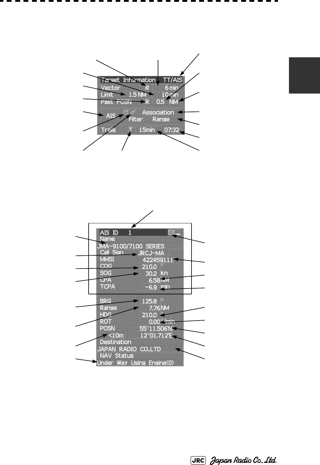
JMA-9100 Instruction Manual > 2.CONTROL PANEL KEYS and SOFTWARE BUTTONS> 2.1 NAMES OF DISPLAY
2-5
2
Target tracking (TT) / AIS information
Numeric information: AIS target information
Past position display
interval
Target tracking (TT) /
EPA / AIS
Association On / Off
Radar trails display time
Radar trails remaining time
Radar trails true / relative
Target vector true / relative Target vector length
Past position true / relative
Past position display
interval unit
CPA limit
TCPA limit
AIS On / Off
AIS target symbol display
On / Off
Tracked target symbol
display On / Off
AIS filter mode
Ship's name
Call sign
MMSI
Course
Speed
CPA
TCPA
Bearing
Range
Ship's heading bearing
Rate of turn
Latitude
Longitude
DestinationNavigation status
Latitude / longitude error
Simple display item
AIS target number
Unread message
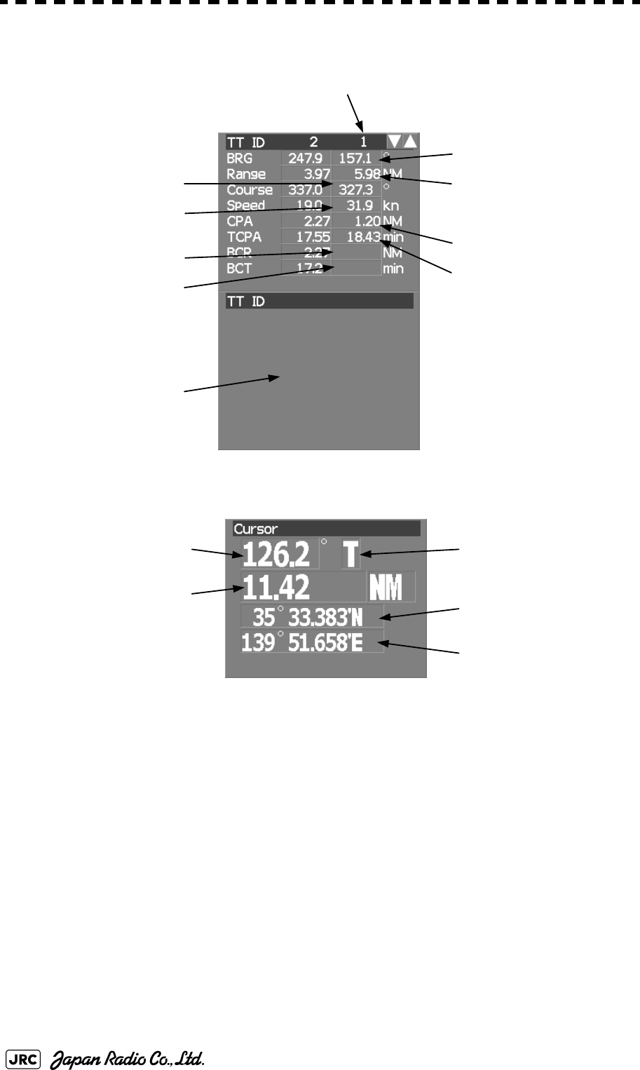
2-6
JMA-9100 Instruction Manual > 2.CONTROL PANEL KEYS and SOFTWARE BUTTONS > 2.1 NAMES OF DISPLAY
Numeric information: Tracked target information
Numeric information: Enhancement of cursor position numeric value indication
Bearing
RangeTrue course
True speed
CPA
TCPA
BCR
BCT
Tracked target number
No information is displayed
if digital information value is
not displayed
Cursor longitude
Cursor latitude
Cursor bearing numeric
value indication
true / relative
Cursor bearing
Cursor range
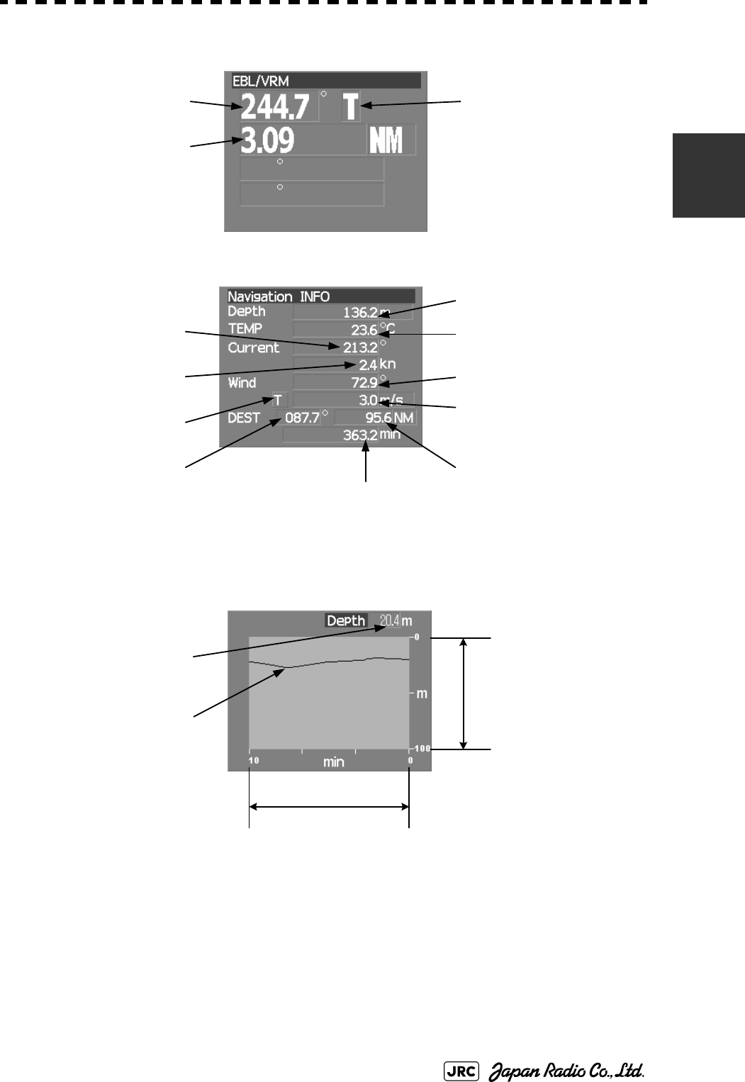
JMA-9100 Instruction Manual > 2.CONTROL PANEL KEYS and SOFTWARE BUTTONS> 2.1 NAMES OF DISPLAY
2-7
2
Numeric information: Enhancement of EBL / VRM numeric value display
Numeric information: Navigation information
Graph information: Depth indication
VRM range
EBL bearing
EBL bearing
numeric value indication
true / relative
Wind direction / speed
numeric value indication
true / relative
Depth
Water temperatureCurrent direction
Current speed
Destination bearing
Remaining time before
arriving destination
Destination distance
Wind direction
Wind speed
Depth
Depth graph
Depth range
Time range
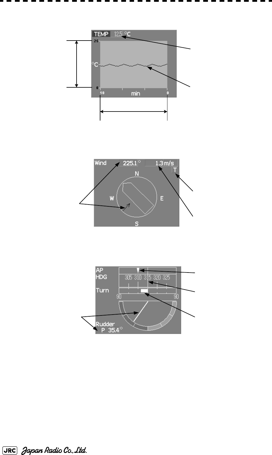
2-8
JMA-9100 Instruction Manual > 2.CONTROL PANEL KEYS and SOFTWARE BUTTONS > 2.1 NAMES OF DISPLAY
Graph information: Water temperature indication
Graph information: Wind direction / speed
Graph information: Course bar
Water temperature
Water temperature graph
Water temperature range
Time range
Wind speed
Wind direction / speed
true / relative
Wind direction
Ship's heading bearing
Auto pilot course
Rudder Rate of turn
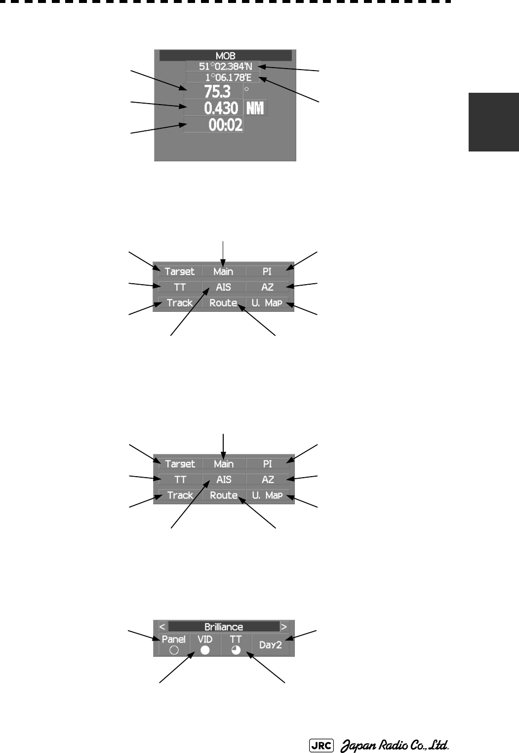
JMA-9100 Instruction Manual > 2.CONTROL PANEL KEYS and SOFTWARE BUTTONS> 2.1 NAMES OF DISPLAY
2-9
2
Numeric information: Marker
Menu
Brilliance
Display information
Marker longitude
Marker latitude
Marker range
Marker bearing
Arrival time
Digital information
Target Tracking (TT) menu
User map menu
Parallel index line menu
Own Track menu
Route menu
Main menu
AIS menu
Automatic acquisition /
activation zone (AZ) menu
Digital information
Target Tracking (TT) menu
User map menu
Parallel index line menu
Own Track menu
Route menu
Main menu
AIS menu
Automatic acquisition /
activation zone (AZ) menu
Panel lighting brilliance
Radar video brilliance
Day / night mode
Tracked target / AIS target
symbol brilliance

2-10
JMA-9100 Instruction Manual > 2.CONTROL PANEL KEYS and SOFTWARE BUTTONS > 2.1 NAMES OF DISPLAY
Alarm
Alarm indication
(The system alarm indicated in red.
Other information indicated in blue or yellow.)
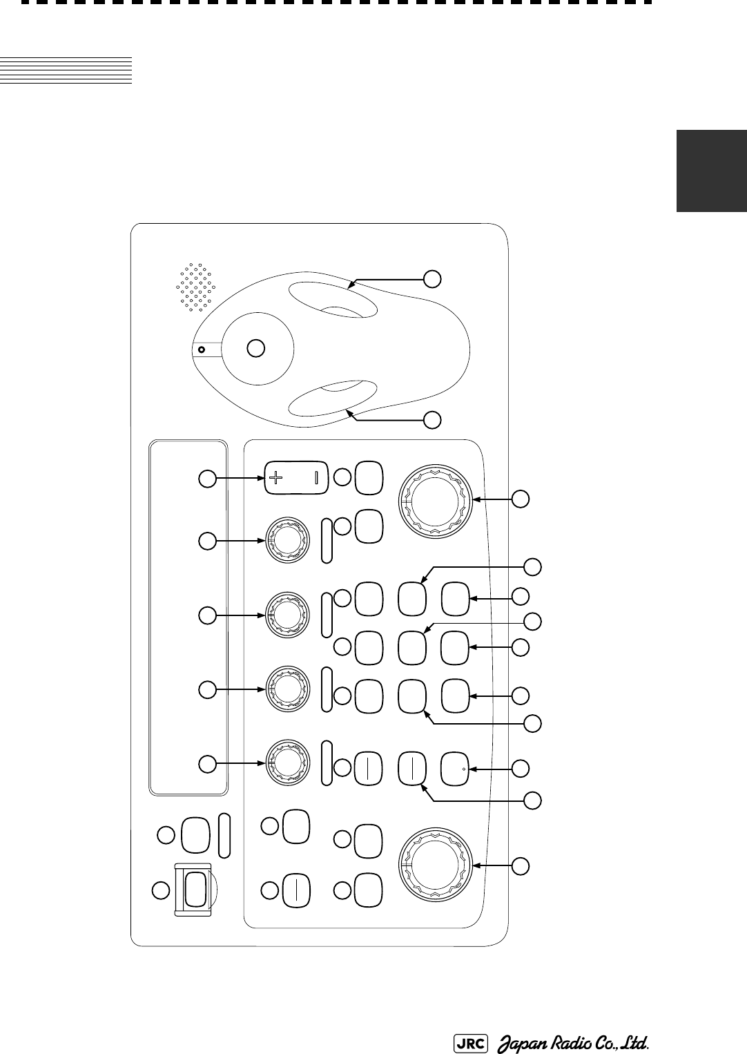
JMA-9100 Instruction Manual > 2.CONTROL PANEL KEYS and SOFTWARE BUTTONS> 2.2 NAMES AND FUNCTIONS OF
CONTROL PANEL KEYS
2-11
2
2.2 NAMES AND FUNCTIONS OF
CONTROL PANEL KEYS
The name of each button is described from the following page. See below.
12
3 4
5 6 7 8 9
10 11
12
14
15
1316 17 18 19
20 21 22 23
24 25 26 27
28
29 30
PWR
ACK
PWR FAIL
ALARM
ACK
EBL1 EBL2
PANEL
DAY
NIGHT
TGT
DATA
ACQ
MANUAL
ACQ
CANCEL
AIS/AR
PA
H L
OFF
DATA
OFF
USER
OPTION
1
OPTION
2
VRM1 VRM2
TUNE RAIN SEA GAIN
POWER
TX
STBY
T/R
VECT
RANGE

2-12
JMA-9100 Instruction Manual > 2.CONTROL PANEL KEYS and SOFTWARE BUTTONS > 2.2 NAMES AND FUNCTIONS OF
CONTROL PANEL KEYS
[POWER] (Power supply) switch
The lamp is lit and the equipment is activated.
If this switch is pressed while the equipment is running, the power of the equipment is
shut down.
→3.1.1 on page 3-2
[PWR ACK] (Power alarm acknowledgement) key
Use this function to acknowledge the alarm when power supply abnormality occurs.
To enable this key, an external battery (separate power from normal AC) is required.
[TX/STBY] (Transmission/Standby) key
When the [POWER] switch is pressed, the "STANDBY" message is displayed in the
top-left corner of the screen in about 3 minutes. If this key is pressed, transmission
starts. If this key is pressed during transmission, the equipment is set to a standby state.
→3.1.1 on page 3-2
[ALARM ACK] (Alarm acknowledgement) key
Use this function to acknowledge alarms such as failure alarm, approaching target alarm,
and collision alarm.
By pressing this key at the occurrence of an alarm, the alarm sound can be stopped.
If multiple alarms occur, press this key same time as the alarms.
→3.2.7 on page 3-12
[TUNE] (Tuning) dial
Use his function to tune a transmitter.
The mode is switched to manual/automatic whenever this dial is pressed.
→3.2.3 on page 3-7
[RAIN] (Rain / snow clutter suppression) dial
This function suppresses rain / snow clutters.
To increase the effect of suppression, turn the dial clockwise.
The mode can be switched to manual or automatic by pressing the dial.
→3.2.6 on page 3-11
[SEA] (Sea clutter suppression) dial
This function suppresses sea clutter.
To increase the effect of suppression, turn the dial clockwise.
The mode can be switched to manual or automatic by pressing the dial.
→3.2.5 on page 3-9
1
2
3
4
5
6
7

JMA-9100 Instruction Manual > 2.CONTROL PANEL KEYS and SOFTWARE BUTTONS> 2.2 NAMES AND FUNCTIONS OF
CONTROL PANEL KEYS
2-13
2
[GAIN] (Gain/pulse length) dial
This function adjusts the reception sensitivity of the radar.
To increase the sensitivity, turn the dial clockwise.
The transmission pulse width can be switched by pressing the dial.
gain→3.2.4 on page 3-8
pulse width→3.4.2 on page 3-24
[RANGE +/-] (Range switching) key
This function switches the range.
Press [+] to increase the observation range.
Press [-] to reduce the observation range.
→3.2.2 on page 3-6
[EBL1] (Electronic Bearing Line 1) key
Use this function to display and select EBL1.
If the key is pressed for 2 seconds or more, the menu for setting EBL1 is displayed.
→4.1.3 on page 4-3
[EBL2] (Electronic Bearing Line 2) key
Use this function to display and select EBL2.
If the key is pressed for 2 seconds or more, the menu for setting EBL2 is displayed.
→4.1.3 on page 4-3
[EBL] (Electronic Bearing Line) dial
This function rotates the azimuth of the EBL that is selected in EBL1/2.
By pressing the dial, the selected EBL can be switched to Center fixing → Floating →
Center fixing.
→4.1.3 on page 4-3
[VRM1] (Variable Range Marker 1) key
This function selects VRM1. The On/Off and dial use right are switched.
→ on page 4-6
[VRM2] (Variable Range Marker 2) key
This function selects VRM2. The On/Off and dial use right are switched.
→ on page 4-6
8
9
10
11
12
13
14

2-14
JMA-9100 Instruction Manual > 2.CONTROL PANEL KEYS and SOFTWARE BUTTONS > 2.2 NAMES AND FUNCTIONS OF
CONTROL PANEL KEYS
[VRM] (Variable Range Marker) dial
This function changes the range of the VRM that is selected by VRM1/2.
By pressing the dial, the parallel line cursor function can be switched to Operation →
Fixed → Off → Operation.
→ on page 4-6
[T/R VECT] (True vector display / Relative vector display) key
This function switches the display mode (true/relative) of the tracked target and AIS
target vector.
→5.1.6 on page 5-13
[TGT DATA] (Target data display) key
This function displays the digital data of the tracked target or AIS target at the cursor
position.
the tracked target →5.2.3 on page 5-17
the AIS target →5.3.5 on page 5-28
[ACQ MANUAL] (Manual acquisition) key
This function enables manual acquisition of the target at the cursor position.
→5.2.1 on page 5-14
[ACQ CANCEL] (Tracked target cancellation) key
This function cancels the symbol and vector of the target that is being tracked and stops
the tracking of the target.
If this key is pressed for 2 seconds or more, all the targets that are being tracked are
cancelled.
→5.2.2 on page 5-16
[DAY/NIGHT] (Day/night mode) key
This function switches the color and brightness of the screen that was preset.
→3.4.12 on page 3-35
[AIS/TT] (AIS On/Off) key
This function switches the AIS function to ON/OFF when the AIS function is enabled.
→5.3.2 on page 5-26
[HL OFF] (Ship's heading line Off) key
HL (ship's heading highlight line) can be set to Off only while this key is pressed.
→3.4.10 on page 3-34
15
16
17
18
19
20
21
22

JMA-9100 Instruction Manual > 2.CONTROL PANEL KEYS and SOFTWARE BUTTONS> 2.2 NAMES AND FUNCTIONS OF
CONTROL PANEL KEYS
2-15
2
[DATA OFF] (DATA Off) key
This function sets the graphics other than HL, range ring, EBL, and VRM to OFF
temporarily while this key is pressed.
→3.4.11 on page 3-34
[PANEL] (Operator panel brilliance) key
This function adjusts the lighting brilliance of various switches and dial positions on the
operator panel. The brightness changes cyclically whenever this key is pressed.
→3.4.13 on page 3-35
[USER] key
By pressing this key, the signal processing setting that is preset can be called.
The setting changes to FUNC OFF ==> FUNC1 ==> FUNC2 ==> FUNC3 ==>
FUNC4 whenever this key is pressed.
If this key pressed for 2 seconds or more, the function setting menu is displayed.
→3.9 on page 3-111
[OPTION1] key
By pressing this key, the pre-registered menu position can be directly displayed.
At factory shipment, the calling of [Main Menu] is assigned.
→3.8.7 on page 3-103
[OPTION2] key
By pressing this key, the pre-registered menu position can be directly displayed.
At factory shipment, the calling of [Sub Menu] is assigned.
→3.8.7 on page 3-103
Track ball
This function moves the cursor mark to any position. Use this function for setting in
each mode.
Use this function to specify a center position of floating EBL and an off-center position.
→3.3.1 on page 3-14
[Track ball left button]
Use this function to confirm menu selection and numeric value input.
[Track ball right button]
Use this function to reset menu selection and numeric value input.
[BRILL] (Brilliance dial)
This dial is provided at the right of the monitor. Use this function to adjust the brilliance
of the monitor.
→3.2.1 on page 3-6
23
24
25
26
27
28
29
30
31
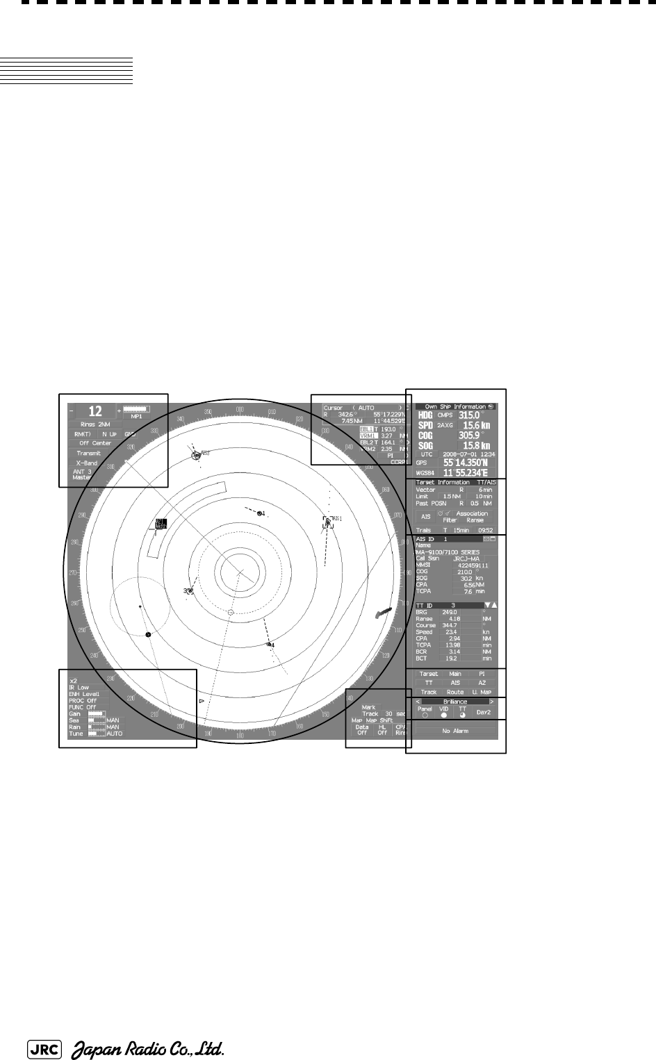
2-16
JMA-9100 Instruction Manual > 2.CONTROL PANEL KEYS and SOFTWARE BUTTONS> 2.3 FUNCTIONS OF SOFTWARE
BUTTONS
2.3 FUNCTIONS OF SOFTWARE
BUTTONS
In this radar, the frequently used functions can be directly set from the screen
without opening the menu by using the software buttons on the screen for quick
handling. The screen is divided into a number of areas and each area is named.
The name of each button is described from the next page. The function can be
used by left-clicking while setting the arrow cursor on the button position.
PPI
Upper left
of the display
Lower left
of the display
Upper right
of the display
Lower right
of the display
Own ship's
information
Digital information
Target
tracking (TT) /
AIS information
Menu
Brilliance /
Display information
Alarm
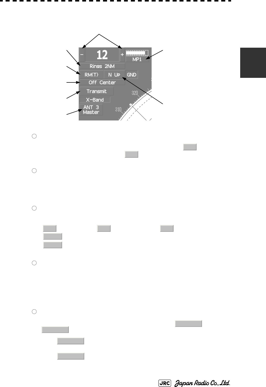
JMA-9100 Instruction Manual > 2.CONTROL PANEL KEYS and SOFTWARE BUTTONS> 2.3 FUNCTIONS OF SOFTWARE
BUTTONS
2-17
2
Upper left of the display
Range scale switching
To increase the observation range scale (maximum 96NM), click and to reduce
the range (minimum 0.125NM), click .
Range rings display On / Off
The display of range rings are set to On / Off whenever this button is clicked.
When the display is set to On, the interval of the fixed range marker is displayed.
Motion mode true / relative switching
The screen motion mode is switched whenever the button is clicked.
(true motion) ⇒ (relative motion) ⇒
indicates that the radar trails is a relative trail.
indicates that the radar trails is a true trail.
Off center switching
If this button is clicked, the cursor is moved, and left-clicked, the ship's position can be
moved to the cursor position. The moving range is within 66% of the radius.
If the button is clicked for 2 seconds, the off-center is set to Off and the ship's position is
returned to the center of the screen.
Transmission / standby switching
At expiration of the pre-heat time after the power is turned on, changes to
.
:Indicates a standby state. If this button is clicked in this state, the
equipment is set to a transmission state.
:Indicates a transmission state. If this button is clicked in this state,
the equipment is set to a standby state.
① Range scale switching
② Range rings display
On /Off
③ Motion mode true / relative
switching
④ Off center switching
⑤Transmission / Standby
switching
⑥ Interswitch connection
change
⑦ Transmission pulse length
switching
⑧Azimuth display mode
switching
1
+
-
2
3
TM
RM TM
RM(R)
RM(T)
4
5
Preheat
Standby
Standby
Transmit
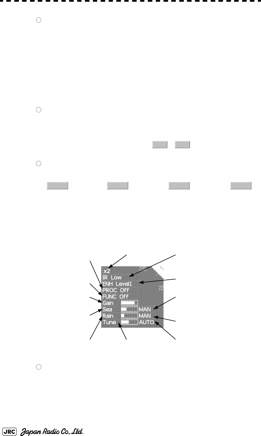
2-18
JMA-9100 Instruction Manual > 2.CONTROL PANEL KEYS and SOFTWARE BUTTONS > 2.3 FUNCTIONS OF SOFTWARE
BUTTONS
Interswitch connection change
This button is displayed when the interswitch is connected. This button indicates the
connection status of the scanner unit that is connected to the indicator.
If the button is clicked in the transmission standby state, the menu for changing the
connection state between the scanner unit and the indicator is displayed. The connection
state of the scanner unit and indicator cannot be changed unless the master indicator is in
a standby state.
Refer to the Appendix A NQE-3141 Interswitch Unit Interswitch (Optional) Instruction
Manual that is attached for the setting method. This button is not displayed if the
interswitch is not connected.
Transmission pulse length switching
The transmission pulse length is switched whenever this button is clicked. Three types
of pulses are available, short pulse (SP), middle pulse (MP), and long pulse (LP). The
pulse length and repetition frequency vary even for the same short pulse, according to
the range that is used and it is displayed as , .
Azimuth display mode switching
The azimuth display is switched whenever this button is clicked.
(Head Up) ⇒ (North Up) ⇒ (Course Up) ⇒
If the button is clicked for 2 seconds, the GYTO Setting menu is displayed.
Lower left of the display
Double zoom switching
Use this function to enlarge to double the size the display screen of the position specified
by the cursor. If this button is clicked, the zoom mode is set. When the cursor is moved
to the radar screen and left-clicked, the screen is enlarged to double the size so that the
middle of the cursor and the own ship's position is set to the center of the screen. This
function cannot be used when the range is 0.125NM.
6
7
SP1 SP2
8
H Up N Up C Up H Up
③Target enhance (ENH)
mode switching
④Radar video processing (PROC)
mode switching
⑤Function (FUNC)
mode switching
①Double zoom switching
②Interference rejection (IR)
mode switching
⑦Sea clutter suppression (Sea)
adjustment
⑧Rain / snow clutter
suppression (Rain)
adjustment ⑨Tune adjustment
⑩Sea clutter suppression (Sea)
mode switching
⑪Rain and snow clutter
suppression (Rain)
mode switching
⑥Gain adjustment
⑫Tune mode switching
1

JMA-9100 Instruction Manual > 2.CONTROL PANEL KEYS and SOFTWARE BUTTONS> 2.3 FUNCTIONS OF SOFTWARE
BUTTONS
2-19
2
Interference rejection (IR) mode switching
The interference rejection mode is switched whenever this button is clicked.
⇒ ⇒ ⇒ ⇒
Target enhance (ENH) mode switching
The target enhance mode is switched whenever this button is clicked.
⇒ ⇒ ⇒ ⇒
Radar video processing (PROC) mode switching
The radar video processing mode is switched whenever this button is clicked.
⇒ ⇒ ⇒
⇒ ⇒ ⇒
Function (FUNC) mode switching
The function mode is switched whenever this button is clicked.
⇒ ⇒ ⇒
⇒ ⇒
If the button is clicked for 2 seconds, the function registration menu (User Function
Setting) is opened.
,, and Gain, Sea clutter suppression(Sea)、Rain / snow
clutter suppression (Rain), Tune adjustment (Tune)
Adjust the gain, sea clutter suppression, rain / snow clutter suppression and tune using
the track ball.
If the button is clicked on, the adjustment value is shown at the upper-right of the cursor.
Make adjustments by moving the track ball to the left and right. Determine the
adjustment by left-clicking.
, and Sea clutter suppression (Sea) mode, Rain and snow clutter
suppression (Rain) mode, and Tune mode switching
Use these functions to switch to the manual or automatic mode of sea clutter
suppression, rain and snow clutter suppression, and tune. The bar on the left side
indicates the position of the dial.
The mode is switched to (manual) / (automatic) whenever the
button is clicked. If rain and snow clutter suppression is switched to an automatic mode,
sea clutter suppression is switched to an automatic mode also.
2
IR Off IR Low IR Meddle IR High IR Off
3
ENH Off
ENH Level1 ENH Level2
ENH Level3 ENH Off
4
PROC Off
3Scan CORREL 4Scan CORREL 5Scan CORREL
Remain Peak Hold PROC Off
5
FUNC Off Coast Deep Sea Fishnet
Storm FUNC Off
6
7
8
9
10
11 12
MAN AUTO
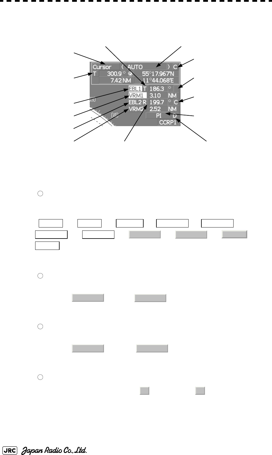
2-20
JMA-9100 Instruction Manual > 2.CONTROL PANEL KEYS and SOFTWARE BUTTONS > 2.3 FUNCTIONS OF SOFTWARE
BUTTONS
Upper Right of the display
Cursor mode switching
The mode of the function that uses the cursor is switched whenever this button is
pressed.
⇒ ⇒ ⇒ ⇒ ⇒
⇒ ⇒ ⇒ ⇒ ⇒
Mark font / line pattern switching
This function switches a mark font / line pattern. If this button is clicked while the cursor
mode is (mark) or (line), the mark font / line pattern is
changed.
Mark color / line color switching
This function switches a mark color / line color. If this button is clicked while the cursor
mode is (mark) or (line), the mark color / line color is
changed.
Cursor bearing numeric value display true / relative switching
The bearing numeric value display (true bearing) / (relative bearing) of the
cursor is switched whenever this button is clicked.
④Cursor bearing
numeric value display
true / relative switching
⑤EBL1 adjustment
⑥VRM1 adjustment
⑪EBL1 starting point
mode switching
①Cursor mode switching
⑫EBL2 starting point
mode switching
⑬Parallel index line
setting
⑭Parallel index line
starting point mode
switching
⑩EBL2 numeric value indication
true / relative switching
③Mark color / line color
switching
⑧VRM2 adjustment
⑦EBL2 adjustment
⑨EBL1 numeric value indication
true / relative switching
②Mark font / line pattern
switching
1
AUTO ACQ TT
ACT AIS
TGT Data CNCL TT
DEACT AIS
CNCL Data
□
-------
Property
AUTO
2
□
-------
3
□
-------
4
T
R

JMA-9100 Instruction Manual > 2.CONTROL PANEL KEYS and SOFTWARE BUTTONS> 2.3 FUNCTIONS OF SOFTWARE
BUTTONS
2-21
2
, , and EBL1 / 2 and VRM1 / 2 adjustment
These functions set the EBL1 , VRM1 , EBL2 , and VRM2 displays to On / Off and
acquire the operation right.
If the button is clicked on, the operation right is acquired. Make adjustments by moving
the track ball to the left and right Determine the adjustment by left-clicking.
and EBL1, EBL2 numeric value true / relative switching
The EBL1 / 2 bearing numeric value display (true bearing) / (relative
bearing) is switched whenever the button is clicked.
If the button is clicked for 2 seconds, the EBL / Cursor Setting menu is displayed.
and EBL1 / EBL2 starting point mode switching
The EBL starting point is set to CCRP or any position on the radar screen whenever this
button is clicked.
⇒ ⇒ ⇒
Parallel index line setting
This function sets the parallel index line display to On / Off and acquires the operation
right.
If this button is clicked, the operation right is acquired and the menu is opened. After
setting, determine the setting by left-clicking.
Parallel index line starting point mode switching
The parallel index line starting point is set to CCRP or any position on the radar screen
whenever this button is clicked.
In the same way as for the EBL starting point, three options are available, : Center,
: Screen Fix, and : L/L Fix.
:Center The starting point is fixed to the CCRP position.
:Screen Fix The starting point is set to the cursor position. If left-
clicked subsequently, the starting position is fixed to
the cursor position.
:L/L Fixi
i. is enabled only when a navigator is connected.
The starting point is set to the cursor position. If
left-clicked subsequently, the starting position is
fixed to the latitude / longitude of the cursor.
(Connection of a navigator is necessary.) If the
starting point is moved outside of the screen, the
operation is reset automatically and the starting
point returns to the CCRP position.
567
8
9
10
TR
11 12
_C D _
_
C
D
D
13
14
_
C D
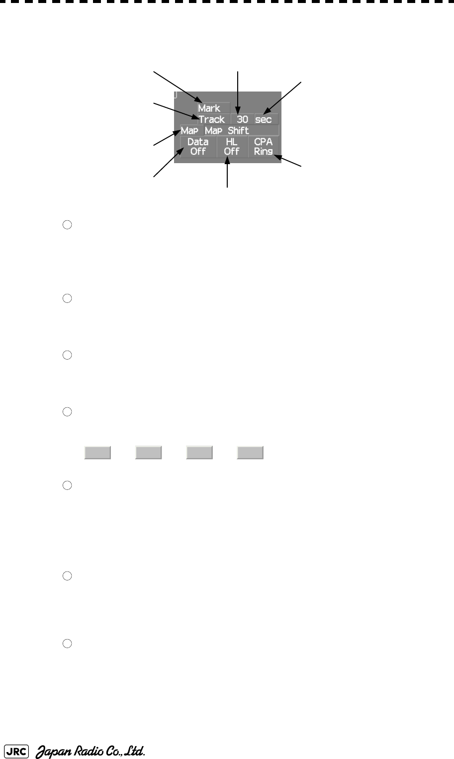
2-22
JMA-9100 Instruction Manual > 2.CONTROL PANEL KEYS and SOFTWARE BUTTONS > 2.3 FUNCTIONS OF SOFTWARE
BUTTONS
Lower right of the display
Mark color switching
The color of the mark is switched whenever this button is clicked.
If the button is clicked for 2 seconds, the Mark Setting menu is opened.
Own ship's track color switching
The own ship's track color is switched whenever this button is clicked.
Own ship's track interval switching
The own ship's track interval is switched whenever this button is clicked.
Own ship's track interval unit switching
The unit of the own ship's track interval is switched whenever this button is clicked.
⇒ ⇒ ⇒
Map display On / Off
The map display is set to On / Off whenever this button is clicked.
Map information must be inserted in the card slot of the radar process unit in advance.
If the button is clicked for 2 seconds, the Map Setting menu is opened.
Graphic display Off
While the button is clicked, the graphic display other than VRM, EBL, HL, a cursor, and
range rings on the radar screen is cleared temporarily.
Ship's heading line Off
The ship's heading line (HL) display is set to Off while this button is clicked.
Since the ship's heading line is cleared while the button is clicked, the target in the ship's
heading bearing can be clearly seen.
③Own ship's track interval
switching
⑤Map display
On / Off
⑥Graphic display Off
⑦Ship's heading line Off
④Own ship's track interval unit
switching
⑧CPA ring display
On / Off
①Mark color switching
② Own ship’s track color
switching
1
2
3
4
sec min NM sec
5
6
7
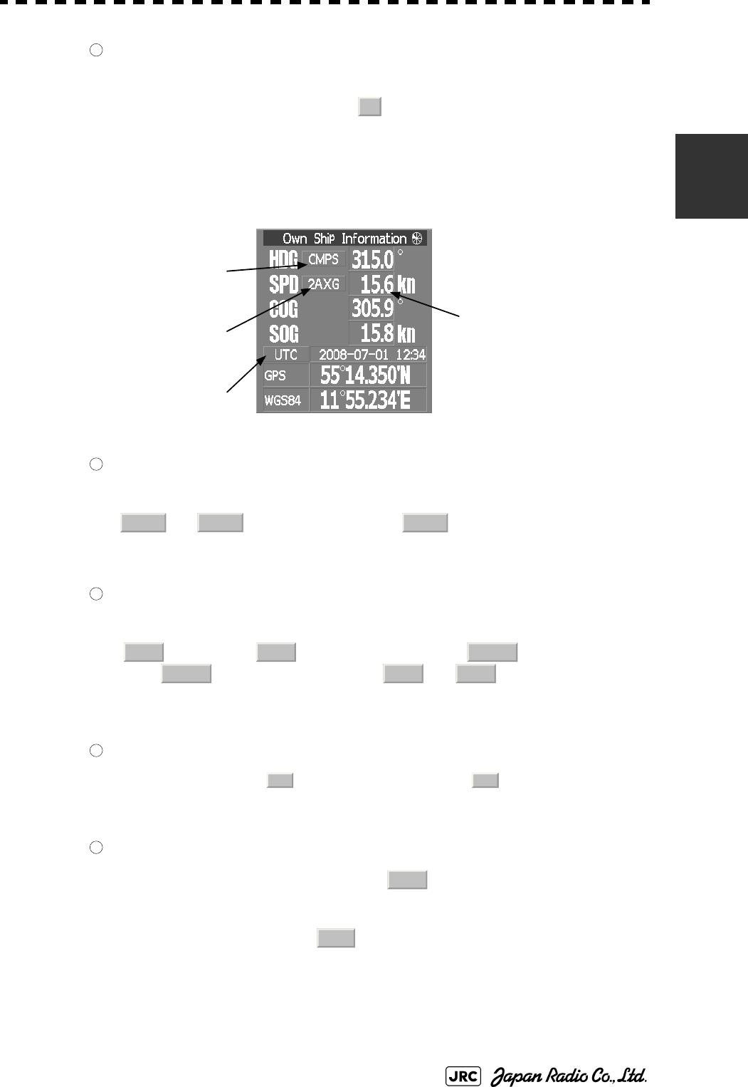
JMA-9100 Instruction Manual > 2.CONTROL PANEL KEYS and SOFTWARE BUTTONS> 2.3 FUNCTIONS OF SOFTWARE
BUTTONS
2-23
2
CPA ring display On / Off
The CPA ring display is switched to On / Off whenever the button is clicked.
When the target vector display mode is (true vector), the CPA ring cannot be set to
On.
Own ship's information
Heading device switching
The heading device is switched whenever this button is clicked.
⇒ (Electronic compass)⇒
When the selected heading device is not connected to the equipment, an alarm is issued.
Speed sensor switching
The speed sensor is switched whenever the button is clicked.
(Manual) ⇒ (Single-axis water log) ⇒ (Dual-axis water
log) ⇒ (Dual-axis ground log) ⇒ ⇒
When the selected speed device is not connected to the equipment, an alarm is issued.
Time display mode switching
The time display mode (universal time clock) / (local mean time) is
switched whenever this button is clicked.
Manual own ship's speed setting
When selection of the speed sensor is set to , enter the own ship's speed
manually.
If this button is clicked, the numeric value input screen is opened. After setting a value,
determine the entry by clicking .
8
T
① Heading device
switching
②Speed sensor
switching
③Time display mode
switching
④Manual own ship's speed
setting
1
GYRO CMPS GYRO
2
MAN LOG 2AXW
2AXG GPS MAN
3
UTC
LMT
4
MAN
ENT
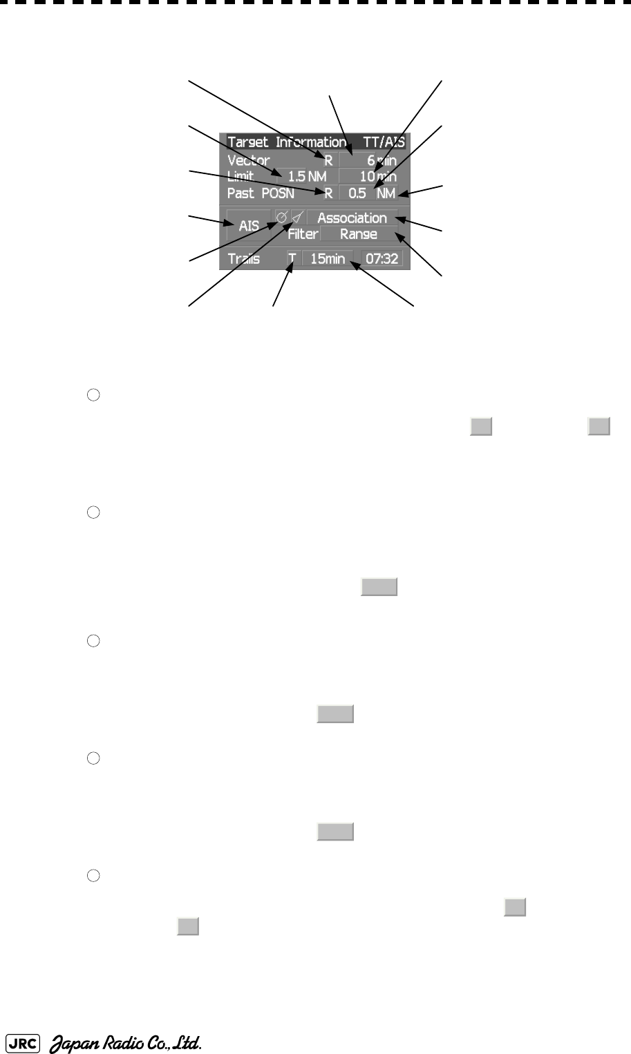
2-24
JMA-9100 Instruction Manual > 2.CONTROL PANEL KEYS and SOFTWARE BUTTONS > 2.3 FUNCTIONS OF SOFTWARE
BUTTONS
Target tracking (TT) / AIS information
Target vector display true / relative switching
The tracked target / AIS target vector display is switched to (true vector) /
(relative vector) whenever this button is clicked.
This setting is switched together with the past position display true / relative switching.
Target vector length setting
Set a vector length of the tracked target / AIS target.
If this button is clicked, the numeric value input screen is opened. After setting the
length, determine the setting by clicking .
CPA limit setting
Set a CPA limit.
If this button is clicked, the numeric value input screen is opened. After setting the limit,
determine the setting by clicking .
TCPA limit setting
Set a TCPA limit.
If this button is clicked, the numeric value input screen is opened. After setting the limit,
determine the setting by clicking .
Past position display true / relative switching
The tracked target / AIS target past position display is switched to (true past
position) / (relative past position) whenever the button is clicked.
This setting is switched together with the target vector display true / relative switching.
⑥Past position display
interval switching
⑪Association
On / Off
⑭Radar trails display time
switching
⑬Radar trails display
true / relative switching
①Target vector display
true / relative switching ②Target vector length setting
⑤Past position display
true / relative switching ⑦Past position display
interval unit switching
④TCPA limit setting
③CPA limit setting
⑧AIS
On / Off
⑩AIS target symbol display
On / Off
⑨Tracked target symbol
display On / Off ⑫AIS filter mode switching
1
TR
2
ENT
3
ENT
4
ENT
5
T
R

JMA-9100 Instruction Manual > 2.CONTROL PANEL KEYS and SOFTWARE BUTTONS> 2.3 FUNCTIONS OF SOFTWARE
BUTTONS
2-25
2
Past position display interval switching
The past position display interval is switched whenever the button is clicked.
Past position display interval unit switching
The past position display interval unit is switched whenever the button is clicked.
⇒ ⇒
AIS On / Off
The AIS display is switched to On / Off whenever the button is clicked.
Tracked target symbol display On / Off
The tracked target symbol display is switched to On / Off whenever the button is
clicked. Use this function to avoid confusion with the AIS symbol.
AIS target symbol display On / Off
The AIS target symbol display is switched to On / Off whenever the button is clicked.
Use this function to avoid confusion with the tracked target symbol.
Association On / Off
The tracked target / AIS target association is switched to On / Off whenever the button is
clicked.
AIS filter mode switching
The AIS filter is switched whenever the button is clicked.
⇒ ⇒ ⇒
Radar trails display true / relative switching
Radar trails are switched to (true motion trail) / (relative motion trail)
whenever this button is clicked.
This setting is restricted by the radar display motion mode.
In relative motion display mode (RM), switching to / is possible.
In true motion display mode (TM), only can be set.
Radar trails display time switching
The radar trails display time is switched whenever the button is clicked.
If the time does not reach the radar trails time that was set, the remaining time is
displayed on the right-hand side.
If the button is clicked for 2 seconds, the RADAR Trails Setting menu is opened.
6
7
min NM min
8
9
10
11
12
Range Sector Zone Range
13
T
R
T
R
T
14
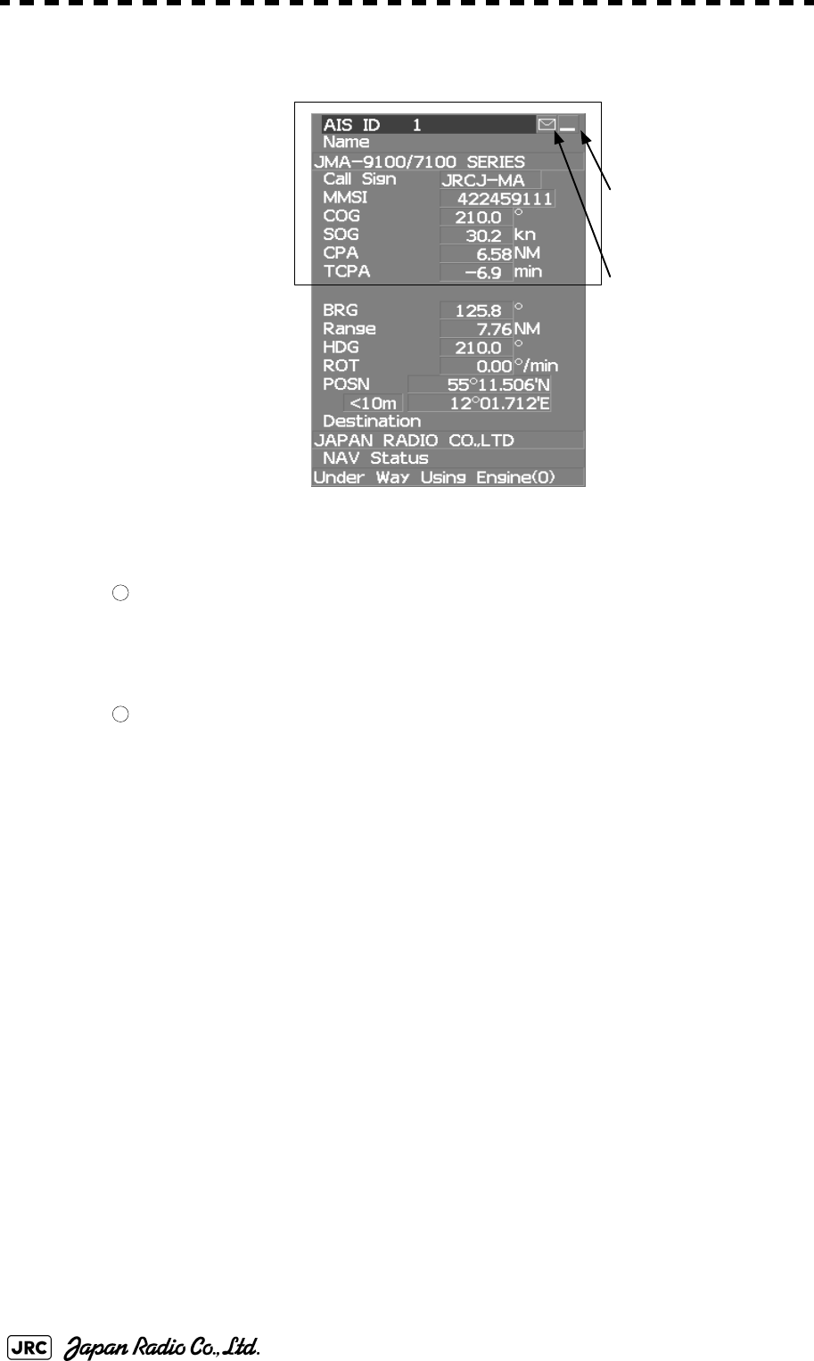
2-26
JMA-9100 Instruction Manual > 2.CONTROL PANEL KEYS and SOFTWARE BUTTONS > 2.3 FUNCTIONS OF SOFTWARE
BUTTONS
Numeric information: AIS target information
Detail / simple display switching
This function switches the display mode to detail / simple display when AIS target
information is displayed.
Unread message display
When there is an unread message from the AIS target that is displayed, the message is
displayed. If this button is clicked, the message is displayed.
①:Detail / simple
display switching
②:Unread message
display
simple display
1
2
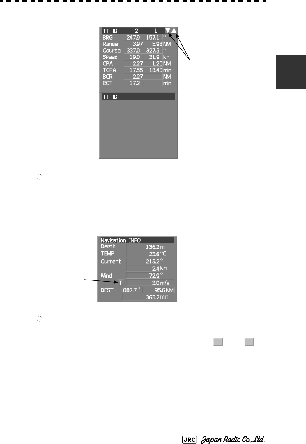
JMA-9100 Instruction Manual > 2.CONTROL PANEL KEYS and SOFTWARE BUTTONS> 2.3 FUNCTIONS OF SOFTWARE
BUTTONS
2-27
2
Numeric information: Tracked target information
Tracked target numeric value indication scroll
This function scrolls the target numbers that are indicated in the tracked target
information.
Numeric information: Navigation information
Wind direction / speed numeric value indication true / relative
switching
The wind direction / speed numeric value indication is switched to (true) /
(relative) whenever this button is clicked.
①Tracked target
numeric value indication
scroll
1
①Wind direction / speed
numeric value indication
true / relative switching
1
T R
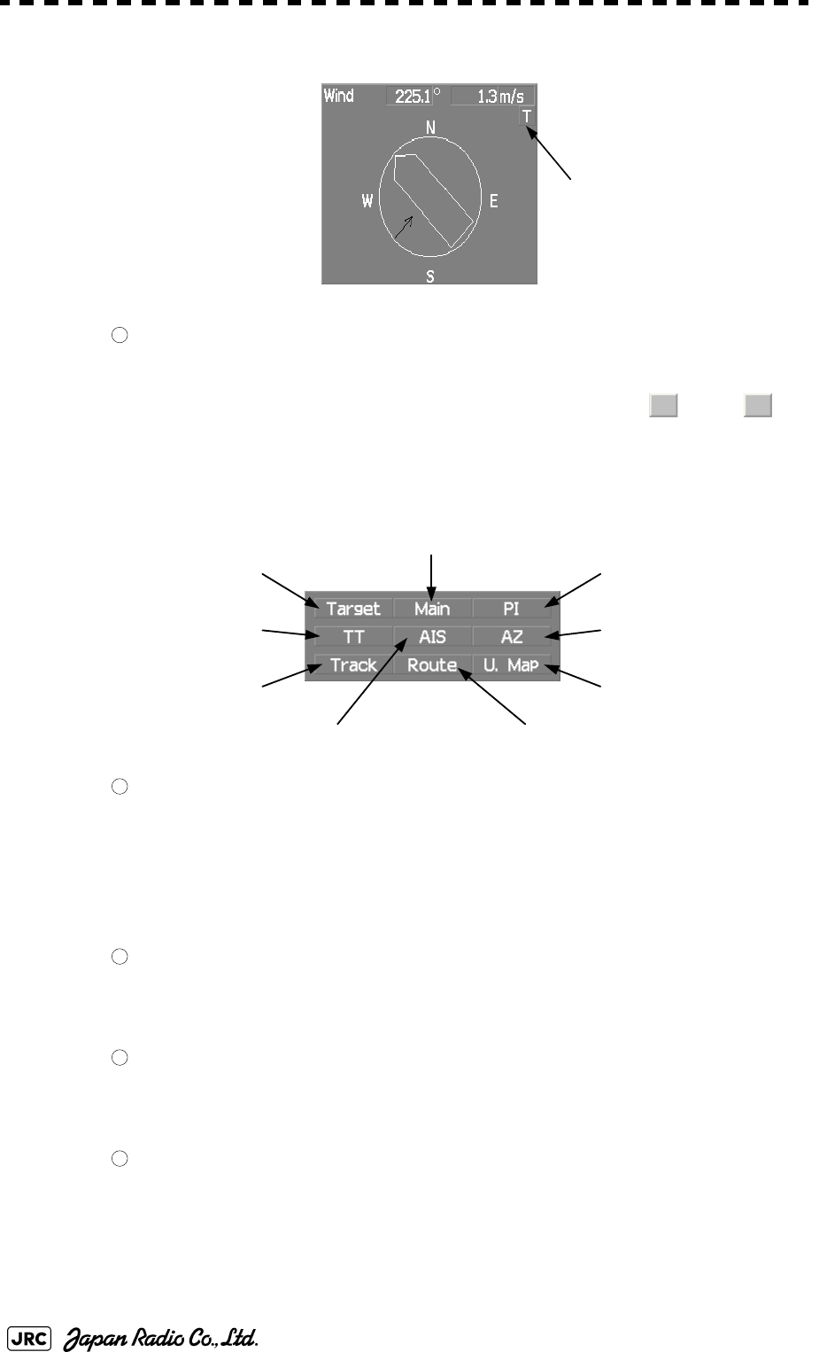
2-28
JMA-9100 Instruction Manual > 2.CONTROL PANEL KEYS and SOFTWARE BUTTONS > 2.3 FUNCTIONS OF SOFTWARE
BUTTONS
Graph information: Wind direction / speed
Wind direction / speed numeric value indication true / relative
switching
The wind direction / speed numeric value indication is switched to (true) /
(relative) whenever this button is clicked.
Menu
Digital information display
If this button is clicked while the menu screen is open, the menu is closed and control
returns to the digital information display.
This function switches between the tracked target / AIS target display and navigation
information or the course bar, and so on.
Target Tracking (TT) menu
If this button is clicked, the TT Menu is opened.
Own track menu
If this button is clicked, the Own Track Menu is opened.
Main menu
If this button is clicked, the Main Menu is opened.
①Wind direction / speed
numeric value indication
true / relative switching
1
T R
① Digital information display
② Target Tracking (TT) menu
⑨ User map menu
⑦ Parallel index line menu
③ Own ship’s track menu
⑧Automatic acquisition /
activation zone (AZ) menu
⑥ Route menu
④Main menu
⑤ AIS menu
1
2
3
4
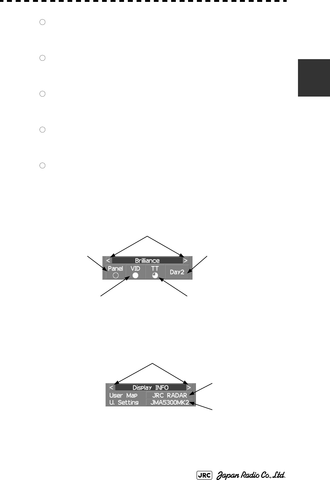
JMA-9100 Instruction Manual > 2.CONTROL PANEL KEYS and SOFTWARE BUTTONS> 2.3 FUNCTIONS OF SOFTWARE
BUTTONS
2-29
2
AIS menu
If the button is clicked, the AIS Menu is opened.
Route menu
If this button is clicked, the Route Menu is opened.
Parallel index line menu
If this button is clicked, the PI Menu is opened.
Automatic acquisition / activation zone menu
If this button is clicked, the AZ Menu is opened.
User map menu
If the button is clicked, the User Map Menu is opened.
Brilliance
Display information
5
6
7
8
9
①Display item switching
②Panel lighting brilliance
switching
③Radar video brilliance
switching
⑤Day / night mode
switching
④Tracked target / AIS target symbol
brilliance switching
⑦User setting load
⑥User map load
①Display item switching
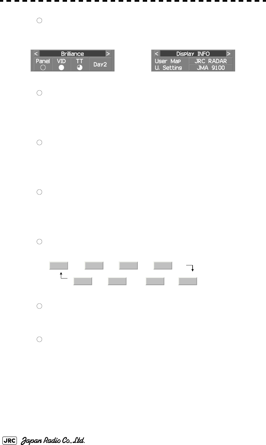
2-30
JMA-9100 Instruction Manual > 2.CONTROL PANEL KEYS and SOFTWARE BUTTONS > 2.3 FUNCTIONS OF SOFTWARE
BUTTONS
Display item switching
The brilliance adjustment screen and display information setting screen interchange
whenever this button is clicked.
Panel lighting brilliance switching
This function enables the setting of the brilliance of the lighting of the control panel.
The brilliance changes whenever this button is clicked. Five levels of settings are
available.
Radar video brilliance switching
Adjust the brightness of the radar video (echo).
The brilliance changes whenever this button is clicked. Four levels of settings are
available.
Tracked target / AIS target symbol brilliance switching
Use this function to adjust the brilliance of the tracked target / AIS target symbol.
The brilliance changes whenever this button is clicked. Five levels of settings are
available.
Day / night mode switching
The day / night mode is switched whenever this button is clicked.
→ → →
← ← ←
User map load
If this button is clicked, the user created map read menu is opened.
User setting load
If this button is clicked, the user setting read menu is opened.
1
⇔
2
3
4
5
Day1 Day2 Day3 Dusk
Day2 Day3 Dusk Night
6
7
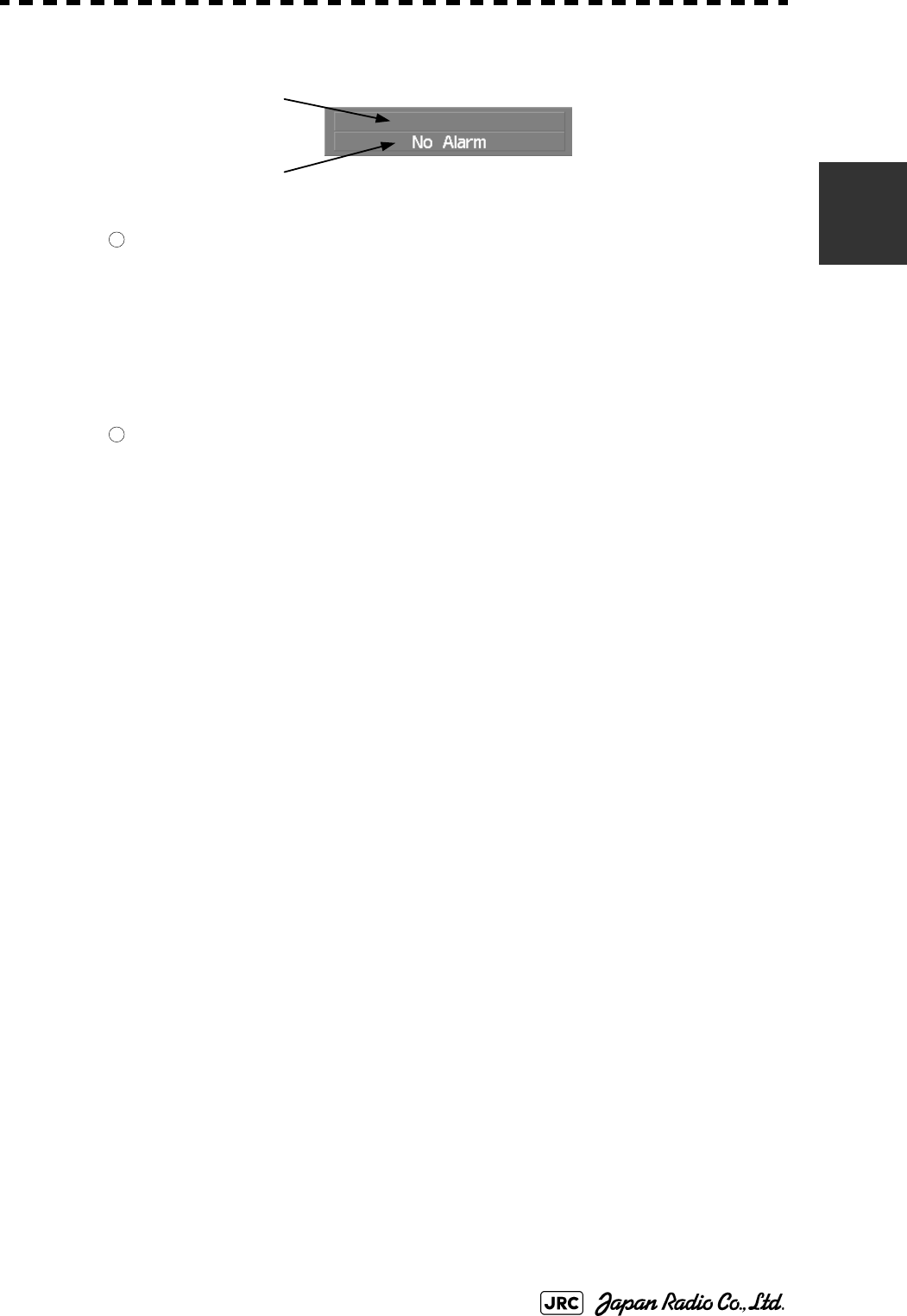
JMA-9100 Instruction Manual > 2.CONTROL PANEL KEYS and SOFTWARE BUTTONS> 2.3 FUNCTIONS OF SOFTWARE
BUTTONS
2-31
2
Alarm
Alarm acknowledgment
If this button is clicked, the buzzer sound of the alarm that is currently issued is stopped
and the alarm lamp stops blinking. If multiple alarms are issued, the next alarm to be
acknowledged is displayed.
If the button is clicked, the alarm displayed on the top is acknowledged.
The alarms that are currently issued are displayed at the bottom one by one.
Error log display
If this button is clicked, the error log is display.
①Alarm acknowridgement
②Error log display
1
2

2-32
JMA-9100 Instruction Manual > 2.CONTROL PANEL KEYS and SOFTWARE BUTTONS > 2.3 FUNCTIONS OF SOFTWARE
BUTTONS
BASIC OPERATION
3.1 OPERATION FLOW ...............................................................................3-1
3.1.1 Power ON and Start the System ....................................................3-2
3.1.2 Observe and Adjust Video ..............................................................3-4
3.1.3 Acquire and Measure Data .............................................................3-4
3.1.4 Display and Measure with Reference to CCRP ............................3-4
3.1.5 End the Operation and Stop the System .......................................3-5
3.2 OBSERVE AND ADJUST VIDEO ..........................................................3-6
3.2.1 Adjust Monitor Brilliance [BRILL] ..................................................3-6
3.2.2 Change Observation Range [RANGE+/-] ......................................3-6
3.2.3 Tune ..................................................................................................3-7
3.2.4 Adjust Gain [GAIN] .........................................................................3-8
3.2.5 Suppress Sea Clutter [SEA] ..........................................................3-9
3.2.6 Suppress Rain/Snow Clutter [RAIN] ...........................................3-11
3.2.7 Reset Alarm Buzzer [ALARM ACK] .............................................3-12
3.2.8 To get the appropriate image that targets can be easily observed ...3-13
3.3 OPERATION PROCEDURES ..............................................................3-14
3.3.1 Move Cross Cursor Mark by Trackball ........................................3-14
SECTION 3
BASIC OPERATION
3.3.2 Operate Software Buttons ...........................................................3-15
3.3.3 Basic Menu Operation ..................................................................3-16
3.3.4 Operation on Numeric Value, Latitude / Longitude and Character
Input menu .....................................................................................3-17
3.3.5 Overview of Menu Structure .........................................................3-22
3.4 GENERAL RADAR OPERATION ........................................................3-23
3.4.1 Interference Rejection (IR) ............................................................3-23
3.4.2 Switch Transmitter Pulse Length [GAIN] ....................................3-24
3.4.3 Target Enhance (ENH) ..................................................................3-25
3.4.4 Use Video Processing (PROC) .....................................................3-26
3.4.5 Switch Azimuth Display Mode (AZI MODE) ................................3-27
3.4.6 Switch True/Relative Motion Display Mode (TM/RM) .................3-28
3.4.7 Move Own Ship’s Display Position (Off Center) .........................3-29
3.4.8 Display Radar Trails (Trails) .........................................................3-30
3.4.9 Zoom (x2) .......................................................................................3-33
3.4.10 Hide/Display Range Rings [HL OFF] ...........................................3-34
3.4.11 Hide Graphics Information on Radar Display [DATA OFF] .......3-34
3.4.12 Switch Day/Night Mode [DAY/NIGHT] .........................................3-35
3.4.13 Adjust Operation Panel Brilliance [PANEL] ................................3-35
3.4.14 Set True Bearing ............................................................................3-36
3.4.15 Set Own Ship Speed .....................................................................3-36
3.4.16 Magnet Compass Correction (MAG Compass Setting) .............3-37
3.5 USE OWN SHIP'S TRACK ...................................................................3-39
3.5.1 Display Own Ship’s Track (Display Own Track) ......................3-39
3.5.2 Set Display Color of Own Ship's Track (Display Own Track Color) ..3-40
3.5.3 Save Own Ship's Track (Own Track Memory) ............................3-41
3.5.4 Cancel Saving of Own Ship's Track (Own Track Memory) ........3-41
3.5.5 Clear Own Ship's Track (Clear Own Track) ................................3-42
3.5.6 Use Expanded Own Ship's Track (Own Track Type) .................3-42
3.5.7 Use Water Depth Track (Water Depth Track) ..............................3-44
3.5.8 Use Water Temperature Track (Water TEMP Track) ..................3-45
3.5.9 Use Tidal Current Track (Current Vector Track) .........................3-46
3.6 DISPLAY USER MAP ...........................................................................3-47
3.6.1 Create User Map (Mark/Line) ........................................................3-47
3.6.2 Set User Map Display (Mark Display Setting) .............................3-50
3.6.3 Edit User Map (Edit User Map) .....................................................3-52
3.6.4 Correct Position on User Map (Shift User Map) .........................3-60
3.6.5 Save User Map ...............................................................................3-61
3.6.6 Set and Display Geodetic System (Geodetic) .............................3-65
3.7 USE ROUTE FUNCTION ......................................................................3-67
3.7.1 Display Route/Destination Mark (Select Route) .........................3-67
3.7.2 Edit Route (Set Route Sequence) ................................................3-68
3.7.3 Edit Route Make with Latitude and Longitude (Waypoint Input) .......3-75
3.7.4 Use Route Monitoring Function (Waypoint/Route Alarm) .........3-79
3.7.5 Method of Using Route .................................................................3-81
3.7.6 Detailed Route Settings ................................................................3-82
3.7.7 Clear Waypoint/Route Data (Clear WPT/Route Data) .................3-86
3.7.8 Operate Route Data File ................................................................3-87
3.8 APPLIED OPERATIONS ......................................................................3-91
3.8.1 Set Radar Signal Processing (Process Setting) .........................3-91
3.8.2 Set Radar Trails (RADAR Trails Setting) .....................................3-95
3.8.3 Set Scanner Unit (TXRX Setting) .................................................3-97
3.8.4 Set Cursor (Cursor Setting) ..........................................................3-98
3.8.5 Set Radar Display (Display Setting) ............................................3-99
3.8.6 Adjust Sound Volume (Buzzer Volume) ....................................3-102
3.8.7 Set User Option Keys [OPTION 1/2] ..........................................3-103
3.8.8 Set Navigation Data Display (Multi Window Setting) ...............3-105
3.8.9 AUTO Backup ..............................................................................3-110
3.9 USE FUNCTION KEY [USER] ...........................................................3-111
3.9.1 Operation Procedures .................................................................3-111
3.9.2 Function Setting Menu Items .....................................................3-112
3.9.3 Overview of Function Operations (User Function Setting) .....3-113
3.9.4 Overview of saved Function Setting Data .................................3-117
3.10 USE USER SETTING .........................................................................3-118
3.10.1 Save Operating State (Save User Setting) ................................3-118
3.10.2 Load Operating State (Load User Setting) ................................3-119
3.10.3 Delete Operating State (Delete User Setting) ...........................3-119
3.11 USING CARD .....................................................................................3-120
3.11.1 Operate File on the Card (File Manager) ...................................3-120
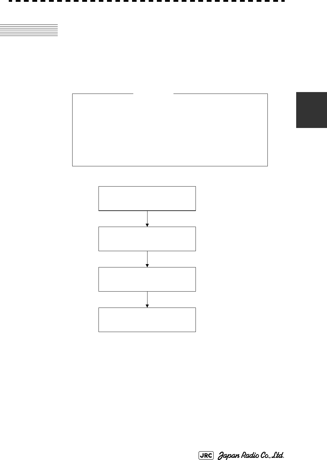
JMA-9100 Instruction Manual > 3.BASIC OPERATION > 3.1 OPERATION FLOW
3-1
3
3.1 OPERATION FLOW
Each operation is described in detail below.
• Do not put anything on the operation panel.
If you put anything hot on it, it may be deformed.
• Do not give any impact to the operation panel,
trackball, or controls.
Otherwise, any failure or damage may result.
Attention
POWER ON AND
START THE SYSTEM
OBSERVE AND
ADJUST VIDEO
ACQUIRE AND
MEASURE DATA
END THE OPERATION
AND STOP THE SYSTEM

3-2
JMA-9100 Instruction Manual > 3.BASIC OPERATION > 3.1 OPERATION FLOW
3.1.1 Power ON and Start the System
!
• A malfunction may occur if the power in the ship is
instantaneously interrupted during operation of the
radar. In this case, the power should be turned on
again.
• Wait for about 2 seconds before turning on the power again.
• Immediately after the radar is installed, at start of the system
after it has not been used for a long time, or after the
magnetron is replaced, preheat the equipment in the standby
state for 20 to 30 minutes before setting it into the transmit
state.
• If the preheating time is short, the magnetron causes sparks,
resulting in its unstable oscillation.
Start transmission on a short-pulse range and change the
range to the longer pulse ranges in turn. If the transmission is
unstable in the meantime, immediately place the system back
into the standby state and maintain it in the standby state for 5
to 10 minutes before restarting the operation.
Repeat these steps until the operation is stabilized.
Attention

JMA-9100 Instruction Manual > 3.BASIC OPERATION > 3.1 OPERATION FLOW
3-3
3
Procedures
1) Check that the ship’s mains are turned on.
2) Press [POWER] key.
The system is turned on, and the preheating time is displayed.
is indicated at the upper left of the radar display.
3) Wait until the preheating time is over.
When the preheating time is over, the preheating time screen disappears, and
at the upper left of the radar display changes to .
4) Press [TX/STBY] key.
The radar will start transmission and the antenna will start rotating.
at the upper left of the radar display changes to .
NOTE:
The radar does not start transmission if you press [TX/STBY]
key while is indicated.
Preheat
Preheat
Standby
Standby Transmit
Preheat

3-4
JMA-9100 Instruction Manual > 3.BASIC OPERATION > 3.1 OPERATION FLOW
3.1.2 Observe and Adjust Video
Procedures
1) Press [RANGE+] key or [RANGE-] key to set the range to the
scale required for target observation.
2) [GAIN] [SEA] and [RAIN] to obtain the clearest targets.
For how to adjust video, see Section 3.2 "OBSERVE AND ADJUST VIDEO"
3.1.3 Acquire and Measure Data
For details on how to acquire data and measure, see the SECTION
4"MEASUREMENT OF RANGE AND BEARING".
3.1.4 Display and Measure with Reference to CCRP
The radar video, range, bearing, Target Tracking and AIS data display etc... are
displayed with reference to CCRP (Consistent Common Reference Point).
If scanner is switched, these data are measured from CCRP.
If some kind of functions set scanner position to outside of the PPI range, these
data except Target Tracking and AIS data are displayed with reference to scanner
position.
For how to setting CCRP, see the Section 7.1.9 "Setting of CCRP (CCRP
Setting)".
Refer to
[GAIN] dial→Section 3.2.4 "Adjust Gain [GAIN]"
[SEA] dial→Section 3.2.5 "Suppress Sea Clutter [SEA]"
[RAIN] dial→Section 3.2.6 "Suppress Rain/Snow Clutter
[RAIN]"
for how to use each dial.
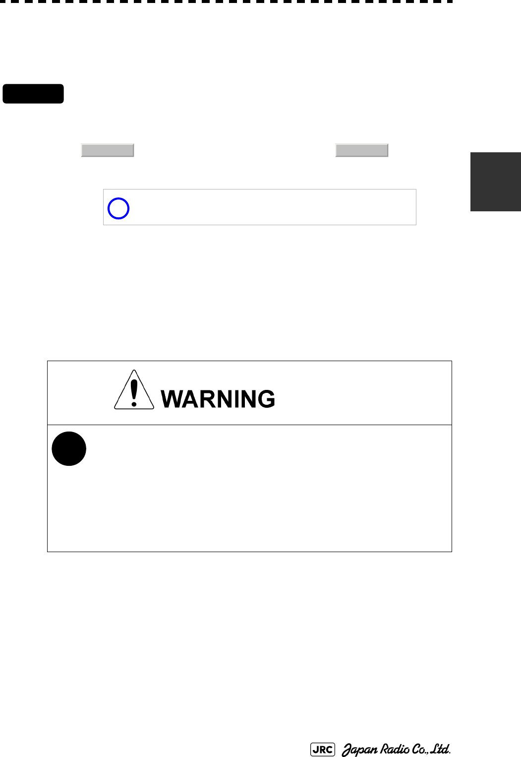
JMA-9100 Instruction Manual > 3.BASIC OPERATION > 3.1 OPERATION FLOW
3-5
3
3.1.5 End the Operation and Stop the System
Exit
1) Press [TX/STBY] key.
The radar will stop transmission and the antenna will stop rotating.
at the upper left of the radar display changes to .
2) Press [POWER] key.
The system will be turned off.
Maintain the standby state if radar observation is restarted in a
relatively short time.Only pressing the [TX/STBY] key starts
observation.
!
• When conducting maintenance work, make sure to turn
off the power and make the main breaker OFF so that the
power supply to the equipment is completely cut off.
• Some equipment components can carry electrical
current even after the power switch is turned off, and
conducting maintenance work without unplugging the
power connector may result in electrocution, equipment
failure, or accidents.
Transmit Standby
i

3-6
JMA-9100 Instruction Manual > 3.BASIC OPERATION > 3.2 OBSERVE AND ADJUST VIDEO
3.2 OBSERVE AND ADJUST VIDEO
3.2.1 Adjust Monitor Brilliance [BRILL]
Procedures
1) Obtain the best-to-see display with optimum brilliance by turning
the [BRILL] dial at the lower right of the monitor unit.
Turning the [BRILL] dial clockwise increases the brilliance of the entire display.
Conversely, turning the [BRILL] dial counterclockwise decreases the brilliance of the entire
display.
In consideration of the ambient brightness, adjust display brilliance that is high enough to
easily observe the radar display but does not glare.
3.2.2 Change Observation Range [RANGE+/-]
Procedures
1) Pressing the [RANGE+] key will increase the observation range,
enabling the wider area to be observed.
Increasing the observation range will enable a wider range to be observed.
However, a video image is small and the ability to detect targets near own ship decreases.
Therefore, when observing the vicinity of own ship, use the smaller observation range.
2) Pressing the [RANGE-] key will decrease the observation range,
reducing the area that can be observed.
Decreasing the observation range will enable the vicinity of own ship to be enlarged.
However, caution must be taken because video images of the area beyond the observation
range cannot be displayed.
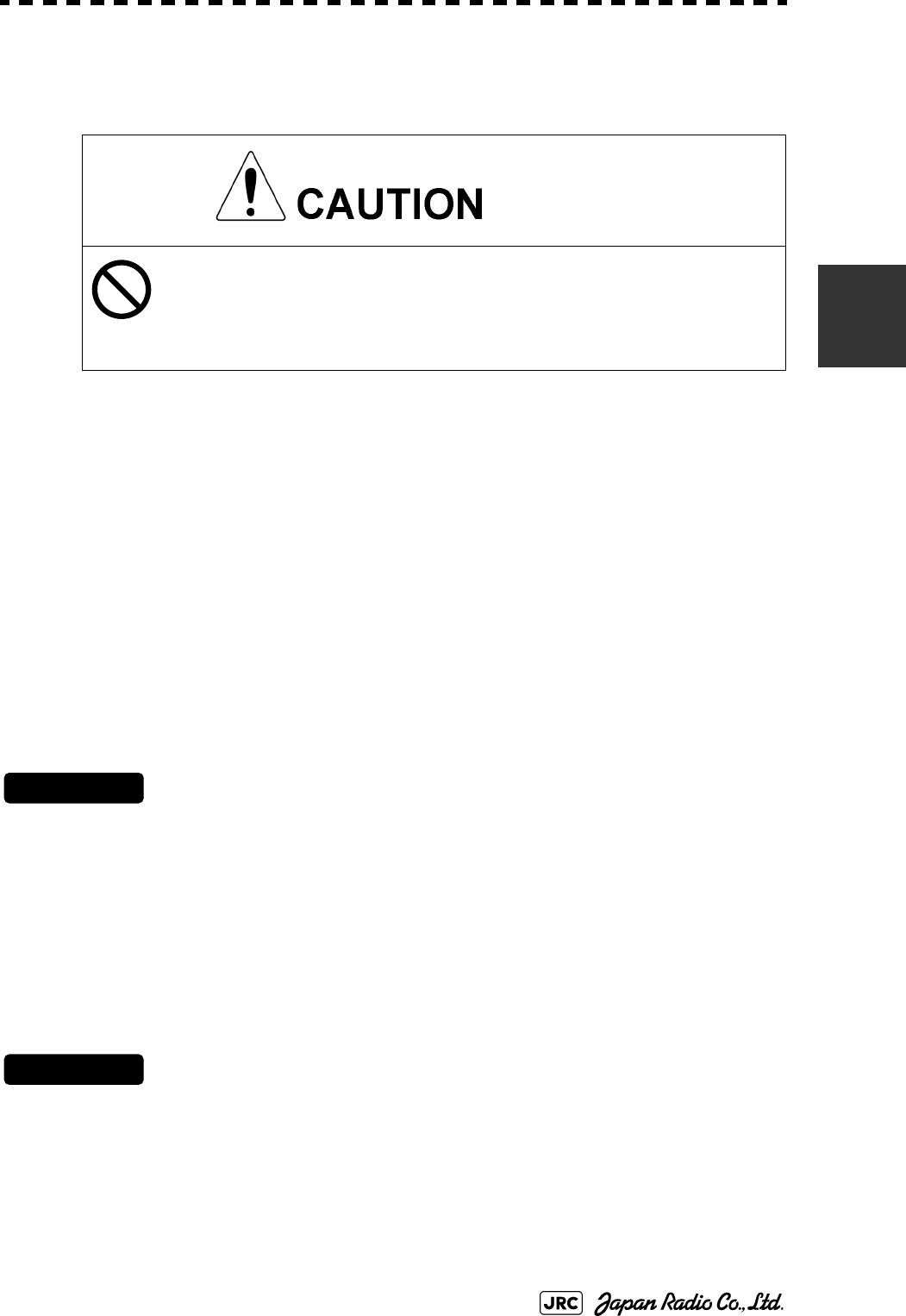
JMA-9100 Instruction Manual > 3.BASIC OPERATION > 3.2 OBSERVE AND ADJUST VIDEO
3-7
3
3.2.3 Tune
This radar system provides the automatic tune mode and the manual tune mode.
The automatic tune mode automatically adjusts the tuning of the transmitting
frequency and the receiving frequency, and the manual tune mode enables tuning
to be adjusted by using the dial located on the operation panel. Normally use the
automatic tune mode. Only when the best tuning is not possible by the automatic
tune mode due to the deterioration of magnetron, use the manual tune mode.
The currently used tune mode is displayed in the area at the lower left of the
display.
3.2.3.1 When using the automatic tune mode
Procedures
1) Press the [TUNE] dial to set the automatic tune mode.
Tune adjustment is automatically conducted in the automatic tune mode. Tune is adjusted at
the start of transmission, at the change of the range or pulse width. Tune adjustment is
completed within several seconds.
3.2.3.2 When using the manual tune mode
Procedures
1) Press the [TUNE] dial to set the manual tune mode.
2) Turn the [TUNE] dial to make adjustments so that the tuning bar
is maximized. The tuning bar is displayed in the area at the upper
left of the display.
Normally, use the automatic tune mode.
Use the manual tune mode only when best tuning is
not possible in the automatic tune mode due to
deterioration of magnetron.
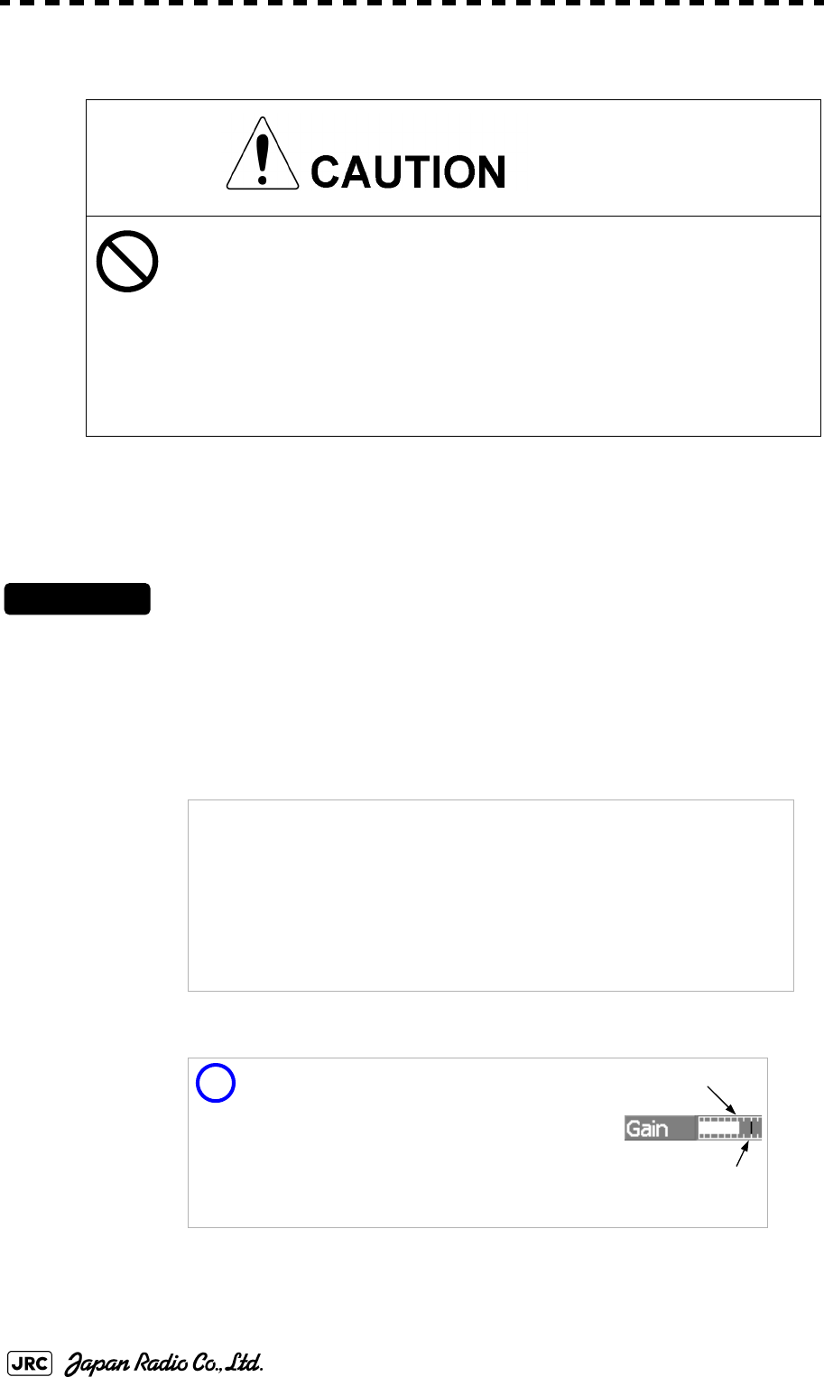
3-8
JMA-9100 Instruction Manual > 3.BASIC OPERATION > 3.2 OBSERVE AND ADJUST VIDEO
3.2.4 Adjust Gain [GAIN]
See also the Section 3.2.8 "To get the appropriate image that targets can be easily
observed".
Procedures
1) Adjust noise on the radar display by turning the [GAIN] dial until
targets can be easily observed.
Turning [GAIN] dial clockwise increases gain.
Turning [GAIN] dial counterclockwise decreases gain.
If the gain is too high, unnecessary signals including
receiver noise and false images increase resulting in
reduction of visibility of targets.
On the contrary, if the gain is too low, targets including
ships and dangerous objects may not be clearly
indicated.
Be sure to always adjust for the best gain.
Turning the [GAIN] dial clockwise will increase the receiving gain, and the
range to observe radar video is widened. However, if the gain is too high,
unnecessary signals including receiver noise and false images increase
resulting in reduction of targets' visibility.
To observe densely crowded targets or short-range targets, turning the
[GAIN] dial counterclockwise will decrease the receiving gain, which
enables targets to be easily observed. However, caution must be taken so
as not to overlook a small and important target.
i
It is recommended to restore the setting to
the factory default, if you lost the appropriate
settings.The factory default level is shown on
the bar chart as a green line.
The factory defafult level is assigned by
every function mode. See the Section 3.9
"USE FUNCTION KEY [USER]"
Current Level
Factory Default
JMA-9100 Instruction Manual > 3.BASIC OPERATION > 3.2 OBSERVE AND ADJUST VIDEO
3-9
3
3.2.5 Suppress Sea Clutter [SEA]
See also the Section 3.2.8 "To get the appropriate image that targets can be easily
observed".
3.2.5.1 Using the manual sea clutter suppression mode
Procedures
1) Adjust the sea clutter returns on the radar display by turning the
[SEA] dial until targets can be easily observed.
Turning [SEA] dial clockwise suppresses sea clutter returns.
Turning [SEA] dial counterclockwise intensifies sea clutter returns.
When using the [AUTO SEA] function, never set the
suppression level too high canceling out all image
noises from the sea surface at close range.
Detection of not only echoes from waves but also
targets such as other ships or dangerous objects will
become inhibited.
When using the [AUTO SEA] function, make sure to
choose the most appropriate image noise suppression
level.
The sea clutter suppression function suppresses sea clutter returns by
decreasing the receiving gain on a short range.
Turning the [SEA] dial clockwise heightens the effect of sea clutter
suppression. However, be careful that excessive suppression causes
low signal-strength targets such as buoys and boats to disappear from
the radar display.

3-10
JMA-9100 Instruction Manual > 3.BASIC OPERATION > 3.2 OBSERVE AND ADJUST VIDEO
3.2.5.2 Using the automatic sea clutter suppression mode
The sea clutter suppression in accordance with the intensity of sea clutter is
possible. Use this mode when the sea clutter's intensity differs according to
directional orientation.
Procedures
1) Press the [SEA] dial. Alternatively, Left-click the Sea MAN
button located at the lower left of the display.
The automatic sea clutter suppression mode is selected, and Sea AUTO is displayed in the
lower left of the radar display.
2) Make adjustments by turning the [SEA] dial.
Even when the automatic sea clutter suppression mode is selected, turning the [SEA] dial can
make fine adjustments manually.
Cancel
1) ress the [SEA] dial. Alternatively, Left-click the Sea AUTO
button located at the lower left of the display.
The automatic sea clutter suppression mode is cancelled, and Sea MAN is displayed in the
lower left of the radar display.
i
It is recommended to restore the setting to
the factory default, if you lost the appropriate
settings.The factory default level is shown on
the bar chart as a green line.
The factory defafult level is assigned by
every function mode. See the Section 3.9
"USE FUNCTION KEY [USER]"
NOTE:
When the automatic sea clutter suppression mode is selected,
the automatic rain/snow suppression mode is switched to the
manual mode.
To select both the sea clutter suppression function and the rain/
snow suppression function in the automatic mode, use the
automatic rain/snow suppression mode.
Current Level
Factory Default
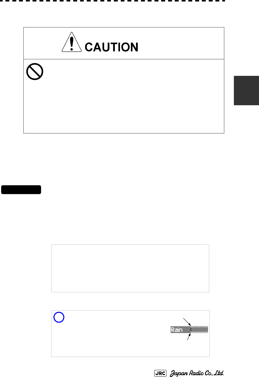
JMA-9100 Instruction Manual > 3.BASIC OPERATION > 3.2 OBSERVE AND ADJUST VIDEO
3-11
3
3.2.6 Suppress Rain/Snow Clutter [RAIN]
See also the Section 3.2.8 "To get the appropriate image that targets can be easily
observed".
3.2.6.1 Using the manual rain / snow clutter suppression mode
Procedures
1) Adjust the rain / snow clutter returns of the display by turning the
[AUTO-RAIN] dial until targets can be easily observed.
Turning [RAIN] dial clockwise suppresses rain / snow clutter returns.
Turning [RAIN] dial counterclockwise intensifies rain / snow clutter returns.
When using the [AUTO RAIN] function, never set the
suppression level too high canceling out all image
noises from the rain or snow at the close range.
Detection of not only echoes from the rain or snow but
also targets such as other ships or dangerous objects
will become inhibited.
When using the [AUTO RAIN] function, make sure to
choose the most appropriate image noise suppression
level.
When the [RAIN] dial is turned clockwise, the rain / snow clutter
suppression function suppresses rain / snow clutter returns and gets
targets hidden by rain / snow clutter returns to appear of the display.
However, be careful that excessive suppression may cause small
targets to be overlooked. Since the rain / snow clutter suppression
function also has the effect of suppressing sea clutter, the suppression
efficiency improves when the [RAIN] dial is used with the [SEA] dial. In
general, turn the [RAIN] dial fully to the left.
i
It is recommended to restore the setting to
the factory default, if you lost the appropriate
settings.The factory default level is shown on
the bar chart as a green line.
The factory defafult level is assigned by
every function mode. See the Section 3.9
"USE FUNCTION KEY [USER]"
Current Level
Factory Default

3-12
JMA-9100 Instruction Manual > 3.BASIC OPERATION > 3.2 OBSERVE AND ADJUST VIDEO
3.2.6.2 Using the automatic rain / snow clutter suppression mode
The rain / snow clutter suppression in accordance with the intensity of rain / snow
clutter is possible. Use this mode when the rain / snow clutter's intensity differs
according to directional orientation.
Procedures
1) Press the [RAIN] dial. Alternatively, Left-click the Rain MAN
button located at the lower left of the display.
The automatic rain / snow clutter suppression mode is selected, and Sea AUTO, Rain
AUTO is displayed in the lower left of the radar display.
2) Make adjustments by turning the [RAIN] dial and the [SEA] dial.
Even when the automatic rain / snow clutter suppression mode is selected, turning the
[RAIN] dial and the [SEA] dial can make fine adjustments manually.
Cancel
1) Press the [RAIN] dial. Alternatively, Left-click the Rain AUTO
button located at the lower left of the display.
The automatic rain / snow clutter suppression mode is cancelled, and Sea AUTO, Rain
AUTO is changed to Sea MAN ,Rain MAN in the lower left of the radar display.
3.2.7 Reset Alarm Buzzer [ALARM ACK]
When an audible alarm is issued, use ALARM ACK to acknowledge the alarm
information, stop the alarm buzzing, and stop the alarm lamp flashing. (If more
than one alarm has occurred, press the switch for each alarm indication.) The
alarm stops buzzing, but the alarm indication does not disappear.
Procedures
1) Press [ALARM ACK] key. Alternatively, Left-click the Alarm
Acknowridge button located at the lower right of the display.
The alarm will stop buzzing.
NOTE:
When the automatic rain / snow clutter suppression mode is
selected, the automatic sea clutter suppression mode is also
activated.
It is not possible to set only the rain / snow clutter suppression
function to the automatic mode.
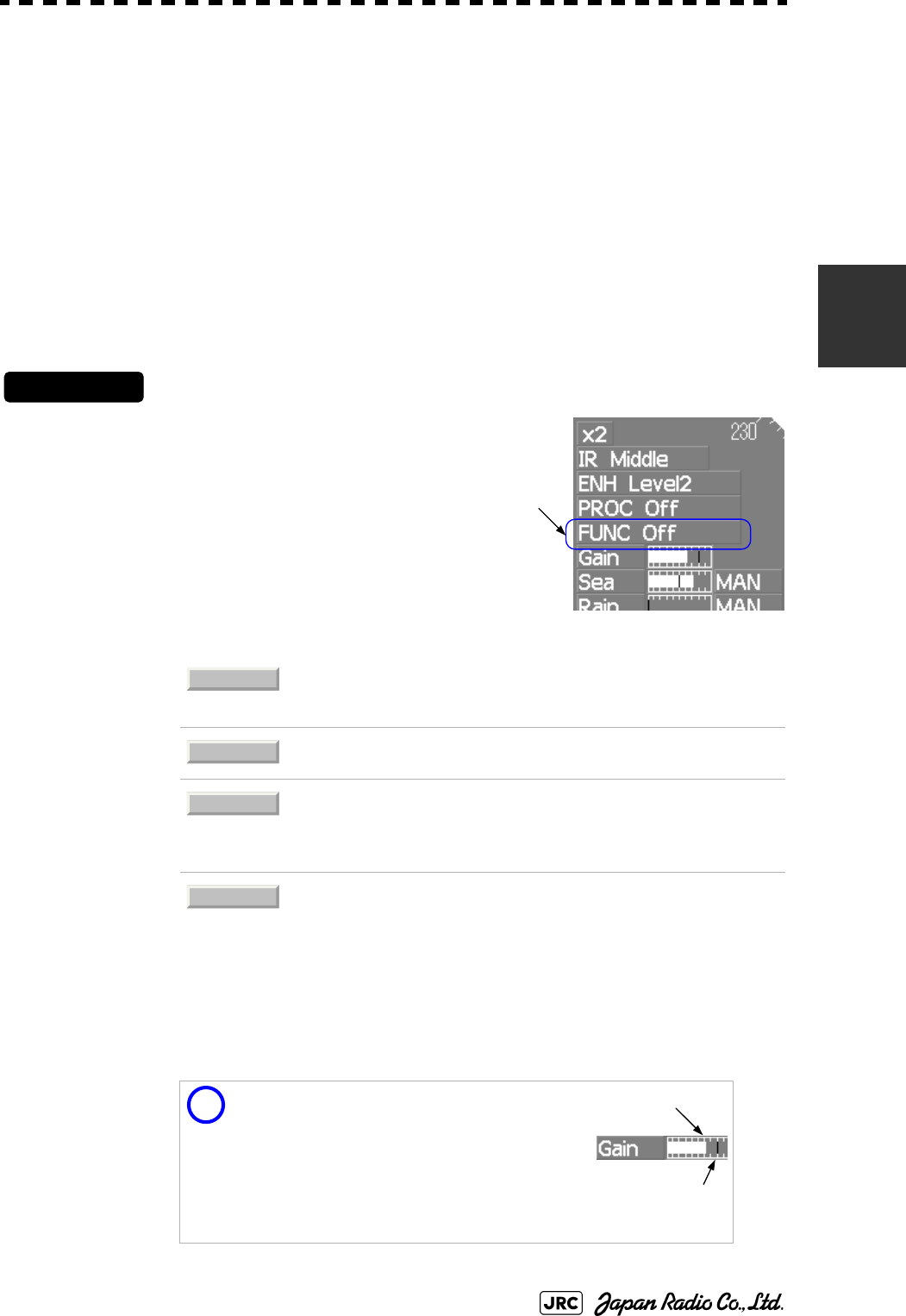
JMA-9100 Instruction Manual > 3.BASIC OPERATION > 3.2 OBSERVE AND ADJUST VIDEO
3-13
3
3.2.8 To get the appropriate image that targets can be easily
observed
To get the appropriate image that targets can be easily observed which requires an
understanding for RADAR signal processing features and an adjustment for the
sea state. All of the parameter can be set indivisually and manually, but it may by
difficult for even expert person.
The sets of signal processing parameters for the general using condition are stored
in FUNC as factory default settings. In most cases, to select the FUNC mode
which fit in the current sea state is lead to get the appropriate image easily and
quickly. So It is recommended to enable the FUNC mode.
Procedures
1) Press [USER] key / Press
FUNC mode switch button
and select the mode which fit
in the current sea state.
The four preset modes is assigned on the
FUNC mode. For details, refer to the
Section 3.9 "USE FUNCTION KEY
[USER]".
2) Make adjustments by turning the [GAIN] dial, the [SEA] dial and
the [RAIN] dial when it is necessary.
In most cases, it may be get the appropriate image.
: Use this mode to monitor a relatively short range, for example,
bays and coasts where many boats and ships are
running.(Importance is attached to resolution.)
: Use this mode to monitor a relatively long range, for example,
the open sea. (Importance is attached to long-range gain.)
: Use this mode when many rain / snow clutter returns or sea
clutter returns are detected in stormy weather. (Importance is
attached to rain / snow clutter and sea clutter suppression, and
gain slightly lowers.)
: Use this mode when sea clutter is not strong but rain / snow
clutter is strong. (Importance is attached to rain / snow clutter
suppression, and gain slightly lowers.)
i
It is recommended to restore the setting to
the factory default, if you lost the appropriate
settings.The factory default level is shown on
the bar chart as a green line.
The factory defafult level is assigned for
every function mode. See the Section 3.9
"USE FUNCTION KEY [USER]"
Function
(FUNC) mode
Coast
Deep Sea
Storm
Rain
Current Level
Factory Default
3-14
JMA-9100 Instruction Manual > 3.BASIC OPERATION > 3.3 OPERATION PROCEDURES
3.3 OPERATION PROCEDURES
3.3.1 Move Cross Cursor Mark by Trackball
The cross cursor mark + is used for position designation and other purposes in
various operating procedures. The cross cursor mark + moves in coupling with
the trackball. If the trackball is rotated up and down or right and left, the cross
cursor mark follows the move of the trackball.
Operators must be familiar with trackball operation before running the system.
3.3.1.1 Operation inside Radar Video PPI
The cross cursor mark as shown at right is displayed inside the radar video
PPI.
•The distance, bearing, and latitude/longitude are digitally indicated in the
cursor bearing, distance, latitude, and longitude fields (located at the upper
right of the radar display.)
•When moving the current center position, use the cross cursor mark to
designate a new center position.
•Use the cross cursor mark to create marks and lines.
•Use the cross cursor mark to manually acquire a target in the target tracking /
AIS display functions.
3.3.1.2 Operation outside Radar Video PPI
As shown at right, the cursor mark changes into the cursor outside the radar
video PPI.
•Use the cursor to operate software buttons.
•Use the cursor to select menu items.
i
The EBL / VRM dial is available for operating the cursor mark.
Pressing the EBL dial for 2 seconds can perform switching to
the trackball operation. For details, refer to Section 3.8.4 "Set
Cursor (Cursor Setting)".
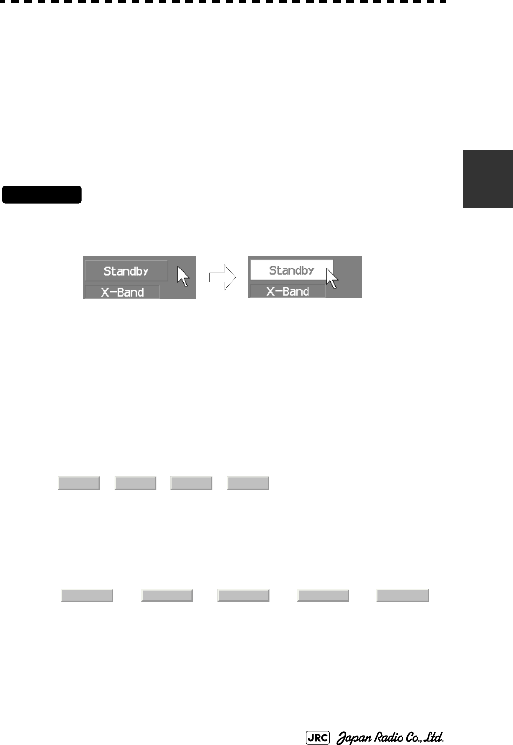
JMA-9100 Instruction Manual > 3.BASIC OPERATION > 3.3 OPERATION PROCEDURES
3-15
3
3.3.2 Operate Software Buttons
Software buttons are provided on the radar display so as to easily switch functions
without operating menu items.
For software buttons that can be operated and their locations, see Section 2.3
"FUNCTIONS OF SOFTWARE BUTTONS".
Procedures
1) Put the pointer on the software button on the radar display.
The software button indicated by the cursor will be shown in reverse video, which indicates
that the button is specified.
2) Press the left button of the trackball.
The operating state changes according to the function of the software button.
In this instruction manual, this manual operation is described as "left-clicking."
•On/Off settings
Each time the left button is pressed, the operating state switches as follows:
→→→
•Multiple settings
For example, each time the left button is pressed, the operating state switches as
follows:
→ → → →
On Off On Off
IR Off IR Low IR Meddle IR High IR Off

3-16
JMA-9100 Instruction Manual > 3.BASIC OPERATION > 3.3 OPERATION PROCEDURES
3.3.3 Basic Menu Operation
3.3.3.1 To open the menu
By left-clicking the button located at the lower right of the radar
display, the main menu will open
By left-clicking the buttons, , , and , adjacent to
, each function's exclusive menu will open.
For the arrangement of software buttons, see Section 2.3 "FUNCTIONS OF
SOFTWARE BUTTONS".
3.3.3.2 To close the menu
By left-clicking the button, the menu will close and the target data
display screen will appear.
Alternatively, left-click located at the bottom of the menu until the
menu will close.
3.3.3.3 To move to a lower level of the menu
The menu is in hierarchical structure. By left-clicking the software button for a
desired menu item, it is possible to move to the lower level of the menu.
Alternatively, Click items corresponding to the desired menu item number, and the
mark will appear at the right end of a menu item having a lower level.
3.3.3.4 To move to a higher level of the menu
By left-clicking at the bottom of the menu while the menu is open, it is
possible to return to the upper level of the menu.
3.3.3.5 To determine an item
By left-clicking the software button for a menu item for which settings are to be
changed, the selected item will be displayed.
3.3.3.6 To determine the selected item
Left-click the software button for an item you want to set, and then the selected
item will be determined.
If you do not change the setting, right-click the button. The selected item will
close without changing the setting.
Main
TT AIS AZ
Main
Target
0.Exit
>
0.Exit
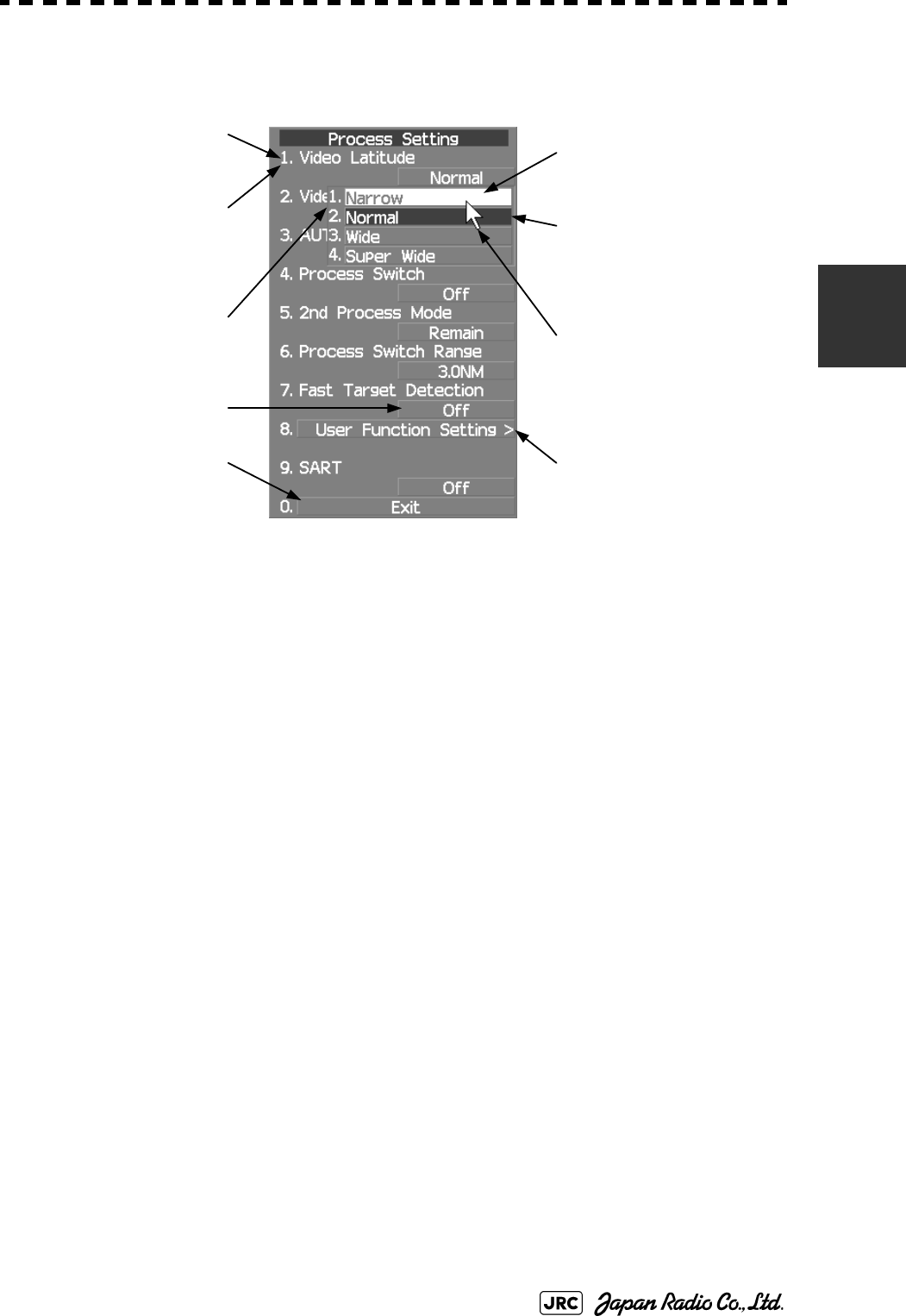
JMA-9100 Instruction Manual > 3.BASIC OPERATION > 3.3 OPERATION PROCEDURES
3-17
3
3.3.3.7 Menu Operation with the Trackball
3.3.4 Operation on Numeric Value, Latitude / Longitude and
Character Input menu
When a numeric value must be entered while operating this radar system, the
numeric value input screen will appear. In that case, enter a numeric value
according to the following operation method.
Press numeric keys
corresponding to the desired
item number to display the
selected item.
Press numeric keys
corresponding to the
desired item number to
select a set value.
Software button
Press the
[0]
key to
move to the higher level.
When the [ > ] mark appears
at the right end of a menu
item, press numeric keys
corresponding to the selected
item number to move to a
lower level.
Item
Selected item
Cursor
Present state
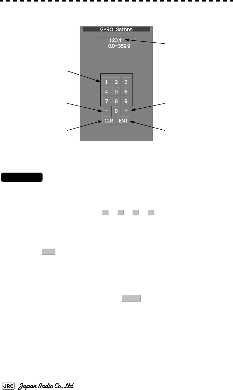
3-18
JMA-9100 Instruction Manual > 3.BASIC OPERATION > 3.3 OPERATION PROCEDURES
3.3.4.1 Numeric value input screen
3.3.4.2 Directly entering a numeric value
Procedures
1) On the numeric value input screen, sequentially left-click the
software number keys located on the radar screen, and enter a
desired numeric value.
For example, when entering → → → for a bearing value, sequentially left-
click the software number keys as shown below.
2) Make sure that the entered value is correct, and left-click the
button.
The set value is reflected to the operating state.
3) To stop entering a value, right-click the [ENT] button.
Alternatively, left-click the button.
The numeric value input screen will close without reflecting the set value to the operating
state.
Entered value
+ button
Enter buttonClear button
- button
Numeric button
1
234
ENT
CLR
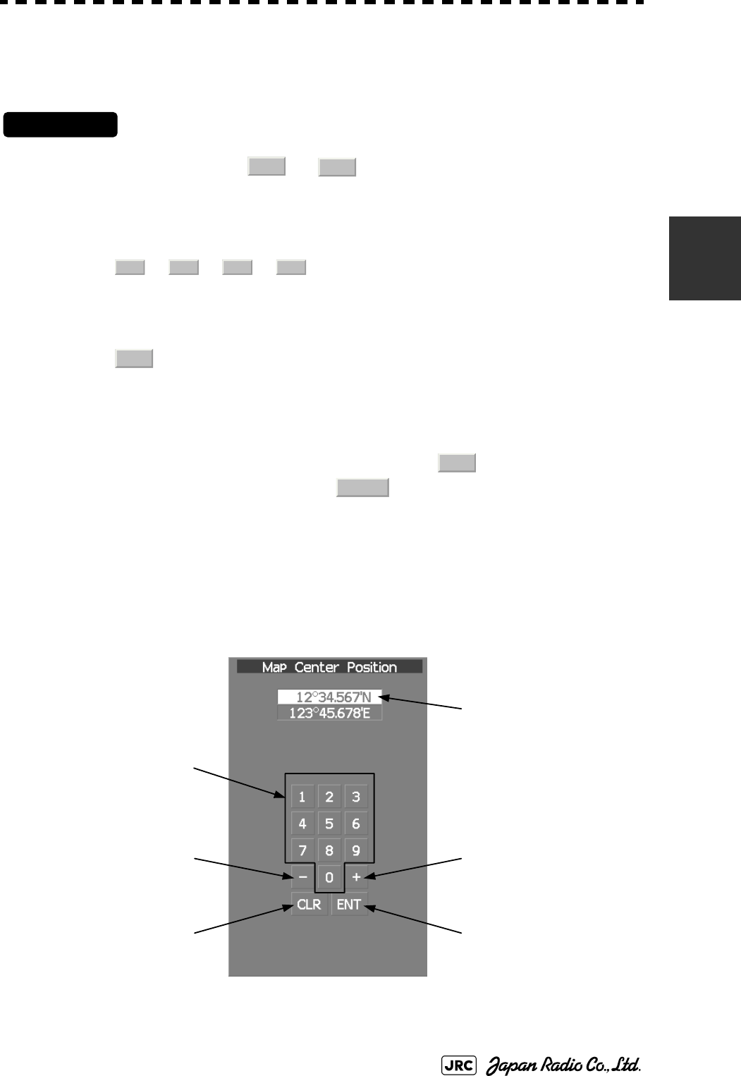
JMA-9100 Instruction Manual > 3.BASIC OPERATION > 3.3 OPERATION PROCEDURES
3-19
3
3.3.4.3 Increasing or decreasing a numeric value
Procedures
1) On the numeric value input screen, sequentially left-click the
software button or located on the radar screen, and
enter a desired numeric value.
For example, when adjusting 123.0° to 123.4° for a bearing value, sequentially left-click the
software number keys as shown below.
→ → →
2) Make sure that the entered value is correct, and left-click the
button.
The set value is reflected to the operating state.
3) To stop entering a value, right-click the button.
Alternatively, left-click the button.
The numeric value input screen will close without reflecting the set value to the operating
state.
3.3.4.4 Latitude/longitude input screen
+-
++++
ENT
ENT
CLR
Entered latitude /
longitude
+ button (north latitude /
east longitude )
ENT buttonCLR button
- button (south latitude /
west longitude)
Numeric button

3-20
JMA-9100 Instruction Manual > 3.BASIC OPERATION > 3.3 OPERATION PROCEDURES
3.3.4.5 Entering latitude/longitude
Procedures
1) On the latitude/longitude input screen, sequentially click numeric
buttons to enter latitude (XX°XX.XXX').
For example, to enter 12°34.567', sequentially click numeric buttons as follows.
→ → → → → →
2) To make change between north latitude and south latitude, use
and .
North latitude:Left-click the button.
South latitude:Left-click the button.
3) Left-click the button.
The manually entered latitude value is determined. Then, enter the longitude value.
4) Sequentially click numeric buttons to enter longitude (XXX°XX.
XXX').
5) To make change between east longitude and west longitude, use
and .
East longitude: Left-click the button.
West longitude: Left-click the button.
6) Left-click the button.
The manually entered longitude value is determined.
7) To cancel input, put the cursor on and then left-click the
button.
The latitude/longitude input screen will close without reflecting the set value to the operating
state.
1234567
+-
+
-
ENT
+-
+
-
ENT
CLR
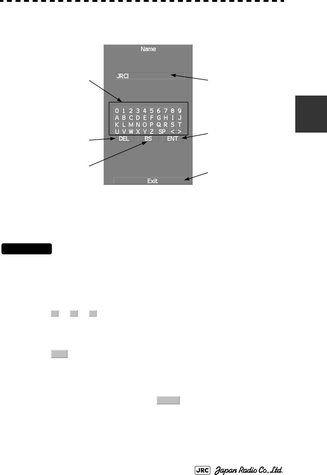
JMA-9100 Instruction Manual > 3.BASIC OPERATION > 3.3 OPERATION PROCEDURES
3-21
3
3.3.4.6 Character input screen
3.3.4.7 Entering a character
Procedures
1) On the character input screen, use trackball to select alphabet
from A to Z, numbers from 0 to 9, or symbols (only comments for
mark/line), and then left-click the ENT button to enter one
character of the name to be inputted.
For example, JRC for a name, click button as follows:
→ →
2) Make sure that the entered character is correct, left-click the
button.
The character has been entered.
3) To cancel input, left-click the button.
The character input screen will be closed without entering the character.
Enter button
Back Space button
Delete button
Character/Number button Entered character
Exit button
J
R
C
ENT
Exit

3-22
JMA-9100 Instruction Manual > 3.BASIC OPERATION > 3.3 OPERATION PROCEDURES
3.3.5 Overview of Menu Structure
The menu structure of this radar system consists of eight frequently used function
menus, one main menu, and one service man menu used for the installation
settings.
Software buttons for opening those menus are displayed in the menu area located
at the bottom ten of the display.
For each menu item and structure, see the menu list in the appendix.
To prevent incorrect use, enter the special code to open the service man menu. For
operating the service man menu, see Section 7.1.1 "How to Open the Serviceman
Menu(Service Man Menu)"
Frequently used functions
Main menu
Serviceman menu
TT Used for operating and setting the target tracking function.
Track Used for operating and setting the other ship trails function.
AIS Used for operating and setting the AIS display function.
Route Used for operating and setting the route function.
PI Used for operating and setting the parallel-index-line function.
AZ Used for operating and setting the automatic acquisition /
activate function.
U.MAP Used for operating and setting the user map function.
Main Used for operating and setting the functions.
This menu is used for operation and settings when a system is
installed.
It is not used during normal operation.The special code must be
entered to open the service man menu.
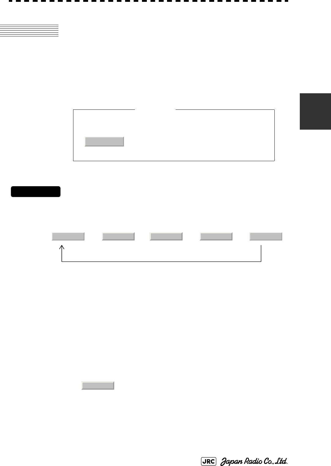
JMA-9100 Instruction Manual > 3.BASIC OPERATION > 3.4 GENERAL RADAR OPERATION
3-23
3
3.4 GENERAL RADAR OPERATION
3.4.1 Interference Rejection (IR)
Interference by other radars is rejected.
Procedures
1) Left-click the IR button located at the lower left of the radar
display.
The interference rejection modes are switched.
→ → → →
When a high interference rejection level is selected, the radar’s ability of
detecting small targets such as buoys and small boats lowers.
In general, should be selected.
• When viewing a radar beacon or SART signal, select
(Interference Rejector OFF) because IR
processing suppresses the video.
Rejection levels of the interference rejector
IR Off : Interference rejector off
IR Low : Interference rejection level - low
IR Middle : Interference rejection level - moderate
IR High : Interference rejection level - high
Attention
IR Off
IR Off IR Low IR Meddle IR High IR Off
IR Low
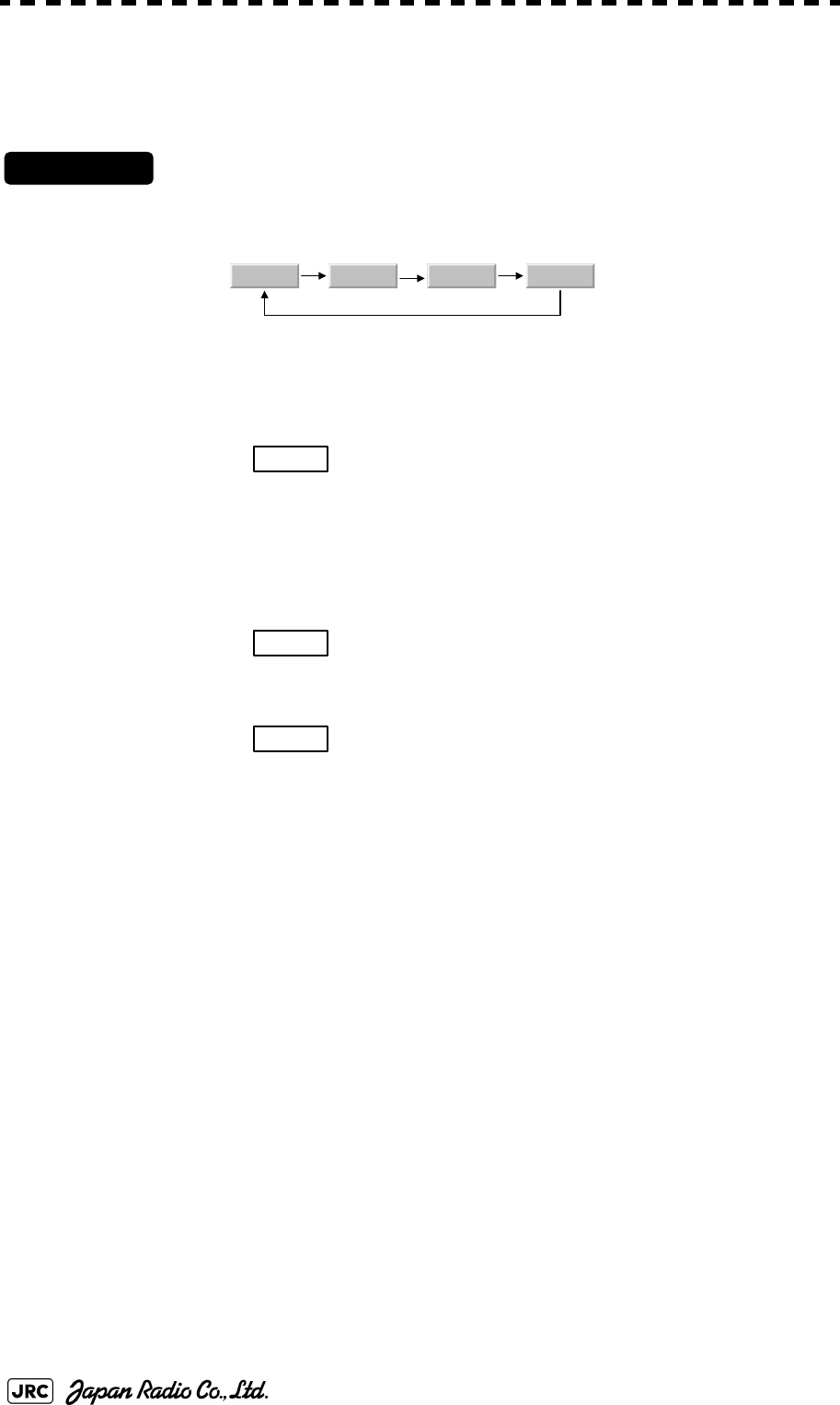
3-24
JMA-9100 Instruction Manual > 3.BASIC OPERATION > 3.4 GENERAL RADAR OPERATION
3.4.2 Switch Transmitter Pulse Length [GAIN]
Procedures
1) Press [GAIN] dial
Values of the transmitter pulse width are switched.
Usable transmitter pulse width differs according to the type of antenna being used
and the observation range being used. For usable pulse width, see Section 11.8
"SCANNER UNIT (NKE-1139)" ~Section 11.14 "SCANNER UNIT (NKE-
2103-6HS)".
Effects of transmitter pulse width
With selected: The transmitter pulse becomes shorter, and the
range resolution improves. The effect of
suppressing sea clutter returns and rain/snow
clutter returns heightens.
Recommended condition for selection: In bays/harbors where targets are densely
crowded. Rough sea state due to torrential rain or
stormy weather.
With selected: The normal transmitter pulse length is set. Both
range resolution and gain are appropriately set.
Recommended condition for selection: General navigation
With selected: The transmitter pulse becomes longer, and gain
improves. Small targets are zoomed and are easy
to observe. When the sea state is bad, detection
performance decreases.
Recommended condition for selection: Detection of small targets in good weather
conditions.
MP1 MP2 LP1 LP2
SP
MP
LP

JMA-9100 Instruction Manual > 3.BASIC OPERATION > 3.4 GENERAL RADAR OPERATION
3-25
3
3.4.3 Target Enhance (ENH)
The dimension of video display is enlarged to enhance a target.
Procedures
1) Left-click the ENH button located at the lower left of the radar
display.
The target enlargement levels are switched.
⇒ ⇒ ⇒ ⇒
In general, ENH Level1 or ENH Level2 should be selected.
Effect of target enlargement
:Expansion off Select this mode particularly when
resolution is required.
:Expansion small Select this mode in general. Radar echoes
are expanded by 1 scale in all directions.
:Expansion medium Select this mode to easily view the radar
video. Radar echoes are expanded by 2
scales in all directions on the display.
Expansion large Select this mode to detect small targets
such as buoys. The expansion near a
screen center is added to ENH Level2.
NOTE:
When ENH Level3 is selected, sea clutter returns and rain/
snow clutter returns are apt to be expanded. When using this
expansion mode, operate [SEA] dial and [RAIN] dial to
suppress sea clutter returns and rain/snow clutter returns.
ENH Off ENH Level1 ENH Level2 ENH Level3 ENH Off
ENH Off
ENH Level1
ENH Level2
ENH Level3

3-26
JMA-9100 Instruction Manual > 3.BASIC OPERATION > 3.4 GENERAL RADAR OPERATION
3.4.4 Use Video Processing (PROC)
This function reduces unnecessary noise to highlight targets.
Procedures
1) Left-click the PROC button located at the lower left of the
display.
The video processing modes are switched.
→ →
← ←
• When viewing a radar beacon, SART signal, or fast
moving target on the radar display, select
(video process off).
• If video processing mode is set to CORREL , it may
be difficult to detect high speed target.
Video process modes
: Select this mode in general.
: Select this mode when many rain/snow clutter returns are detected.
: Select this mode to highlight targets while suppressing sea clutter
returns.
: Select this mode to detect small targets hidden by sea clutter
returns.
: Select this mode when own ship yaws wildly.
: Select this mode to detect small targets of which detection
probability is low.
Attention
PROC Off
PROC Off 3Scan CORREL 4Scan CORREL
Peak Hold Remain 5Scan CORREL
PROC Off
3Scan CORREL
4Scan CORREL
5Scan CORREL
Remain
Peak Hold

JMA-9100 Instruction Manual > 3.BASIC OPERATION > 3.4 GENERAL RADAR OPERATION
3-27
3
3.4.5 Switch Azimuth Display Mode (AZI MODE)
Select the bearing for the radar video to be displayed on the radar display.
Procedures
1) Left-click the AZI Mode button located at the lower left of the
display.
The bearing display modes are switched.
→ →
True Bearing Mode [North Up]
The video is displayed so that the zenith of the PPI (0° on range rings) points to the due
north. Fixed targets do not flicker and are easily identified on the chart, and the true bearing
of a target can easily be read out.
Relative Bearing Mode [Head Up]
The video is displayed so that the ship’s heading line points to the zenith of the PPI (0° on
range rings). Since targets are displayed in their directions relative to the ship’s heading
line, the operator can view the video in the same field of view as in operating the ship at sea.
This mode is suitable for watching over other ships.
Course-up Bearing Mode [Course Up]
By setting the course-up mode, own ship's course is fixed so that it is located on the zenith of
the radar display (0° on range rings). In the same way as in the North-up mode, fixed targets
do not flicker, and are stabilized even if the ship is yawing. The bearing of the heading line
varies by the same shift of own ship’s course. To change the course, press the [AZI
MODE] key several times again to select the course-up mode so as to set a new course.
H Up N Up C Up
HL
North-up mode Head-up mode Course-up mode
HLNorth HL
North
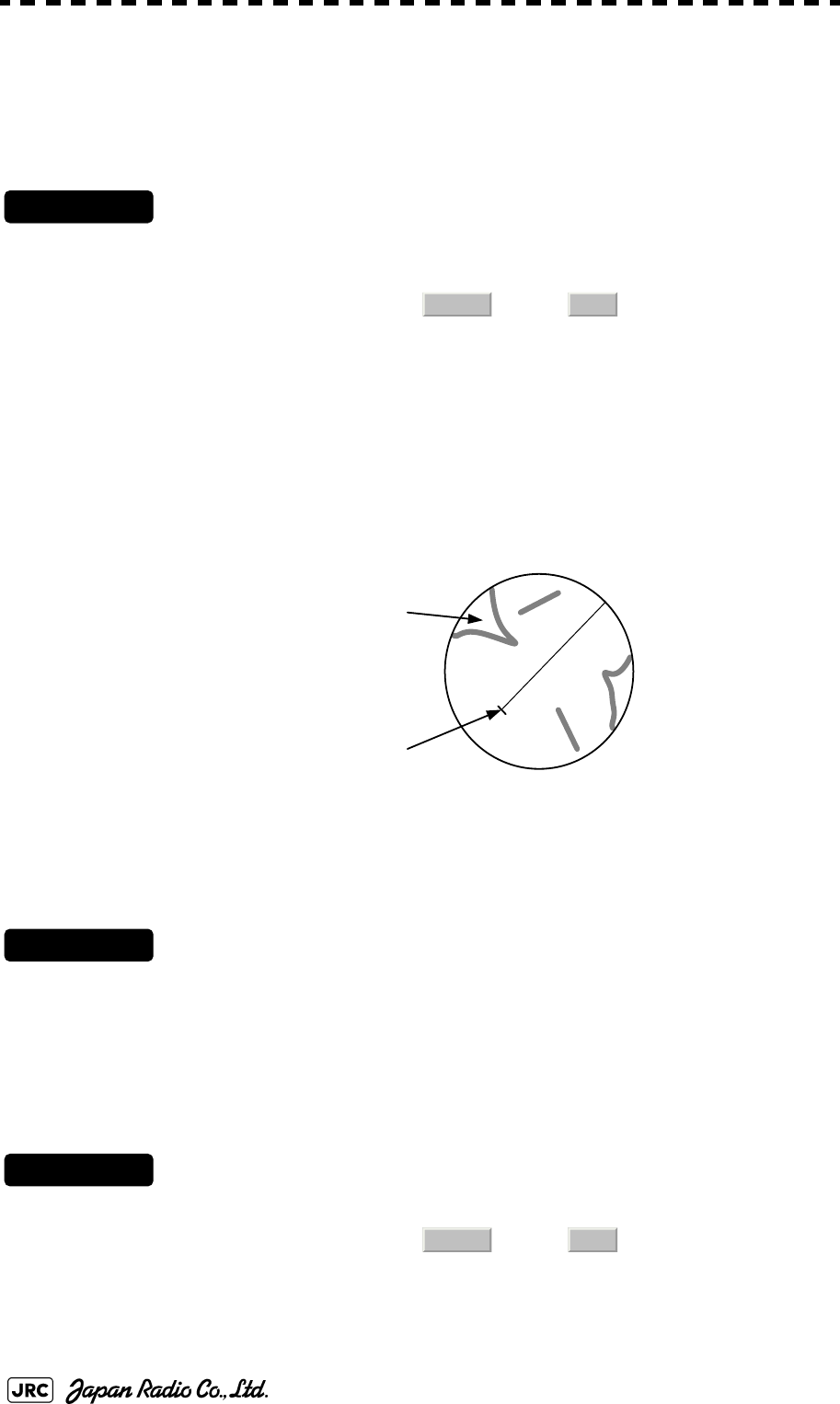
3-28
JMA-9100 Instruction Manual > 3.BASIC OPERATION > 3.4 GENERAL RADAR OPERATION
3.4.6 Switch True/Relative Motion Display Mode (TM/RM)
3.4.6.1 Switching Relative Motion (RM) Mode to True Motion (TM) Mode
Procedures
1) Left-click the motion mode button located at the upper left of the
radar display.
→
The true motion mode will be selected. In the true motion mode, the own ship’s position on
the radar display moves depending upon its speed and course and the influence of the
current. Land and other fixed targets are fixed on the radar display and only actually moving
targets move on the radar display. When the true motion mode is selected, the own ship’s
position is set to about 60% of the display radius in the opposite direction to its course
allowing for the influence of the current. Own ship starts moving depending upon its speed
and course and the influence of the current. Subsequently, when own ship arrives at the
position of about 66% of the display radius, it is automatically reset to its initial position at
about 60% of the display radius in the opposite direction to its course allowing for the
influence of the current.
3.4.6.2 Resetting Own Ship to its Initial Position in True Motion (TM) Mode
Procedures
1) Left-click the motion mode button for 2 seconds.
Own ship will be reset to its initial position as established when the relative motion mode is
changed to the true motion mode. The ship starts moving from that position.
3.4.6.3 Switching True Motion (TM) Mode to Relative Motion (RM) Mode
Procedures
1) Left-click the motion mode button.
→
The relative motion mode will be selected. Own ship returns to the center of the radar
display.
RM(T) TM
HL
True Motion Display
Fixed on the radar display
Moving depending on
own ship’s speed
RM(T) TM
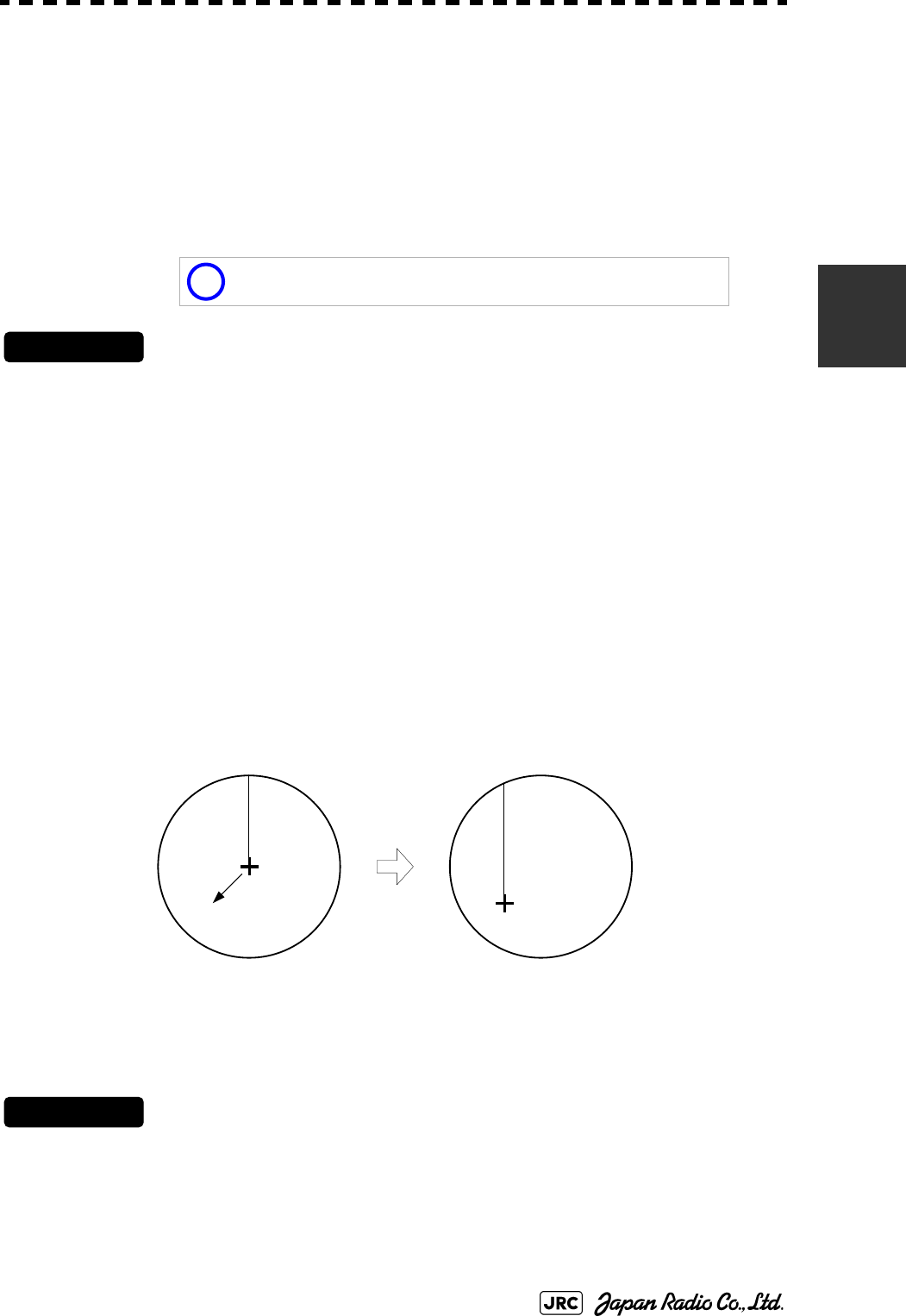
JMA-9100 Instruction Manual > 3.BASIC OPERATION > 3.4 GENERAL RADAR OPERATION
3-29
3
3.4.7 Move Own Ship’s Display Position (Off Center)
The own ship’s position can be moved from the display center to any position
within 66% of the display radius. This function is convenient for observing a wide
coverage in any direction.
If Off Center functions set to scanner position is outside of the PPI range, when
function switching display with reference to scanner position.
Procedures
1) Left-click the Off Center button located at the upper left of the
display.
The cross cursor mark will appear at the own ship’s position on the radar display.
2) Move the cross cursor mark (own ship’s display position) to a
desired position by using the trackball.
While the cross cursor mark is moving, the own ship’s display position moves following
the cross cursor mark.
When it moves to a position outside 66% of the display radius, the center position is limited
to a position within 66% of the display radius.
3) Press the trackball button on the left key.
The own ship’s display position will be fixed to the cross cursor mark.
3.4.7.1 Returning Own Ship's Position to the Center
Procedures
1) Left-click the Off Center button for 2 seconds.
The own ship position is returned to the center of the display.
This function is not available on the 96 NM range.
i
Move the cursor mark to
a desired position
HL
Press the [
ENT]
key
The own ship’s display
p
osition will be fixed.
HL
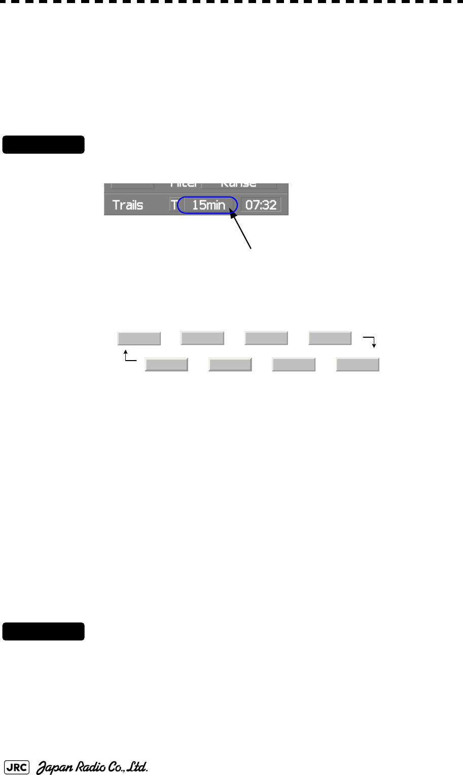
3-30
JMA-9100 Instruction Manual > 3.BASIC OPERATION > 3.4 GENERAL RADAR OPERATION
3.4.8 Display Radar Trails (Trails)
Other ship's movements and speeds can be monitored from the lengths and
directions of their trails, serving for collision avoidance. The trail length varies
according to setting.
3.4.8.1 Changing the length of the trail
Procedures
1) Left-click the Trails button located at the upper left of the
display.
Values of the length of the radar trails are switched.
Trails length setting: Short mode
→ → →
← ← ←
Saved trails cannot be erased even when the trail lengths are changed by using Trails button.
Even after the trails display is turned off, the past trails can be displayed traced back by
setting a desired time.
The radar system is start transmission, trails is start plot.
The system is plotting trails even while the trails display is off.
If the transmit time is short, the indicated trails duration may not have achieved the specified
time. The radar trails remaining time is indicated at the right of the trails length setting.
3.4.8.2 Erasing Trails Data
Procedures
1) Hold down the Trails button for five seconds located at the
upper right of the display.
All the saved trails data will be erased. The system starts plotting trails in initial state.When
Trails button is clicked for 2 seconds, a RADAR Trails Setting menu will be displayed.
Furthermore, data will be erased if it continues pushing.
Short :15秒、30秒、1分、3分、6分、10分、15分
Middle :30秒、1分、3分、6分、10分、15分、30分
Long :1分、3分、6分、10分、15分、30分、60分
RADAR trails display time
Off 15sec 30sec 1min
15min 10min 6min 3min

JMA-9100 Instruction Manual > 3.BASIC OPERATION > 3.4 GENERAL RADAR OPERATION
3-31
3
3.4.8.3 Trails Motion Mode
There are two types of trails: relative motion trails and true motion trails.
Trails modes provided with this system vary depending on the motion mode.
While the true motion trails mode is active, this system enables the continuous use of true
motion trails even if any of the following operations is performed:
•Motion display mode change (TM/RM)
•TM reset
•Bearing display mode change
•Center move (Off Center)
•MAP display on/off (Map)
Relative motion
trails:
The system plots the trails of a target at a position relative to
the own ship. The operator can easily judge whether the target
is approaching the own ship. While the own ship is moving, the
system also plots the trails of land and other fixed targets.
True motion
trails:
The system plots the absolute motion trails of a target,
irrespective of the own ship’s position. The operator can easily
judge the course and speed of the target. The system does not
plot the trails of land and other fixed targets.
With true motion (TM)
mode:
Only the true motion trails mode is available.
With relative motion
(RM) mode:
The relative motion trails mode or true motion trails
mode isselectable.
is indicated while the relative motion
trails mode is active.
is indicated while the true motion trails
mode is active.
i
Accurate true bearing signals and speed signals are necessary
for using the true motion trails mode.
True Motion Trails
HL
Land
Relative Motion Trails
HL
Ship
Trails
Trails
RM(R)
RM(T)

3-32
JMA-9100 Instruction Manual > 3.BASIC OPERATION > 3.4 GENERAL RADAR OPERATION
3.4.8.4 Changing Motion Mode of Trails (Trails Mode)
Procedures
1) Click the Trails Mode located at the upper right of the radar
display.
The trails motion modes are switched.
⇔
RADAR trails true/relative
TR
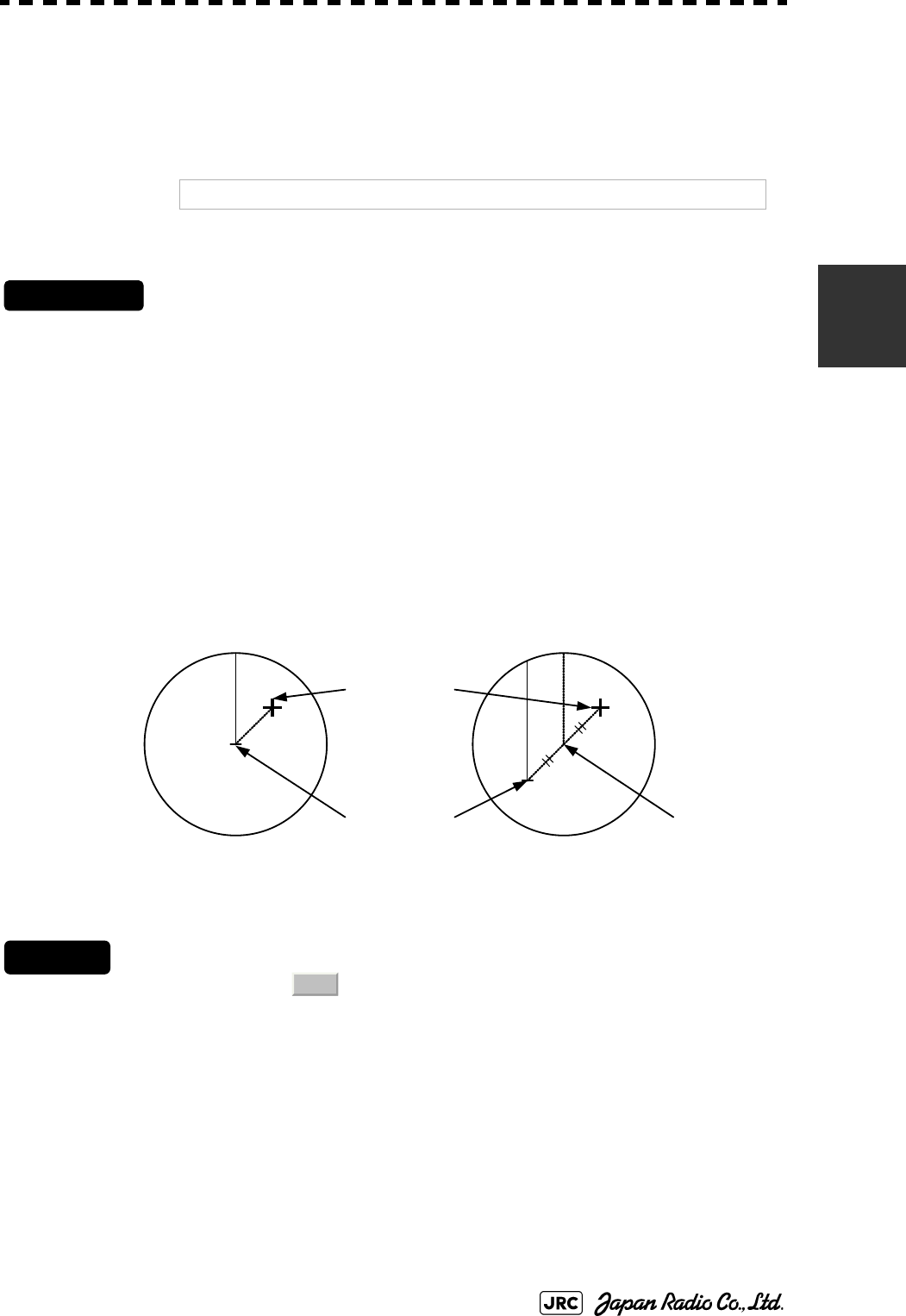
JMA-9100 Instruction Manual > 3.BASIC OPERATION > 3.4 GENERAL RADAR OPERATION
3-33
3
3.4.9 Zoom (x2)
This function doubles the size of radar video near a specified position.
Procedures
1) Left-click the x2 button located at the lower left of the display.
The zoom mode is selected.
2) Subsequently, put the cross cursor mark on a location you want
to zoom into, and press the left key of the trackball.
The zoom is set.
Using the cross cursor mark as reference, the zoom function doubles the size of a radar video
with the midpoint between the cursor mark and own ship’s position being set to the center
of radar display.
Cancel
1) Left-click the button located at the lower left of the
display.
The zoom mode is cancelled.
NOTE: If the range is 0.125 NM , this function is not available.
Own Ship’s Position before
Zooming position
HL
Cursor mark
Own Ship’s Position after
Zooming position
HL
Own ship’s
position
Center of
radar display
x2

3-34
JMA-9100 Instruction Manual > 3.BASIC OPERATION > 3.4 GENERAL RADAR OPERATION
3.4.10 Hide/Display Range Rings [HL OFF]
Procedures
1) Press the [HL OFF] key. Alternatively, Left-click the
button located at the lower right of the display.
The ship's heading line (HL) is hidden while the [HL OFF] key is held down.
The ship's heading line that indicates the course of own ship is always shown on the radar
display. The heading line is hidden while the [HL OFF] key is held down, so the targets on
the heading line can be easily observed.
3.4.11 Hide Graphics Information on Radar Display [DATA OFF]
Various graphics information such as target tracking TT/AIS symbols, NAV lines,
and MAP information is shown on the radar display of this radar system, and may
make it difficult to view the radar video. In that case, use this function to
temporarily hide unnecessary graphics information.
Procedures
1) Press the [DATA OFF] key. Alternatively, Left-click the
button located at the lower right of the display.
While the key is pressed, graphics data other than VRM, EBL, HL, cross cursor mark, and
range rings on the radar display is temporarily hidden.
HL
Off
Data
Off
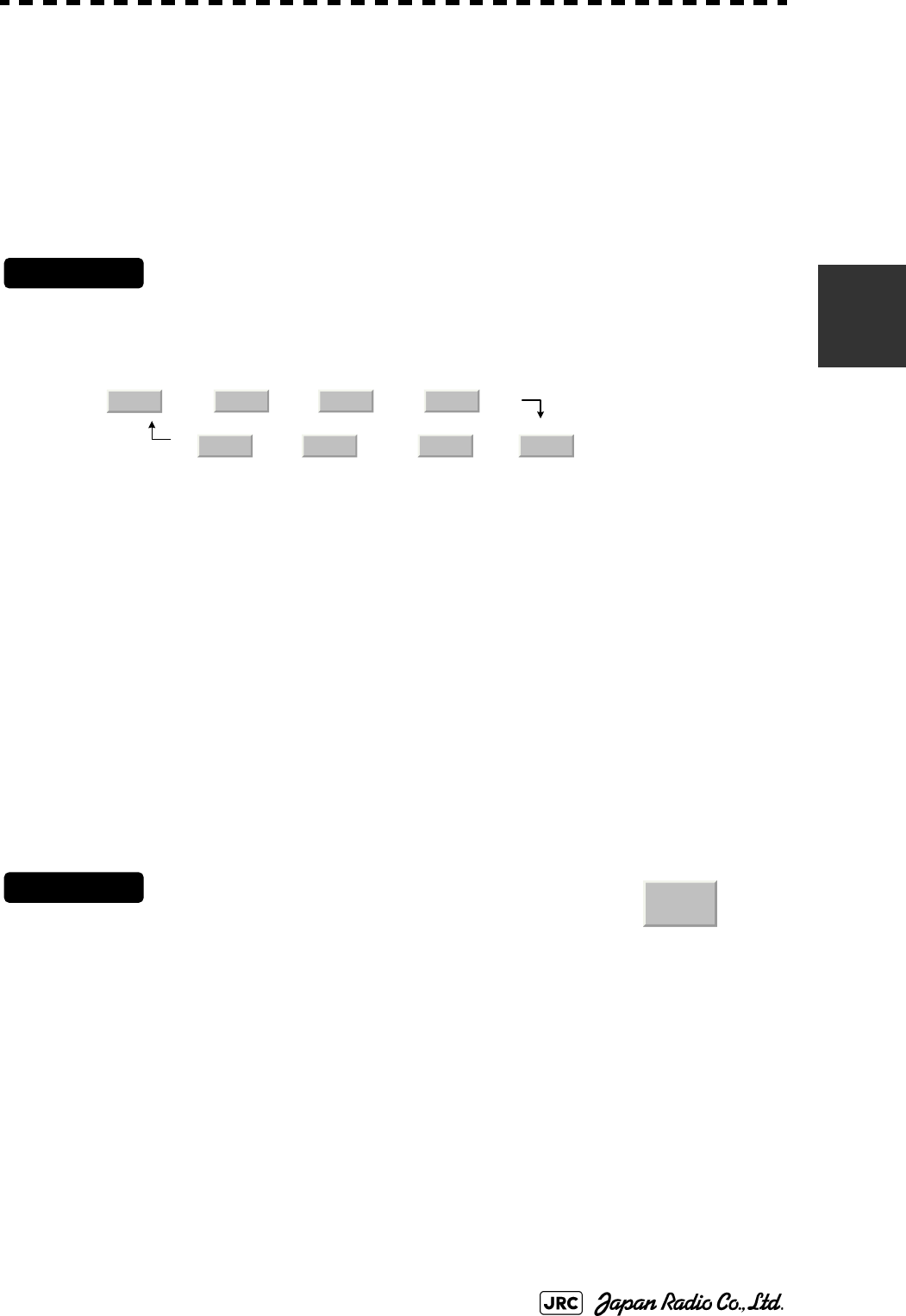
JMA-9100 Instruction Manual > 3.BASIC OPERATION > 3.4 GENERAL RADAR OPERATION
3-35
3
3.4.12 Switch Day/Night Mode [DAY/NIGHT]
Several combinations of the display color and brilliance according to the ambient
lighting conditions are provided. The display color setting is easily changed.
Procedures
1) Press the [DAY/NIGHT] key. Alternatively, left-click the Day/Night
button located at the lower right of the radar display.
The DAY/NIGHT modes are switched.
→ → →
← ← ←
The current mode is displayed at the lower right of the radar display.
For how to set the display color and brilliance for each mode, see Section 3.8.5 "Set Radar
Display (Display Setting)"
3.4.13 Adjust Operation Panel Brilliance [PANEL]
Adjust brilliance of the operation panel according to the ambient lighting
conditions.
Procedures
1) Press the [PANEL] key. Alternatively, left-click the
button located at the lower right of the radar display.
In consideration of the ambient brightness, adjust panel brilliance that is high enough to read
the characters on the operation panel but does not glare.
The [PANEL] key lamp lights up irrespective of panel brilliance adjustment.
Day1 Day2 Day3 Dusk
Day2 Day3 Dusk Night
Panel
○
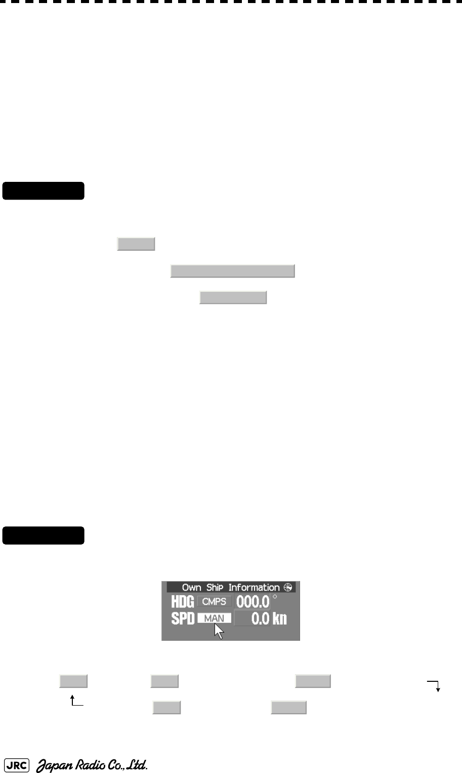
3-36
JMA-9100 Instruction Manual > 3.BASIC OPERATION > 3.4 GENERAL RADAR OPERATION
3.4.14 Set True Bearing
When the GYRO I/F is used to enter a gyro signal, there is a rare case in which a
true bearing value indicated by the master gyro does not match the true bearing
value indicated by this radar system.
In that case, adjust the true bearing value of this system so that it matches the
value indicated by the master gyro.
Procedures
1) Open the numeric value input screen to enter a true bearing
value by performing the menu operation below.
→
→
2) Enter a value indicated by the master gyro on the numeric value
input screen.
For how to input numeric data on the numeric value input screen, see Section
3.3.4 "Operation on Numeric Value, Latitude / Longitude and Character Input
menu".
3.4.15 Set Own Ship Speed
3.4.15.1 Switch the own ship speed device
Procedures
1) Left-click the own ship speed device button in the Own Ship
Information area located at the upper right of the display.
The speed sensor is switched whenever the button is clicked.
(Manual) → (Single-axis water log) → (Dual-axis water log)
(GPS) ← (Dual-axis ground log)
Main
6.NAV Equipment Setting
1. Gyro Setting
MAN LOG 2AXW
GPS 2AXG

JMA-9100 Instruction Manual > 3.BASIC OPERATION > 3.4 GENERAL RADAR OPERATION
3-37
3
3.4.15.2 Input the own ship speed (Manual Speed)
If the ship-speed system, such as LOG, etc., connected to this radar system
malfunctions, it is possible to manually enter own ship speed by the method
described below to use the target tracking (TT) and true motion display functions.
Procedures
1) Left-click the own ship speed device button in the Own Ship
Information area located at the upper right of the display, and
select the manual mode .
2) Left-click the value of the speed.
The numeric value input screen will open to enter the own ship speed.
3) Enter the value for the own ship speed on the numeric value
input screen.
For how to input numeric data on the numeric value input screen, see Section 3.3.4
"Operation on Numeric Value, Latitude / Longitude and Character Input menu".
3.4.16 Magnet Compass Correction (MAG Compass Setting)
Set the correction value, when the radar receive HDM sentence from magnet
compass or the variation of HDG is NULL.
Procedures
1) Open the MAG Compass Setting menu by performing the
following menu operation.
→
→
NOTE: •If the single axis water log display can present the speed of
the ship in other than the forward direction, the direction of
movement should be indicated unambiguously. Therefore
single axis water logs cannot detect the effect of leeway.
•If ships in shallow water, when the accuracy of the dual-axis
log may be decreased. If ships in deep sea area, when the
accuracy of the dual-axis log error may be occurred.
•The accuracy of GPS's COG is ±3° when own ships speed
no fewer than 1kn, no more than 17kn. The accuracy of
GPS's COG is ±1° when own ships speed over 17kn.
MAN
Main
6.NAV Equipment Setting
2. MAG Compass Setting

3-38
JMA-9100 Instruction Manual > 3.BASIC OPERATION > 3.4 GENERAL RADAR OPERATION
2) Set whether to make corrections or not.
⇔
3) Input the correction value.
Press the or button to select south and north for latitude or the east and west
for longitude.
For how to input numeric data on the numeric value input screen, see Section 3.3.4
"Operation on Numeric Value, Latitude / Longitude and Character Input menu".
3.4.16.1 Set Drift Correction
The direction and speed of the drift are set.
This function can be used only when or is selected for ship-speed
data.
Procedures
1) Open the Set/Drift Setting menu by performing the menu
operation below.
→
→
2) Set whether to make corrections or not.
⇔
For menu operation, see Section 3.3.3 "Basic Menu Operation".
3) Enter the correction value for tidal current.
For how to input numeric data on the numeric value input screen, see Section 3.3.4
"Operation on Numeric Value, Latitude / Longitude and Character Input menu".
: Direction of tidal current (true bearing)
: Speed of tidal current
1. Heading Correction
Off On
+
-
MAN LOG
Main
6.NAV Equipment Setting
3. Set/Drift Setting
1. Correction
Off On
2.Set
3.Drift
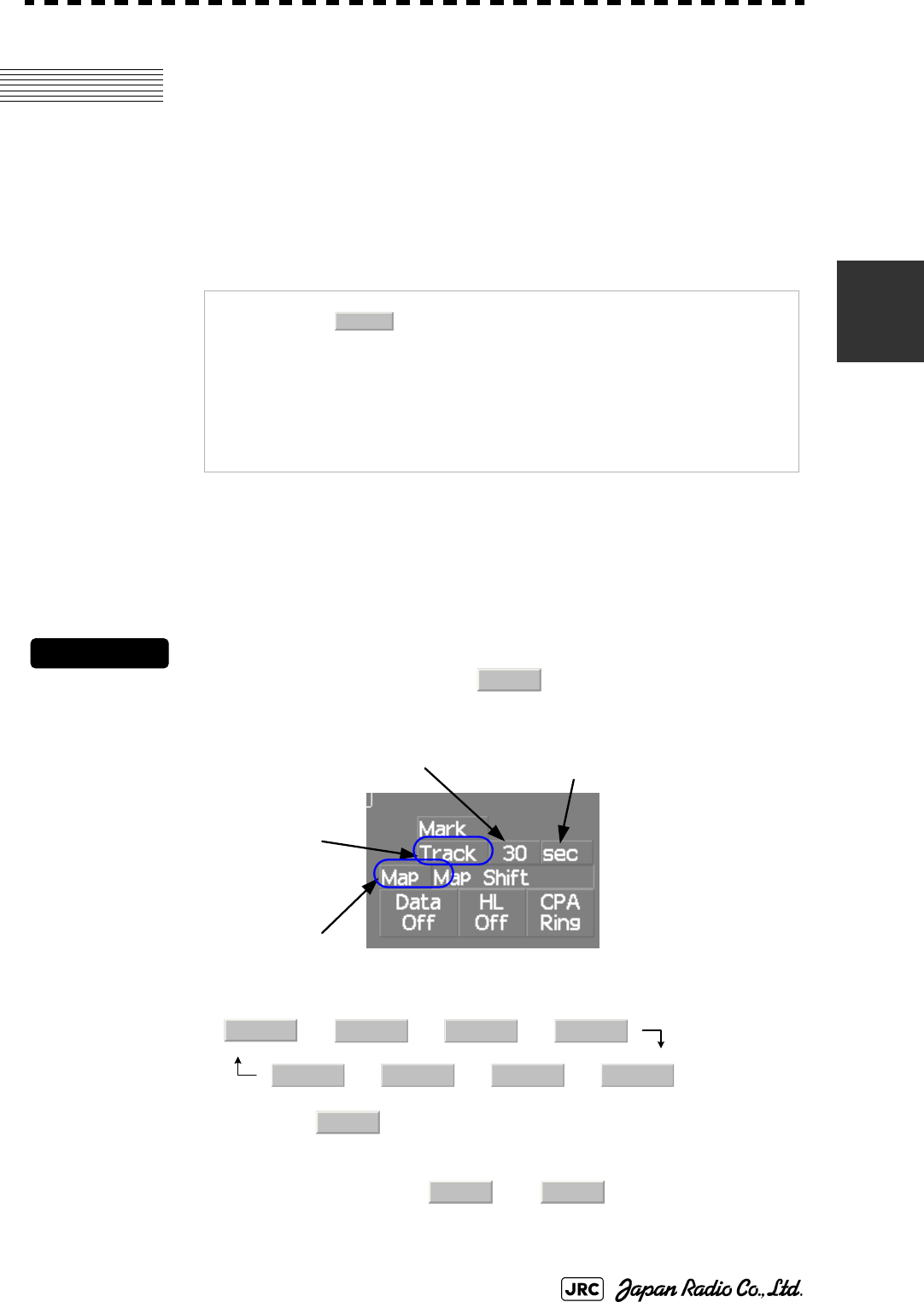
JMA-9100 Instruction Manual > 3.BASIC OPERATION > 3.5 USE OWN SHIP'S TRACK
3-39
3
3.5 USE OWN SHIP'S TRACK
The own ship's track function saves and displays own ship's track.
If navigation equipment is connected, this radar system records latitude/longitude
data sent from the navigation equipment and displays own ship's track.
3.5.1 Display Own Ship's Track (Display Own Track)
Procedures
1) Left-click the Own Track Color button located at the
lower right of the display.
The color of the own ship's track are switched.
→ → →
← ← ←
2) Left-click the button located at the lower right of the
display.
The map display function is turned on or off .
When Color is selected, the own ship's track is displayed.
NOTE: Even when own ship's track storage interval is turned
, own ship's track can be displayed. However, in this
case, if rewrite operation such as changing of the display
range is performed for the radar display, own ship's track
display is erased and the track will not be plotted again.
If the own ship track display is turned off when own ship
track is in storage, own ship's tracks are not shown on the
radar display, but own ship's track is still saved.
Off
Track
Own Track Interval
Map On/Off
Own Track Color
Own Track Interval Unit
Off White Gray Blue
Red Pink Yellow Green
Map
Map Map
3-40
JMA-9100 Instruction Manual > 3.BASIC OPERATION > 3.5 USE OWN SHIP'S TRACK
3.5.2 Set Display Color of Own Ship's Track (Display Own Track
Color)
Own ship's track can be saved in seven different colors.
Own ship's track can be displayed or not displayed individually by color.
Procedures
1) Open the Display Own Track Setting menu by performing the
menu operation
→
The Display Own Track Setting menu will open.
Operations differ according to the following set modes.。
2) Left-click the color button for the desired display setting which is
to be changed.
Display of each item is switched between and
When is set to All of own ship's tracks are displayed.
When is set to All of own ship's tracks are not displayed.
When is set to Settings are made by color by performing the
operation below.
On : Own ship's track plotted by the color is displayed.
Off : Own ship's track plotted by the color is not displayed.
Track
1. DISP Own Track Color
1. All On
1. All Off
1. All
Individual
On Off
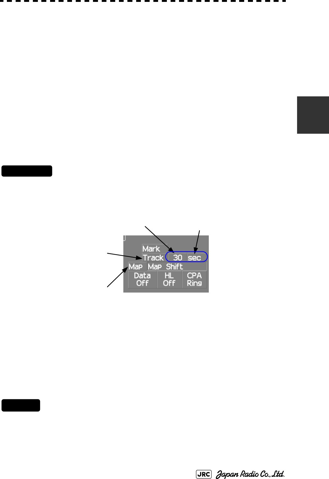
JMA-9100 Instruction Manual > 3.BASIC OPERATION > 3.5 USE OWN SHIP'S TRACK
3-41
3
3.5.3 Save Own Ship's Track (Own Track Memory)
To save own ship's track, storage at a specified time interval and at a specified
range interval can be selected.
The track storage interval can be selected from 10 preset time intervals and 8
preset range intervals.
Procedures
1) Left-click the Own Track Interval unit button located at the lower
right of the display.
Every time the button is clicked, the units of measure for the storage are switched.
2) Left-click the Own Track Interval button located at the lower right
of the display.
Every time the button is clicked, storage intervals are switched.
When Off is selected, the storage function is turned off.
3.5.4 Cancel Saving of Own Ship's Track (Own Track Memory)
Storage of own ship's track can be turned off.
Cancel
1) Left-click the Own Track Interval button located at the lower right
of the display.
Every time the button is clicked, interval for track storage are switched.
When Off is selected, the storage function is turned off.
Storage intervals that can be selected
Time : 3 sec, 5 sec, 10 sec, 30 sec, 1 min, 3 min, 5 min, 10 min, 30 min, and 60 min
Range : 0.1 NM, 0.2 NM, 0.3 NM, 0.5 NM, 1 NM, 3 NM, 5 NM, and 10 NM
Own Track Interval
Map On/Off
Own Track Color
Own Track Interval Unit

3-42
JMA-9100 Instruction Manual > 3.BASIC OPERATION > 3.5 USE OWN SHIP'S TRACK
3.5.5 Clear Own Ship's Track (Clear Own Track)
This function cancels the storing of own ship's track.
Procedures
1) Open the Clear Own Track Color menu by performing the menu
operation below.
→
The Clear Own Track Color menu will appear.
2) Left-click the button for the color to be deleted.
: All tracks are deleted
/ / / / / / :
Only track of specified color is deleted.
After the item has been selected, Clear Own Track Confirmation Window will appear.
3) Left-click the Yes button.
Own ship's track indicated by the specified color will be deleted.
3.5.6 Use Expanded Own Ship's Track (Own Track Type)
The following expanded track functions can be used for this radar system.
Only one type of expanded own ship's track can be used at a time. Multiple types
of expanded tracks cannot be used at the same time.
Specify the type of the expanded own ship's tracks to be used by performing the
operation below.
Water temperature track : The water temperature value at the latitude/longitude is
recorded.
Water depth track : The water depth value at the latitude/longitude is recorded.
Tidal current track : The tidal current vector at the latitude/longitude is recorded.
Track
2. Clear Own Track Color
All
White Gray Blue Red Pink Yellow Green
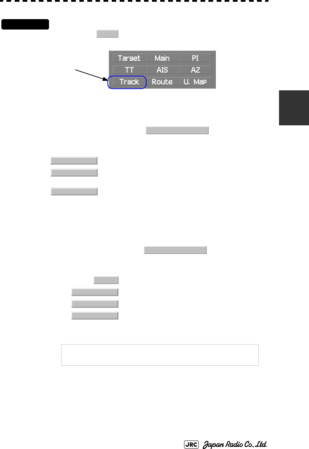
JMA-9100 Instruction Manual > 3.BASIC OPERATION > 3.5 USE OWN SHIP'S TRACK
3-43
3
Procedures
1) Left-click the button located at the lower right of the
display.
The Own Track Menu will appear.
2) Left-click the item button of .
The numeric value of the navigation data can be shown by the color of own ship's track.
3) Select the function to be used.
4) Left-click the item button of
Numeric value or vector of navigation data can be added to own ship's track.
5) Select the function to be used.
: The expanded own ship's track function is not used.
: The color of the tracks is changed according to the water
depth value
:The color of the tracks is changed according to the water
temperature value.
: Numeric value and vector are not added.
: Water depth value is added.
: Water temperature value is added.
:current vector is added.
NOTE: To use the expanded own ship's track function, the track
must be entered from the special navigation equipment
into this radar system.
Track
Track menu
3. Track Type
Normal
Depth
Temperature
4. Num Vector Display
Off
Depth
Temperature
Current

3-44
JMA-9100 Instruction Manual > 3.BASIC OPERATION > 3.5 USE OWN SHIP'S TRACK
3.5.7 Use Water Depth Track (Water Depth Track)
Set the corresponding conditions for the water depth value and the color of own
ship's track by performing the operation below.
Procedures
1) Open the Water Depth Setting menu by performing the menu
operation below.
→
The Water Depth Setting menu will appear.
Enter a value of the boundary water depth for each item according to the table below to set
up the corresponding conditions for the water depth value and the color of own ship's track.
For example, if 10m is entered for 1. , 30m is entered for 2. , and 50m is entered for 3. , the
area with a water depth of less than 10 meters is indicated by white tracks, the area with a
water depth of 10 to 30 meters is indicated by light blue tracks, and the area with a water
depth of 30 to 50 meters is indicated by blue tracks.
Water depth
value
Color of track
White
1. xxxx m Min
Gray
2. xxxx m
Blue
3. xxxx m
Green
4. xxxx m
Yellow
5. xxxx m
Pink
6. xxxx m Max
Red
Track
6. Water Depth Setting

JMA-9100 Instruction Manual > 3.BASIC OPERATION > 3.5 USE OWN SHIP'S TRACK
3-45
3
3.5.8 Use Water Temperature Track (Water TEMP Track)
Set the corresponding conditions for the water temperature value and the color of
own ship's track by performing the operation below.
Procedures
1) Open the Water TEMP. Setting menu by performing the menu
operation below
→
The Water TEMP. Setting menu will appear.
Enter a value of the boundary water temperature for each item according to the table below
to set up the corresponding conditions for the water temperature value and the color of own
ship's track.
For example, if 10.0 ~ is entered for 1. , 13.0 ~ is entered for 2. , and 15.0 ~ is entered for
3. , the area with a water temperature of less than 10.0 ?? is indicated by white tracks, the
area with a water depth of 10.0 ~ to 13.0~ is indicated by light blue tracks, and the area with
a water depth of 13.0 ~ to 15.0 ~ is indicated by blue tracks.
Water temperature
value
Color of track
White
1. xx.x ℃Min
Gray
2. xx.x ℃
Blue
3. xx.x ℃
Green
4. xx.x ℃
Yellow
5. xx.x ℃
Pink
6. xx.x ℃Max
Red
Track
7. Water TEMP. Setting

3-46
JMA-9100 Instruction Manual > 3.BASIC OPERATION > 3.5 USE OWN SHIP'S TRACK
3.5.9 Use Tidal Current Track (Current Vector Track)
Set the conditions for adding tidal current vectors to own ship's track by
performing the operation below.
Procedures
1) Open the Current Setting menu by performing the menu
operation below.
→
The Current Setting menu will appear.
Set the tidal current vector display conditions.
[1]Length of the tidal current vector (Current Size)
•Set the length of the tidal current vector.
•The unit of measure is kn/cm.
•If 1.0kn/cm is set, a tidal current of 1.0kn is shown as a one-centimeter line
on the radar display.
[2]Color of the vector for tidal current layer A (Layer A)
•Set the vector's display color for tidal current layer A.
•Choose one of the following colors
White、Gray、Blue、Green、Yellow、Pink、Red
[3]Color of the vector for tidal current layer B (Layer B)
•Set the vector's display color for tidal current layer B.
•Choose one of the following colors
White、Gray、Blue、Green、Yellow、Pink、Red
[4]Color of the vector for tidal current layer C (Layer C)
•Set the vector's display color for tidal current layer C.
•Choose one of the following colors
White、Gray、Blue、Green、Yellow、Pink、Red
Track
8. Current Setting
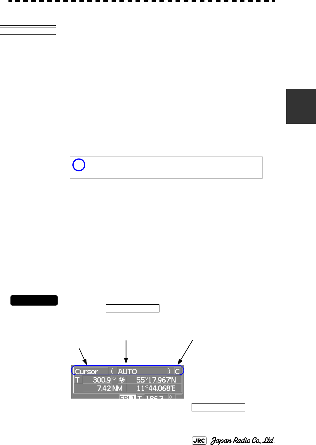
JMA-9100 Instruction Manual > 3.BASIC OPERATION > 3.6 DISPLAY USER MAP
3-47
3
3.6 DISPLAY USER MAP
Up to 20,000 items of NAV lines, coastlines, depth contours, and NAV marks can
be created, displayed, loaded, and saved. (This function is available only when
navigation equipment is connected to this radar system.)
3.6.1 Create User Map (Mark/Line)
In this system, when the radar is in the transmission state, the user map is
displayed all the time. However, valid latitude/longitude data and true bearing
data must be entered into the system.
The user map can be created and edited by performing the following operation.
3.6.1.1 Plotting a mark
Procedures
1) Left-click the button located at the upper right
of the display to set the Mark mode.
The mark font to be used is displayed to the right of the button.
Marks that can be used : 29 types
Lines that can be used : 3 types (solid, broken, and dashed-dotted line)
Color of mark and lines
that can be used
: 7 colors
i
If radar video is poor visibility caused by user map function,
press the [DATA OFF] key to map displays temporarily off.
Cursor
Cursor mode switching
Mark color / line color
switching
Mark font / line pattern
switching
Cursor
3-48
JMA-9100 Instruction Manual > 3.BASIC OPERATION > 3.6 DISPLAY USER MAP
2) Left-click the mark font button to select a font for the
mark.
The mark fonts are switched.
3) Left-click the button located to the right of the mark font to
select a color for the mark.
The color for the mark font located to the right of the button will
change.
4) Left-click at a desired location on the radar display.
The specified mark will be displayed in the specified color.
To create another mark, repeat the above procedures.
3.6.1.2 Plotting a line
Procedures
1) Left-click the button located at the upper right
of the display to select the line mode.
The line pattern to be used is displayed to the right of the button.
2) Left-click the button located at the upper right of the
display to select the line pattern.
The line pattern to be used is displayed to the right of the button.
3) Left-click the button located to the right of the line pattern to
select a color for the line.
The color for the line pattern located to the right of the button will
change.
4) Left-click at a desired location on the radar display.
Line colors are switched.
□
C
Cursor
Cursor
Cursor
-------
Cursor
C
Cursor

JMA-9100 Instruction Manual > 3.BASIC OPERATION > 3.6 DISPLAY USER MAP
3-49
3
5) Move the cursor to a desired location on the radar display and
left-click.
A line is plotted between the previous point and the end point. Repeat this procedure so that
sequential lines can be plotted.
6) When you want to finish plotting the line, left-click at the
previous point.
Line plotting will be terminated. To plot another line, repeat procedures 3.
3.6.1.3 Plotting a mark / line make with latitude and longitude
Procedures
1) Open the Edit User Map menu by performing the following menu
operation.
→
→
2) Left-click the button.
The Mark Input menu and the Line Input menu are switched.
3) Left-click the item button of to select the type of
mark font or line pattern to be created.
The desired mark font or line pattern is selected.
To add a line, select midpoint --O-- .
4) Left-click the item button of to select the color of
mark or line to be created.
The desired mark or line color is selected.
U.Map
2. Edit User Map
2. Make with L/L
9. New Mark Input
1. Type
2. Color

3-50
JMA-9100 Instruction Manual > 3.BASIC OPERATION > 3.6 DISPLAY USER MAP
5) Left-click the button to input the latitude /
longitude.
For the input method on the latitude / longitude input screen, see Section 3.3.4.5 "Entering
latitude/longitude"
6) Left-click the button to input the comment.
For the input method on the character input screen, see Section 3.3.4.7 "Entering a character"
The window will not be open when the system is in the transmission state.
7) Left-click the button.
Mark / Line plotting will be terminated.
To create another mark or line, repeat procedures 4 to 7.
3.6.2 Set User Map Display (Mark Display Setting)
The user map can be individually displayed (On) or hidden (Off).
The mark font display size can be selected.
3.6.2.1 Setting display by type
Procedures
1) Open the Display Mark Type menu by performing the menu
operation below.
→
→
The Display Mark Type menu will open.
Setting by type : Setting can be made by mark font and line pattern.
Setting by color : Setting can be made by color of mark or line.
Normal: The mark is displayed in normal size.
Small: The mark is displayed in a size smaller than usual.
3. L/L
4. Comment
5. Enter
U.Map
5. Mark Display Setting
1. Display Mark Type
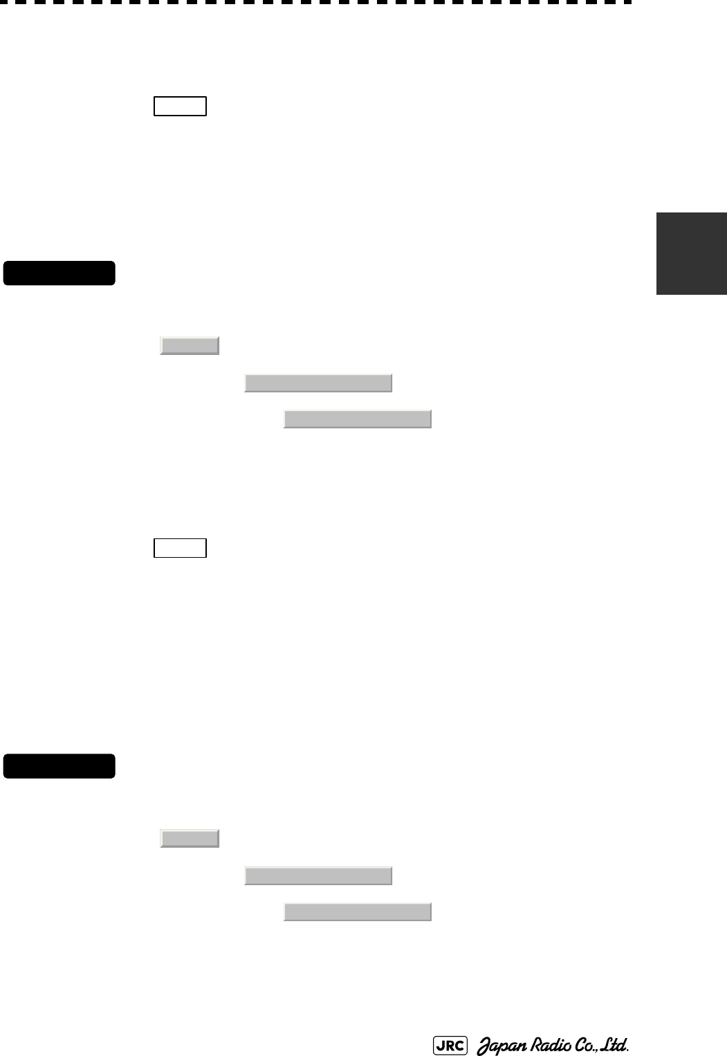
JMA-9100 Instruction Manual > 3.BASIC OPERATION > 3.6 DISPLAY USER MAP
3-51
3
2) Specify whether to turn on or off the display for each type of
mark and line.
When is selected, the setting will reflect to all types of marks and lines.
3.6.2.2 Setting display by color
Procedures
1) Open the Display Mark Color Type menu by performing the menu
operation below.
→
→
The Display Mark Color Type menu will open.
2) Specify whether to turn on or off the display for each color type
of mark and line.
When is selected, the setting will reflect to all color types of marks and
lines.
3.6.2.3 Setting the mark font size
Procedures
1) Open the Mark Size menu by performing the menu operation
below.
→
→
The Mark Size menu will appear.
Off : All types are not displayed.
Individual : All types are displayed.
On : Setting by type is activated.
Off : All color types are not displayed.
Individual : Setting by color type is activated.
On : All color types are displayed.
1. All
U.Map
5. Mark Display Setting
2. Display Mark Color
1. All
U.Map
5. Mark Display Setting
3. Mark Size

3-52
JMA-9100 Instruction Manual > 3.BASIC OPERATION > 3.6 DISPLAY USER MAP
2) Specify the mark font size.
3.6.2.4 Setting the character size for comments
Procedures
1) Open the Comment Font Size menu by performing the menu
operation below.
→
→
The Comment Font Size menu will appear.
2) Specify the comment font size.
3.6.3 Edit User Map (Edit User Map)
3.6.3.1 Manually entering the own ship position (Own Ship Position)
Use this function when editing navigation data for a location different from the own ship
position.
Procedures
1) Open the Own Ship Position menu by performing the menu
operation below.
→
The number key screen for entering the latitude/longitude of the Own Ship Position will
appear.
Normal : The mark is displayed in normal size.
Small : The mark is displayed in a size smaller than usual.
Normal : The characters for comments are displayed in normal size.
Small : The characters for comments are displayed in a size smaller
than usual.
U.Map
5. Mark Display Setting
4. Comment Font Size
U.Map
1. Own Ship Position

JMA-9100 Instruction Manual > 3.BASIC OPERATION > 3.6 DISPLAY USER MAP
3-53
3
2) Use the number buttons to to enter a value of latitude
(xx°xxx.xxx').
3) To make changes between north latitude and south latitude, use
the and buttons.
4) Left-click the button.
The manually entered latitude will be determined. Then, enter the value of longitude.
5) Use the number buttons to to enter a value of longitude
(xx°xxx.xxx').
6) To make changes between east longitude and west longitude,
use the and buttons.
7) Left-click the button.
The manually entered longitude will be determined.
3.6.3.2 Moving a mark or line (Move)
With regard to the created user map, a mark or line is moved individually.
Procedures
1) Open the Edit User Map menu by performing the following menu
operation.
→
The Edit User Map menu will appear.
2) Left-click the button.
North latitude : Left-click the button.
South latitude : Left-click the button.
East longitude: Left-click the button.
West longitude: Left-click the button.
NOTE: The own ship's position manually entered by using the
function above is valid only in the navigation data setting
menu. After exiting from the menu, the manually entered
position data is invalidated.
09
+ -
+
-
ENT
0
9
+ -
+
-
ENT
U.Map
2. Edit User Map
3. Move
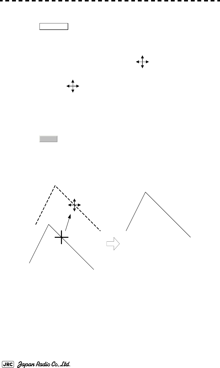
3-54
JMA-9100 Instruction Manual > 3.BASIC OPERATION > 3.6 DISPLAY USER MAP
The user map move mode is selected.
is displayed in the cursor mode located at the upper right of the display.
3) Put the cursor on a mark or line, and left-click.
When a mark or line to be moved is selected, the cursor mark will appear.
4) Move the cursor mark to the destination, and left-click.
The selected mark or line is moved to the destination.
To move another mark or line, repeat procedures 3 and 4.
5) When finished with the correction of all items, left-click the
button.
The cursor mode changes to the normal operation mode, terminating the user map move
mode.
(Example)
Move Map
0.Exit

JMA-9100 Instruction Manual > 3.BASIC OPERATION > 3.6 DISPLAY USER MAP
3-55
3
3.6.3.3 Deleting a mark or line (Delete)
With regard to the created user map, a mark or line is deleted individually.
Procedures
1) Open the Edit User Map menu by performing the following menu
operation.
→
The Edit User Map menu will appear.
2) Left-click the button.
The user map delete mode is selected.
is displayed in the cursor mode located at the upper right of the display.
3) Put the cursor on a mark or line, and left-click.
The entire selected mark or line is deleted.
To delete another mark or line, repeat procedures 3 and 4.
4) When finished with the correction of all items, left-click the
button.
The cursor mode changes to the normal operation mode, terminating the user map delete
mode.
U.Map
2. Edit User Map
4. Delete
Delete
0.Exit
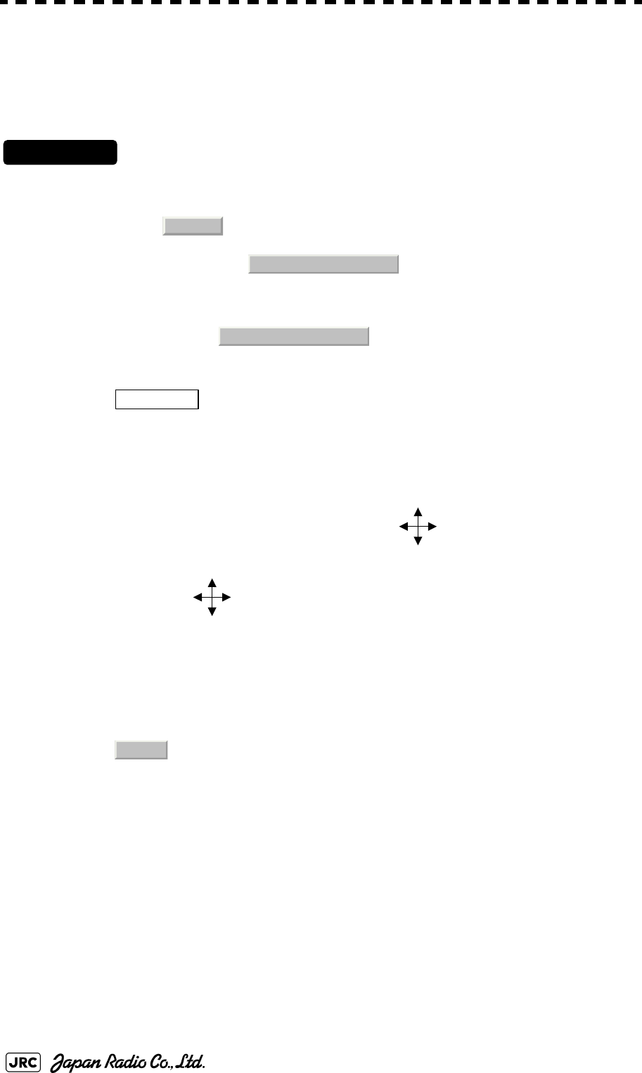
3-56
JMA-9100 Instruction Manual > 3.BASIC OPERATION > 3.6 DISPLAY USER MAP
3.6.3.4 Inserting a vertex into a line (Insert/Move Vertex)
With regard to the created user map, a vertex is inserted into a line.
Procedures
1) Open the Edit User Map menu by performing the following menu
operation.
→
The Edit User Map menu will appear.
2) Left-click the button.
The user map insert/correction mode is selected.
is displayed in the cursor mode lacated the upper right of the display.
3) Put the cursor to a side line into which a vertex will be inserted,
and left-click.
A vertex is inserted into the selected line, and the cursor mark will be displayed.
4) Move the cursor mark to the newly inserted vertex, and left-
click.
To insert another vertex, repeat procedures 3 and 4.
5) When finished with the correction of all items, left-click the
button.
The cursor mode changes to the normal operation mode, terminating the user map insertion/
correction mode.
U.Map
2. Edit User Map
5. Insert /Move Vertex
Insert/Move
0.Exit
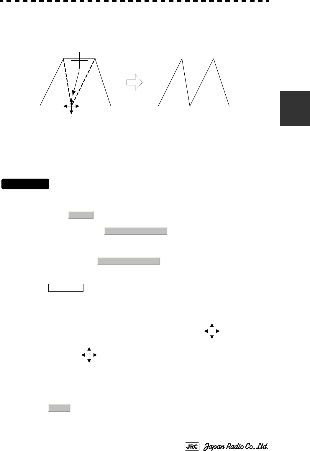
JMA-9100 Instruction Manual > 3.BASIC OPERATION > 3.6 DISPLAY USER MAP
3-57
3
(Example)
3.6.3.5 Correcting the mark or vertex of a line (Insert/Move Vertex)
With regard to the created user map, a mark or line is corrected.
Procedures
1) Open the Edit User Map menu by performing the following menu
operation.
→
The Edit User Map menu will appear.
2) Left-click the button.
The user map insertion/correction mode is selected.
is displayed in the cursor mode located at the upper right of the display.
3) Put the cursor on the mark or vertex of a line, and left-click.
When the mark or vertex of a line to be corrected is selected, the cursor mark will
appear.
4) Move the cursor mark to the destination, and left-click.
The selected mark or vertex of the line is moved to the destination.
To correct another mark or vertex of a line, repeat procedures 3 and 4.
5) When finished with the correction of all items, left-click the
button.
The side line into which
a vertex is inserted
Inserted vertex
U.Map
2. Edit User Map
5. Insert /Move Vertex
Insert/Move
0.Exit
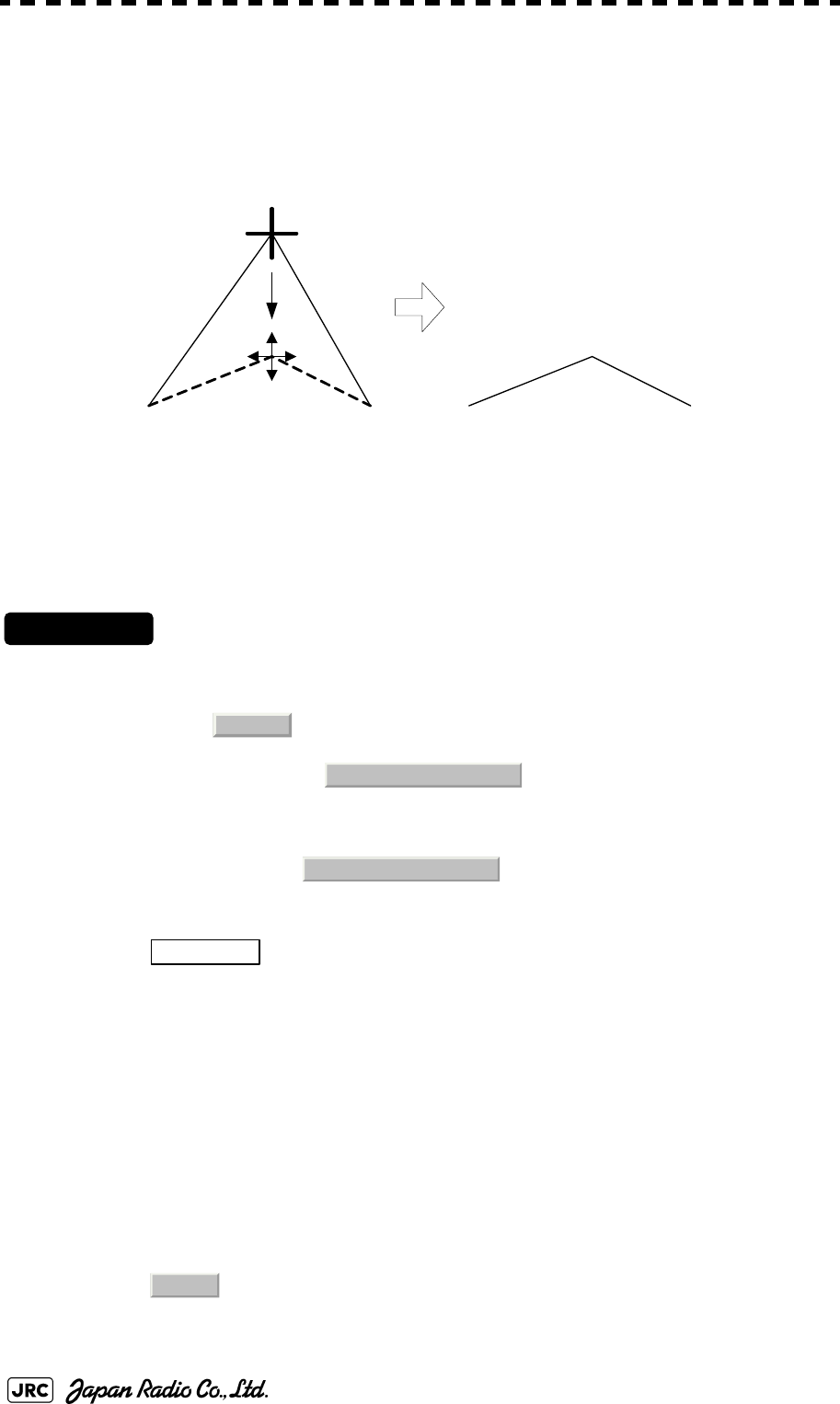
3-58
JMA-9100 Instruction Manual > 3.BASIC OPERATION > 3.6 DISPLAY USER MAP
The cursor mode changes to the normal operation mode, terminating the user map
insertion/correction mode.
(Example)
3.6.3.6 Deleting a mark or vertex from a line (Delete Vertex)
With regard to the created user map, a vertex is deleted individually from a mark or line.
Procedures
1) Open the Edit User Map menu by performing the following menu
operation.
→
The Edit User Map menu will appear.
2) Left-click the button.
The user map delete mode is selected.
is displayed in the cursor mode located at the upper right of the radar display.
3) Put the cursor on the vertex of a mark or line, and left-click.
The selected mark or vertex of the line is deleted.
All of the lines drawn by joining two points are deleted.
To delete another mark or vertex of a line, repeat procedure 3.
4) When finished with the correction of all items, left-click the
button.
Original vertex
New vertex
U.Map
2. Edit User Map
6. Delete Vertex
Delete
0.Exit
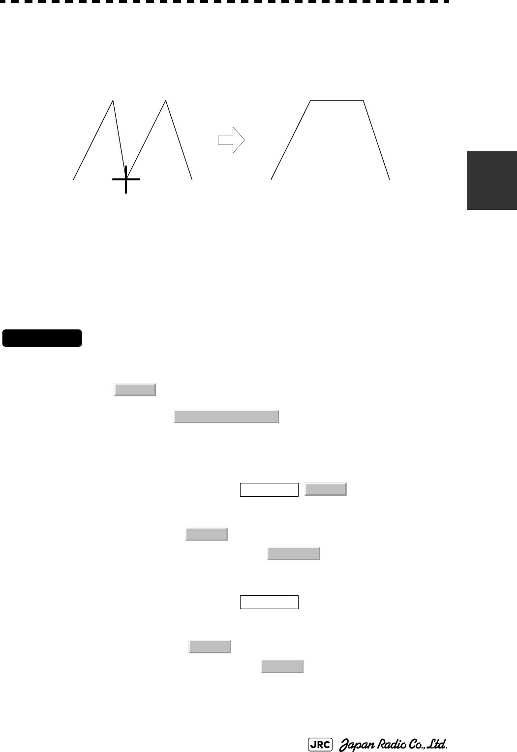
JMA-9100 Instruction Manual > 3.BASIC OPERATION > 3.6 DISPLAY USER MAP
3-59
3
The cursor mode changes to the normal operation mode, terminating the user map delete
mode.
(Example)
3.6.3.7 Batch clearing marks or lines (Clear)
With regard to the created user map, marks or lines are batch cleared by type or by color.
Procedures
1) Open the Edit User Map menu by performing the following menu
operation.
→
The Edit User Map menu will appear.
2)-1 Left-click the item button of
Select the type of marks or lines to be deleted.
To select all types, select .
For example, to delete "red ○" marks, select .
2)-2 Left-click the item button of
Select the color of marks or lines to be deleted.
To select all colors, select .
For example, to clear "red ○" marks, select .
After the items have been selected, Confirmation Window will appear.
The vertex to be deleted
U.Map
2. Edit User Map
7. Delete by Type
All
○
7. Delete
All
Red
3-60
JMA-9100 Instruction Manual > 3.BASIC OPERATION > 3.6 DISPLAY USER MAP
3) Left-click the button.
The selected mark will be deleted.
3.6.4 Correct Position on User Map (Shift User Map)
3.6.4.1 Correcting the display position on the user map (Shift)
If the display position on the user map is different from an actual position, it can be changed
to the correct position in manual mode.
Procedures
1) Open the [Shift] menu by performing the menu operation below.
→
is displayed for the Cursor mode, indicating that the user map shift mode is
selected.
2) Put the pointer on a mark or end of a line, coastline, or depth
contour line, and left-click.
3) Move the cross cursor mark to the location to be corrected, and
left-click.
Positions of all marks and lines currently displayed will be corrected.
At this time, Map Shift is displayed in the map position correction (lower right of the
display), indicating that the position is being corrected.
NOTE: If data is not copied on the flash memory card (option), the data
is not be reloaded.
:Heading correction is conducted
:Heading correction is not conducted
1. Yes
U.Map
3. Shift
Shift
Map Shift
Map Shift

JMA-9100 Instruction Manual > 3.BASIC OPERATION > 3.6 DISPLAY USER MAP
3-61
3
3.6.4.2 Restoring the corrected user map to its original state (Shift Clear)
Procedures
1) Open the Mark Operations menu by performing the following
menu operation.
→
Only the most recently corrected data (for a single input) will be cleared, and the data will be
displayed at its original position.
At this time, Map Shift is not displayed in the map position correction (lower right of the
display).
3.6.5 Save User Map
3.6.5.1 Loading navigation data (Load User Map)
Procedures
1) Insert a flash memory card into the card slot.
Flash memory card (option) is necessary.
2) Open the File Operations menu by performing the following
menu operation.
→
3) Left-click the item button of and select the
card slot.
Slot1 and Slot2 of the Select Card Slot items are switched.
4) Left-click the item button of and select
/.
and of the Load Mode items are switched.
When [Add] is selected, new data is added to the savedd data. When [Overwrite] is selected,
the saved data is overwritten.
:Heading correction is conducted
:Heading correction is not conducted
U.Map
4. Shift Clear
Map Shift
Map Shift
U.Map
7. File Operation
1. Select Card Slot
2. Load Mode
Add
Overwrite
Add
Overwrite

3-62
JMA-9100 Instruction Manual > 3.BASIC OPERATION > 3.6 DISPLAY USER MAP
5) Left-click the button.
The list of navigation data saved in the system will be displayed.
6) Left-click the button for the file to be loaded.
Confirmation Window will appear.
7) Left-click the button.
The selected navigation data will be loaded and displayed on the radar display.
3.6.5.2 Discarding navigation data (Unload User Map)
Procedures
1) Open the File Operations menu by performing the following
menu operation.
→
2) Left-click the button.
Unload Confirmation Window will appear.
3) Left-click the button.
The saved navigation data will be discarded.
3.6.5.3 Storing navigation data (Save User Map)
Navigation data can be saved when navigation equipment is connected, or the own ship
position on the user map is entered in the manual mode.
Procedures
1) Insert a flash memory card into the card slot.
Flash memory card (option) is necessary.
3. Load
1. Yes
U.Map
7. File Operation
4. Unload
1. Yes
JMA-9100 Instruction Manual > 3.BASIC OPERATION > 3.6 DISPLAY USER MAP
3-63
3
2) Open the File Operations menu by performing the following
menu operation.
→
3) Left-click the item button of and select the
card slot.
Slot1 and Slot2 of the Select Card Slot items are switched.
4) Left-click the button.
The Input File Name screen will appear.
5) Enter the file name to be saved.
Up to 10 characters can be entered.For the input method on the character input screen, see
Section 3.3.4.7 "Entering a character".
After the data has been entered, Confirmation Window will appear.
6) Left-click the button.
Navigation data currently being displayed is saved.
3.6.5.4 Clearing the saved navigation data (Erase User Map)
Procedures
1) Insert a flash memory card into the card slot.
Flash memory card (option) is necessary.
2) Open the File Operations menu by performing the following
menu operation.。
→
3) Left-click the item button of and select the
card slot.
Slot1 and Slot2 of the Select Card Slot items are switched.
U.Map
7. File Operation
1. Select Card Slot
5. Save
1. Yes
U.Map
7. File Operation
1. Select Card Slot

3-64
JMA-9100 Instruction Manual > 3.BASIC OPERATION > 3.6 DISPLAY USER MAP
4) Left-click the button.
The Erace screen will appear.
The list of navigation data saved in the card will be displayed.
5) Click numeric buttons corresponding to the number for the file to
be deleted.
Confirmation Window will appear.
6) Left-click the button.
The selected navigation data is deleted and the name of the file is deleted from the list.
3.6.5.5 Displaying saved navigation data (Card Mark Display)
Procedures
1) Insert a flash memory card into the card slot.
Flash memory card (option) is necessary.
2) Open the File Operations menu by performing the following
menu operation.
→
3) Left-click the item button of and select the
card slot.
Slot1 and Slot2 of the Select Card Slot items are switched.
4) Left-click the button.
The Card Mark Display screen will appear.
The list of navigation data saved in the card will be displayed.
5) Left-click the button corresponding to the number for the file to
be displayed.
Confirmation Window will appear.
6) Left-click the button.
The selected navigation data will be displayed.
6. Erase
1. Yes
U.Map
7. File Operation
1. Select Card Slot
7. Card Mark Display
1. Yes

JMA-9100 Instruction Manual > 3.BASIC OPERATION > 3.6 DISPLAY USER MAP
3-65
3
3.6.6 Set and Display Geodetic System (Geodetic)
To create navigation information, set the geodetic system that is used with the
connected navigation equipment. When navigation information is loaded, the
geodetic system used when the navigation information was saved, is displayed.
Make sure that the displayed geodetic system is identical to the one used with the
navigation equipment. If the two geodetic systems are different, the positions of
navigation information on the radar display will be shifted. Therefore, it is
important to set the geodetic system of the navigation equipment.
[1] Setting the geodetic system for navigation data to be saved (Geodetic)
Procedures
1) Open the Geodetic menu by performing the following menu
operation.
→
The numeric value input screen for Geodetic will appear.
2) Enter the desired geodetic system number.
The geodetic system is determined.
For how to input numeric datas on the numeric value input screen, see Section 3.3.4
"Operation on Numeric Value, Latitude / Longitude and Character Input menu".
[2] Displaying the geodetic system of the navigation data being displayed (Geodetic)
Procedures
1) Load navigation data by referring to Section 3.6.5.1 "Loading
navigation data (Load User Map)".
2) Open the Mark Operations menu by performing the following
menu operation.
The geodetic system will be displayed in the field.
U.Map
6. Geodetic
U.Map
6. Geodetic

3-66
JMA-9100 Instruction Manual > 3.BASIC OPERATION > 3.6 DISPLAY USER MAP
Table3-1: Geodetic System List
#NAME
0WGS-84
1WGS-72
2 Japan
3 North American 1927(U.S)
4 North American 1927(Canada & Alaska)
5 European 1950 (Europe)
6 Australian geodetic 1966 (Australia)
7 Ordnance Survey of Great Britain (England)
8NAD-83
9 - (No Use)
10 - (No Use)
11 ADINDAN (Ethiopia & Sudan)
12 ARC 1950 (Botswana)
13 AUSTRALIAN GEODETIC 1984 (Australia)
14 BERMUDA 1957 (Bermuda islands)
15 BOGOTA OBSERVATORY (Colombia)
16 CAMPO INCHAUSPE (Argentine)
17 CHATHAM 1971 (Chatham Islands)
18 CHUA ASTRO (Paraguay)
19 CORREGO ALEGRE (Brazil)
20 DJAKARTA (VATAVIA) (Sumatra)
21 EUROPEAN 1979 (Europe)
22 GEODETIC DATUM 1949 (New Zealand)
23 GUAM 1963 (Guam)
24 HAYFORD 1910 (Finland)
25 HJORSEY 1955 (Iceland)
26 INDIAN (India & Nepal)
27 IRELAND1965 (Ireland)
28 KERTAU 1948 (West Malaysia)
29 L.C.5 ASTRO (Cayman Brac Island)
30 LIBERIA 1964 (Liberia)
31 LUZON (Philippines)
32 MERCHICH (Morocco)
33 MINNA (Nigeria)
34 NAHRWAN (Oman)
35 NAPARIMA, BWI (Trinidad & Tobago)
36 OLD EGYPTIAN (Egypt)
37 OLD HAWAIIAN (Hawaii)
38 PICO DE LAS NIEVES (Canary Islands)
39 PROVISIONAL SOUTH AMERICAN 1956 (South America)
40 PROVISIONAL SOUTH CHILEAN 1963 (South Chile)
41 PUERTO RICO (Puerto Rico & Virgin Islands)
42 QORNOQ (South Greenland)
43 RT90 (Sweden)
44 SANTA BRAZ (San Miguel island & Santa Maria islands)
45 SOUTH AMERICAN 1969 (South America)
46 SOUTHWEST BASE (Faial & Sao Jorge & Pico & Graciosa & Terceira island)
47 TIMBALAI 1948 (Brunei & East Malaysia)
48 - (No Use)
49 - (No Use)
JMA-9100 Instruction Manual > 3.BASIC OPERATION > 3.7 USE ROUTE FUNCTION
3-67
3
3.7 USE ROUTE FUNCTION
In this radar system, a destination mark set by navigation equipment can be
displayed, and a simple route can be created, displayed, loaded and saved. (To use
this function, navigation equipment must be connected to this system)
3.7.1 Display Route/Destination Mark (Select Route)
In this radar system, the following route and destination marks can be displayed.
Procedures
1) Left-click the button located at the lower right of the
radar display.
The Route Menu will appear.
2) Set the item.
The following route/destination mark display modes can be selected.
i
If radar video is poor visibility caused by route function, click the
Map button to turn off the Map function. Otherwise, press the
[DATA OFF] key to map displays temporarily off.
Route : Route created in the radar system are displayed.
Destination mark : Destination marks sent from outside navigation equipment are
displayed.
: Route and destination marks are not displayed.
: Route saved in the system are displayed.
: Destination marks are displayed by using WPT data sent
from outside navigation equipment.
i
To display the mark on the radar display, select
NMEA .
The destination mark is displayed only when the Waypoint data
is received from outside by using the NMEA sentence
(RMB,BWC,BWR).
Route
1. Select Route
Off
Internal
NMEA
○WP
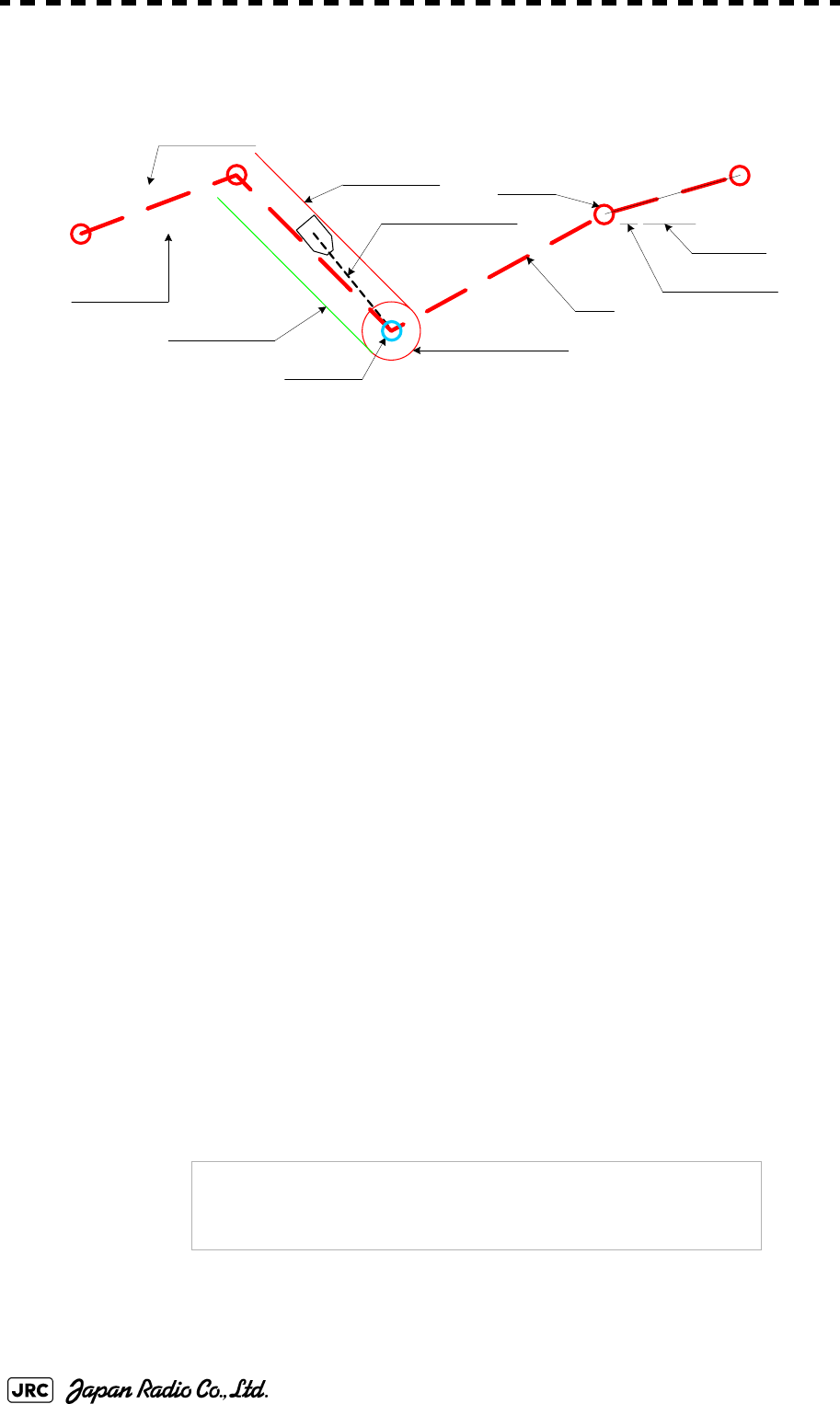
3-68
JMA-9100 Instruction Manual > 3.BASIC OPERATION > 3.7 USE ROUTE FUNCTION
3.7.1.1 Displaying route created by the radar system (Internal)
In this radar system, route created by the radar system are displayed as shown below.
The following rout data is displayed.
3.7.2 Edit Route (Set Route Sequence)
In this radar system, it is possible to easily create and correct route by performing
operation on the radar display.
3.7.2.1 Initializing route data (New Monitor Route)
Route data saved in the radar system is initialized.
Waypoint : Up to 512 points (number: 000 to 511), comments can be entered.
To Waypoint : Next Waypoint is displayed in a light blue circle.
Route : A route line that connects Waypoints.
Planned Courese : Scheduled route between Waypoints (automatically calculated).
Planned Speed : Scheduled sailing speed between Waypoints (entered by user).
Waypoint alarm circle : The circle that shows the distance to judge arrival in Waypoint.
Route alarm line : The line that shows the distance width to judge route alarm.
Waypoint bearing vector : A vector line that shows next destination from own ship's CCRP.
NOTE:
Once route data is initialized, route data saved in the
radar system's storage section is deleted. If there is
necessary route data, save the route data on the flash
memory card before initializing it.
000
ABCDE
001
002 FGJK
003 OPQRS
004
Waypoint
To Waypoint
Waypoint bearing vector
Waypoint alarm circle
Route
Waypoint number
Comments
Route alarm line
Route alarm line
070T
2.50kn
062T
074T
Planned Course
Planned Speed
135T
5.00kn
10.0kn
12.5kn

JMA-9100 Instruction Manual > 3.BASIC OPERATION > 3.7 USE ROUTE FUNCTION
3-69
3
Procedures
1) Open the Set Route Sequence menu by performing the menu
operation below.
→
→
2) Left-click the button.
Confirmation Window will appear.
3) Left-click the button.
The saved route data will be deleted.
3.7.2.2 Adding a Waypoint (Add Waypoint)
New Waypoint data is added to the route data saved in the radar system.
Procedures
1) Open the Set Route Sequence menu by performing the menu
operation below.
→
→
2) Left-click the button.
The Waypoint adding mode is selected.
The rubber band from the last Waypoint to the cursor position will be displayed on the radar
display.
3) Left-click the location at which you want to add a Waypoint.
A Waypoint will be added.
When a Waypoint is added, the value of the Planned Speed in the section up to the menu is
used for the Planned Speed value up to the added Waypoint.
Route
2. WPT/Route Setting
3. Set Route Sequence
7. New Monitor Route
1. Yes
Route
2. WPT/Route Setting
3. Set Route Sequence
2. Add
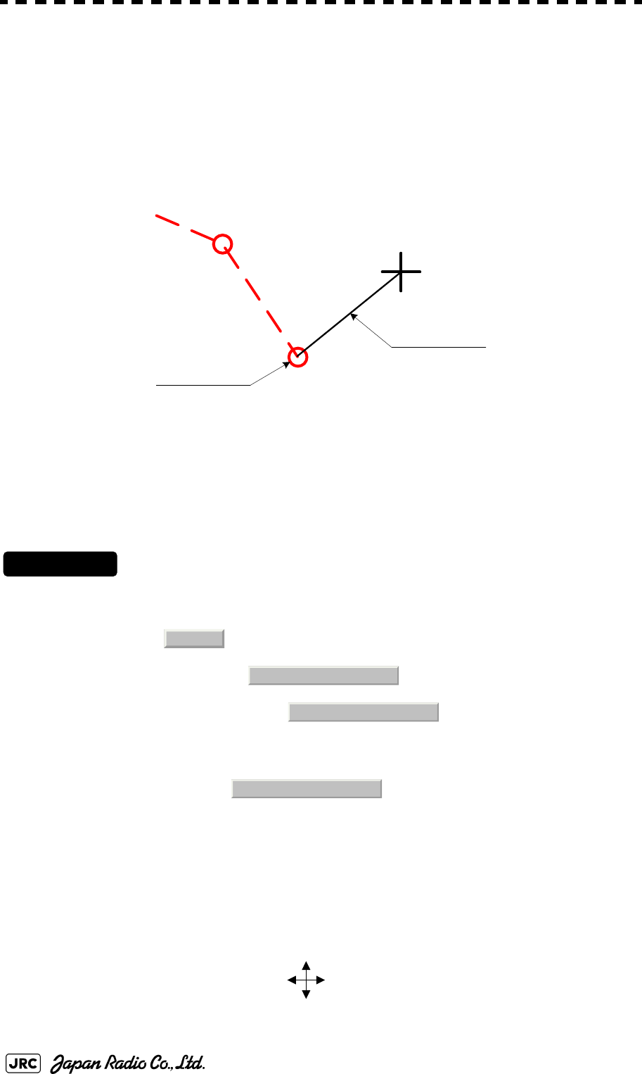
3-70
JMA-9100 Instruction Manual > 3.BASIC OPERATION > 3.7 USE ROUTE FUNCTION
4) To add another Waypoint, repeat procedure 3.
5) To finish adding a Waypoint, left-click twice at the last Waypoint.
The Waypoint adding mode is cancelled.
(Example)
3.7.2.3 Correcting coordinates of a Waypoint (Correct Position)
The coordinates of a Waypoint in the route data saved in the radar system are corrected.
Procedures
1) Open the Set Route Sequence menu by performing the menu
operation below.
→
→
2) Left-click the button.
The Waypoint correcting mode is selected.
3) On the radar display, put the cursor on the Waypoint that is to
have its coordinates corrected, and left-click.
The Waypoint to be corrected is specified.
The cursor display becomes a cursor mark, and a rubber band is displayed.
062T
12.0kn
Last Waypoint
Rubber ban
d
023
024
Route
2. WPT/Route Setting
3. Set Route Sequence
3. Correct Position
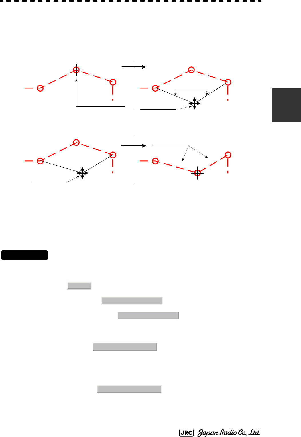
JMA-9100 Instruction Manual > 3.BASIC OPERATION > 3.7 USE ROUTE FUNCTION
3-71
3
4) Move the cursor to new coordinates, and left-click.
The coordinates of the Waypoint are corrected, and then the Waypoint correcting mode is
cancelled.
(Example)
3.7.2.4 Correcting Planned Speed (Correct Planned Speed)
Planned Speed of the route data saved in the radar system is corrected.
Procedures
1) Open the Set Route Sequence menu by performing the menu
operation below.
→
→
2) Left-click the button.
The Planned Speed correcting mode is selected.
3) Left-click the button.
The Planned Speed input screen will appear.
Enter a numeric value of new Planned Speed.
025
Waypoint that is to have its
position corrected
Rubber band
Cross cursor mark
Click at this position
064T
12.0kn 8.00kn
108T 064T 108T
064T 108T
106T 060T
Planned Course
024
025
026
024
025
026
026
024024
025
026
12.0kn 8.00kn
12.0kn 8.00kn
12.0kn 8. 00kn
Route
2. WPT/Route Setting
3. Set Route Sequence
4. Correct Planned Speed
1. Planned Speed
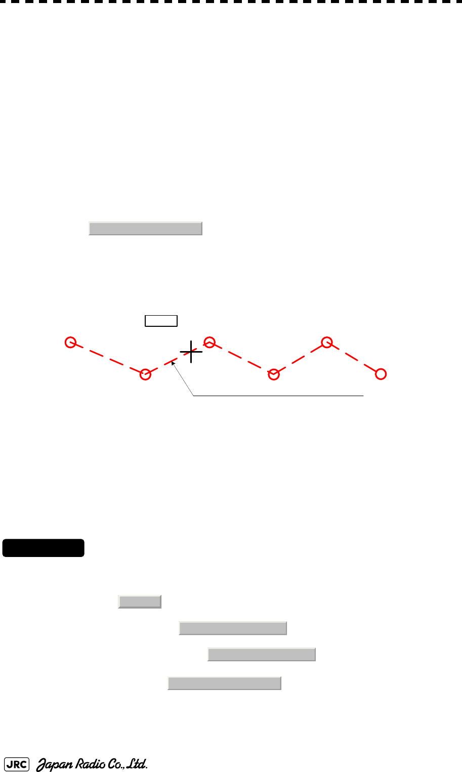
3-72
JMA-9100 Instruction Manual > 3.BASIC OPERATION > 3.7 USE ROUTE FUNCTION
4) On the radar display, put the cursor on the line extending
between Waypoints that is to have its Planned Speed corrected.
The section that is to have its Planned Speed corrected is specified, and the new Planned
Speed is applied to the section.
5) To correct the Planned Speed of another section, repeat
procedures 3 and 4.
6) To finish correcting Planned Speed, left-click the
button.
The Planned Speed correcting mode will be cancelled.
(Example)
3.7.2.5 Deleting a Waypoint (Delete Waypoint)
The specified Waypoint in the route data saved in the radar system is deleted.
Procedures
1) Open the Set Route Sequence menu by performing the menu
operation below.
→
→
2) Left-click the button.
The Waypoint deleting mode is selected.
4. Correct Planned Speed
000
001
002
003
004
005
064T
8.00kn 9.00kn 10.0kn 11.0kn 12.0kn
113T 113T 064T 113T
Planned speed:10.00kn
Section that is to have its Planned Speed corrected
Route
2. WPT/Route Setting
3. Set Route Sequence
5. Delete
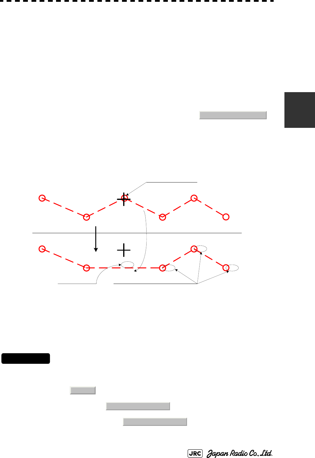
JMA-9100 Instruction Manual > 3.BASIC OPERATION > 3.7 USE ROUTE FUNCTION
3-73
3
3) On the radar display, put the cursor on a Waypoint to be deleted,
and left-click.
The specified Waypoint is deleted, and the previous and following Waypoints are then
connected by a line.
4) To delete another Waypoint, repeat procedure 3.
5) To finish deleting a Waypoint, left-click the
button.
The Waypoint deleting mode will be cancelled.
(Example)
3.7.2.6 Inserting a Waypoint (Insert Waypoint)
A Waypoint is inserted at a specific location of the route data saved in the radar system.
Procedures
1) Open the Set Route Sequence menu by performing the menu
operation below.
→
→
5. Delete
000
001
002
003
004
005
064T
113T 113T 064T 113T
Waypoints are re-numbered.
000
001 002
003
004
113T
090T
064T 113T
Left-click Planned speed
Waypoint to be deleted
Calculated again
8.00kn 10.0kn 11.0kn 12.0kn
9.00kn
8.00kn
10.0kn
11.0kn 12.0kn
Route
2. WPT/Route Setting
3. Set Route Sequence
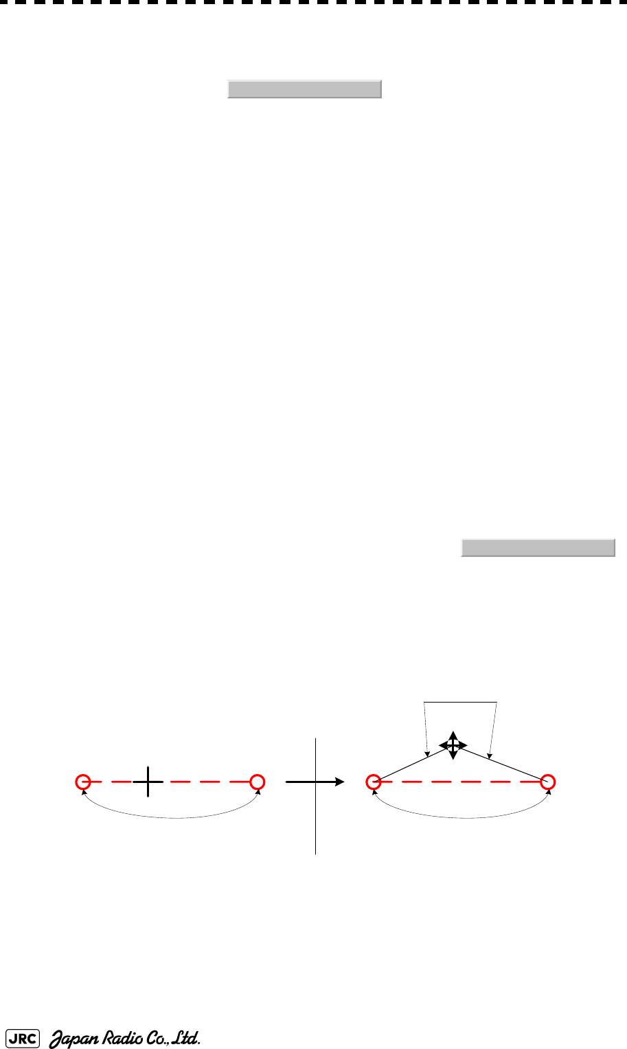
3-74
JMA-9100 Instruction Manual > 3.BASIC OPERATION > 3.7 USE ROUTE FUNCTION
2) Left-click the button.
The Waypoint inserting mode is selected.
3) On the radar display, put the cursor on the section line into
which a Waypoint is to be inserted, and left-click.
The section is specified, the cursor becomes a cross cursor mark, and the cross cursor mark is
connected to the previous and following Waypoints by a rubber band.
4) On the radar display, put the cursor on the location at which a
Waypoint is to be inserted, and left-click.
The coordinates of the new Waypoint are specified, and the new Waypoint is connected to
the previous and following Waypoints by a line.
5) To insert another Waypoint, repeat procedures 3 and 4.
6) To finish inserting a Waypoint, left-click the
button.
The Waypoint inserting mode will be cancelled.
(Example)
6. Insert
6. Insert
001 10.0kn
090T
Waypoint is inserted into this section.
001 090T
Waypoint is inserted into this section.
Rubber band
10.0kn
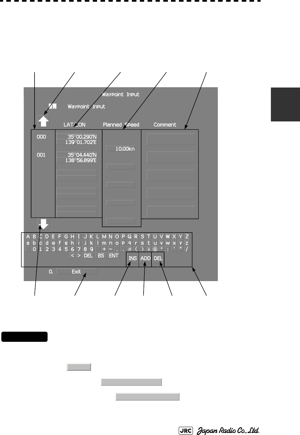
JMA-9100 Instruction Manual > 3.BASIC OPERATION > 3.7 USE ROUTE FUNCTION
3-75
3
3.7.3 Edit Route Make with Latitude and Longitude (Waypoint
Input)
In this radar system, it is possible to create and correct route by performing
operation on the Waipoint Input menu.
3.7.3.1 Open the Waipoint Input Menu
Procedures
1) Open the Waypoint Input menu by performing the menu
operation below.
→
→
When transmitting, it can not be open.
Waypoint Commen
t
Waypoint
Latitude/Longitude
Waypoint Number
Input CharacterExit
Planned SpeedWaypoint Scroll
Waypoint Scroll Waypoint
Insert
Waypoint
Addition
Waypoint
Delete
Route
2. WPT/Route Setting
6. Waypoint Input

3-76
JMA-9100 Instruction Manual > 3.BASIC OPERATION > 3.7 USE ROUTE FUNCTION
3.7.3.2 Adding a Waypoint (Add)
New Waypoint data is added to the route data saved in the radar system.
Procedures
1) Open the Waipoint Input menu.
2) Left-click the button.
The new latitude of waypoint is reversed.
3) Enter a latitude / longitude and a planned speed.
A Waypoint will be added.
For the input method on the latitude / longitude and numeric value input screen, see Section
3.3.4.5 "Entering latitude/longitude" and Section 3.3.4.7 "Entering a character".
3.7.3.3 Adding a Comment (Comment)
New Waypoint data is added to the route data saved in the radar system.
Procedures
1) Open the Waipoint Input menu.
2) Left-click the Waypoint Scroll button.
Left-click to show the desired comment.
3) Left-click the Comment button to be added.
The comment of waypoint is reversed.
4) Enter a comment.
A comment will be added.
For the input method on the character input screen, see Section 3.3.4.7 "Entering a
character".
ADD

JMA-9100 Instruction Manual > 3.BASIC OPERATION > 3.7 USE ROUTE FUNCTION
3-77
3
3.7.3.4 Correcting latitude / longitude of a Waypoint (LAT/LON)
The latitude / longitude of a Waypoint in the route data saved in the radar system are
corrected.
Procedures
1) Open the Waipoint Input menu.
2) Left-click the Waypoint Scroll button.
Left-click to show the desired latitude / longitude.
3) Left-click the Latitude / Longitude button to be corrected.
The latitude of waypoint is reversed.
4) Enter a latitude / longitude.
A Waypoint will be corrected.
For the input method on the latitude / longitude input screen, see Section 3.3.4.5 "Entering
latitude/longitude".
3.7.3.5 Correcting Planned Speed (Planned Speed)
Planned Speed of the route data saved in the radar system is corrected.
Procedures
1) Open the Waipoint Input menu.
2) Left-click the Waypoint Scroll button.
Left-click to show the desired planned speed.
3) Left-click the Planned Speed button to be corrected.
The planned speed of waypoint is reversed.
4) Enter a planned speed.
A Planned Speed will be corrected.
For the input method on the numeric value input screen, see Section 3.3.4 "Operation on
Numeric Value, Latitude / Longitude and Character Input menu".

3-78
JMA-9100 Instruction Manual > 3.BASIC OPERATION > 3.7 USE ROUTE FUNCTION
3.7.3.6 Deleting a Waypoint (DEL)
The specified Waypoint in the route data saved in the radar system is deleted.
Procedures
1) Open the Waipoint Input menu.
2) Left-click the Waypoint Scroll button.
Left-click to show the desired waypoint.
3) Left-click the button to be corrected.
Confirmation Window will appear.
4) Left-click the button.
The specified Waypoint is deleted, and the previous and following Waypoints are then
connected by a line.
3.7.3.7 Inserting a Waypoint (INS)
A Waypoint is inserted at a specific location of the route data saved in the radar system.
Procedures
1) Open the Waipoint Input menu.
2) Left-click the Waypoint Scroll button.
Left-click to show the desired waypoint.
3) Left-click the button to be corrected.
The new latitude of waypoint is reversed.
4) Enter a latitude / longitude and a planned speed.
A Waypoint will be inserted.
For the input method on the latitude / longitude and numeric value input screen, see Section
3.3.4 "Operation on Numeric Value, Latitude / Longitude and Character Input menu".
DEL
1. Yes
INS
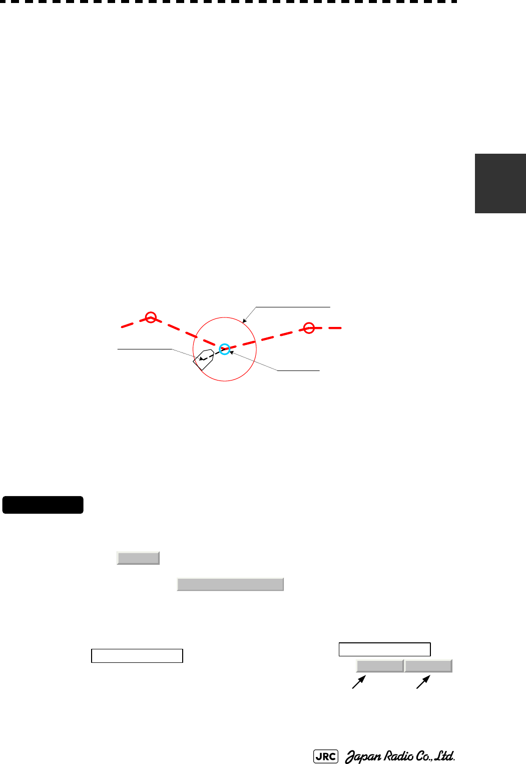
JMA-9100 Instruction Manual > 3.BASIC OPERATION > 3.7 USE ROUTE FUNCTION
3-79
3
3.7.4 Use Route Monitoring Function (Waypoint/Route Alarm)
This radar system can monitor the movement of own ship with regard to its route
and activate a variety of alarms.
3.7.4.1 Destination alarm (Waypoint Alarm)
The destination alarm is activated when own ship has reached next Waypoint or own ship
has deviated from the scheduled route.
A Waypoint alarm circle with a specified radius distance is displayed.
Waypoint Alarm has the following two types of alarms:
Procedures
1) Open the WPT/Route Setting menu by performing the menu
operation below.
→
2) Left-click the set value of the
item, and select
an operation mode.
Destination alarm
(Waypoint Alarm):
When own ship arrives at next Waypoint, an alarm will
be activated.
Route alarm: When own ship deviates from the specified route, an
alarm will be activated.
Arrival: An alarm is activated when own ship has entered the circle from outside.
Break Off: An alarm is activated when own ship has left the circle to the outside.
To Waypoint
Waypoint alarm circle
Own ship position
Route
2. WPT/Route Setting
Arrival 0.00nm
1. Waypoint Alarm
Operation mode
Radius of the
Waypoint alarm
circle
1. Waypoint Alarm
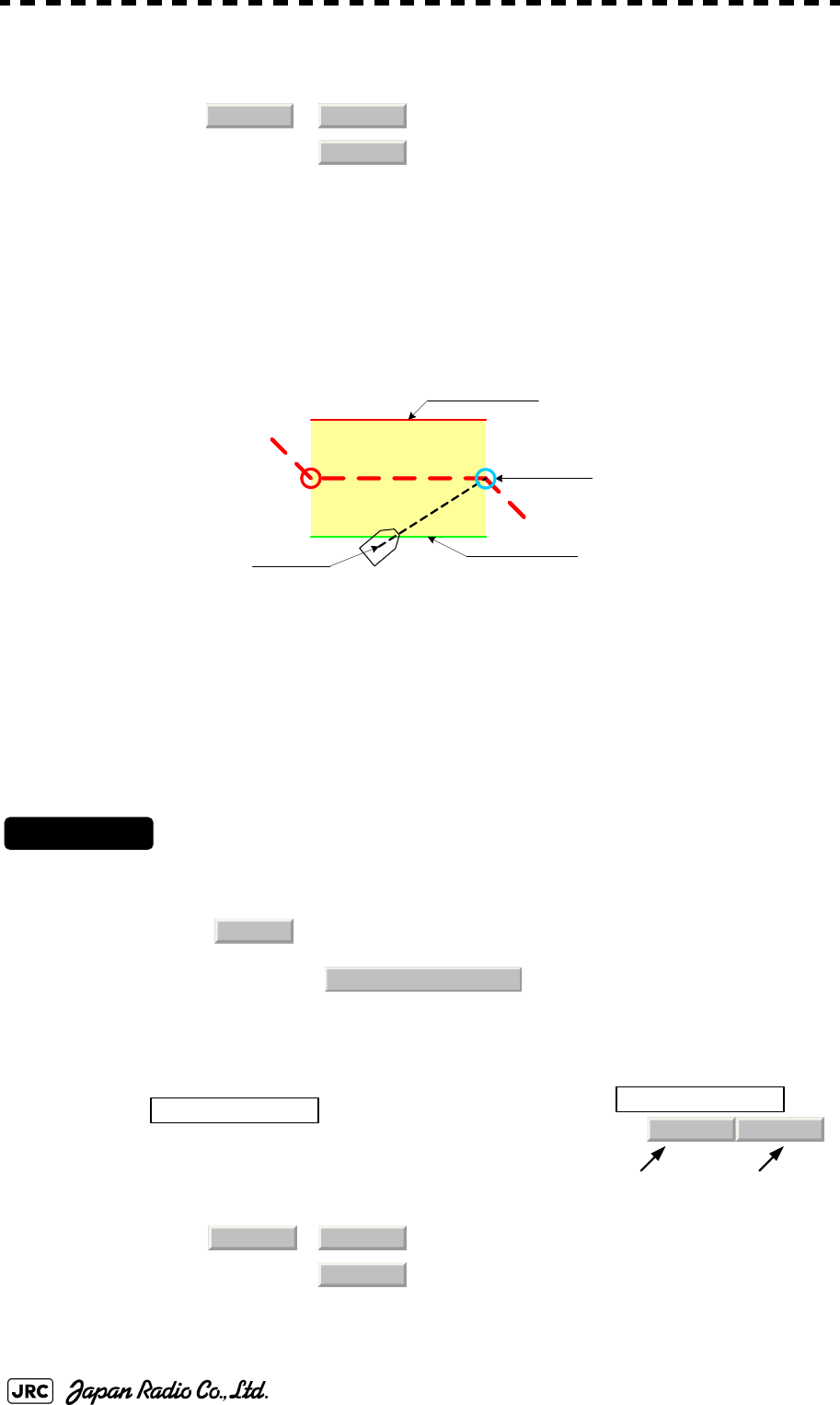
3-80
JMA-9100 Instruction Manual > 3.BASIC OPERATION > 3.7 USE ROUTE FUNCTION
3.7.4.2 Route Alarm
The route alarm is activated when own ship deviates from the specified width of the route.
The route alarm lines are displayed with a specified width provided.
Route Alarm has the following two types of operations:
Procedures
1) Open the WPT/Route Setting menu by performing the menu
operation below.
→
2) Left-click the set value of the
item, and select an
operation mode.
/ : Set the operation mode.
: Set the radius of the Waypoint alarm circle. If
0.00nm is set, alarm operation will be turned off.
Approach:An alarm is activated when own ship enters the route range from
outside.
XTE(Cross
Track Error):
An alarm is activated when own ship leaves the route range.
/ : Set the operation mode.
: Set the width of the route (one side). If
0.00nm is set, an alarm operation will be
turned off.
Arrival
Break Off
0.00nm
To Waypoint
Own ship
position Route alarm line
Route alarm line
Break Off alarm is activated
when own ship is outside the
specified range.
Route
2. WPT/Route Setting
Approach 0.00nm
2. Route Alarm
Operation mode
Width of the rout
e
(one side)
2. Route Alarm
Approach XTE
0.00nm
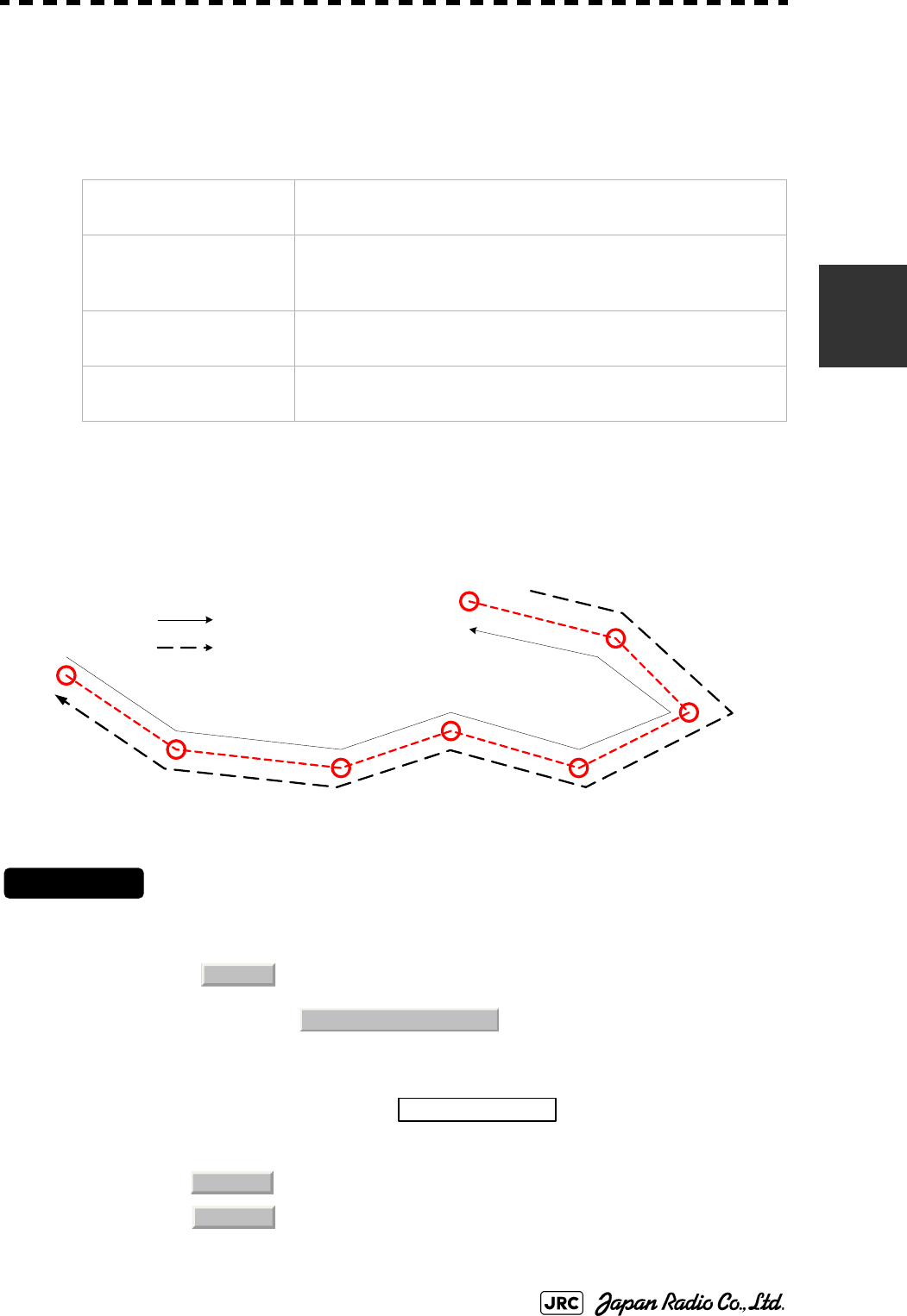
JMA-9100 Instruction Manual > 3.BASIC OPERATION > 3.7 USE ROUTE FUNCTION
3-81
3
3.7.5 Method of Using Route
The method of using the route will be described.
3.7.5.1 Selecting the forward or backward of the route (Route Sequence)
Select whether Waypoints in route data are used in the forward direction or
backward direction.
Procedures
1) Open the WPT/Route Operations menu by performing the menu
operation below.
→
2 Left-click the set value of the item, and select an
operation mode.
Displaying the route
(Route Alarm Color):
The internal route is displayed according to the procedures in
Section 3.7.1 "Display Route/Destination Mark (Select Route)".
Selecting the forward or
backward of the route
(Route Sequence):
Whether to use Waypoints forward or backward is selected.
Skipping of route
(Waypoint Skip):
The Waypoint which is after next Waypoint is set as the next
Waypoint.
Skipping back of the route
(Waypoint Back Skip):
The previous Waypoint is set as the next Waypoint.
:Waypoints are used in the forward direction (ascending order).
:Waypoints are used in the reverse direction (descending order).
001
002
003
004
005
006
007
000
: Forward
: Backward
Route
3. WPT/Route Operations
1. Route Sequence
Forward
Reverse
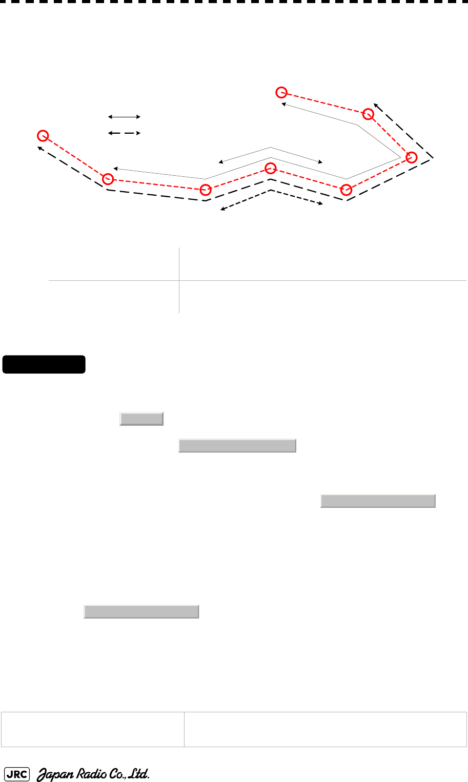
3-82
JMA-9100 Instruction Manual > 3.BASIC OPERATION > 3.7 USE ROUTE FUNCTION
3.7.5.2 Skipping/Back-skipping of the route (Waypoint Skip/ Waypoint Back
Skip)
Next Waypoint of the route can be changed by user manually.
Procedures
1) Open the WPT/Route Operations menu by performing the menu
operation below.
→
2) To execute Waypoint Skip, left-click the
button.
The Waypoint which is after the next Waypoint is set as the next Waypoint.
3) To execute Waypoint Back Skip, left-click the
Skip button.
The previous Waypoint is set as the next Waypoint.
3.7.6 Detailed Route Settings
Make detailed settings of the route.
Skipping of route
(Waypoint Skip):
The Waypoint which is after the next Waypoint is set as the
next Waypoint.
Skipping back the route
(Waypoint Back Skip):
The previous Waypoint is set as the next Waypoint.
Color for the route alarm line
(SEL NUM/Comment Size)
Set the display color for the route alarm line.
001
002
003
004
005
006
007
000
: Forward
:Backward
Waypoint Skip
Waypoint Back Skip
Waypoint Skip
Waypoint Back Skip
Route
3. WPT/Route Operations
3. Waypoint Skip
4. Waypoint Back Skip
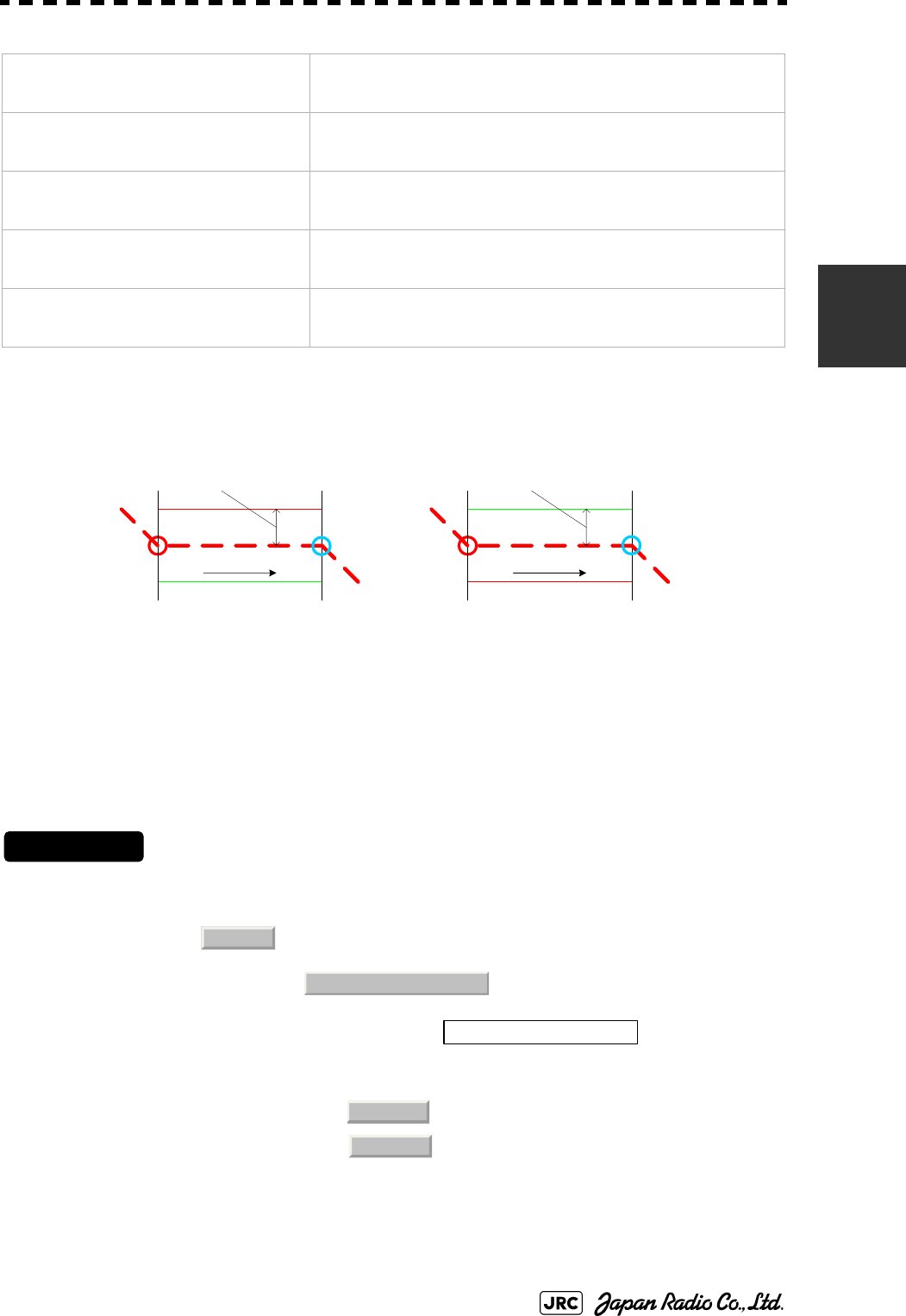
JMA-9100 Instruction Manual > 3.BASIC OPERATION > 3.7 USE ROUTE FUNCTION
3-83
3
3.7.6.1 Color for the route alarm line (Off-Track Limit Line)
Route alarm lines are displayed on both sides of the center line of the route.
For this item, set which color is used to display each line.
Procedures
1) Open the WPT/Route Setting menu by performing the menu
operation below.
→
2) Left-click the set value of the item, and
select an operation mode.
3.7.6.2 Display character size (SEL NUM/Comment Size)
Specify the size of the numeric value and character displayed on the radar display.
Display character size
(SEL NUM/Comment Size)
:Specify the size of the numeric value and character displayed on
the radar display.
Waypoint bearing vector
(Waypoint Vector)
:Set the method to display line between next Waypoint and own
ship.
Display of bearing distance to the
destination(Status of Origin/DEST)
:Select the start point to be used for the bearing/distance display in
the Waypoint data display area.
ON/OFF of Waypoint number display
(WPT Number Display)
:Set whether or not to display Waypoint number next to the
Waypoint mark.
Waypoint update
(Waypoint Switch Mode)
:Set how to update Waypoint number when one Waypoint has been
reached.
Area A (IALA-A):The port-side is red and the bow-side is green
along the traveling direction.
Area B (IALA-B):The port-side is green and the bow-side is red
along the traveling direction.
: Area A
: Area B
Route alarm lineRoute alarm line
Traveli ng dir ecti on Tr aveli ng dir ection
Route Alarm Color: Area A Route Alarm Color: Area B
Route
2. WPT/Route Setting
8. Off-Track Limit Line
IALA-A
IALA-B
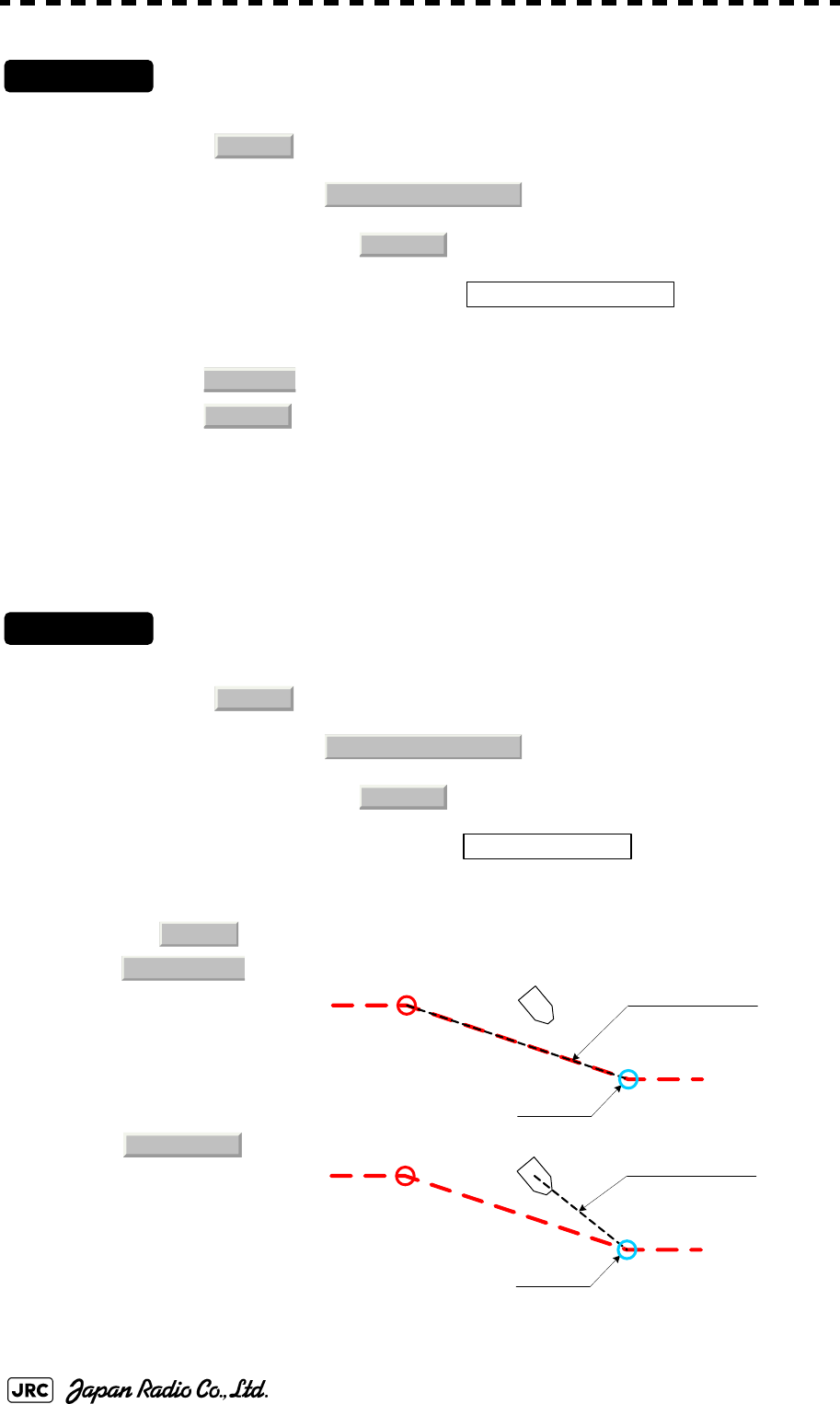
3-84
JMA-9100 Instruction Manual > 3.BASIC OPERATION > 3.7 USE ROUTE FUNCTION
Procedures
1) Open the Next menu by performing the menu operation below.
→
→
2) Left-click the set value of the item, and
select an operation mode.
3.7.6.3 Waypoint bearing vector (Waypoint Vector)
Set how to display a line between next Waypoint and own ship.
Procedures
1) Open the Next menu by performing the menu operation below.
→
→
2) Left-click the set value of the item, and select
an operation mode.
:Numbers and characters are displayed in normal size.
:Numbers and characters are displayed in a size smaller than
usual.
: The Waypoint bearing vector is not displayed.
: A line is displayed from the previous Waypoint to next Waypoint.
: A line is displayed from own ship to next Waypoint.
Route
2. WPT/Route Setting
9. Next
1. SEL NUM/Comment Size
Normal
Small
Route
2. WPT/Route Setting
9. Next
2. Waypoint Vector
Off
From Origin
Waypoint bearing vecto
r
To Waypoint
From CURR
To Waypoint
Waypoint bearing vecto
r
JMA-9100 Instruction Manual > 3.BASIC OPERATION > 3.7 USE ROUTE FUNCTION
3-85
3
3.7.6.4 Displaying bearing distance to the Waypoint (Status of Origin/DEST)
Select a start point used to display bearing/distance in the Waypoint data display area.
Procedures
1) Open the Next menu by performing the menu operation below.
→
→
2) Left-click the set value of the item, and
select an operation mode.
3.7.6.5 ON/OFF of Waypoint number display (WPT Number Display)
Set whether to display a Waypoint number next to the Waypoint mark.
Procedures
1) Open the Next menu by performing the menu operation below.
→
→
2) Left-click the set value of the item, and
select an operation mode.
:The bearing distance from the own ship position
to next Waypoint is displayed.
:The bearing distance from the previous Waypoint
to next Waypoint is displayed.
: The Waypoint number is not displayed.
: The Waypoint number is displayed.
Route
2. WPT/Route Setting
9. Next
3. Status of Origin/DEST
From CURR POSN
Fix
Route
2. WPT/Route Setting
9. Next
4. WPT Number Display
Off
On
3-86
JMA-9100 Instruction Manual > 3.BASIC OPERATION > 3.7 USE ROUTE FUNCTION
3.7.6.6 Updating Waypoint data (Waypoint Switch Mode)
Set how to update the Waypoint number when one Waypoint has been reached.
Procedures
1) Open the WPT/Route Operations menu by performing the menu
operation below.
→
2) Left-click the set value of the item, and
select an operation mode.
3.7.7 Clear Waypoint/Route Data (Clear WPT/Route Data)
This function clears waypoint/route data from memory.
Procedures
1) Open the WPT/Route Operations menu by performing the menu
operation below.
→
2) Left-click the button.
Confirmation Window will appear.
3) Left-click the button.
A route data will be cleared.
: When next Waypoint has been reached, user updates the
following Waypoint.
: When next Waypoint has been reached, the following
Waypoint is automatically updated.
NOTE:
If data is not copied on the flash memory card (option),
the data is not be reloaded.
Route
3. WPT/Route Operations
2. Waypoint Switch Mode
Manual
AUTO
Route
3. WPT/Route Operations
6. Clear WPT/Route Data
1. Yes
JMA-9100 Instruction Manual > 3.BASIC OPERATION > 3.7 USE ROUTE FUNCTION
3-87
3
3.7.8 Operate Route Data File
Route data saved in the radar system can be saved onto a flash memory card, and
data can be loaded from a flash memory card into the radar system.
With regard to this item, only route data can be saved and loaded. To save or load
own ship's track, target track data, and mark/line data, see Section 3.11 "USING
CARD".
3.7.8.1 Selecting a card slot (Select Card Slot)
Specify the card slot to be used for accessing a route data file
Flash memory card (option) is necessary.
Procedures
1) Insert a flash memory card into the card slot.
2) Open the File Operations menu by performing the menu
operation below.
→
3) Left-click the set value of the item, and
select a card slot.
Slot1 and Slot2 of the Select Card Slot items are switched.
3.7.8.2 Saving route data (Save)
Route data saved in the radar system is saved onto a flash memory card.
Flash memory card (option) is necessary.
Selecting a card slot
(Select Card Slot):
Specify the card slot to be used for operating a
route data file.
Saving route data (Save): Route data saved in the radar system is saved
onto a flash memory card.
Loading route data (Load): Route data saved on a flash memory card is
loaded into the radar system.
Erasing route data file
(Erase):
A route data file saved in a flash memory card
is erased.
Route
4. File Operation
1. Select Card Slot

3-88
JMA-9100 Instruction Manual > 3.BASIC OPERATION > 3.7 USE ROUTE FUNCTION
Procedures
1) Insert a flash memory card into the card slot.
2) Open the File Operations menu by performing the menu
operation below.
→
3) Left-click the button.
The file name input screen will appear.
For the input method on the character input screen, see Section 3.3.4.7 "Entering a
character".
4) After having entered a file name, left-click the button.
The entry of the file name will be finished.
Confirmation Window will appear.
5) Left-click the button.
The route data will be saved with the specified file name.
3.7.8.3 Loading route data (Load)
Route data is loaded into the radar system from a flash memory card.
Flash memory card (option) is necessary.
NOTE:
Once route data has been loaded into the radar system from a
flash memory card, the route data that has been saved in the
radar system is overwritten and erased. Route data that has
been erased cannot be resaved. Note that important route data
should be saved in a flash memory card.
Route
4. File Operation
3. Save
ENT
1. Yes

JMA-9100 Instruction Manual > 3.BASIC OPERATION > 3.7 USE ROUTE FUNCTION
3-89
3
Procedures
1) Insert a flash memory card into the card slot.
2) Open the File Operations menu by performing the menu
operation below.
→
3) Left-click the button.
Contents of the specified memory card (file list) will be displayed.
4) Left-click the button for the desired file name.
Confirmation Window will appear.
5) Left-click the button.
The route data with the specified file name will be loaded.
3.7.8.4 Erasing route data (Erase)
An unnecessary route data file saved on a flash memory card is erased.
Flash memory card (option) is necessary.
Procedures
1) Insert a flash memory card into the card slot.
2) Open the File Operations menu by performing the menu
operation below.
→
NOTE:
Once route data files that have been saved on a flash
memory card is erased, the erased data cannot be
resaved. Note that important files should not be erased.
Route
4. File Operation
2. Load
1. Yes
Route
4. File Operation

3-90
JMA-9100 Instruction Manual > 3.BASIC OPERATION > 3.7 USE ROUTE FUNCTION
3) Left-click the button.
Contents of the specified memory card (file list) will be displayed.
4) Left-click the button for the desired file name.
Confirmation Window will appear.
5) Left-click the button.
A route data file with the specified file name will be erased.
4. Erase
1. Yes

JMA-9100 Instruction Manual > 3.BASIC OPERATION > 3.8 APPLIED OPERATIONS
3-91
3
3.8 APPLIED OPERATIONS
3.8.1 Set Radar Signal Processing (Process Setting)
This function enables the setting of detail information about radar signal
processing.
Procedures
1) Open the Process Setting menu by performing the menu
operation below.
→
→
The Process Setting menu will appear.
Detail information about radar signal processing can be set by changing the settings of the
menu items.
3.8.1.1 Video Latitude
•Select the dynamic range in which receiving signals are to be shown on the
radar display.
•Select in standard, and in rainy weather.
• clearly displays short-range videos when STC is used in manual
mode.
NOTE:
After the settings for radar signal processing are
changed, small targets may not be displayed or
unwanted waves may not be suppressed. Thus, do not
make a significant change in the settings.
: Narrows the dynamic range at short range.
: Standard setting
The dynamic range varies depending on the actual range:
Short distance: wide Long distance: narrow
: Use this mode when rainy weather intensifies unwanted
waves.The dynamic range is about twice as wide as when
is selected.
: Use this mode when rain cloud remain at mode.
Main
3. RADAR Menu
1. Process Setting
Normal Wide
Narrow
Narrow
Normal
Wide
Normal
Super Wide Wide

3-92
JMA-9100 Instruction Manual > 3.BASIC OPERATION > 3.8 APPLIED OPERATIONS
3.8.1.2 Video Noise Rejection
•This function rejects signals that assumed as noise and clutter in radar videos.
•Select to display radar videos like analog signals.
•Select or to suppress noise and clutter.
•Select or to superimpose-display the chart.
3.8.1.3 Auto Dynamic Range
•When the automatic sea clutter suppression mode and the automatic rain/snow
clutter suppression mode are in use, the dynamic range is automatically
controlled.
•When the automatic sea clutter suppression mode is in use, this function
improves gain by widening the dynamic range of only areas where sea clutter
is strong and narrowing the dynamic range of areas where sea clutter is not
detected.
•When the automatic rain/snow clutter suppression mode is in use, this function
improves gain by widening the dynamic range of areas where sea clutter and
rain/snow clutter are strong and narrowing the dynamic range of the other
areas.
•Land videos become obscure when the automatic rain/snow clutter suppression
mode is in use.
:Turns off the noise rejection function, and displays all
signals. Targets are popped up from noise and displayed
like analog signals.
:Rejects the signals of definitely unwanted waves (noise and
clutter). When detection of targets or unwanted waves is not
definite, the signals are displayed.
:Rejects the signals of definitely unwanted waves (noise and
clutter). When detection of targets or unwanted waves is not
definite, the signals are rejected. Only when detection of
targets is definite, the signals are displayed.
:Does not control the dynamic range automatically.
(Standard setting) The dynamic range is set in the same
manner as when the manual sea clutter suppression mode
or the manual rain/snow clutter suppression mode is in use.
:Automatically controls the dynamic range.
Off
Level1 Level2
Level1 Level2
Off
Level1
Level2
Off
On

JMA-9100 Instruction Manual > 3.BASIC OPERATION > 3.8 APPLIED OPERATIONS
3-93
3
3.8.1.4 Process Switch
•This function sets a specific area and switches the video process mode between
the inside and outside of the area.
•In Section 3.8.1.5 "2nd Porcess Mode" 2nd Process Mode, set the second video
process mode for the area outside the boundary.
•In [2] PROCESS of Main Menu , set the first video process mode for the area
inside the boundary.
•Gain at a distance can be improved by suppressing near sea clutter through the
correlative process.
•There are two methods for setting an area:
3.8.1.5 2nd Porcess Mode
•Set the second video process mode for the outside of a specific area.
•This function is enabled when or is selected in Section
3.8.1.4 "Process Switch".
3.8.1.6 Process Switch Range
•Set the boundary range of a specific area.
•This function is enabled when is selected in Section 3.8.1.4
"Process Switch".
•The specific area turns out to be a circle with the own ship’s position as the
center.
•The boundary range can be set in units of 0.1 nm, ranging 0.1 to 25.5 nm.
:Disables the Process Switching function. (Standard
setting)
:Sets a boundary at a constant range from the center. Set
the boundary range in Section 3.8.1.6 "Process Switch
Range". The specific area turns out to be a circle with the
own ship’s position as the center.
:Automatically sets a specific area. The area subject to
many clutter returns is inside the boundary, and the area
less subject to clutter returns is outside the boundary.
Video process modes
: Select this mode in general.
: Select this mode when many rain/snow clutter returns are detected.
: Select this mode to highlight targets while suppressing sea clutter returns.
: Select this mode to detect small targets hidden by sea clutter returns.
: Select this mode when own ship yaws wildly.
: Select this mode to detect small targets of which detection probability is low.
Off
Range Fix
AUTO
Range Fix
AUTO
PROC Off
3Scan CORREL
4Scan CORREL
5Scan CORREL
Remain
Peak Hold
Range Fix

3-94
JMA-9100 Instruction Manual > 3.BASIC OPERATION > 3.8 APPLIED OPERATIONS
3.8.1.7 Fast Target Detection
•This function displays fast moving targets that are suppressed in scan-
correlative process mode.
•This function is enabled when , , or
is selected as the video process mode.
•If unwanted waves remain on the radar display, suppress them by using the
[SEA], [RAIN], or [GAIN] dial, or adjusting the interference rejection mode.
: Disables the Fast Target Detection function.
: Enables the Fast Target Detection function.
3Scan CORREL 4Scan CORREL
5Scan CORREL
Off
On

JMA-9100 Instruction Manual > 3.BASIC OPERATION > 3.8 APPLIED OPERATIONS
3-95
3
3.8.2 Set Radar Trails (RADAR Trails Setting)
This function enables the setting of detail information about radar trails
processing.
Procedures
1) Open the RADAR Trails Setting menu by performing the menu
operation below.
→
→
The RADAR Trails Setting menu will appear.
Detail data about radar trails processing can be set by changing the settings of each menu
item.
3.8.2.1 Trails Mode
•Set the radar trail display mode.
•For details on the trail mode, see Section 3.4.8 "Display Radar Trails (Trails)"
3.8.2.2 Trails REF Level
•Select a radar video level required for plotting radar trails.
•The radar video threshold level increases in order of →
→ → .
•To plot radar trails with unwanted waves, change to a higher level.
•To thin radar trails, change to a higher level.
•If radar trails are plotted in snatches, change to a lower level.
NOTE:
After the settings for radar trails processing are changed,
targets’ trails may not be displayed or trails may be plotted with
unwanted waves. Thus, do not make a significant change in the
settings.
Main
3. RADAR Menu
2. RADAR Trails Setting
Level1 Level2
Level3 Level4

3-96
JMA-9100 Instruction Manual > 3.BASIC OPERATION > 3.8 APPLIED OPERATIONS
3.8.2.3 Trails Reduction
•Make a setting for thinning radar trails.
•The effect of thinning increases in order of → →
.
•Radar videos do not become obscure because of the thinning of radar trails.
3.8.2.4 Trails Process
•Determine whether to use the video process with radar signals for plotting
radar trails.
•When Trails Process is , radar trails are never plotted with unwanted
waves, but the radar trails of moving targets may not be plotted.
•When Trails Process is , radar trails may be plotted with unwanted
waves, but the radar trails of moving targets are always plotted.
3.8.2.5 MAX Interval
•Select the maximum time for displaying radar trails.
•Select when short radar trails are often used in bays and the likes.
•Select when long radar trails are necessary for ocean navigation.
: Disables the Trails Reduction function.
: Enables the Trails Reduction function. (Effect: Low)
: Enables the Trails Reduction function. (Effect: Modest)
: Enables the Trails Reduction function. (Effect: High)
: Disables the Trails Process function.
: Enables the Trails Process function.
: Sets 15 minutes as the maximum time for radar trails display.
: Sets 30 minutes as the maximum time for radar trails display.
: Sets 60 minutes as the maximum time for radar trails display.
Level1 Level2
Level3
Off
Level1
Level2
Level3
On
Off
Off
On
Short
Long
Short
Middle
Long

JMA-9100 Instruction Manual > 3.BASIC OPERATION > 3.8 APPLIED OPERATIONS
3-97
3
3.8.3 Set Scanner Unit (TXRX Setting)
This function enables the setting of detail information about an antenna.
Procedures
1) Open the TXRX Setting menu by performing the menu operation
below.
→
→
The TXRX Setting menu will appear.
Detail information about antenna operation can be set by changing the settings of the menu
items.
3.8.3.1 PRF Fine Tuning
•Fine-tune the transmitting repetition frequency of the transmitter in the range
90 to 100%.
•If radar’s interference patterns are concentrically displayed, increment or
decrement the set value by 3 to 4 in order to heighten the effect of interference
rejection.
•One of 32 levels 0-31 can be set.
3.8.3.2 Stagger Trigger
•The interference reduction function is activated by using the transmission
repetition frequency control of the transmitter.
•This function is effective when radar interference does not go away.
3.8.3.3 PRF
•Select the operation mode the transmitting repetition frequency of the
transmitter.
: Stagger Trigger is not used.
: Stagger Trigger is used.
:Standard mode Both appropriate gain and magnetron's life
expectancy are maintained.
:Power saving mode Gain slightly lowers, but the service life of
magnetron is prolonged when short pulses
are used.
:High gain mode Gain improves when long pulses are used,
but the service life of magnetron is slightly
shortened.
Main
3. RADAR Menu
3. TXRX Setting
Off
On
Normal
Economy
High Power

3-98
JMA-9100 Instruction Manual > 3.BASIC OPERATION > 3.8 APPLIED OPERATIONS
3.8.3.4 Ice Class Standby Mode
•In this mode, the antenna is rotated when transmission is in the standby state.
•This mode is effective to prevent the antenna's rotating shaft from freezing.
3.8.4 Set Cursor (Cursor Setting)
This function enables the setting of detail information about cursor operation and
display.
Procedures
1) Open the Cursor Setting menu by performing the menu operation
below.
→
→
→
The Cursor Setting menu will appear.
Detail information about cursor operation and display can be set by changing the settings of
the menu items.
3.8.4.1 EBL/VRM Control CURS
•The EBL/VRM Control Cursor is switched between Valid and Invalid.
•The trackball is provided as a standard device. If the trackball malfunctions, the
cursor can be moved by using the [EBL] dial and [VRM] dial.
•The cursor moves horizontally when [EBL] is operated, and moves vertically
when [VRM] is operated.
•To switch between EBL/VRM operation and cursor operation while ON is
selected, hold down the [EBL] dial for 2 seconds.
:The ice class standby mode is not used. When transmission is
in the standby state, the antenna also stops rotating.
:The ice class standby mode is used. When transmission is in
the standby state, the antenna rotates.
: Cursor is operated using a [EBL] [VRM] dial.
: Cursor is operated using a trackball.
Off
On
Main
7. Sub Menu
9. EBL/Cursor Setting
3. Cursor Setting
On
Off

JMA-9100 Instruction Manual > 3.BASIC OPERATION > 3.8 APPLIED OPERATIONS
3-99
3
3.8.4.2 Cursor Length
•Set the length of the cross cursor mark on the radar display.
3.8.4.3 Cursor Pattern
•The type of the cross cursor mark displayed of the display is selected.
3.8.5 Set Radar Display (Display Setting)
This system can save combinations of display color and brilliance in accordance
with ambient lighting conditions and the radar display can be easily switched.
Follow the procedures below to set display color and brilliance to be saved before
hand.
3.8.5.1 Setting display color (Display Color Setting)
Procedures
1) Open the Color Setting menu by performing the menu operation
below.
→
→
Display Color Setting menu will appear.
Cuts the cross cursor mark in length.
: Makes the cross cursor mark twice as long as when
Short is selected.
: Type 1 is selected for the cross cursor mark 1 displayed in the radar display.
: Type 2 is selected for the cross cursor mark 2 displayed in the radar display.
: Type 3 is selected for the cross cursor mark 3 displayed in the radar display.
: Type 4 is selected for the cross cursor mark 4 displayed in the radar display.
Short
Long
Main
7. Sub Menu
1. Display Color Setting
3-100
JMA-9100 Instruction Manual > 3.BASIC OPERATION > 3.8 APPLIED OPERATIONS
3.8.5.2 Day/Night
•Specify the mode to be changed.
•The following modes are available:
Setting color of each element
•Specify the color for the element.
•The color for the following elements can be specified.
3.8.5.3 Setting display brilliance (Brilliance Setting)
For each Day/Night mode, background color outside the bearing scale,
background color inside the bearing scale, and color for characters, radar echo and
radar trails can be selected.
: Day mode 1 : Used under bright lighting conditions.
: Day mode 2 : Used under bright lighting conditions.
: Day mode 3 : Used under bright lighting conditions.
: Dusk mode : Used under dim lighting conditions.
: Night mode : Used under dark lighting conditions.
: The color of the background outside radar video PPI is
selected.
: The color of the background inside radar video PPI is
selected.
: The color of the character and bearing scale is selected.
: The color of the radar video is selected.
: The color of the time radar trails is selected.
: The color of the time radar trails is selected.
: The color of the target symbol is selected.
: The color of the cursor is selected.
: The color of the range rings is selected.
: The color of the EBL / VRM / PI is selected.
: The color of the own ship symbol, heading line, own
ship vector is selected.
i
Those selected color can be saved for each Day/Night mode.
Day1
Day2
Day3
Dusk
Night
Outer PPI
Inner PPI
Character
RADAR Video
RADAR Trails(Time)
RADAR Trails(All)
Target Symbol
Cursor
Range Rings
EBL/VRM/PI
Own Symbol /HL/Vector
JMA-9100 Instruction Manual > 3.BASIC OPERATION > 3.8 APPLIED OPERATIONS
3-101
3
Procedures
1) Open the Brilliance Setting menu by performing the menu
operation below.
→
→
Display Brilliance Setting menu will appear.
Setting brilliance of each element
•Specify the brilliance for the element.
•Level4 indicates maximum brilliance and Level1 indicates minimum brilliance.
•The brilliance for the following elements can be specified.
3.8.5.4 Setting radar video brilliance (VID)
The brilliance of the video on the radar display is adjusted.
Procedures
1) Left-click the button located at the lower right of the
radar display, and adjust the brilliance of the radar video so as to
get the best view of the video display.
The brilliance of the radar video can be adjusted on four stages without opening the
Brilliance Setting menu.
Adjust the radar display to obtain the best-to-view video.
: The brilliance of the radar video is selected.
: The brilliance of the radar trails is selected.
: The brilliance of the target symbol is selected.
: The brilliance of the range rings is selected.
: The brilliance of the EBL / VRM / PI is selected.
: The brilliance of the character and bearing scale is
selected.
: The brilliance of the own ship symbol, heading line, and
own ship vector is selected.
: The brilliance of the operation panel is selected.
i
Those selected brilliance can be saved for each Day/Night mode.
Main
7. Sub Menu
2. Brilliance Setting
RADAR Video
RADAR Trails
Target Symbol
Range Rings
EBL/VRM/PI
Character
Own Symbol /HL/Vector
Keyboard
VID
○
3-102
JMA-9100 Instruction Manual > 3.BASIC OPERATION > 3.8 APPLIED OPERATIONS
3.8.5.5 Setting target symbol brilliance (TT)
The brilliance of the target symbol on the radar display is adjusted.
Procedures
1) Left-click the button located at the lower right of the
radar display, and adjust the brilliance of the target symbol so as
to get the best view of the video display.
The brilliance of the target symbol can be adjusted on four stages without opening the
Brilliance Setting menu.
Adjust the radar display to obtain the best-to-view video.
3.8.6 Adjust Sound Volume (Buzzer Volume)
When an alarm is activated, the operation panel issues an alarm audible to inform
user of the change of the condition.
The alarm sound can be adjusted by performing the following procedures.
Procedures
1) Open the Buzzer Volume menu by performing the menu
operation below.
→
→
Display Buzzer Volume menu will appear.
The volume of the alarm sound can be specified for each cause for alarm.
indicates maximum volume and indicates minimum volume.
: The operation key acknowledgement is set.
: The incorrect operation alarm is set.
: The dangerous ship alarm is set.
: The automatic acquisition target alarm is set.
: The target lost alarm is set.
: The navigation data abnormality alarm is set.
: The system abnormality alarm is set.
: The inter switch switching alarm is set.
TT
○
Main
7. Sub Menu
2. Brilliance Setting
Level4 Level1
Key ACK
OPE Miss
CPA/TCPA Alarm
New Target Alarm
Lost Alarm
Navigation Alarm
System Alarm
Inter Switch

JMA-9100 Instruction Manual > 3.BASIC OPERATION > 3.8 APPLIED OPERATIONS
3-103
3
3.8.7 Set User Option Keys [OPTION 1/2]
Users can freely make settings with [OPTION 1] key and [OPTION 2] key.
By using the keys, users can open a frequently used menu by only single
operation, or assign special functions, to the user key switches.
3.8.7.1 Initial Setting (Option Key Setting)
Set functions that can be performed with the option key switches.
Procedures
1) Open the Option Key Setting menu by performing the menu
operation below.
→
→
The Option Key Setting menu will appear.
This system provides two user keys: [OPTION 1] and [OPTION 2]. Different functions can
be allocated to each key.
Functions that can be allocated to each key are as follows:
: A specific menu is directly displayed.
: The zoom display function is switched between on and off.
: Set/Cancel Waypoint menu key
: Start-point, Pass-point key in simple route operating
: End-point key in simple route operating
: Screen capture key (This function is enabled only when the
card (optional) is connected.)
Main
7. Sub Menu
4. Option Key Setting
Menu
Zoom
DEST
->○
○->
Capture Screen

3-104
JMA-9100 Instruction Manual > 3.BASIC OPERATION > 3.8 APPLIED OPERATIONS
3.8.7.2 Using Option Keys (Directly displaying a specified )
Preset the that is to be displayed with the option key switch.
Procedures
1) Perform the general menu open procedure to open the menu that
is to be directly displayed with Option Key.
2) While the menu is open, hold down [OPTION 1] key or [OPTION 2]
key for 2 seconds.
The menu currently being displayed is saved for the pressed option key.
3.8.7.3 How to use the Optin key ( Display)
Preset whether to execute the display by operating the user key.
Procedures
1) Press either [OPTION 1] key or [OPTION 2] key for which
has been set.
The zoom mode is activated.
2) Put the cursor on a location that is to be zoomed, and left-click.
Zoom is set.
Cancel
1) Press either [OPTION 1] key or [OPTION 2] key for which
has been set.
The zoom mode is cancelled and a normal display will appear.
i
The menu set for the pressed option key will open.
Subsequently, general menu operation can be performed.
Menu
Menu
Zoom
Zoom
Zoom
Zoom

JMA-9100 Instruction Manual > 3.BASIC OPERATION > 3.8 APPLIED OPERATIONS
3-105
3
3.8.8 Set Navigation Data Display (Multi Window Setting)
By performing the following operation, it is possible to display navigation data of
the wind direction / velocity, water depth and the like, as a graph on the radar
display.
Procedures
1) Open the Multi Window Setting menu by performing the menu
operation below.
→
The Multi Window Setting menu will appear.
Detailed settings of the display are possible by changing the settings of each item.
3.8.8.1 DIR/DIST EXP Display
•Determine whether to expand the value display of cursor, EBL, and VRM.
•The value display is expanded in digital information area 2.
•When the cursor mark moves on the PPI, the display of cursor information is
expanded.
•When an EBL or VRM is operated, the value display of each marker is
expanded.
•While the menu is open, any display is not expanded.
3.8.8.2 Numeric NAV INFO
•Determine whether to display the numeric values of received navigation
information.
•One of two digital information areas is used to display data.
•When navigation data is displayed, the sizes of the target tracking (TT)/AIS
numeric data display areas are exclusively decreased.
: Does not expand any display.
: Expands the display in digital information area 2. The
expanded display remains for 5 seconds after the
operation of each marker, and then it will disappear.
: Expands the display in digital information area 2.
Main
4. Multi Window Setting
Off
On
Always On
3-106
JMA-9100 Instruction Manual > 3.BASIC OPERATION > 3.8 APPLIED OPERATIONS
•Navigation information of the water depth, water temperature, tidal current,
wind direction/velocity, and destination is displayed with numeric values.
•Left-click the button located at thelower righit of the display. The
navigation data display function is switched between On and Off.
3.8.8.3 Depth Graph Setting
•The Depth Graph Setting menu will appear.
[1] Depth Graph Display
•Determine whether to display received water depth information with a graph.
•One of two digital information areas is used to display data.
•When the water-depth graph is displayed, the sizes of the target tracking (TT)/
AIS numeric data display areas are exclusively decreased.
•Left-click the button located at thelower righit of the display. The
water-depth graph display function is switched between On and Off.
[2] Depth Range
•Select the depth range on the water depth graph.
[3] Time Range
•Select the time range on the water depth graph.
: Does not display the numeric values of navigation information.
: Displays the numeric values of navigation information in digital information area 1.
: Displays the numeric values of navigation information in digital information area 2.
: Does not display a water depth graph.
: Displays the water depth graph in digital information area 1.
: Displays the water depth graph in digital information area 2.
: Sets 50 m as the depth range.
: Sets 100 m as the depth range.
: Sets 250 m as the depth range.
: Uses the depth range in the DPT sentence included in
received data.
Target
Off
Area1
Area2
Target
Off
Area1
Area2
50m
100m
250m
AUTO
JMA-9100 Instruction Manual > 3.BASIC OPERATION > 3.8 APPLIED OPERATIONS
3-107
3
[4] Depth Unit
•Set the unit of water depth for the water-depth graph.
3.8.8.4 Wind Graph Setting
•The Wind Graph Setting menu will appear.
[1] Wind Graph Display
•Determine whether to display received wind direction/velocity information
with a graph.
•One of two digital information areas is used to display data.
•When the wind direction / speed graph is displayed, the sizes of the target
tracking (TT) / AIS numeric data display areas are exclusively decreased.
•Left-click the button located at thelower righit of the display. The
wind direction / speed graph display function is switched between On and Off.
[2] Wind Speed Unit
•Set the unit of wind velocity for the wind direction / speed graph.
: Sets 10 minutes as the time range.
: Sets 15 minutes as the time range.
: Sets 30 minutes as the time range.
: Sets 60 minutes as the time range.
: Sets 12 hours as the time range.
: The foot is used as the unit of water depth.
: The fathom is used as the unit of water depth.
: The meter is used as the unit of water depth.
: Does not display the wind direction / speed graph.
: Displays the wind direction / speed graph in digital information area 1.
: Displays the wind direction / speed graph in digital information area 2.
: Meters per second are used as the unit of wind speed.
: Kirometers per hour are used as the unit of wind speed.
: Knots are used as the unit of wind speed.
10min
15min
30min
60min
12hour
Feet
Fathom
Meters
Target
Off
Area1
Area2
m/s
km/h
kn

3-108
JMA-9100 Instruction Manual > 3.BASIC OPERATION > 3.8 APPLIED OPERATIONS
3.8.8.5 TEMP Graph Setting
•The TEMP Graph Setting menu will appear.
[1] TEMP Graph Display
•Determine whether to display the graph of the water-temperature data that has
been received on the radar display.
•One of two digital information areas is used to display data.
•When the water-temperature graph is displayed, the sizes of the target tracking
(TT)/AIS numeric data display areas are exclusively decreased.
•Left-click the button located at thelower righit of the display. The
water-temperature graph display function is switched between On and Off.
[2] TEMP Graph Color
•Set the color for the water-temperature graph.
•There are eight selection items:
, , , , , ,
[3] TEMP Range
•When Color is selected for the display color for the water-temperature graph,
set the temperature range of each color.
[4] Time Range
•Set the time range for the water-temperature graph.
: The water-temperature graph is not displayed.
: The water-temperature graph is displayed in digital information area 1.
: The water-temperature graph is displayed in digital information area 2.
: The time range is set at 10 minutes.
: The time range is set at 15 minutes.
: The time range is set at 30 minutes.
: The time range is set at 60 minutes.
: The time range is set at 12 hours.
Target
Off
Area1
Area2
White Gray Blue Green Yellow Pink Red
10min
15min
30min
60min
12hour

JMA-9100 Instruction Manual > 3.BASIC OPERATION > 3.8 APPLIED OPERATIONS
3-109
3
3.8.8.6 Course Bar Setting
•The Course Bar Setting menu will appear.
[1] Course Bar Display
•Determine whether to display the bar graph for the course data that has been
received on the radar display.
•One of two digital information areas is used to display data.
•When the course-bar graph is displayed, the sizes of the target tracking (TT)/
AIS numeric data display areas are exclusively decreased.
•Left-click the button located at the lower righit of the display. The
course bar display function is switched between On and Off.
[2] Autopilot Course
•Determine which field of the APB sentence that has been received is used to
display AP course.
[3] ROT Scale
•Set the maximum scale for the TURN Rate graph.
: The course bar graph is not displayed.
: The course bar graph is displayed in digital information area 1.
: The course bar graph is displayed in digital information area 2.
:Heading to Steer to Destination
:Bearing Origin to Destination
:Bearing, Present Postion to Destination
: The scale is set at ±30°/min.
: The scale is set at ±60°/min.
: The scale is set at ±90°/min.
: The scale is set at ±120°/min.
: The scale is set at ±150°/min.
: The scale is set at ±300°/min.
Target
Off
Area1
Area2
Course to Steer
From Origin
From CURR POSN
30-0-30
60-0-60
90-0-90
120-0-120
150-0-150
300-0-300

3-110
JMA-9100 Instruction Manual > 3.BASIC OPERATION > 3.8 APPLIED OPERATIONS
3.8.9 AUTO Backup
Data can be automatically backed up when the power supply is turned on.
Procedures
1) Insert a flash memory card into the card slot.
Flash memory card (option) is necessary.
2) Open the Plot Setting menu by performing the following menu
operation.
→
3) Left-click the item button of Backup button.
The AUTO Backup menu will appear.
4) Select the number for the card slot to back up data.
Data that can be backed up includes own ship's track (Own Track), other ships' trails data
(Target Track), mark/line data (Mark/Line), destination data (WPT), and route data (Route).
The file name to be saved is either 9998 or 9999. Every time the power supply is turned on,
those numbers are alternately displayed.
: The automatic backup function is turned off.
: Data is automatically backed up on the compact flash
memory card inserted into slot 1.
: Data is automatically backed up on the compact flash
memory card inserted into slot 2.
Main
8. Plot Setting
5. AUTO Backup
Off
Slot1
Slot2
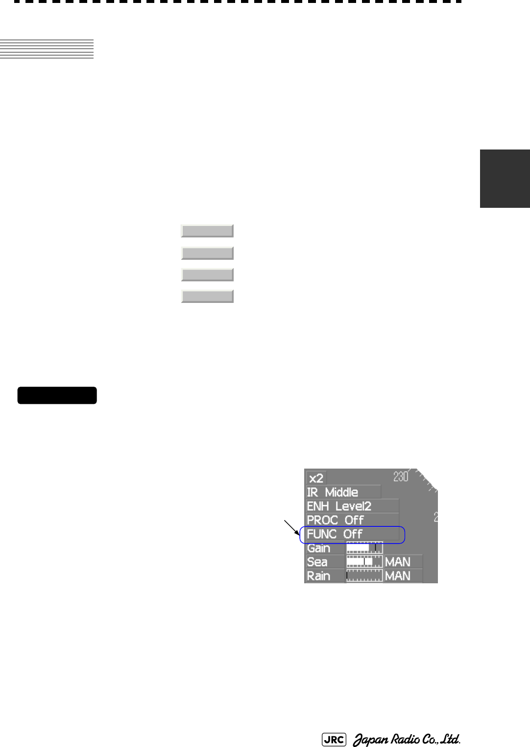
JMA-9100 Instruction Manual > 3.BASIC OPERATION > 3.9 USE FUNCTION KEY [USER]
3-111
3
3.9 USE FUNCTION KEY [USER]
"Radar Function Setting" is provided for easily obtaining the best radar video by
storing complex radar signal processing settings in the optimum status by use, and
calling the setting in accordance with the conditions for using the function.
Functions are factory-set for general use, and the settings can be fine adjusted by
operating the menu.
Four function modes are available, and they are factory-set as follows:
3.9.1 Operation Procedures
3.9.1.1 Calling a Function
Procedures
1) Press the [USER] key.
Each time the [USER] key is pressed, the selection changes cyclically as follows:
Function Off →Function1 →Function2 →Function3 →Function4 →Function Off
The name of the current function
mode is displayed at the lower left
of the display.
Alternatively, left-clicking the
function button located at the
lower left of the radar display will
enable the same operation.
3.9.1.2 Changing Function Setting (temporary change)
When radar signal processing setting is changed by using the menu or button on the radar
display while function 1 to 4 is called, the change is temporarily reflected to the operating
state.
Since this method does not change the memory contents, the new setting is discarded as soon
as another function is called.
When the previous function is called again, operation is performed according to the memory
contents.
Function 1: Useful for observing short-range videos.
Function 2: Suitable for general ocean navigation.
Function 3: Useful for observing videos in stormy weather.
Function 4: Use this mode when sea clutter is not strong but
rain / snow clutter is strong.
Coast
Deep Sea
Storm
Rain
Function
(FUNC) mode

3-112
JMA-9100 Instruction Manual > 3.BASIC OPERATION > 3.9 USE FUNCTION KEY [USER]
3.9.1.3 Changing Function Setting (memory contents change)
To change the memory contents of functions 1 to 4, use the function setting menu.
For how to operate the function setting menu, see Section 3.9.3 "Overview of Function
Operations (User Function Setting)".
3.9.2 Function Setting Menu Items
The function setting menu has the items below.
page 1 Option
1. Mode Name of the mode to be used Coast/Deepsea/....
2. IR Radar interference rejection Off/Low/Middle/High
3. Process Video process PROC Off/3Scan CORREL/....
4. Target Enhance Target expansion Off/Level1/Level2/Level3
5. AUTO Sea/Rain Automatic clutter suppression Off / AUTO Sea / AUTO Sea/Rain
6. Save Present State Saving the present state
page 2 Option
1. Pulse Length 0.75NM Standard pulse length for 0.75nm range SP1/MP1
2. Pulse Length 1.5NM Standard pulse length for 1.5nm range SP1/MP1/MP2/MP3
3. Pulse Length 3/4NM Standard pulse length for 3nm range MP1/MP2/MP3/LP1
4. Pulse Length 6/8NM Standard pulse length for 6nm range MP1/MP2/MP3/LP1/LP2
5. Pulse Length 12NM Standard pulse length for 12nm range MP1/MP2/MP3/LP1/LP2
6. Pulse Length 16NM Standard pulse length for 16nm range MP1/MP2/MP3/LP1/LP2
page 3 Option
1. Video Latitude Dynamic range of radar video Narrow/ Normal /Wide/Super Wide
2. Video Noise Rejection Radar video noise rejection Off/Level1/Level2
3. AUTO Dynamic Range Automatic dynamic range control Off/On
4. Process Switch Radar video process switching Off/Range FIX/AUTO
5. 2nd Process Mode 2nd video process mode PROC Off/3Scan CORREL/....
6. Process Switch Range Video process switching range
7. Fast Target Detection Off/On
page 4 Option
1. Trails Interval Radar trails length Off/15sec/....
2. Trails Mode True/Relative
3. Trails Reference Level Radar trails plotting threshold Level1-4
4. Trails Reduction Thinning of radar trails Off/Level1-3
6. Trails Process Superimpose-display of time radar trails and
continuous radar trails.
Off/On
7. Max Interval Maximum time for radar trails display Short/Middle/Long
page 5 Option
1. Gain Offset Gain correction
2. PRF Transmitting repetition frequency Normal/Economy/High Power
3. Small Buoy Detection Small target detection mode Off/On
4. Fishnet Detection Fishnet detection mode Off/On
5. Antenna Height Default/-5m/5-10m/10-20m/20m
8. Set Mode Default
9. Initialize

JMA-9100 Instruction Manual > 3.BASIC OPERATION > 3.9 USE FUNCTION KEY [USER]
3-113
3
3.9.3 Overview of Function Operations (User Function Setting)
The following outlines the operation of each function selected from the function
setting menu:
Procedures
1) Open the Process Setting menu by performing the menu
operation below.
→
→
→
The User Function Setting menu will appear.
Specify the number for the function for which the settings are to be changed.
The following are the operation overviews of each function setting item.
page 1-[1] Mode
•Selects the function name to be indicated at the lower left of the radar display
when the function is selected.
•When the setting is changed back to the factory setting, the initial value of the
selected mode is called.
•The following 11 modes are provided:
: Use this mode to monitor a relatively short range, for example, bays
and coasts where many boats and ships are running. (Importance is
attached to resolution.)
: Use this mode to monitor a relatively long range, for example, the open
sea. (Importance is attached to long-range gain.)
: Use this mode to detect small targets such as fishnets of round haul
netters hidden by sea clutter returns. (Importance is attached to sea
clutter suppression, and gain to moving targets lowers.)
: Use this mode when many rain / snow clutter returns or sea clutter
returns are detected in stormy weather. (Importance is attached to rain /
snow clutter and sea clutter suppression, and gain slightly lowers.)
: Use this mode when only a few rain / snow clutter returns or sea clutter
returns are detected.
: Use this mode when sea clutter is not strong but rain / snow clutter is
strong. (Importance is attached to rain / snow clutter suppression, and
gain slightly lowers.)
: Use this mode to detect flocks of sea birds.
: Use this mode to monitor utmost distances in the broad ocean.
: Use this mode to detect small targets like radio buoys in areas outside
the sea clutter area. (This mode displays targets of which detection
probability is low.)
: General mode used when the nine modes above are not applicable.
: General mode used when the nine modes above are not applicable.
Main
3. RADAR Menu
1. Process Setting
8. User Function Setting
Coast
Deep Sea
Fish Net
Storm
Calm
Rain
Bird
Long
Buoy
User1
User2

3-114
JMA-9100 Instruction Manual > 3.BASIC OPERATION > 3.9 USE FUNCTION KEY [USER]
page 1-[2] IR (Radar interference rejection)
•Same function as IR Setting described in Section 3.4.1 "Interference Rejection
(IR)".
page 1-[3] Process (Video process)
•Same function as PROCESS Setting described in Section 3.4.4 "Use Video
Processing (PROC)"
page 1-[4] Target Enhance
•Same function as TARGET ENHANCE Setting described in Section 3.4.3
"Target Enhance (ENH)".
page 1-[5] Auto STC/FTC (Auto Sea/Rain)
•Detects unwanted waves such as rain/snow clutter and sea clutter and
automatically suppresses them.
•When the sea state or weather changes, this function automatically performs
suppression processing in accordance with the situation.
•Suppression processing is not full automatic, and requires the operator to adjust
the afterimages of unwanted waves.
•To adjust the afterimage of sea clutter, use the [SEA] dial.
•To adjust the afterimage of rain/snow clutter, use the [RAIN] dial.
•In areas where the density of unwanted waves is low, unwanted waves may
remain being judged as targets. Thus, use the automatic clutter suppression
mode together with the video process mode.
•Characteristics of the automatic clutter suppression function:
: Disables the automatic clutter suppression function. Select off
when rain / snow clutter and sea clutter are not strong or when the
ship is in a bay.
: Automatically detects the strength of sea clutter, and performs the
most suitable sea clutter suppression processing.
Even when the strength of sea clutter varies depending on the wind
direction, AUTO Sea performs the most suitable suppression
processing. Land like islands can be displayed naturally.
Since rain clouds outside sea clutter areas are recognized as land,
there is no effect of suppressing rain / snow clutter.
: Along with AUTO Sea, AUTO Rain automatically detects the
strength of rain / snow clutter, and performs the most suitable rain /
snow clutter suppression processing.
When rain clouds are scattered about, AUTO Rain performs rain /
snow clutter suppression processing for only the rain-cloud areas.
Since land is recognized as rain clouds, land videos become
obscure.
Off
AUTO Sea
AUTO Sea/Rain

JMA-9100 Instruction Manual > 3.BASIC OPERATION > 3.9 USE FUNCTION KEY [USER]
3-115
3
page 2-[1]~[7] PL (Pulse Length)
•Sets the standard transmitter pulse length in each range.
•When the range is called, the pulse range is used.
page 3-[1]~[7] Video setting menu (Process Setting)
•Operation is the same as that of the Process Setting menu described in Section
3.8.1 "Set Radar Signal Processing (Process Setting)".
page 4-[1]~[7] Radar trails settings (Trails Setting)
•Same functions as in the Trails Setting of the RADAR Menu described in
Section 3.8.2 "Set Radar Trails (RADAR Trails Setting)".
page 5-[1] Gain Offset
•Corrects gain while the function mode is called.
•Since the displayed noise level varies depending on the combination of the
video process mode and the interference rejection level, gain needs fine
adjustment for always obtaining the highest level.
•The gain correction function saves the correction value set by the gain adjust in
each function mode, so it can obtain the highest gain without the gain adjust
being operated when the function mode is changed.
•To set high gain, set a value on the “+” side.
•To set low gain, set a value on the “-” side.
•When the radar interference rejection level is increased, the noise level is
lowered. Thus, set a gain correction value to the “+” side.
•When the video process mode , , or
is used, the noise level is lowered. Thus, set a gain correction
value to the “+” side.
•When the video process mode or is used,
noise is hard to disappear. Thus, set a gain correction value to the “-” side.
page 5-[2] PRF
•Same function as in the TXRX Setting described in Section 3.8.3 "Set Scanner
Unit (TXRX Setting)".
3Scan CORREL
4Scan CORREL
5Scan CORREL
Remain Peak Hold

3-116
JMA-9100 Instruction Manual > 3.BASIC OPERATION > 3.9 USE FUNCTION KEY [USER]
page 5-[3] Small Buoy Detection
•Reduces the loss of signal processing during detection of small targets.
page 5-[4] FishNet Detection
•Use this mode to detect small targets hidden by sea clutter returns.
•This function becomes more effective when the AUTO RAIN clutter
suppression function is used together.
page 5-[5] Antenna Height
•Set the height of radar antenna above sea level.
•The STC/FTC curve is changed.
:Activates the general signal processing mode.
:Activates the small buoy detection mode that reduces the loss
of signal processing.
:Activates the general signal processing mode.
:Activates the fishnet detection mode.
: Set default
: Set the antenna height under 5m.
: Set the antenna height 5m to 10m.
: Set the antenna height 10m to 20m.
: Set the antenna height over 20m.
Off
On
Off
On
Default
~5m
5m~10m
10m~20m
20m~
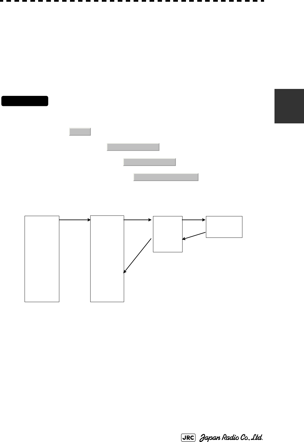
JMA-9100 Instruction Manual > 3.BASIC OPERATION > 3.9 USE FUNCTION KEY [USER]
3-117
3
3.9.4 Overview of saved Function Setting Data
The overview of saved function setting data is as follows:
Procedures
1) Open the User Function Setting menu by performing the menu
operation below.
→
→
→
page 1-[1] Mode
•Calls the default value of the mode, and saves it for the function number.
page 1-[6] Save Present State
•The currently operating state can be saved for the function number.
•Use this function to save the state of good setting that will be frequently used.
page 5-[8] Set Mode Default
•Saves the setting of the current function number, as the default setting of the
mode.
page 5-[9] Initialize
•Changes the memory contents of the mode, which is used with the current
function number, back to the factory setting.
Factory-set data: : Saved data that general operation cannot change
Default data: : Standard data of each function mode that users can change
Data that can be
called:
: Saved data that can be called by pressing the [USER] key
Main
3. RADAR Menu
1. Process Setting
8. User Function Setting
Coast
Deepsea
Fishnet
Storm
Calm
Rain
Bird
Long
Buoy
User1
User2
Coast
Deepsea
Fishnet
Storm
Calm
Rain
Bird
Long
Buoy
User1
User2
FUNC1
FUNC2
FUNC3
FUNC4
Present
【USER】
FUNCTION SETTING
Factory-set data
FUNCTION SETTING
Default data
FUNCTION SETTING
Data that can be called Current data
5-[8
1-[1
5-[9
1-[6

3-118
JMA-9100 Instruction Manual > 3.BASIC OPERATION > 3.10 USE USER SETTING
3.10 USE USER SETTING
The operation status of the radar is recorded. If the system is operated by more
than one operator, the operators can register operation status as suitable for them
and call the status. Operation status for up to five operations can be registered, and
a name can be assigned to each status. (Up to 10 alphanumeric characters)
3.10.1 Save Operating State (Save User Setting)
The system's current operating state can be saved in the system by performing the
operation below.
Procedures
1) Open the Save User Setting menu by performing the menu
operation below.
→
→
→
The Save User Setting menu will appear.
2) Left-click the button for the file to be saved.
The file name input screen will appear.
3) Enter a file name to be saved.
The Input File Name menu will appear.
On the numeric value input screen, enter a file name.
After the file name has been entered, the operating conditions will be saved.
Data saved by the user setting
Display Color Setting
Buzzer Volume
Option Key Setting
Date Display Style
EBL/VRM Control CURS
Cursor Length
Main
7. Sub Menu
3. User Setting
2. Save User Setting

JMA-9100 Instruction Manual > 3.BASIC OPERATION > 3.10 USE USER SETTING
3-119
3
3.10.2 Load Operating State (Load User Setting)
The operating state saved in the system can be loaded by performing the operation
below.
When the operating state is loaded, the previous operating state data is discarded.
Therefore, if you do not want to discard the operating state data, save the
operating state by performing the operation described in Section 3.10.1 "Save
Operating State (Save User Setting)".
Procedures
1) Open the Load User Setting menu by performing the menu
operation below.
→
→
→
The Load User Setting menu will appear.
2) Left-click the button for the file to be loaded.
Confirmation Window will appear.
To load the file, left-click the button.
3.10.3 Delete Operating State (Delete User Setting)
The operating state saved in the system can be deleted by performing the
operation below.
Use this function to delete unnecessary operating state data.
Procedures
1) Open the Delete User Setting menu by performing the menu
operation below.
→
→
→
The Delete User Setting menu will appear.
2) Left-click the button for the file to be deleted.
Confirmation Window will appear.
To delete the file, left-click the button.
Main
7. Sub Menu
3. User Setting
1. Load User Setting
1. Yes
Main
7. Sub Menu
3. User Setting
1. Load User Setting
1. Yes

3-120
JMA-9100 Instruction Manual > 3.BASIC OPERATION > 3.11 USING CARD
3.11 USING CARD
This radar has two card slots. Inserting a flash memory card (option) into a card
slot, you can save the following contents, saved in the processor, in the card or can
load data from the card to the processor.
These pieces of information can be saved in a flash memory card as a file. The
internal capacity is as large as only a file. An internally created file can be saved
until the flash memory card is full.
3.11.1 Operate File on the Card (File Manager)
Procedures
1) Insert a flash memory card into the card slot.
Flash memory card (option) is necessary.
2) Set the radar in the standby state.
While the radar is in the transmission state, the File Manager screen cannot be opened.
3) Open the File Manager window by performing the menu
operation below.
→
Trails of own ship: 7000 points maximum
Track of other ship: 20 target X 500 points
Mark/Line: 20000 points maximum
WPT: 512 points maximum
Route: 1 route maximum
Main
2. File Manager
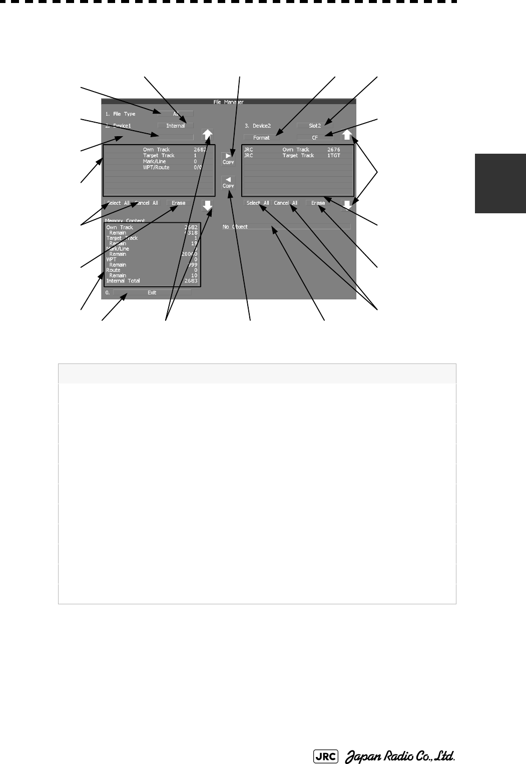
JMA-9100 Instruction Manual > 3.BASIC OPERATION > 3.11 USING CARD
3-121
3
The File Manager window will appear.
•The file name and data saved in the selected device will be displayed.
•Pressing the arrows located at the upper right and lower right of the file name
list will scroll the list.
Information saved in the processor is displayed in the Memory Content.
Own Track : Number of data points for own ship's track (7000 points maximum)
Remain : Number of remaining data points of own ship's track that can be saved
Target Track : The number of other ships' trails (up to 20 targets)
Remain : The remaining number of other ships' trails to be saved
Mark/Line : Number of mark and line points made with user map (up to 20000 items)
Remain : Number of remaining data points of marks and lines that can be saved
WPT : Number of data points of created waypoints (512 points maximum)
Remain : Remaining waypoints that can be saved
Route : Number of data points of created routes (1 route maximum)
Remain : Remaining routes that can be saved
Internal Total : Total number of data points
Exit
Device 2 file list
scroll
Device 2
selected
Device 2 format
Copy file from
device 1 to device 2
Copy file from
device 2 to device 1
Device 2 erase
selected file
Device 1
select and
cancel all files
Device 1 erase
selected file
Device 1 selected
Type of file
displayed
Device 2
select and
cancel all files
Device 1 file list
scroll
Device 2
device type
Device 1
device type
Device 1 format
Processor saved
information
Device 1 saved
information
Device 1 saved
information
Message
3-122
JMA-9100 Instruction Manual > 3.BASIC OPERATION > 3.11 USING CARD
3.11.1.1 Copy Internal Information to Card (Copy Internal -> Card)
Procedures
1) While the File Manager window is open, left-click the device 1
selection button.
Selected items for Device1 will be displayed.
2) Left-click the button among the selection items.
Internal is selected.
3) Left-click the device 2 selection button.
Selected items for Device2 will be displayed.
4) Left-click button corresponding to the device to which data is to
be copied.
The list of files saved in the selected device will be displayed.
5) Put the cursor on the data to be copied, and Left-click button.
Left-click button one more time will cancel the selection.
6) Left-click the button.
The character input screen for the Input File Name menu will appear.
7) Enter the file name to be saved.
Up to 10 characters can be entered.For the input method on the character input screen, see
Section 3.3.4.7 "Entering a character".
After the data has been entered, Confirmation Window will appear.
8) Left-click the button.
The entered name is written into the selected device as a file name.
Up to the maximum number of items, described on the previous page, can be saved in the
device. With regard to the capacity for saving data, data can be saved on a flash memory card
as a file, and those files can be saved until the flash memory card is full.
1. Internal
COPY
1. Yes

JMA-9100 Instruction Manual > 3.BASIC OPERATION > 3.11 USING CARD
3-123
3
3.11.1.2 Load Information from Card to Internal Portion (Copy Card ->
Internal)
Procedures
1) While the File Manager window is open, left-click the device 1
selection button.
Selected items for Device1 will be displayed.
2) Left-click the button among the selection items.
Internal is selected.
3) Left-click the device 2 selection button.
Selected items for Device2 will be displayed.
4) Left-click button corresponding to the device in which data to be
loaded is saved.
The list of files saved in the selected device will be displayed.
5) Select the desired data.
Left-click button one more time will cancel the selection.
6) Left-click the button.
Confirmation Window will appear.
7) Left-click the button to overwrite data, or Left-click
the button to add new data.
When Overwrite is selected, internally saved data is deleted and new data is loaded. When
Add is selected, new data is added to the saved data.
8) Left-click the button.
The selected file is loaded into the system from the card.
When adding data saved on the card to the data saved in the system, data can be copied from
multiple files. However, when the maximum number of units of data is reached, additional
data cannot be loaded. Even in the ADD mode, WPT data and Route data are overwritten.
1. Internal
COPY
1. Overwrite
2. Add
1. Yes
3-124
JMA-9100 Instruction Manual > 3.BASIC OPERATION > 3.11 USING CARD
3.11.1.3 Copy Information (Copy)
Procedures
1) While the File Manager window is open, left-click the device 1
selection button.
Selected items for Device1 will be displayed.
2) Left-click the button corresponding to the device from which data
is to be copied.
The list of files saved in the selected device will be displayed.
3) Left-click the device 2 selection button.
Selected items for Device2 will be displayed.
4) Left-click button corresponding to the device to which data is to
be copied.
The list of files saved in the selected device will be displayed.
5) Put the cursor on the data to be copied, and Left-click button.
Left-click button one more time will cancel the selection.
6) Left-click the button.
The character input screen for the Input File Name menu will appear.If there is a file having
the same name, the file selection window will appear.
7) When deleting saved data and copying new data, left-click
to select Overwrite. When adding data to a
destination file, left-click to select Add. Even in the Add
mode, WPT data and Route data are overwritten. When selection
has been made, Confirmation Window will appear.
8) Enter the file name to be saved.
Up to 10 characters can be entered. For the input method on the character input screen, see
Section 3.3.4.7 "Entering a character"
After the data has been entered, Confirmation Window will appear.
9) Left-click the button.
The entered name is written into the selected device as a file name.
COPY
1. Overwrite
2. Add
1. Yes

JMA-9100 Instruction Manual > 3.BASIC OPERATION > 3.11 USING CARD
3-125
3
3.11.1.4 Erase File (Erase)
Procedures
1) While the File Manager window is open, left-click the device 1
selection button.
Selected items for Device1 will be displayed.
2) Left-click button corresponding to the device in which data to be
erased is saved.
The list of files saved in the selected device will be displayed.
3) Select data to be erased.
Left-click button one more time will cancel the selection.
4) Left-click button.
Confirmation Window will appear.
5) Left-click the button.
The selected file will be erased.
3.11.1.5 Initializing a card (Format)
Procedures
1) While the File Manager window is open, left-click the device 1
selection button or the device 2 selection button.
Selection items for Device1 or Device2 will appear.
2) Left-click the button which corresponds to the system (device)
where data to be displayed is saved.
The File Manager window will appear.
3) Put the cursor on for the device to be initialized, and
Left-click button.
Confirmation Window will appear.
4) Left-click the button.
Initialization will be executed.
Erase
1. Yes
Format
1. Yes

3-126
JMA-9100 Instruction Manual > 3.BASIC OPERATION > 3.11 USING CARD
3.11.1.6 Showing data saved on the card (Show Card)
Procedures
1) While the File Manager window is open, left-click the device 1
selection button.
Selected items for Device1 or Device2 will be displayed.
2) Left-click button corresponding to the device in which data to be
displayed is saved.
The list of files saved in the selected device will be displayed.
Exit
1) Left-click the button.
The File Manager menu will close.
1. Exit

MEASUREMENT OF RANGE AND BEARING
4.1 USE OF NAVIGATION TOOLS ..............................................................4-1
4.1.1 Using Cursor (Cursor) ....................................................................4-2
4.1.2 Using Range Rings (Range Rings) ................................................4-2
4.1.3 Using Electronic Bearing Line (EBL1/EBL2) ................................4-3
4.1.4 Using Parallel Index Lines (PI Menu) .............................................4-8
4.1.5 Operating EBL Maneuver Function (EBL Maneuver Setting) ....4-14
4.1.6 Operating EBL, VRM, and PI with Cursor ...................................4-16
4.2 MEASUREMENT OF RANGE AND BEARING ....................................4-19
4.2.1 Measurement with Cursor Position (Cursor) ..............................4-19
4.2.2 Measurement with Electronic Bearing Line and Variable Range
Marker [EBL] [VRM] .....................................................................4-20
4.2.3 Measurement with Two Arbitrary Points .....................................4-21
SECTION 4
MEASUREMENT OF RANGE AND
BEARING
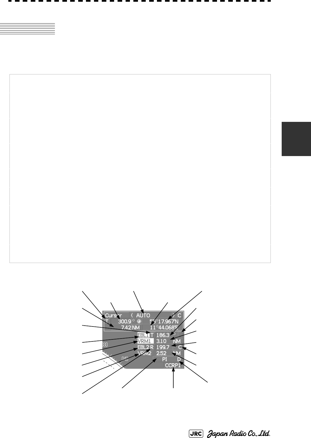
JMA-9100 Instruction Manual > 4.MEASUREMENT OF RANGE AND BEARING > 4.1 USE OF NAVIGATION TOOLS
4-1
4
4.1 USE OF NAVIGATION TOOLS
The system is equipped with the navigation tools below.
Cursor: Specifies an arbitrary point, and measures the range and bearing
from the own ship.
Range Rings: Displays concentric circles with own ship's position as the center at
specified intervals, and the rings are used as rough guides for range
measurement.
Electronic Bearing Line
(EBL1/2):
Displays a straight line for specifying an arbitrary bearing, and
measures the bearing from the own ship.The process unit is
equipped with two electronic bearing lines.
Variable Range Marker
(VRM1/2):
Displays a circle for specifying an arbitrary range, and measures the
range from the own ship.The process unit is equipped with two
variable range markers.
Parallel Index Line (PI): Displays straight lines at even intervals, and the lines are used as
rough guides for complex measurement or ship courses.
EBL Maneuver: Displays the course by steering the own ship, and it is used as a
rough guide for ship maneuvering.
Man Overboard: Stores the latitude and longitude where the own ship was at the
point of storing the markers, and shows an anchor symbol on the
radar display. When the own ship has moved, the system displays
the range and bearing to the position. Use this tool when the ship is
anchored or man overboard.
EBL/VRM/PI Operation with
Cursor (Cursor AUTO):
Operates EBL, VRM, or PI on the radar display by using the cursor.
EBL1 starting point mode
EBL2 starting point mode
Parallel index line
starting point mode
Cursor longitude
Cursor latitude
Consistent Common
Reference Point (CCRP)
Cursor mode
Cursor bearing
Cursor bearing
numeric value indication
true / relative
EBL1 bearing
VRM1 range
EBL2
numeric value indication
true / relative
EBL1
numeric value indication
true / relative
Cursor range
VRM2 range
EBL2 bearingEBL1 On / Off
VRM1 On / Off
VRM2 On / Off
EBL2 On / Off
Parallel index line
On / Off
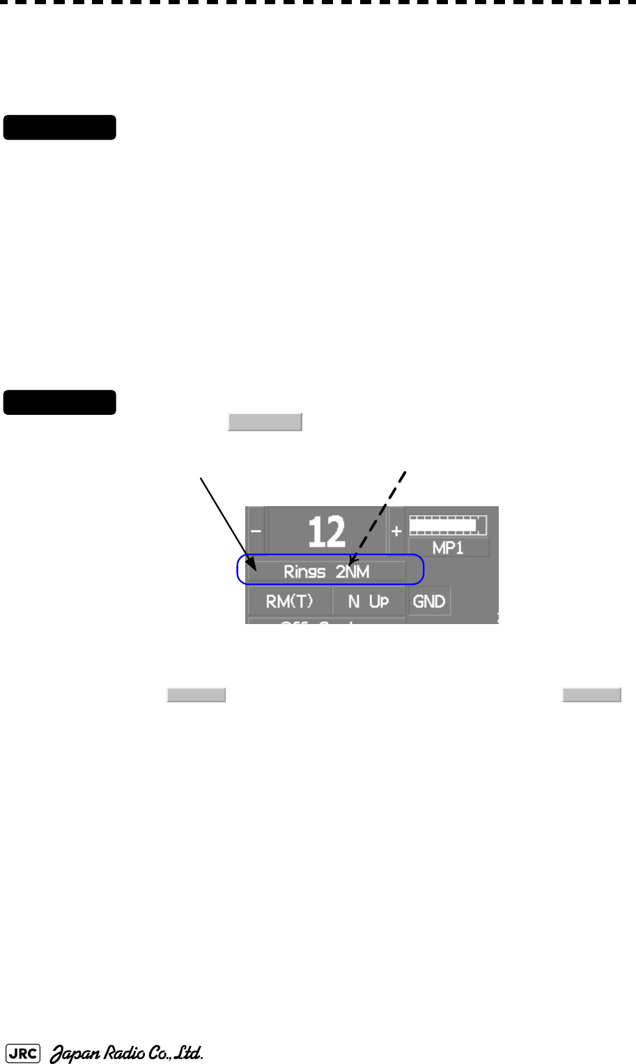
4-2
JMA-9100 Instruction Manual > 4.MEASUREMENT OF RANGE AND BEARING > 4.1 USE OF NAVIGATION TOOLS
4.1.1 Using Cursor (Cursor)
Procedures
1) Move the cursor onto the PPI display by moving the trackball.
When the cursor is moved onto the PPI display, the arrow cursor turns into a cross cursor.
4.1.2 Using Range Rings (Range Rings)
Procedures
1) Left-click the button on upper left area on the display.
The range ring display switches disappear and appear between display and non-display each
time the button is clicked. The range ring interval is shown in the
button.
The range between the target and own ship can be determined by visually measuring the
target's position that lies between two range rings.
For change of the brilliance of range rings, refer to Section 3.8.5 "Set Radar Display (Display
Setting)".
Rings
Range rings display On / Off Range rings interval
Rings Rings
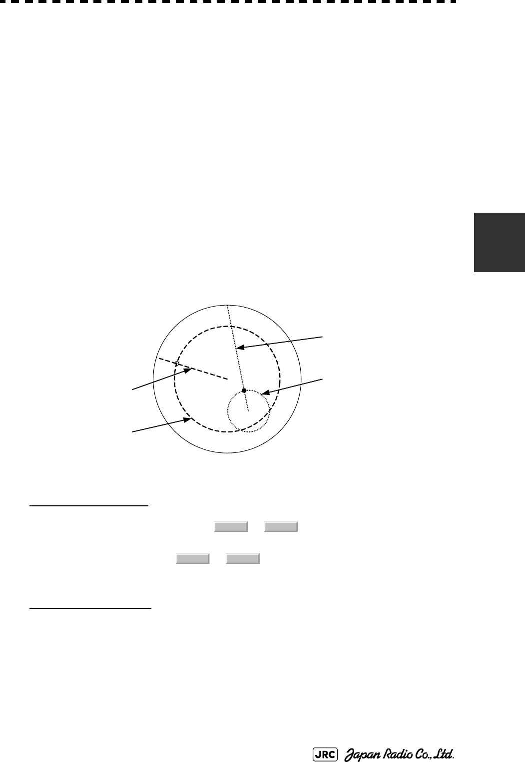
JMA-9100 Instruction Manual > 4.MEASUREMENT OF RANGE AND BEARING > 4.1 USE OF NAVIGATION TOOLS
4-3
4
4.1.3 Using Electronic Bearing Line (EBL1/EBL2)
Electronic bearing lines (EBL) are indispensable to the measurement of bearings.
Operators must be familiar with the operation of EBL beforehand.
The system is equipped with two EBL. The bearing and starting point of an EBL
can be operated separately from the other EBL.
An intersection marker is displayed at the intersection point of the EBL and VRM
of the same number.
EBL Bearing Display
The bearing value of the current or on the PPI display is shown in the
upper right of the display.
The currently operable or is highlighted in the upper right of the display.
Starting Point of EBL
The starting point of the currently operating EBL can be switched from the center of the
radar display to any offset position . The offset position of the EBL starting point can be
fixed on the radar display or at the latitude and longitude. (The setting of the navigator is
necessary for fixing the offset position at the latitude and longitude.)
Intersection markers shown on EBL:
○:EBL1, VRM1
●:EBL2, VRM2
VRM2
EBL2
VRM1
EBL1
EBL1 EBL2
EBL1 EBL2

4-4
JMA-9100 Instruction Manual > 4.MEASUREMENT OF RANGE AND BEARING > 4.1 USE OF NAVIGATION TOOLS
4.1.3.1 Operating EBL (EBL)
Procedures
1) Press the [EBL1] or [EBL2] key.
The EBL button (located at the upper right of the display) will be highlighted, and the
selected EBL becomes operable.
Turn the [EBL] dial.
To turn the [EBL] dial to the right, turn the EBL control clockwise; to turn the [EBL] dial to
the left, turn the EBL control counterclockwise.
Cancel
1) Press the [EBL1] or [EBL2] key again.
The selected EBL display will disappear.
4.1.3.2 Moving the Starting Point of EBL
The system provides three types of EBL starting points. Select one of them in
accordance with purpose.
[1] To move the starting point of EBL
Procedures
1) Make EBL1 or EBL2 operable.
2) Press the [EBL] dial to set or for the EBL1 / EBL2
starting point mode switching located at the upper right of the
display.
The selected EBL starting point mode is switched as shown below each time the dial is
pressed.
⇒ ⇒ ⇒
3) Put the cursor on the EBL starting point is to be moved, and left-
click.
The selected EBL starting point will be determined.
: The EBL starting point is defined as the own ship's position.
: The EBL starting point is moved and fixed on the radar display.
: The EBL starting point is moved and fixed at the latitude and
longitude. (The navigator needs to be connected.)
_
C
D
C D
_C D _

JMA-9100 Instruction Manual > 4.MEASUREMENT OF RANGE AND BEARING > 4.1 USE OF NAVIGATION TOOLS
4-5
4
[2] To return the EBL starting point to own ship's position
Procedures
1) Make EBL1 or EBL2 operable.
2) Press the [EBL] dial to set for the EBL1 / EBL2 starting point
mode switching located at the upper right of the display.
The selected EBL starting point will be set as the own ship's position.
4.1.3.3 Setting EBL Operation Mode
[1] To set the numeric value display mode of EBL (EBL Bearing REF)
Determine whether to display EBL in true bearing mode or relative bearing mode.
Procedures
1) Put the cursor on the EBL1/2 numeric value indication true /
relative switching (located at the upper right of the display), and
left-click.
The selected mode is switched as shown below each time the left button is
clicked. ⇒ ⇒
[2] To set a mode for fixing EBL display (EBL Bearing Fix)
When this function is set to Angle , an EBL is fixed to the preset bearing. For
example, if a true bearing of 020° is preset, the EBL is fixed to the true bearing
020° even when the own ship turns.
When the function is set to Screen , the EBL is fixed on the radar display. In this
case, the EBL is always fixed to the same bearing on the display when the own
ship turns.
:EBL bearing is displayed in true bearing mode.
:EBL bearing is displayed in relative bearing mode.
_
T R T
T
R
4-6
JMA-9100 Instruction Manual > 4.MEASUREMENT OF RANGE AND BEARING > 4.1 USE OF NAVIGATION TOOLS
Procedures
1) Open the EBL/Cursor Setting menu by performing the following
menu operation.
→
→
2) Left-click at the item button
of or .
Variable range markers (VRM) are indispensable to the measurement of ranges.
Operators must be familiar with the operation of VRM beforehand.
The system is equipped with two VRM. The VRM can be operated separately
from each other.
An intersection marker is displayed at the intersection point of the VRM and EBL
of the same number.
When the starting point of an EBL is offset, the center of the VRM is defined as
the offset EBL starting point.
:EBL bearing is fixed to the preset value.
:EBL bearing is fixed on the radar display.
i
Course data is necessary for turning on this
function.
Intersection markers shown on VRM:
○:EBL1, VRM1
●:EBL2, VRM2
Main
7. Sub Menu
9. EBL/Cursor Setting
1. EBL1 Bearing FIX 2. EBL2 Bearing FIX
Angle
Screen
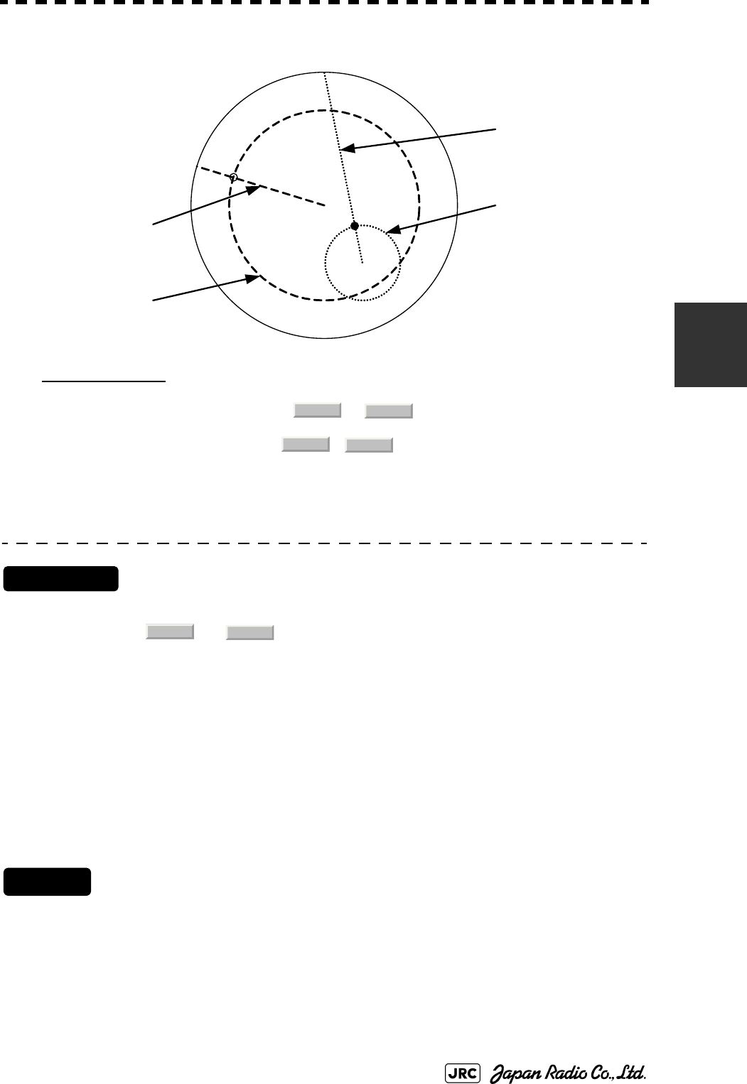
JMA-9100 Instruction Manual > 4.MEASUREMENT OF RANGE AND BEARING > 4.1 USE OF NAVIGATION TOOLS
4-7
4
VRM Operation
The range value of the current or on the PPI display is shown in the
VRM1/2 range located at the upper right of the display. The currently operable VRM1 or
VRM2 is highlighted in the button located at the upper right of the
display.
4.1.3.4 To operate VRM (VRM)
Procedures
1) Press the [VRM1] or [VRM2] key.
The and buttons (located at the upper right of the display) will be
highlighted, and the selected VRM becomes operable.
2) Turn the [VRM] dial.
To turn the [VRM] dial to the right, the VRM control wide, to turn the [VRM] dial to the
left, the VRM control narrow.
Cancel
1) Press the [VRM1] or [VRM2] key again.
The selected EBL display will disappear.
VRM2
EBL2
VRM1
EBL1
VRM1 VRM2
VRM1 VRM2
VRM1 VRM2
4-8
JMA-9100 Instruction Manual > 4.MEASUREMENT OF RANGE AND BEARING > 4.1 USE OF NAVIGATION TOOLS
4.1.4 Using Parallel Index Lines (PI Menu)
Parallel index lines can be displayed.
4.1.4.1 Operating Parallel Index Lines (PI)
Procedures
1) Press the [VRM] dial.
Parallel index lines and the PI Menu will appear.
To change the bearing of parallel index lines, turn the [EBL] dial, to change the line interval,
turn the [VRM] dial.
The bearing and interval of parallel index lines are displayed in the PI Menu.
2) Press the [VRM] dial again.
The parallel index lines will be fixed.
Cancel
1) Press the [VRM] dial again.
The parallel index line display will disappear.
4.1.4.2 Operation of Parallel Index Lines
•Parallel index lines rotate in the same direction as you turn the [EBL] dial.(1,
2)
•The intervals of parallel index lines narrow when you turn the [VRM] dial
counterclockwise (3), and widen when you turn the [VRM] dial clockwise
(4).
•When the [VRM] dial is pressed, the PI Menu closes and the parallel index
lines are fixed.
i
Parallel index lines are operable only while the PI Menu is
displayed. When the menu is closed, the parallel index line
display remains, but the settings of the bearing and interval
cannot be adjusted any more. To adjust the bearing and
interval after closing the menu, press the [VRM] dial twice to
open the PI Menu.
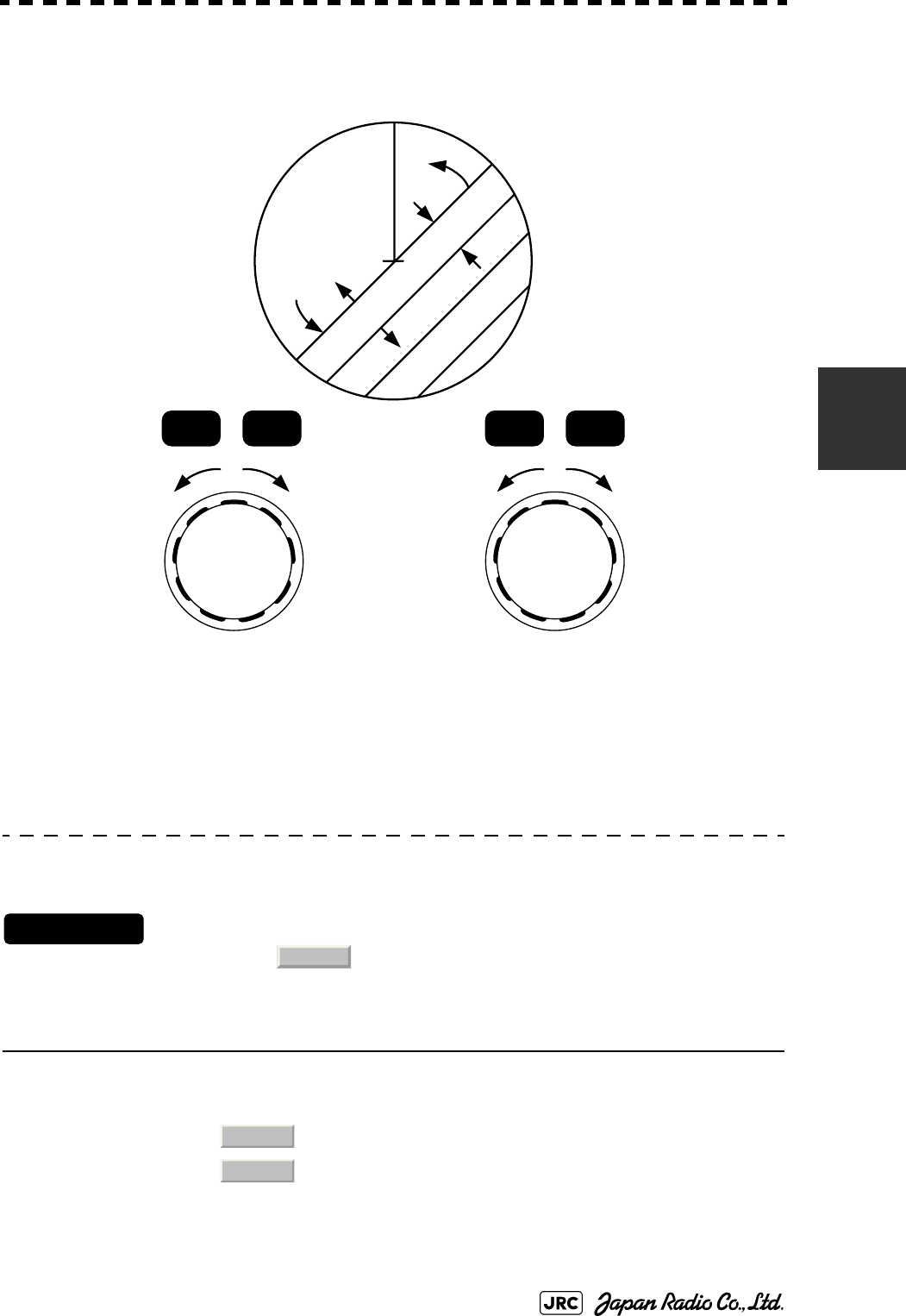
JMA-9100 Instruction Manual > 4.MEASUREMENT OF RANGE AND BEARING > 4.1 USE OF NAVIGATION TOOLS
4-9
4
During the operation of parallel index lines, pressing the [EBL1] or [EBL2] key
disables operation for rotation directions. Pressing the [VRM1] or [VRM2] key
disables operation for parallel index line intervals.
4.1.4.3 Settings in PI Menu (PI Menu)
The operation of parallel index lines can be set in the PI Menu.
Procedures
1) Left-click the button to open the PI menu.
[1] Display for All Lines
Sets the parallel index line display to on or off.
:Parallel index lines are displayed.
:Parallel index lines are not displayed.
HL
②
①
③
④
②①④③
EBL1 EBL2 VRM 1 VRM 2
PI
On
Off
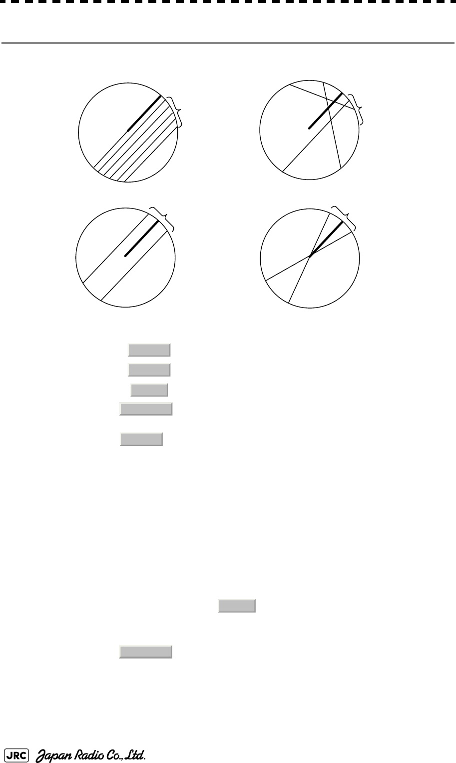
4-10
JMA-9100 Instruction Manual > 4.MEASUREMENT OF RANGE AND BEARING > 4.1 USE OF NAVIGATION TOOLS
[2] Operation Mode
Sets an operation mode for parallel index lines.
a. Operation if is selected
•A line perpendicular to the own ship and the intersection marker "----○" are
displayed on an operable line.
•Turning the [EBL] dial changes the direction.
•Pressing the [VRM] dial changes the range, end point 1, or end point 2 to be
operated.
•An operable point is displayed with "● " and can be operated by turning the
[VRM] dial.
•If Sequential is selected for [3] Control, the parallel index lines of the next
number can be displayed by pressing the [EBL] dial.
•To close the menu, left click software button.
b. Operation if is selected
•Select a group of lines to be operated according to the setting of [3] Control.
•Pressing the [EBL] dial switches between the direction change mode and
elevation-angle change mode. Turning the [EBL] dial changes the direction or
elevation angle.
:All the parallel lines are operated at the same time.
:The bearing of each line is operated individually.
:Equally spaced lateral lines are displayed on both sides.
:Two lines intersecting at the center of a circle are displayed.
All
PI
Individual
PI
Track
PI
Equiangular
PI
All
Individual
Track
Equiangular
Individual
0.Exit
Equiangular
JMA-9100 Instruction Manual > 4.MEASUREMENT OF RANGE AND BEARING > 4.1 USE OF NAVIGATION TOOLS
4-11
4
[3] Control
Determines whether to operate all the lines at the same time. The setting items are
determined by the setting of Section [2] "Operation Mode".
a. If is selected
The setting cannot be changed.
b. If is selected
Determine whether to set consecutive lines or individual lines.
c. If or is selected
Select a group of lines to be operated.
[4] Floating
Moves the center point of parallel index lines.
[5] Heading Link
Determines whether to operate parallel index lines following the heading bearing.
:All the lines are operated at the same time.
:Lines are operated sequentially.
to :A specified line is operated.
to :A specified group is operated.
:The starting point of parallel index lines is defined as
the own ship's position.
:The center of parallel index lines is moved and fixed on
the radar display.
:The center of parallel index lines is moved and fixed at
the latitude and longitude. (The navigator needs to be
connected.)
:Parallel index lines are operated following the heading
bearing.
:Parallel index lines are not operated following the
heading bearing.
All
All
Individual
Sequential
Index Line1
Line8
Track
Equiangular
Group1 Group4
Off
Screen Fix
L/L Fix
On
Off
4-12
JMA-9100 Instruction Manual > 4.MEASUREMENT OF RANGE AND BEARING > 4.1 USE OF NAVIGATION TOOLS
[6] Next
Moves to the next page.
[7] Range Scale Link
Determines the operation of parallel index line intervals when the range is
changed.
[8] Reference Bearing
Sets a reference bearing for the numeric data display of parallel index lines. The
setting items are determined by the setting of Section [2] "Operation Mode"
a. If is selected
b. If is selected
:The intervals are fixed with the actual range (nm). The
appearance of parallel index line intervals changes
when the range is changed.
:The intervals are fixed with the display range. The
parallel index line intervals (nm) change when the
range is changed.
:Displayed with true bearing (with North as reference).
:Displayed with the heading line as reference.
:Displayed with true bearing (with North as
reference).
:Displayed with the heading line as reference.
to :Displayed with a specified line as reference.
On
Off
All
True
HL
Individual
True
HL
Index Line1 Line8
JMA-9100 Instruction Manual > 4.MEASUREMENT OF RANGE AND BEARING > 4.1 USE OF NAVIGATION TOOLS
4-13
4
c. If is selected
d. If is selected
The setting cannot be changed.
[9] Operation Area
If All is selected for Section [2] "Operation Mode", this function sets an area for
displaying parallel index lines.
[10]Display for Individual Line
Determines whether to turn on / off the parallel index line display of a selected
number.
: Displayed with true bearing (with North as
reference).
: Displayed with the heading line as reference.
to : Displayed with a specified line as reference.
Line1, Line3, Line5 and
Line7 correspond to
Group1, Group2, Group3
and Group4, respectively.
:Parallel index lines are displayed only on one side.
:Parallel index lines are displayed on both sides.
On :The line of the selected number is displayed.
Off :The line of the selected number is not displayed.
If is selected for Section [2] "Operation Mode", the
line near the own ship is .
If or is selected
for Section [2] "Operation Mode",
Line1, Line3, Line5 and Line7
correspond to Group1, Group2,
Group3 and Group4, respectively.
Track
True
HL
Index Line1
Line8
Line1
Line3
Line5
Line7
Group1
Group2
Group3
Group4
⇔
⇔
⇔
⇔
Equiangular
One Side
Both Side
All
Index Line1
Line1
Line3
Line5
Line7
Group1
Group2
Group3
Group4
⇔
⇔
⇔
⇔
Track
Equiangular
4-14
JMA-9100 Instruction Manual > 4.MEASUREMENT OF RANGE AND BEARING > 4.1 USE OF NAVIGATION TOOLS
4.1.5 Operating EBL Maneuver Function (EBL Maneuver Setting)
4.1.5.1 Initial Setting (EBL Maneuver Setting)
Procedures
1) Open the EBL Maneuver Setting menu by performing the
following menu operation.
→
2) Set the following parameters.
For inputs to the value input screen, refer to Section 3.3.4 "Operation on Numeric Value,
Latitude / Longitude and Character Input menu".
:Set the range from when the rudder is steered to when
the ship beings to turn.
:Select a turn mode.
:Turning radius (NM)
:Rate of turn (deg/min)
:Select the setting for turning.
If is selected :Turning radius (NM)
If is selected :Rate of turn (deg/min)
i
A wrong initial setting affects the maneuver curve function
explained below.
Main
1. EBL Maneuver Setting
Reach
Turn Mode
Radius
Rate
Turn Set
Radius
Rate
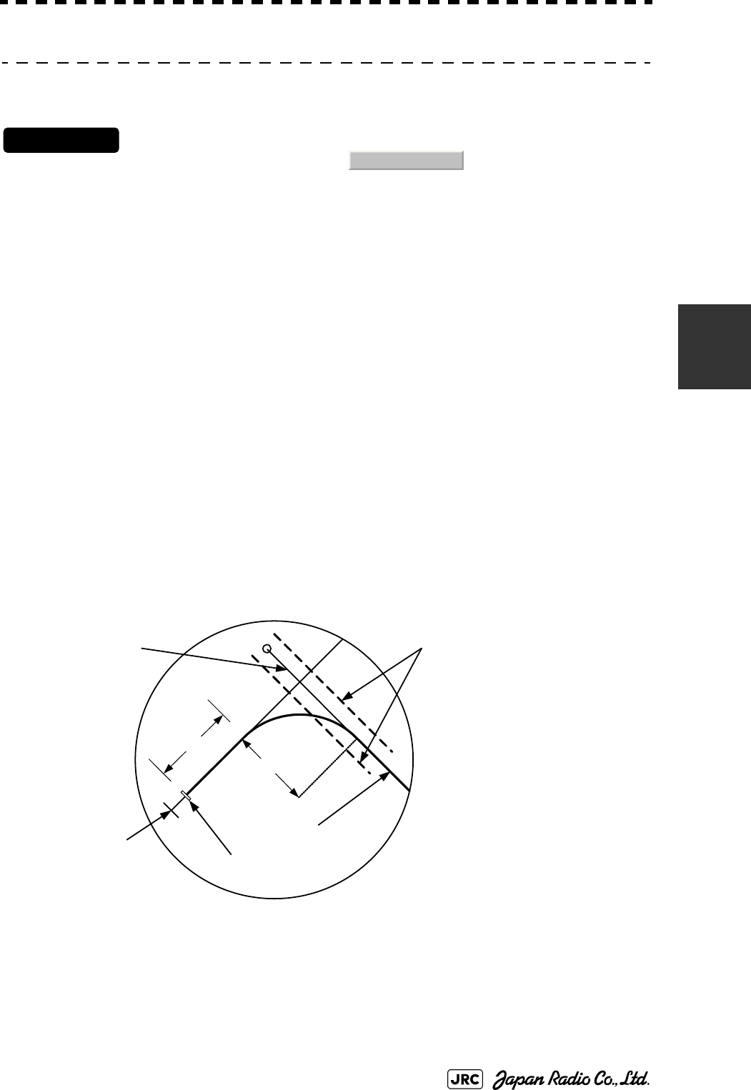
JMA-9100 Instruction Manual > 4.MEASUREMENT OF RANGE AND BEARING > 4.1 USE OF NAVIGATION TOOLS
4-15
4
4.1.5.2 Creation of Maneuver Curve (EBL Maneuver)
Procedures
1) Left-click the item button of while the EBL
Maneuver Setting menu is open.
The EBL maneuver function will be set to on or off.
A auxiliary line for maneuver curve creation, a maneuver curve, and a WOL will appear on
the radar display.
2) Put the cursor on the starting point of the auxiliary line, and set
the bearing of the auxiliary line by operating the [EBL] dial.
The bearing of the auxiliary line is the final bearing in which the own ship is to move.
The WOL position varies depending on the bearing of the auxiliary line.
If the WOL is behind the CCRP, the line color of WOL will change.
3) Left-click.
The setting will be determined. However, if the WOL is behind the CCRP position at this
point, left-clicking is rejected, and the setting is not determined.
1. EBL Maneuver
Scheduled route
Maneuver curve
Auxiliary line
Own ship’s position
WOL : Steering point
Reach : Range from when the rudder
is steered to when the ship
begins to turn
Radius : Turning radius
HL
Radius
WOL
Reach
4-16
JMA-9100 Instruction Manual > 4.MEASUREMENT OF RANGE AND BEARING > 4.1 USE OF NAVIGATION TOOLS
4.1.6 Operating EBL, VRM, and PI with Cursor
When the cursor mode is set to (located at the upper right of the
display), EBL, VRM, and PI can be operated simply by using the trackball.
4.1.6.1 Operating Electronic Bearing Line (EBL)
Procedures
1) Put the cursor on EBL1 or EBL2, and left-click.
When the cursor is moved to it, EBL1 or EBL2 is shown at the upper right of the cursor.
The EBL becomes operable when left-clicking.カーソルを合わせるとカーソル右上に
または が表示されます。左クリックすると操作状態になりま
す。
2) Move the cursor to the bearing to be set.
The EBL will move as the cursor moves.
3) Left-click.
The EBL will be fixed.
4.1.6.2 Operating Variable Range Marker (VRM)
Procedures
1) Put the cursor on VRM1 or VRM2, and left-click.
When the cursor is moved to it, or is shown at the upper right of
the cursor. The VRM becomes operable when left-clicking.
2) Move the cursor to the range to be set.
The VRM will move as the cursor moves.
3) Left-click.
The VRM will be fixed.
AUTO
EBL1 EBL2
VRM1 VRM2

JMA-9100 Instruction Manual > 4.MEASUREMENT OF RANGE AND BEARING > 4.1 USE OF NAVIGATION TOOLS
4-17
4
4.1.6.3 Operating EBL and VRM Concurrently (EBL・VRM)
Procedures
1) Put the cursor on the intersection marker ( ○ or ● ), and left-
click.
When the cursor is moved to it, or is
shown at the upper right of the cursor. The EBL and VRM become operable when left-
clicking.
2) Move the cursor to the bearing / range to be set.
The EBL and VRM will move as the cursor moves.
3) Left-click.
The EBL and VRM will be fixed.
4.1.6.4 Operating Parallel Index Lines (PI)
[1] To change the direction of parallel index lines
Procedures
1) Put the cursor on near the center of line, and left-click.
When the cursor is moved there, it will turn into and will be displayed at
the upper right of the cursor. The parallel index lines become operable when left-clicking.
2) Move the cursor to the direction to be set.
The parallel index lines will change the direction as the cursor moves.
3) Left-click.
The parallel index lines will be fixed.
EBL1 VRM1 EBL2 VRM2
PI

4-18
JMA-9100 Instruction Manual > 4.MEASUREMENT OF RANGE AND BEARING > 4.1 USE OF NAVIGATION TOOLS
[2] To change parallel index line intervals
Procedures
1) Put the cursor on near the end of line, and left-click.
When the cursor is moved there, it will turn into and will be displayed at
the upper right of the cursor. The parallel index lines become operable when left-clicking.
2) Move the cursor to the interval to be set.
The parallel index lines interval will change as the cursor moves.
If Individual is selected for Operation Mode, the parallel index lines move.
3) Left-click.
The parallel index lines will be fixed.
[3] To change the end points of parallel index lines
If Individual is selected for Operation Mode, the length of parallel index lines can
be changed.
Procedures
1) Put the cursor on the end point of parallel index lines, and left-
click.
When the cursor is moved there, it will turn into and will be displayed at
the upper right of the cursor. The parallel index lines become operable when left-clicking.
2) Move the cursor to the position to be set.
The position of the end point will change as the cursor moves.
3) Left-click.
The parallel index lines will be fixed.
PI
PI
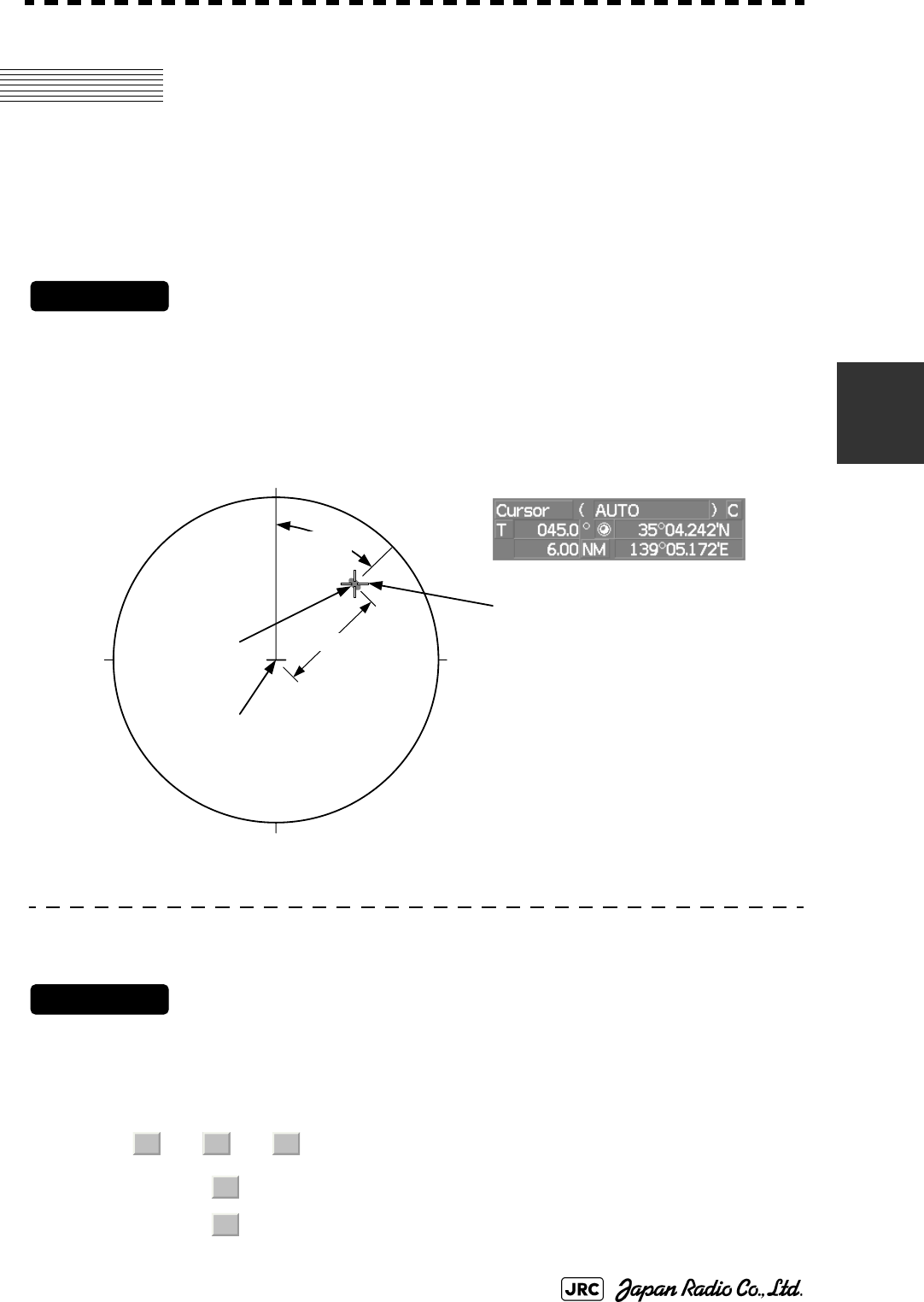
JMA-9100 Instruction Manual > 4.MEASUREMENT OF RANGE AND BEARING > 4.2 MEASUREMENT OF RANGE AND BEARING
4-19
4
4.2 MEASUREMENT OF RANGE AND
BEARING
4.2.1 Measurement with Cursor Position (Cursor)
Procedures
1) Make sure of the target echoes on the radar display.
2) Move the cursor to the target.
The bearing and range of the target will be shown in the Cursor bearing / range located at the
upper right of the display. The range is a distance from the own ship's position.
4.2.1.1 To set a cursor bearing numeric value mode
Determine whether to display a cursor bearing in true or relative bearing mode.
Procedures
1) Put the cursor on the Cursor bearing numeric value indication
true / relative switching (located at the upper right of the display),
and left-click.
The selected mode is switched as shown below each time left-clicking.
⇒ ⇒
:Cursor bearing is displayed in true bearing mode.
:Cursor bearing is displayed in relative bearing mode.
Target
Cursor
45.0°
180
0
90270
6.00NM
Bearing and range from the
own ship’s position to target in this figure :
True bearing 45.0 °
Range 6.00 NM
Own ship’s position
T R T
T
R
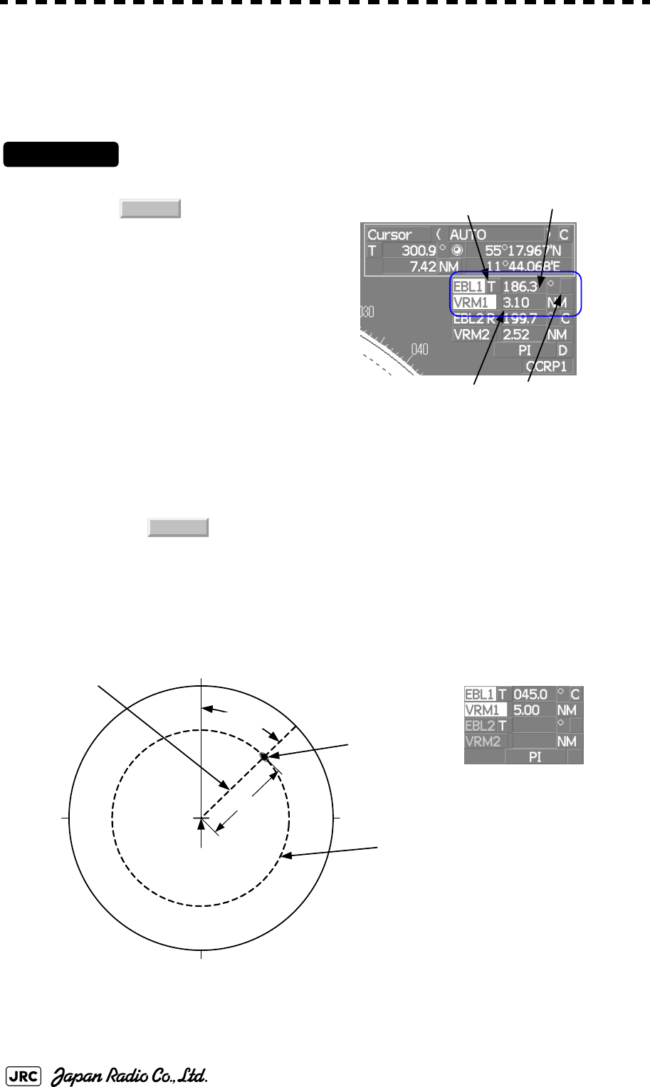
4-20
JMA-9100 Instruction Manual > 4.MEASUREMENT OF RANGE AND BEARING > 4.2 MEASUREMENT OF RANGE AND BEARING
4.2.2 Measurement with Electronic Bearing Line and Variable
Range Marker [EBL] [VRM]
Procedures
1) Press the [EBL1] key.
The (located at the upper
right of the display) will be
highlighted, and EBL1 will be
shown with a dotted line on the PPI
display.
2) Move the EBL1 to the
target by turning the [EBL]
dial.
The EBL1 bearing will be shown in
the EBL1 bearing (located at the
upper right of the display). The EBL1 bearing is the bearing of the target.
3) Press the [VRM1] key.
The (located at the upper right of the display) will be highlighted, and VRM1
will be shown with a dotted line on the PPI display.
4) Move the VRM1 to the target by turning the [VRM] dial.
The range of VRM1 from the own ship's position will be shown in the VRM1 range located
at the upper right of the display.
EBL1 adjustment
VRM1 adjustment
EBL1 numeric value indication
true / relative switching
EBL1 starting point
mode switching
EBL1
VRM1
Target
EBL1
180
0
90270
VRM1
5.00NM
Bearing and range from the
own ship’s position to target in this figure:
True bearing 45.0 °
Range 5.00 NM
45.0°
Own ship’s position
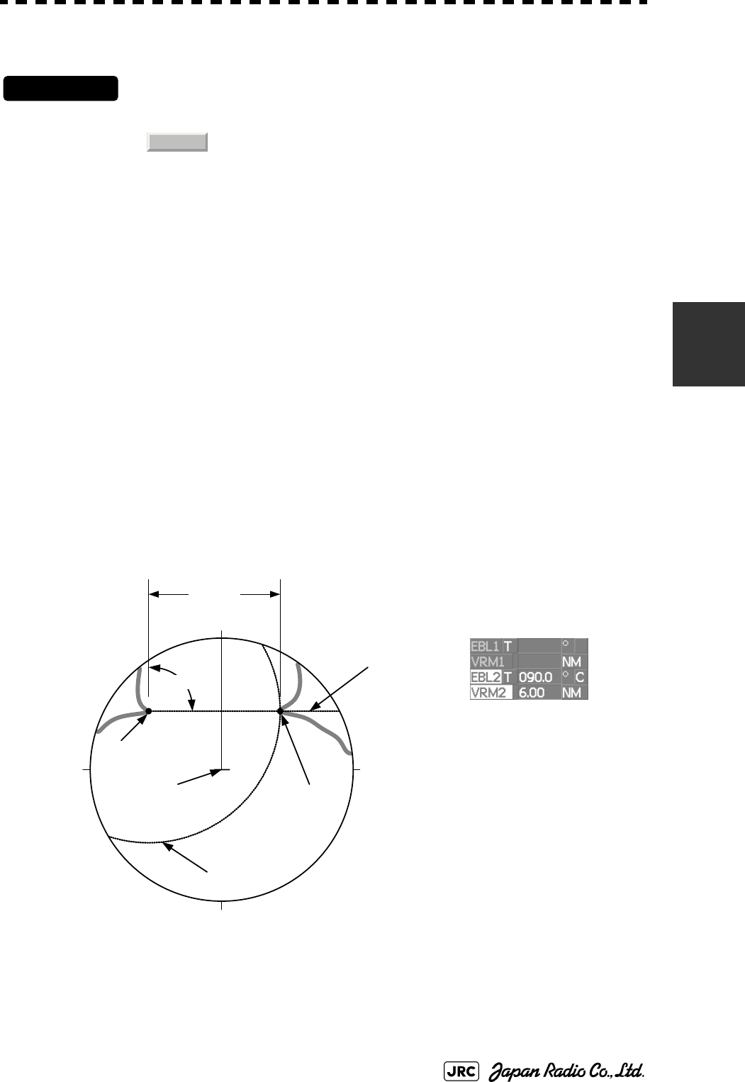
JMA-9100 Instruction Manual > 4.MEASUREMENT OF RANGE AND BEARING > 4.2 MEASUREMENT OF RANGE AND BEARING
4-21
4
4.2.3 Measurement with Two Arbitrary Points
Procedures
1) Press the [EBL2] key.
The ( located at the upper right of the display) will be highlighted, and EBL2
will be shown on the PPI display.
2) Press the [EBL] dial to select C for the EBL2 starting point mode
switching located at the upper right of the display.
3) Put the cursor on the point A of the two points between which
measurement is made, and left-click.
Refer to the figure below.
4) Move the EBL2 to the other point B by turning the [EBL] dial.
5) Press the [VRM2] key.
When VRM2 is selected, ● (intersection marker) will appear on the dotted line of EBL2.
6) Move the intersection marker on the dotted line to point B by
turning the [VRM] dial.
The range and bearing between the two points will be shown in the VRM2 range and EBL2
bearing (located at the upper right of display).
Similarly, EBL1 can also be used for measuring the bearing and range between
two points. In this case, perform the above procedure reading EBL2 as EBL1 and
VRM2 as VRM1.
EBL2
Cape
EBL2
90.0°
180
0
90270
VRM2
6.00NM
Bearing and range between points
A and B in this figure:
True bearing 90.0 °
Range 6.00 NM
Cape
AB
Own ship’s position

4-22
JMA-9100 Instruction Manual > 4.MEASUREMENT OF RANGE AND BEARING > 4.2 MEASUREMENT OF RANGE AND BEARING

OPERATION OF TARGET TRACKING AND AIS
5.1 PREPARATION ......................................................................................5-1
5.1.1 Collision Avoidance ........................................................................5-2
5.1.2 Definitions of Symbols ...................................................................5-5
5.1.3 Radar Display ..................................................................................5-8
5.1.4 Cursor Modes (Cursor) .................................................................5-10
5.1.5 Setting Collision Decision Criteria ..............................................5-12
5.1.6 Setting Vectors (Vector Time) ......................................................5-13
5.1.7 Setting the GPS antenna location ................................................5-13
5.2 TARGET TRACKING OPERATION .....................................................5-14
5.2.1 Acquiring Target [ACQ] ................................................................5-14
5.2.2 Canceling Unwanted Tracked Targets [ACQ CANCEL] .............5-16
5.2.3 Tracked Target Data Display [TGT DATA] ..................................5-17
5.2.4 Displaying Target ID No.(Target Number Display) .....................5-18
5.2.5 Adding Tracked Target ID Name (Name) .....................................5-19
5.2.6 Reference Target (Reference) ......................................................5-20
5.2.7 Operation Test (TT Test Menu) ...................................................5-21
5.3 AIS OPERATION ..................................................................................5-26
SECTION 5
OPERATION OF TARGET TRACKING
AND AIS
5.3.1 Restrictions ....................................................................................5-26
5.3.2 Setting AIS Display Function (AIS Function) ..............................5-26
5.3.3 Activate AIS Targets (Activate AIS) .............................................5-27
5.3.4 Deactivate AIS Targets (Deactivate AIS) .....................................5-27
5.3.5 Displaying AIS Information [TGT DATA] .....................................5-28
5.3.6 Displaying Target ID No. (Target Number Display) ....................5-31
5.3.7 Setting AIS Filter (AIS Filter Setting) ...........................................5-32
5.3.8 Conditions for Deciding AIS Target to be Lost ..........................5-35
5.3.9 Setting Conditions for AIS Alarm (AIS Alarm Setting) ...............5-36
5.4 DECISION OF TARGETS AS IDENTICAL (Association) ...................5-37
5.4.1 Setting of Function to Decide Targets as Identical (Association) .....5-37
5.4.2 Setting of Conditions for Deciding AIS and Tracked Targets as
Identical (Association Setting) .....................................................5-37
5.4.3 Types of Decision Conditions to be Set ......................................5-38
5.5 ALARM DISPLAY .................................................................................5-39
5.5.1 CPA / TCPA Alarm .........................................................................5-40
5.5.2 Alarm for New Target Acquired in Automatic Acquisition Zone
(New Target) ...................................................................................5-41
5.5.3 Lost Target Alarm (Lost) ...............................................................5-41
5.5.4 Gyro Set Alarm ..............................................................................5-42
5.6 TRACK FUNCTION ..............................................................................5-43
5.6.1 Past Position (Past POSN) ...........................................................5-43
5.6.2 Target Ship's Tracks (Target Track) ............................................5-44
5.7 TRIAL MANEUVERING (Trial Maneuver) ..........................5-53
5.7.1 Trial Maneuvering in the True Vector Mode ................................5-54
5.7.2 Trial Maneuvering in the Relative Vector Mode ..........................5-55
5.7.3 Operation of Trial Maneuvering Function ...................................5-56

JMA-9100 Instruction Manual > 5.OPERATION OF TARGET TRACKING AND AIS > 5.1 PREPARATION
5-1
5
5.1 PREPARATION
This section explains the features of the target tracking and AIS functions, and the
initial setting for using each function.
Target Tracking Function
The target tracking function calculates the course and speed of a target by
automatically tracking the target's move.
The target tracking function enables the automatic acquisition of targets by using
the automatic acquisition zone function.
The target tracking function also enables the simulation of the ship maneuvering
method to avoid collisions by using the trial maneuver function.
•There are the following limitations on use of the target acquisition and target
tracking functions.
[I] Resolution between adjacent targets and swapping during automatic target
tracking
Depending on the particular distance and echo size, resolution between adjacent
targets during automatic target tracking usually ranges somewhere between 0.03 to
0.05 NM. If multiple targets approach each other, resolution will become about 0.05 NM
and this may cause the system to regard them as one target and thus to swap them or
lose part of them. Such swapping or less of targets may also occur if the picture of the
target being tracked is affected by rain/snow clutter returns or sea clutter returns or
moves very close to land.
[II] Intensity of echoes and the target tracking function
The intensity of echoes and the tracking function have a correlationship, and thus the
target will be lost if no echoes are detected during six scans in succession. If a lost
target exists, therefore, radar gain must be increased to support detection of the target.
If, however, radar gain is increased too significantly, sea clutter returns or other noise
may be erroneously detected and tracked as a target, and resultingly, a false alarm
may be issued.
[III]Adverse effects of error sources on automatic tracking
To execute accurate tracking, it becomes necessary first to appropriately
adjust the [GAIN], [SEA] and [RAIN] dials of the radar so that the target
to be acquired and tracked id clearly displayed on the radar display.
Inappropriate settings of these adjustments reduce the reliability /
accuracy of automatic tracking.
Attention
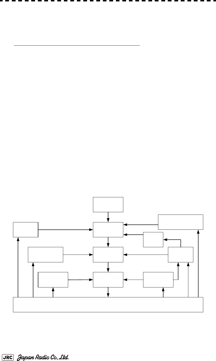
5-2
JMA-9100 Instruction Manual > 5.OPERATION OF TARGET TRACKING AND AIS > 5.1 PREPARATION
If the mode is ground stabilization, SOG/COG used for own ship's information in
target tracking. If the mode is sea stabilization, SPD (speed through the water) /
HDG (heading) used for own ship's information in target tracking.
AIS (Automatic Identification System) function
The AIS function shows the target’s information on the radar display, using
other ship's information sent out from the AIS unit.
5.1.1 Collision Avoidance
5.1.1.1 Problems of Collision Avoidance in Navigation
Marine collision avoidance is one of the problems that have been recognized from
of old. Now, it will be described briefly who the collision avoidance is positioned
among the navigational aid problems.
The navigation pattern of all mobile craft constitutes a system with some closed
loops regardless of the media through which the mobile craft travels, whether air,
water, the boundary between air and water, or space. This pattern consists of two
closed loops in principle, one of which is a collision with another mobile craft and
the other is a loop of finding a right and safe way to reach a predeterminate
destination. Fig. 5-1 shows the conceptual diagram of navigation pattern by MR.
E.W. Anderson. The closed loop of collision avoidance is shown on the left side
and the closed loop of finding a right course on the right side.
Fig 5-1: Navigation Pattern
Destination
Mancuver
Cource and
speed
Course
Ship traveling in controlled condition
Insrument or
judgement
Control
loop
Compass
and log
Caluculati
on
Fixing by radio wave ,
visual and celestial
observation
Judgement
Visual and radio
watch
Traffic rule
Cllision
avoidance loop
Vessel’s Spacing loop
Collision avoidance Decision of cource
Guide loop
Dead
reckoning
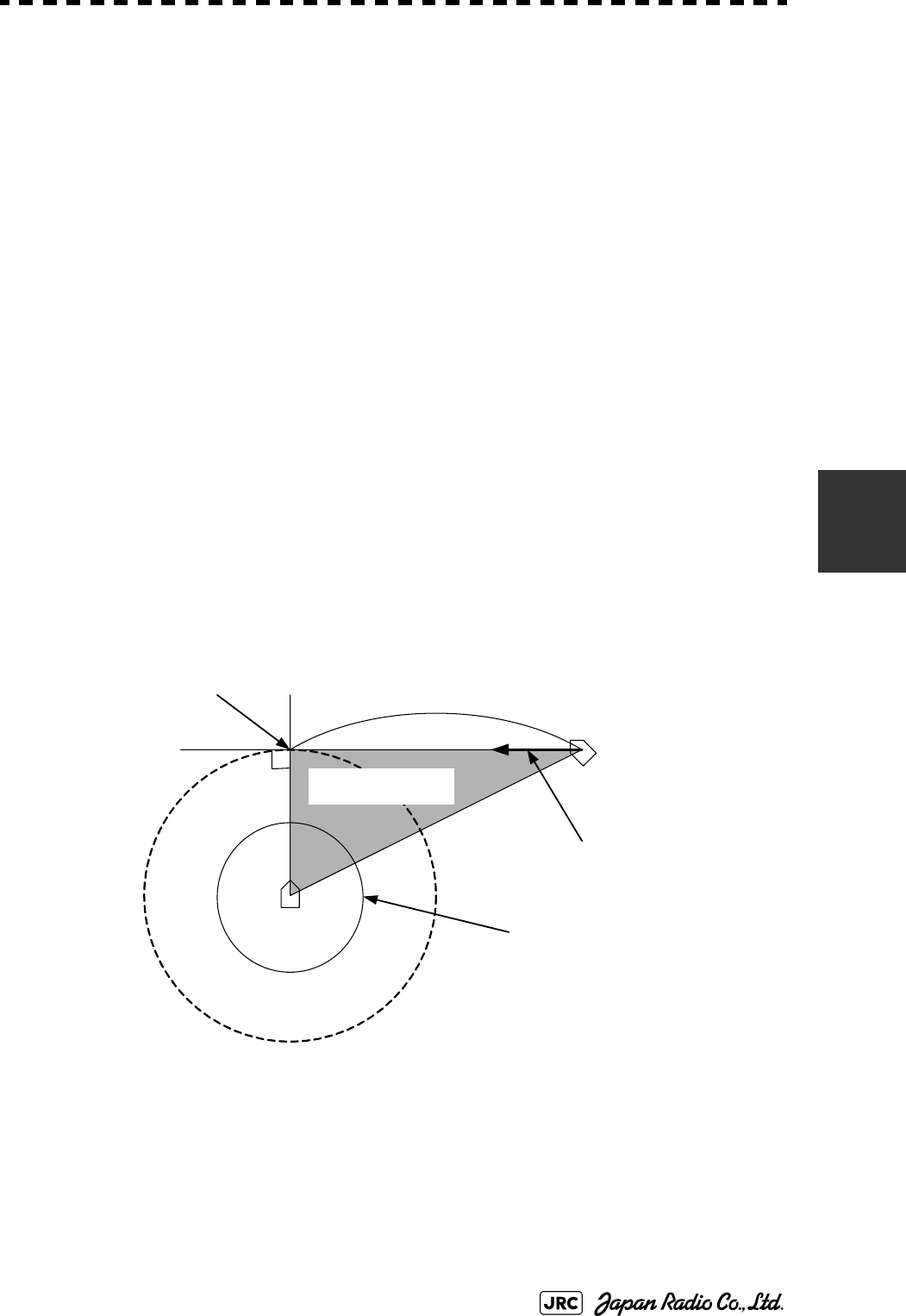
JMA-9100 Instruction Manual > 5.OPERATION OF TARGET TRACKING AND AIS > 5.1 PREPARATION
5-3
5
5.1.1.2 Marine Accidents and Collisions
Among marine accidents, collision accidents have been highlighted as the
tonnages and speeds of ships become higher along with the increase in traffic at
sea. If a tanker carrying dangerous articles such as crude oil collides with any
other vessel, then not only the vessels involved with the accident but other vessels
in the vicinity, port facilities, inhabitants in the coastal area as well as marine
resources may also suffer immeasurable damages and troubles. Collision
accidents have a high percentage of the marine accidents that have occurred in
recent years. To cope with these problems, any effective measures are needed and
some equipment to achieve collision avoidance requirements have been developed
at rapid strides.
5.1.1.3 Basic Concept of Collision Avoidance
There are two aspects in collision avoidance: collision prediction and avoidance.
Collision prediction is to predict that two or more vessels will happen to occupy
the same point at the same time, while collision avoidance is to maneuver vessels
not to occupy the same point at the same time.
In practical operation of vessels, a spot of collision has to be deemed to be a single
point but a closed zone. This closed zone is conceptually defined as a CPA
(Closest Point of Approach). In collision prediction, the time to be taken until a
ship reaches the CPA is defined as a TCPA (Time to CPA).
Fig. 5-2 shows a diagram caked "Collision Triangle".
Fig 5-2: Collision Triangle
Own
ship
CPA TCPA(Time to CPA)
Target
vessel
CPA ring
Relative vector
Collision triangle
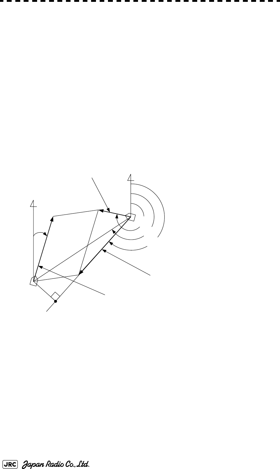
5-4
JMA-9100 Instruction Manual > 5.OPERATION OF TARGET TRACKING AND AIS > 5.1 PREPARATION
5.1.1.4 Relative Vector and True Vector
From two points of view, collision prediction and avoidance, it is necessary to
obtain the relative vector of other ship for prediction and the true vector of other
ship for collision avoidance in order to grasp other ship’s aspect. The
relationship between the relative vector and true vector is shown in Fig. 5-3.
Both rough CPA and TCPA can be obtained easily from the relative speed vector
of other ship. This method has an advantage that the risks of collision with all
other ships within the radar range can be seen at a glance. On the other hand, the
course and speed of other ship can easily be obtained from its true speed vector,
enabling other ship’s aspect to be seen at a glance. Thus, the aspects of other
ships (transverse, outsail, parallel run, reverse run, etc. ) as described in the act of
prevention of collision at sea can be readily grasped. If there is a risk of collision
with other ship, the operator can determine which rule to be applied and how to
operate own ship.
Fig 5-3: Relative Vector and True vector
5.1.1.5 Radar and Collision Avoidance
Radar is still playing an important roll for collision prevention and positioning.
A plotter is used to further enhance the radar functionality. The plotter is capable
of plotting other positions of other ships in 3 to 6 minute intervals to monitor their
movement. The plots of other ships represent their tracks relative to own ship, and
it is shown whether there is a risk of collision, namely CPA and TCPA can be
obtained. This method using a plotter is fairly effective, but the number of target
ship, which is manually plotted, is limited and it takes several minutes to measure
those.
N
θ
T
θ
R
θ
A
θ
O
V
o
V
R
V
T
V
O
: Own ship's speed
θ
O
: Own ship's course
V
T
: Other ship's true speed
θ
T
: Target ship's true course
V
R
: Target ship's relative speed
θ
R
: Target ship's relative course
θ
A
: Aspect
Relative vector
Target ship true vector
N
CPA
Own ship true vector
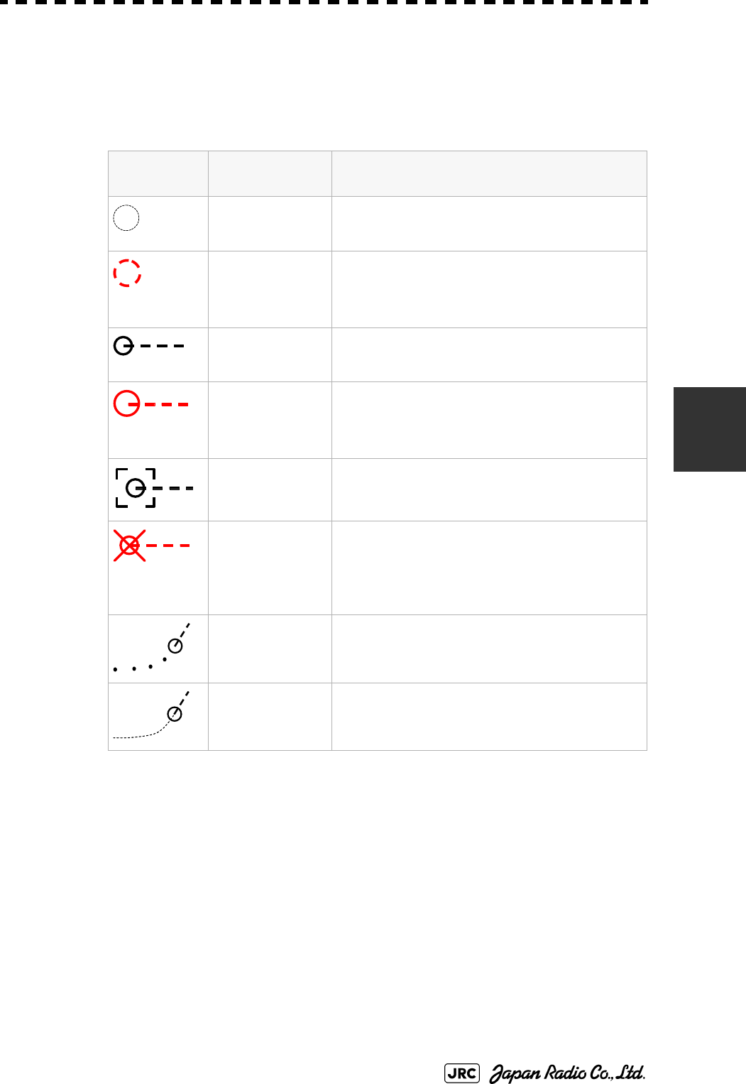
JMA-9100 Instruction Manual > 5.OPERATION OF TARGET TRACKING AND AIS > 5.1 PREPARATION
5-5
5
5.1.2 Definitions of Symbols
5.1.2.1 Types and Definitions of Target Tracking Symbols
Vector/
Symbol
Definition Remarks
Initial acquisition
target
This symbol is displayed until the vector is
displayed after target acquisition.
Target acquired in
automatic
acquisition zone
The alarm sounds.
The alarm message (New Target) turns red and
blinks.The symbol is red colored.
Tracked target
Dangerous target The alarm sounds.
The alarm message (CPA/TCPA) turns red and
blinks.The symbol turns red and enlarges.
Numeric
displayed target
When the numeric data is displayed, the target
symbol is enclosed in a square.
Lost target The alarm sounds.
The alarm message (Lost) turns red and
blinks.The symbol turns red, and indicates with
X mark.
Past position The past positions of an AIS target are displayed
as well as the target tracking symbol.
Target track The track of another ship as an AIS target is
displayed as well as the target tracking symbol.
12
12
12
12
12
12
12
12
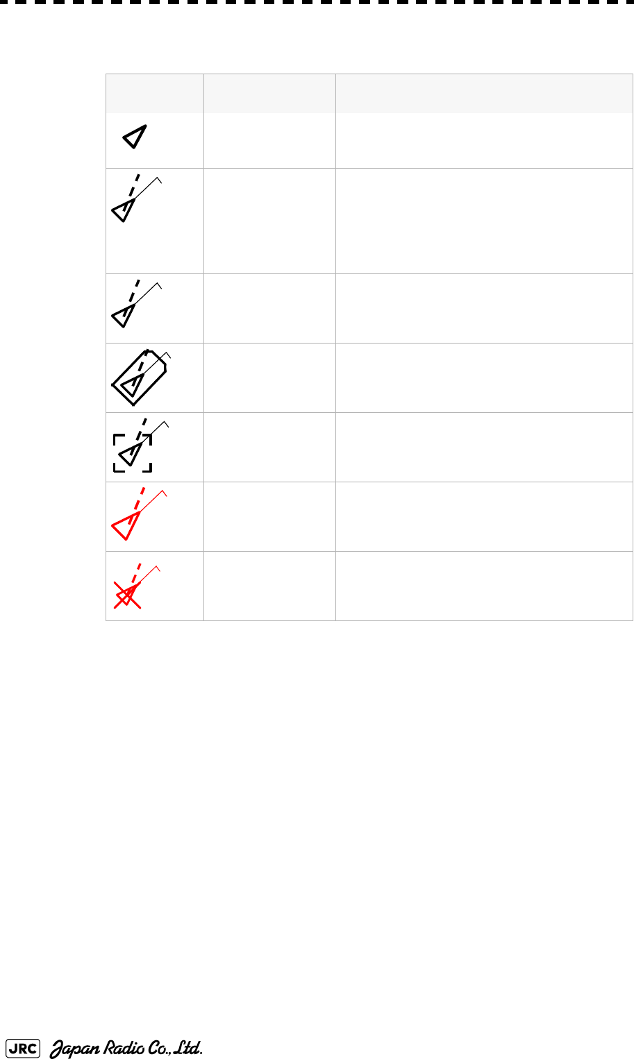
5-6
JMA-9100 Instruction Manual > 5.OPERATION OF TARGET TRACKING AND AIS > 5.1 PREPARATION
5.1.2.2 Types and Definitions of AIS Target Symbols
Up to 300 targets can be displayed in total of activated and sleeping AIS targets. Up to 100
activated AIS targets can be included in the total.
•If there are more AIS targets than the allowable maximum, they are displayed
in the following priority order:
•If the number of targets at the same priority level exceeds the allowable
maximum, they are displayed in the following priority order:
Vector/
Symbol
Definition Remarks
Sleeping target This symbol is displayed when received data is
valid.The direction of the triangle's vertex
indicates the target's bow or course.
Activated target The heading direction is displayed with a solid
line, and the course vector is displayed with a
dotted line. The line perpendicular to the
heading direction indicates the direction to
which the course is to be changed. This line
may not be displayed.
Target acquired in
automatic
acquisition zone
The alarm sounds.
The alarm message (New Target) turns red
and blinks.
Outline display The outlines of ships are displayed scaled
down.
Numeric displayed
target
When the numeric data is displayed, the target
symbol is enclosed in a square.
Dangerous target The alarm sounds.
The alarm message (CPA/TCPA) turns red
and blinks.The symbol turns red and enlarges.
Lost target The alarm sounds.
The symbol turns red, and indicates with X
mark.
1. Numeric displayed target
2. Target of which CPA / TCPA is lower than the set
value(Target as a dangerous ship for which an alarm
has occurred)
3. Target in automatic activation zone
4. Activated AIS target
5. Target inside AIS filter
6. Target outside AIS filter
1. Association target
AIS12
AIS12
AIS 12
AIS12
AIS12
AIS 12

JMA-9100 Instruction Manual > 5.OPERATION OF TARGET TRACKING AND AIS > 5.1 PREPARATION
5-7
5
The vector of an AIS target is to be displayed with a vector over ground or over
water, depending on the speed sensor setting and current offset setting. The type
of the currently displayed vector can be confirmed by viewing the setting of the
stable mode.
When the vector of an AIS target is displayed with a vector over water, the system
has converted the AIS target's vector over ground to the vector over water
according to the data received from the AIS and the own ship's information.
5.1.2.3 Types and Definitions of Association Target Symbols
When a tracked target and an AIS target are decided as identical, it is displayed
with either of the following symbols:
a. Setting of Tracked Target Symbol Display
This function switches the tracking target symbol display between on and
off.Even if the tracking target symbol display is turned off, the data is retained.
Procedures
1) Left-click the button in the Target Information located at the
upper right of the display.
The tracking target symbol display will be set to on or off.
2. Activated AIS target
3. Sleeping AIS target
When is displayed for
the stability mode (Upper left of
the display on page 2-3):
Vector over ground
When is displayed for
the stability mode (Upper left of
the display on page 2-3):
Vector over water
NOTE:
When the AIS target's symbol is activated but the vector is not
displayed, the following are probable causes of the trouble:
•COG/SOG is not yet input from the GPS.
•The selected speed sensor is malfunctioning.
Vector/
Symbol
Definition Remarks
Priority for tracked target
Association target
Priority for AIS target
Association target
GND
Sea
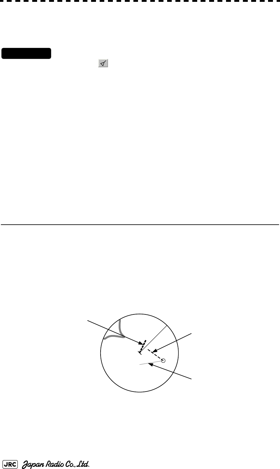
5-8
JMA-9100 Instruction Manual > 5.OPERATION OF TARGET TRACKING AND AIS > 5.1 PREPARATION
b. Setting of AIS Target Symbol Display
This function switches the AIS target symbol display between on and off.
Procedures
1) Left-click the button in the Target Information located at the
upper right of the display.
The AIS target symbol display will be set to on or off.
5.1.3 Radar Display
5.1.3.1 Vector Display
A vector to represent a target’s predicted position can be presented in the True
vector or Relative vector mode. In each mode, a vector length can be freely
changed for a time interval of 1 to 60 minutes.
To switch between the true vector mode and relative vector mode, press the [T/R
VECT] key.
5.1.3.2 Vector Mode Selection
[1] True Vector Mode
In the true vector mode, the direction of a target vector indicates the true course of
the target and its vector length is proportional to its speed.
In this mode, own ship's vector is displayed as shown Fig 5-4.
In this mode, the movements of other ships around own ship can be accurately and
easily monitored.
However, CPA Ring cannot appear in this mode.
Fig 5-4: True Vector
The relative vector is
not displayed
True vector
Own ship’s position HL