Japan Radio Co NKE1125 Marine Radar User Manual JMA 9100 series RADAR Instruction Manual
Japan Radio Co Ltd. Marine Radar JMA 9100 series RADAR Instruction Manual
Contents
- 1. Users Manual 1
- 2. Users Manual 2
- 3. Users Manual 3
Users Manual 2
JMA-9100 Instruction Manual > 5.OPERATION OF TARGET TRACKING AND AIS > 5.1 PREPARATION
5-9
5
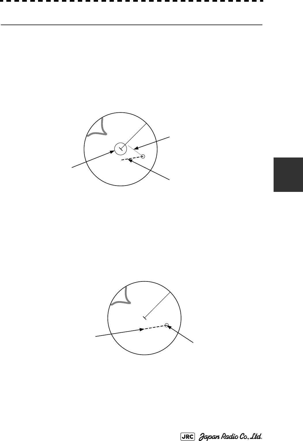
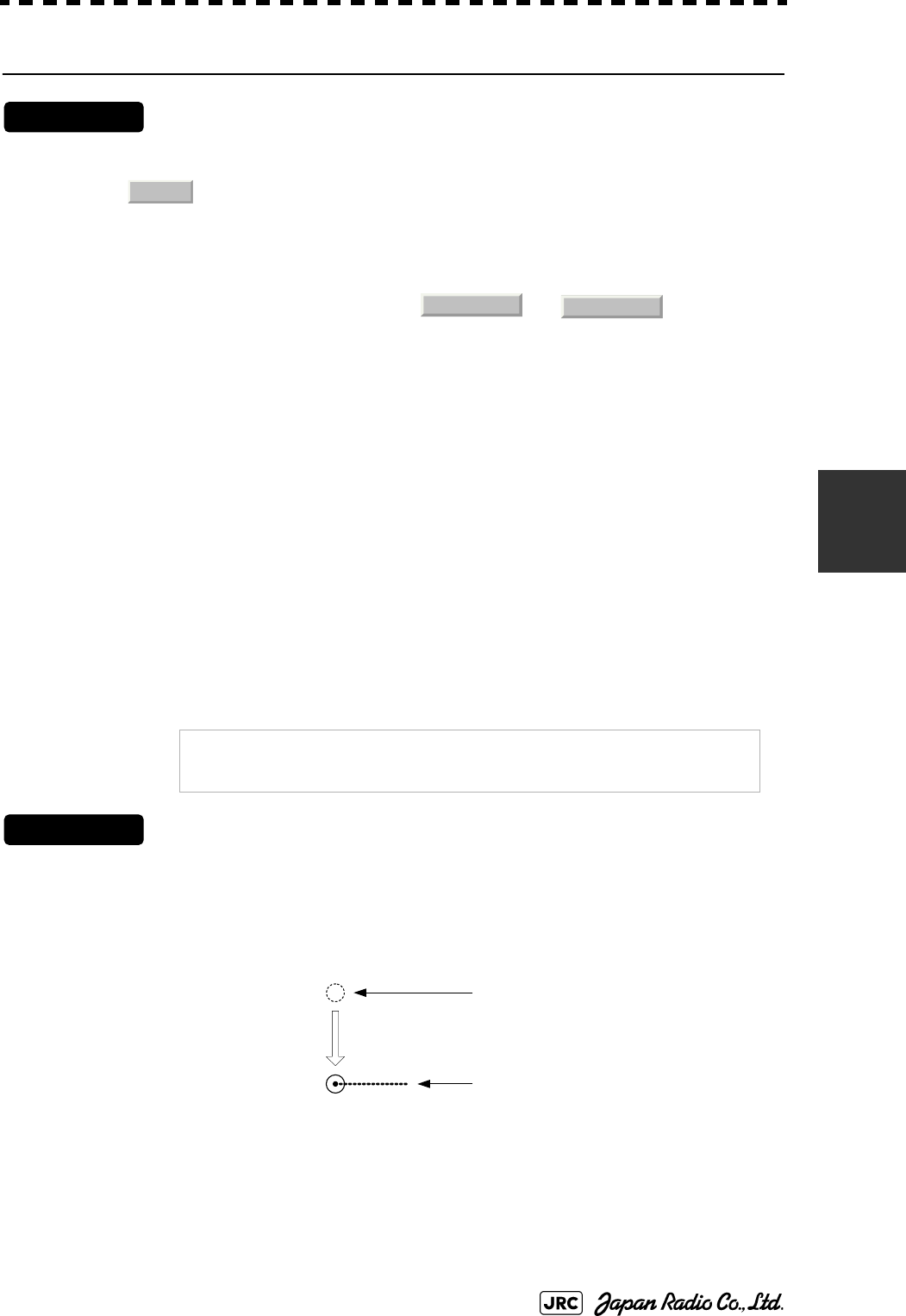
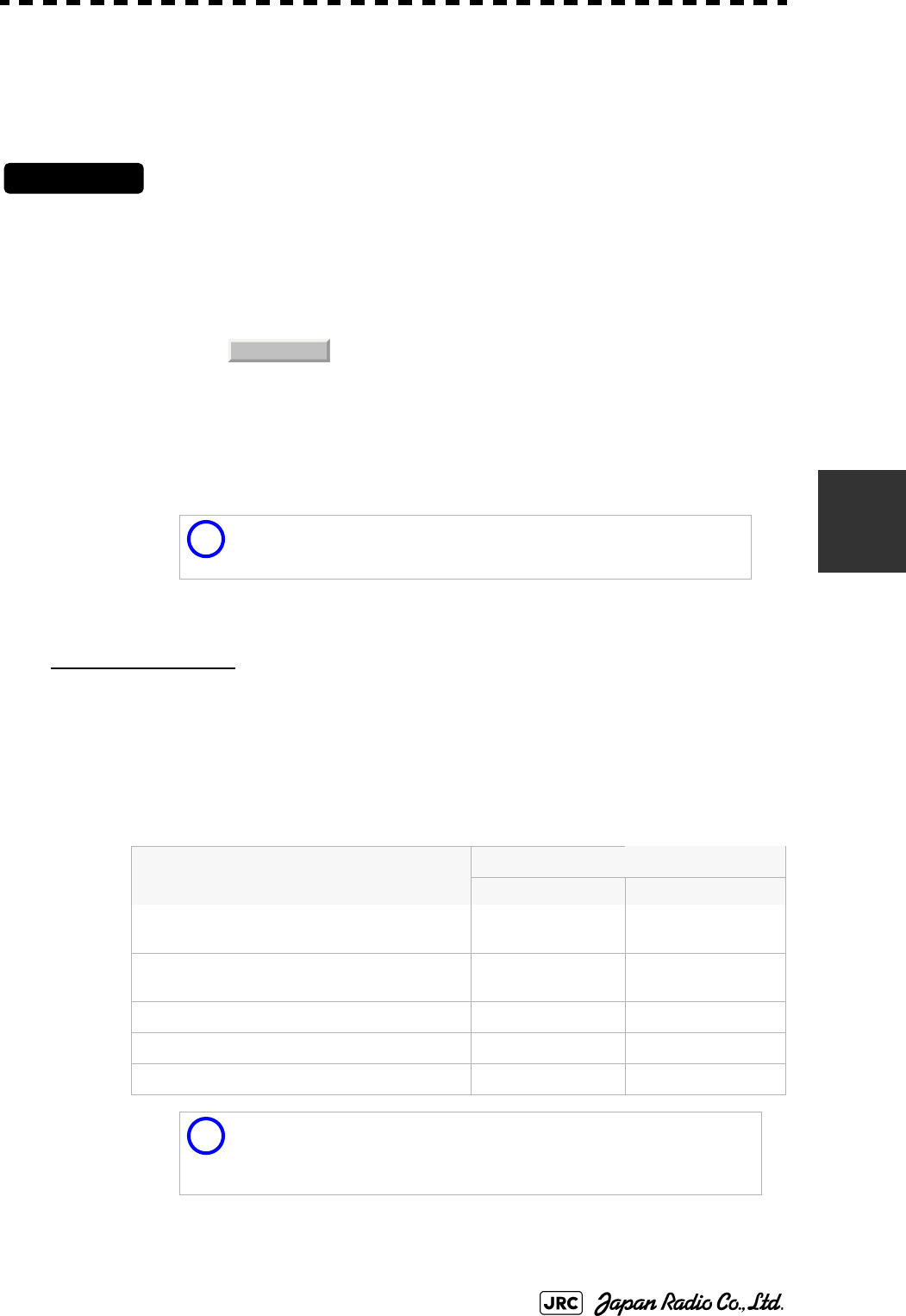
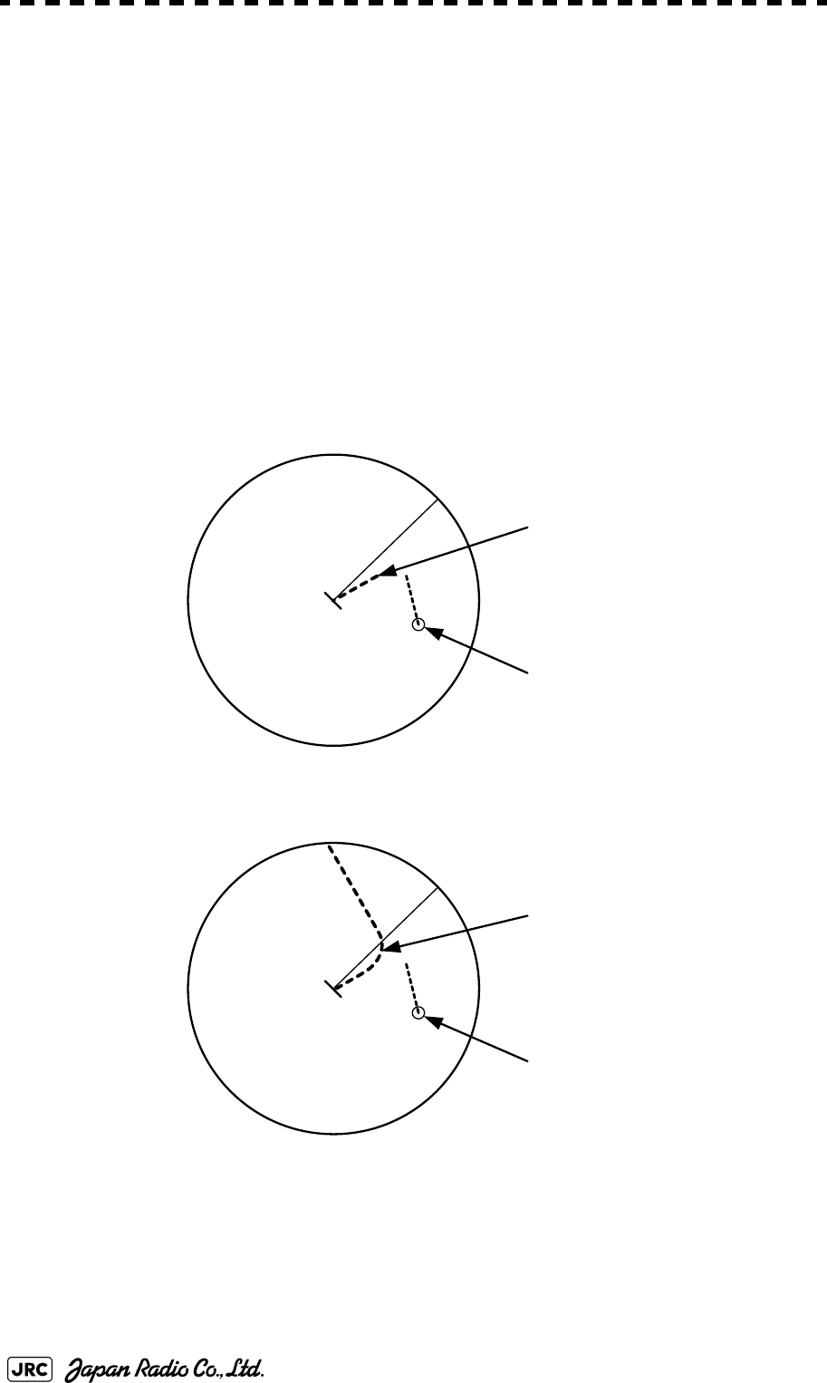
[2] Relative Vector Mode
The relative vector does not represent the true motion of the target, but its relative
relation with own ship. This means that a target with its relative vector directed to
own ship (passing through the CPA Limit ring) will be a dangerous target. In the
Relative Vector mode, it can be seen at a glance where the CPA Limit of the
dangerous target is.
Therefore, the True / Relative mode shall optionally be used for the purpose of
observation: the True vector mode for grasping the true aspect of a target, and the
Relative vector mode for grasping a target’s closest point of approach (CPA).
Fig 5-5: Relative Vector
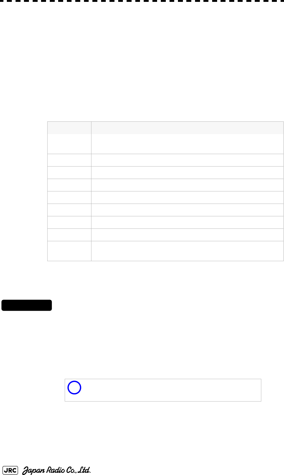
5.1.3.3 Vector Length (Vector Time)
The vector length of a target is proportional to its speed, and the vector time can
be switched in a range of 1 to 60 minutes.
The diagram below illustrates a vector length of a target for 6 minutes, and the tip
of the vector represents the target's position expected to reach 6 minutes later.
Fig 5-6: Vector Length
Refer to Section 5.1.6 "Setting Vectors (Vector Time)".
The true vector is
not displayed
Relative vector
CPA ring
HL
Current position
Future predicted position
(6 min later in this example)
HL
5-10
JMA-9100 Instruction Manual > 5.OPERATION OF TARGET TRACKING AND AIS > 5.1 PREPARATION
5.1.4 Cursor Modes (Cursor)
5.1.4.1 Types and Functions of Cursor Modes
The types of cursor modes are listed in the table below. To use the function of a
cursor mode, move the cursor onto the PPI object and left-click.
5.1.4.2 Change of Cursor Mode
Procedures
1) Left-click the Cursor button located at the upper right of the
display. Alternatively, on the PPI, right-click and select a desired
cursor mode from the list.
The selected cursor mode will be shown at the cursor mode (Upper right of the display on
page 2-4).
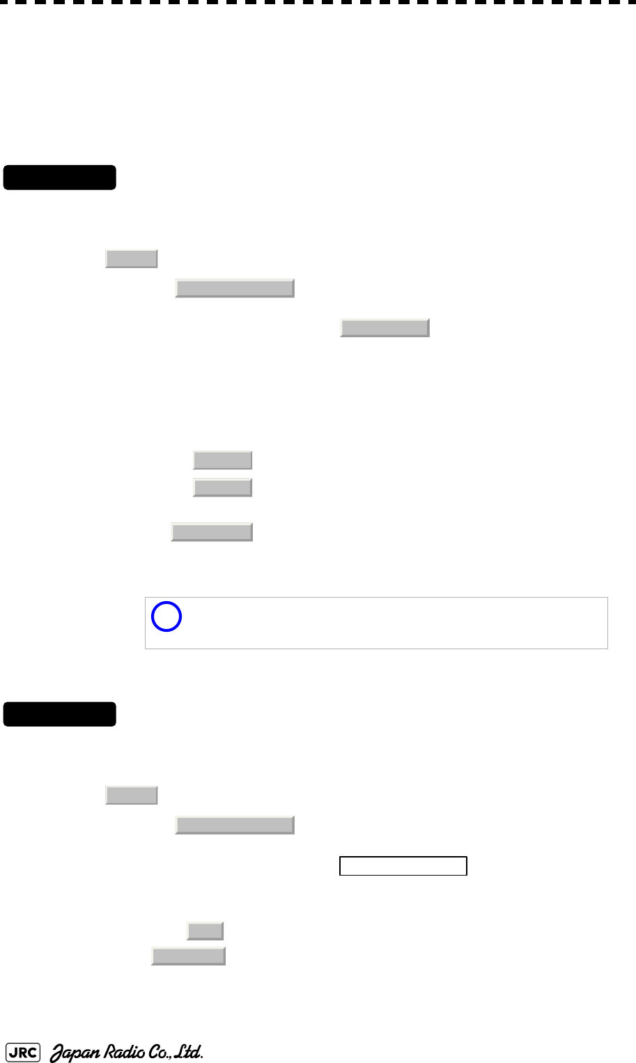
5.1.4.3 Operation of AUTO Mode
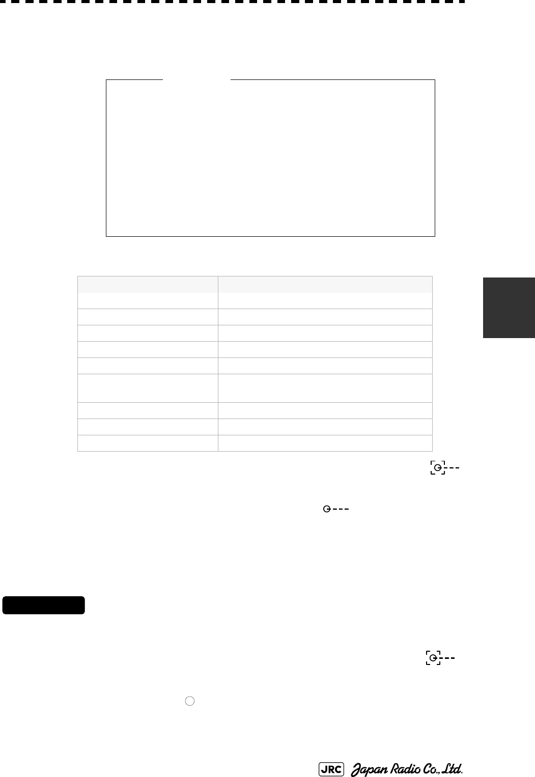
Mode Function
ACQ TT Enables the target tracking function to acquire a target in manual
mode.
ACT AIS Activates AIS targets, and sets a point filter.
TGT Data Displays the numeric data of a tracking target or AIS target.
CNCL TT Cancels a tracking target.
DEACT AIS Deactivates AIS target.
Data CNCL Hides the displayed numeric data of a tracked target or AIS target.
Mark Puts a temporary mark.
Property Displays the information of tracked targets, AIS targets, and marks.
AUTO Changes operation in accordance with the object at the cursor
position.
If the function of a selected cursor mode is not used for one
minute or more, the cursor mode is automatically changed to
AUTO .
i

JMA-9100 Instruction Manual > 5.OPERATION OF TARGET TRACKING AND AIS > 5.1 PREPARATION
5-11
5
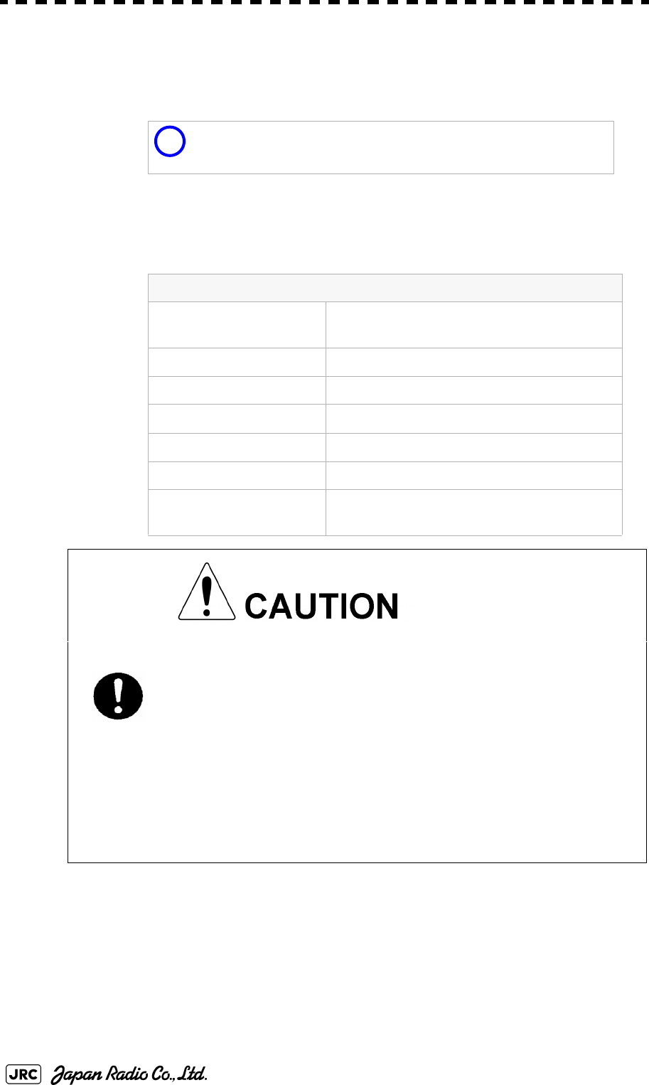
As shown below, the AUTO mode performs operation in accordance with the
object at the cursor position when left-clicked.
The AUTO mode permits to access that you want by intuitive operation.
Object at Cursor Position Operation
None Acquires a target.
EBL EBL operation.
VRM VRM operation.
Intersection point of EBL
and VRM
Performs EBL operation and VRM operation at
the same time.
Parallel index line Operates the parallel index line.
Tracked target Displays the numeric data of the tracked target.
Tracked target with
numeric data displayed
Hides the numeric data.
Sleeping AIS target Activates the AIS target.
Activated AIS target Displays the AIS target information.
AIS target with numeric
data displayed
Hides the AIS target information.
Automatic acquisition /
activation zone
Operates the automatic acquisition / activation
zone.
AIS filter Operates the AIS filter zone.
5-12
JMA-9100 Instruction Manual > 5.OPERATION OF TARGET TRACKING AND AIS > 5.1 PREPARATION
5.1.5 Setting Collision Decision Criteria
5.1.5.1 Input of CPA Limit
Procedures
1) Left-click the CPA limit setting button in the Target Information
located at the upper right of the display.
The CPA Limit value input screen will appear.
2) Enter the value to be set as a CPA limit.
For inputs to the value input screen, refer to Section 3.3.4 "Operation on Numeric Value,
Latitude / Longitude and Character Input menu".
5.1.5.2 Input of TCPA Limit
Procedures
1) Left-click the TCPA limit setting button in the Target Information
located at the upper right of the display.
The TCPA Limit value input screen will appear.
2) Enter the value to be set as a TCPA limit.
For inputs to the value input screen, refer to Section 3.3.4 "Operation on Numeric Value,
Latitude / Longitude and Character Input menu".
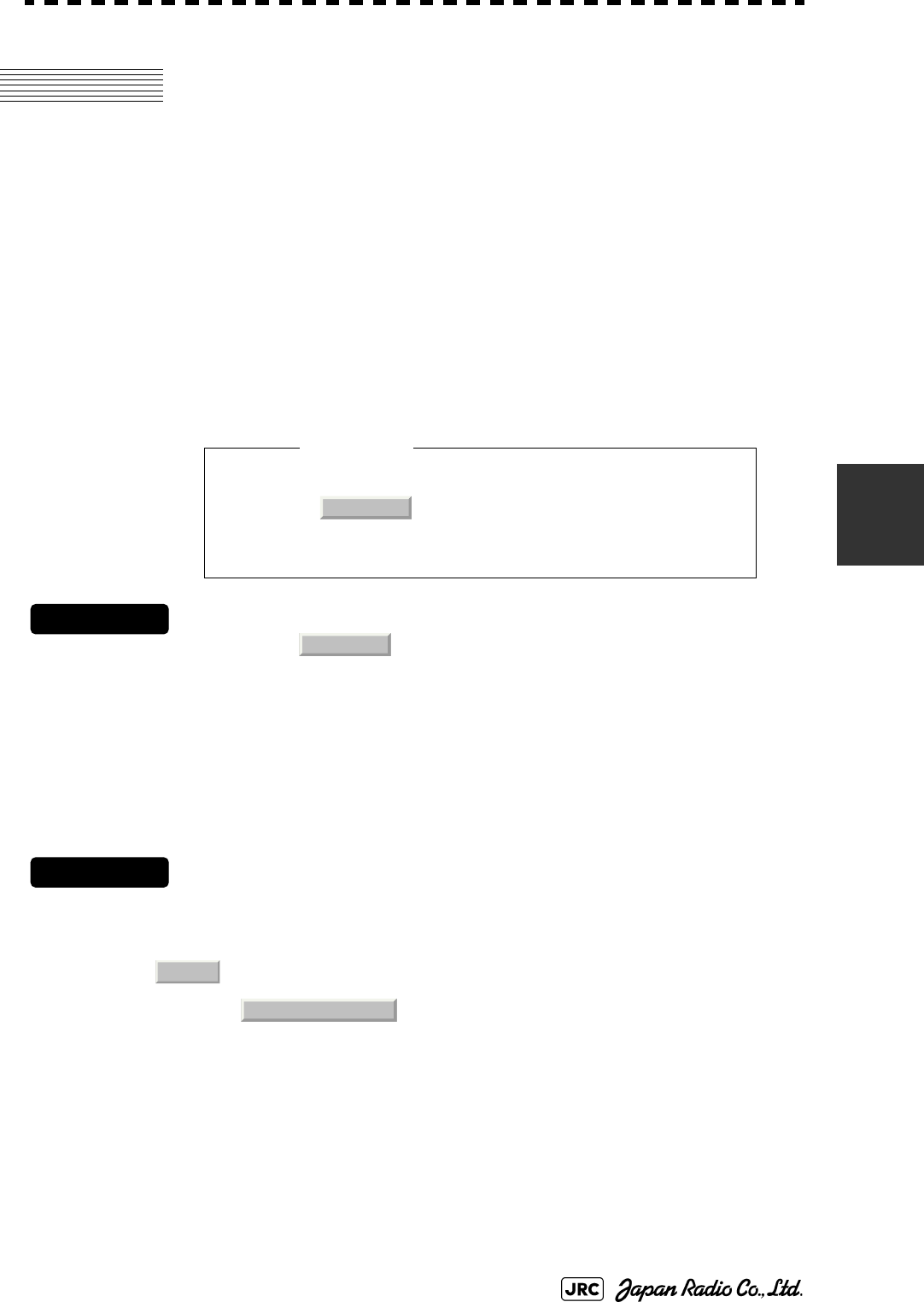
5.1.5.3 Setting CPA Ring (CPA Ring)
While the distance of the specified CPA Limit value is used as the radius, the CPA
ring is displayed with a red circle.
Procedures
1) Left-click the CPA Ring button located at the lower right of the
display.
The CPA ring will be displayed.
• Set the optimum values of collision decision
conditions, depending upon vessel type, water area,
weather and oceanographic conditions. (For the
relations between those conditions and alarms, refer
to Section 5.5 "ALARM DISPLAY". )
NOTE:
The CPA ring is not displayed when the true vector mode is
selected.
Attention

JMA-9100 Instruction Manual > 5.OPERATION OF TARGET TRACKING AND AIS > 5.1 PREPARATION
5-13
5
5.1.6 Setting Vectors (Vector Time)
Vector time can be set in minutes in the range 1 to 60 min.
A true vector mode or relative vector mode can be selected.
5.1.6.1 Setting vector time on the display (Vector)
Procedures
1) Left-click the target vector time setting button in the Target
Information located at the lower right of the display.
The Vector Time value input screen will appear.
2) Enter the value to be set as vector time.
For inputs to the value input screen, refer to Section 3.3.4 "Operation on Numeric Value,
Latitude / Longitude and Character Input menu".
5.1.6.2 Setting vector mode [T/R VECT]
Procedures
1) Press the [T/R VECT] key.
The current vector mode (true vector) or (relative vector) will be displayed in the
target vector display true / relative switching in Target Information located at the upper right
of the display.
5.1.7 Setting the GPS antenna location
Set the GPS antenna location. Set offset ranges in longitudinal direction and
latitudinal direction from the own ship's reference position.
For the setting procedure, refer to Section 7.1.9 "Setting of CCRP (CCRP
Setting)".
• If offset ranges are not set correctly, AIS symbols
and radar echoes may be displayed shifted.
• When offset ranges are set, latitude and longitude
data received from the GPS is offset, and the offset
data is displayed as the latitude and longitude of
own ship’s position.
TR
Attention
5-14
JMA-9100 Instruction Manual > 5.OPERATION OF TARGET TRACKING AND AIS > 5.2 TARGET TRACKING OPERATION
5.2 TARGET TRACKING OPERATION
This section explains how to use the target tracking function.
The target tracking function automatically tracks a target, and displays the target's
course and speed as vectors. The target tracking function calculates CPA and
TCPA, and issues an alarm as needed.
The tracking data is erased from memory when the power is turned off or during
transmission standby.
5.2.1 Acquiring Target [ACQ]
Target acquisition can be performed on two modes, Automatic and Manual, and
both modes can be used at the same time.
5.2.1.1 Automatic acquisition
[1] Turning On / Off the automatic acquisition and AIS activation (AZ Menu)
Procedures
1) Open the AZ menu by following menu operations.
The AZ Menu will appear.
2) Left-click the item button of or .
The acquisition / activation zone 1 (AZ1) or acquisition / activation zone 2 (AZ2) will be set
to on or off.
NOTE:
If the number of targets being tracked has reached the
allowable maximum and other targets (not being tracked) go
into the acquisition/activation zone, automatically acquired
targets are canceled in ascending order of danger.
The position of the scanner shall be at the centre of the azimuth
or range in the acquisition/activation zone.
:The acquisition / activation zone is turned on. The mark
and target ID number are put to an acquired target and
move with the target. The vectors are displayed within 1
minute. AIS targets are activated.
:The acquisition/activation zone is turned off. The
acquisition/activation zone will disappear from the radar
display, but the system continues to track the acquired
target. The activated AIS targets remain activate.
AZ
1. AZ1 2. AZ2
On
12
Off
JMA-9100 Instruction Manual > 5.OPERATION OF TARGET TRACKING AND AIS > 5.2 TARGET TRACKING OPERATION
5-15
5
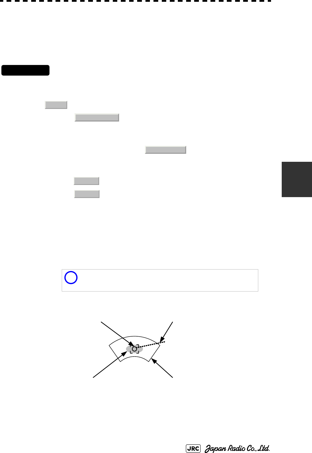
[2] Creating the automatic acquisition and AIS activation Zone (Make AZ)
Procedures
1) Open the AZ menu by following menu operations.
=捕捉・活性化メニュー (AZ Menu)が開きます。
2) Left-click the item button of or .
The range setting of the acquisition / activation zone 1 (AZ1) or acquisition / activation zone
2 (AZ2) will be started.
3) Set the starting azimuth and range by turning the [EBL] dial and
[VRM] dial, and left-click.
4) Set the ending azimuth and range by turning the [EBL] dial and
[VRM] dial, and left-click.
The acquisition / activation zone will be determined.
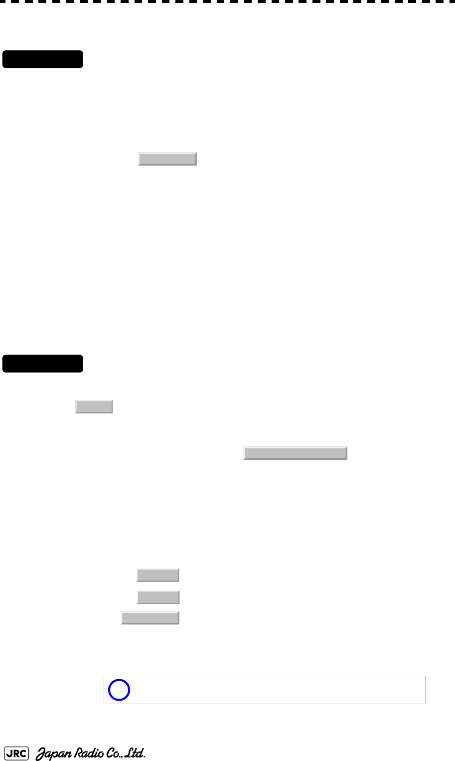
5.2.1.2 Manual Acquisition [ACQ MANUAL]
Procedures
1) Move the cursor onto the target to be acquired, and press the
[ACQ MANUAL] key.
The target will be acquired and the initial acquisition symbol will be displayed.
The vector will be displayed within one minute.
To perform operation only in the manual acquisition mode without automatic acquisition/
activation, turn off the automatic acquisition/activation function.
NOTE:
If more targets are acquired manually in the condition that the
maximum number of targets are under tracking, the targets
cannot acquired.
AZ
3. Make AZ1
4. Make AZ2
Target manually acquired .
The initial acquisition symbol is displayed .
Target that has passed for 1 min.
The acquisition symbol and vector are displayed .

5-16
JMA-9100 Instruction Manual > 5.OPERATION OF TARGET TRACKING AND AIS > 5.2 TARGET TRACKING OPERATION
[1] Use of Automatic and Manual Acquisition Modes
Use the manual acquisition mode while the automatic acquisition mode is on.
Manually acquire the target to which particular attention should be paid, and get
the other targets automatically acquired. If a new target appears exceeding the
maximum number of targets, the manually acquired target is displayed even in the
background until it gets out of the display. However, automatically acquired
targets are canceled starting far distance from own ship.
5.2.2 Canceling Unwanted Tracked Targets [ACQ CANCEL]
Unwanted tracked targets can be canceled one by one in the following cases:
•Tracking is no longer necessary for targets with which vectors/symbols are
displayed after being acquired and tracked.
•The number of vectors on the radar display needs to be reduced for easy
observation.
When targets are to be re-acquired from the beginning, all the current vectors can
also be canceled.
5.2.2.1 Canceling targets one by one [ACQ CANCEL]
Procedures
1) Put the cursor on the tracked target to the desired for canceling
target, and press the [ACQ CANCEL] key.
The vectors and symbols of the tracked targets will disappear, and only the radar video
remain.
5.2.2.2 Canceling all targets collectively [ACQ CANCEL]
Procedures
1) Press the [ACQ CANCEL] key for 5 seconds.
The vectors and symbols of all the targets will disappear, and only the radar videos remain.
NOTE:
When all the targets have been canceled, the system stops
tracking them. Thus, you need to re-acquire targets in manual
or automatic acquisition mode. Do not cancel all the targets
unless otherwise required.
JMA-9100 Instruction Manual > 5.OPERATION OF TARGET TRACKING AND AIS > 5.2 TARGET TRACKING OPERATION
5-17
5
5.2.3 Tracked Target Data Display [TGT DATA]
5.2.3.1 Type of Data Display (Target Information)
The target for which its numeric data is displayed is marked with a symbol
to distinguish from other targets.
If a target's data is displayed, but without the symbol , such a target exists
outside the currently displayed radar display.
5.2.3.2 Method of Displaying Numeric Data [TGT DATA]
Procedures
1) Put the cursor on the tracked target for which numeric data is to
be displayed, and press the [TGT DATA] key.
Then, the data of the designated target will appear, it will be marked with a symbol .
The target data will remain on the radar display until the target is lost and its vector
disappears, or until another target is designated.
If a target with the mark is designated, only its true bearing and range will appear until
its vector appears.
When a target or own ship changes its course, or
when a new target is acquired, its vector may not
reach a given level of accuracy until 3 minutes or
more has passed after such course change or target
acquisition.
Even if 3 minutes or more has passed, the vector
may include an error depending upon the tracking
conditions.
Target Data
Target identification (TT ID) ID number of the target
True bearing(BRG) 0.1° unit
Range 0.01NM unti
Cource 0.1° unit
Speed 0.1knot unit
Closest point of approach
(CPA)
0.01NM unit
Time to CPA (TCPA) 0.1min unit
Bow crossing range (BCR) 0.01NM unit
Bow crossing time (BCT) 0.1min unit
Attention
12
12
12
12
5-18
JMA-9100 Instruction Manual > 5.OPERATION OF TARGET TRACKING AND AIS > 5.2 TARGET TRACKING OPERATION
5.2.3.3 Cancellation of Numeric Data Display (CNCL Data)
Procedures
1) Put the cursor on the tracked target with which numeric data is
displayed, and right-click.
The cursor mode list will appear.
2) Left-click button.
The numeric value will disappear.
5.2.4 Displaying Target ID No.(Target Number Display)
A target ID number is a value displayed beside the acquisition symbol when a
target is acquired.
A target ID number 1 to 100 is assigned to each target in acquisition order. Once a
target ID number is assigned, it identifies the target until the target is lost or the
target acquisition is canceled.
Procedures
1) Open the TT Menu by following menu operation.
2) Left-click the item button of
Target Number Display will appear.
3) Press the [numeric] key corresponding to the display method to
be set.
If there are many tracking targets and their symbol display is confusing, set Target Number
Display to off to view the radar display easily.
: Displays target ID numbers.
: Hides target ID numbers.
: Displays target ID number with target track.
An ID number is always displayed for only targets with which
numeric data is displayed.
6. CNCL Data
TT
4. Target Number Display
On
Off
Target Track
i
JMA-9100 Instruction Manual > 5.OPERATION OF TARGET TRACKING AND AIS > 5.2 TARGET TRACKING OPERATION
5-19
5
5.2.5 Adding Tracked Target ID Name (Name)
The system can enter a name for each of tracking targets that have been acquired.
Procedures
1) Put the cursor on the tracked target, and right-click.
The cursor mode list will appear.
2) Left-click
The Property will appear.
3) Left-click the item button of .
The setting items for ship name (Name) will be displayed.
4) Select the input method.
5.2.5.1 Entering a new ship name (Input)
5) Input a new ship name.
Up to 8 characters can be input as a ship name.For the input method on the character input
screen, see Section 3.3.4.7 "Entering a character".
The input name by selecting is saved in Data Base .
5.2.5.2 Selecting one of previously input ship names (Data Base)
5) Press the [numeric] key corresponding to the ship name to be
selected.
The selected ship name will be entered.
:Selection of one of previously input ship
names.When this method is selected, a list of ship
names that have been input by selecting
will be displayed.
:Input of a new ship name. When this method is
selected, the ship name (Name) input window will
open.
i
Data Base can contain 30 ship names.
8. Property
1. Name
Data Base
Input
Input
Input

5-20
JMA-9100 Instruction Manual > 5.OPERATION OF TARGET TRACKING AND AIS > 5.2 TARGET TRACKING OPERATION
5.2.6 Reference Target (Reference)
The system can display the own ship's speed. To do so, it sets a reference target by
tracking a target for which ground fixed.
Procedures
1) Tracking a target for which ground fixed.
2) Put the cursor on the tracked target, and right-click.
The cursor mode list will appear.
• The reference target function is to be used if the own ship's
speed cannot be displayed normally due to trouble such as a
speed sensor malfunction. Do not use the reference target
function except in emergencies.
• If the speed or course of the own ship is changed or a new
reference target is set, the displayed speed may take 3 minutes or
more to reach the specified speed after the speed / course
change or the setting.
• Even after 3 minutes or more has passed, the speed may differ
from the specified speed depending on the tracking condition.
• If a large radar echo such as a land target is set as a reference
target, the vectors of the speed and other tracking targets will not
be displayed correctly and may cause an accident.
• If a sailing ship is set as a reference target, the vectors of the
speed and other tracking targets will not be displayed correctly
and may cause an accident.
• If the is selected for the speed sensor, the AIS function
cannot be turned on.
• If the reference target is lost or the target tracking function is
stopped, the speed sensor is placed in manual mode .
• The loss of a reference target may have a major impact on the
accuracy of the results for true speed and true course of the
target and that own speed will be degraded.
• The reference targets are only used for the calculation of true
speed.
Attention
REF .
MAN
JMA-9100 Instruction Manual > 5.OPERATION OF TARGET TRACKING AND AIS > 5.2 TARGET TRACKING OPERATION
5-21
5
3) Left-click
The Property will appear.
4) Left-click the item button of
The reference target function will be set to on or off.
5) Left-click the speed sensor switching button in the Own Ship
Information located at the upper right of the display, and select
.
The speed of own ship calculated from the reference target will be displayed.
When a reference target is set, the symbol display is changed to .
Only one target can be set as a reference target.When a new reference target is set, the
previously set reference target is canceled.
5.2.7 Operation Test (TT Test Menu)
The following functions are available for testing the target tracking function:
:A reference target is set.
:The reference target is canceled.
This function is provided to test if the target tracking
function is operating normally. Thus, do not use the
function except when you test the target tracking
function.
In particular, if the operation test mode is used during
navigation, pseudo targets appear on the radar display
and they are confused with actual targets.
Do not use the mode during navigation. Otherwise, an
accident may result.
Test Video Makes an operation check on the target detection circuit.
TT Simulator Generates pseudo targets on the radar display in order to test
if the target tracking function is operating normally.
Status Displays the status of the target tracking function.
Gate Display Displays the gate size for acquiring / tracking a target.
8. Property
3. Reference
On
Off
REF.
R
5-22
JMA-9100 Instruction Manual > 5.OPERATION OF TARGET TRACKING AND AIS > 5.2 TARGET TRACKING OPERATION
5.2.7.1 Test Video (Test Video)
Test Video is used to check whether the video signals under target acquisition and
tracking are inputted to and processed in the target detection circuit normally.
However, it is sufficient to check that VDH in Test Video is displayed.
Procedures
1) Open the TT test menu by following menu operation.
→
2) Left-click the item button of .
The setting items for Test Video will be displayed.
3) Select the test video to be displayed.
In general, is sufficient for target display checks in test video mode.
Cancel
1) Left-click the item button of while the TT Test Menu is
displayed.
The setting items for Test Video will be displayed.
2) Left-click button.
The test video display will be turned off.
NOTE:
Test Video may not be displayed for a target which is not yet
acquired or tracked. Test Video may not be displayed either if
the [GAIN] dial or [SEA] dial is not properly adjusted.
i
If any target displayed clearly in the radar display is not
displayed in the Test Video mode, the target detection circuit of
the Target Tracking unit may have a trouble.
TT
9. TT Test Menu
1. Test Video
VDH
1. Test Video
Off

JMA-9100 Instruction Manual > 5.OPERATION OF TARGET TRACKING AND AIS > 5.2 TARGET TRACKING OPERATION
5-23
5
5.2.7.2 Target Tracking Simulator (Target Tracking Simulator)
Pseudo targets can be generated in certain known positions to check whether the
target tracking units are operating normally. Since the pseudo targets move
depending on known parameters, the values for these pseudo targets can be
compared with the known value if the pseudo targets are acquired and tracked,
and displayed. Thus, it can be checked if the system is operating normally.
Procedures
1) Press the [TX/STBY] key to stop the transmitting.
The equipment will enter the transmission standby state.
2) Open the TT Test Menu by performing the following menu
operation.
→
3) Left-click the item button of .
The setting items for TT Simulator will be displayed.
4) Select the scenario to be set.
5) Press the [TX/STBY] key to transmit.
The simulator will be activated and generate pseudo targets. The characters "X" at the
bottom of the radar display blinks indicating that the simulation mode is active.
Target tracking simulator / scenario
Scenario Target start point Target end point Pseudo-target
speed
Distance Bearing Distance Bearing
1 3.2NM 20° 1NM 90° 20kn
2 6NM 0° 0NM 0° 10kn
3 6NM 18° every 1NM 18° every 10kn
4 6NM 45° 1NM 45° 105kn
5 6NM 45° 6NM 150° 20kn
6 6NM 45° 6NM 150° 20kn
i
When the simulator is operating, set 0° as the heading bearing,
and 0 kn as the speed of own ship.When the range between
own ship and the pseudo target is 0, the target will disappear.
TT
9. TT Test Menu
2. TT Simulator
5-24
JMA-9100 Instruction Manual > 5.OPERATION OF TARGET TRACKING AND AIS > 5.2 TARGET TRACKING OPERATION
Exit
1) Press the [TX/STBY] key to stop the transmitting.
The equipment will enter the transmission standby state.
2) Left-click the item button of while the TT Test
Menu is displayed.
The setting items for TT Simulator will be displayed.
3) Left-click .
The TT Simulator display will be turned off.
5.2.7.3 Status display (Status)
The current Target Tracking status will appear.
Procedures
1) Open the TT Test Menu by performing the following menu
operation.
→
2) Left-click the item button of .
The setting items for Status will be displayed.
: Vector response
: Threshold value used for automatic acquisition
: Threshold value used for tracking
: Unused
: Size of gate used for tracking
: Number of targets currently acquired
2. TT Simulator
Off
TT
9. TT Test Menu
3. Status
*Constant
*VID Level TD
*VID Level HIGH
*VID Level LOW
*Gate Size
*Tracking
JMA-9100 Instruction Manual > 5.OPERATION OF TARGET TRACKING AND AIS > 5.2 TARGET TRACKING OPERATION
5-25
5
5.2.7.4 Gate Display
The gate displays an area monitoring a target using the Target Tracking function.
This radar equipment allows the gate size to change automatically according to
target range and size. User can check the gate size using the following function.
Procedures
1) Open the TT Test Menu by performing the following menu
operation.
→
2) Left-click the item button of .
The gate display mode is switched.
3) Display the numeric value of a target according to Section 5.2.3
"Tracked Target Data Display [TGT DATA]" .
The numeric value of the target will be displayed, and the tracked target symbol will be
enclosed in a green gate.
: Gate is displayed
: Gate is not displayed
i
The Target Tracking can display the gate of two targets
simultaneously.
TT
9. TT Test Menu
4. Gate Display
On
Off
Tracked Target symbol
Echo Gate (displayed in green
)
Vector

5-26
JMA-9100 Instruction Manual > 5.OPERATION OF TARGET TRACKING AND AIS > 5.3 AIS OPERATION
5.3 AIS OPERATION
5.3.1 Restrictions
The following restrictions are placed on use of the AIS function.
The AIS function is unavailable in the following cases:
• or is selected for the speed sensor.The current offset (Set/Drift
Setting) is set while or is selected for the speed sensor.
or cannot be selected for the speed sensor in the following case:
•The AIS function is turned on and the current offset (Set/Drift Setting) is
selected.
cannot be selected for the speed sensor in the following case:
•The AIS function is On.
Current offset (Set/Drift Setting) cannot be turned On in the following case:
• or is selected for the speed sensor while the AIS function is on.
5.3.2 Setting AIS Display Function (AIS Function)
Procedures
1) Press the [AIS/TT] key. Alternatively, left-click the button
in the Target Information located at the upper right of the display.
The received AIS information will be shown on the radar display.
• When the AIS function is set to Off, the AIS display
function is turned off and AIS symbols are no longer
displayed.
• Once the AIS display function is set to Off, it is not
automatically switched to On even if a dangerous
target exists.
MAN
REF.
LOG 2AXW
LOG 2AXW
MAN
LOG 2AXW
Attention
AIS
JMA-9100 Instruction Manual > 5.OPERATION OF TARGET TRACKING AND AIS > 5.3 AIS OPERATION
5-27
5
5.3.3 Activate AIS Targets (Activate AIS)
Activate an AIS target, and display the target’s vector and make a collision
decision.
5.3.3.1 Manual activation (ACT AIS)
Activate an AIS target in manual mode to display the vector and heading line.
Procedures
1) Put the cursor on the AIS symbol to be activated, and right-click.
The setting items for cursor modes will be displayed.
2) Left-click .
The selected AIS target will be activated.
5.3.3.2 Automatic activation
Activate an AIS target in automatic mode to display the vector and heading line.
When the automatic activation function is used, AIS targets are automatically activated when
they go into the automatic activation zone. The automatic activation zone is identical to the
automatic acquisition zone (AZ) used for target tracking. For the zone setting, refer to
Section 5.2.1 "Acquiring Target [ACQ]"
The position of the scanner shall be at the centre of the azimuth or range in the acquisition/
activation zone.
If there are more AIS targets than the allowable maximum, they are deactivated in the low-
priority (See the Section 5.1.2 "Definitions of Symbols").
5.3.4 Deactivate AIS Targets (Deactivate AIS)
Deactivate an AIS target and clear the display of the vector and heading line.
Procedures
1) Put the cursor on the AIS target to be deactivated, and right-click.
The setting items for cursor modes will be displayed.
2) Left-click
The selected AIS target will be deactivated.
i
If an AIS target is activated but the vector is not displayed, refer
to Section 5.3.6 "Displaying Target ID No. (Target Number
Display)".
i
This operation is available only for an activated AIS target.
2. ACT AIS
5. DEACT AIS
5-28
JMA-9100 Instruction Manual > 5.OPERATION OF TARGET TRACKING AND AIS > 5.3 AIS OPERATION
5.3.5 Displaying AIS Information [TGT DATA]
5.3.5.1 Types of information displayed
There are two modes (simple and detail) to display AIS target information. The
display items are determined by the selected mode.
The detail mode displays the numeric data of only a single ship, the simple mode can display
the numeric data of up to two ships.
For NAV Status, one of the following statuses is displayed in accordance with
Navigation Status:
Display Item Detail mode Simple mode
NAME (ship name) Up to 20 characters
Call Sign Up to 7 characters
MMSI Up to 9 characters
COG (course over ground) or CTW (course through water) 0.1° unit
SOG (speed over ground) or STW (speed through water) 0.1kn unit
CPA (closest point of approach) 0.01NM unit
TCPA (time to CPA) 0.1min unit
BRG (true bearing) 0.1° unit Not
displayed
Range 0.01NM unit
HDG (heading bearing) 0.1° unit
ROT (rate of turn) 0.01° /min
POSN (latitude / longitude) 0.001' unit
Destination (waypoint) Up to 20
characters
NAV Status Status (number)
No. Status
0 Under Way Using Engine
1at Anchor
2 Not Under Command
3 Restricted Manoeuvrability
4 Constrained by Her Draft
5 Moored
6 Aground
7 Engaged in Fishing
8 Under Way Sailing
9 Reserved
10 Reserved
11-14 Reserved
15 Not Defined

JMA-9100 Instruction Manual > 5.OPERATION OF TARGET TRACKING AND AIS > 5.3 AIS OPERATION
5-29
5
5.3.5.2 Displaying AIS Target Information [TGT DATA]
Procedures
1) Put the cursor on the AIS target of which information is to be
displayed , and press the [TGT DATA] key.
The information of the selected AIS target will be displayed.
5.3.5.3 Canceling AIS Target Information Display (CNCL Data)
Procedures
1) Put the cursor on the activated AIS target of which information
display is to be cancelled, and right-click.
The setting items for cursor modes will be displayed.
2) Left-click .
The information display of the selected AIS target will be cleared.
5.3.5.4 Selecting Detail / Simple Mode for AIS Target Information Display
Procedures
1) Left-click the or button in the Digital Information located
at the center right of the display.
The detail or simple mode display for AIS target information will be selected.
5.3.5.5 Message
Received AIS messages can be displayed.
Up to 10 messages of addressed message and up to 10 messages of broadcast message can be
displayed.
If the number of messages exceeds 10, the oldest received messages are sequentially deleted.
[1] Displaying Message Selected from List (Message)
Procedures
1) Open the Message menu by performing the following menu
operation.
i
When the numeric data of a target is displayed but the mark
is not on the radar display, the target is outside the
display.
AIS12
6. CNCL Data
□
_

5-30
JMA-9100 Instruction Manual > 5.OPERATION OF TARGET TRACKING AND AIS > 5.3 AIS OPERATION
→
2) Left-click or .
Addressed messages list or broadcast messages list are displayed.
Each list shows ship names and message-received time.
For an unread message, is displayed to the left of the item number.
3) Left-click the item button to display the message.
The message will appear.
[2] Displaying Specified Target's Message
Procedures
1) Display AIS target information.
If there are messages from the target, a message mark will be displayed in the Digital
Information located at the center right of the display.
2) Left-click the unread message display button in the Digital
Information located at the center right of the display.
The message will appear.
[3] Deleting Message (Delete)
Procedures
1) Left-click while the message is displayed.
The Confirmation Window will appear.
2) Left-click to delete the message.
The message will be deleted, and the ship name and message-received time will disappear
from the list.
AIS
9. TT Test Menu
Addressed Message Broadcast Message
*
1. Delete
1. Yes

JMA-9100 Instruction Manual > 5.OPERATION OF TARGET TRACKING AND AIS > 5.3 AIS OPERATION
5-31
5
5.3.5.6 Displaying Data of Lost AIS Target (Display Lost TGT Data)
The data of the last-lost AIS target can be displayed.
The data of only one target that has been lost most recently can be displayed.
Procedures
1) Open the Display Lost Target Data menu by performing the
following menu operation.
→
The data of the last-lost AIS target will be displayed.
5.3.5.7 Displaying Own Ship's AIS Data (Own Ship's AIS Data)
The AIS data of own ship can be displayed.
Procedures
1) Open the Own Ship's AIS Data menu by performing the following
menu operation.
→
The own ship's AIS data will be displayed.
5.3.6 Displaying Target ID No. (Target Number Display)
When an AIS target is activated, a target ID number is displayed next to the AIS
target symbol.
A target ID number 1 to 100 is assigned to each target in activation order. Once a
target ID number is assigned, it identifies the target until the target is lost or
deactivated.
Procedures
1) Open the Target Number Display menu by performing the
following menu operation.
→
AIS
8. Display Lost Target Data
AIS
9. Own Ship’s AIS Data
AIS
4. AIS Filter Setting
5-32
JMA-9100 Instruction Manual > 5.OPERATION OF TARGET TRACKING AND AIS > 5.3 AIS OPERATION
2) Left-click the item button corresponding to the display method to
be set.
If there are many tracking targets and their symbol display is confusing, set Target Number
Display to off to view the radar display easily.
5.3.7 Setting AIS Filter (AIS Filter Setting)
5.3.7.1 About an AIS filter
By setting an AIS filter, an AIS target in the area can be displayed by priority or
only the targets in the area can be displayed. An AIS filter is initially set in a circle
having a radius of 20 [nm] from the CCRP. If 301 or more AIS targets exist in the
filter range, they are displayed in the priority order explained in Section 5.1.2
"Definitions of Symbols".
5.3.7.2 Types of AIS Filters (Filter Type)
There are the following 3 types of AIS filters:
Procedures
1) Left-click the AIS filter mode switching in Target Information
located at the upper right of the display, and select the filter to be
set.
The AIS filter will be selected.
: Displays target ID numbers.
: Hides target ID numbers.
: Displays target ID number with AIS track.
: Displays the ship's name.
i
An ID number or ship's name is always displayed for only
targets with which numeric value is displayed.
: A filter is set in a circle with a set range as the radius.
: A filter is set in a sector formed by two bearings with the
bow as reference.
: A filter is set in a zone formed by two bearings and two
ranges with the bow as reference.
On
Off
Target Track
Ship
’
s Name
Range
Sector
Zone

JMA-9100 Instruction Manual > 5.OPERATION OF TARGET TRACKING AND AIS > 5.3 AIS OPERATION
5-33
5
5.3.7.3 Creation of AIS Filter (Make AIS Filter)
Procedures
1) Open the AIS Filter Setting menu by performing the following
menu operation.
→
2) Left-click .
The mode to make an AIS filter will be activated.
[1] Setting Range Filter
3) Set a filter range by turning the [VRM] dial, and left-click.
[2] Setting Sector Filter
3) Set a starting bearing by turning the [EBL] dial, and left-click.
4) Set an ending bearing by turning the [EBL] dial, and left-click.
[3] Setting Zone Filter
3) Set a starting bearing and range by turning the [EBL] dial and
[VRM] dial, and left-click.
4) Set an ending bearing and range by turning the [EBL] dial and
[VRM] dial, and left-click.
i
When the automatic activation function is enabled, the filter
range is automatically changed for covering the automatic
activation zone. Thus, the automatic activation zone is always
within the filter range.
AIS
4. AIS Filter Setting
2. Make AIS Filter
5-34
JMA-9100 Instruction Manual > 5.OPERATION OF TARGET TRACKING AND AIS > 5.3 AIS OPERATION
5.3.7.4 AIS Filter Display On/Off (Filter Display)
Procedures
1) Open the AIS Filter Setting menu by performing the following
menu operation.
→
2) Left-click the item button of .
Filter Display will be set to on or off.
5.3.7.5 Display of Targets outside AIS Filter (Filter Mode)
Procedures
1) Open the Filter Mode menu by performing the following menu
operation.
→
2) Left-click the item button of .
: Displays only AIS targets in the AIS filter.
: Displays AIS targets in the AIS filter by priority, and also
displays targets outside the AIS filter.
i
Activated AIS targets can be displayed even when they are
outside the AIS filter.
AIS
4. AIS Filter Setting
3. Filter Display
AIS
4. AIS Filter Setting
6. Filter Mode
Display
Priority
JMA-9100 Instruction Manual > 5.OPERATION OF TARGET TRACKING AND AIS > 5.3 AIS OPERATION
5-35
5
5.3.7.6 Point Filter
AIS targets which are not displayed because they are outside the AIS filter or at
low priority levels can be activated by giving a higher priority to them.
Procedures
1) Put the cursor on the position where a point filter is to be set,
and right-click to select the filter to be set.
The setting items for cursor modes will be displayed.
2) Left-click .
A point filter will be set at the cursor position.
If an AIS target is in the point filter, it will be activated.
When an AIS target is activated or an AIS target is not found within one minute, the point
filter will be cleared.
5.3.8 Conditions for Deciding AIS Target to be Lost
About a lost target
When the data of an AIS target cannot be received for a specified time, the target
is decided to be lost and the target data is deleted. As shown in the table below,
the time until target data is deleted varies depending on the class of receive data
and the target status.
If the [ALARM ACK] key is pressed, the symbol is cleared.
i
The point filter's range is 1 nm, and cannot be changed.
Deciding AIS Target to be Lost
Target status Time until data deletion
SOLAS ship (Class A) SOLAS ship (Class B)
Vessel below 3 knots (Class A) or 2 knots
(Class B) and it is now at anchor or on the berth
18 min 18 min
Vessel of 3 knots or more and it is now at
anchor or on the berth
60 sec 18 min
Vessel of 0 to 14 knots (Class B: 0 to 14 knots) 60 sec 180 sec
Vessel of 14 to 23 knots 36 sec 180 sec
Vessel of 23 knots or more 30 sec 180 sec
i
When a dangerous target ship is lost, a lost alarm is issued and
the symbol changes to a lost symbol. The system calculates
the current position from the last-received data and continues
displaying the symbol for eternity.
2. ACT AIS
5-36
JMA-9100 Instruction Manual > 5.OPERATION OF TARGET TRACKING AND AIS > 5.3 AIS OPERATION
5.3.9 Setting Conditions for AIS Alarm (AIS Alarm Setting)
Conditions for issuing a Lost alarm and CPA/TCPA alarm for AIS targets can be
set.
5.3.9.1 Setting of Condition for Lost Alarm
Procedures
1) Open the AIS Alarm Setting menu by performing the following
menu operation.
→
2) Left-click the item button of .
The setting items for Lost Alarm will be displayed.
3) Left-click the item button corresponding to the condition to be
set.
5.3.9.2 Setting of Condition for CPA/TCPA Alarm
Procedures
1) Open the AIS Alarm Setting menu by performing the following
menu operation.
→
2) Left-click the item button of .
The setting items for CPA/TCPA Alarm is switched.
: A lost alarm is not issued.
: A lost alarm is issued only for AIS targets for which a
dangerous target alarm has been issued.
: A lost alarm is issued only for activated AIS targets and
AIS targets for which a dangerous target alarm has been
issued.
i
A lost alarm is not issued for sleeping AIS targets.
: A CPA/TCPA alarm is issued only for activated AIS targets.
: A CPA/TCPA alarm is issued for all AIS targets on the radar
display.
AIS
6. AIS Alarm Setting
1. Lost Alarm
Off
Danger
ACT&Danger
AIS
6. AIS Alarm Setting
CPA/TCPA Alarm
ACT
ACT &Sleep
JMA-9100 Instruction Manual > 5.OPERATION OF TARGET TRACKING AND AIS > 5.4 DECISION OF TARGETS AS IDENTICAL
(Association)
5-37
5
5.4 DECISION OF TARGETS AS
IDENTICAL (Association)
5.4.1 Setting of Function to Decide Targets as Identical
(Association)
When an AIS target and a tracking target are decided to be identical, an
association symbol is displayed for the targets regarded as identical. In this case,
the AIS target symbol is automatically activated.
Procedures
1) Left-click the in Target Information located at the
upper right of the display.
Association will be set to on or off.
5.4.2 Setting of Conditions for Deciding AIS and Tracked Targets
as Identical (Association Setting)
Procedures
1) Open the Association Setting menu by performing the following
menu operation.
→
The Association Setting menu will appear.
2) Select and enter the item to be set.
Conditions for deciding targets as identical will be set. When the differences of all item
between AIS and tracked target are under the set conditions..
• Turn off in order not to make a decision
on if targets are identical, or in order to display
symbols that have disappeared.
Attention
Association
Association
AIS
1. Association Setting
5-38
JMA-9100 Instruction Manual > 5.OPERATION OF TARGET TRACKING AND AIS > 5.4 DECISION OF TARGETS AS IDENTICAL
(Association)
Once regard as identical, when one of the differences exceed 125% of the set condition, they
are regarded as dissidence.
5.4.3 Types of Decision Conditions to be Set
i
The setting for this function is common to Association Setting in
the AIS Menu.
Decision conditions
1. Association On / Off (Function to decide targets as
identical)
2. Priority AIS / TT (Symbol to be displayed)
3. Bearing 0.0~9.9°
4. Range 0~999m
5. Cource 0~99°
6. Speed 0~99kn
7.Applicable AIS Target ACT or ACT&Sleep (activated AIS target or
all AIS target)
If a great value is set as a condition for deciding
targets as identical, a tracking target near an AIS target
is regarded as identical to the AIS target and it may not
be displayed any more.
For example, when a pilot boat (which is a small target
not being tracked) equipped with an AIS function
approaches a cargo ship as a tracking target not
equipped with an AIS function, the tracking target
symbol of the cargo ship may not be displayed any
more.
JMA-9100 Instruction Manual > 5.OPERATION OF TARGET TRACKING AND AIS > 5.5 ALARM DISPLAY
5-39
5
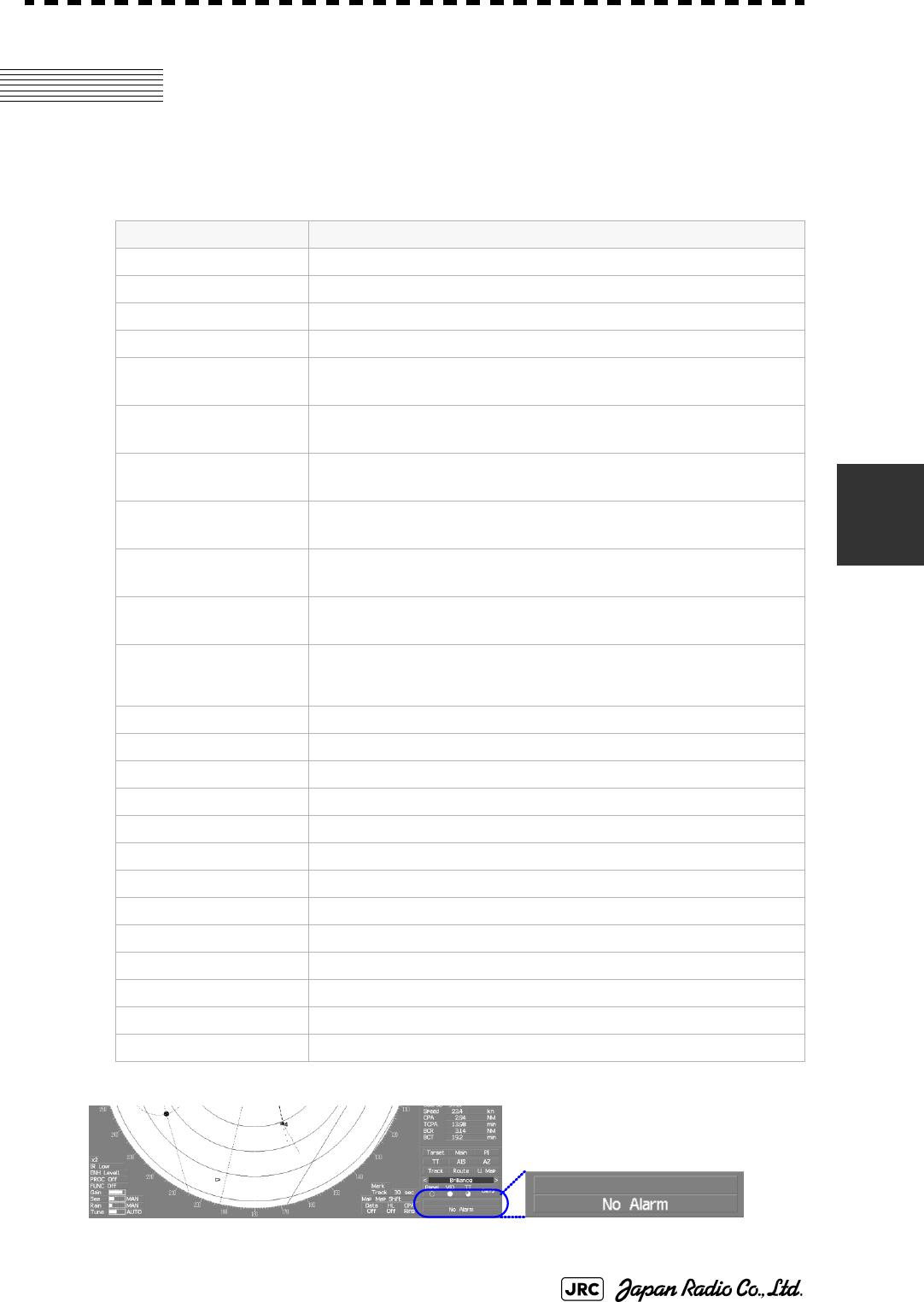
5.5 ALARM DISPLAY
Alarm messages for Target Tracking (TT) and AIS functions:
Error message and alarm are displayed in the lower right of the display.
Error message Description
CPA/TCPA There is a dangerous target.
New Target A new target is acquired in the automatic acquisition zone.
Lost There is a lost target.
REF Target The accuracy of the reference target may be decreased.
95% Capacity The number of targets being tracked by the Target Tracking
function has reached 95% of the maximum.
MAX Target The number of targets being tracked by the Target Tracking
function has reached the maximum.
AIS 95% Capacity The number of displayed AIS target symbols has reached 95%
of the maximum.
AIS MAX Target The number of received data items exceeds the maximum
number of AIS target symbols that can be displayed.
AIS ACT 95% Capacity The number of activated AIS targets by the AIS function has
reached 95% of the maximum.
AIS ACT MAX The number of activated AIS targets by the AIS function has
reached the maximum.
AIS Alarm *** Alarm information issued with the ALR sentence by the AIS.
*** is a 3-digit number which is Local Alarm No in the ALR
sentence.
AIS Alarm 001 Tx malfunction
AIS Alarm 002 Antenna VSWR exceeds limit
AIS Alarm 003 Rx channel 1 malfunction
AIS Alarm 004 Rx channel 2 malfunction
AIS Alarm 005 Rx channel 70 malfunction
AIS Alarm 006 general failure
AIS Alarm 008 MKD connection lost
AIS Alarm 025 external EPFS lost
AIS Alarm 026 no sensor position in use
AIS Alarm 029 no valid SOG information
AIS Alarm 030 no valid COG information
AIS Alarm 032 Heading lost/invalid
AIS Alarm 035 no valid ROT information
5-40
JMA-9100 Instruction Manual > 5.OPERATION OF TARGET TRACKING AND AIS > 5.5 ALARM DISPLAY
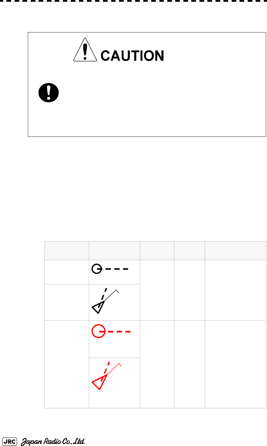
5.5.1 CPA / TCPA Alarm
In the system, targets are categorized into two types: tracked / activate AIS targets
and dangerous targets.
The grade of danger can easily be recognized on the display at a glance. So the
officer can easily decide which target he should pay attention to.
It is not possible to switch off the tracked target visual alarm, unless tracking is
ceased, or the alarm condition no longer applies.
The types of target and alarm are shown below.
CPA Limit and TCPA Limit: The Setting Values
Since these alarms may include some errors
depending on the target tracking conditions, the
navigation officer himself should make the final
decision for ship operations such as collision
avoidance.
Making the final navigation decision based only on the
alarm may cause accidents such as collisions.
CPA / TCPA Alarm
Status Symbol on
display
Alarm
characters
Alarm
sound
Conditions
Tracked target (Off) (Off) ・CPA>CPA LIMIT
・0>TCPA
・TCPA>TCPA LIMIT
The symbol is displayed
when one of the above
conditions is met.
Activated AIS
target
Dangerous
target
Red blinking
CPA/TCPA Beep
sound
(pee-poh)
Alarm
acknowle
dgeable
・CPA ≦CPA LIMIT
・0≦TCPA≦TCPA LIMIT
An alarm is issued when all
the conditions are met.
The AIS targets that issues
alarm refer to 5.3.9
Red blinking
12
AIS12
12
AIS12
JMA-9100 Instruction Manual > 5.OPERATION OF TARGET TRACKING AND AIS > 5.5 ALARM DISPLAY
5-41
5
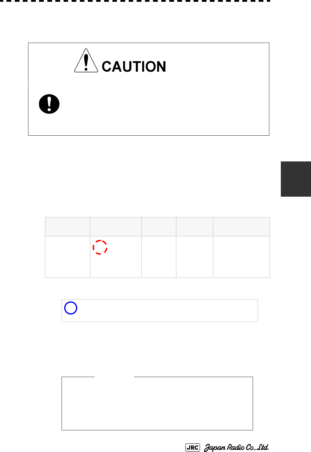
5.5.2 Alarm for New Target Acquired in Automatic Acquisition
Zone (New Target)
The automatic acquisition function sets a zone in a range and issues an alarm
when a new target (which is not yet acquired) goes into this zone.
For the setting of an automatic acquisition zone, refer to " Acquiring Target " in
Section 5.2.1.1 "Automatic acquisition".
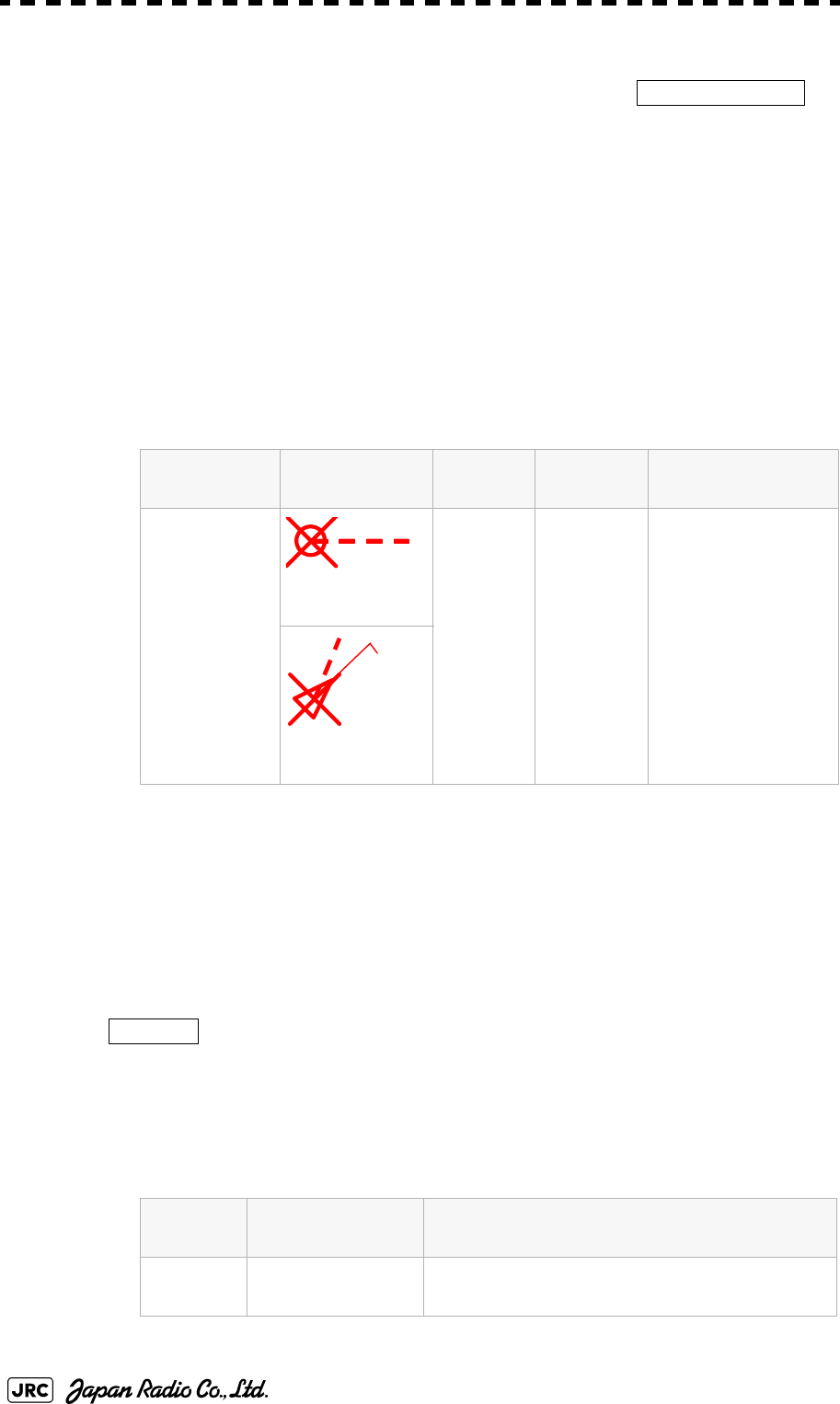
5.5.3 Lost Target Alarm (Lost)
In setting an automatic acquisition zone, it is
necessary to adjust the gain, sea clutter suppression
and rain / snow clutter suppression to ensure that
target echoes are displayed in the optimum conditions.
No automatic acquisition zone alarms will be issued
for targets undetected
Alarm for New Target Acquired in Automatic Acquisition Zone
Status Symbol on
display
Alarm
characters
Alarm sound Conditions
New target in
automatic
acquisition
zone Red Blinking
New Target Beep sound
(pipi-pipi)
Alarm
acknowledge
able
The alarm is issued
when a new target is
acquired in the
automatic acquisition
zone.
i
When an already acquired target goes into automatic
acquisition zone, the alarm message is not displayed and the
buzzer does not sound either.
• If the gain, sea clutter suppression, rain/snow clutter
suppression are not adjusted adequately, the lost
target alarm may be easily generated. So such
adjustments should be mad carefully.
12
Attention
5-42
JMA-9100 Instruction Manual > 5.OPERATION OF TARGET TRACKING AND AIS > 5.5 ALARM DISPLAY
When it is impossible to continue tracking any acquired and tracked target, or the
data of AIS target cannot received for a specified time, the
will be generated. The typical causes for alarm generation are shown below, but
not limited to the following:
•The target echo is very weak.
•The target is shadowed by a shore or a large ship and its echo is not received.
•The target echo is blurred by sea clutter returns.
If a target under tracking goes out of a range of 32 nm and can no longer be
tracked, it is canceled without a lost target alarm.
5.5.4 Gyro Set Alarm
The GYRO I/F in this system receives signals from a gyro. Even if the power is
turned off, the system will follow up the gyro. However, the system stops the
follow-up operation when the power of the master gyro is turned off or when any
trouble occurs to the line. When the power of the master gyro is recovered, the
alarm will be generated.
If this alarm occurs, set the gyro.
Lost Target Alarm
Status Symbol on
display
Alarm
characters
Alarm
sound
Conditions
Lost Target
Red Blinking
Lost Beep sound
(pee)
Alarm
acknowledge
able
The alarm will sound
once when a lost
target symbol is
displayed.
Red Blinking
Gyro Set Alarm
Alarm
characters
Alarm sound Conditions
Set Gyro Beep sound (pipi-pipi) The signals from the gyro are stopped, but the
gyro is recovered.
Lost Alarm
12
AIS12
Set Gyro
JMA-9100 Instruction Manual > 5.OPERATION OF TARGET TRACKING AND AIS > 5.6 TRACK FUNCTION
5-43
5
5.6 TRACK FUNCTION
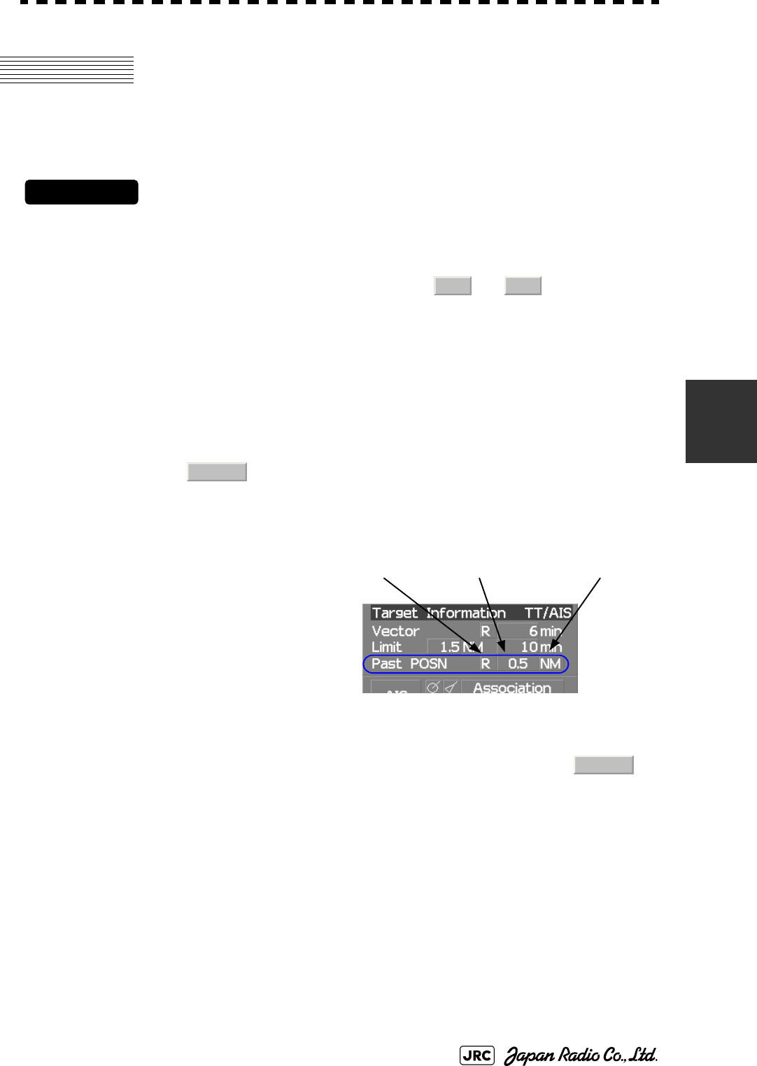
5.6.1 Past Position (Past POSN)
Procedures
1) Left-click the past position display interval unit switching button
in the Target Information located at the upper right of the display,
and set a desired unit.
The past position display interval unit will be set to or .
2) Left-click the past position display interval switching button in
the Target Information located at the upper right of the display,
and set a desired track display interval.
The past position will be set.
The past position function
can display up to ten past
positions of a target under
tracking. The past position
display interval can be set to
specified time intervals of
0.5, 1, 2, or 4 minutes, or
specified range intervals of
0.1, 0.2, 0.5, or 1 nm.
The specified interval is displayed in the past position display interval switching
in Target Information located at the upper right of the display. When is
displayed, the track display function is turned off.
The track mode operates in conjunction with the vector mode, and a true or
relative track is displayed. In relative vector mode, the relative tracks of the target
are displayed. In true vector mode, true tracks that are calculated from the relative
bearing, range, own ship's course, and speed are displayed.
The target is acquisition, past position of traced target is start plot. The AIS target
is displayed, past position of AIS target is start plot.
If the past position plotted time is short, the indicated past position duration may
not have achieved the specified time or range.
: Tracks are not displayed.
Numeric : Tracks are displayed at intervals of a specified value.
min NM
Off
Past position
display interval
Past position
true / relative
Past position
display interval unit
Off
5-44
JMA-9100 Instruction Manual > 5.OPERATION OF TARGET TRACKING AND AIS > 5.6 TRACK FUNCTION
5.6.2 Target Ship's Tracks (Target Track)
This function makes settings for the tracks of tracked targets and AIS targets.
The system can display the tracks of up to 20 target ships.
5.6.2.1 Track Color Setting (Target Track Color)
Procedures
1) Put the cursor on the tracked target or activated AIS target, and
right-click.
The setting items for cursor modes will be displayed.
2) Left-click .
The Property will appear.
3) Left-click the item button of .
The setting items for Track Color will be displayed.
4) Left-click the button corresponding to the track color to be set.
Colors set by performing the procedure in Section 5.6.2.3 "Setting of Target Ship's Track
Colors (Target Track Color)" can be selected.
Individual colors can be set for up to 10 ships. The same color is set for 11 to 20 ships.
5.6.2.2 Target Ship's Track Function On/Off (Target Track Function)
Procedures
1) Open the T.TRK menu by performing the following menu
operation.
→
2) Left-click the item button of .
The Target Track Function will be set to on or off.
: Target Track Function is turned on.
: Target Track Function is turned off.
i
Note that when this function is turned off, all the other ship's
track functions are turned off. In this case, the track data of
other ships is not saved, so they cannot be traced later.
Property
2. Track Color
TT
2. Target Track Setting
1. Target Track Function
On
Off
JMA-9100 Instruction Manual > 5.OPERATION OF TARGET TRACKING AND AIS > 5.6 TRACK FUNCTION
5-45
5
5.6.2.3 Setting of Target Ship's Track Colors (Target Track Color)
You can set either one track color for all targets under tracking, or individual
colors for the ships of track numbers 1 to 10. The tracks of ships 11 to 20 are
displayed in the same color.
Procedures
1) Open the Target Track Color menu by performing the following
menu operation.
→
→
→
The setting items for All will be displayed.
2) Left-click the button corresponding to the track display to be set.
Individual setting
3) Left-click the button corresponding to the track number to be set.
The setting items for the selected track number will be displayed.
4) Left-click the button corresponding to the track color to be set.
The track color of the selected track number will be set.
When is selected, the track numbers to and
the individual setting for are valid. Select a color for each target.
The color list is displayed by left-clicking the button corresponding to the item
number to be set. Select a desired color. There are 8 color choices: ,
, , , , , , and .
i
If the other ship's track function (Target Track Function) is
turned off, the track data of other ships is not saved.
: Track color is set individually for ships.
color name : One color is set for all ships.
~ : Setting for 1 to 10 ships
: Setting for 11 to 20 ships
i
Note that the individual setting is not enabled unless Individual
is selected.
TT
2. Target Track Setting
2. Target Track Color
1. All
Individual
Individual
Target Track No.1
No.10
Other
Off
White Gray Blue Green Yellow Pink Red
Target Track No.1
No.10
Other
5-46
JMA-9100 Instruction Manual > 5.OPERATION OF TARGET TRACKING AND AIS > 5.6 TRACK FUNCTION
5.6.2.4 Setting of Target Ship's Track Display (Target Track Display)
The target track display function can be turned on / off. Choices for track display
are displaying / hiding the tracks of all ships and Individual (displaying the tracks
of individual ships).
Procedures
1) Open the Target Track Display menu by performing the following
menu operation.
→
→
→
The setting items for All will be displayed.
2) Left-click the button corresponding to the track display to be set.
Individual setting
3) Left-click the button corresponding to the track number to be set.
The selected track number display will be set to on or off.
When is selected, the track numbers to and
the individual setting for are valid. Select on / off for each target.
: Track display is set for individual ships.
: The tracks of all ships are hidden.
: The tracks of all ships are displayed.
i
Even when Target Track Display is turned off, the track data of
other ships is saved if Track Memory Interval is set.
:The track number display is turned on.
:The track number display is turned off.
~ : Setting for 1 to 10 ships
: Setting for 11 to 20 ships
i
Note that the individual setting is not enabled unless Individual
is selected.
TT
2. Target Track Setting
3. Target Track Display
1. All
Individual
Off
On
On
Off
Individual
Target Track No.1 No.10
Other
Target Track No.1 No.10
Other
JMA-9100 Instruction Manual > 5.OPERATION OF TARGET TRACKING AND AIS > 5.6 TRACK FUNCTION
5-47
5
5.6.2.5 Setting of Target Ship's Track Saving Interval (Track Memory Interval)
An interval for saving target ship's track data can be set.
Procedures
1) Open the Track Memory Interval menu by performing the
following menu operation.
→
→
2) Left-click the button corresponding to the interval to be set.
Select an interval from the following:
5.6.2.6 Clear of Target Ship's Track (Clear Track)
The target ship's track can be cleared by setting a color or a track number.
[1] Clear of Tracks by Setting Color (Clear Track Color)
Procedures
1) Open the Clear Track Color menu by performing the following
menu operation.
→
→
The setting items for Clear Track Color will be displayed.
i
This function is not available when the Target Track Function is
turned off.
Off/
3sec/5sec/10sec/30sec/
1min/3min/5min/10min/30min/60min/
1NM/3NM/5NM/10NM
i
If Card T.TRK Display is used, target ship's tracks displayed
through the card cannot be cleared.
TT
2. Target Track Setting
4. Track Memory Interval
TT
2. Target Track Setting
5. Clear Track Color

5-48
JMA-9100 Instruction Manual > 5.OPERATION OF TARGET TRACKING AND AIS > 5.6 TRACK FUNCTION
2) Left-click the button corresponding to the color of the target
tracks to be cleared.
The Confirmation Window will appear.
3) Left-click to clear the track line.
All the tracks of the selected color will be cleared.
[2] Clear of Tracks by Setting Track Number (Clear Track Number)
Procedures
1) Open the T.TRK menu by performing the following menu
operation.
→
→
The setting items for Clear Track Number will be displayed.
2) Left-click the button corresponding to the number of the tracks
to be cleared.
The Confirmation Window will appear.
3) Left-click to clear the track line.
The tracks of the selected number will be cleared.
5.6.2.7 Operation of Target Ship's Track Data Saved on Card (File
Operations)
Target ship's track data can be saved on a flash memory card and read from the
card.
[1] Loading File (Load)
Procedures
1) Insert a flash memory card into the card slot
Flash memory card (option) is necessary.
i
Data can be saved to a flash memory card until the card
becomes full, but the number of files that can be read and
displayed is limited to 64 in alphanumeric order. When the
number of files has reached 64, delete unnecessary files.
1. Yes
TT
2. Target Track Setting
6. Clear Track Number
1. Yes

JMA-9100 Instruction Manual > 5.OPERATION OF TARGET TRACKING AND AIS > 5.6 TRACK FUNCTION
5-49
5
2) Open the File Operations menu by performing the following
menu operation.
→
→
3) Left-click the item button of to select a card slot.
The setting item for Select Card Slot is switched between Slot1 and Slot2.
4) Left-click the item button of to select Add or
Overwrite.
The setting item for Load Mode is switched between and
.
When is selected, new data is added to the current data on the
card. When is selected, new data is saved over the current data
on the card.
5) Left-click .
Currently saved target ship's track data will be listed.
6) Left-click the button corresponding to the file to be loaded.
The Confirmation Window will appear.
7) Left-click to load the file.
The selected target track data will be loaded and shown on the radar display.
[2] Saving File (Save)
Procedures
1) Insert a flash memory card into the card slot.
Flash memory card (option) is necessary.
TT
2. Target Track Setting
7. File Operations
1. Select Card Slot
2. Load Mode
Add
Overwrite
Add
Overwrite
3. Load
1. Yes

5-50
JMA-9100 Instruction Manual > 5.OPERATION OF TARGET TRACKING AND AIS > 5.6 TRACK FUNCTION
2) Open the File Operations menu by performing the following
menu operation.
→
→
3) Left-click the item button of to select a card
slot.
The setting item for Select Card Slot is switched between Slot1 and Slot2.
4) Left-click .
The Input File Name menu will appear.
5) Input the file name to be saved.
Up to ten characters can be input as a file name.
For inputs to the characters input screen, refer to Section 3.3.4.7 "Entering a character". After
the input, the Confirmation Window will appear.
6) Left-click to save the file.
The currently displayed target track data will be saved.
TT
2. Target Track Setting
7. File Operations
1. Select Card Slot
4. Save
1. Yes

JMA-9100 Instruction Manual > 5.OPERATION OF TARGET TRACKING AND AIS > 5.6 TRACK FUNCTION
5-51
5
[3] Erasing File (Erase)
Procedures
1) Insert the flash memory card into the card slot.
Flash memory card (option) is necessary.
2) Open the File Operations menu by performing the following
menu operation.
→
→
3) Left-click the item button of to select a card
slot.
The setting item for Select Card Slot is switched between Slot1 and Slot2.
4) Left-click .
The Erase menu will appear.
Currently saved target ship's track data on the card will be listed.
5) Left-click the button corresponding to the file to be erased.
The Confirmation Window will appear.
6) Left-click to erase the file.
The selected target track data will be erased and the file name will disappear from the list.
TT
2. Target Track Setting
7. File Operations
1. Select Card Slot
5. Erase
1. Yes

5-52
JMA-9100 Instruction Manual > 5.OPERATION OF TARGET TRACKING AND AIS > 5.6 TRACK FUNCTION
[4] Displaying File (Card Target Track Display)
Procedures
1) Insert the flash memory card into the card slot.
Flash memory card (option) is necessary.
2) Open the File Operations menu by performing the following
menu operation.
→
→
3) Left-click the item button of to select a card
slot.
The setting item for Select Card Slot is switched between Slot1 and Slot2.
4) Left-click .
The Card T.TRK Display menu will appear.
Currently saved target ship's track data on the card will be listed.
5) Left-click the button corresponding to the file to be displayed.
The Confirmation Window will appear.
6) Left-click to display the T.TRK line.
The selected file will be highlighted, and the currently saved target track data will be
displayed.
Cancel
1) Open the Card T.TRK Display window.
The displayed file is highlighted.
2) Left-click the button corresponding to the displayed file.
The file will be deselected and returned to normal display.
TT
2. Target Track Setting
7. File Operations
1. Select Card Slot
6. Card T.TRK Display
1. Yes

JMA-9100 Instruction Manual > 5.OPERATION OF TARGET TRACKING AND AIS > 5.7 TRIAL MANEUVERING (Trial Maneuver)
5-53
5
5.7 TRIAL MANEUVERING
(Trial Maneuver)
The trial maneuvering is the function of simulating own ship’s course and speed
for collision avoidance when a dangerous target appears. When the own ship's
course and speed are entered in manual mode, the trial maneuvering function
checks if pre-acquired or pre-activated targets are dangerous.
The ranges of course and speed to be entered manually:
• Trial maneuvering is to simulate own ship’s course
and speed in the conditions that the course and
speed of a target ship are unchanged as they are.
As the situation is different from any actual ship
maneuvering, set values with large margins to CPA
Limit and TCPA Limit.
Course: 360° (in 0.1° intervals) ............................................... [EBL] dial
Speed: 0 to 100kn (in 0.1kn step)........................................ [VRM] dial
Attention
5-54
JMA-9100 Instruction Manual > 5.OPERATION OF TARGET TRACKING AND AIS > 5.7 TRIAL MANEUVERING (Trial Maneuver)
5.7.1 Trial Maneuvering in the True Vector Mode
In the True Vector mode, calculations are performed according to the values set
by Trial Speed, Trial Course and other features, and the result is displayed as a
bold-line that represents the change of own ship's vector as shown in the Fig 5-7
below (an example of the course changed to the right).
In this Fig 5-7, the dangerous target forward left becomes safe as a result of
simulation.
The tracked target information indicates the current CPA and TCPA values
regardless of the result of simulation.
Fig 5-7: True Vector Mode
Dangerous target
HL
Change of symbol
as a result of
trial maneuver
HL
T
TRIAL
NORMAL
Route
Own ship’s vector

JMA-9100 Instruction Manual > 5.OPERATION OF TARGET TRACKING AND AIS > 5.7 TRIAL MANEUVERING (Trial Maneuver)
5-55
5
5.7.2 Trial Maneuvering in the Relative Vector Mode
The result of Trial maneuvering in the Relative Vector mode is shown by a
change in target vector. In the Fig 5-8 below (in the same conditions as in the True
Vector mode in the previous page), it is seen that the acquired target is a
dangerous one because its vector is crossing the CPA RING.
Fig 5-8: Relative Vector Mode
The above Fig 5-8 shows that the relative vector of the target has changed as
shown in the figure as a result of simulation (course and speed), so that the
symbol color is changed into “White”, a safe target.
Irrespective of the simulation results, the current CPA and TCPA values are shown
in the tracked target information just like when the true vector mode is active.
The course change of own ship is displayed as a dotted-line.
Better information is provided by using relative motion and sea stabilization.
CPA Ring
Change of symbol
as a result of
trial maneuver
TRIAL
NORMAL
Dangerous target
CPA Ring
HL
HL
T
5-56
JMA-9100 Instruction Manual > 5.OPERATION OF TARGET TRACKING AND AIS > 5.7 TRIAL MANEUVERING (Trial Maneuver)
5.7.3 Operation of Trial Maneuvering Function
Procedures
1) Open the Trial Maneuver menu by performing the following menu
operation.
→
2) Left-click the item button of .
The Trial Function will be set to on or off.
When Trial Function is set to on, the character " T " indicating trial maneuvering blinks in
the own ship display field of the radar display.
3) Set values for Course by turning the [EBL] dial, and for Speed by
turning the [VRM] dial.
4) Set other characteristics.
For inputs to the value input screen, refer to Section 3.3.4.2 "Directly entering a numeric
value".
Dangerous target symbols are displayed in red and safe target symbols in white.
: The trial maneuvering function is turned on.
: The trial maneuvering function is turned off.
: Vector time (1 to 60 min)
: Time until trial maneuvering is started (0 to 30 min)
: Dynamic trait of the own ship
→ : Range from when steered to when the ship
beings to turn (0 to 2000 m)
→ : Turning radius (0.10 to 2.00 nm)
→ : Acceleration (0.0 to 100 knots/min)
→ : Deceleration (0.0 to 100 knots/min)
i
Vector Time is valid only when Trial Function is set to on. If it is off, the vector time
before trial maneuvering is displayed.
Time until the start of trial maneuvering is counted down immediately after the input.
The acceleration and deceleration are influenced depending on the relationship
between the current speed and the input speed for trial maneuvering.
If 0.0 kn/min is set for Acceleration when the speed for trial maneuvering is faster
than the current speed, or for Deceleration when the speed for trial maneuvering is
slower than the current speed, the system performs simulation on the assumption
that the speed is changed immediately after the time set for Time to Maneuver .
TT
3. Trial Maneuver
1. Trial Function
On
Off
Vector Time
Time to Maneuver
Own Ship Dynamic Trait
Reach
Turn Radius
Acceleration
Decceleration

JMA-9100 Instruction Manual > 5.OPERATION OF TARGET TRACKING AND AIS > 5.7 TRIAL MANEUVERING (Trial Maneuver)
5-57
5
Cancel
1) Open the Trial Maneuver menu by performing the following
menu operation.
→
2) Left-click the item button of .
The Trial Function will be set to on or off.
:The Trial Function will be set to off.
TT
3. Trial Maneuver
1. Trial Function
Off

5-58
JMA-9100 Instruction Manual > 5.OPERATION OF TARGET TRACKING AND AIS > 5.7 TRIAL MANEUVERING (Trial Maneuver)

TRUE AND FALSE ECHOES ON DISPLAY
6.1 RADAR WAVE WITH THE HORIZON ...................................................6-1
6.2 STRENGTH OF REFLECTION FROM THE TARGET ...........................6-3
6.3 SEA CLUTTER AND RAIN AND SNOW CLUTTER ..............................6-5
6.4 FALSE ECHOES ....................................................................................6-9
6.5 DISPLAY OF RADAR TRANSPONDER (SART) ................................6-12
SECTION 6
TRUE AND FALSE ECHOES ON DISPLAY
JMA-9100 Instruction Manual > 6.TRUE AND FALSE ECHOES ON DISPLAY > 6.1 RADAR WAVE WITH THE HORIZON
6-1
6
The radar operator has a role of interpreting the radar displays to provide his best
aid in maneuvering the ship. For this purpose, the operator has to observe the
radar displays after fully understanding the advantages and disadvantages that the
radar has. For better interpretation of radar display, it is important to gain more
experiences by operating the radar equipment in fair weathers and comparing the
target ships watched with the naked eyes and their echoes on the radar display.
The radar is mainly used to monitor the courses of own ship and other ships in
open seas, to check buoys and other nautical marks when entering a port, to
measure own ship’s position in the coastal waters relative to the bearings and
ranges of the shore or islands using a chart, and to monitor the position and
movement of a heavy rain if it appears on the radar display.
Various types of radar display will be explained below.
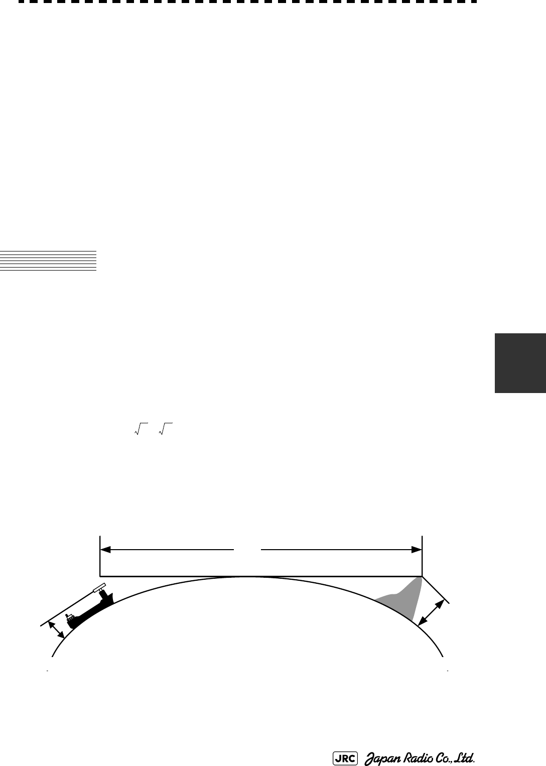
6.1 RADAR WAVE WITH THE HORIZON
Radar beam radiation has the nature of propagating nearly along the curved
surface of the earth. The propagation varies with the property of the air layer
through which the radar beam propagates. In the normal propagation, the distance
(D) of the radar wave to the horizon is approximately 10% longer than the
distance to the optical horizon. The distance (D) is given by the following
formula:
[NM]
: Height (m) of radar scanner above sea level
: Height (m) of a target above sea level
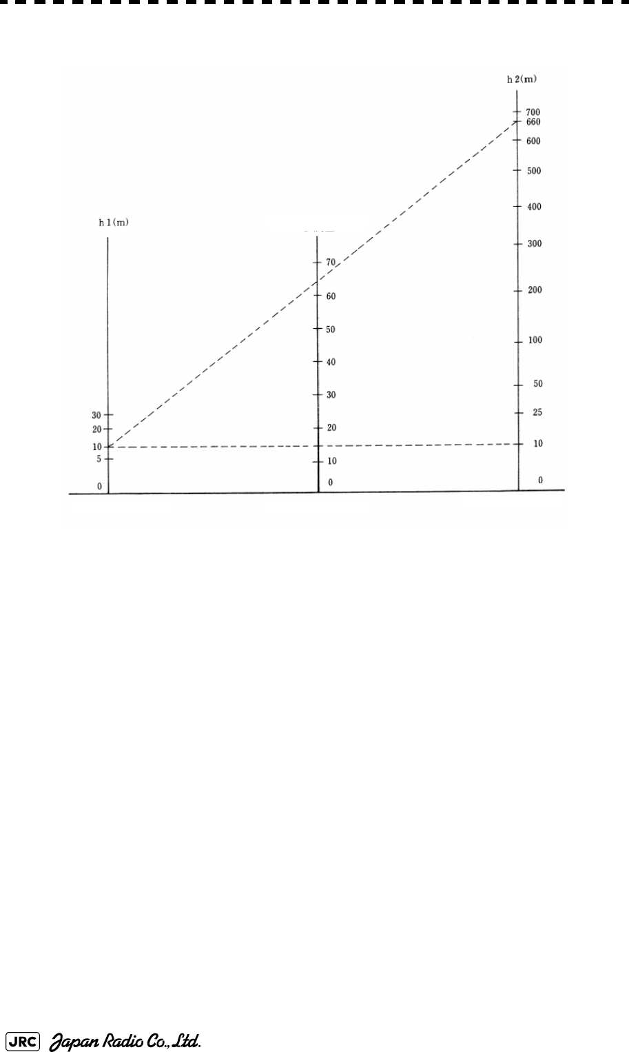
Fig 6-2 is a diagram for determining the maximum detection range of a target that
is limited by the curve of the earth surface in the normal propagation.
Fig 6-1: RADAR wave with the horizon
D
2.23
h
1
h
2
+()=
h
1
h
2
D
Earth
h
1
h
2
Radar Targets
6-2
JMA-9100 Instruction Manual > 6.TRUE AND FALSE ECHOES ON DISPLAY > 6.1 RADAR WAVE WITH THE HORIZON
Fig 6-2: Maximum detection range of a target
When the height of own ship’s scanner is 10 m for instance,
i. A target that can be detected at the radar range of 64 nm on the radar display
is required to have a height of 660 m or more.
ii. If the height of a target is 10 m, the radar range has to be approx. 15 nm.
However, the maximum radar range at which a target can be detected on the
radar display depends upon the size of the target and the weather conditions,
that is, the radar range may increase or decrease depending upon those
conditions.
Height of RADAR Scanner Detective Range Height of Target
D[NM]
JMA-9100 Instruction Manual > 6.TRUE AND FALSE ECHOES ON DISPLAY > 6.2 STRENGTH OF REFLECTION FROM THE
TARGET
6-3
6
6.2 STRENGTH OF REFLECTION FROM
THE TARGET
The signal intensity reflected from a target depends not only on the height and size
of the target but also on its material and shape. The echo intensity from a higher
and larger target is not always higher in general.
In particular, the echo from a coast line is affected by the geographic conditions of
the coast. If the coast has a very gentle slop, the echo from a mountain of the
inland appears on the radar display.(Fig 6-3) Therefore, the distance to the coast
line should be measured carefully.
Fig 6-3: Sea shore line which is not displayed
Table 6-1 shows the graph indicating the relation between the target detection
distance and the radar reflection cross-sectional area (RCS) with regard to the type
and the height of the target in a situation in which the weather is good, the sea
state is calm and the radio wave propagation is normal. As revealed by this table,
even on the same sea shore line, detection distance greatly differs depending on
the height of the target from the surface of the sea. Furthermore, because the
target detection distance is greatly influenced by the shape and material of the
target and environmental conditions, such as the sea state, weather, and radio
wave propagation, caution should be taken when detecting distance of target.
Mountain displayed
on the radar display
Sea shore line not displayed
HL
6-4
JMA-9100 Instruction Manual > 6.TRUE AND FALSE ECHOES ON DISPLAY > 6.2 STRENGTH OF REFLECTION FROM THE
TARGET
Table 6-1: Relation between type and height of target and detection distance and RCS
Type of target Height from
sea surface
(m)
Detection distance
(NM)
RCS
X band S band X band S band
Sea shore line 60 20 20 50,000 50,000
Sea shore line 6 8 8 5000 5000
Sea shore line 3 6 6 2500 2500
SOLAS target ship (>5000GT) 10 11 11 50,000 30,000
SOLAS target ship (>500GT) 5 8 8 1800 1000
Small boat with IMO standard
compatible radar reflector
45.03.77,50,5
Marine buoy with corner
reflector
3,5 4.9 3.6 10 1
Standard marine buoy 3,5 4.6 3.0 5 0,5
10-meter small boat without
radar reflector
23.43.02,51,4
Waterway location beacon 1 2.0 1.0 1 0,1
Detection distance shown in the above table may greatly
decrease depending on the shape of the target, sea state,
weather and radio wave propagation conditions.
m
2
[]
i
JMA-9100 Instruction Manual > 6.TRUE AND FALSE ECHOES ON DISPLAY > 6.3 SEA CLUTTER AND RAIN AND SNOW
CLUTTER
6-5
6
6.3 SEA CLUTTER AND RAIN AND SNOW
CLUTTER
In addition to the echo required for observing ships and land, radar video image
also includes unnecessary echo, such as reflection from waves on the sea surface
and reflection from rain and snow. Reflection from the sea surface is called "sea
clutter," and reflection from rain and snow is called "rain and snow clutter," and
those spurious waves must be eliminated by the clutter rejection function.
a. Sea clutter
Sea clutter appears as an image radiating outwardly from the center of the radar
display and changing depending on the size and the shape of waves. Generally, as
waves become larger, image level of the sea clutter is intensified and the clutter
far away is also displayed. When waves are large and the sea clutter level is high,
it is difficult to distinguish sea clutter from a small boat whose reflection intensity
is weak. Accordingly, it is necessary to properly adjust the sea clutter rejection
function. Table 6-2 shows the relation between the sea state (SS) showing the size
of waves generated by wind and the radar's detection probability.
Table 6-2: Sea state and probability of target detection
S band radar (probability to detect a target at a distance of 0.4 NM)
RCS SS1~2SS2~3SS3~4SS4~5
0.1m2 Vi
i. V: Detection probability of 80 %
V-Mii
ii. M: Detection probability of 50 %
M-NViii
iii. NV: Detection probability of less than 50 %
0.5 m2 V V V-M M-NV
1 m2VVVV-M
X band radar (probability to detect a target at a distance of 0.7 NM)
RCS SS1~2SS2~3SS3~4SS4~5
1m2 V-M M-NV
5 m2 V V-M M-NV
10 m2VVVV-M
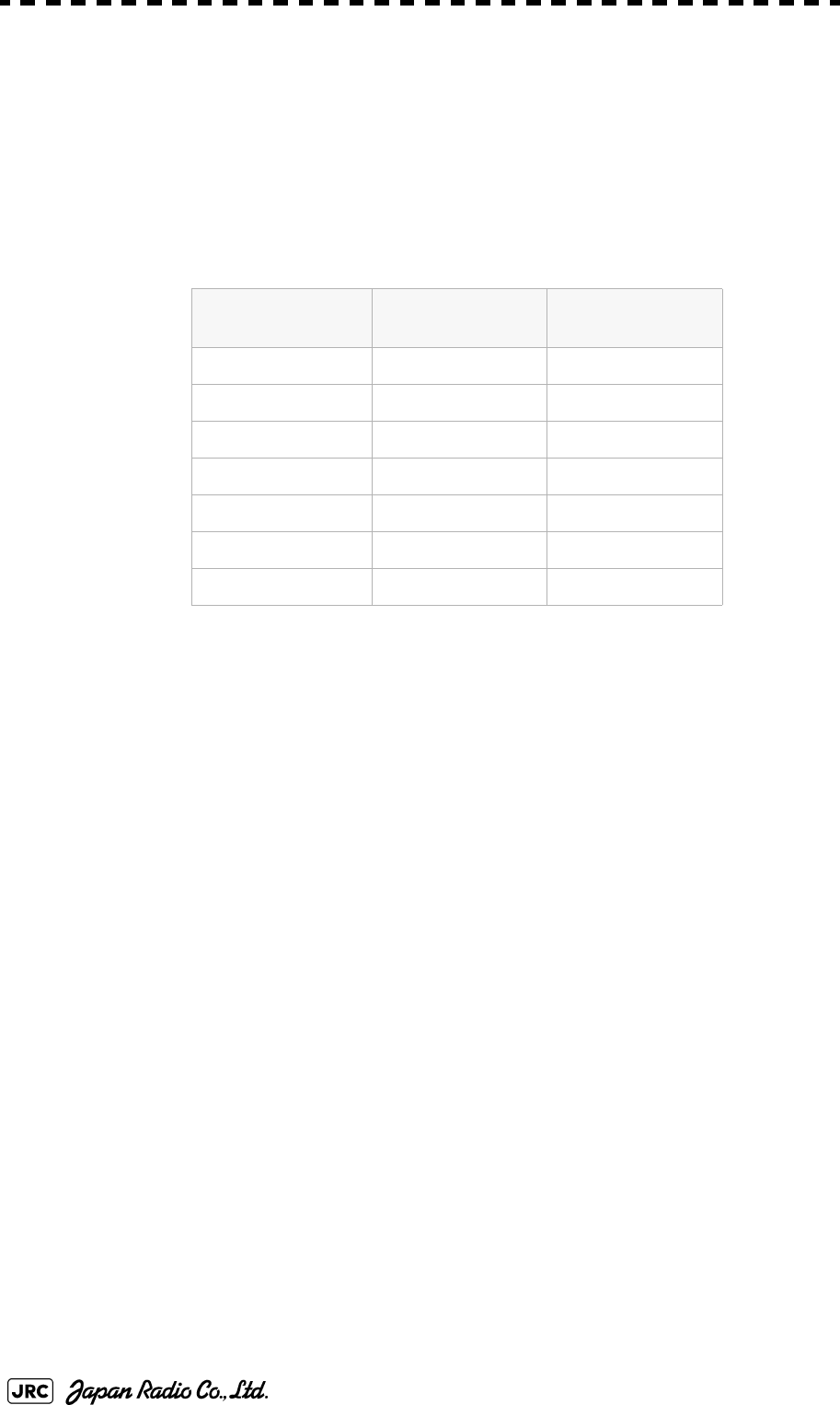
6-6
JMA-9100 Instruction Manual > 6.TRUE AND FALSE ECHOES ON DISPLAY > 6.3 SEA CLUTTER AND RAIN AND SNOW
CLUTTER
As shown in Table 6-2, the number of SS increases as the wind speed becomes
high and the waves become large. Table 6.2 reveals that detection probability
decreases from V (80 %) to NV (less than 50 %) as the number of SS increases.
Therefore, even if the sea state is calm and a target clearly appears on the radar
display, when the sea state becomes rough, target detection probability decreases
resulting in difficulty of target detection by the radar.
For example, in the case of a standard marine buoy, RCS of X band radar is 5 m2
as shown in Table 6-1. When observing such a target in the sea state (SS3) in
which significant wave height exceeds 1.2 meters, detection probability is M-NV,
as shown in Table 6-2, which indicates 50 % or less.
b. Rain and snow clutter
Rain and snow clutter is a video image that appears in a location where rain or
snow is falling. The image changes according to the amount of rain (or the
amount of snowfall). As precipitation increases, the image of rain and snow
clutter becomes intensified on the radar display, and in the case of localized heavy
rain, an image similar to the image indicating land is displayed in some cases.
Furthermore, because radio waves tend to attenuate due to rain and snow, the
ability to detect a target in the rain and snow clutter or a target beyond the rain and
snow clutter may decrease. The amount of attenuation depends on the
transmission frequency, antenna beam width, and the pulse length. Fig 6-4 and
Fig 6-5 show examples in which detection distance is reduced due to the influence
of precipitation. Because of this, a target, which clearly appeared up to 10 NM by
an X band radar (pulse width of 0.8μs) when it was not raining, may become
dimly visible up to 5 NM when the amount of rain becomes 4 millimeters per
hour. Furthermore, when comparing the X band radar with the S band radar,
target detection distance decreases less when an S band radar is used, which
means it is influenced less by precipitation.
Table 6-3: Relation between Douglas sea state and average wind speed and significant
wave height
Sea state Average wind
speed (kn)
Significant wave
height (m)i
i. Significant wave height: an average of top N/3 higher waves when
the number of waves detected within a constant time duration is N
0<4<0,2
15-70,6
27-110,9
3 12-16 1,2
4 17-19 2,0
5 20-25 3,0
6 26-33 4,0
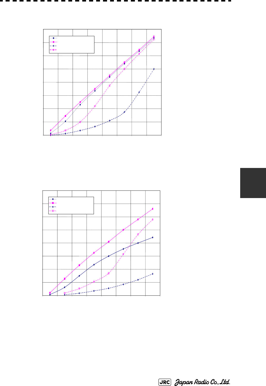
JMA-9100 Instruction Manual > 6.TRUE AND FALSE ECHOES ON DISPLAY > 6.3 SEA CLUTTER AND RAIN AND SNOW
CLUTTER
6-7
6
0
2
4
6
8
10
12
14
16
0
2
4
6
81012 14 16
降
雨
時
の
検
出
距
離
(NM)
雨の降っていないときの検出距離(NM)
16mm/hr の降雨時 パルス幅 0.05us
4mm/hr の降雨時 パルス幅 0.05us
16mm/hr の降雨時 パルス幅 0.8us
4mm/hr の降雨時 パルス幅 0.8us
Detection distance while it is not rainning[NM]
Detection distance while it is raining [NM]
Pre cip it at io n of 16 mm/hr Pulse width 0.8us
Pre cip it at io n of 4 mm/hr Pulse width 0.8us
Pre cip it at io n of 4 mm/hr Pulse width 0.05us
Pre cip it at io n of 16 mm/hr Pulse width 0.05us
Fig 6-4: Decreased target detection distance by S band radar due to
precipitation
0
2
4
6
8
10
12
14
16
024
6810 12 14 16
降
雨
時
の
検
出
距
離
(NM)
16mm/hr の降雨時 パルス幅 0.05us
4mm/hr の降雨時 パルス幅 0.05us
16mm/hr の降雨時 パルス幅 0.8us
4mm/hr の降雨時 パルス幅 0.8us
雨の降っていないときの検出距離(NM)
Detection distance while it is not rainning[NM]
Detection distance while it is raining [NM]
Pr e cipit a tion of 16 mm /hr Pulse width 0.8us
Pr e cipit a tion of 4 mm /hr Pulse width 0. 8us
Pr e cipit a tion of 4 mm /hr Pulse width 0. 05us
Pr e cipit a tion of 16 mm /hr Pulse width 0.05us
Fig 6-5: Decreased target detection distance by X band radar due to
precipitation

6-8
JMA-9100 Instruction Manual > 6.TRUE AND FALSE ECHOES ON DISPLAY > 6.3 SEA CLUTTER AND RAIN AND SNOW
CLUTTER
c. Coping with sea clutter and rain and snow clutter
When the weather is bad and the ocean is rough, the use of an S band radar is
effective because the radar is not influenced by sea clutter so much and
attenuation due to rain drops is small. When an X band radar is used, reducing the
pulse width will reduce the influence by spurious waves, and also the spurious
wave rejection function effectively works; therefore, the use of short pulse is
effective when the weather is bad. By using image processing functions PROCl 1
to 3, it is expected that spurious waves are further suppressed. Since optimal
settings for those items can be automatically made by using the function mode, it
is recommended that STORM or RAIN be used by selecting the function mode
when the weather is bad. For details of the function mode, see Section 3.9 "USE
FUNCTION KEY [USER]".
However, these functions may make some targets invisible, particularly targets
with higher speeds.
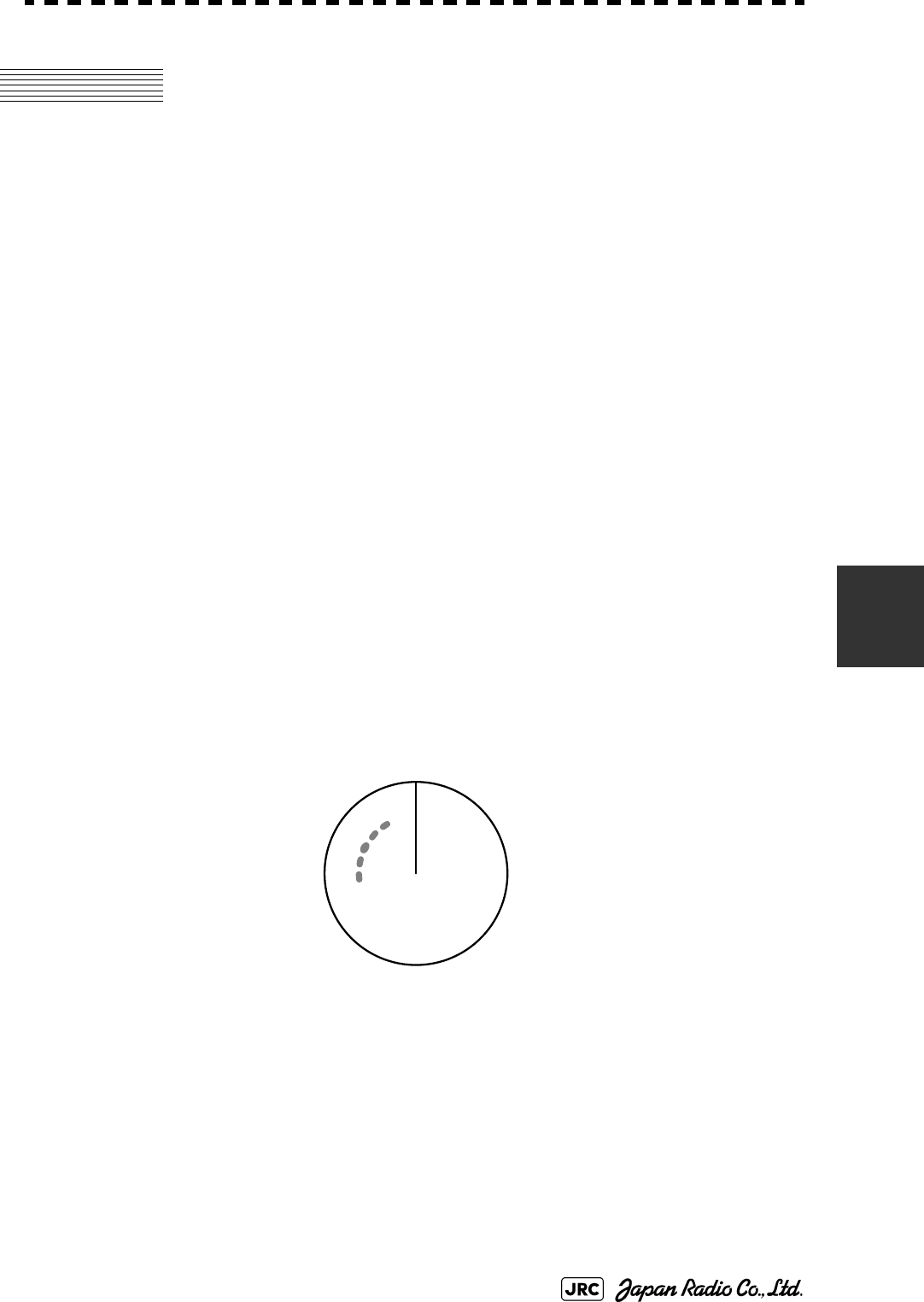
JMA-9100 Instruction Manual > 6.TRUE AND FALSE ECHOES ON DISPLAY > 6.4 FALSE ECHOES
6-9
6
6.4 FALSE ECHOES
The radar observer may be embarrassed with some echoes that do not exist
actually. These false echoes appear by the following causes that are well known:
a. Shadow
When the radar scanner is installed near a funnel or mast, the echo of a target that
exists in the direction of the funnel or mast cannot appear on the radar display
because the radar beam is reflected on the funnel or mast. Whether there are some
false echoes due to shadows can be checked monitoring the sea clutter returns, in
which there may be a part of weak or no returns.
Such shadows appear always in the same directions, which the operator should
have in mind in radar operation.
b. Side Lobe Effect
A broken-line circular arc may appear at the same range as the main lobe of the
radar beam on the radar display. This type of false echo can easily be
discriminated when a target echo appears isolated. (see Fig 6-6)
Fig 6-6: False echo
HL
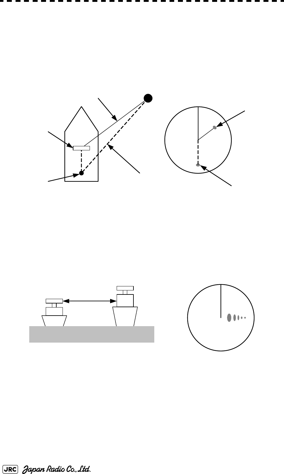
6-10
JMA-9100 Instruction Manual > 6.TRUE AND FALSE ECHOES ON DISPLAY > 6.4 FALSE ECHOES
c. False Echo by Secondary Reflection
When a target exists near own ship, two echoes from the single target may appear
on the radar display.
One of those echoes is the direct echo return from the target and the other is the
secondary reflection return from a mast or funnel that stands in the same direction
as shown in Fig 6-7.
Fig 6-7: False echo by secondary reflection
d. False Echo by Multiple Reflection
When there is a large structure or ship with a high vertical surface near own ship
as shown in Fig 6-8, multiple refection returns may appear on the radar display.
These echoes appear in the same intervals, of which the nearest echo is the true
echo of the target.
Fig 6-8: False echo by mutiple reflection
e. Second Time Echoes
The maximum radar detection range depends upon the height of the scanner and
the height of a target as described in the Section 6.1 "RADAR WAVE WITH THE
HORIZON". If a so-called “duct” occurs on the sea surface due to a certain
weather condition, however, the radar beam may propagate to a abnormally long
distance, at which a target may be detected by the radar.
Radar
scanner
Funnel
HL
Direct microwave
Secondary reflection
of microwave
Actual target
False echo from funnel
HL
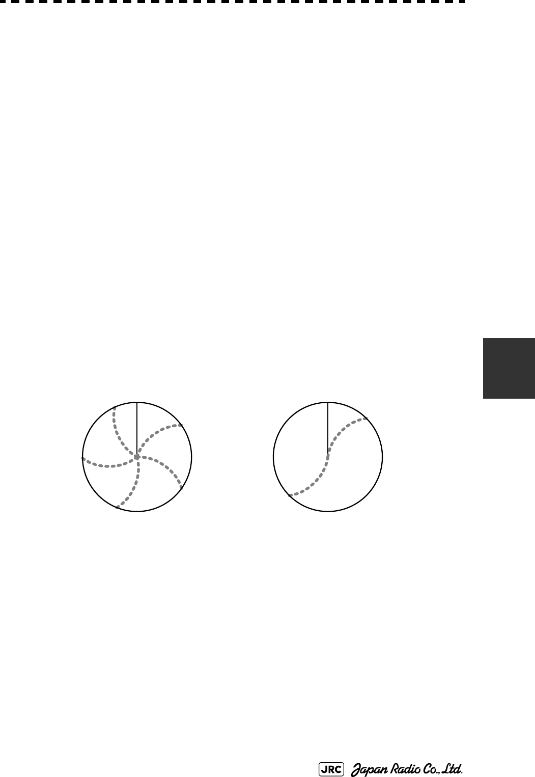
JMA-9100 Instruction Manual > 6.TRUE AND FALSE ECHOES ON DISPLAY > 6.4 FALSE ECHOES
6-11
6
For instance, assuming that the pulse length is MP3 (on the repetition frequency
of 1400 Hz), the first pulse is reflected from a target at about 58 NM or more and
received during the next pulse repetition time. In this case, a false echo (second
time echo) appears at a position that is about 58 NM shorter than the actual
distance. If the false echo appears at 5 NM on the radar display, the true distance
of the target is 5+58=63 NM. On the pulse length is SP1 (on the repetition
frequency of 2250 Hz), a false echo may appear at a position that is about 36 NM
shorter than the actual distance.
This type of false echo can be discriminated by changing over the range scale (the
repetition frequency), because the distance of the target changes accordingly.
If second time echo is appeared, the use of Economy mode in PRF menu is
effective. Otherwise, Stagger Trigger menu set to on. (See Section 3.8.3 "Set
Scanner Unit (TXRX Setting)").
f. Radar Interference
When another radar equipment using the same frequency band as that on own ship
is near own ship, a radar interference pattern may appear on the radar display.
This interference pattern consists of a number of spots which appear in various
forms. In many cases, these spots do not always appear at the same places, so that
they can be discriminated from the target echoes. (See Fig 6-9)
Fig 6-9: Radar interference
If radar equipment causing an interference pattern and this radar are of the same
model, their transmitting repetition frequency is nearly the same. As a result,
interference patterns may be displayed concentrically.
In this case, the interference patterns cannot be eliminated by using only the
interference reflector function, so ine-tune the transmitting repetition frequency.(
See Section 3.8.3 "Set Scanner Unit (TXRX Setting)")
An interference suppressing effect can be heightened by applying a different
transmitting repetition frequency to the interference pattern source radar and this
radar.
HL HL
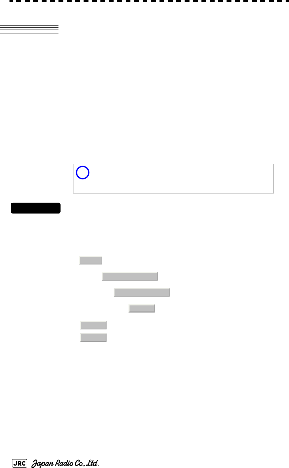
6-12
JMA-9100 Instruction Manual > 6.TRUE AND FALSE ECHOES ON DISPLAY > 6.5 DISPLAY OF RADAR TRANSPONDER (SART)
6.5 DISPLAY OF RADAR
TRANSPONDER (SART)
The SART (Search and rescue Radar Transponder) is a survival device authorized
by the GMDSS (Global Maritime Distress and Safety System), which is used for
locating survivors in case that a distress accident occurs at sea. The SART is
designed to operate in the 9 GHz frequency band.
When receiving the 9 GHz radar signal (interrogating signal) transmitted from the
radar equipment on a rescue ship or search aircraft, the SART transmit a series of
response signals to inform the distress position to the rescue and search party.
Procedures
1) Press [RANGE +] or [RANGE -] key to set the radar range to 6 NM
or 12 NM.
2) Set the SART display mode according to the procedures below.
→
→
→
With the SART display mode set to ON, settings as shown below are made automatically.
This radar provides a shortcut item to make settings for SART
signal reception. Execution of this item automatically switches
to the setting for SART reception.It also functions for detect the
beacon or target enhancer.
:SART ON
:SART OFF
Sea clutter control : Minimum (Most counterclockwise)
AUTO SEA function : OFF
Rain and Snow Clutter Control (RAIN) : Minimum
Auto Rain and Snow Clutter function
(AUTO RAIN)
:OFF
TUNE control : No tuning (to weaken clutter
echoes)
Interference rejection (IR) : OFF
PROCESS : OFF
i
Main
3. RADAR Menu
1. Process Setting
9. SART
On
Off
JMA-9100 Instruction Manual > 6.TRUE AND FALSE ECHOES ON DISPLAY > 6.5 DISPLAY OF RADAR TRANSPONDER (SART)
6-13
6
[Example of Display]
• When the SART function is set to ON, small targets around own
ship will disappear from the radar display. So it is necessary to
exercise full surveillance over the conditions around own ship by
visual watch in order to avoid any collision or stranding.
If two or more sets of radar equipment are installed on own ship,
use one set of 9 GHz band radar for detection of the SART signal
and operate others as normal radars for avoiding collision,
monitoring targets around own ship, and checking on own ship’
s position and avoidance of stranding.
After end of detecting the START signal, turn the START display
off. Then the radar returns normally to the nautical mode.
Other Ships
Land
SART code
Position of
SART
Attention

6-14
JMA-9100 Instruction Manual > 6.TRUE AND FALSE ECHOES ON DISPLAY > 6.5 DISPLAY OF RADAR TRANSPONDER (SART)

SETTINGS FOR SYSTEM OPERATION
7.1 SETTINGS AT INSTALLATION .............................................................7-1
7.1.1 How to Open the Serviceman Menu(Service Man Menu) .........7-1
7.1.2 GYRO I/F Setting .............................................................................7-2
7.1.3 Tuning (Tune Adjustment) .............................................................7-5
7.1.4 Bearing Adjustment ........................................................................7-7
7.1.5 Range Adjustment ...........................................................................7-7
7.1.6 Navigator Setting (Device) .............................................................7-8
7.1.7 Setting of True Bearing Value ........................................................7-9
7.1.8 Antenna Height Setting (Antenna Height) .....................................7-9
7.1.9 Setting of CCRP (CCRP Setting) ..................................................7-10
7.2 SETTINGS ............................................................................................7-12
7.2.1 Communication Port Setting (COM Port Setting) .......................7-12
7.2.2 Sector Blank Setting (Sector Blank) ............................................7-16
7.2.3 TNI Blank Setting (TNI Blank) ......................................................7-17
7.2.4 Setting of Bearing Pulses from Scanner Unit (Output Pulse) ...7-18
7.2.5 Slave Mode Setting (Master/Slave) ..............................................7-19
7.2.6 Language Setting (Language) ......................................................7-20
SECTION 7
SETTINGS FOR SYSTEM OPERATION
7.2.7 Date Time Setting ..........................................................................7-20
7.2.8 Input Installation Information .......................................................7-21
7.2.9 Setting the Alarm System .............................................................7-22
7.3 ADJUSTMENT ......................................................................................7-26
7.3.1 Noise Level Adjustment (Noise Level) ........................................7-26
7.3.2 Adjustment of Target Tracking Function (TT) ............................7-27
7.3.3 Main Bang Suppression Level Adjustment (MBS) .....................7-29
7.3.4 Adjustment of Performance Monitor ...........................................7-31
7.4 MAINTENANCE MENU ........................................................................7-33
7.4.1 Antenna Safety Switch (Safety Switch) .......................................7-33
7.4.2 Initialization of Memory Area(Area Initial) ...................................7-34
7.4.3 Save of Internal Memory Data (Card1/2) .....................................7-35
7.4.4 Restoration of Scanner Unit Operation Time (TXRX Time) ......7-36
7.4.5 Update of Character String Data (String Data Update) .............7-38
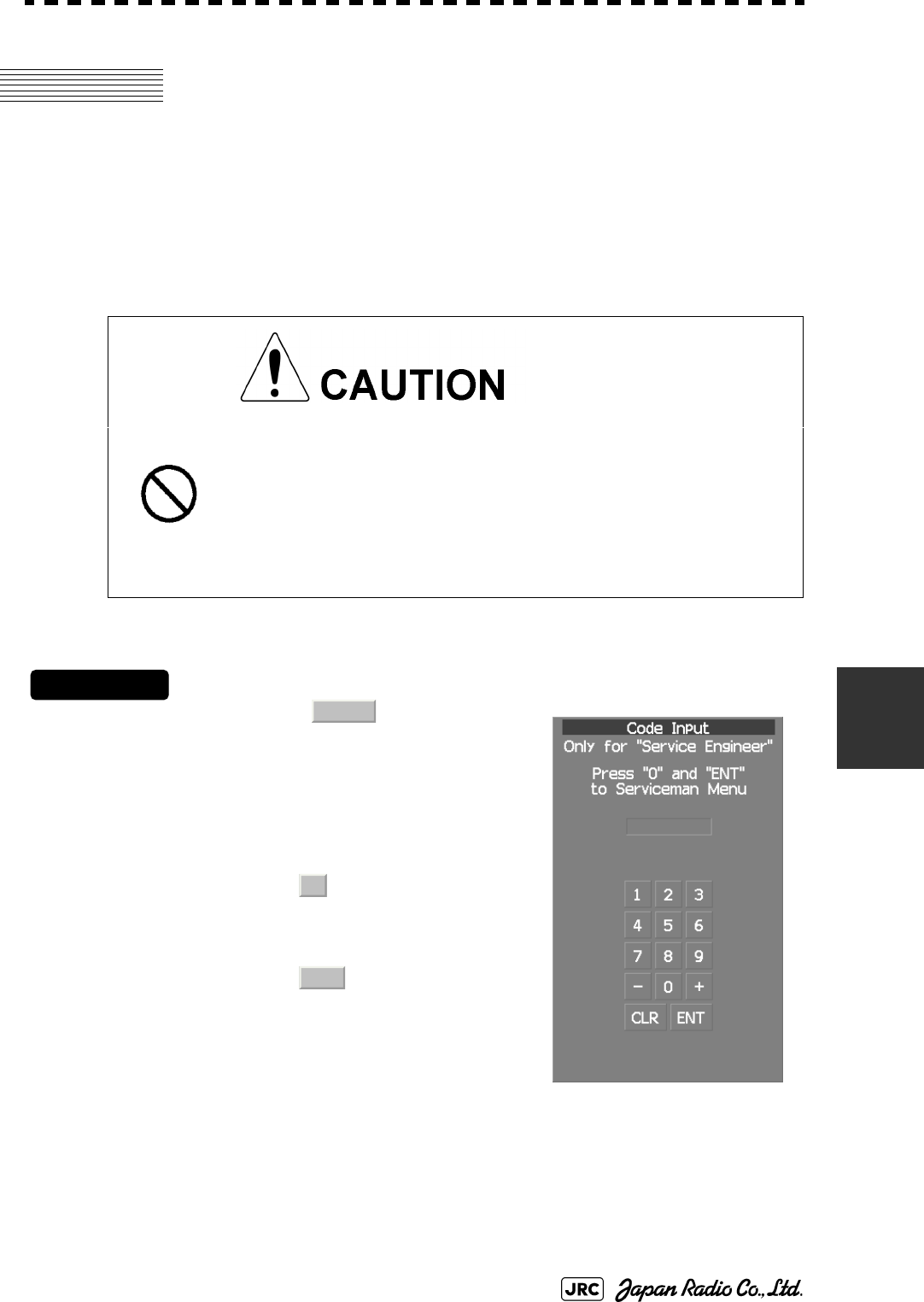
JMA-9100 Instruction Manual > 7.SETTINGS FOR SYSTEM OPERATION > 7.1 SETTINGS AT INSTALLATION
7-1
7
7.1 SETTINGS AT INSTALLATION
This section describes the electrical adjustment procedures to be performed by
service engineers during system installation.
The bearing adjustment value is saved to non-volatile memory in the scanner.
Other settings are saviedto non-volatile memory in the radar process unit.
7.1.1 How to Open the Serviceman Menu(Service Man Menu)
Procedures
1) Hold down the button at the
lower right of the display together
with the left key.
The Code Input menu will appear.
2) Left-click the button.
3) Left-click the button.
The Serviceman Menu will appear.
• Do not carry out the adjustments of the equipment
except authorized service persons. If wrong setting is
carried out, this may cause unstable operation.
• Do not carry out the adjustments during navigation.
Otherwise, the radar performance may be affected,
resulting in an accident or trouble.
Fig 7-1: Code Input
Main
0
ENT

7-2
JMA-9100 Instruction Manual > 7.SETTINGS FOR SYSTEM OPERATION > 7.1 SETTINGS AT INSTALLATION
7.1.2 GYRO I/F Setting
a. Gyro Settings (STEP or SYNC)
The GYRO I/F circuit of the system is designed to be compatible with most types
of gyro compasses by simply setting the switches.
Before power-on operation can be performed, the switches S1, S2, S5, S6, S7 and
jumper TB105 on the gyro interface circuit (PC4201) must be set in accordance
with the type of your gyro compass by performing the procedure below.
The switches are factory-set for a gyration ratio of 180X and the step motor type.
Make sure of the type of the gyro compass installed on the own ship before
starting the procedure below.
Procedures
1) Set S5 to "OFF".
The gyro compass and GYRO I/F are breaked off.
2) Set S6 and S7 in accordance with the type of your gyro compass.
There are two types of gyro compasses: one type outputs a step signal, and the other type
outputs a synchro signal. Make sure of the type of the gyro compass installed on the own
ship before setting the switches S6 and S7.
3) Set the DIP switch S1 in accordance with the type of the
compass.
The items to be set are listed below. For the settings, refer to Table 7-1: Gyro and
Log Select Switches (S1 DIP Switch).
Step motor type: DC24V to DC100V
Synchro-motor type: Primary excitation voltage 50 to 115 VAC
Synchro signal: Set the switches to [SYNC].
Step signal: Set the switches to [STEP].
S1-1: Type of gyro signal (step/synchro)
S1-2/3: Gyration ratio of gyro compass
S1-4: Gyration direction of gyro compass
S1-5: Type of log signal (pulse/synchro)
S1-7/8: Ratio of log signal

JMA-9100 Instruction Manual > 7.SETTINGS FOR SYSTEM OPERATION > 7.1 SETTINGS AT INSTALLATION
7-3
7
4) Set the DIP switch S2.
The items to be set are listed below. For the setting, refer to Table 7-2: Gyro and Log Select
Switches (S2 DIP Switch).
5) Confirm the settings of the DIP switch S10.
The DIP switch must be set as shown below. Do not change any of the settings.
6) Set the jumper TB105.
The TB105 is set for using a low-voltage step signal.
7) Connect the gyro signal and log signal cables to the terminal
block.
8) Set S5 to "ON".
The gyro compass and GYRO I/F are connected.
9) After power-on operation, make sure of the radar video and the
operation with the true bearing value.
See the Section 7.1.7 "Setting of True Bearing Value".
10) If the true bearing value of the radar equipment is reversed,
change the setting of the switch S1-4.
1 2 3 4 5 6 7 8
ON OFF OFF OFF ON OFF ON OFF
1 2 3 4 5 6 7 8
OFFOFFOFFOFFOFFOFFOFFOFF
1-2 connected: Setting for normal use
2-3 connected: Setting for a step signal of 22 V or less
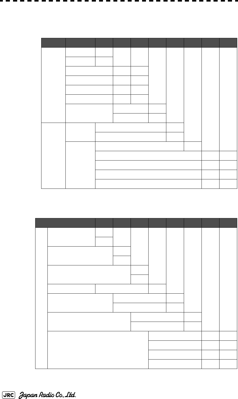
7-4
JMA-9100 Instruction Manual > 7.SETTINGS FOR SYSTEM OPERATION > 7.1 SETTINGS AT INSTALLATION
Table 7-1: Gyro and Log Select Switches (S1 DIP Switch)
12345678
GYRO SIG
STEP ON
SYNC OFF
360X OFF OFF
180X ON OFF
90X OFF ON
36X ON ON
DIRECTION REV ON
NOR OFF
LOG SIG
TYPE SYNC ON
PULSE OFF
PULSE/
NM
Don't care OFF
100P/30X ON ON
200P/90X OFF ON
400P/180X ON OFF
800P/360X OFF OFF
Table 7-2: Gyro and Log Select Switches (S2 DIP Switch)
S2 SETTING TABLE 12345678
OTHER SETTING
LOG ALARM ON
OFF
GYRO SIMULATOR ON
OFF
LOG SIMULATOR ON
OFF
N.A. Don't care any
GYRO ALARM TIME 5s ON
0.2s OFF
HEADING SENSOR SOURCE NMEA(HDT/THS) ON
GYRO SIGNAL OFF
NMEA BAUDRATE SETTING 4800 OFF OFF
9600 ON OFF
19200 OFF ON
38400 ON ON

JMA-9100 Instruction Manual > 7.SETTINGS FOR SYSTEM OPERATION > 7.1 SETTINGS AT INSTALLATION
7-5
7
7.1.3 Tuning (Tune Adjustment)
Adjust the tuning control for the transmitter and receiver.
The turning control should be adjusted when the system is installed or when the
magnetron is replaced.
Procedures
1) Set a range of 48 NM or more.
2) Open the Serviceman Menu.
3) Perform the following menu open procedure to open the Tune
Adjustment menu.
→
4) Adjust the tune adjustment value so that the tune indicator bar at
the upper left of the display is maximized.
For inputs to the value input screen, refer to Section 3.3.4.3 "Increasing or decreasing a
numeric value".
5) Move the cursor onto the button, and left-click .
7.1.3.1 Tune Indicator Adjustment)
Set the scale mark when the tune indicator bar reaches the maximum point.
Procedures
1) Set a range of 48 NM or more.
2) Open the Serviceman Menu.
3) Perform the following menu open procedure to open the Tune
Indicator Adjust menu.
→
→
1. Adjust Menu
1. Tune Adjustment
ENT
1. Adjust Menu
4. TXRX Adjustment
3. Tune Indicator Adjust

7-6
JMA-9100 Instruction Manual > 7.SETTINGS FOR SYSTEM OPERATION > 7.1 SETTINGS AT INSTALLATION
4) Adjust the tune indicator adjustment value by operating the
/ button so that the tune indicator bar at the upper
left of the display reaches a point of 80 to 90% of the maximum.
For inputs to the value input screen, refer to Section 3.3.4.3 "Increasing or decreasing a
numeric value".
5) Move the cursor onto the button, and left-click .
7.1.3.2 Tune Peak Adjustment
Adjust the tune indicator and echo peak.
Procedures
1) Set a range of 48 NM or more.
2) Open the Serviceman Menu.
3) Perform the following menu open procedure to open the Tune
Peak Adjustment menu.
→
→
4) Adjust the tune peak adjustment value by operating the /
button so that the tune indicator bar at the upper left of the
display is maximized.
For inputs to the value input screen, refer to Section 3.3.4.3 "Increasing or decreasing a
numeric value".
5) Move the cursor onto the button, and left-click.
With the NKE-2103 SCANNER UNIT:
For this model, perform Tune Peak Adjustment explained
below. After the above adjustment procedure, perform the
adjustment procedures below.
+-
ENT
i
1. Adjust Menu
4. TXRX Adjustment
2. Tune Peak Adjustment
+
-
ENT

JMA-9100 Instruction Manual > 7.SETTINGS FOR SYSTEM OPERATION > 7.1 SETTINGS AT INSTALLATION
7-7
7
7.1.4 Bearing Adjustment
Make adjustment so that the bearing of the target measured with the ship’s
compass matches the bearing of the target echo on the radar display.
Procedures
1) Select for the bearing presentation. Set video processing
(PROC) to .
2) Measure the bearing of an adequate target (e.g., a ship at anchor,
a breakwater, or a buoy) relative to own ship's heading.
3) Open the Serviceman Menu.
4) Perform the following menu open procedure to open the Bearing
Adjustment menu.
→
For inputs to the value input screen, refer to Section 3.3.4.3 "Increasing or decreasing a
numeric value".
Make adjustment by the 0.1°.
5) Adjust the bearing adjustment value by operating the /
button so that the target measured in step 2) is adjusted to
the correct bearing.
6) Left-click the button to determine the value.
7.1.5 Range Adjustment
Make adjustment so that the range of a target on the radar display is shown
correctly.
Procedures
1) Search the radar display for a target of which range is already
known.
2) Open the Serviceman Menu.
H Up
PROC Off
1. Adjust Menu
2. Bearing Adjustment
+
-
ENT

7-8
JMA-9100 Instruction Manual > 7.SETTINGS FOR SYSTEM OPERATION > 7.1 SETTINGS AT INSTALLATION
3) Perform the following menu open procedure to open the Range
Adjustment menu.
→
For inputs to the value input screen, refer to Section 3.3.4.3 "Increasing or decreasing a
numeric value".
4) Adjust the range adjustment value by operating the /
button so that the target measured in step 1) falls in the correct
range.
5) Left-click the button to determine the value.
7.1.6 Navigator Setting (Device)
Determine whether to connect navigators to the radar equipment.
Only the navigators set to ON here can be used.
Procedures
1) Open the Serviceman Menu.
2) Perform the following menu open procedure to open the Device
Installation menu.
→
→
3) Select for navigators connected to the radar equipment,
and for navigators not connected.
Gyro:Gyro (via GYRO I/F)
Compass:Compass (Compliant with IEC61162)
GPS Compass:GPS Compass (JRC)
LOG:Log (via GYRO I/F)
2AXW:2-axis log (Speed over water: Compliant with IEC61162)
2AXG:2-axis log (Speed over ground: Compliant with IEC61162)
GPS:GPS (Compliant with IEC61162)
1. Adjust Menu
3. Range Adjustment
+-
ENT
1. Adjust Menu
9. Next
3. Device Installation
On
Off

JMA-9100 Instruction Manual > 7.SETTINGS FOR SYSTEM OPERATION > 7.1 SETTINGS AT INSTALLATION
7-9
7
7.1.7 Setting of True Bearing Value
If GYRO I/F is used to input a gyro signal, the true bearing value indicated by the
master gyro does not match the value indicated by the radar equipment only in a
rare case. In this case, perform the following procedure to adjust the true bearing
value of the radar equipment to the value of the master gyro.
Procedures
1) Perform the following menu open procedure to open the true
bearing value setting menu.
→
→
2) Input the master gyro value to the value input screen.
For inputs to the value input screen, refer to Section 3.3.4.3 "Increasing or decreasing a
numeric value".
7.1.8 Antenna Height Setting (Antenna Height)
Set the height of radar antenna above sea level. Do not change this setting
carelessly.
Procedures
1) Measure the height of radar antenna above sea level in advance.
2) Open the Serviceman Menu.
3) Perform the following menu open procedure to open the Antenna
Height setting menu.
→
→
The Antenna Height menu will open.
4) Select the setting that matches the antenna height measured in
step 1).
Main
6. NAV Equipment Setting
1. Gyro Setting
1. Adjust Menu
4. TXRX Adjustment
1. Antenna Height

7-10
JMA-9100 Instruction Manual > 7.SETTINGS FOR SYSTEM OPERATION > 7.1 SETTINGS AT INSTALLATION
7.1.9 Setting of CCRP (CCRP Setting)
Set the own ship's CCRP location, radar antenna installation location, and GPS
installation location.
Procedures
1) Measure the CCRP location, radar antenna location, and GPS
antenna location in advance.
2) Open the Serviceman Menu.
3) Perform the following menu open procedure to open the CCRP
Setting menu.
→
4) Specify the ship length for Length at the upper right of the CCRP
Setting Menu, and the ship width for Beam.
5) Move the cursor onto the X, Y value, and left-click to
input the CCRP1 location.
When X > 0, the CCRP is on the starboard side of the ship.
When X < 0, it is on the port side.
6) To input the second CCRP, click the button to display the
CCRP2 X,Y value, and input the value in the same manner for
step 5).
Similarly, input the third and subsequent CCRPs.
7) Repeat the above steps to input the GPS location(s) and radar
antenna location(s).
8) If multiple CCRP locations and GPS locations are input, select
the CCRP location and GPS location to be used by pressing the
buttons at the upper left of the menu.
9) Click the to close the CCRP Setting menu.
CCRP:Up to four locations can be input. (One location selected when used)
Radar antenna: Up to eight radar antennas can be input. (Automatically selected in
response to ISW operation)
GPS:Up to four locations can be input. (One location selected when used)
2. Installation Menu
4. CCRP Setting
CCRP1
CCRP2
0.Exit
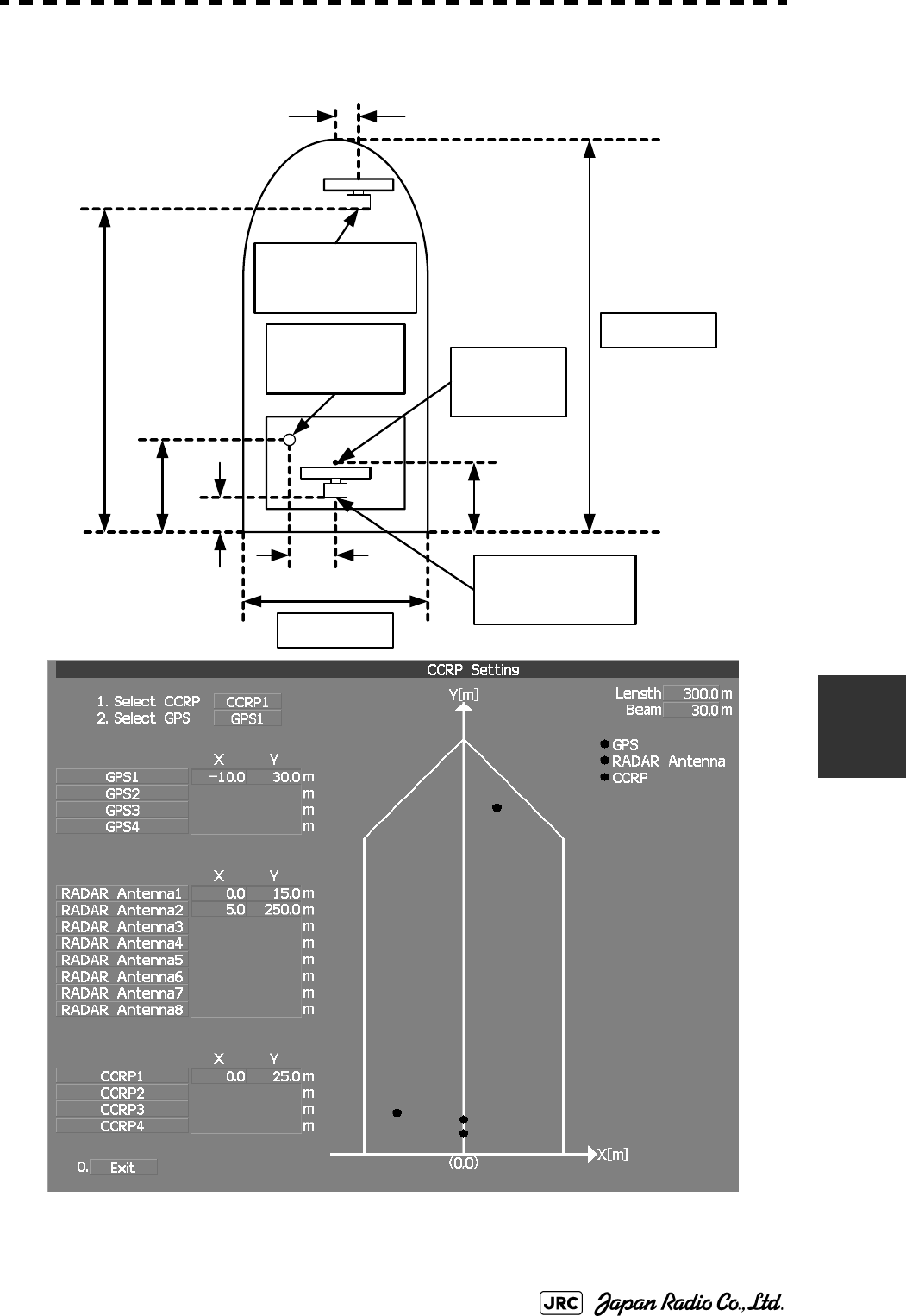
JMA-9100 Instruction Manual > 7.SETTINGS FOR SYSTEM OPERATION > 7.1 SETTINGS AT INSTALLATION
7-11
7
Length 300m
Beam 30m
RADAR Antenna1
X 0m, Y 15m
GPS1
X -10m, Y 30m
RADAR Antenna2
X 5m, Y 250m
30m
250 m
15m
10m
5m
25m
CCRP1
X 0m, Y 25m
Example:
7-12
JMA-9100 Instruction Manual > 7.SETTINGS FOR SYSTEM OPERATION > 7.2 SETTINGS
7.2 SETTINGS
This section describes the electrical adjustment procedures to be performed by
service engineers during system installation.
7.2.1 Communication Port Setting (COM Port Setting)
External sensor signals are input to the radar equipment through a communication
port. The radar equipment has ten communication ports. For signals to be input
from sensors or to be output to the sensors, communication ports need to be set in
accordance with the sensors.
7.2.1.1 Baud Rate Setting (Baud Rate)
Set the baud rate of the signal to be input to the COM port.
Procedures
1) Open the Serviceman Menu.
2) Perform the following menu open procedure to open the Baud
Rate setting menu.
→
→
• Do not carry out the adjustments of the equipment
except authorized service persons. If wrong setting is
carried out, this may cause unstable operation.
• Do not carry out the adjustments during navigation.
Otherwise, the radar performance may be affected,
resulting in an accident or trouble.
2. Installation Menu
5. COM Port Setting
1. Baud Rate

JMA-9100 Instruction Manual > 7.SETTINGS FOR SYSTEM OPERATION > 7.2 SETTINGS
7-13
7
3) Set the baud rate of the port to be set.
7.2.1.2 Reception Port Setting(RX Port)
Set the numbers of ports for receiving signals from sensors.
There are two methods for receiving signals: specifying a port for each sensor, or
using the automatic recognition function without specifying ports.
Procedures
1) Open the Serviceman Menu.
2) Perform the following menu open procedure to open the RX Port
setting menu.
→
→
3) Set a port for each sensor.
1. COMPASSa:
a. The compass port is a receive-only port that is dedicated to COMPASS signals.
4800(NMEA)/9600(NSK)/38400(fast NMEA)b bps
b. The bold values are factory-set.
2. MAINTENANCE/LOG:1200/4800/9600/38400 bps
3. NAV1:1200/4800/9600/38400 bps
4. NAV2:1200/4800/9600/38400 bps
5. ALARM:1200/4800/9600/38400 bps
6. JARPAc:
c. The JARPA port is a transmit-only port that is dedicated to JRC ARPA signals.
1200/4800/9600/38400 bps
7. AIS:1200/4800/9600/38400 bps
8. ARPAd:
d. The ARPA port is a transmit-only port.
1200/4800/9600/38400 bps
9. COM:1200/4800/9600/38400/115200 bps
Settable sensor
signals
GPS、DLOG、Alarm、Depth、Temperature、Wind、Current、
ROT、RSA
Selectable ports When the automatic recognition
function is used:
AUTO
When ports are specified: LOG、NAV1、NAV2、
ALARM、ARPA、COM
2. Installation Menu
5. COM Port Setting
2. RX Port

7-14
JMA-9100 Instruction Manual > 7.SETTINGS FOR SYSTEM OPERATION > 7.2 SETTINGS
7.2.1.3 Reception Sentence Setting (RX Sentence)
Set signal sentences to be received from sensors.
The system is factory-set for using all sentences. To receive only specified
sentences, select for sentences which are not necessary.
Procedures
1) Open the Serviceman Menu.
2) Perform the following menu open procedure to open the RX
Sentence setting menu.
→
→
3) Select the sentences to be used by the sensors to be set.
Selection value: or can be set for each sentence.
1. GPS(LL/COG/SOG):GGA/RMC/RMA/GNS/GLL/VTG
2. GPS(WPT/Time):GGA/RMC/RMB/BWC/BWR/ZDA
3. Depth:DPT/DBK/DBT/DBS
4. Wind:MWV/MWD
5. Current:
→Data Set Number:0-9. Set the number of the sentence to be used by Data
Set Number. (Initial value 0)
→Layer A:Set the number of the sentence to be used with layer A
by Layer Number. (Initial value 3)
→Layer B:Set the number of the sentence to be used with layer B
by Layer Number. (Initial value 4)
→Layer C:Set the number of the sentence to be used with layer C
by Layer Number. (Initial value 5)
No Use
2. Installation Menu
5. COM Port Setting
3. RX Sentence
Use
No Use

JMA-9100 Instruction Manual > 7.SETTINGS FOR SYSTEM OPERATION > 7.2 SETTINGS
7-15
7
7.2.1.4 Transmission Port Setting (TX Port)
For each sentence, set a communication port through which signals are
transmitted to sensors.
Procedures
1) Open the Serviceman Menu.
2) Perform the following menu open procedure to open the TX Port
setting menu
→
→
3) Select the communication port through which the sentence to be
set is output.
4) Select the output format, talker, and transmission interval.
Signals for which the above items can be set:
Settable sentences TTM(TT)、TLL(TT)、TTD(TT)、TLB(TT)、OSD、RSD、ALR、
ACK、TTM(AIS)、TLL(AIS)、TTD(AIS)、TLB(AIS)、
RemoteMaintenance、JRC-ARPA、APB、BOD、GGA、GLL、
RMC、RMB、VTG、XTE、BWC、HDT、THS
Selectable ports MAINTENANCE、NAV1、NAV2、ALARM、JARPA、ARPA、
COM
Item Name Option
NMEA0183
Output Format
APB, BOD, GGA,
GLL, RMC, RMB,
VTG, XTE, BWC,
HDT
V1.5
V2.0
V2.3a
a. The bold values are factory-set.
NMEA0183
Talkerb
b. For TTM, TLL, OSD, RSD, and ALR, the talker is always RA .
For GGA, GLL, RMC, and VTG, the talker is always GP.
APB, BOD,RMB,
XTE, BWC, HDT,
THS
STANDARD:The talker is RA .
GP:The talker is GP.
NMEA0183 TX
Interval
APB, BOD, GGA,
GLL, RMC, RMB,
VTG, XTE, BWC,
HDT, THS
Set an interval in the range 1 to 9 seconds.
2. Installation Menu
5. COM Port Setting
4. TX Port

7-16
JMA-9100 Instruction Manual > 7.SETTINGS FOR SYSTEM OPERATION > 7.2 SETTINGS
7.2.2 Sector Blank Setting (Sector Blank)
In order not to display radar echoes, set a sector range and stop transmission in the
bearing range. Three types of sectors can be created.
The sector blank function operates in the relative bearing with the bow as the
benchmark.
7.2.2.1 Sector Blank Function On/Off (Sector1,2 and 3)
Procedures
1) Open the Serviceman Menu.
2) Perform the following menu open procedure to open the Sector
Blank setting menu.
→
3) Set the sector blank number , , or with
which the sector blank function operates.
The system allows the use of up to three sector blank areas.
Set each sector blank area to on or off.
7.2.2.2 Sector Blank Area Creation (Make Sector 1,2,3)
Procedures
1) Open the Serviceman Menu.
2) Perform the following menu open procedure to open the Sector
Blank setting menu.
→
3) Select the sector blank number ( to ) for
sector creation, and click the Make Sector button in the menu.
The selected sector blank will be made.
: The sector blank function of the number is operated.
: The sector blank function of the number is stopped.
2. Installation Menu
3. Sector Blank
Sector 1 Sector 2 Sector 3
On
Off
2. Installation Menu
3. Sector Blank
Make Sector 1 Make Sector 3

JMA-9100 Instruction Manual > 7.SETTINGS FOR SYSTEM OPERATION > 7.2 SETTINGS
7-17
7
4) Set the starting azimuth of the sector blank by operating the
[EBL] dial, and left-click the button.
The start angle of the sector blank will be set.
5) Set the ending azimuth of the sector blank by operating the [EBL]
dial, and left-click the button.
The end angle of the sector blank will be set.
7.2.3 TNI Blank Setting (TNI Blank)
Set a sector range and stop tuning operation in the bearing range.
If a structure such as the mast is close to the radar antenna, automatic tuning
operation may become unstable. In this case, set a TNI blank in the direction of
the structure in order to stabilize the tuning operation.
Only one type of a sector can be created. The TNI blank function operates in the
relative bearing with the bow as the benchmark.
7.2.3.1 TNI Blank Function On/Off (Sector)
Procedures
1) Open the Serviceman Menu.
2) Perform the following menu open procedure to open the TNI
Blank setting menu.
→
→
3) Select the item in the menu, and turn on or off the TNI
blank function.
7.2.3.2 TNI Blank Area Creation (Make Sector)
Procedures
1) Open the Serviceman Menu.
: The TNI blank function is operated.
: The TNI blank function is stopped.
ENT
ENT
2. Installation Menu
9. Next
2. TNI Blank
1. TNI Blank
On
Off

7-18
JMA-9100 Instruction Manual > 7.SETTINGS FOR SYSTEM OPERATION > 7.2 SETTINGS
2) Perform the following menu open procedure to open the Sector
Blank setting menu.
→
→
3) Left-click the button in the menu.
The selected sector blank will be made.
4) Set the starting azimuth of the TNI blank by operating the [EBL]
dial, and left-click the button.
The start angle of the TNI blank will be set.
5) Set the ending azimuth of the TNI blank by operating the [EBL]
dial, and left-click the button.
The end angle of the TNI blank will be set.
7.2.4 Setting of Bearing Pulses from Scanner Unit (Output Pulse)
Set the output value of bearing pulses from the scanner unit. The system can set
2048 pulses or 4096 pulses. This setting is enabled only when the scanner unit of
25 or 30 kW is used.
Procedures
1) Open the Serviceman Menu.
2) Perform the following menu open procedure to open the Output
Pulse setting menu.
→
→
3) Set the number of pulses to be output by the scanner unit.
a
a. If a 10 kW antenna is used, 2048 is always set.
:2048 pulses per antenna rotation (Recommended value)
:4096 pulses per antenna rotation
2. Installation Menu
9. Next
2. TNI Blank
2. Make Sector
ENT
ENT
1. Adjust Menu
4. TXRX Adjustment
6. Output Pulse
2048
4096
JMA-9100 Instruction Manual > 7.SETTINGS FOR SYSTEM OPERATION > 7.2 SETTINGS
7-19
7
7.2.5 Slave Mode Setting (Master/Slave)
Place the system in the Slave mode when it is to be operated as the sub-display
that displays radar echoes by using radar signals from other radar equipment.
The input value of externally input bearing pulses can be set. The system can set
2048 pulses or 4096 pulses.
7.2.5.1 Slave Mode Setting (Master/Slave)
Procedures
1) Open the Serviceman Menu.
2) Perform the following menu open procedure to open the
installation setting menu.
3) Select Slave for the item in the menu.
7.2.5.2 Setting of Input Bearing Pulse (Input BP Pulse)
Procedures
1) Open the Serviceman Menu.
2) Perform the following menu open procedure to open the second
page of the installation setting menu.
→
3) Set the number of pulses for the item in the
menu.
:The system operates as radar equipment while the own
antenna is connected.
:The system operates as a sub-display while the signal
cable of other radar equipment is connected.
:2048 pulses per antenna rotation
:4096 pulses per antenna rotation
2. Installation Menu
2. Master Slave
Master
Slave
2. Installation Menu
9. Next
1. Input BP Count
2048
4096

7-20
JMA-9100 Instruction Manual > 7.SETTINGS FOR SYSTEM OPERATION > 7.2 SETTINGS
7.2.6 Language Setting (Language)
The system is designed to switch between display languages, Japanese and
English.
Procedures
1) Open the Serviceman Menu.
2) Perform the following menu open procedure to open the
language setting menu.
→
3) Select the language to be used.
7.2.7 Date Time Setting
To display time, the local time, local date, and time-zone difference must be set.
However, if the "ZDA" sentence of NMEA0183 is received, time can be
automatically displayed.
Procedures
1) Perform the following menu open procedure to open the
language setting menu.
→
→
The Date Time Setting menu will open.
2) Set information about date and time
2)-1. UTC/LMT (Time display system)
a
a. Other is an option to display character strings created by our overseas agents.
Ask the overseas agent or our sales department if your language is supported. To
determine the selected language, turn the power off, and then turn it on.
: Universal Time Coordinate
: Local Mean Time
2. Installation Menu
8. Language
1. English
2. Japanese
3. Other
Main
7. Sub Menu
6. Date Time Setting
UTC
LMT

JMA-9100 Instruction Manual > 7.SETTINGS FOR SYSTEM OPERATION > 7.2 SETTINGS
7-21
7
2)-2. LMT Date
Input the date in local time.
2)-3. LMT Time
Input the date in local time.
2)-4. Time Zone
Input the time-zone difference between the universal time and local time.
2)-5. Display Style
2)-6. Synchronize with GPS
7.2.8 Input Installation Information
The system can input installation information.
Procedures
1) Open the Serviceman Menu.
2) Perform the following menu open procedure to open the
language setting menu.
→
3) Input the installation information.
For the input method on the numeric value and character input screens, see Section 3.3.4
"Operation on Numeric Value, Latitude / Longitude and Character Input menu".
Set one of the following date display formats.
例:2007-12-31
例:DEC 31, 2007
例:31 DEC, 2007
A ZDA sentence sent by the GPS is used, thereby displaying time
synchronized with the GPS time.
a:
a. If On is selected for this item but a ZDA sentence is not input, the system
internal clock function is used to display the date and time.
Time synchronized with the GPS time
:Time not synchronized with the GPS time
Input the date of installed system.
Input the name of installation personel.
Input the name of radar installer.
YYYY-MM-DD
MMM DD, YYYY
DD MMM, YYYY
On
Off
Main
1. Installation Information
Date
Name
Company

7-22
JMA-9100 Instruction Manual > 7.SETTINGS FOR SYSTEM OPERATION > 7.2 SETTINGS
7.2.9 Setting the Alarm System
7.2.9.1 Setting the reset interval (Reset Interval)
This function enables the control of WMRST terminal (on the terminal board
circuit).The reset signal is turned on when operation in a set period of time.
Procedures
1) Open the Serviceman Menu.
2) Perform the following menu open procedure to open the Reset
Interval menu.
→
→
→
3) Input the value to be set.
For how to input numeric data on the numeric value input screen, see Section 3.3.4
"Operation on Numeric Value, Latitude / Longitude and Character Input menu".
7.2.9.2 Setting the Trackball Threshold
This function enables the control of WMRST terminal (on the terminal board
circuit).
The reset signal is turned off when trackball is moved, that caused by vibration.If
trackball move distance go over the threshold (dot unit) when reset signal is
turned on.
Procedures
1) Open the Serviceman Menu.
2) Perform the following menu open procedure to open the
Trackball Threshold menu.
→
→
→
3) Input the value to be set.
For how to input numeric data on the numeric value input screen, see Section 3.3.4
"Operation on Numeric Value, Latitude / Longitude and Character Input menu".
2. Installation Menu
6. Alarm System
1. Watch Alarm
1. Reset Interval
2. Installation Menu
6. Alarm System
1. Watch Alarm
2. Trackball Threshold

JMA-9100 Instruction Manual > 7.SETTINGS FOR SYSTEM OPERATION > 7.2 SETTINGS
7-23
7
7.2.9.3 Setting the relay output (Relay Output)
This function enables the control of ARPAALM terminal (on the terminal board
circuit).
Procedures
1) Open the Serviceman Menu.
2) Perform the following menu open procedure to open the Relay
Output menu.
→
→
3) Left-click the button in the menu.
The Relay Output mode is switched.
4) Click the item button corresponding to the item to be changed.
The item can be turned on / off.
7.2.9.4 Setting the ALR output (ALR Output)
This function enables the control of ALR port (See Section 7.2.1 "Communication
Port Setting (COM Port Setting)").
Procedures
1) Open the Serviceman Menu.
: The output is continuously controlled.
: The output is intermittenly controlled.
: The relay output is turned on when alarm have issued.
: The relay output is not turned on when alarm have issued.
: There is a dangerous target. (tracked target)
: There is a dangerous target. (AIS target)
: A new target is acquired in the automatic acquisition zone.
: There is a lost target. (Target Tracking / AIS).
2. Installation Menu
6. Alarm System
2. Relay Output
1. Relay Output Mode
Continuous
Intermittent
On
Off
2. TT CPA/TCPA
3. AIS CPA/TCPA
4. New Target
5. Lost

7-24
JMA-9100 Instruction Manual > 7.SETTINGS FOR SYSTEM OPERATION > 7.2 SETTINGS
2) Perform the following menu open procedure to open the ALR
Output menu.
→
→
3) Click the item button corresponding to the item to be changed.
The item is turned on / off.
7.2.9.5 Setting the External Acknowledgement (External ACK Setting)
This function enables the control of system when ACK sentence have received.
Procedures
1) Open the Serviceman Menu.
2) Perform the following menu open procedure to open the External
ACK Setting menu.
→
→
3) Click the item button corresponding to the menu to be changed.
: The ALR sentence is output when alarm have issued.
: The ALR sentence is not output when alarm have issued.
: The internal alarm.
: Target Tracking Alarms and AIS Function Alarms.
:CPA/TCPA alarm.
:Exept Critical Alarm.
2. Installation Menu
6. Alarm System
2. Relay Output
On
Off
1. System Alarm
2. TT/AIS Alarm
2. Installation Menu
6. Alarm System
5. External ACK Setting
Critical Alarm
Normal Alarm
JMA-9100 Instruction Manual > 7.SETTINGS FOR SYSTEM OPERATION > 7.2 SETTINGS
7-25
7
4) Click the item button corresponding to the item to be changed.
The item is switched.
7.2.9.6 Setting the Alarm Buzzer (Sound Output Mode)
This function enables the control of alarm buzzer.
Procedures
1) Open the Serviceman Menu.
2) Perform the following menu open procedure to open the External
ACK Setting menu.
→
→
3) Select the function to be used.
, and
Setting and Ararm Function
①: Followed by Buzzer Volume menu setting.
②: Alarm Buzzer is turned off.
③: If Relay Output menu is turned on when Alam Buzzer is turned off. If Relay Output menu is turned off when Alam
Buzzer is turned on.
For how to setting Buzzer Volume menu, see Section 3.8.6 "Adjust Sound Volume (Buzzer Volume)".
: Setting of alarm sound.
→: The alarm sound is not stopped when
acknowridgement have received.
→: The alarm sound is stopped when
acknowridgement have received.
: Setting of alarm indication.
→: The alarm indication brinking is stopped when
acknowridgement have received.
→: The alarm indication brinking is not stopped
when acknowridgement have received.。
: Setting of ALR sentence.
→: Add acknowridgement to ALR sentence.
→: Add no acknowridgement (unrecognized) to ALR
sentence.
Alarm Setting Operation Operation
Miss CPA/
TCPA
New
Target
Lost NAV System ISW
①
①②
①③①②①
Audio
On
Off
Indication
Lightning
Brinking
Acknowledge State
A;ACK
V;UNACK
2. Installation Menu
6. Alarm System
4. Sound Output Mode
On
Off 1 Off 2
On
Off 1
Off 2
7-26
JMA-9100 Instruction Manual > 7.SETTINGS FOR SYSTEM OPERATION > 7.3 ADJUSTMENT
7.3 ADJUSTMENT
This section describes the electrical adjustment procedures to be performed by
service engineers during system installation.
7.3.1 Noise Level Adjustment (Noise Level)
7.3.1.1 Noise Level Adjustment for Signal Processing
Procedures
1) Open the Serviceman Menu.
2) Perform the following menu open procedure to open the noise
level adjustment menu.
→
→
3) Increase/decrease the noise level adjustment value.
The noise level is factory-set. (Initial value: 140)
After system installation, a great change in the noise level adjustment value should be
avoided; it should be fine adjusted within ±5.
Do not carry out the adjustments of the equipment
except authorized service persons. If wrong setting is
carried out, this may cause unstable operation.
Do not carry out the adjustments during navigation.
Otherwise, the radar performance may be affected,
resulting in an accident or trouble.
9. RADAR/TT Initial Setup
1. Signal Processing
1. Echo Noise Level

JMA-9100 Instruction Manual > 7.SETTINGS FOR SYSTEM OPERATION > 7.3 ADJUSTMENT
7-27
7
7.3.1.2 Noise Level Adjustment Mode (Setting Mode)
A noise level is factory-adjusted while this mode is turned on.
Procedures
1) Open the Serviceman Menu.
2) Perform the following menu open procedure to open the noise
level adjustment menu.
→
→
The noise level adjustment mode is switched between on and off.
7.3.2 Adjustment of Target Tracking Function (TT)
7.3.2.1 Vector Constant Adjustment (Vector Constant)
Adjust the vector follow-up performance of the target tracking function.
The vector constant is adjusted to an optimal value, so do not change it carelessly.
Procedures
1) Open the Serviceman Menu.
2) Perform the following menu open procedure to open the Vector
Constant adjustment menu.
Factory-adjustment method
・The noise level adjustment value is once decreased to about 130.
・While the noise level adjustment value is gradually increased, the value
with which radar echoes start turning yellow is determined as the set
value.
・The noise level adjustment mode is turned off when the adjustment is
finished.
Do not change the set value carelessly.
The vector constant shall be set to 5 normally. If the vector
constant value is higher, a target’s vector will be better followed
up when the target and own ship change their course or speed,
but the vector accuracy will be lower on the contrary.
9. RADAR/TT Initial Setup
1. Signal Processing
2. Setting Mode
Attention
7-28
JMA-9100 Instruction Manual > 7.SETTINGS FOR SYSTEM OPERATION > 7.3 ADJUSTMENT
→
→
The window for setting vector constants will appear.
3) Input the value to be set.
For how to input numeric data on the numeric value input screen, see Section 3.3.4
"Operation on Numeric Value, Latitude / Longitude and Character Input menu".
7.3.2.2 Quantization Level Adjustment (Video TD Level)
Use the target tracking function (TT) to adjust the level of the signal to be
recognized as a target. If a small value is set, even weak target signals will be
input to the target detection circuit of the target tracking function. However, many
unnecessary signals are also input, which may cause unstable target acquisition or
tracking. It is important to set a value four or five greater than the value with
which unnecessary signals are detected.
The quantization level is adjusted to an optimal value, so do not change it
carelessly.
Procedures
1) Open the Serviceman Menu.
2) Perform the following menu open procedure to open the target
tracking setting menu.
→
3) To change the quantization level of the automatic acquisition
area, specify the item in the menu. To change
the quantization level of tracking and manual acquisition, specify
the item .
4) Input the value to be set.
Do not change the set quantization level carelessly. If
the level deviates from the proper value, the target
acquisition and tracking functions will deteriorate.
Otherwise, this may cause accidents.
9. RADAR/TT Initial Setup
2. TT
1. Vector Constant
9. RADAR/TT Initial Setup
2. TT
2. Video TD Level
3. Video High Level
JMA-9100 Instruction Manual > 7.SETTINGS FOR SYSTEM OPERATION > 7.3 ADJUSTMENT
7-29
7
7.3.3 Main Bang Suppression Level Adjustment (MBS)
Main Bang Suppression is adjusted to suppress main bang, a reflection signal
from 3D circuit including wave guide tube, that generally appears as a circular
image focusing on the center of the radar display. Optimum adjustment allows
main bang image to remain lightly on the display.
7.3.3.1 Adjustment of Main Bang Suppression Level (MBS Level)
Procedures
1) Open the Serviceman Menu.
2) Perform the following menu open procedure to open the MBS
level adjustment menu.
→
→
3) Set the radar as follows:
•Set the radar range to 0.125 NM.
•Set the radar video enhance function (ENH) to OFF.
•Set the image processing (PROC) to OFF.
•Turn the [RAIN] control to the minimum position (fully to the left).
•Turn the [GAIN] control to the maximum position (fully to the right).
•Turn the [SEA] control to achieve the strength with which main bang can be judged.
4) Adjust the value so that the main bang can be erased.
Do not change this adjusted level carelessly.
Incorrect adjustment may erase targets in point-blank
range and cause collision, resulting in death or serious
injury.
9. RADAR/TT Initial Setup
3. MBS
1. MBS Level

7-30
JMA-9100 Instruction Manual > 7.SETTINGS FOR SYSTEM OPERATION > 7.3 ADJUSTMENT
7.3.3.2 Adjustment of Main Bang Suppression Area (MBS Area)
Procedures
1) Open the Serviceman Menu.
2) Perform the following menu open procedure to open the MBS
Area adjustment menu.
→
→
3) Set the radar as follows:
•Set the radar range to 0.125 NM.
•Set the radar video enhance function (ENH) to OFF.
•Set the image processing (PROC) to OFF.
•Turn the [RAIN] control to the minimum position (fully to the left).
•Turn the [GAIN] control to the maximum position (fully to the right).
•Turn the [SEA] control to achieve the strength with which main bang can be judged.
4) Adjust the value so that the main bang can be erased.
9. RADAR/TT Initial Setup
3. MBS
2. MBS Area
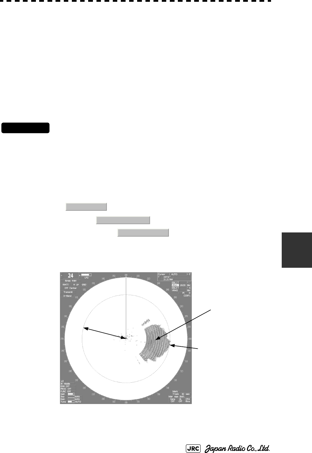
JMA-9100 Instruction Manual > 7.SETTINGS FOR SYSTEM OPERATION > 7.3 ADJUSTMENT
7-31
7
7.3.4 Adjustment of Performance Monitor
After replacement of either of the following units, adjust the performance monitor
according to the procedures in this section:
•Performance monitor
•Antenna unit
7.3.4.1 Transmission Monitor Adjustment (MON Adjustment)
Adjust the circuit for monitoring the transmission performance of the radar
equipment.
Procedures
1) If the performance monitor is equipped with an inter-switch
function, set it as the master display unit.
2) Open the Serviceman Menu.
3) Perform the following menu open procedure to open the
Performance Monitor Adjustment menu.
→
→
4) Increase or decrease the adjustment value so that the farthest
point of the performance monitor pattern touches the 18.0 nm
line on the chart.
Fig 7-2: MON Adjustment
1. Adjust Menu
4. TXRX Adjustment
4. MON Adjustment
18.00NM Increase or decrease the
adjustment value so that the
farthest point of the
Performance Monitor pattern
contacts the 18.0 nm line.
Performance Monitor pattern
7-32
JMA-9100 Instruction Manual > 7.SETTINGS FOR SYSTEM OPERATION > 7.3 ADJUSTMENT
7.3.4.2 Reception Monitor Adjustment (MON Indicator Adjustment)
Adjust the circuit for monitoring the reception performance of the radar
equipment.
Procedures
1) If the performance monitor is equipped with an inter-switch
function, set it as the master display unit.
2) Open the Serviceman Menu.
3) Perform the following menu open procedure to open the
performance monitor Indicator Adjustment menu.
→
→
4) Increase or decrease the adjustment value so that the
performance monitor level indicator will be adjusted to "8".
5) Attach the INFORMATION LABEL provided with the performance
monitor to an appropriate position on the display unit.
6) Write the performance monitor bar value check date to the
INFORMATION LABEL.
During performance monitor adjustment, all acquisitions by the
target tracking function are released.
The released target acquisitions are not recovered.
1. Adjust Menu
4. TXRX Adjustment
4. MON Adjustment
MON
JMA-9100 Instruction Manual > 7.SETTINGS FOR SYSTEM OPERATION > 7.4 MAINTENANCE MENU
7-33
7
7.4 MAINTENANCE MENU
This item is provided for equipment maintenance, including settings of antenna
safety switch, master reset, etc.
7.4.1 Antenna Safety Switch (Safety Switch)
Use this switch to measure the transmission/reception performance while the
antenna is in stopped state.
Procedures
1) Open the Serviceman Menu.
2) Perform the following menu open procedure to open the Safety
Switch setting menu.
→
3) Select the item to be set.
Set operation when the antenna safety switch is turned off.
4) Change the setting back to when the work is finished.
Only our service engineers are to make the
adjustment. Neglecting this caution may cause
accidents and failures.
Do not make the adjustments during navigation.
Otherwise, adjustments may affect the radar functions,
causing accidents and failures.
:The transmitter stops transmission. The screen on the
display unit remains in transmission state.
:(Normal setting) The transmitter stops transmission. The
screen on the display unit is placed in standby state.
:The transmitter continues transmission. The screen on the
display unit remains in transmission state. In this case,
however, an error such as a bearing signal failure occurs
because the safety switch is turned off.
3. Maintenance Menu
1. Safety Switch
1. TX-OFF
2. Standy
3. TX-ON
2. Standy

7-34
JMA-9100 Instruction Manual > 7.SETTINGS FOR SYSTEM OPERATION > 7.4 MAINTENANCE MENU
7.4.2 Initialization of Memory Area(Area Initial)
If system operation is unstable, it may be stabilized by initializing the memory
area. To initialize the memory area, follow the procedure in this section. The
memory area is reset to the factory setting when initialized.
7.4.2.1 Partial Master Reset
Procedures
1) Open the Serviceman Menu.
2) Perform the following menu open procedure to open the Partial
Master Rest operation menu for the memory area.
→
→
3) Select the items to be initialized.
4) Select in the Confirmation Menu.
The memory areas of specified items are initialized, and the system is restarted.
7.4.2.2 All Master Reset
Procedures
1) Open the Serviceman Menu.
2) Perform the following menu open procedure to open the All
Master Rest operation menu for the memory area.
→
→
3) Select in the Confirmation Menu.
The whole memory area is initialized, and the system is restarted.
:The set values in the Serviceman menu are initialized.
:The set values not in the Serviceman menu are initialized.
:The user-set values are initialized.
:The set values for the target tracking function are initialized.
:The set values for the AIS display function are initialized.
:The color scheme and brilliance setting for the day/night
mode are initialized.
3. Maintenance Menu
2. Area Initial
1. Partial Master Reset
1. Serviceman Menu
2. Except Serviceman Menu
3. User Setting
4. TT Setting
5. AIS Setting
6. Day/Night
1. Yes
3. Maintenance Menu
2. Area Initial
2. All Master Reset
1. Yes

JMA-9100 Instruction Manual > 7.SETTINGS FOR SYSTEM OPERATION > 7.4 MAINTENANCE MENU
7-35
7
7.4.3 Save of Internal Memory Data (Card1/2)
The system can save internal memory data such as item settings in all menus onto
a flash memory card. If the radar processing circuit in the system has been
replaced, the set values before the circuit replacement can be restored by reading
the set values you saved before the replacement.
To save the internal memory data onto a flash memory card (option), the card
must be inserted in card slot beforehand.
7.4.3.1 Copying of Internal Settings onto Card (Internal To Card1/2)
Save the internal memory data, such as item settings in menus, onto a flash memory card.
The internal memory data should be saved at completion of system setting, and the operation
condition should be saved periodically.
Procedures
1) Open the Serviceman Menu.
2) Perform the following menu open procedure to open the Internal
to Card2 menu.
→
3) Select in the Confirmation Menu.
The internal memory data is saved on the flash memory card.
7.4.3.2 Reading of Internal Settings from Card (Card1/2 To Internal)
Read the saved memory data from the flash memory card into the system memory.
Perform the read operation in order to return the system to the previous operation condition
after replacement of the radar processing circuit in the system.
Procedures
1) Open the Serviceman Menu.
2) Perform the following menu open procedure to open the Card2 to
Internal menu.
→
3) Select in the Confirmation Menu.
The memory data is read from the flash memory card into the system memory.
After the internal memory area is updated, the system is restarted.
3. Maintenance Menu
3. Internal To Card2
1. Yes
3. Maintenance Menu
4. Card2 To Internal
1. Yes

7-36
JMA-9100 Instruction Manual > 7.SETTINGS FOR SYSTEM OPERATION > 7.4 MAINTENANCE MENU
7.4.4 Restoration of Scanner Unit Operation Time (TXRX Time)
The system adds up the following operation time and contains it in the scanner
unit:
•Transmission time
•Motor run time
Clear the above total time when the magnetron or scanner unit motor is replaced.
7.4.4.1 Clear of Motor Run Time (Clear TX Time)
Clear the scanner's motor run time.
Perform the following procedure to clear the motor run time when the scanner motor is
replaced.
Procedures
1) Open the Serviceman Menu.
2) Perform the following menu open procedure to open the Clear
Motor Time menu.
→
→
3) Select in the Confirmation Menu.
The motor run time in the TXRX's internal control circuit is cleared to 0.
7.4.4.2 Save of Antenna Time (Clear Motor Time)
Save the following scanner unit time data from the scanner unit into the display unit.
Perform the following procedure to inherit the scanner unit time data when the TXRX's
internal control circuit is replaced.
Procedures
1) Open the Serviceman Menu.
2) Perform the following menu open procedure to open the Clear
Motor Time menu.
→
→
3) Select in the Confirmation Menu.
The motor run time in the TXRX's internal control circuit is cleared to 0.
3. Maintenance Menu
5. TXRX Time
1. Clear TX Time
1. Yes
3. Maintenance Menu
5. TXRX Time
2. Clear Motor Time
1. Yes

JMA-9100 Instruction Manual > 7.SETTINGS FOR SYSTEM OPERATION > 7.4 MAINTENANCE MENU
7-37
7
7.4.4.3 Save of Scanner Unit Time (TXRX To Display Unit)
Save the following scanner unit time data from the scanner unit into the display unit.
Perform the following procedure of 7.4.4.4 to inherit the scanner unit time data when the
TXRX's internal control circuit is replaced.
Procedures
1) Open the Serviceman Menu.
2) Perform the following menu open procedure to open the TXRX to
Display Unit menu.
→
→
3) Select in the Confirmation Menu.
The scanner unit time data in the TXRX's internal control circuit is saved transferred to the
display unit.
7.4.4.4 Restoration of Antenna Time (Display Unit To TXRX)
Restore the antenna time data from the display unit into the antenna's internal control circuit.
Perform the above procedure of 7.4.4.3 to inherit the antenna time data when the antenna's
internal control circuit is replaced.
Procedures
1) Open the Serviceman Menu.
2) Perform the following menu open procedure to open the Display
Unit to TXRX menu.
→
→
3) Select in the Confirmation Menu.実行確認画面で、 を選択
する。
The scanner unit time data in the display unit is restored transferred to the antenna's internal
control circuit.
3. Maintenance Menu
5. TXRX Time
3. TXRX To Display Unit
1. Yes
3. Maintenance Menu
5. TXRX Time
4. Display Unit To TXRX
1. Yes

7-38
JMA-9100 Instruction Manual > 7.SETTINGS FOR SYSTEM OPERATION > 7.4 MAINTENANCE MENU
7.4.5 Update of Character String Data (String Data Update)
The system is designed to transfer and display external character strings as the
second language display. The second language is factory-set to "Japanese."
Ask our agent or sales department for the supply of character strings to be
updated.
To update character strings, the flash memory card (option) containing the
character string file must be inserted in card slot 2.
Procedures
1) Open the Serviceman Menu.
2) Perform the following menu open procedure to open the String
Data Update menu.
→
3) Select in the Confirmation Menu.
The character string file on the flash memory card is read into the system, and the second
language area is updated.
To display the read character strings in the second language, select Other in the menu
shown in Section 7.2.6 "Language Setting (Language)".
3. Maintenance Menu
6. String Data Update
1. Yes
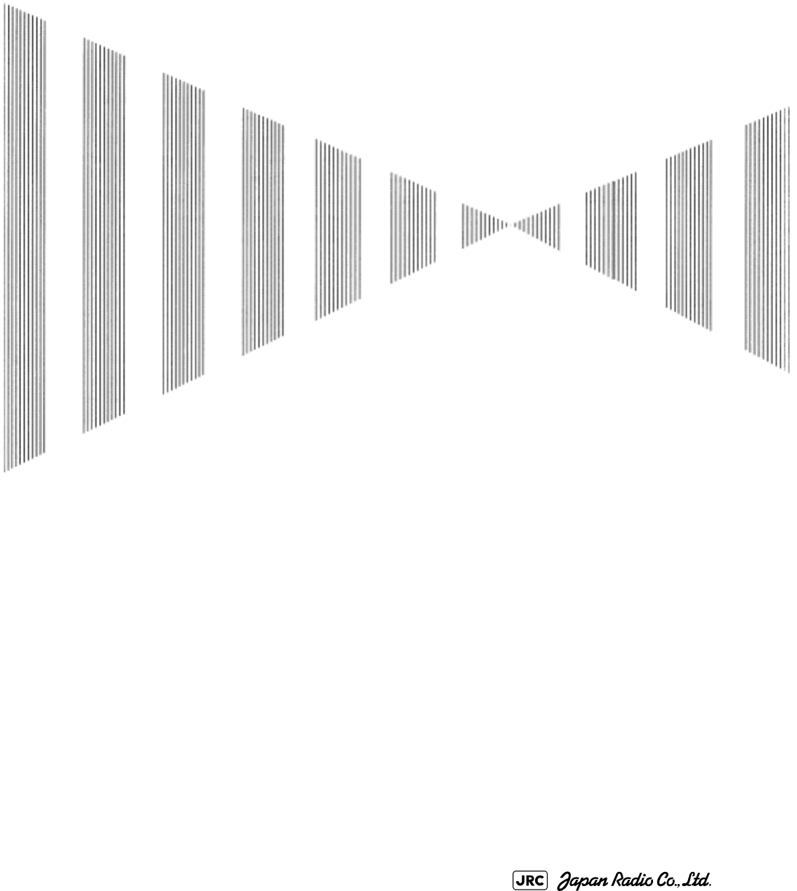
COUNTERMEASURES FOR TROUBLE AND ADJUSTMENT
8.1 ROUTINE MAINTENANCE ....................................................................8-1
8.2 MAINTENANCE ON EACH UNIT ...........................................................8-2
8.2.1 Scanner Unit NKE-1125/1129/1130/1139/2103/2254 ....................8-2
8.2.2 Wave Guide Tube (JMA-9123-7XA/9XA) ........................................8-4
8.2.3 Coaxial Cable (JMA-9133-SA) ........................................................8-4
8.2.4 Transmitter Receiver Unit (NTG-3225/3230) ................................8-5
8.2.5 Display Unit (NCD-4990) ................................................................8-5
8.3 PERFORMANCE CHECK ......................................................................8-6
8.3.1 Check Performance on Test Menu ...............................................8-6
8.3.1.1 Self-diagnosis function (Self Test) ............................................8-7
8.3.1.2 Monitor Test ................................................................................8-9
8.3.1.3 Operation Unit Test (Keyboard Test) .......................................8-9
8.3.1.4 Check of the Performance Monitor (MON Display) ...............8-10
8.3.1.5 System Alarm Log display .......................................................8-10
8.3.1.6 System Information ..................................................................8-11
8.3.1.7 Magnetron Current ....................................................................8-11
8.4 REPLACEMENT OF MAJOR PARTS ..................................................8-12
SECTION 8
COUNTERMEASURES FOR TROUBLE
AND ADJUSTMENT
8.4.1 Parts Required for Periodic Replacement ..................................8-13
8.4.2 Replacement of magnetron ..........................................................8-13
8.4.2.1 Scanner Unit NKE-1130 ............................................................8-14
8.4.2.2 Scanner Unit NKE-2254, NKE-1125 .......................................8-16
8.4.2.3 Scanner Unit NKE-2103 .........................................................8-19
8.4.2.4 Transmitter Receiver Unit NTG-3230 ....................................8-21
8.4.2.5 Transmitter Receiver Unit NTG-3225 ....................................8-24
8.4.3 Replacement of Motor ...................................................................8-28
8.4.3.1 Scanner Unit NKE-1139/1130 ................................................8-28
8.4.3.2 Scanner Unit NKE-1125/2254 ................................................8-30
8.4.3.3 Scanner Unit NKE-2103 .........................................................8-31
8.4.4 Replacement of LCD Monitor .......................................................8-33
8.4.4.1 Display Unit NCD-4990 .............................................................8-33
8.4.5 Replacement of Backup Battery ..................................................8-36
8.4.5.1 About the Battery Alarm ...........................................................8-36
8.4.5.2 How to Replacement of Backup Battery .................................8-36
JMA-9100 Instruction Manual > 8.COUNTERMEASURE FOR TROUBLE ... > 8.1 ROUTINE MAINTENANCE
8-1
8
8.1 ROUTINE MAINTENANCE
For operating the radar equipment in the good conditions, it is necessary to make
the maintenance work as described below. If maintenance is made properly,
troubles will reduce. It is recommended to make regular maintenance work.
Common points of maintenance for each unit are as follow:
•Clean the equipment.
Remove the dust, dirt, and sea water rest on the equipment cabinet with a piece of
dry cloth.
Especially, clean the air vents with a brush for good ventilation.
• Never carry out internal inspection or repair work of the
equipment by users. Inspection or repair work by
unauthorized personnel may result in fire hazard or
electric shock. Ask the nearest branch, business office or
a dealer for inspection and repair.
• Turn off the main power before maintenance work.
Otherwise, an electric shock may result.
• Turn off the main power before cleaning the equipment.
Especially, make sure to turn off the indicator if a rectifier
is used. Otherwise, equipment failure, or death or serious
injury due to electric shock may result, because voltage is
outputted from the rectifier even when the radar is not
operating.
8-2
JMA-9100 Instruction Manual > 8.COUNTERMEASURE FOR TROUBLE ... > 8.2 MAINTENANCE ON EACH UNIT
8.2 MAINTENANCE ON EACH UNIT
8.2.1 Scanner Unit NKE-1125/1129/1130/1139/2103/2254
a. Precautions in Mounting the Cover
When the cover is removed for regular checkup and replacement of parts and
refitted after such work, the procedures of fastening bolts shall be taken with the
following precautions:
1) The proper fastening torque of the fitting bolts (M8) is 1176 to 1470 N/
cm (120 to 150kgf/cm) (which makes the inside water-tight and protects
the packings against permanent compressive strain).The packings
start producing from the cover at a torque of approximately 1470N/cm
(150kgf/cm). Do not fasten the bolts with a torque exceeding the
specified value. Otherwise, the screws may be broken.
2) Use an offset wrench of 11 mm X 13 mm or a double-ended wrench of
13 mm X 17 mm (not longer than 200 mm).
3) Screw all the bolts by hand first to prevent them playing, then fasten
them evenly in order not to cause one-sided fastening. (Fasten the
bolts with 25% of the required torque at the first step.)
• Turn off the main power source before starting
maintenance. Otherwise, an electric shock or injury
may be caused.
• Do not touch the radiator. Even if the power is turned
off, the radiator may be rotated by the wind.
• Turn "OFFi" the safety switch to stop the scanner unit.
(Refer to Section 1.4 "EXTERIOR DRAWINGS".)
Otherwise, you may be injured if touching the rotating
scanner unit by accident.
i. After the work, turn "ON" the scanner unit safety switch.
• Do not touch the radiator. Even if the power is turned
off, the radiator may be rotated by the wind.
*Fasten the bolts in the diagonal order.
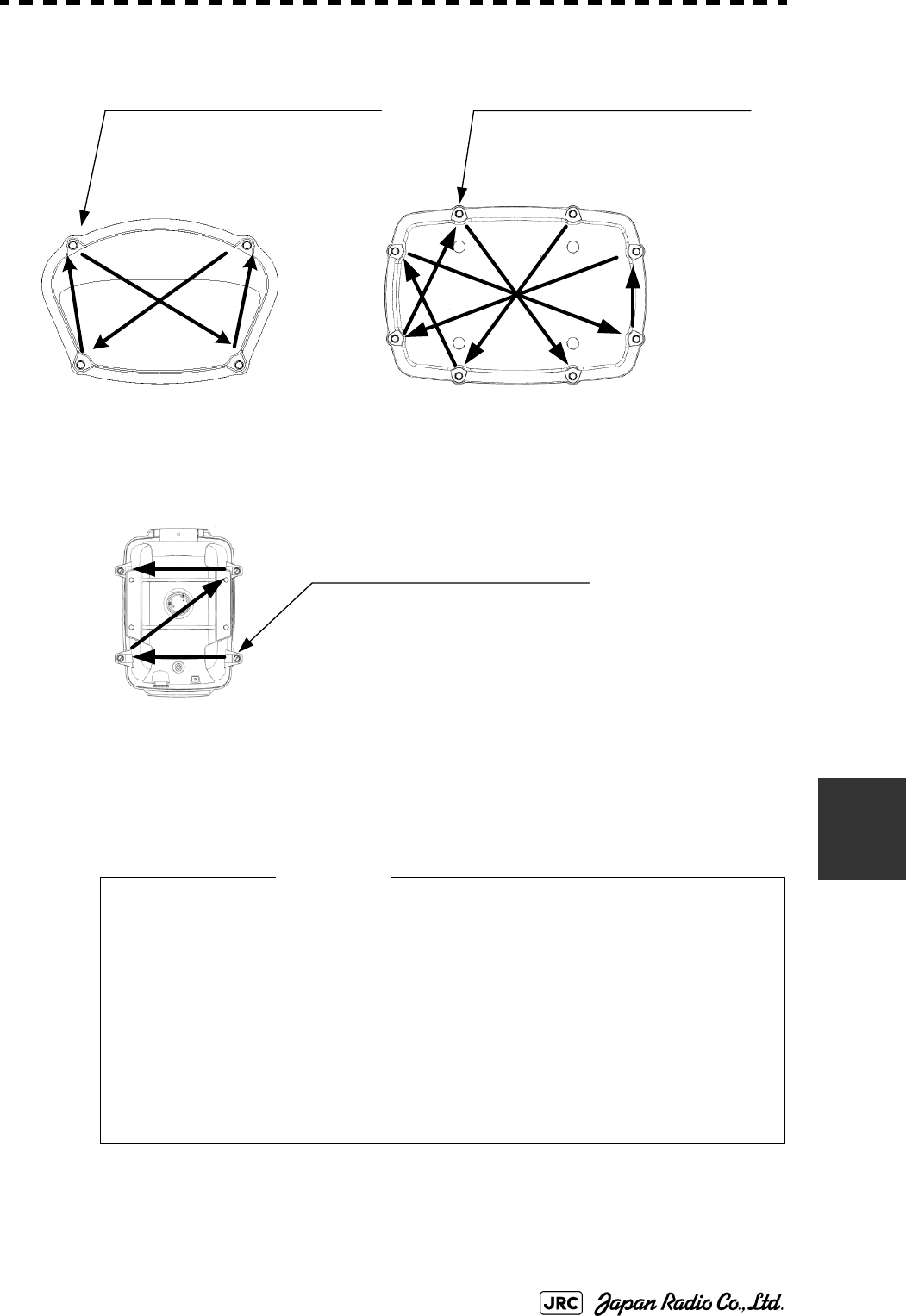
JMA-9100 Instruction Manual > 8.COUNTERMEASURE FOR TROUBLE ... > 8.2 MAINTENANCE ON EACH UNIT
8-3
8
b. Radiator
Check up and clean the radiator.
• If the radiator front face (radiation plane) is soiled with smoke,
salt, dust, paint or birds’ droppings, wipe it with a piece of soft
cloth wetted with alcohol or water and try to keep it clean at all
times. Otherwise, radar beam radiation may attenuate or reflect
on it, resulting in deterioration of radar performance.
• Never use solvents of gasoline, benzine, trichloroethylene and
ketone for cleaning. Otherwise, the radiation plane may
deteriorate.
②
①
③
④
⑤
⑥
⑦
⑧
Tightening torque : 120 to 150 kgf/cm
4-M8 (stainless steel) bolt
Tightening torque : 120 to 150 kgf/cm
8-M8 (stainless steel) bolt
②
①③
④
②①
③④
Bolt Tightening Procedure of
NKE-1125/1129/2254 Cover
Bolt Tightening Procedure of
NKE-1130 /1139 Cover
Bolt Tightening Procedure of
NKE-2103 Cover
Tightening torque : 120 to 150 kgf/cm
4-M8 (stainless steel) bolt
Attention

8-4
JMA-9100 Instruction Manual > 8.COUNTERMEASURE FOR TROUBLE ... > 8.2 MAINTENANCE ON EACH UNIT
c. Rotating section
c-1 Supply Oil Seal
When there is not a grease nipple, the replenishment of grease oil is unnecessary.
Remove the cap on the grease nipple located on the side of the X band radar or on
the front of S band radar at which the radiator is supported, and grease with a
grease gun.Make the oiling every six months. The oil quantity shall be
approximately 100 g, which is as much as the grease comes out of the oil seal.
Use the grease of Mobilux 2 of Mobil Oil.
c-2 Oiling gears
Apply grease evenly to the tooth surfaces of the main shaft drive gear and the
encoder drive gear with a spreader or brush. Oiling in short intervals is more
effective to prevent the gears from wear and tear and extend their service life, but
oil at least every six months.
Use Mobilux2 of Mobile Oil.
c-3 Mounting legs
Check the mounting legs and mounting bolts of the antenna unit case for corrosion
at intervals and maintain them to prevent danger. Apply paint to them once a half
year because painting is the best measure against corrosion.
8.2.2 Wave Guide Tube (JMA-9123-7XA/9XA)
8.2.3 Coaxial Cable (JMA-9133-SA)
The coaxial tube gland of a coaxial cable terminal is fully waterproofed when
installed. To prevent a water leakage accident, periodically inspect the coaxial
tube gland. In particular, the coaxial tube gland should be repainted every six
months.
• Install wave guide tubes without any clearance. Leaving a
clearance may cause water leakage or corrosion later.
Attention
JMA-9100 Instruction Manual > 8.COUNTERMEASURE FOR TROUBLE ... > 8.2 MAINTENANCE ON EACH UNIT
8-5
8
For details, refer to the coaxial cable installation procedure for S-band radars.
8.2.4 Transmitter Receiver Unit (NTG-3225/3230)
Wipe dust off the transmitter and receiver with a dry cloth or feather duster.
8.2.5 Display Unit (NCD-4990)
Dust accumulated on the screen will reduce clarity and darken the video. For
cleaning it, wipe it with a piece of soft cloth (flannel or cotton).
Do not wipe it strongly with a piece of dry cloth nor use gasoline or thinner.
• Do not apply strong shock to the coaxial cable by
striking it with a tool or hammering it. Otherwise, an
open circuit failure may result.
• Do not place anything heavy on the coaxial
cable.Otherwise, an open circuit failure may result.
• Do not twist or pull the coaxial cable.
• When cleaning the screen, do not wipe it too strongly
with a dry cloth. Also, do not use gasoline or thinner to
clean the screen. Otherwise the screen surface may be
damaged
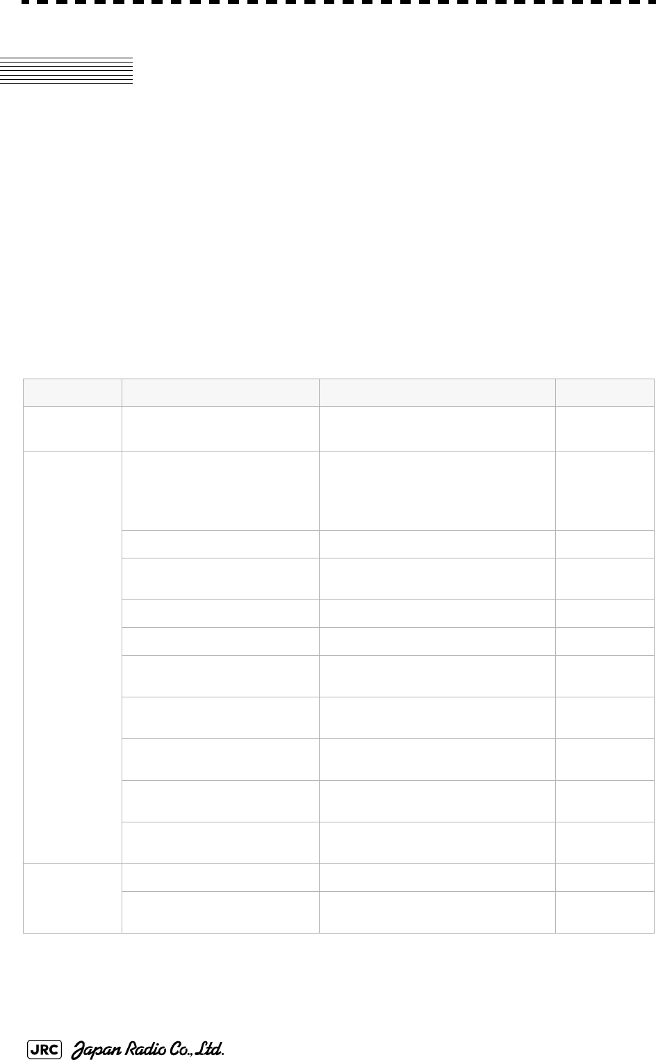
8-6
JMA-9100 Instruction Manual > 8.COUNTERMEASURE FOR TROUBLE ... > 8.3 PERFORMANCE CHECK
8.3 PERFORMANCE CHECK
Make operational check on the radar equipment regularly and if any problem is
found, investigate it immediately. Pay special attention to the high voltage
sections in checking and take full care that no trouble is caused by any error or
carelessness in measurement. Take note of the results of checking, which can be
used effectively in the next check work.
Operational check shall be made in accordance with Table 8-1 Function Check
List in the order as specified in it.
8.3.1 Check Performance on Test Menu
The radar operating state can be checked by opening the Test Menu.
Table8-1: Performance Check List
Equipment Item to be checked Criteria Remarks
Transmitter
Receiver Unit
Tuning LED of Receiver The LED is lighting during operation 48NM range
Display Unit Video and echoes on the screen Sensitivity
LCD brilliance can be controlled correctly
Various markers
Various numerical indications
Lighting
Can be correctly controlled
Memory See the Section [1] "Memory Test"
Communications Lines See the Section [3] "Check of
Communication Lines (Line Test)"
Power Supply, Backup Battery See the Section [4] "Supply Voltage"
Monitor See the Section 8.3.1.2 "Monitor Test"
Operation Unit See the Section 8.3.1.3 "Operation Unit
Test (Keyboard Test)"
System Alarm Log Display See the Section 8.3.1.5 "System Alarm
Log display"
System Information Display See the Section 8.3.1.6 "System
Information"
Magnetron current See the Section 8.3.1.7 "Magnetron
Current"
Target Tracking See the Section 5.2.7 "Operation Test
(TT Test Menu)"
Scanner Unit Signals from the Scanner Unit See the Section [2] "TXRX Test"
Performance Monitor See the Section 8.3.1.4 "Check of the
Performance Monitor (MON Display)"
JMA-9100 Instruction Manual > 8.COUNTERMEASURE FOR TROUBLE ... > 8.3 PERFORMANCE CHECK
8-7
8
Procedures
1) Perform the following menu open procedure to open the Test
Menu.
→
2) Select the items to be checked.
The list of check items will appear.
8.3.1.1 Self-diagnosis function (Self Test)
Check of memory, scanner unit, and communications Lines
[1] Memory Test
Checks for the performance of built-in memory.
When no abnormality is found, OK is displayed. When an abnormality is found, NG is
displayed.
8.3.1.1Self-diagnosis function (Self Test)
8.3.1.2Monitor Test
8.3.1.3Operation Unit Test (Keyboard Test)
8.3.1.4Check of the Performance Monitor (MON Display)
8.3.1.5System Alarm Log display
8.3.1.6System Information
8.3.1.7Magnetron Current
[1]Memory Test
[2]TXRX Test
[3]Check of Communication Lines (Line Test)
[4]Supply Voltage
SDRAM Check
SRAM Check
FLASH ROM Check
GRAPHIC Check
Main
9. Test Menu
1. Self Test
2. Monitor Test
3. Keyboard Test
4. MON Display
5. System Alarm Log
6. System Information
Magnetron Current
1. Memory Test
2. TXRX Test
3. Line Test
4. Supply Voltage
1. SDRAM
2. SRAM
3. FLASH ROM
4. GRAPHIC
8-8
JMA-9100 Instruction Manual > 8.COUNTERMEASURE FOR TROUBLE ... > 8.3 PERFORMANCE CHECK
[2] TXRX Test
Checks for signals from the scanner.
When no abnormality is found, OK is displayed. When an abnormality is found, NG is
displayed.
In standby, ** will appear.
[3] Check of Communication Lines (Line Test)
Check the status of communications with options.
When no abnormality is found, OK is displayed. When an abnormality is found, NG is
displayed.
The status display field of equipment not connected is left blank.
[4] Supply Voltage
Check the voltage of internal power supply.
Scanner's safety switch check
Scanner rotation signal check
Heading line signal check
Check on the load current of high voltage in
the modulator
Radar trigger signal check
Radar video check
Check on connection with the transmitter-receiver
Check on connection with the signal processing circuit
Check on connection with the target tracking unit
Check on connection with the GYRO I/F unit
Check on connection with the interswitch
Item Normal value
12V 11.4 to 12.6V
5V 4.75 to 5.25V
3.3V 3.14 to 3.46V
Battery 2.5V or more
Safety Switch
AZI Pulse
HL Pulse
MH Current
Trigger
Video
TXRX
SIG. PROC
TT
GYRO I/F
ISW

JMA-9100 Instruction Manual > 8.COUNTERMEASURE FOR TROUBLE ... > 8.3 PERFORMANCE CHECK
8-9
8
8.3.1.2 Monitor Test
Checks for the display.
The test pattern will be shown on the display.
To return to the normal display, press any key.
If errors occur in the monitor, no test pattern will appear.
8.3.1.3 Operation Unit Test (Keyboard Test)
Checks for the controls and switches of the operation panel.
[1] Key Test
Checks for the controls and switches of the operation panel.
Each key on the operation panel on the display is shown in reverse video at the
same time the key is pressed, and the name of the pressed key is displayed.
[2] Buzzer Test
Checks for the operation panel buzzer.
The buzzer will sound. The buzzer automatically stops after it sounds for a
specified length of time.
[3] Light Test
Checks for the control panel light.
The brightness of the operation panel is gradually intensified at four levels.
:All colors are filled with white.
:A white box is displayed on the black background of 1280
×1024dot.
:Displays rectangle X 2, circle X 2, and cross-shape X13
(white lines on the black background).
:Displays “H” of 9 dots X 9 dots on the entire screen (white
character on the black background).
:Gray scale display (16 levels)
:Displays a color bar.
:Displays the VDR test pattern.
:Displays the specified color.
[1]Key Test
[2]Buzzer Test
[3]Light Test
1. Pattern1
2. Pattern2
3. Pattern3
4. Pattern4
5. Pattern5
6. Pattern6
7. Pattern7
8. Pattern8
1. Key Test
2. Buzzer Test
3. Light Test
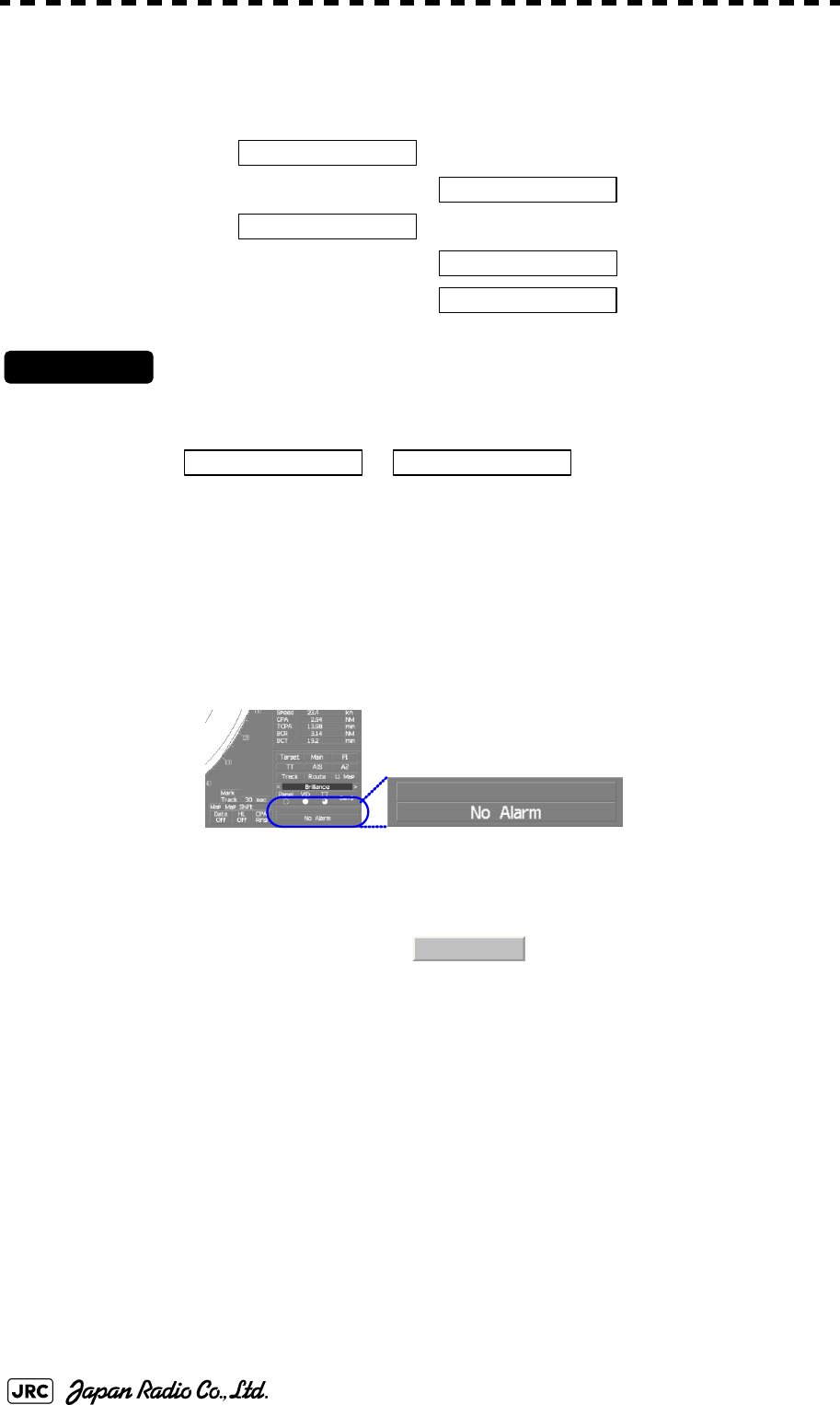
8-10
JMA-9100 Instruction Manual > 8.COUNTERMEASURE FOR TROUBLE ... > 8.3 PERFORMANCE CHECK
8.3.1.4 Check of the Performance Monitor (MON Display)
Displays the performance monitor status.
Procedures
1) Turn the [VRM] dial to make adjustments so that the farthest
point of the performance monitor pattern.
The of is displayed.
8.3.1.5 System Alarm Log display
Displays previously occurred system errors with the dates and times when they
occurred.
The current error is displayed at the lower right of the radar display. For details,
refer to Section 9.1.1 "List of Alarms and other Indications".
The Error log display button (page2-31 Alarm) is clicked, in the same way as that
one.
To erase the alarm logs, press the button in the log display window.
Transmitter system attenuation value check.
→
Receiver system attenuation value check.
→
→
*Transmitter System
Attenuation Value
*Receiver System
MON Pattern Range
Attenuation Value
Attenuation Value *Receiver System
All Clear
JMA-9100 Instruction Manual > 8.COUNTERMEASURE FOR TROUBLE ... > 8.3 PERFORMANCE CHECK
8-11
8
8.3.1.6 System Information
Displays the current system information.
8.3.1.7 Magnetron Current
マDisplays the Magnetron Current bar indicating the magnetron current to check.
When a 48 NM range is set, the magnetron current is normal if the Magnetron
Current bar reads the value below.
Processor software version information
Scanner software version information
System number
Total magnetron transmitting time (Total time
during which radar was transmitted)
→
→
Total operating time (Total power-on time)
Total operating time of the scanner unit (Total
power-on time of the scanner unit)
Total operating time of the display unit (Total
power-on time of the display unit)
10kW : 4 to 6 scale marks
25/30kW : 6 to 9 scale marks
Indicator
TXRX
System No.
TX Time
X-Band
S-Band
Motor Time
TXRX Total Time
Total Time
8-12
JMA-9100 Instruction Manual > 8.COUNTERMEASURE FOR TROUBLE ... > 8.4 REPLACEMENT OF MAJOR PARTS
8.4 REPLACEMENT OF MAJOR PARTS
The system includes parts that need periodic replacement. The parts should be
replaced as scheduled. Use of parts over their service life can cause a system
failure.
• Turn off the main power source before replacing parts.
Otherwise, an electric shock or trouble may be caused.
• Before replacing the magnetron, turn off the main
power source and wait for 5 minutes or more until the
high voltage circuits are discharged. Otherwise, an
electric shock may be caused.
• Take off your wrist watch when bringing your hands
close to the magnetron. Otherwise, your watch may be
damaged because the magnetron is a strong magnet.
• Two or more persons shall replace the liquid crystal
monitor. If only one person does this work, he may
drop the LCD, resulting in injury.
• Even after the main power source is turned off, some
high voltages remain for a while. Do not contact the
inverter circuit in the LCD with bare hands. Otherwise,
an electric shock may be caused.
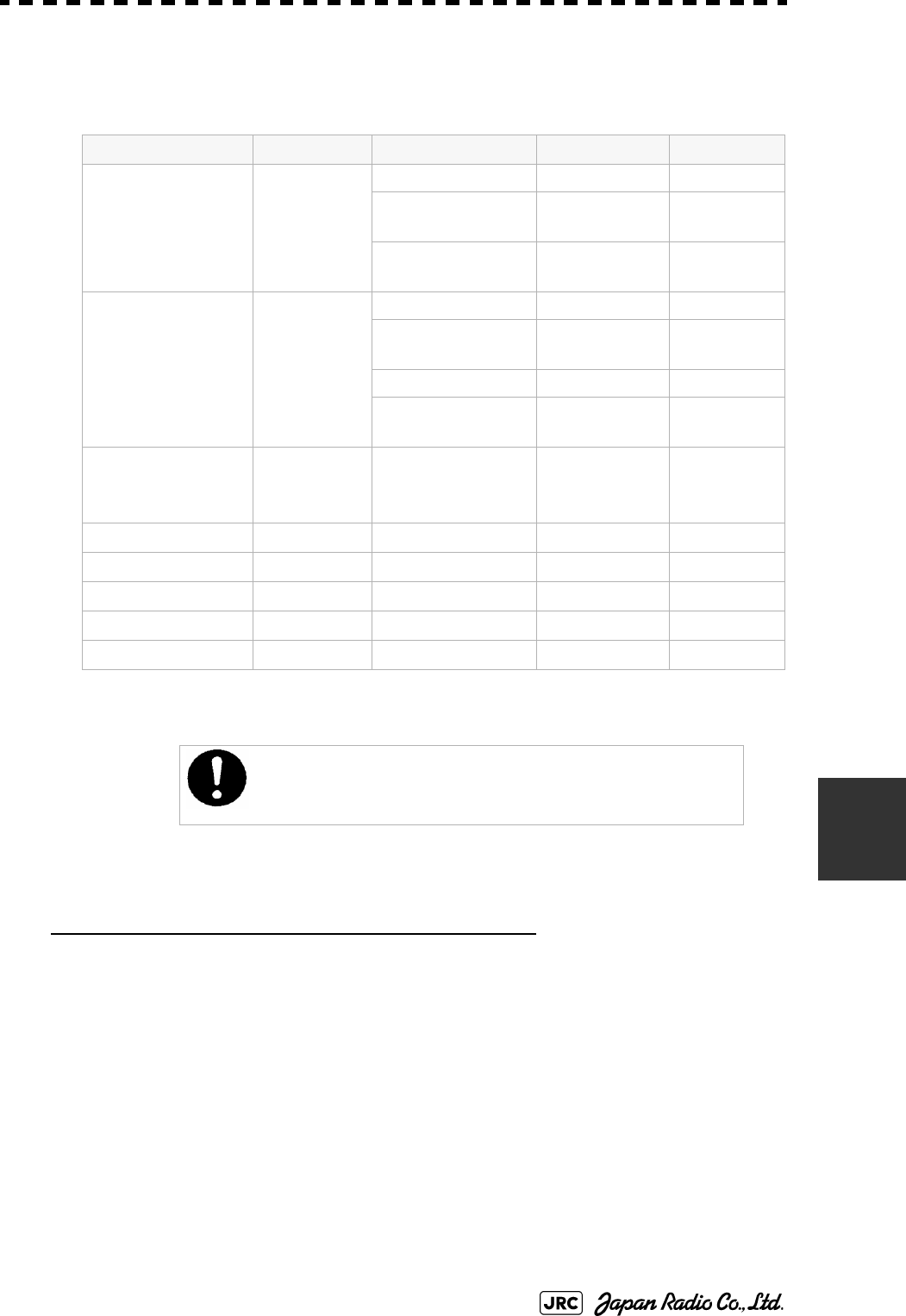
JMA-9100 Instruction Manual > 8.COUNTERMEASURE FOR TROUBLE ... > 8.4 REPLACEMENT OF MAJOR PARTS
8-13
8
8.4.1 Parts Required for Periodic Replacement
Here are parts required for periodic replacement
8.4.2 Replacement of magnetron
When mounting a new magnetron, do not touch the magnet with a screwdriver or
put it on an iron plate. After replacement, connect the lead wire correctly.
Handling of Magnetron under Long-Time Storage
The magnetron that has been kept in storage for a long time may cause sparks and
operate unstably when its operation is started. Perform the aging in the following
procedures:
1) Warm up the cathode for a longer time than usually. (20 to 30 minutes
in the STBY state.)
2) Start the operation from the short pulse range and shift it gradually to
the longer pulse ranges. If the operation becomes unstable during this
process, return it to the standby mode immediately. Keep the state for
5 to 10 minutes until the operation is restarted.
Part name Interval Radar model Part type Part code
1. Magnetron 4,000 hours JMA-9110-6XA/6XAH 5VMAA00102 5VMAA00102
JMA-9122-6XA/9XA/6XAH
JMA-9123-7XA/9XA
5VMAA00106 5VMAA00106
JMA-9132-SA
JMA-9133-SA
5VMAA00104 5VMAA00104
2. Motor 10,000 hours JMA-9110-6XA/6XAH 7BDRD0048 7BDRD0048
JMA-9122-6XA/9XA
JMA-9123-7XA/9XA
MDBW10822 MDBW10822
JMA-9122-6XAH 7BDRD0045A 7BDRD0045A
JMA-9132-SA
JMA-9133-SA
MDBW10823 MDBW10823
3. Fan (Scanner Unit) 20,000 hours JMA-9110-6XA/6XAH
JMA-9122-6XA/9XA/6XAH
JMA-9132-SA
7BFRD0002 7BFRD0002
4. LCD PANEL 50,000 hours 7WSRD0002A 7WSRD0002A
5. Fan
(Radar Process Circuit) 20,000 hours 109R0612S4D13 5BFAB00588
(Power Supply) 20,000 hours H-7BFRD0006 7BFRD0006
7. Backup battery 5 years 5ZBCJ00012 5ZBCJ00012
Replacement of magnetron must be made by specialized
service personnel.
For details, refer to Service Manual.
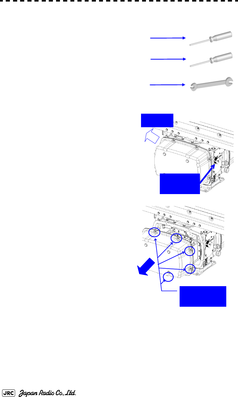
8-14
JMA-9100 Instruction Manual > 8.COUNTERMEASURE FOR TROUBLE ... > 8.4 REPLACEMENT OF MAJOR PARTS
8.4.2.1 Scanner Unit NKE-1130
[Required tools]
•
A Phillips screwdriver for 4 mm screw
•
A Phillips screwdriver for 6 mm screw
•
A wrench (width across flats 13 mm, for M8 screws)
[Replacement procedure]
1)
Before starting part replacement work, turn
off the safety switch of the scanner unit.
The safety switch is located on the rear
(stern) side. Remove the cover and turn off
(to the lower side) the safety switch.
2)
Remove the pedestal cover.
Make sure that there is no foreign matter or
dust adhered to the gasket when you put
the cover on.
Bow side
Turn off the
safety switch.
Remove the eight
hexagonal screws.
Removing the port side cover
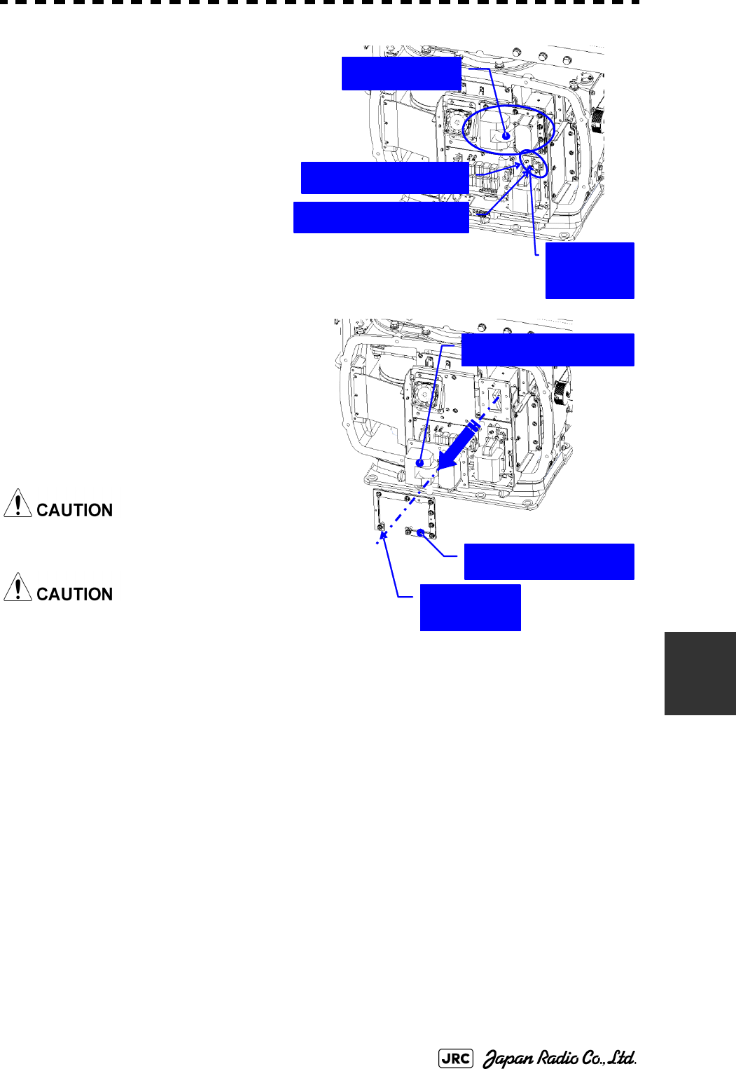
JMA-9100 Instruction Manual > 8.COUNTERMEASURE FOR TROUBLE ... > 8.4 REPLACEMENT OF MAJOR PARTS
8-15
8
3)
Remove the cover on the left
(port) side and check that there
is no remaining electric charge in
the modulation high-voltage
circuit board.
Remove the two screws (M4)
holding the magnetron cables
(both yellow and green).
4)
Remove the eight screws (M6) to
remove the fixture holding the
magnetron. The screws cannot be
removed from the fixture, so loosen
the all eight screws and remove the
magnetron together with the fixture.
The magnetron is held by a hook, but be
careful not to let it fall.
Use a non-magnetic screwdriver. If the
magnetron comes into contact with any
metal (tool), its performance may
deteriorate.
5)
Install the new magnetron together with the fixture and tighten the screws to hold
the cables.
Follow the removal procedure in the reverse order.
Do not forget to tighten the screws and connect the cables.
[Operation check]
After you have completed the replacement work, follow the procedure below to
check the operation.
Magnetron
Remove the yellow cable.
Remove the green cable.
Remove the
two screws.
Remove the magnetron.
Remove the metal fixture.
Loosen the
eight screws.
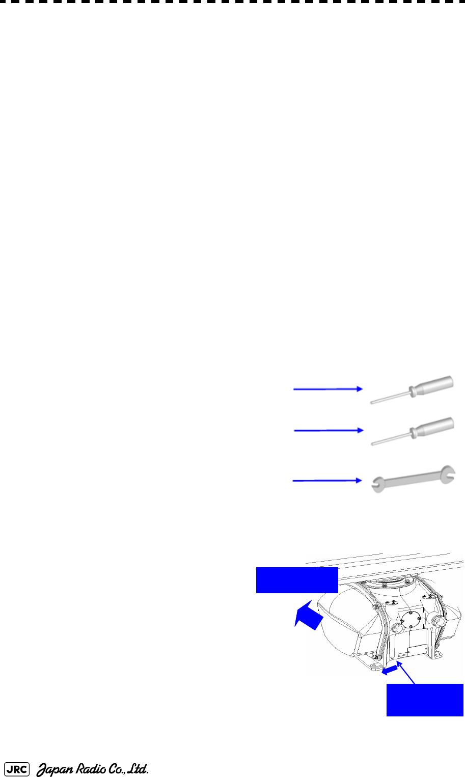
8-16
JMA-9100 Instruction Manual > 8.COUNTERMEASURE FOR TROUBLE ... > 8.4 REPLACEMENT OF MAJOR PARTS
1)
Turn on the power supply for the radar. Allow sufficient time for the radar to be
preheated (about 20 to 30 minutes / bring the radar unit to STBY mode).
2)
Start emitting radio waves from the short pulse range and gradually change the
emissions to the long pulse range. Open the service engineer menu to perform tuning
adjustment.
If operation becomes unstable, bring the radar unit back to STBY mode and restart
emission after allowing for an interval of 5 to 10 minutes.
3)
Emit radio waves in long pulse range mode for about 15 minutes and reopen the
service engineer menu to perform tuning adjustment.
Adjust the setting in the service engineer menu until the tuning indication bar on the
display unit reaches the 8th calibration marking.
Check in the service engineer menu that the magnetron current is between the 6th
and 9th calibration markings.
4)
Finally, initialize the transmission time in the service engineer menu.
8.4.2.2 Scanner Unit NKE-2254, NKE-1125
[Required tools]
•
A Phillips screwdriver for 4 mm screw
•
A Phillips screwdriver for 6 mm screw
•
A wrench (width across flats 13 mm, for M8 screws)
[Replacement procedure]
1)
Before starting part replacement work,
turn off the safety switch of the scanner
unit.
Bow direction
Turn off the
safety switch.
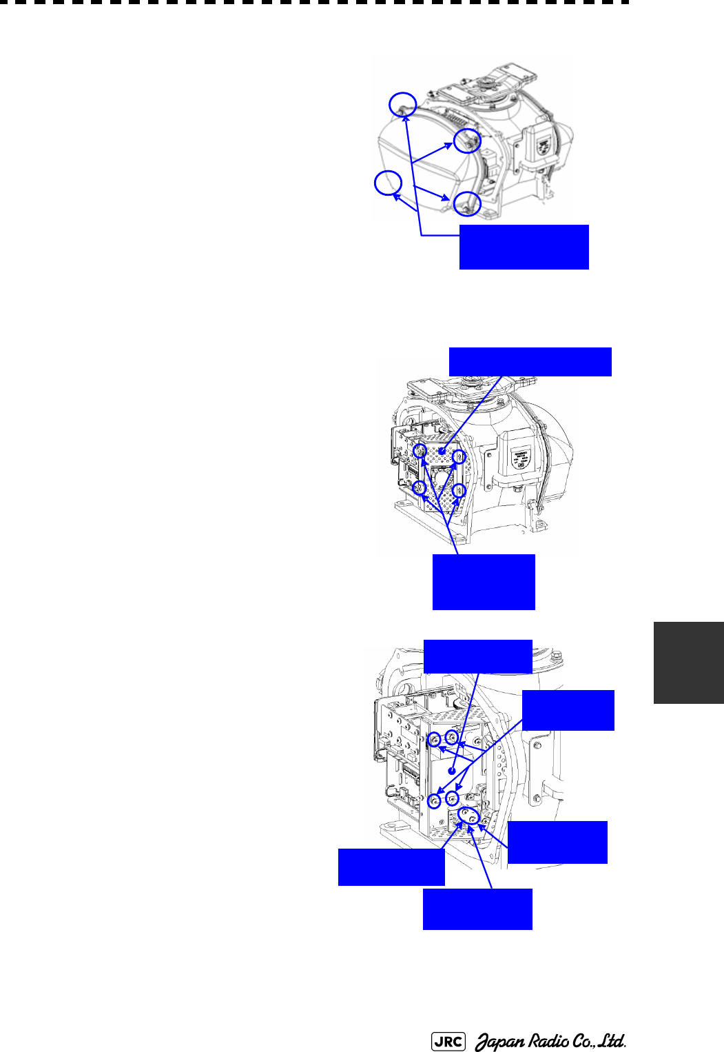
JMA-9100 Instruction Manual > 8.COUNTERMEASURE FOR TROUBLE ... > 8.4 REPLACEMENT OF MAJOR PARTS
8-17
8
2)
Loosen the hexagonal bolts (4) and
remove the pedestal cover.
Make sure that there is no foreign
matter or dust adhered to the gasket
when you put the cover on.
3)
Loosen the screws (four M4 screws) to
remove the magnetron cover.
4)
Make sure there is no charge remaining
in the modulation high-voltage circuit
board, and then remove the screws
(two M4 screws) holding the magnetron
cables (yellow and green) in place.
5)
Remove the screws (four M4 screws)
holding the magnetron in place, then
replace the magnetron after cutting the
leads (yellow and green) for the
replacement magnetron to an
appropriate length.
When the starboard side cover is removed
(4
Loosen the four
hexagonal bolts.
Loosen the
four screws.
Magnetron cover
Remove the
green cable.
Remove the
yellow cable.
Magnetron
Remove the
four screws.
Remove the
two screws.

8-18
JMA-9100 Instruction Manual > 8.COUNTERMEASURE FOR TROUBLE ... > 8.4 REPLACEMENT OF MAJOR PARTS
Use a non-magnetic screwdriver. If the magnetron comes into contact with any metal
(tool), its performance may deteriorate.
6)
After having replaced the magnetron, reassemble the unit by following the
disassembly procedure in the reverse order.
Do not forget to tighten the bolts and screws, and do not forget to reconnect the
cables.
Extreme care should be taken to connect the leads (yellow and green) to the magnetron
for prevention of contact with other parts or the casing. Contact may cause them to
discharge.
[Operation check]
After you have completed the replacement work, follow the procedure below to
check the operation.
1)
Turn on the power supply for the radar. Allow sufficient time for the radar to be
preheated (about 20 to 30 minutes / bring the radar unit to STBY mode).
2)
Start emitting radio waves from the short pulse range and gradually change the
emissions to the long pulse range. Open the service engineer menu to perform tuning
adjustment.
If operation becomes unstable, bring the radar unit back to STBY mode and restart
emission after allowing for an interval of 5 to 10 minutes.
3)
Emit radio waves in long pulse range mode for about 15 minutes and reopen the
service engineer menu to perform tuning adjustment.
Adjust the setting in the service engineer menu until the tuning indication bar on the
display unit reaches the 8th calibration marking.
Check in the service engineer menu that the magnetron current is between the 6th
and 9th calibration markings.
4)
Finally, initialize the transmission time in the service engineer menu.
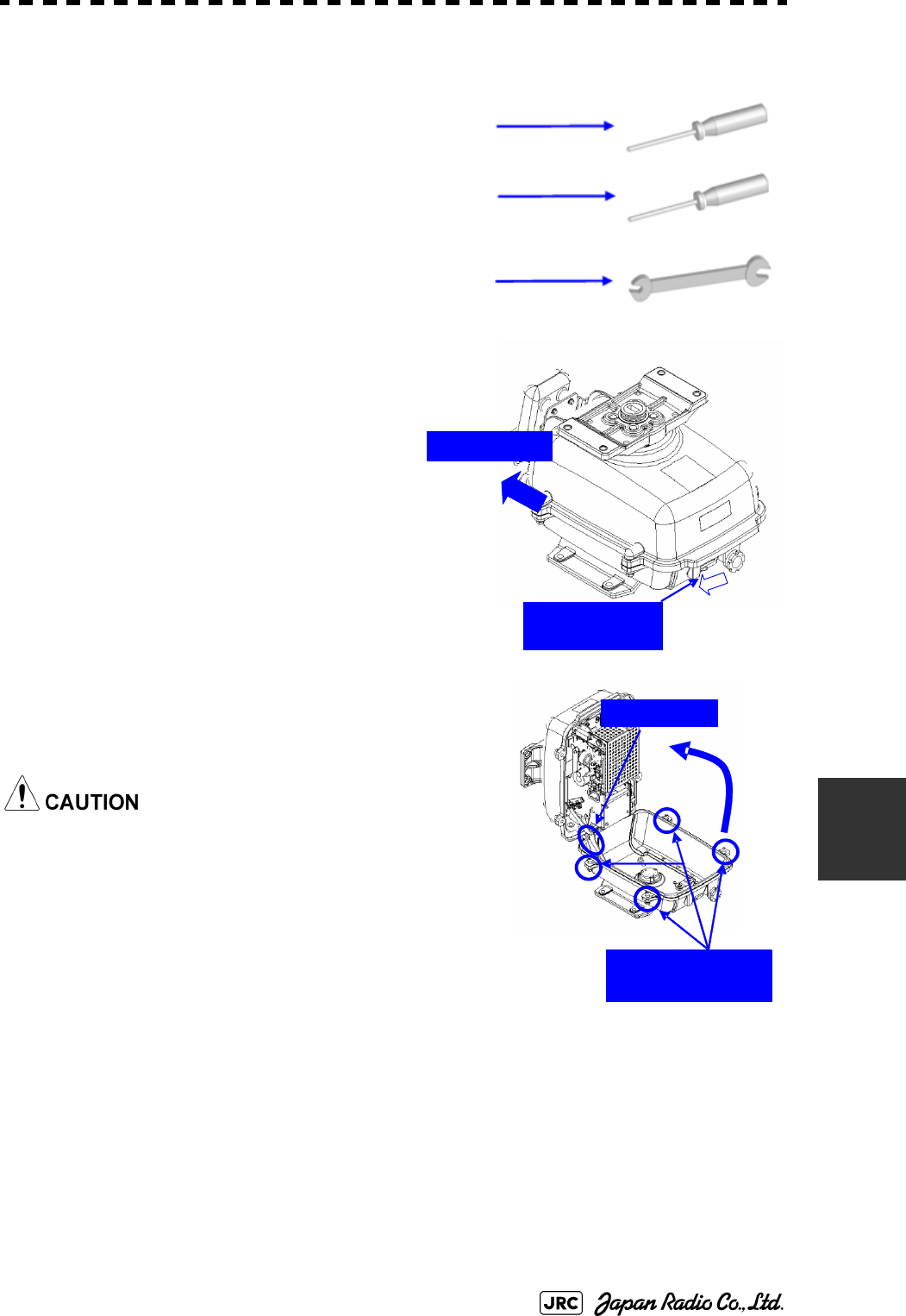
JMA-9100 Instruction Manual > 8.COUNTERMEASURE FOR TROUBLE ... > 8.4 REPLACEMENT OF MAJOR PARTS
8-19
8
8.4.2.3 Scanner Unit NKE-2103
[Required tools]
•
A Phillips screwdriver for 4 mm screw
•
A Phillips screwdriver for 6 mm screw
•
A wrench (width across flats 13 mm, for M8 screws)
1)
Before starting part replacement work,
turn off the safety switch on the bottom
of the scanner unit.
2)
Loosen the hexagonal bolts (four bolts)
and open the upper cover until the stopper of the
stay operates.
When closing the upper cover, release the stay
stopper and then tighten the cover.
Bow direction
Turn off the
safety switch.
Loosen the four
hexagonal bolts.
Stay
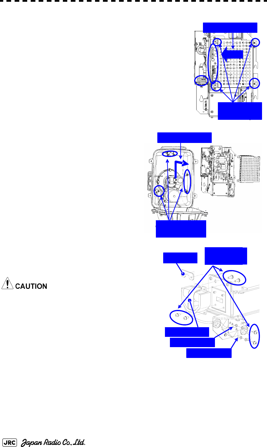
8-20
JMA-9100 Instruction Manual > 8.COUNTERMEASURE FOR TROUBLE ... > 8.4 REPLACEMENT OF MAJOR PARTS
1)
Loosen the screws (four M4 screws), remove the
transmitter-receiver unit cover, and remove the cables
connected to the transmitter-receiver unit (ten cables).
Slide the cover of the transmitter-receiver unit to
remove it.
2)
Loosen the bolts (five M5 bolts) and
remove the transmitter-receiver unit.
Slide the transmitter-receiver unit
upward to remove it.
3)
Remove the screws (six M4 screws)
holding the magnetron in place and replace
the magnetron.
Use a non-magnetic screwdriver. If the
magnetron comes into contact with any metal
(tool), its performance may deteriorate.
4)
Cut the leads (yellow and green) for the
replacement magnetron to an appropriate
length, then tighten the screws and fix the
cables in place.
After having replaced the magnetron, reassemble the unit by following the
disassembly procedure in the reverse order.
Loosen the
four screws.
Slide the cover.
Tighten the
five bolts.
Slide the unit.
Magnetron
Nut plate Remove the
six screws.
Yellow cable
Green cable

JMA-9100 Instruction Manual > 8.COUNTERMEASURE FOR TROUBLE ... > 8.4 REPLACEMENT OF MAJOR PARTS
8-21
8
Do not forget to tighten the bolts and screws, and do not forget to reconnect the cables.
Extreme care should be taken to connect the leads (yellow and green) to the magnetron
for prevention of contact with other parts or the casing.
[Operation check]
After you have completed the replacement work, follow the procedure below to
check the operation.
1)
Turn on the power supply for the radar. Allow sufficient time for the radar to be
preheated (about 20 to 30 minutes / bring the radar unit to STBY mode).
2)
Start emitting radio waves from the short pulse range and gradually change the
emissions to the long pulse range. Open the service engineer menu to perform tuning
adjustment.
If operation becomes unstable, bring the radar unit back to STBY mode and restart
emission after allowing for an interval of 5 to 10 minutes.
3)
Emit radio waves in long pulse range mode for about 15 minutes and reopen the
service engineer menu to perform tuning adjustment.
Adjust the setting in the service engineer menu until the tuning indication bar on the
display unit reaches the 8th calibration marking.
Check in the service engineer menu that the magnetron current is between the 4th
and 6th calibration markings.
4)
Finally, initialize the transmission time in the service engineer menu.
8.4.2.4 Transmitter Receiver Unit NTG-3230
[Required tools]
A flatblade screwdriver for 6 mm screws
•
A Phillips screwdriver for 4 mm screw
•
A Phillips screwdriver for 6 mm screw
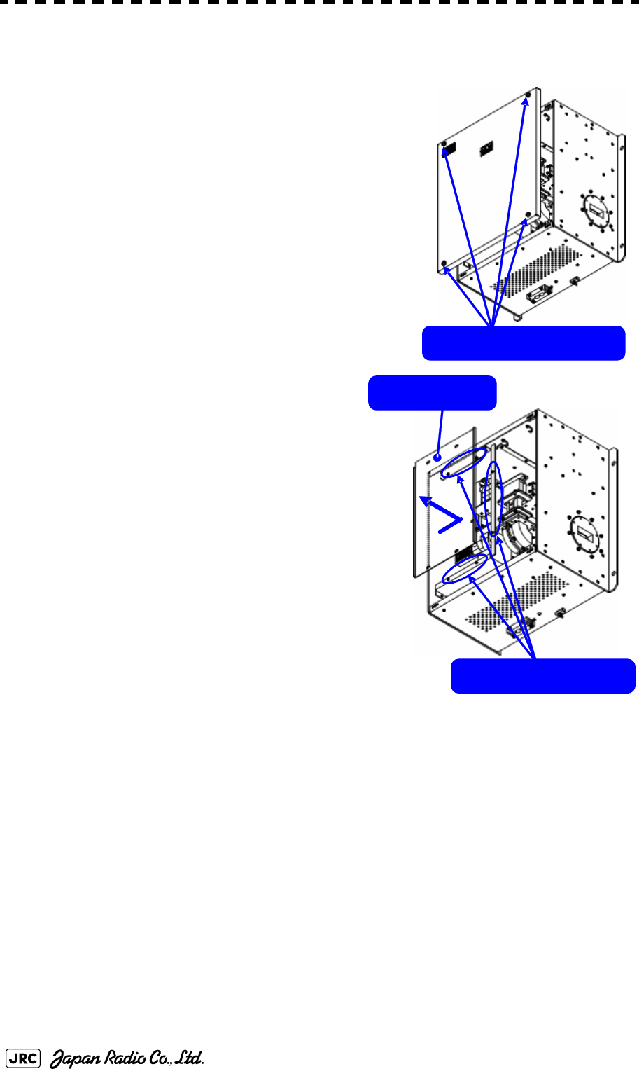
8-22
JMA-9100 Instruction Manual > 8.COUNTERMEASURE FOR TROUBLE ... > 8.4 REPLACEMENT OF MAJOR PARTS
[Replacement procedure]
1)
Loosen the four screws and remove the cover.
The screws are slotted captive screws.Use a
flatblade screwdriver.
2)
Remove the screws (six M4 screws) and slide
the modulator cover to the right to remove
it.
Remove the four screws.
Loosen the six screws.
Modulator cover
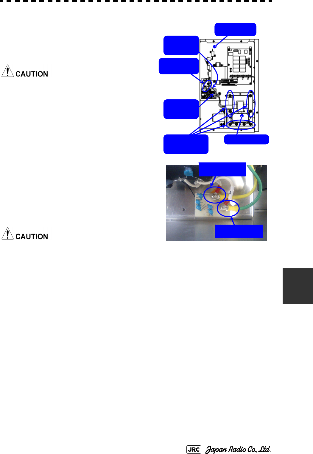
JMA-9100 Instruction Manual > 8.COUNTERMEASURE FOR TROUBLE ... > 8.4 REPLACEMENT OF MAJOR PARTS
8-23
8
3)
Remove the screws holding the cables (two
M4 screws) and the bolts holding the
magnetron (eight M6 screws) and remove the
metal fitting and the magnetron.
Use a non-magnetic screwdriver. If the
magnetron comes into contact with any metal
(tool), its performance may deteriorate.
4)
Be careful to attach the colored cables
(yellow and green) to the correct connections
on the replacement magnetron.
After having replaced the magnetron,
reassemble the unit by following the
disassembly procedure in the reverse order.
Do not forget to tighten the bolts and screws, and
do not forget to reconnect the cables.
[Operation check]
After you have completed the replacement work, follow the procedure below to
check the operation.
1)
Turn on the power supply for the radar. Allow sufficient time for the radar to be
preheated (about 20 to 30 minutes / bring the radar unit to STBY mode).
2)
Start emitting radio waves from the short pulse range and gradually change the
emissions to the long pulse range. Open the service engineer menu to perform tuning
adjustment.
If operation becomes unstable, bring the radar unit back to STBY mode and restart
emission after allowing for an interval of 5 to 10 minutes.
3)
Emit radio waves in long pulse range mode for about 15 minutes and reopen the
service engineer menu to perform tuning adjustment.
Yellow
cable
Magnetron
Modulator
Green
cable
Remove the
eight bolts.
Remove the
two screws.
Green cable
Yellow cable
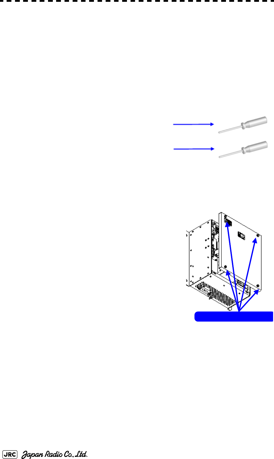
8-24
JMA-9100 Instruction Manual > 8.COUNTERMEASURE FOR TROUBLE ... > 8.4 REPLACEMENT OF MAJOR PARTS
Adjust the setting in the service engineer menu until the tuning indication bar on the
display unit reaches the 8th calibration marking.
Check in the service engineer menu that the magnetron current is between the 6th
and 9th calibration markings.
4)
Finally, initialize the transmission time in the service engineer menu.
8.4.2.5 Transmitter Receiver Unit NTG-3225
[Required tools]
A flatblade screwdriver for 6 mm screws
・A Phillips screwdriver for 4 mm screw
[Replacement procedure]
1)
Loosen the four screws and remove the cover.
The screws are slotted captive screws.Use a flatblade
screwdriver.
Loosen the four screws .
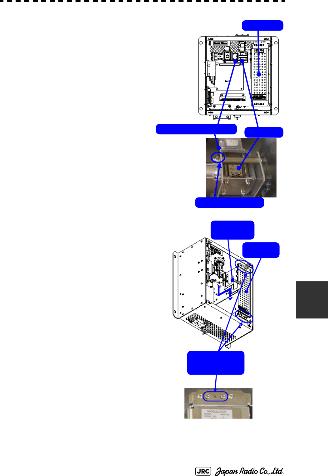
JMA-9100 Instruction Manual > 8.COUNTERMEASURE FOR TROUBLE ... > 8.4 REPLACEMENT OF MAJOR PARTS
8-25
8
2)
Loosen the upset head bolt (one M4 bolt),
and slide the tightening metal fitting,
located between the modulator and the
circulator, to remove it.
The magnetron is installed within the
modulator.
3)
Loosen the inside screws of the modulator
(four M4 screws).
Removing the outside screws makes it
possible to slide the modulator.
Tightening metal fitting Circulator
Modulator
Remove the screw.
Loosen the four
screws.
Tightening
metal fitting
Modulator
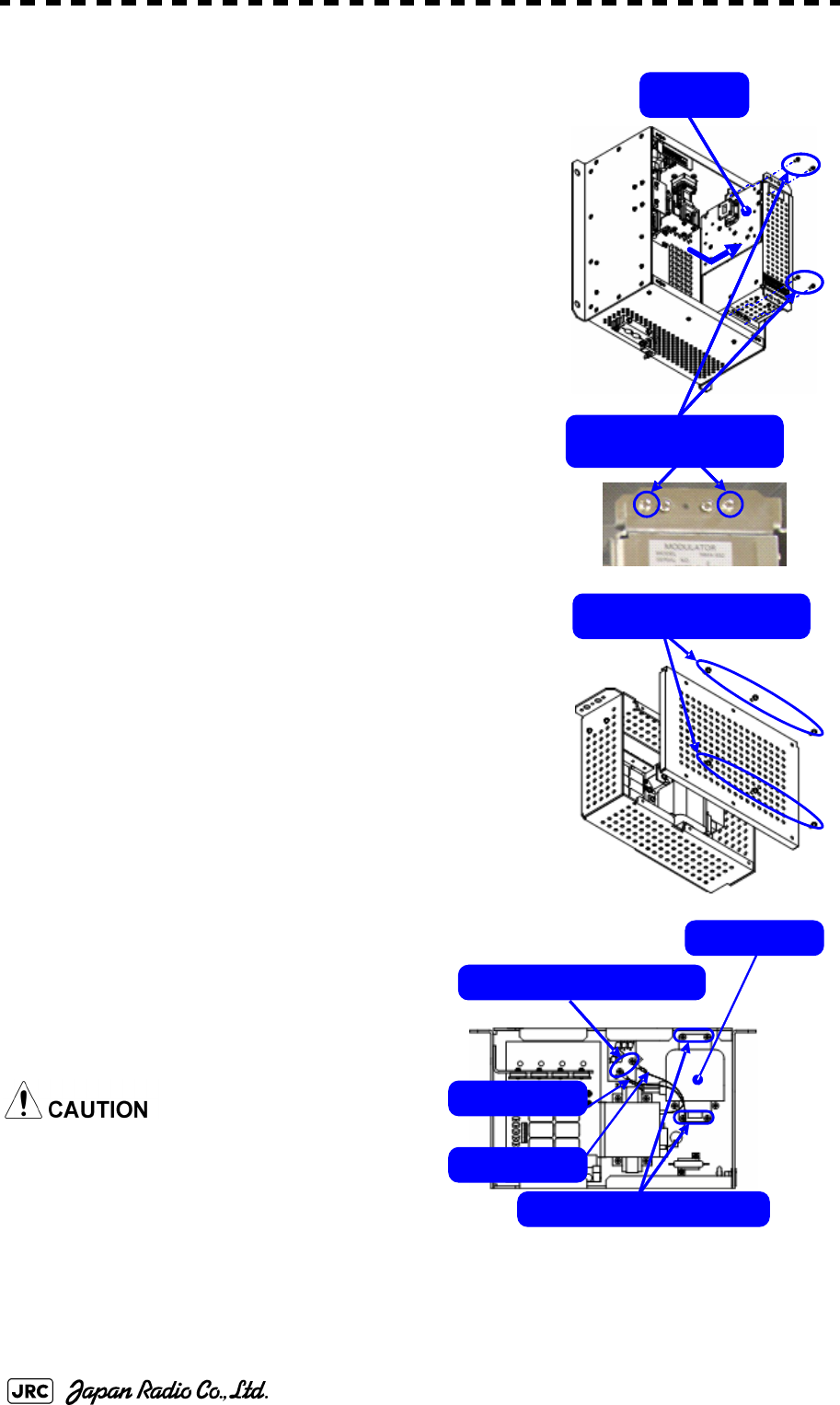
8-26
JMA-9100 Instruction Manual > 8.COUNTERMEASURE FOR TROUBLE ... > 8.4 REPLACEMENT OF MAJOR PARTS
4)
Remove the cables connected to the modulator and
the screws on the outside of the modulator (four M4
screws) and slide the modulator to the right to
remove it.
5)
Remove the screws (six M4 screws) and take off the
modulator cover.
6)
Remove the screws holding the cables
(two M4 screws) and the screws holding
the magnetron (four M4 screws) and
remove the metal fitting and the
magnetron.
Use a non-magnetic screwdriver. If the
magnetron comes into contact with any
metal (tool), its performance may
deteriorate.
Remove the four
outside screws.
Modulator
Remove the six screws.
Remove the four screws.
Magnetron
Remove the two screws.
Green cable
Yellow cable
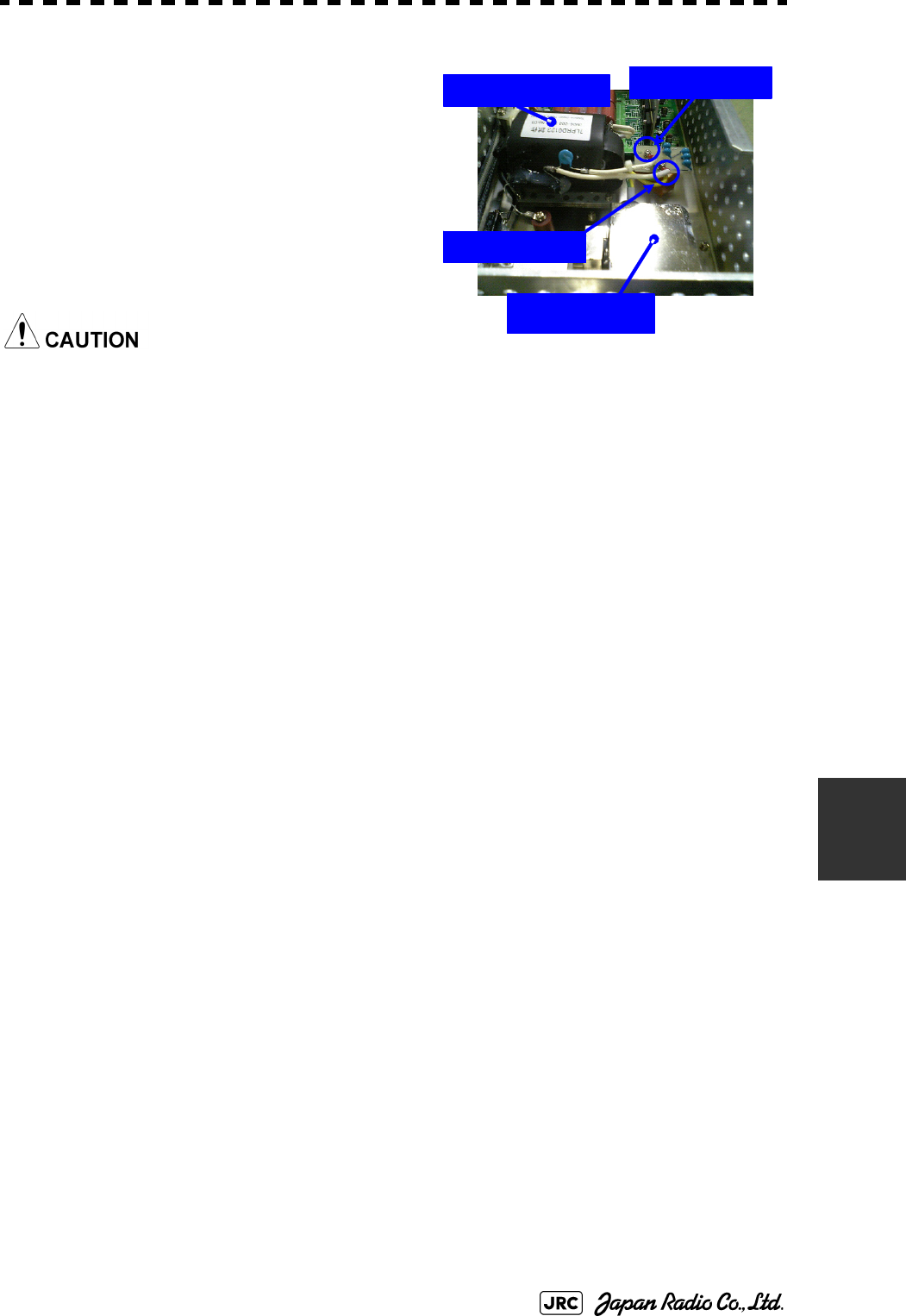
JMA-9100 Instruction Manual > 8.COUNTERMEASURE FOR TROUBLE ... > 8.4 REPLACEMENT OF MAJOR PARTS
8-27
8
7)
Be careful to attach the colored cables
(yellow and green) to the correct
connections on the replacement
magnetron.
After having replaced the magnetron,
reassemble the unit by following the
disassembly procedure in the reverse
order.
Do not forget to tighten the bolts and screws,
and do not forget to reconnect the cables.
[Operation check]
After you have completed the replacement work, follow the procedure below to
check the operation.
1)
Turn on the power supply for the radar. Allow sufficient time for the radar to be
preheated (about 20 to 30 minutes / bring the radar unit to STBY mode).
2)
Start emitting radio waves from the short pulse range and gradually change the
emissions to the long pulse range. Open the service engineer menu to perform tuning
adjustment.
If operation becomes unstable, bring the radar unit back to STBY mode and restart
emission after allowing for an interval of 5 to 10 minutes.
3)
Emit radio waves in long pulse range mode for about 15 minutes and reopen the
service engineer menu to perform tuning adjustment.
Adjust the setting in the service engineer menu until the tuning indication bar on the
display unit reaches the 8th calibration marking.
Check in the service engineer menu that the magnetron current is between the 6th
and 9th calibration markings.
4)
Finally, initialize the transmission time in the service engineer menu.
Magnetron
Pulse transformer
Yellow cable
Green cable
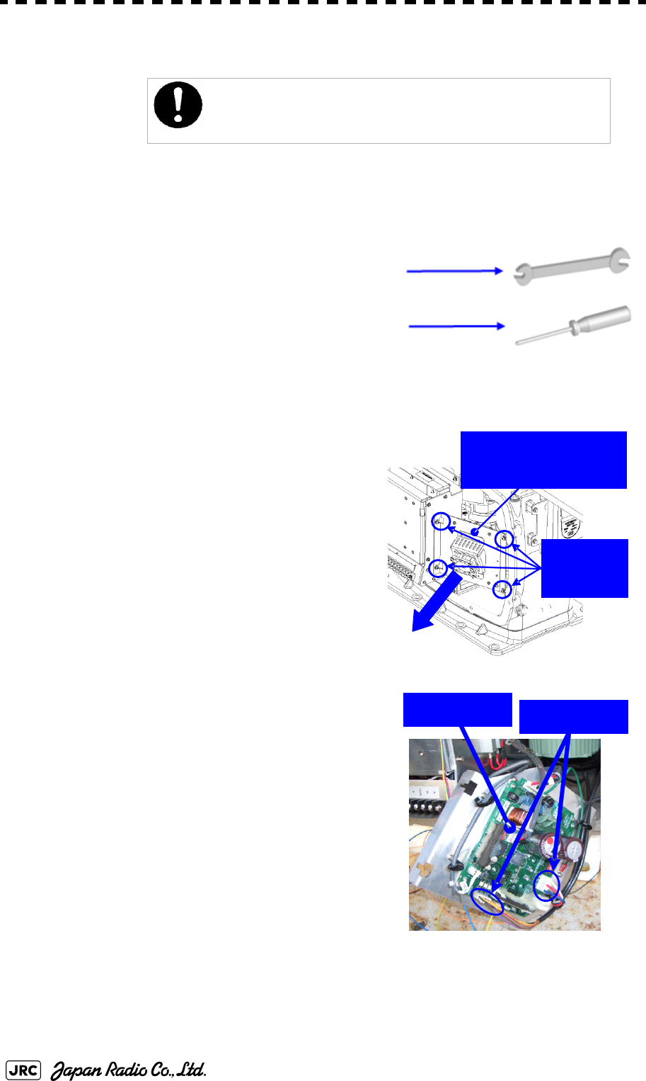
8-28
JMA-9100 Instruction Manual > 8.COUNTERMEASURE FOR TROUBLE ... > 8.4 REPLACEMENT OF MAJOR PARTS
8.4.3 Replacement of Motor
8.4.3.1 Scanner Unit NKE-1139/1130
[Required tools]
•
A wrench (width across flats 17 mm, for M10 screws)
•
A Phillips screwdriver for 4 mm screw
•
Tools for removing the cover from the scanner unit.(Refer
to the 8.4.2.1)
[Replacement procedure]
1)
Remove the cover on the right (starboard)
side (see
8.4.2.1
) and loosen the four screws
(M4) to remove the driver unit, which has
the motor driver circuit board on its back
side.
Disconnect the cables connecting the motor
to the motor driver circuit board.
Replacement of motor must be made by specialized service
personnel.
For details, refer to Service Manual.
Driver unit (driver circuit
board at the back side)
Remove the
four screws.
Driver circuit
board Disconnect the
cables.
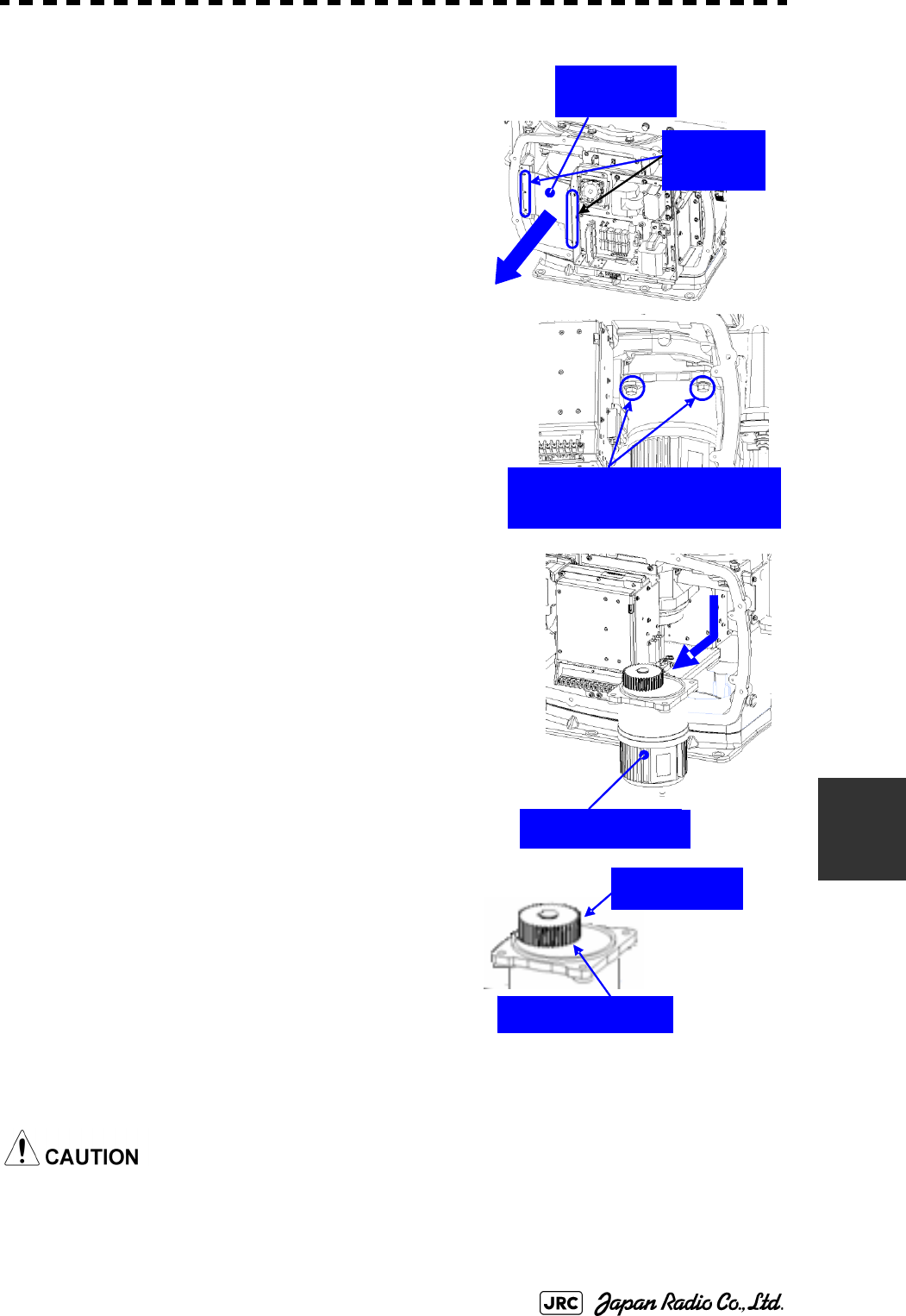
JMA-9100 Instruction Manual > 8.COUNTERMEASURE FOR TROUBLE ... > 8.4 REPLACEMENT OF MAJOR PARTS
8-29
8
2)
Remove the cover on the left (port) side and
remove the five screws (M5) to remove the
fixture.
3)
Remove the four hexagonal screws (M10x40,
SW10, and W10) that hold the motor from both the
right and left sides to remove the motor.
4)
Apply grease to the gear wheel of the new
motor.
5)
Install the new motor in the scanner unit and
secure it using the hexagonal screws. Tighten
the screws with the specified torque (380 kgf-
cm).
6)
After replacing the motor, assemble the unit
in the reverse order of the disassembly procedure.
Do not forget to tighten the screws and connect the cables.
Remove the
metal fixture.
Remove the
five screws.
Remove the four hexagonal
screws (two screws on each side)
Remove the motor.
Apply grease.
Motor gear wheel
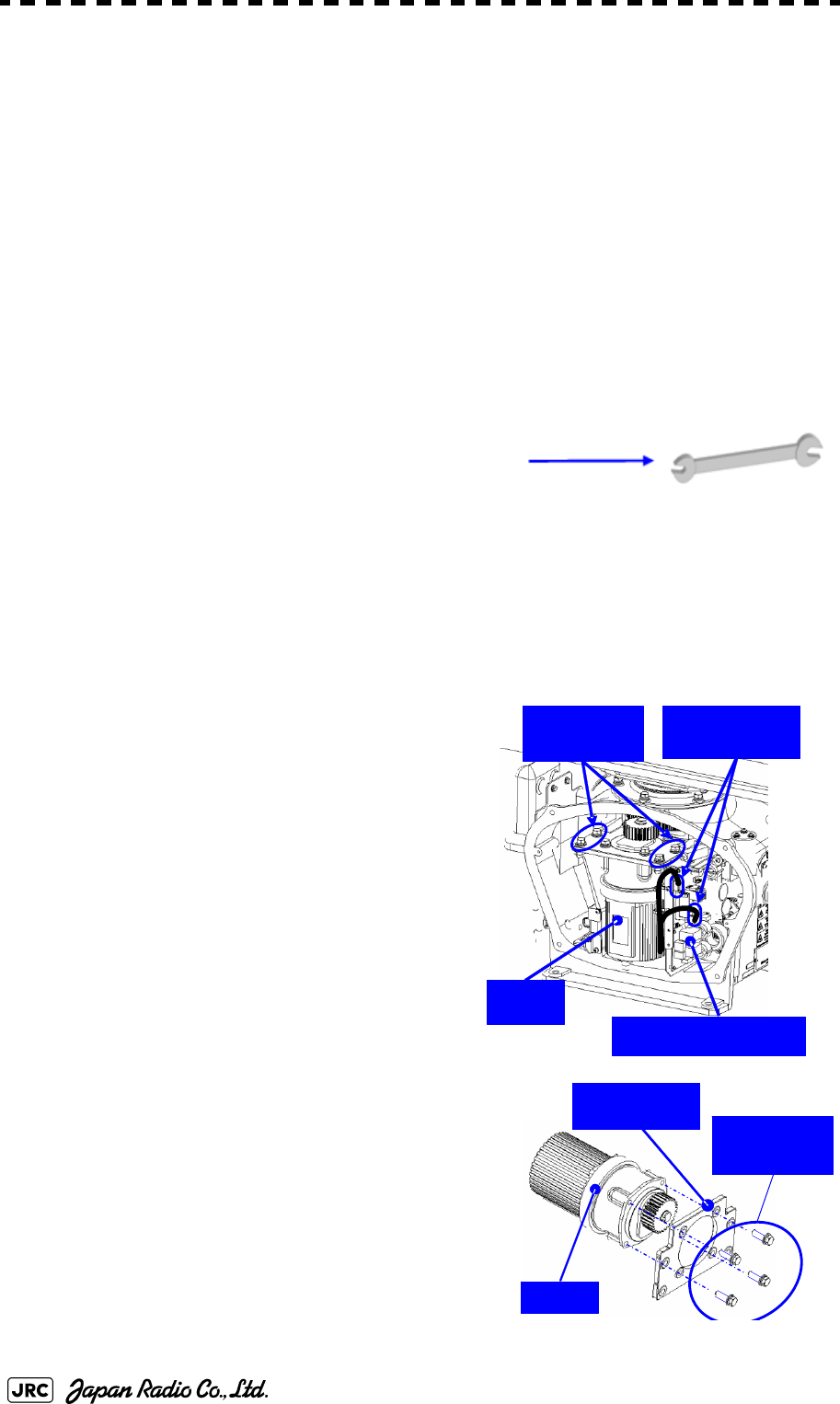
8-30
JMA-9100 Instruction Manual > 8.COUNTERMEASURE FOR TROUBLE ... > 8.4 REPLACEMENT OF MAJOR PARTS
[Operation check]
After you have completed the replacement work, follow the procedure below to
check the operation.
1)
Turn on the radar power supply. After the countdown is completed, start emission
and check that the radar image appears without error. Check that you do not hear
any unusual sound when the motor starts, rotates, and stops.
2)
Open the service engineer menu to initialize the motor rotation time.
8.4.3.2 Scanner Unit NKE-1125/2254
[Required tools]
•
Single-ended wrench (width across flats 17 mm for M8
bolts)
•
Tools for removing the cover from the scanner unit.(Refer to the 8.4.2.2)
[Replacement procedure]
1)
Remove the cover on the left (port) side
(see Section 8.4.2.2) and remove the
cables connected to the motor driver
circuit board.
2)
Remove the hexagonal bolts (four M8
bolts) and remove the motor.
3)
Remove the hexagonal bolts (four M8
bolts) and remove the installation plate from the
motor.
Motor
Motor driver circuit
Remove the
four bolts.
Remove the
two cables.
Motor
Motor driver
circuit board
Remove the
four bolts.
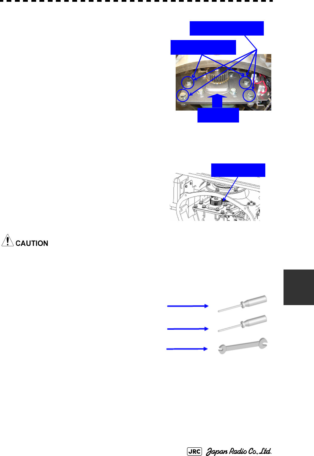
JMA-9100 Instruction Manual > 8.COUNTERMEASURE FOR TROUBLE ... > 8.4 REPLACEMENT OF MAJOR PARTS
8-31
8
4)
Attach the installation plate to the replacement
motor. Do not forget to tighten the hexagonal
bolts to an appropriate torque (210 kgf-cm) so
they are free of looseness.
5)
Install the motor into the scanner unit. Press the
motor against the protrusions of the arm fixed to
the motor on which the arm extends through the
wall of the casing, adjust it to minimize backlash,
and fix it in place.
Do not forget to tighten the hexagonal bolts, to an appropriate torque (140 kgf-cm)
so they are free of looseness.
6)
After having installed the motor, grease the
gear wheel.
7)
After having replaced the motor, reassemble
the unit by following the disassembly
procedure in the reverse order.
Do not forget to tighten the bolts and screws, and do not forget to reconnect the cables.
8)
8.4.3.3 Scanner Unit NKE-2103
[Required tools]
•
A Phillips screwdriver for 4 mm screw
•
A Phillips screwdriver for 5 mm screw
•
Single-ended wrench (width across flats 10 mm for M6
bolts)
•
Tools for removing the cover from the scanner
unit.(Refer to the
8.4.2.3
)
Arm protrusions
Press
Tighten the four bolts.
Grease here.
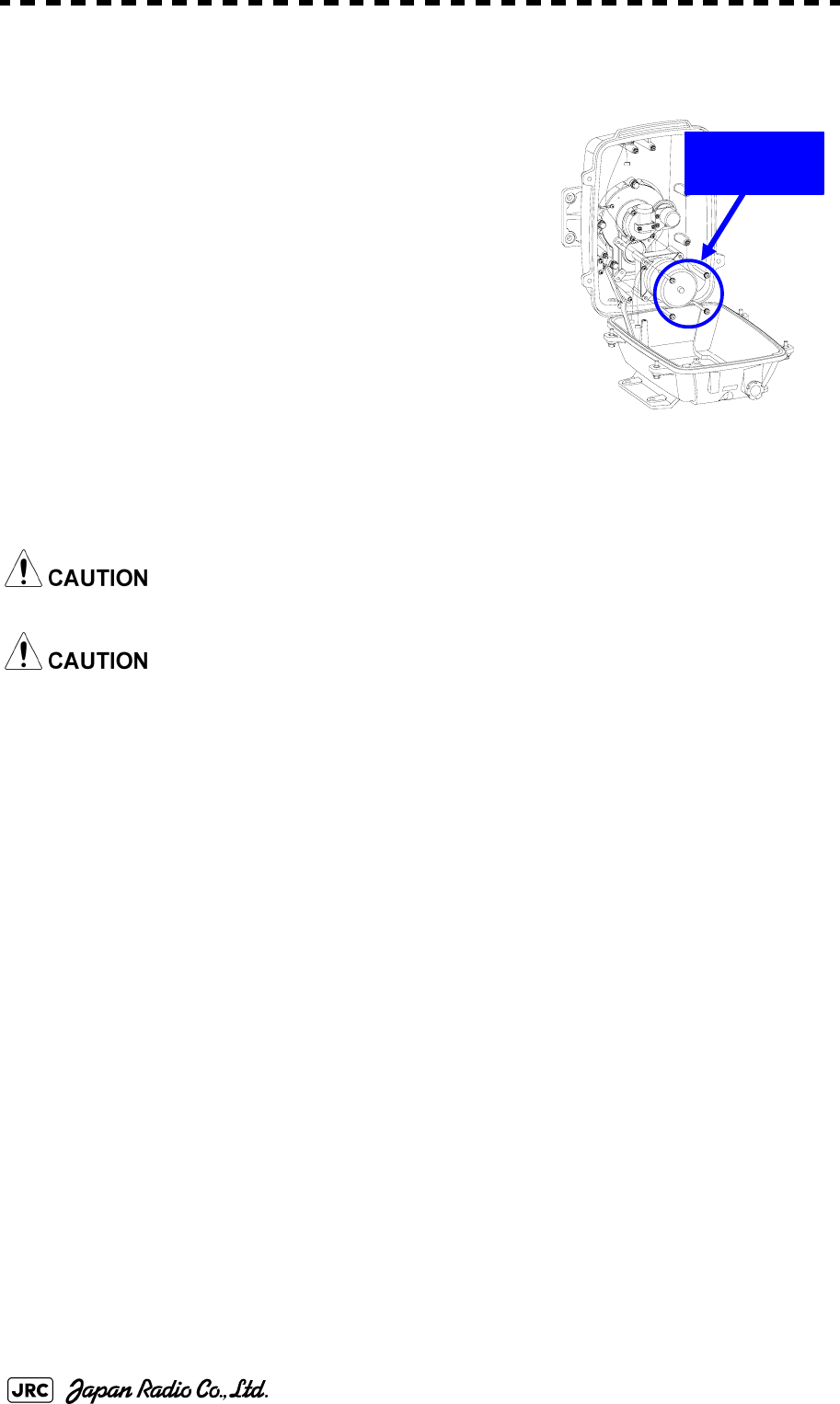
8-32
JMA-9100 Instruction Manual > 8.COUNTERMEASURE FOR TROUBLE ... > 8.4 REPLACEMENT OF MAJOR PARTS
[Replacement procedure]
1)
Open the upper cover (see Section 8.4.2.3) to
remove the transmitter-receiver unit.
2)
Remove the hexagonal bolts (four M6 bolts) and
remove the motor. Grease the gear wheel of the
replacement motor and place it in the casing. Do
not forget to tighten the hexagonal bolts to an
appropriate torque (72 kgf-cm) so they are free of
looseness.
3)
After having replaced the motor, reassemble the unit by following the disassembly
procedure in the reverse order.
Do not forget to tighten the bolts and screws, and do not forget to reconnect the cables.
Clamp the cables so they do not interfere with the rotation of the motor's rotors.
[Operation check]
After you have completed the replacement work, follow the procedure below to
check the operation.
1)
Turn on the radar and emit radar waves once the countdown is finished, and check
that the radar image is correctly displayed. Check that the motor does not make any
abnormal sound when it starts to rotate, while it is rotating, or when it stops.
Remove the
four bolts.