Japan Radio Co NKE2044 MARINE RADAR User Manual 3
Japan Radio Co Ltd. MARINE RADAR 3
Contents
- 1. User Manual 1
- 2. User Manual 2
- 3. User Manual 3
- 4. User Manual 4
- 5. User Manual 5
User Manual 3
Chapter 4 MEASURE THE SURROUND SHIP
60
Chapter 4 MEASURE THE SURROUND SHIPS
4-1 MEASURE DIRECTION AND RANGE USING VRM/EBL
4-1-1 ICON DISPLAY
VRM(Variable Range Marker) (ST-BY) When activated functions.(TX)
EBL(Electric Bearing Line) (ST-BY) When activated functions.(TX)
4-1-2 OPERATION OF VRM, EBL ICON
* VRM Tap ring, and Flick: VRM ring size will moving, meet to the target to ring together.
That target Range is displayed on screen as VRM. .
Ob course, it is possible to use Rotary knob, turn and press.
Erase VRM: Select VRM icon by Rotary knob and double tap the icon,
or double push the Rotary knob.
*EBL Tap line, and Flick: EBL line direction will rotate, meet line to the target together.
The target Bearing is displayed on screen as EBL. .
Ob course, it is possible to use Rotary knob, turn and press.
Erase EBL: Select EBL icon by Rotary knob and double tap the icon,
or double push the Rotary knob.
Chapter
8
DETAIL PERFORMANCE SE
TTING
100
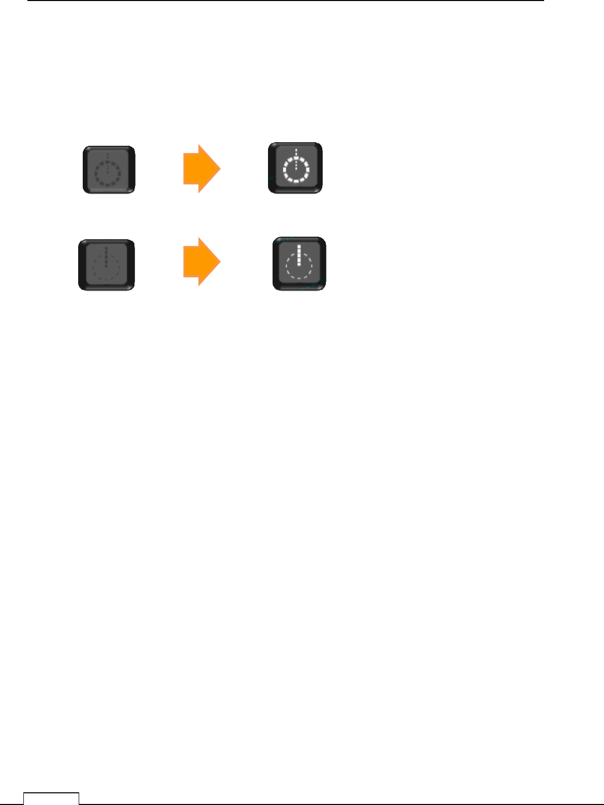
8-1-1 MAIN BANG SUPPRESSION
(Usually, doesn’t need set up. adjust if necessary)
This adjustment is decrease the transmitted signal which appears as a circular echo around the
center.
Adjustment is done so as to main bang is observe slightly seen.
Excess adjusting is danger for nearest small target observation.
If the main bang is not so big, use as factory setting.
Chapter 8 DETAIL RFORMANCE SETTING
101
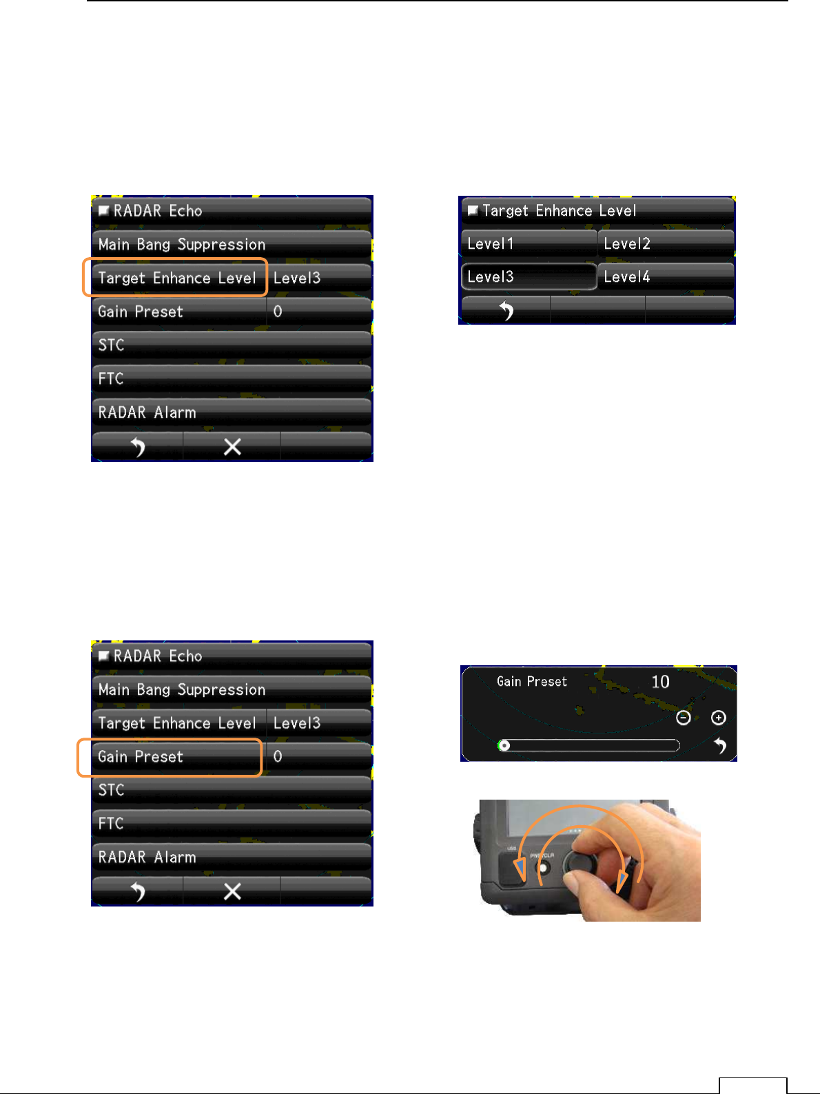
8-1-2 TARGET EXPANSION
Level setting.
The level which can be set up is level 1, the level 2, the level 3, and the level 4.
Expansion and the magnifying the observation target size..
Tap the “Level1, Level2, Level3, Level4“ icon.
8-1-3 GAIN LEVEL
(Important adjustment. Since adjusted in factory, adjustment is not necessary in the field.)
Chapter
8
DETAIL PERFORMANCE SE
TTING
102
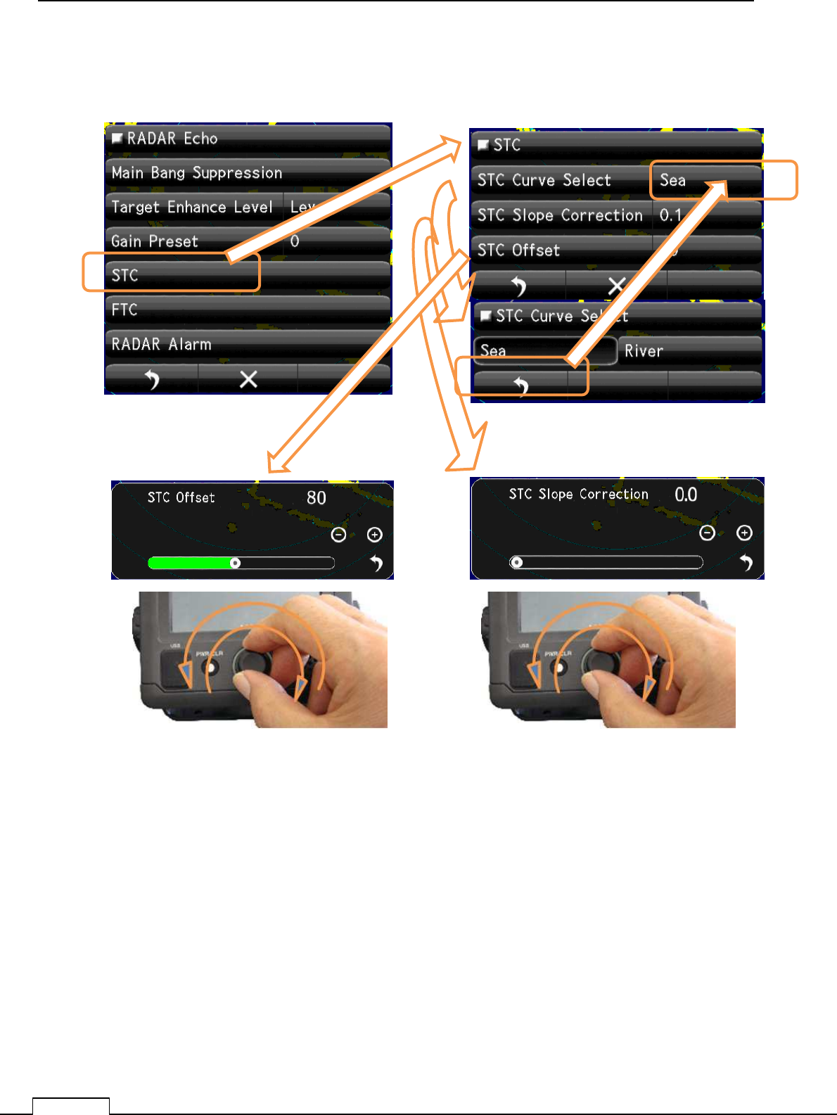
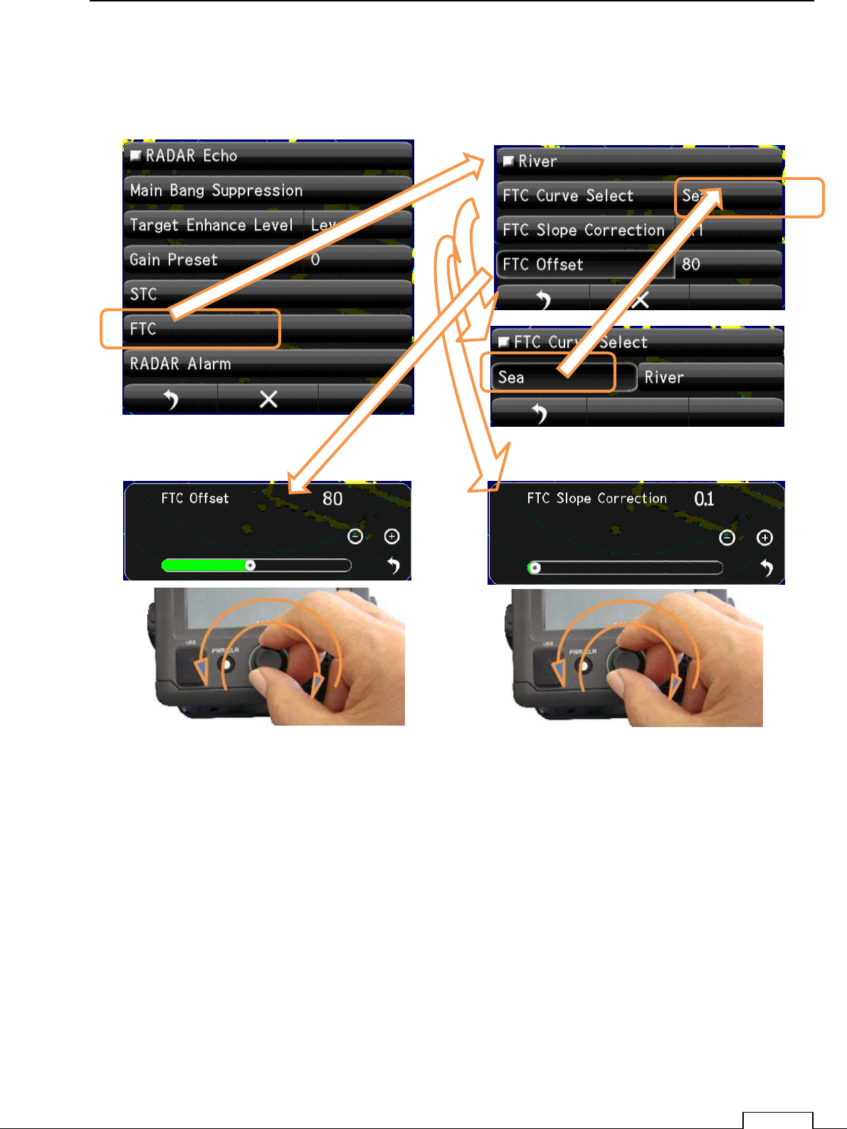
8-1-4 SEA CLUTTER LEVEL
(Important adjustment. Since adjusted in factory, adjustment is not necessary in the field.)
Chapter 8 DETAIL RFORMANCE SETTING
103
8-1-5 RAIN AND SNOW CLUTTER LEVEL
(Important adjustment. Since adjusted in factory, adjustment is not necessary in the field.)
Chapter
8
DETAIL PERFORMANCE SE
TTING
104
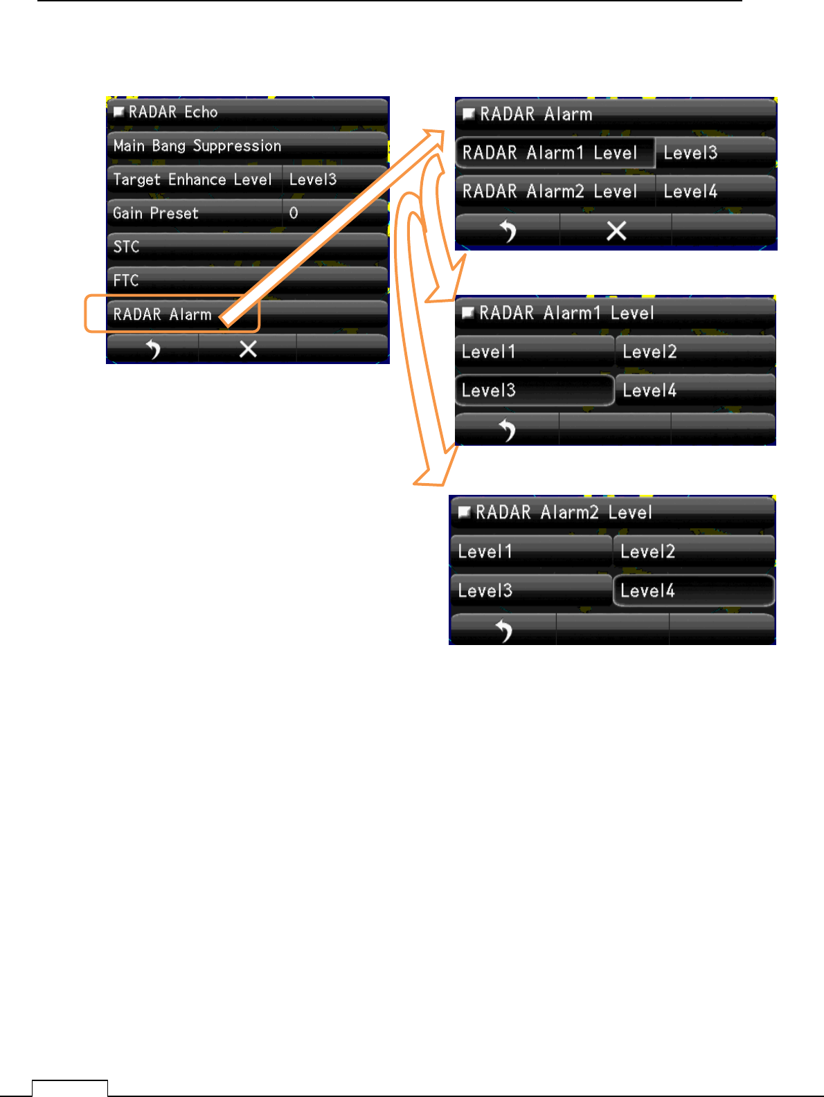
8-1-6 RADAR Alarm LEVEL
Set up Alarm 1 Level
Set up Alarm 2 Level
Chapter 8 DETAIL RFORMANCE SETTING
105
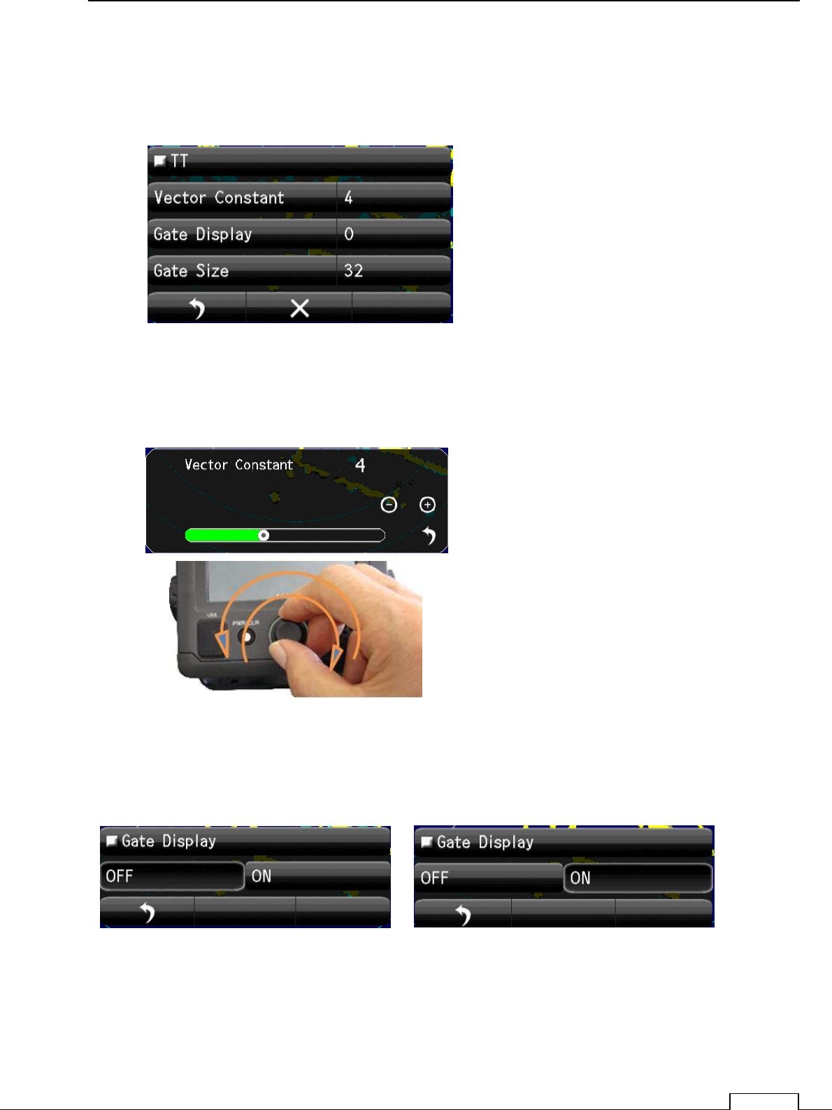
8-2 TT(TARGET TRACKING) FUNCTION
(Important adjustment. Since adjusted in factory, adjustment is not necessary in the field.)
Vector shows the movement of the target.
Vector Constant large. Vector is stable, but the response is slow.
Vector Constant small. Vector is unstable, but the response is quick..
Tap Vector Constant, setting Bar appears lower part of screen.
Set up by flick or tap + -.
Rotary knob adjusting is possible. Click and set.
Gate Display: The region automatically search target moving area.
ON: Confirmation is possible under green searching area.
OFF: Doesn’t display automatically searching area.
Chapter
8
DETAIL PERFORMANCE SE
TTING
106
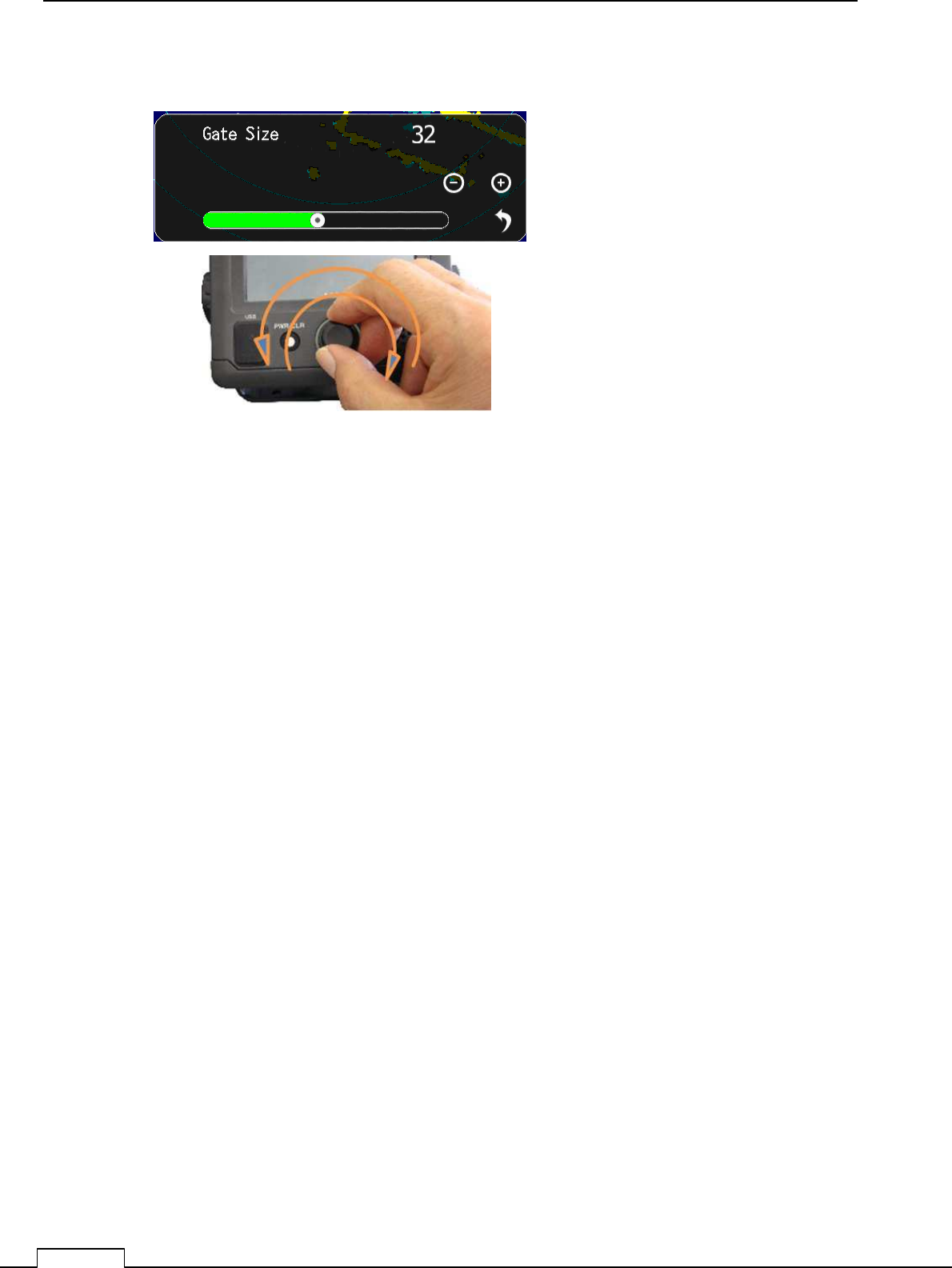
Gate Size: Set up the region size which can search the moving target automatically.
Wide region: Possible to track fast moving target, but many clutters are include.
Sometime do miss tracking because of much noise.
Narrow region Possible to track stable, but fast moving target are tend to lost.
Because of first target soon goes outside of the region.
Chapter 8 DETAIL RFORMANCE SETTING
107
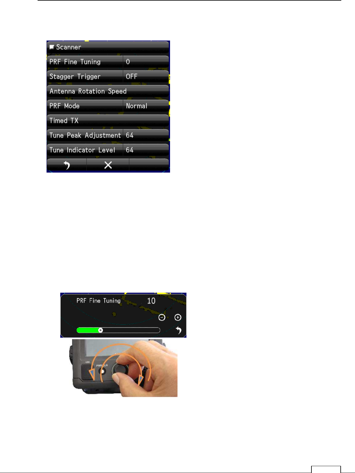
8-3 SCANNER FUNCTION
8-3-1 PULSE REPETITION FREQUENCY FINE TUNING (PRF ADJUST)
When existing the same frequency radar, in the same area, they interfere each other.
If p.r.f.(pulse reputation frequency)is the same, Interference can’t reject on the screen.
In that case shift the p.r.f. a little may decrease the radar interference.
PRF Fine Tuning:
If radar interference cannot reject completely, it is effective way to shift the PRF.
Watching the screen echo, rotate the
Rotary knob and stop when radar
interference are fade out from screen.
Chapter
8
DETAIL PERFORMANCE SE
TTING
108
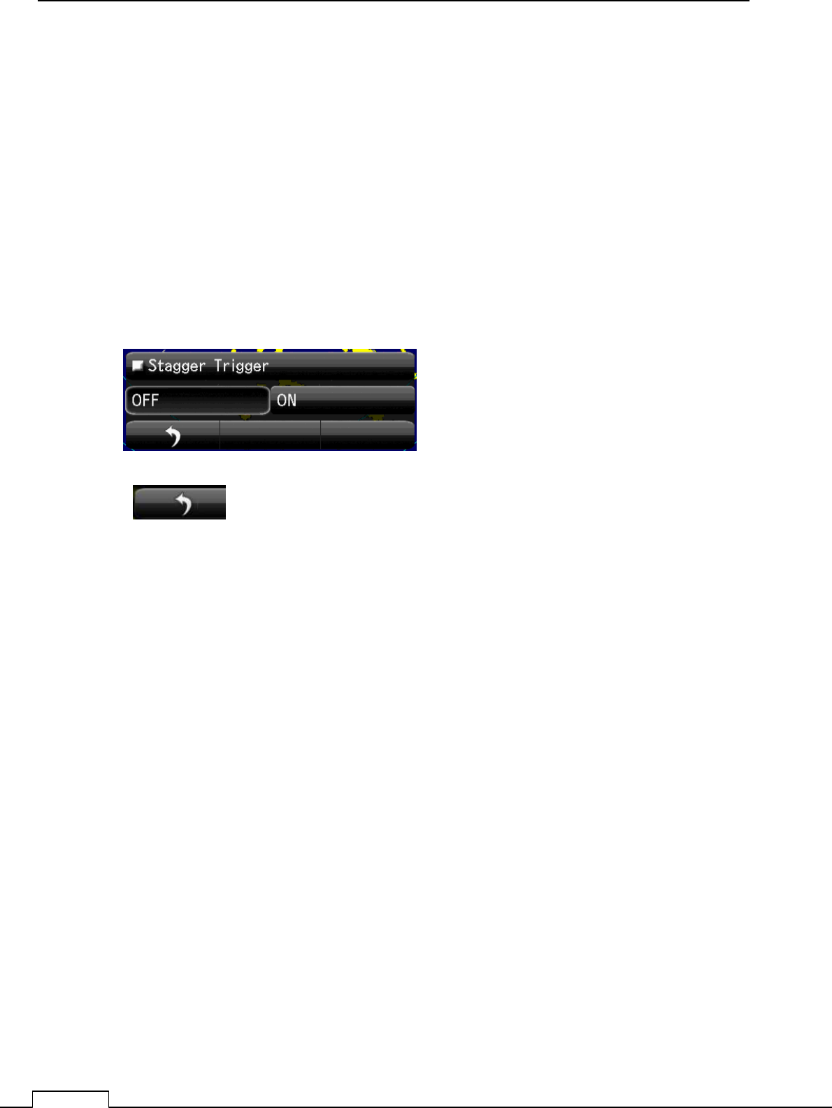
8-3-2 STAGGER TRIGGER
When existing the same frequency radar, in the same area, they interfere each other.
If p.r.f.(pulse reputation frequency)is the same, Interference can’t reject on the screen.
Another way to decease interference is shift the transmitting time randomly.
Not synchronize signal which transmit randomly is eliminate.
So decrease the other radar interference echo on screen.
ON Stagger: Stagger trigger is generated
OFF Stagger: Stagger trigger stop. (Normal trigger timing)
Select and Tap
.
Watching the screen echo, select off or on
when heavy radar interference on screen.
return to the menu
Chapter 8 DETAIL RFORMANCE SETTING
109
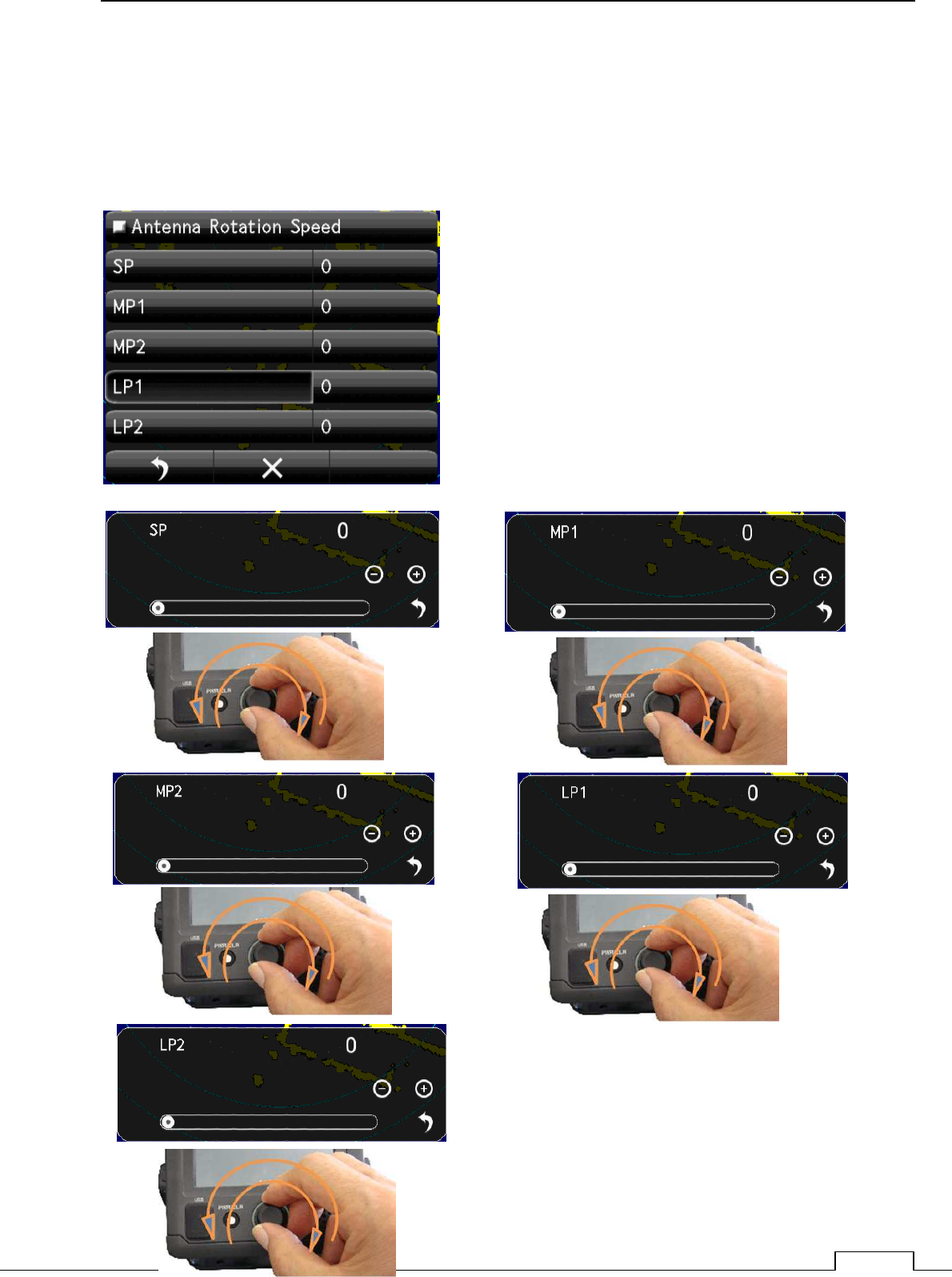
8-3-3 SCANNER ROTATIONAL SPEED
The rotational speed of inside microwave radiator is possible to change.
The sensitivity of radar are low speed is more higher.
So scanner rotation speed is possible to change according observing range.
Every pulse length can select the Antenna rotation speed.
Short range uses short pulse (SP).
Medium range uses medium pulse (MP)
Long range uses Long pulse (LP)
Shorter range requires the High speed refresh screen.
Longer range requires the Low speed for High sensitivity.
User can select rotational speed according to his request.
Chapter
8
DETAIL PERFORMANCE SE
TTING
110
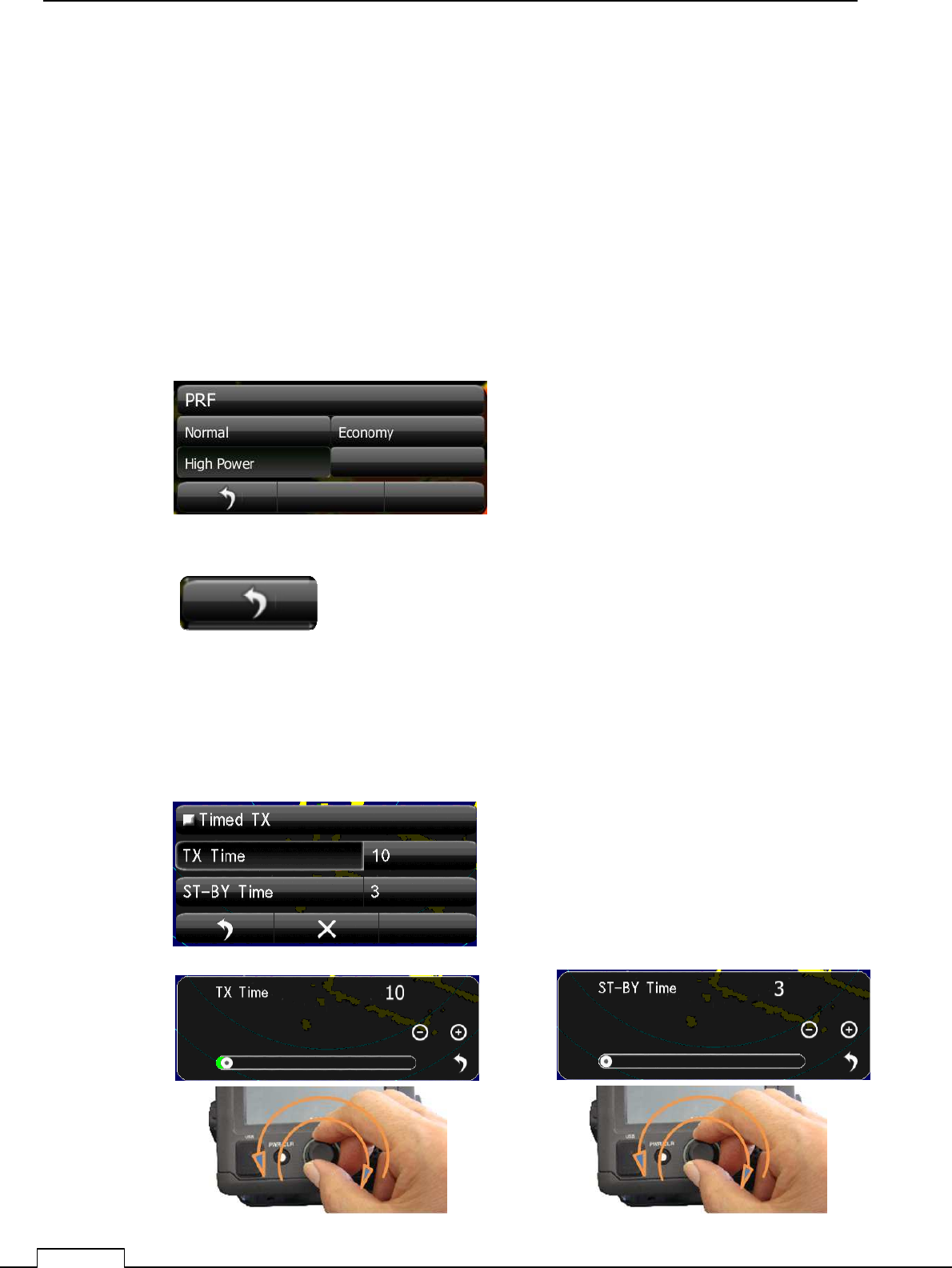
8-3-4 ECONOMY MAGNETRON SETUP (PRF , PULSE LENGTH)
The life of magnetron proportion to the total transmitting pulse power.
Low power transmission makes magnetron life more longer.
Selection
Normal: It is the usual factory setup. Usually, this is chosen.
Economy: Selected the shorter pulse, repeat frequency is also selected lowest 650 Hz.
The life of a magnetron keeps more longer time.
Sensitivity is decrease somewhat from Normal.
High Power: High sensitivity high performance.
8-3-5 TIMED TX
The life of magnetron proportion to the total transmitting pulse power.
Timed TX can save magnetron life longer.
return to the menu
Select and Tap
Chapter 8 DETAIL RFORMANCE SETTING
111
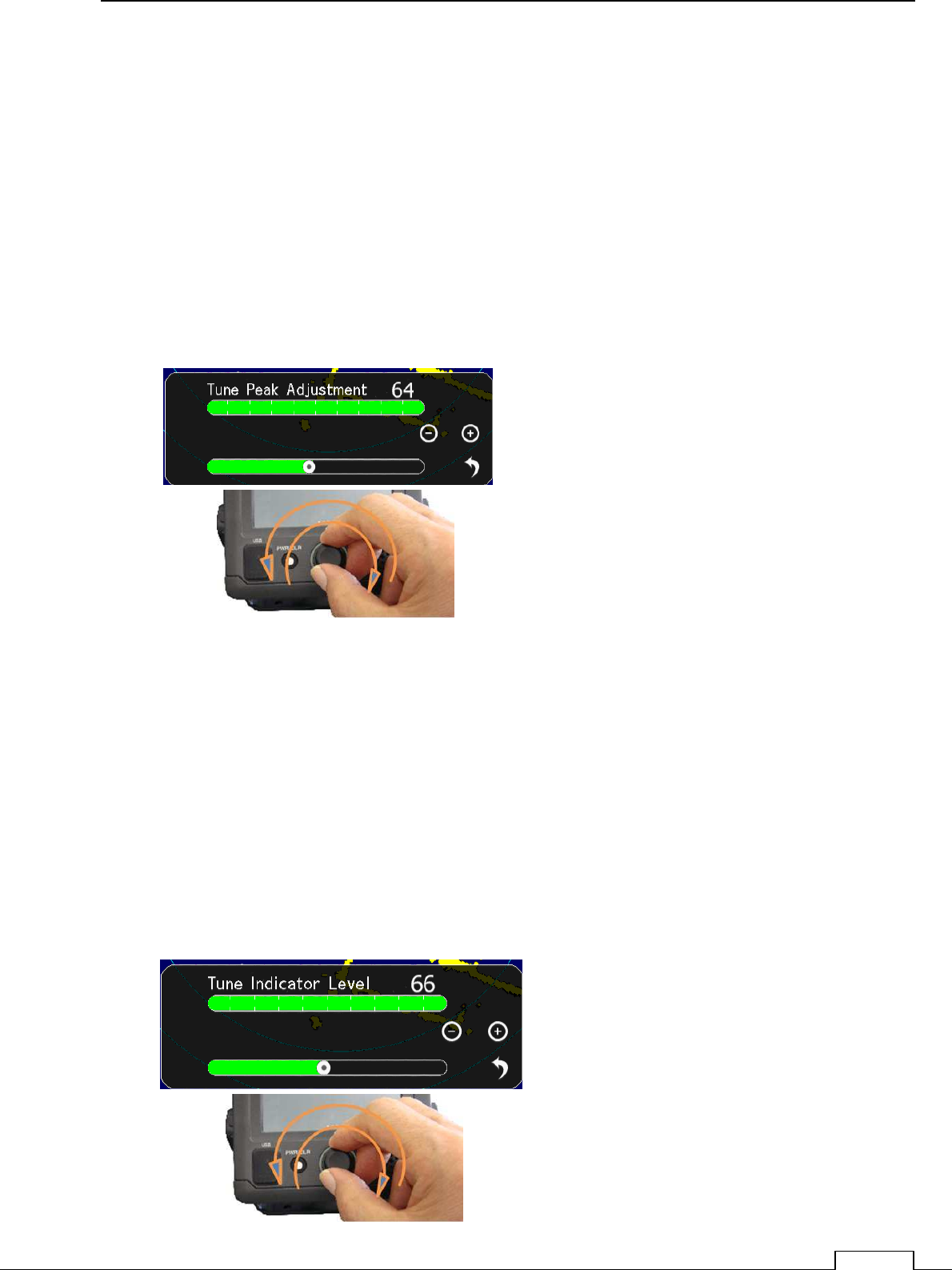
8-3-6 TUNE PEAK LEVEL
Normally, adjustment is not necessary.
(In case of adjustment the tuning peak point is shifted from maximum echo point.)
This adjustment must be done with (8-3-7 Tuning indicator) alternately.
Set RANGE at 24NM
Display tuning level indicator menu.
Tune maximum echo point.
At this point adjust tuning level, so as to seen within the green bar.
Adjusting data is 0 to 127
.
8-3-7 TUNE INDICATOR LEVEL
Normally, adjustment is not necessary.
(Adjust ,in case of tuning level is too low.)
Set RANGE at 24NM
Display the Tune Indicator menu.
Tuning region is 0 to 127
NOTE! If tuning level is too excess setting, can’t work automatic tuning function.
Adjust the tuning level bar moves within 80 to 90%.
Chapter
8
DETAIL PERFORMANCE SE
TTING
112
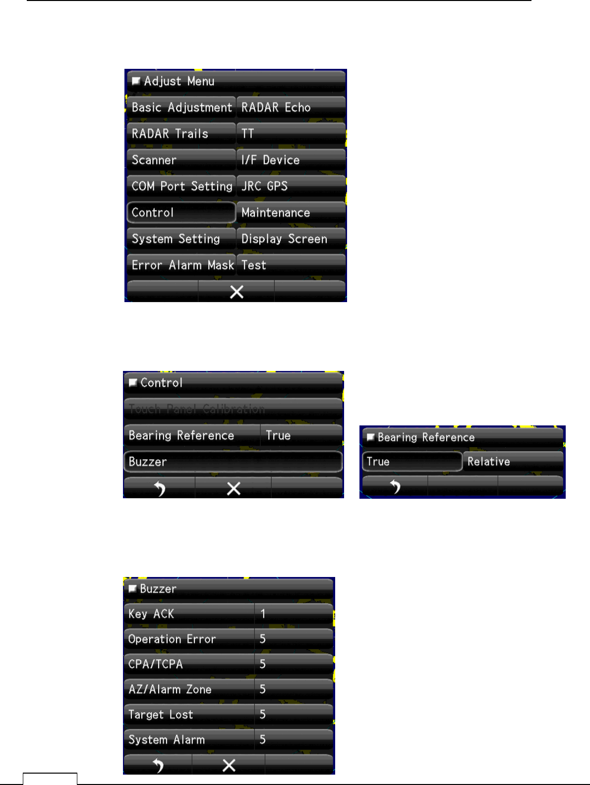
8-4 CONTROL
8-4-1 BEARING REFERENCE
8-4-2 BUZZER
Select Bearing Mode
True or Relative
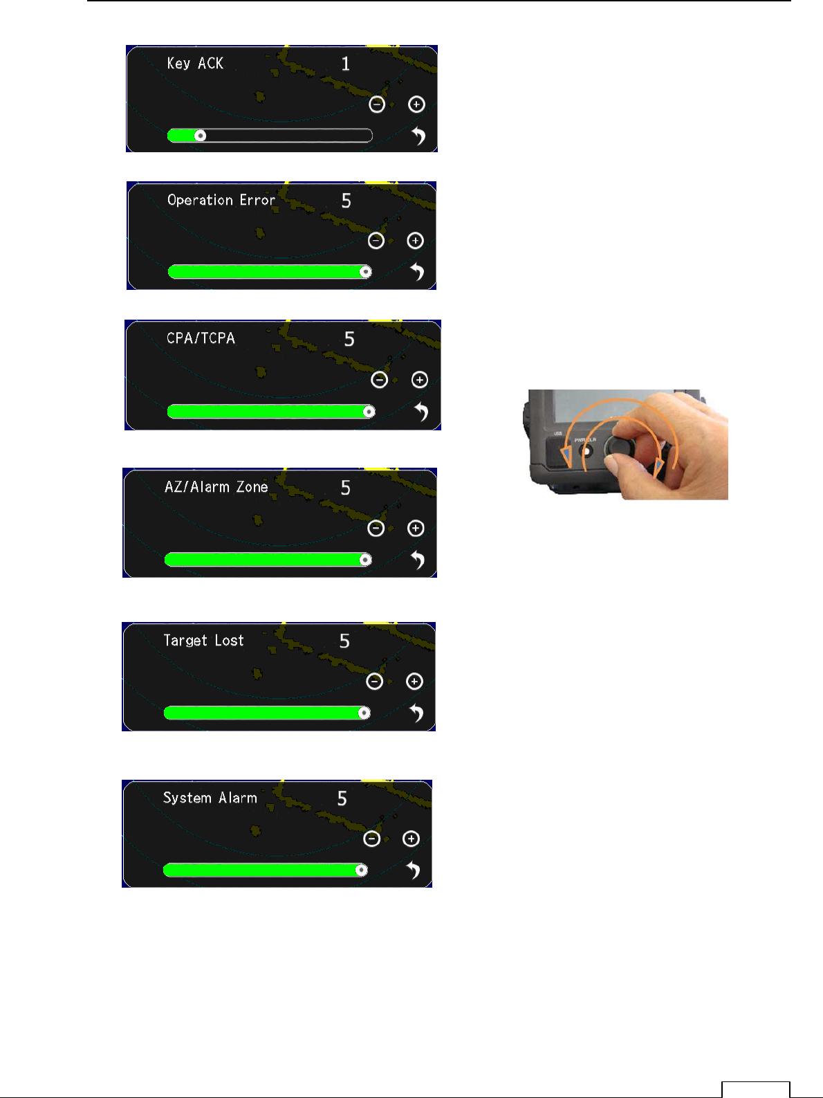
Set up the Buzzer sound Level.
Chapter 8 DETAIL RFORMANCE SETTING
113
Set up the Every sound Level.
Chapter
8
DETAIL PERFORMANCE SE
TTING
114
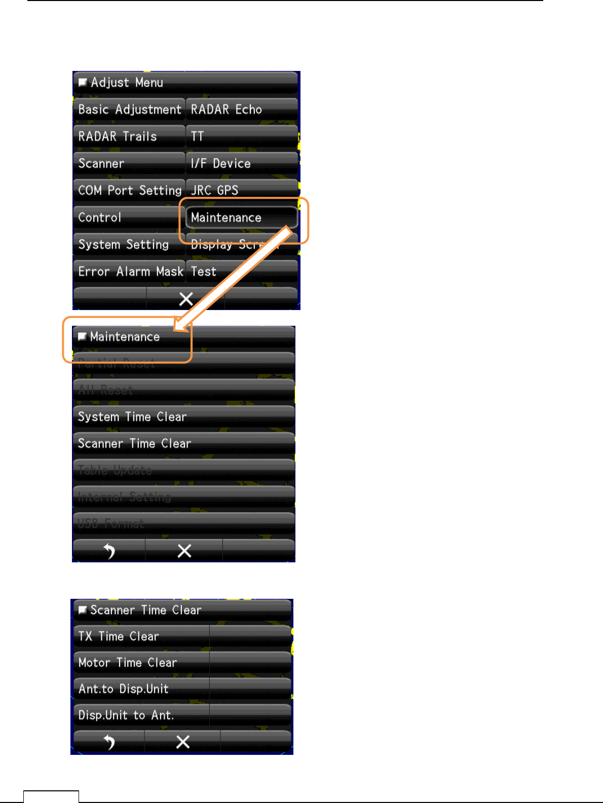
8-5 MAINTENANCE SETTING
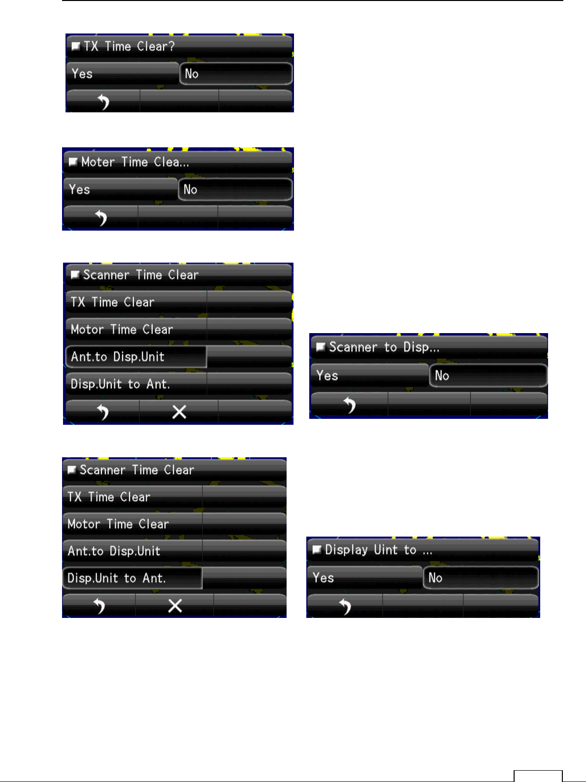
8-5-1 SYSTEM TIME CLEAR
8-5-2 SCANNER TIME CLEAR
Clear System time
Clear Scanner time.
Chapter 8 DETAIL RFORMANCE SETTING
115
Chapter
8
DETAIL PERFORMANCE SE
TTING
116
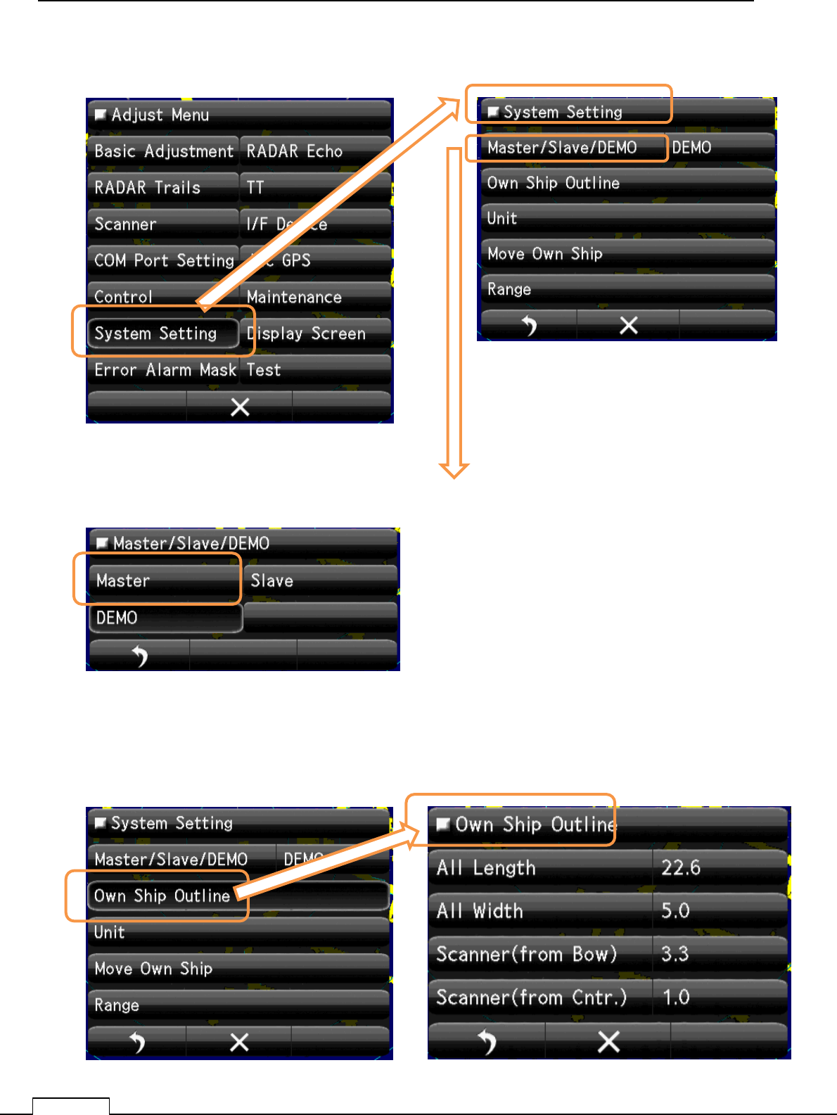
8-6 SYSTEM SETTING
8-6-1 MASTER/SLAVE/DEMO
8-6-2 Own Ship Outline
Set up the operating mode.
Mode selection of display.
Master: control scanner.(Stand alone.).
Slave: Receive another radar signal and display. can’t
control scanner.
Demo: When use as carrying out the demonstration
Select Master
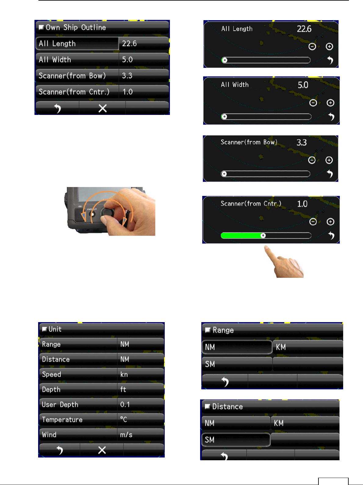
Set up the Own ship’s Outline, length and scanner position.
Chapter 8 DETAIL RFORMANCE SETTING
117
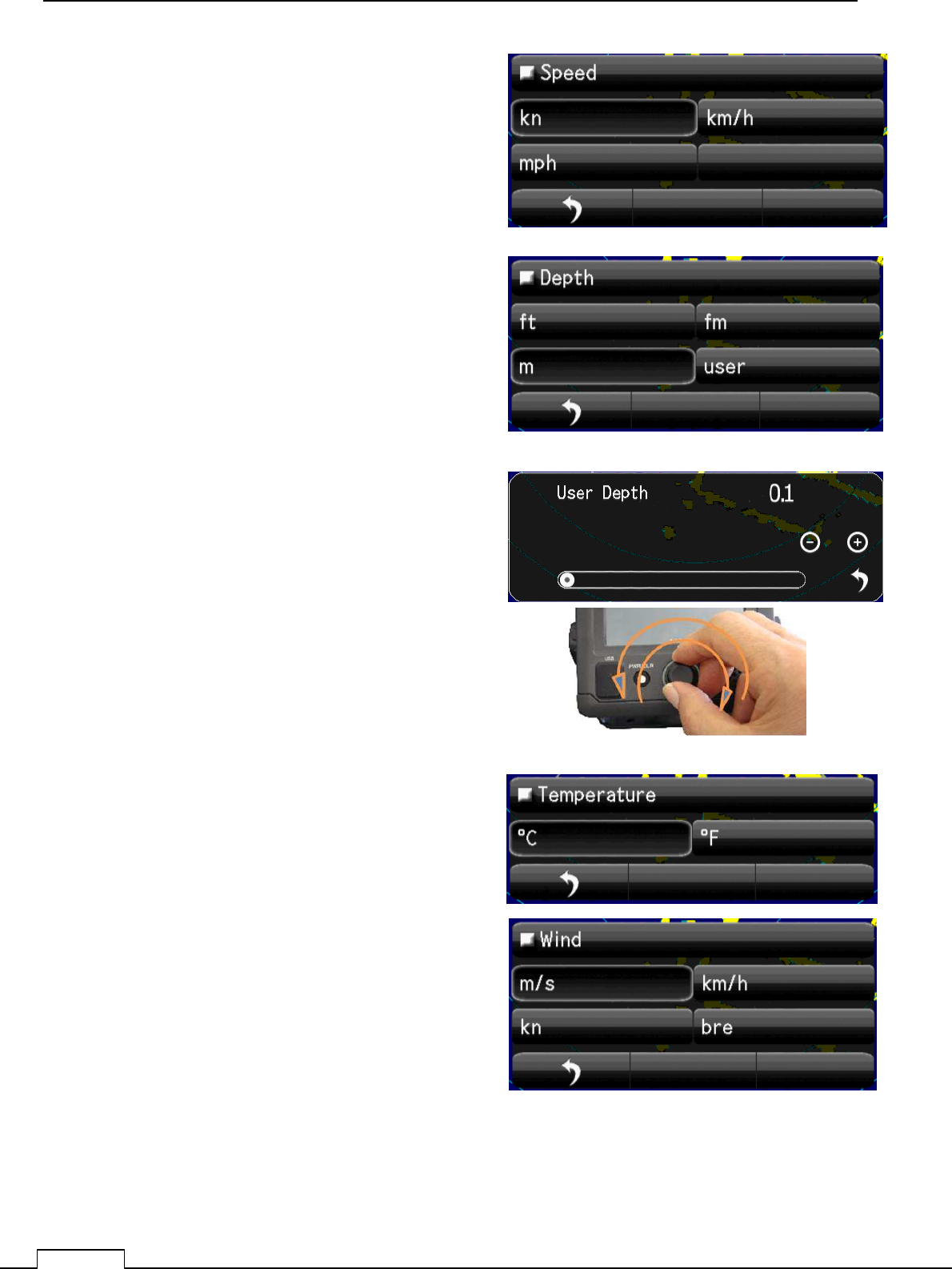
8-6-3 UNIT
Display units, such as distance, speed, depth of water, water temperature, and wind velocity.
“NM”,” km”,” ktn”, etc. are possible to set up.
Chapter
8
DETAIL PERFORMANCE SE
TTING
118
Chapter 8 DETAIL RFORMANCE SETTING
119
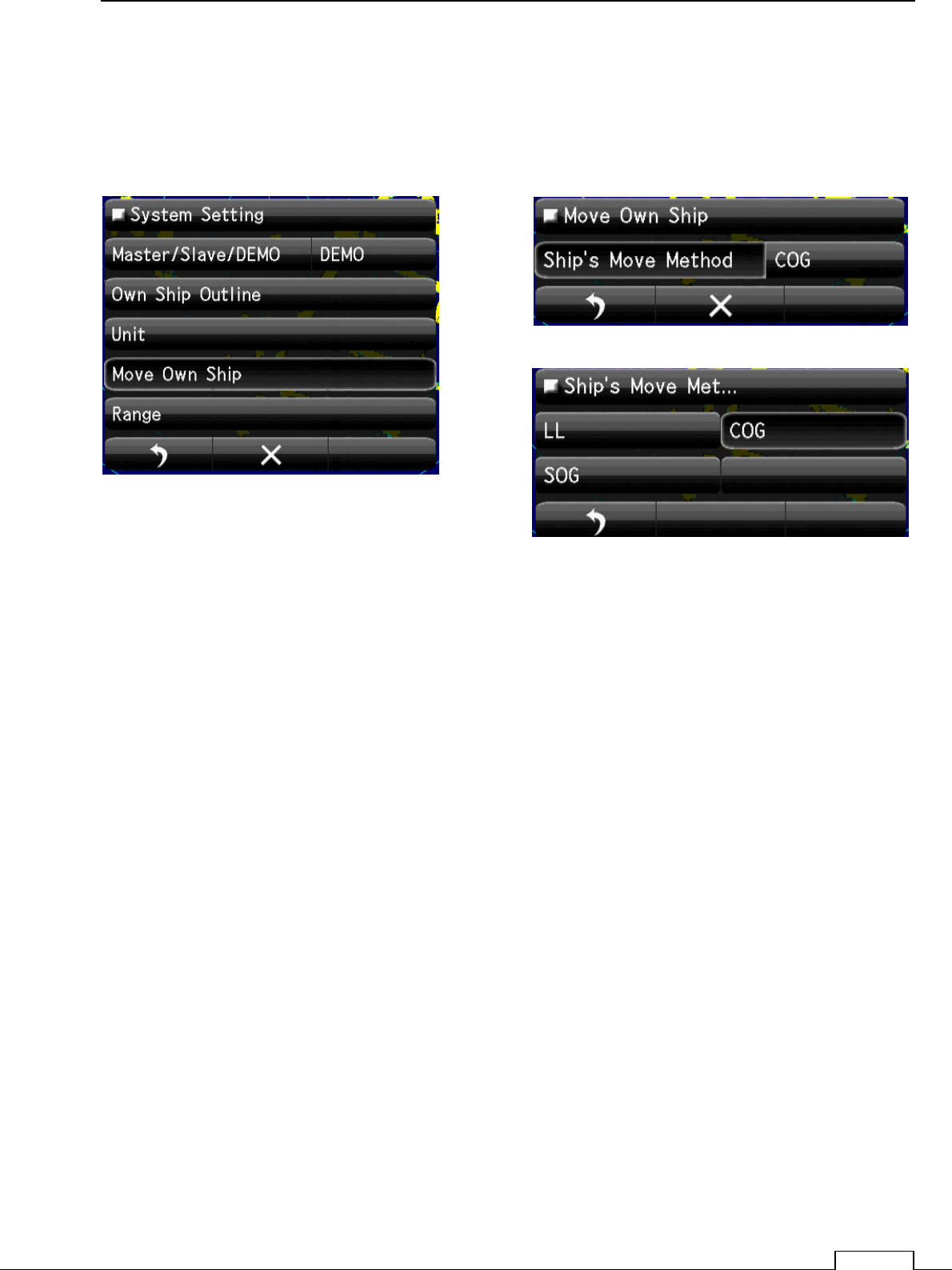
8-6-4 MOVE OWN SHIP
Means of Moving own ship.
Select
GPS, LOG, Dead Reckoning (dead-reckoning navigation), etc.
Chapter
8
DETAIL PERFORMANCE SE
TTING
120
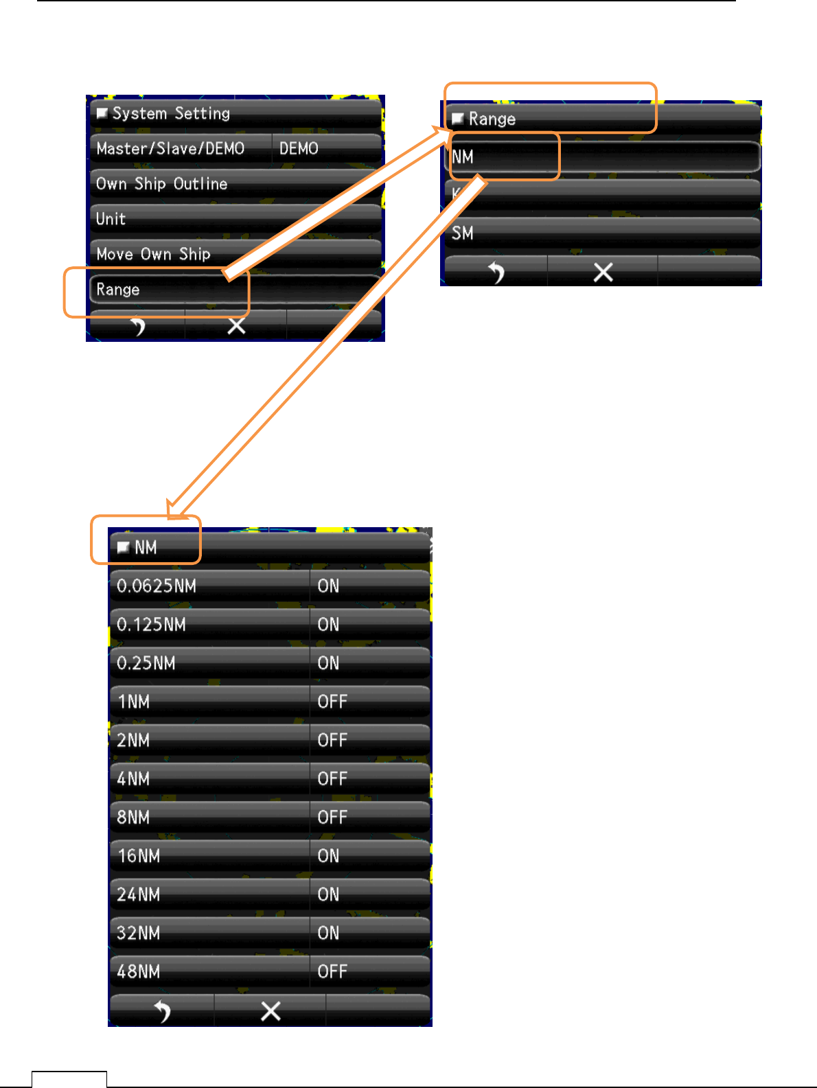
8-6-5 USE RANGE SELECT
Select the using unit. “NM”,”KM”,”SM”.
Select the using NM range “ON”.
Not using range, set up “OFF”.
Chapter 8 DETAIL RFORMANCE SETTING
121
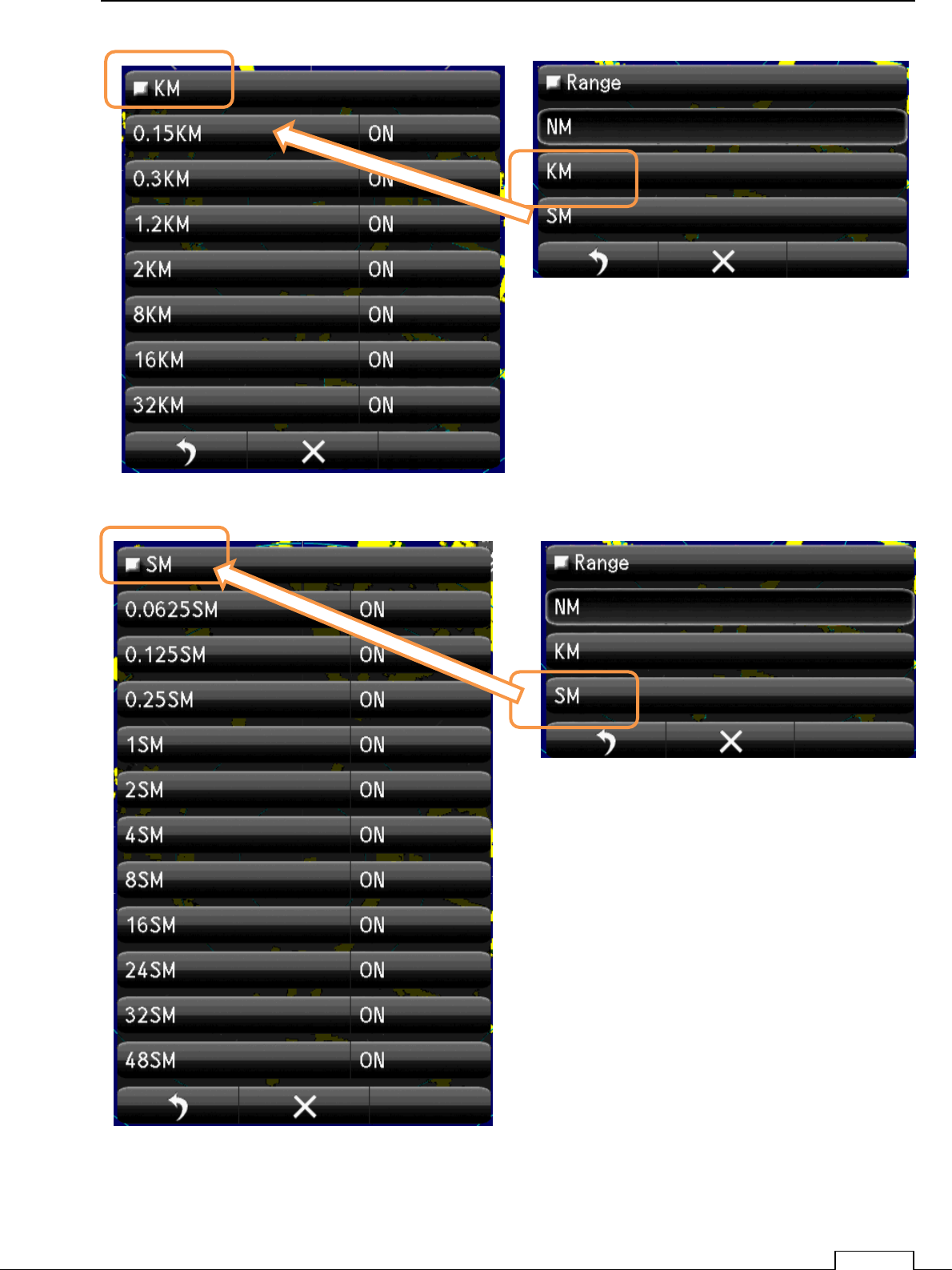
Select the using KM range “ON”.
Not using range, set up “OFF”.
Select the using SM range “ON”.
Not using range, set up “OFF”.
Chapter
8
DETAIL PERFORMANCE SE
TTING
122
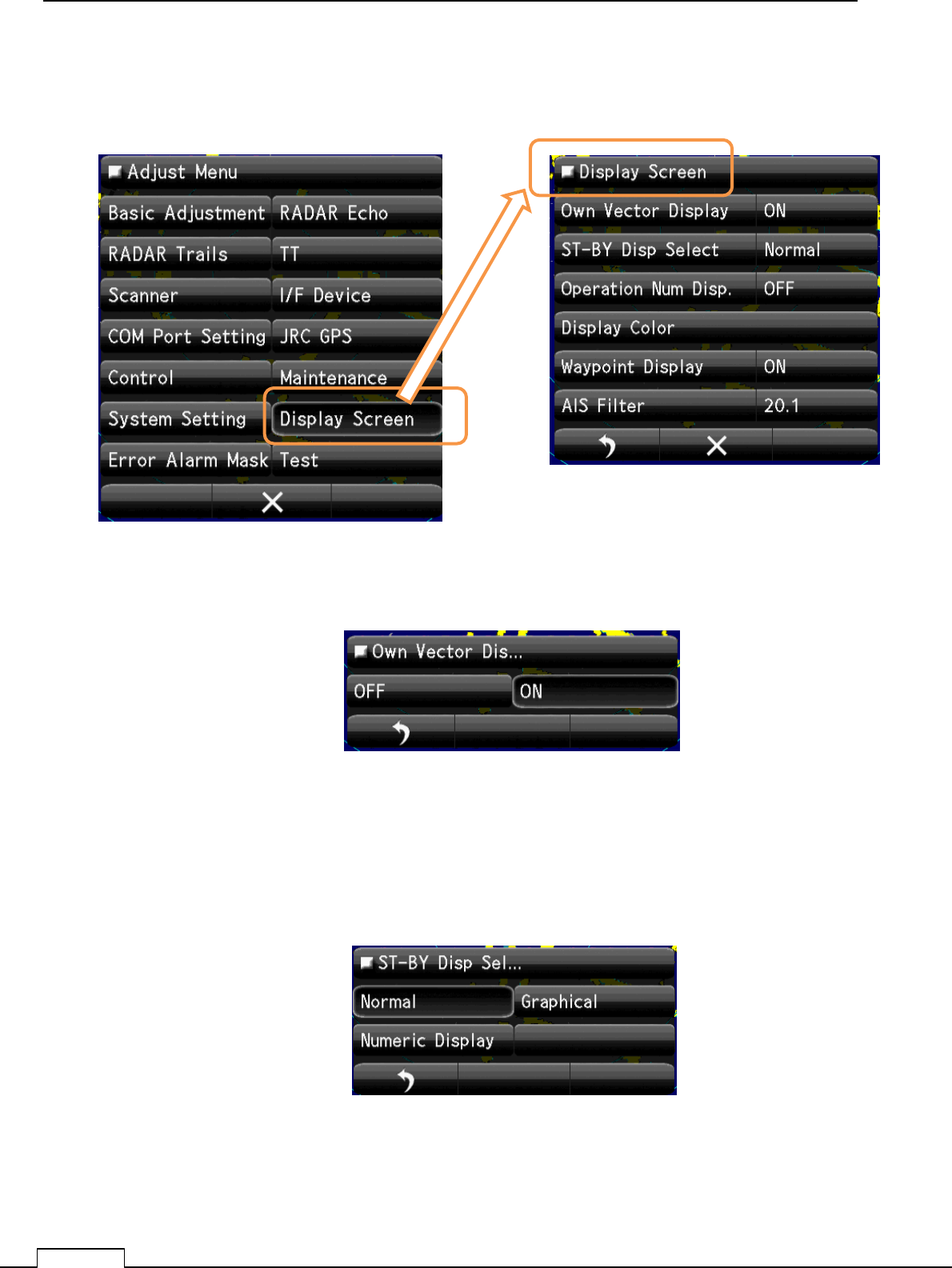
8-7 DISPLAY SCREEN
Various display setting..
8-7-1 OWN VECTOR DISPLAY
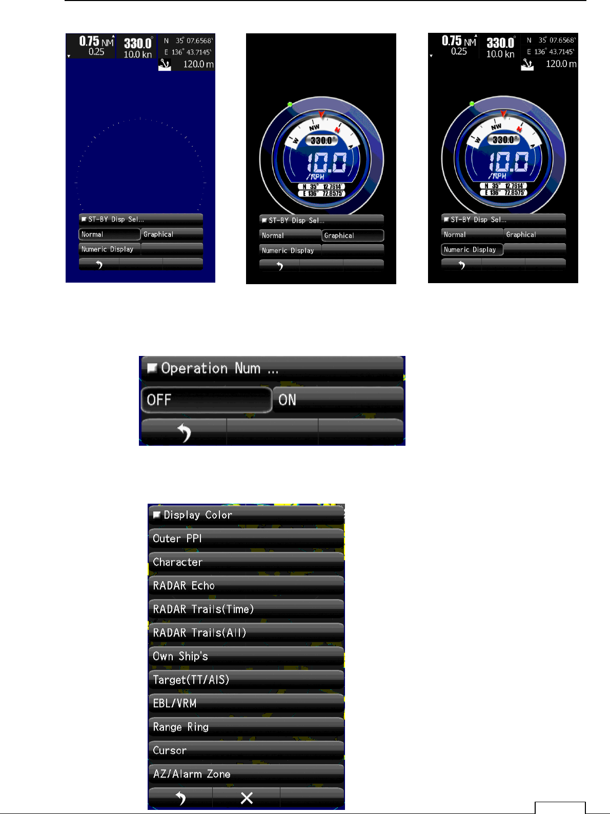
8-7-2 ST-BY DISP SELECT
Selections whether at stand by state, display the numeric data on screen or not.
Select the using SM range “ON”.
Not using range, set up “OFF#.
Select the Own Vector display ON or OFF.
Select the ST-BY Display. “Normal” “Graphical” “Numeric”.
Chapter 8 DETAIL RFORMANCE SETTING
123
8-7-3 OPERATION NUMERICAL DISPLAY
8-7-4DISPLAY COLOR
“Normal” “Graphical” “Numeric”.
Select the Display. OFF or ON
Setting of screen color.
Chapter
8
DETAIL PERFORMANCE SE
TTING
124
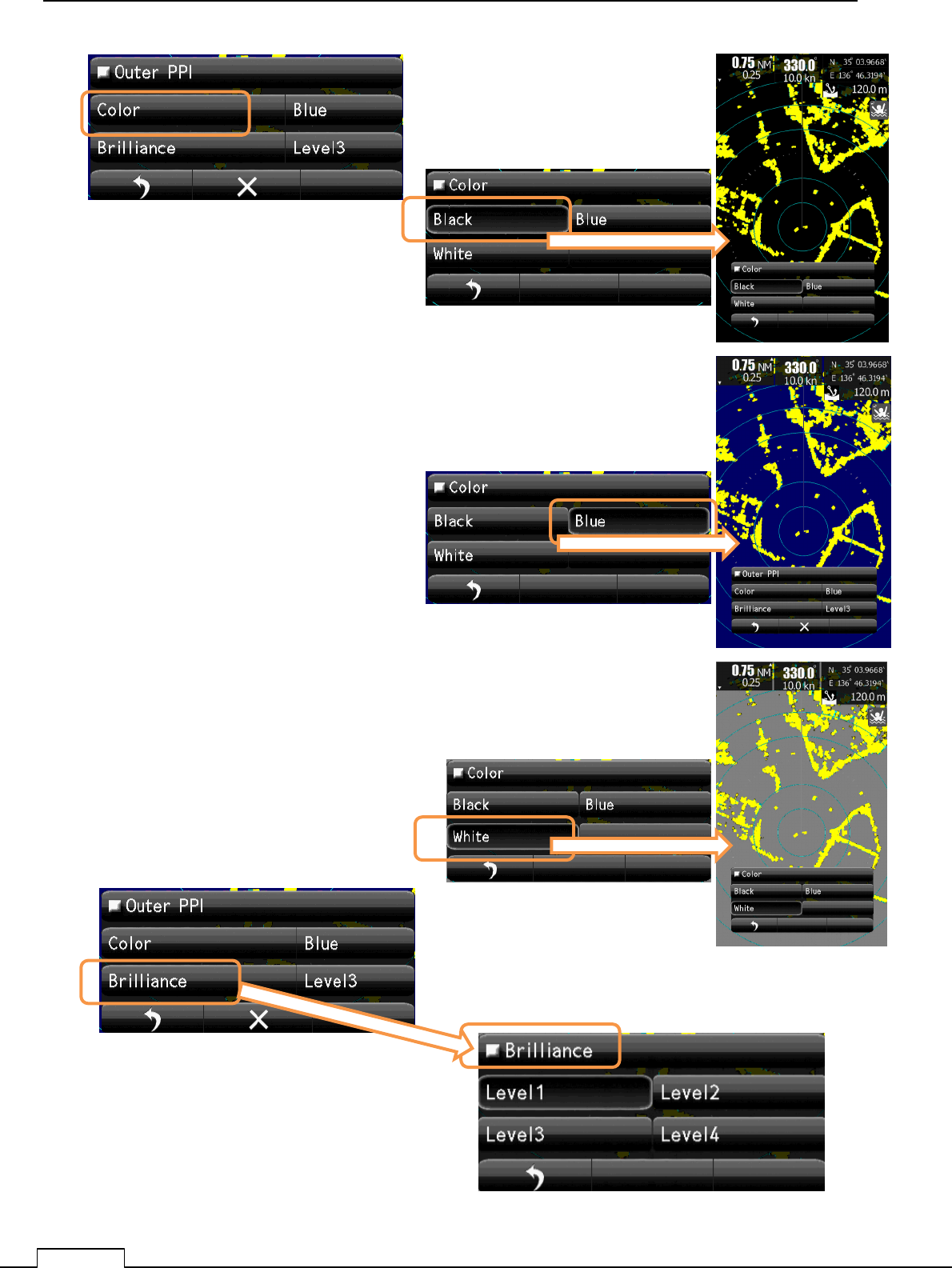
Black screen color.
Select Brilliance Level
Blue screen color.
White screen color.
Chapter 8 DETAIL RFORMANCE SETTING
125
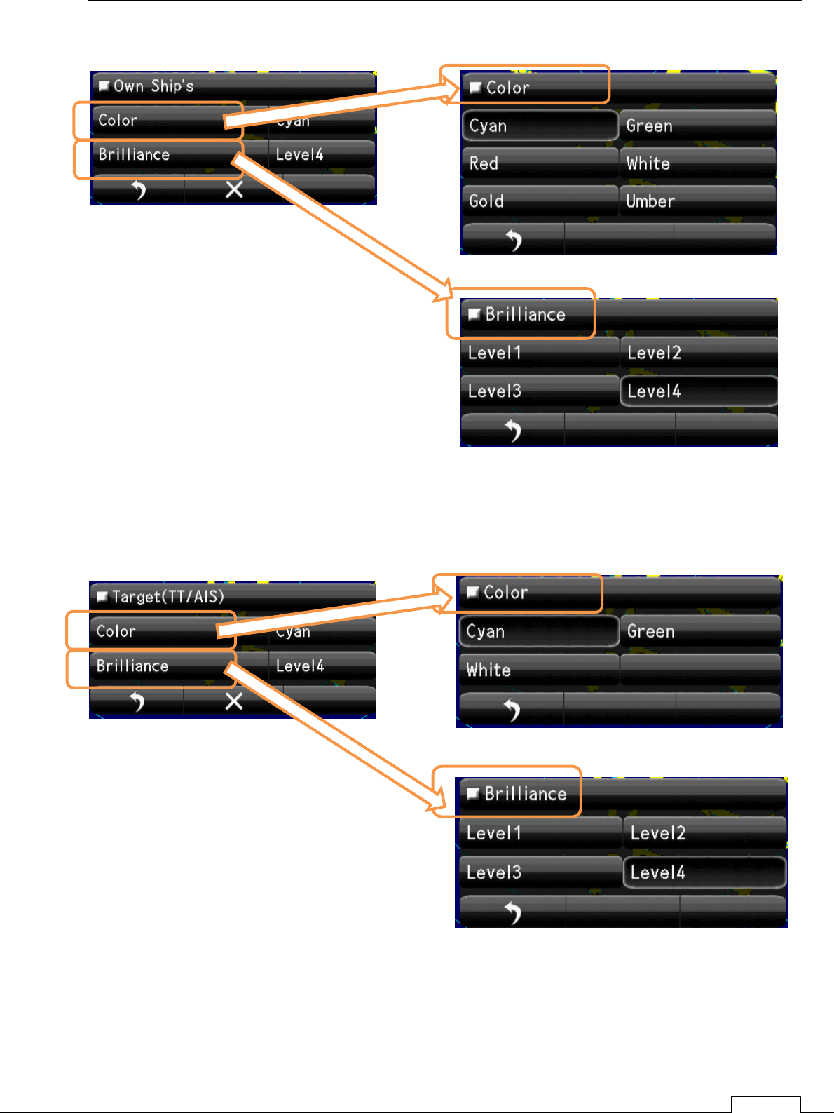
Select Color
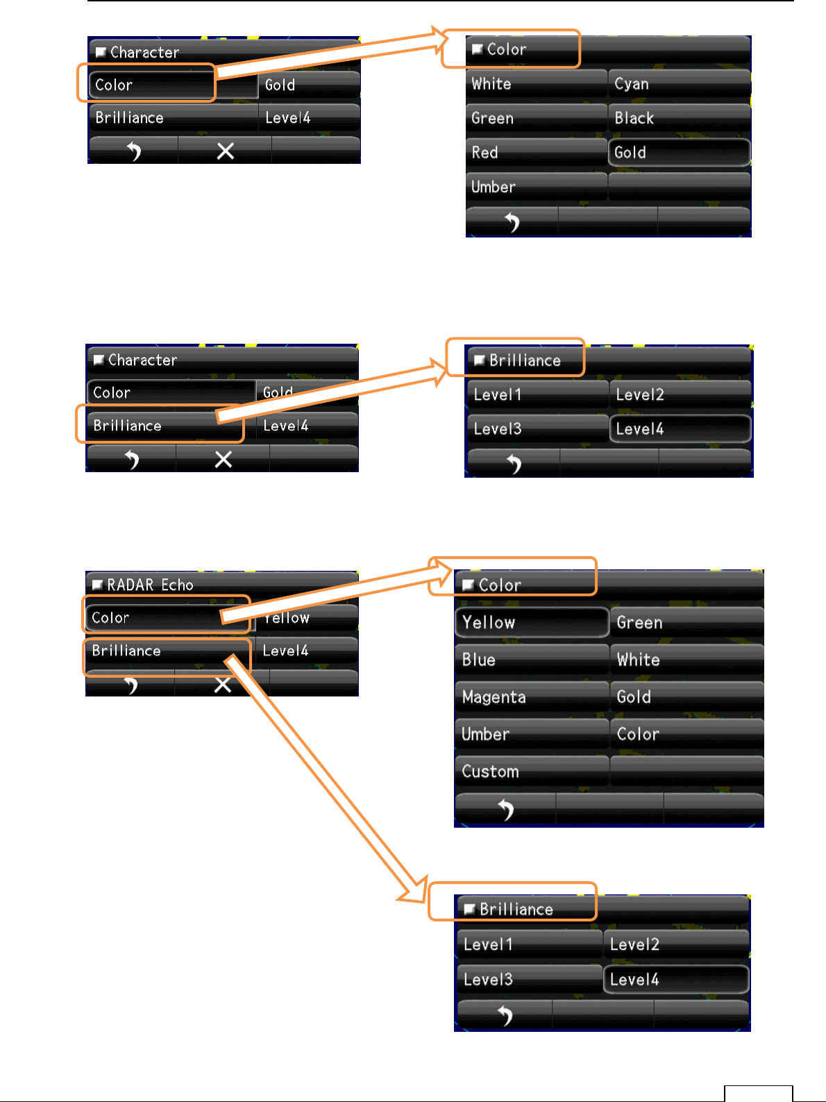
Select Character Color
Select Brilliance. Select Brilliance. Level.
Select Brilliance. Level.
Select Echo Color
Chapter
8
DETAIL PERFORMANCE SE
TTING
126
Select Brilliance. Level.
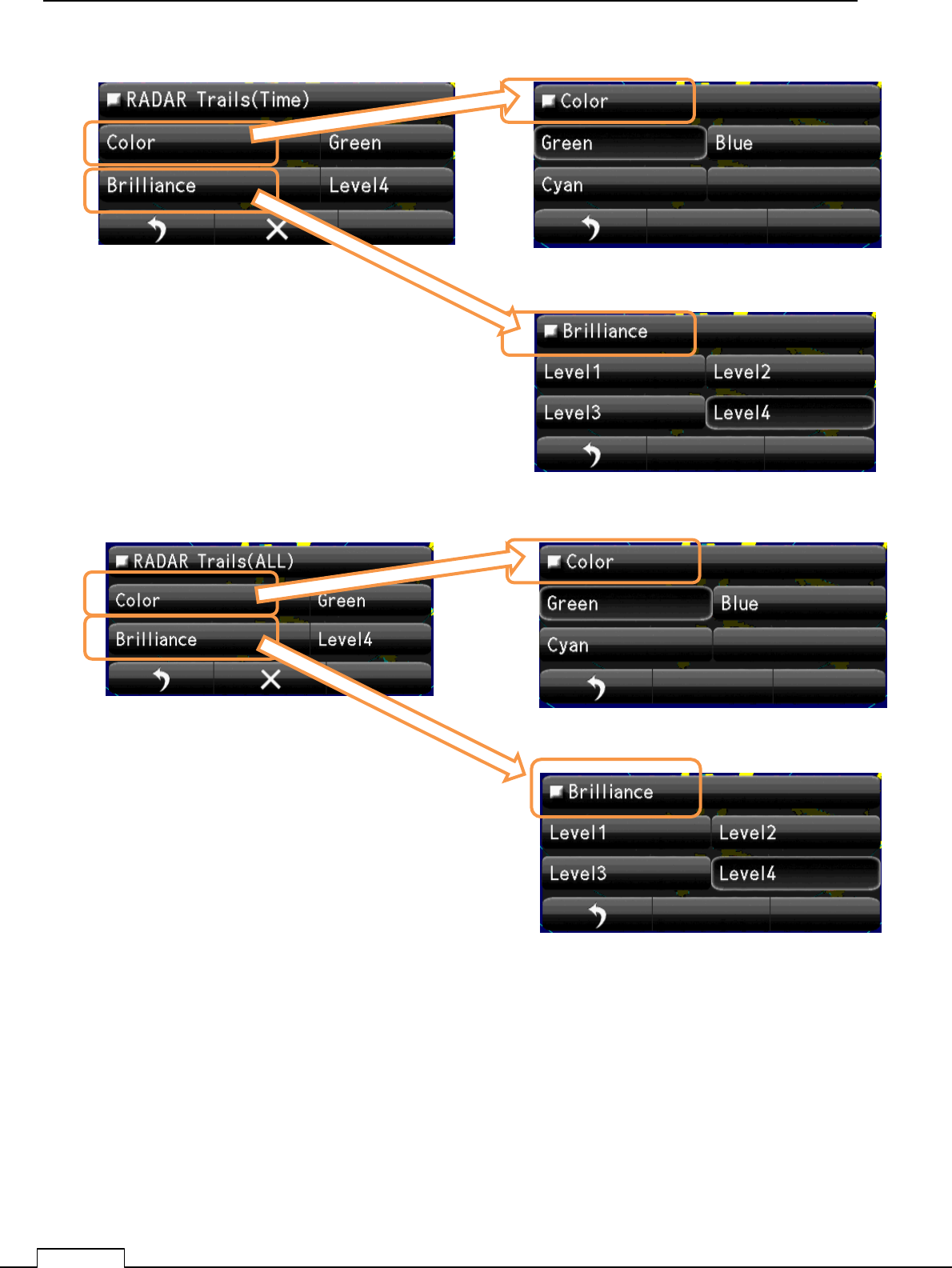
Select Trails(Time) Color
Select Brilliance. Level.
Select Trails(All) Color
Chapter 8 DETAIL RFORMANCE SETTING
127
Select Brilliance. Level.
Select Own Ships Color
Select Brilliance. Level.
Select Target (TT/AIS) Color
Chapter
8
DETAIL PERFORMANCE SE
TTING
128
Select Brilliance. Level.
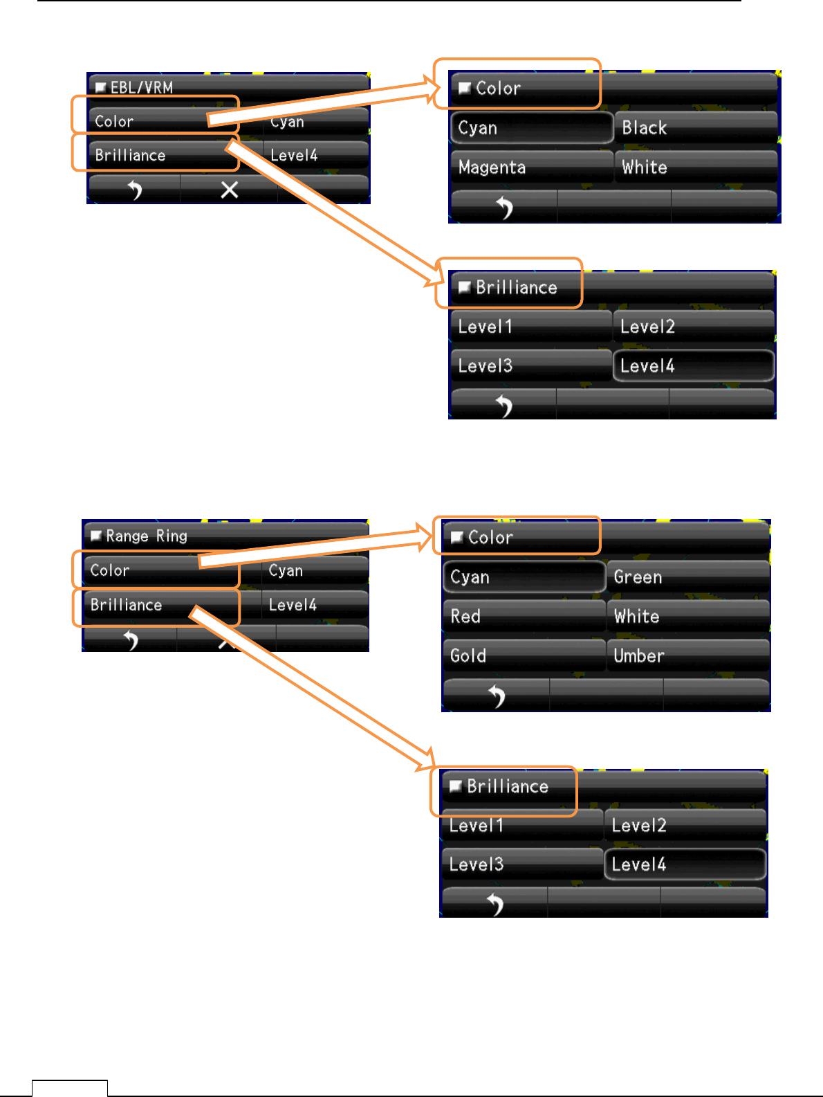
Select EBL/VRM Color
Select Brilliance. Level.
Select Range Ring Color
Chapter 8 DETAIL RFORMANCE SETTING
129
Select Brilliance. Level.
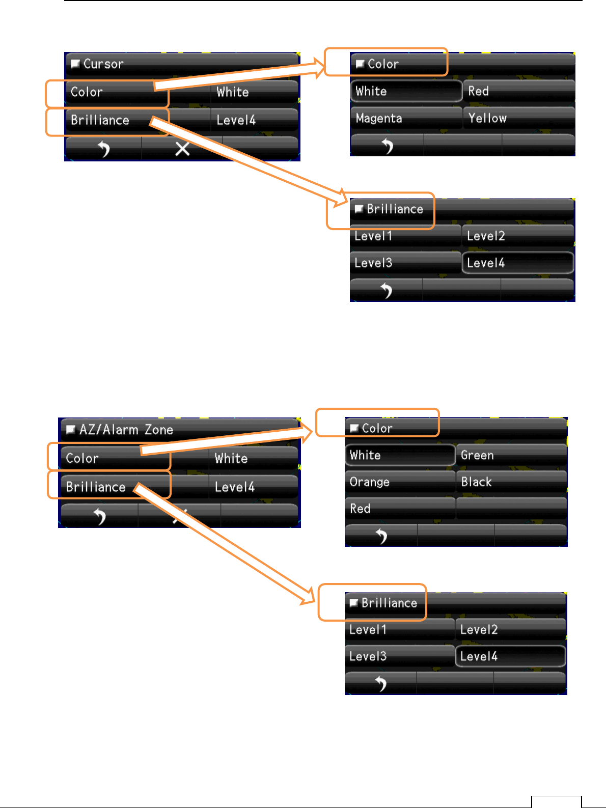
Select Cursor Color
Select Brilliance. Level.
Select AZ/Alarm Color
Chapter
8
DETAIL PERFORMANCE SE
TTING
130
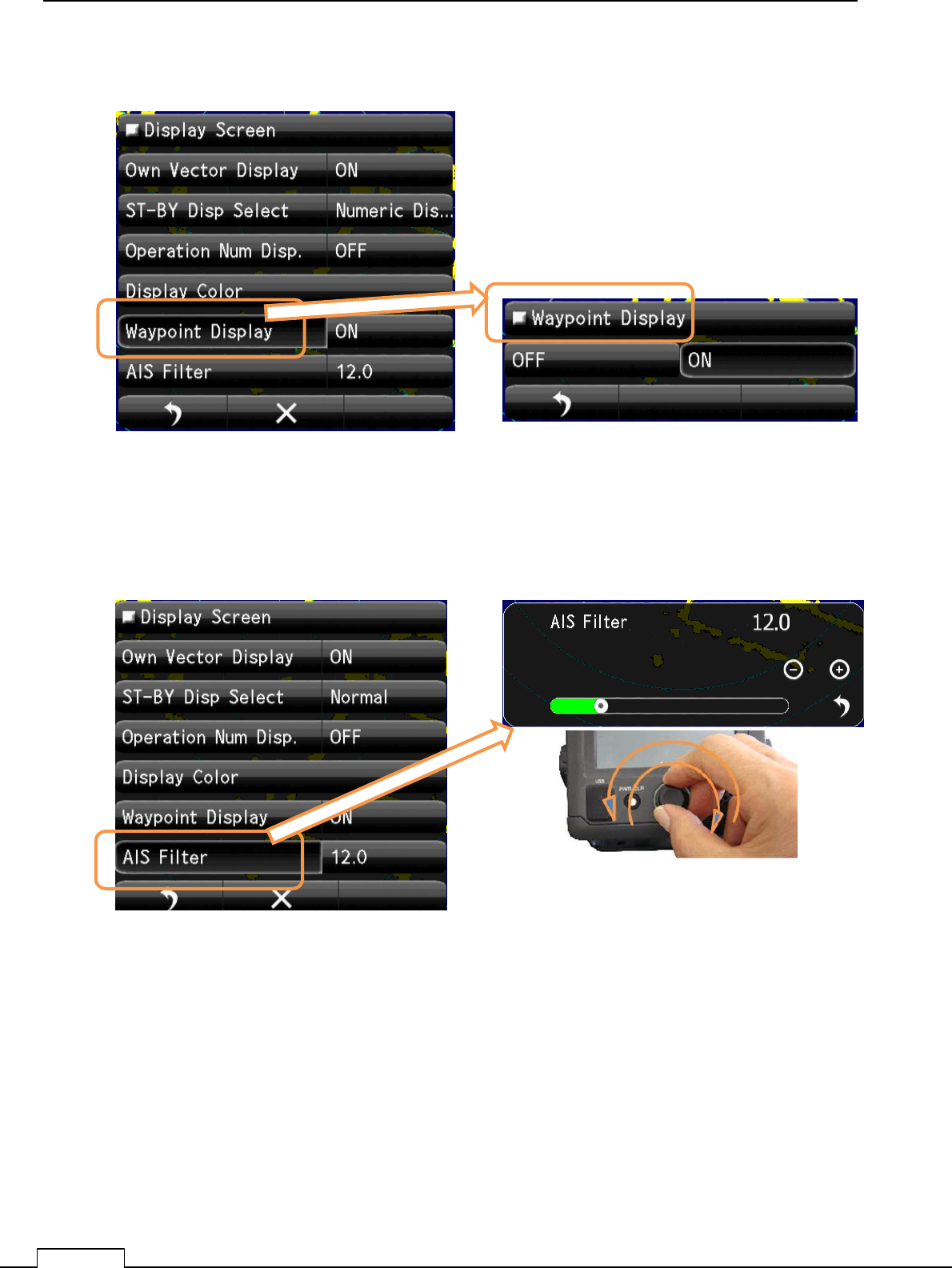
8-7-5WAYPOINT DISPLAY
8-7-6AIS FILTER
Select Waypoint Display. Select Waypoint Display “ON” or ”OFF”.
Set up AIS Filter Range.
Select AIS Filter
Chapter 8 DETAIL RFORMANCE SETTING
131
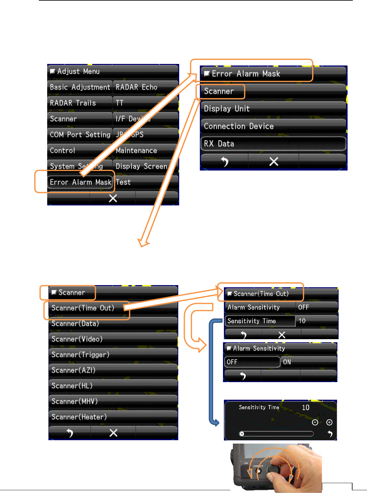
8-8 ERROR ALARM MASK
Ignore the unnecessary error signal’s alarm.
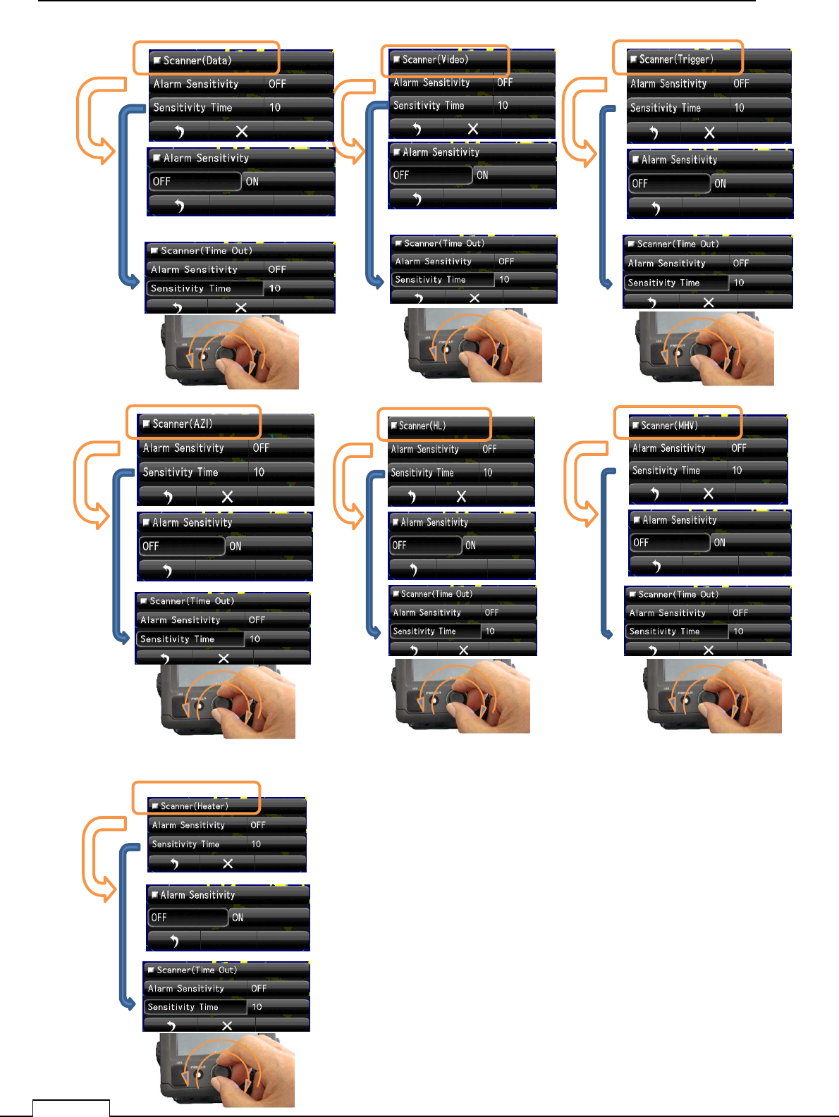
8-8-1 SCANNER
The error signal generated in the scanner.
Chapter
8
DETAIL PERFORMANCE SE
TTING
132
Scanner(Data)
Scanner(Video) Scanner(Trigger)
Scanner(Azi) Scanner(HL) Scanner(MHV)
Scanner(Heater)
Chapter 8 DETAIL RFORMANCE SETTING
133
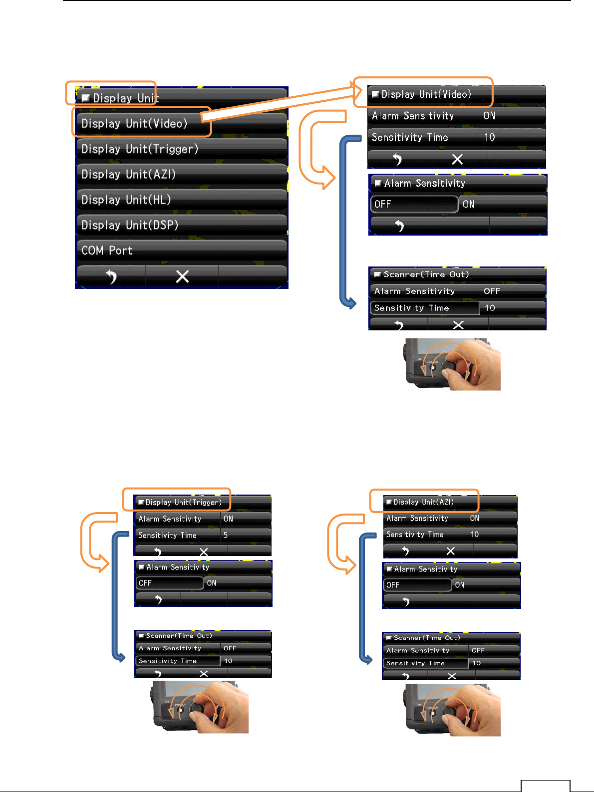
8-8-2 DISPLAY UNIT
The error signal generated in the display unit.
Display Unit(Video)
Display Unit(Trigger) Display Unit(AZI)
Chapter
8
DETAIL PERFORMANCE SE
TTING
134
]
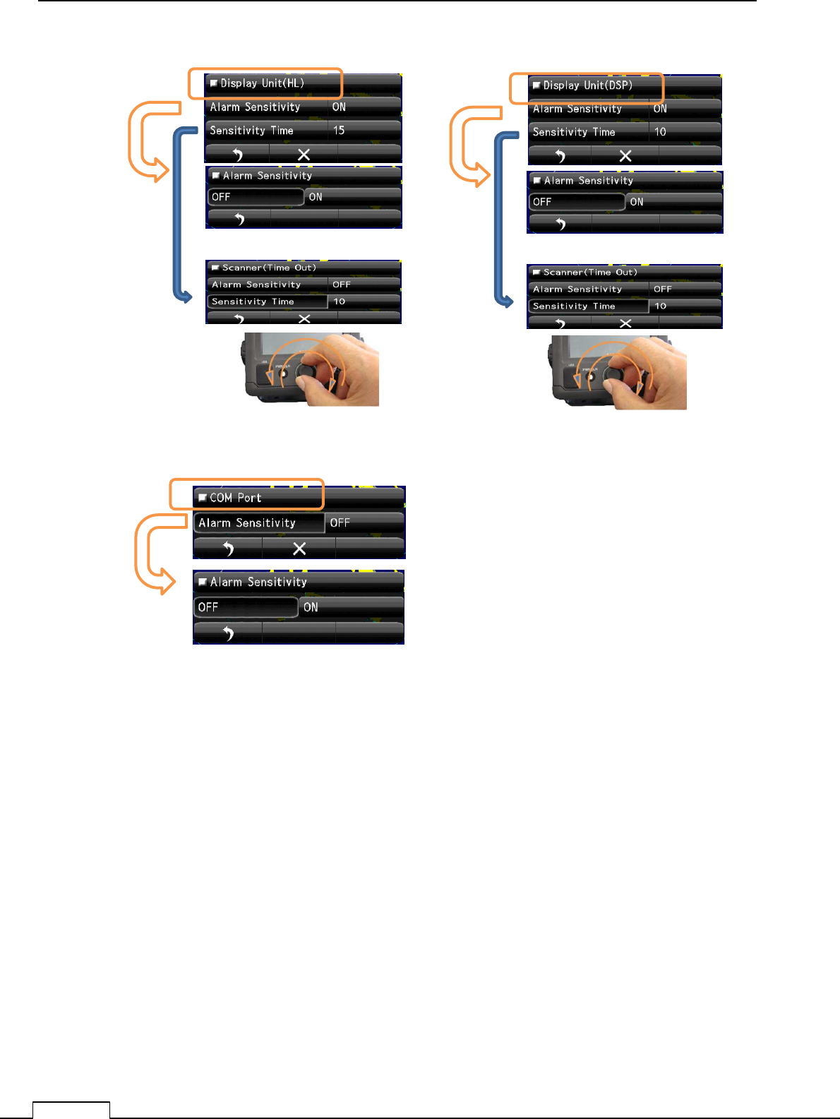
Display Unit(HL) Display Unit(DSP)
COM Port
Chapter 8 DETAIL RFORMANCE SETTING
135
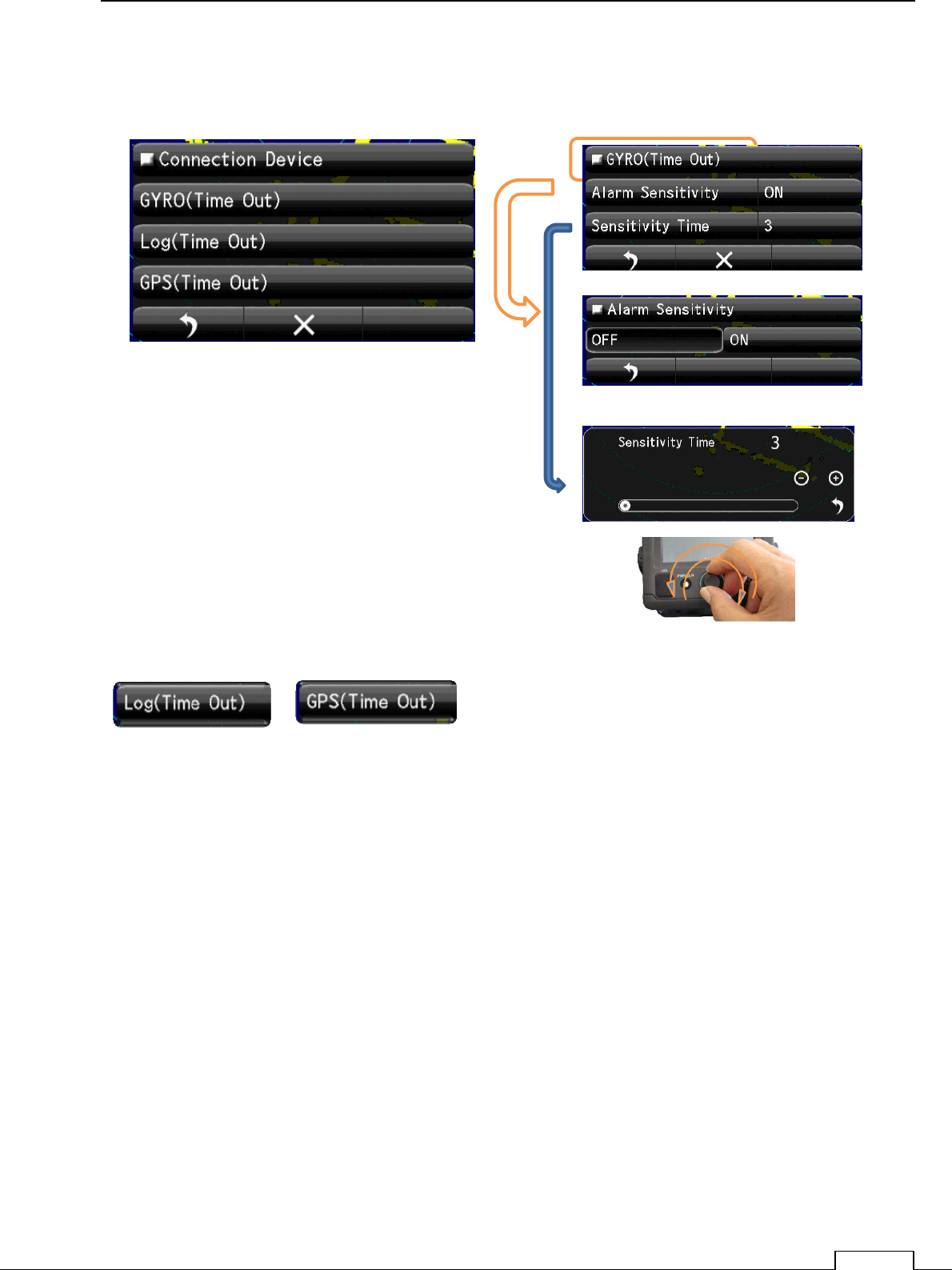
8-8-3 CONNECTION DEVICE
The error signal generated about the connected device.
Gyro(Time Out)
Log (Time Out) GPS (Time Out) are the same method.
Chapter
8
DETAIL PERFORMANCE SE
TTING
136
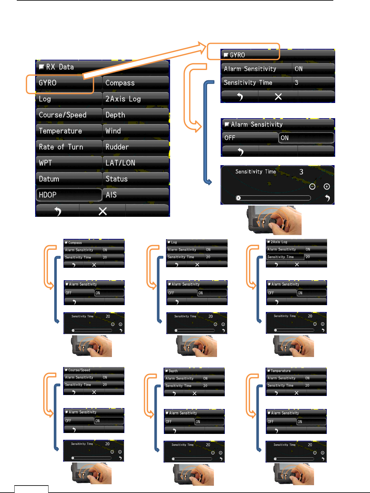
8-8-4 RX DATA
The error signal about receiving data from another equipment.
Compass data Alarm Log data Alarm 2Axis Log data Alarm
Chapter 8 DETAIL RFORMANCE SETTING
137
Course / Speed data Alarm Depth data Alarm Temperature data Alarm
Wind data Alarm Rate of Turn data Alarm 2Rudder data Alarm
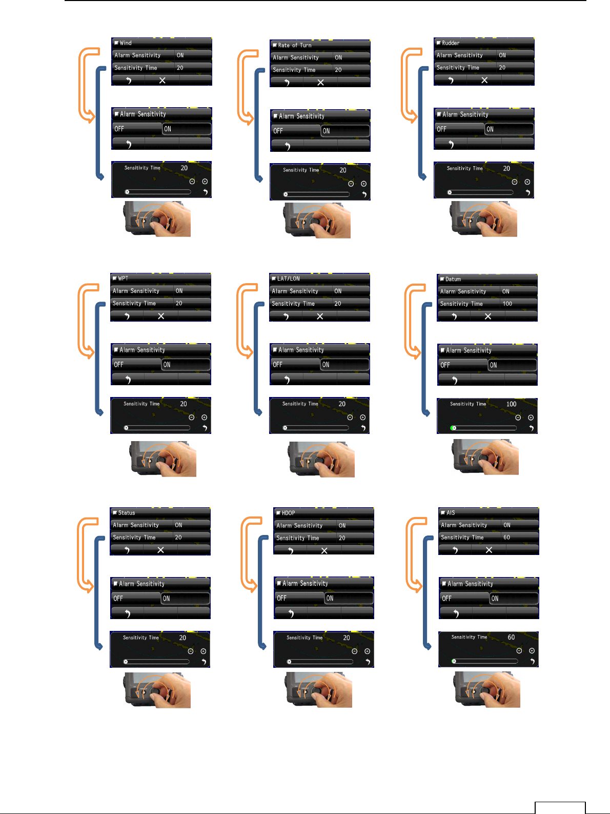
WPT data Alarm LAT/LON data Alarm Datum data Alarm
Status data Alarm HDOP data Alarm AIS data Alarm
Chapter 4 MEASURE THE SURROUND SHIP
61
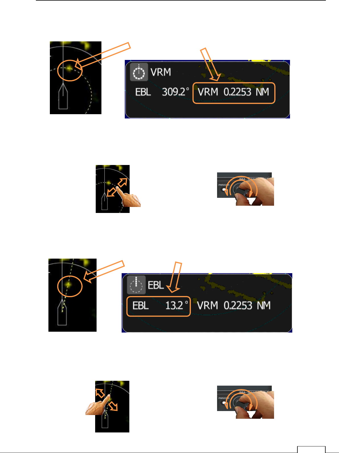
4-1-3 EXAMPLE OF VRM FUNCTION
* The example of a display of VRM
Close menu automatically after 10seconds.
Down side on screen, “RNG” display own ship to target RANGE(nm).
4-1-4 EXAMPLE OF EBL FUNCTION
* The example of a display of EBL
Close menu automatically after 10seconds.
,
Coincident target to VRM, Range of own ship to target is displayed.
Coincident target to EBL, BEARING of own ship to target is displayed.
Flick of the VRM line;
change the ring size, kept its data at tap off position. Rotate the rotary knob
with monitoring VRM line.
Or
How to change the VRM
Flick of the EBL line;
change the line bearing, kept its data at tap off position.
Rotate the rotary knob
with monitoring EBL line.
Or
How to change the EBL

Chapter 4 MEASURE THE SURROUND SHIP
62
****
********
****
FOR REFERENCE
****
********
****
ABOUT THE DATA READ OUT WHEN MEASURE USING EBL /VRM
The RADAR can measure Target position as BEARING(degree°
°°
°) and RANGE(nm).
BEARING is two way to measure.
①
①①
①One is the RELATIV BEARING which is measured from Own ship heading line.
②
②②
②Another is ABSOLUTE BEARING which is measured from the NORTH line
Of cause, ABSOLUTE BEARING is calculated by (RELATIV BEARING+GYRO BEARING).
So, ABSOLUTE BEARING is necessary the signal from GYRO or GPS compass.
☆
☆☆
☆In case of no external bearing signal, display only RELATIV BEARING mode.
☆
☆☆
☆(TT)Target Tracking function and display AIS symbol is necessary the GYRO
or GPS compass signal.
When GYRO or GPS compass signal are received, normally Azimuth is measured
based on from the NORTH(ABSOLUTE AZIMUTH).
This Radar’s scanner microwave BEAM WIDTH is about 5degrees.
So every target echo has more than 5degrees width for bearing direction.
For above reason, In case of read out the target azimuth, set EBL line to the center of the
target echo.
Target echo RANGE is measured by the distance from Own ship for any azimuth.
Target echo size is proportion to pulse length which own ship was transmit.
In case of MEASURE SHORT RANGE ECHO using VRM, set ring to the echo’s nearest
point from Own ship.
At that point is the correct RANGE for any pulse length.
Chapter 5 USEFUL FUNCTIONS
63
Chapter 5 USEFUL FUNCTIONS
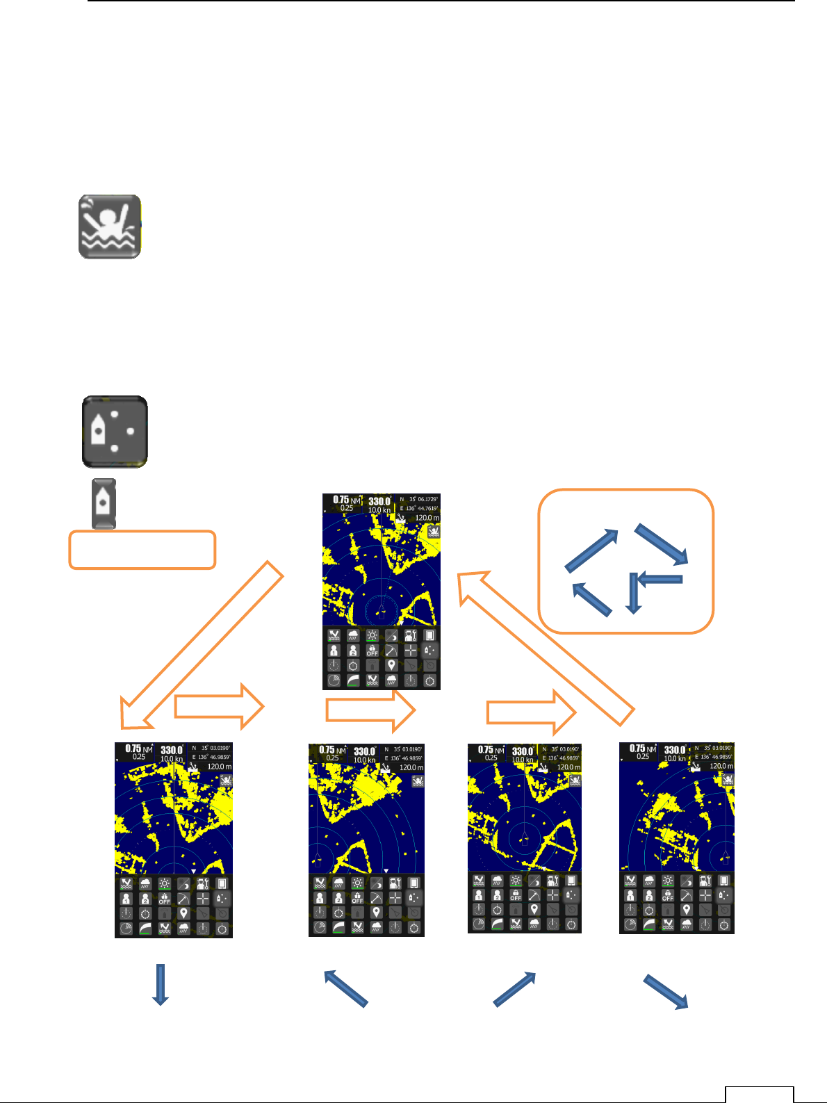
5-1 MOB (MAN OVER THE BOAT)
GPS signal and heading data (GYRO or GPS compass signal) are necessary.
Under navigation, if accident has happen (dropped person from the ship or anything).
Tap the MOB icon, then Radar remain that point’s longitude latitude in a moment.
And any time keep displays the plot symbol on screen.
For help the dropped person, anyway navigate the ship to MOB symbol position.
5-2 OFF-CENTER FUNCTION
Shift the own ship center is possible to shift for more wider area observation..
Each tap of the icon, will shift the own ship center one step to the next.
Own ship’s shifting trace is as follows.
downward left upward right
Own ship position
Trace Own ship position
Chapter 5 USEFUL FUNCTIONS
64
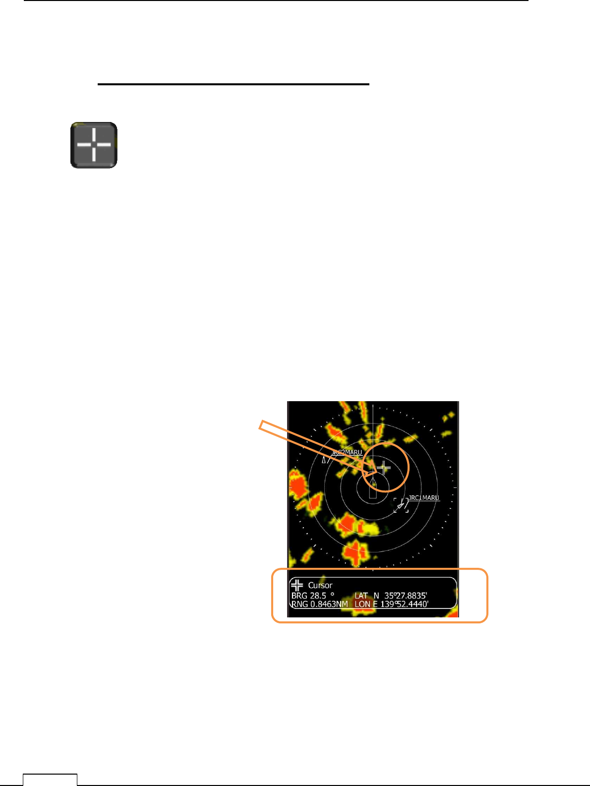
5-3 CURSOR FUNCTION
CURSOR FUNCTION IS ONLY TOUCH SCREEN
Using the cursor function can read out correct target information.
Tap cursor icon.
Tap the screen in some place, the cursor icon will come out of screen.
It’s display that point’s bearing and range on down side of screen.
If GPS signal is alive, that’s position’s Longitude, Latitude is displayed.
Numeric display is fade out from screen touch off after 5 seconds.
Tap screen will come out cursor onscreen.
Down side of screen displayed as follows.
“BEARING” BRG 28.5°
“RANGE” RNG 0.8463NM
In case GPS signal is connected.
“Latitude “ LAT N35° 27.8835’
“Longitude” LON E 139° 52.4440’
Numeric display is faded out from screen
touch off after 5 seconds.

Chapter 5 USEFUL FUNCTIONS
65
5-4 SETUP THE GUARD ZONE
(WATCH THE TARGET IN ALARM AREA)
Guard zone function detects the echo’s moving in warning area.
Alarm area can set in-alarm, or out-alarm both.
In alarm: Target echo is inside guard zone, generate the alarm sound.
Out alarm: Target echo go to outside of guard zone, generate the alarm sound.
Watching area is setting start point to end point of circle area.
Select alarm condition in-alarm or out-alarm.
****
********
****
FOR REFERENCE
****
********
****
Guard zone is move accordance with own ship’s movement.
For example, set front side of the own ship, start keep watching, and if ship
is crossing the setting area, automatically generate the alarm.
On the other hand, watch keeping sip is set inside the guard zone, if ship
were go outside the guard zone, automatically generate the alarm.
Crew can realize which ship was moved.
So, it is effective to use as watch keeping the fishing net or buoy.
Chapter 5 USEFUL FUNCTIONS
66
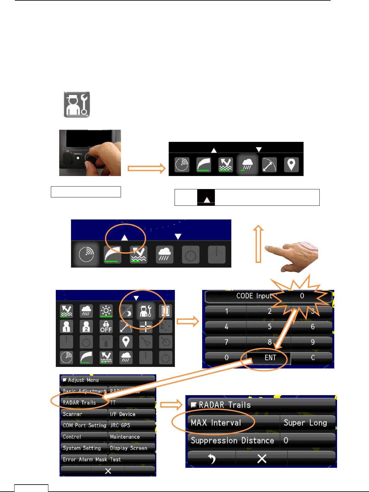
5-5 TRAIL (DISPLAY THE WAKE BEHIND THE SHIP)
(The heading signal and GPS signal is necessary.)
Under operating the radar and during cruise, adjust the wakes length behind the target.
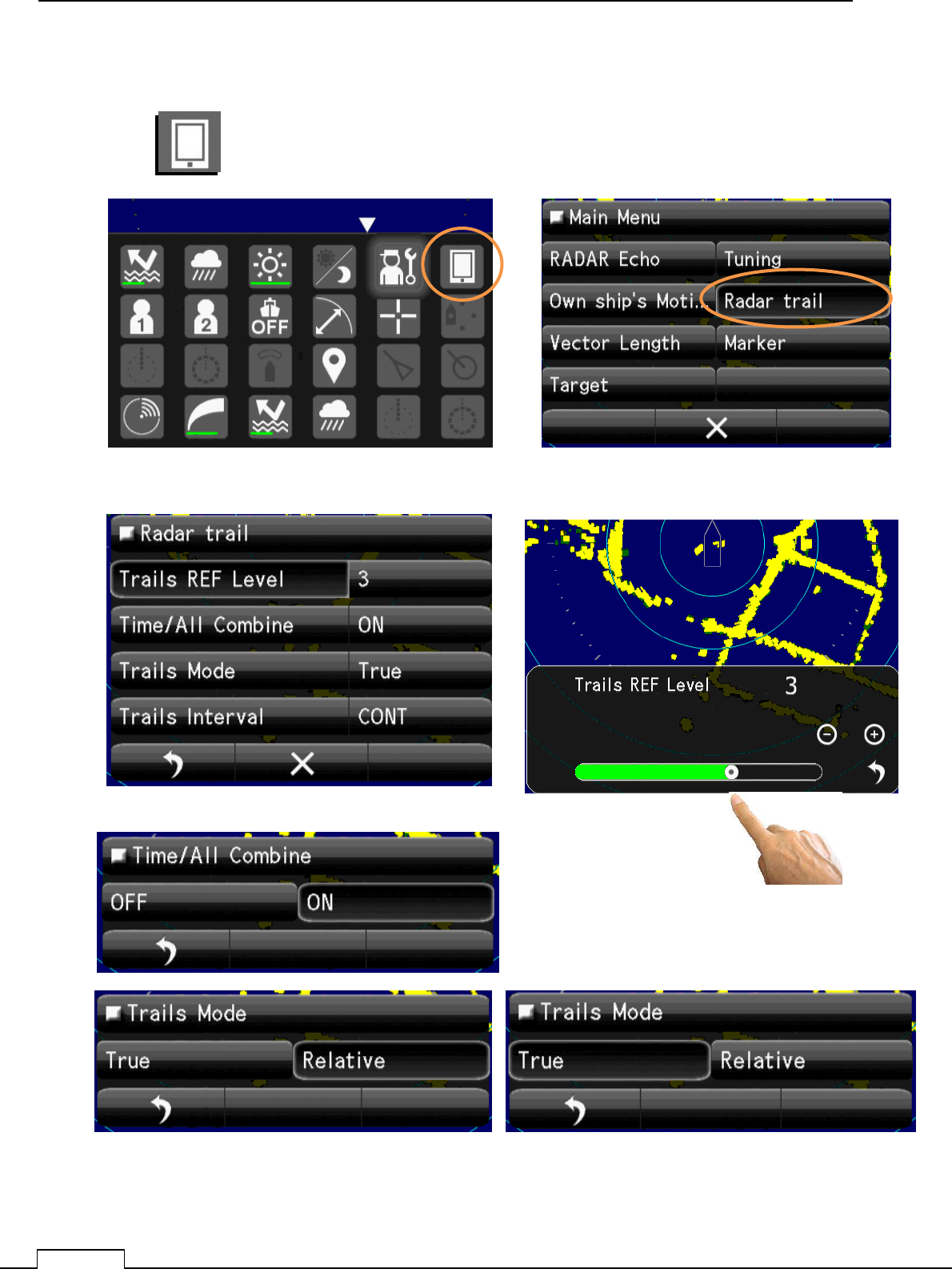
5-5-1 Selection of trail length.
When the Radar power is not on,
Press PWR/CLR button and Power ON.
Turn the Rotary knob and a ribbon icon is found on the lower right screen.
Push Rotary knob Tap “ “ or Flick screen towards upside.
Chapter 5 USEFUL FUNCTIONS
67
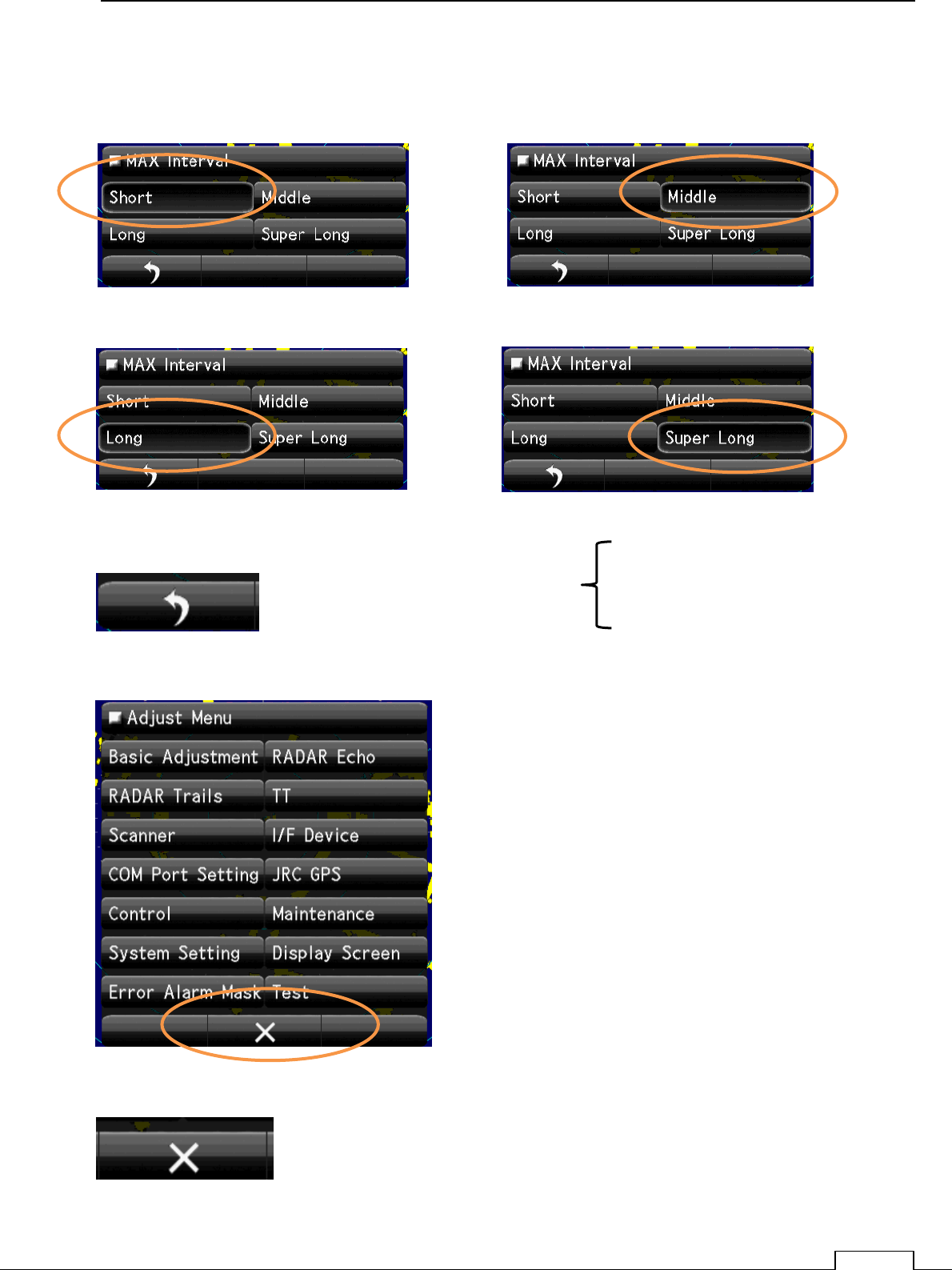
Select Trail length.
Trails: Short Trails: Middle
Trails: Long Trails: Super Long
Trails time Short
Middle
Long
Super Long
Return to Adjust Menu.
Quit Adjust Menu
Chapter 5 USEFUL FUNCTIONS
68
5-5-2 Select Radar Trail Mode
Chapter 5 USEFUL FUNCTIONS
69
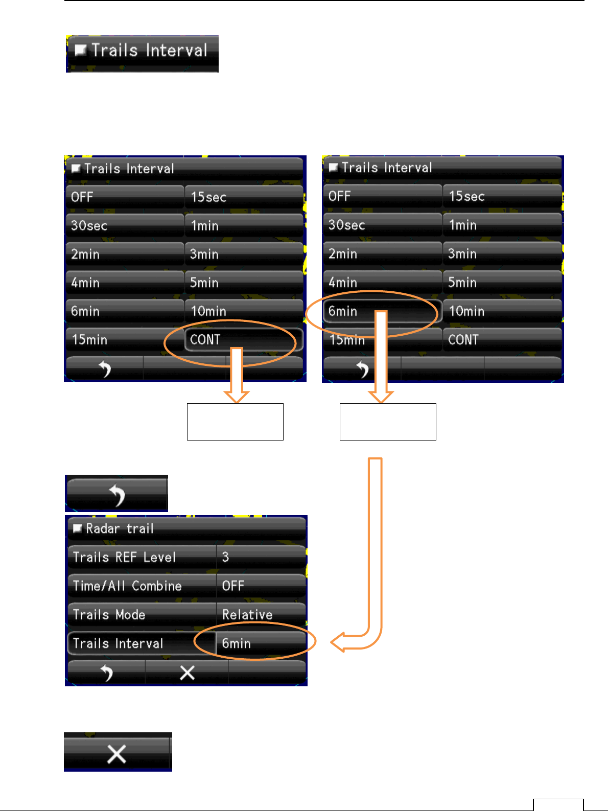
Select Trails Interval.
Example.
Return
Continuous trail 6minutes trail
Quit menu.
Chapter 5 USEFUL FUNCTIONS
70
5-6 AIS (AUTOMATIC SHIP IDENTIFICATION SYSTEM)
ACQUIRE THE ANOTHER SHIP INFORMATIONS
NOTES : To display AIS information, it’s necessary to connect AIS signal, GPS signal
and GYRO signal.
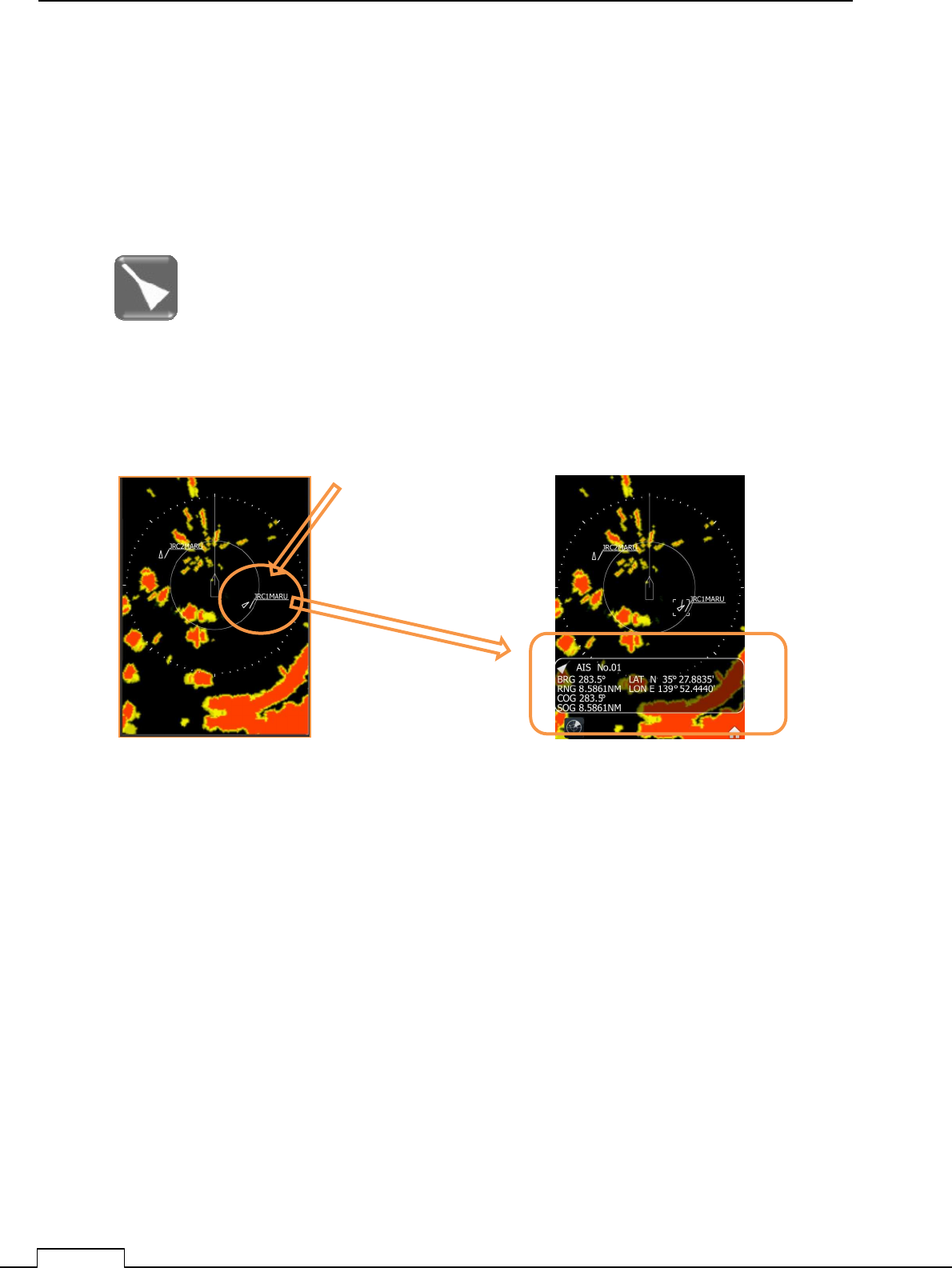
AIS position signal which place is included in display area, displays automatically.
Tap the AIS symbol, then display detail data information down side of screen.
Tap which you want to get
more information.
The tapped AIS information is displayed.
Bearing and Range is the position which ship is observed from own ship.
Course and speed is the target speed and true course.
Position is measured by the ship’s GPS data.
To release target detail data, use long tap.(keep press icon).
If Tap no AIS symbol surface place, Cursor icon will appear instead.
Again tap of icon on AIS symbol, display AIS again.
No action time more than 5Seconds, close information dialog automatically.

Chapter 5 USEFUL FUNCTIONS
71
BRG : Target BEARING from own ship direction. AIS No.01 ‘s DIRECTION 238.5degree.
RNG : Target RANGE from own ship position. AIS No.01 ‘s RANGE 8.5861nm.
COG :The sip’s Course of ground AIS No.01 ‘s COURSE(from north) 238.5degree.
SOG : The sip’s Speed of ground AIS No.01 ‘s Speed(from ground) 8.5826kn.
LAT : The sip’s POSITION Latitude AIS No.01 ‘s Latitude 35° 27.8835′.
N: Northern Hemisphere. S: Southern Hemisphere.
LON : The sip’s POSITION Longitude AIS No.01 ‘s Longitude 139° 52.4440′.
E:EAST W: WEST
Unit: Degree, Minute.
AIS Display example “
JRC1MARU”
Chapter 5 USEFUL FUNCTIONS
72
5-7 TT (TARGET TRACKING)
Notes : GPS (Speed)and the HEADING(Gyro) signal are also necessary.
Tracking the target function is effective to avoid collision accident.
The speed and direction of tracked target is automatically calculated, and if danger will be happen,
generate danger alarm sound and signal..
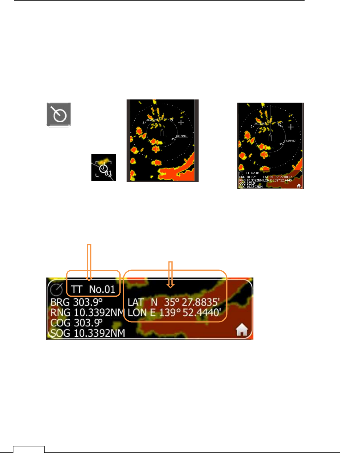
TT data display will be fadeout from the screen in 6 seconds after operation.
When tap the TT symbol place, changes in to TT function, another no symbol place change into
cross cursor display instead.
Long tap can release TT function.
Up to 10 targets are possible to tracking using TT function.
BRG : Target Bearing measured from own ship.(True mode, or Relative mode)
RNG : Target Range measured from own ship.
COG : Calculated target course. Calculated from own ship course and target ship course.
SOG : Calculated target speed. Calculated from own ship speed and target ship speed.
Tap the target which you want to track.
Up on the target, TT symbol will appear, and start tracking.
Tracked target is automatically note symbol and numbered.
Tap symbol, you can get the information of that TT.
The ship’s speed, course, longitude, latitude are
display downside of the screen..
Automatically assigned TT’s ID number.
Chapter 6 OPTIONAL FUNCTIONS
73
Chapter 6 OPTIONAL FUNCTIONS
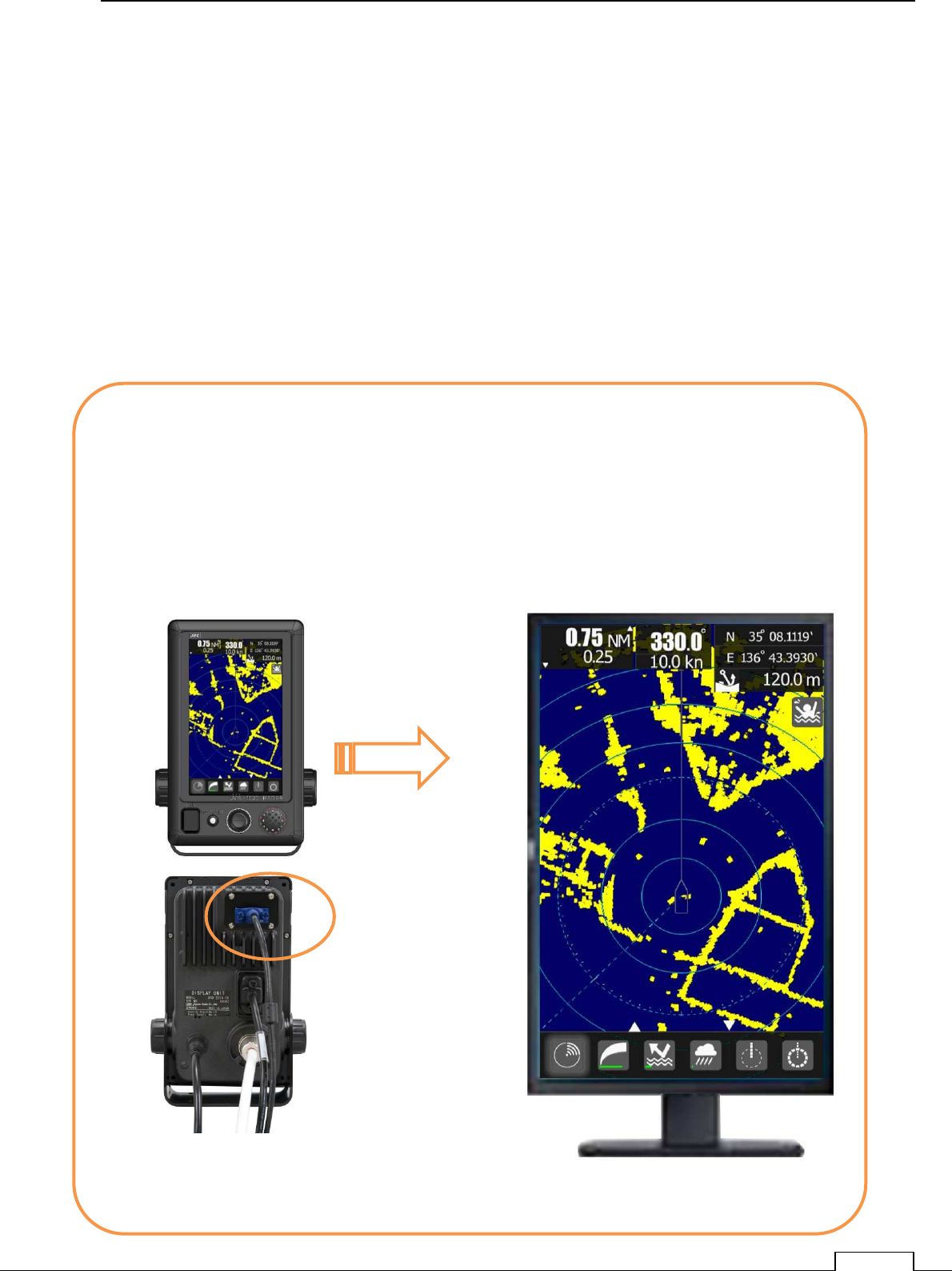
6-1 EXTERNAL MONITOR DISPLAY OUTPUT
Special interface: NQA-2447 (option)
Standard function can’t use the external monitor.
Optional kit “NQA-2447 “is line upped as this RADAR.
Additional Interface can possible to lead out the video signal to external monitor.
Additional external port is “D “sub 15pin connector output.
Display pixels are 800x480 dots (WVGA)
From external monitor, any control is impossible for operation.
External monitor’s power supply must be supplied, and Brilliance control is stand alone.
Cautions: Radar display is drawn in PPI.(PPI: Plan Position Indicator)
Original Range, Bearing signal are converted to X,Y memory plane.
Range is proportion to time (light speed)
Radar picture is required so correct circle.
In case of External monitor, sometime cannot describe so collect circle.
Included NQA-2447
WVGA VIDEO OUTPUT
External monitor display
(800x480 WVGA)
Connect Video cable.

Chapter 6 OPTIONAL FUNCTIONS
74
6-2 NMEA CABLE (OPTIONAL PURCHASE)
Option name: 7ZCRD1689
AIS, GPS, GYRO, LOG etc.: It is a cable which need for aid for navigation.
The data are received by IEC61162-1 / 2 (considerable).
The input signal (three-port GPS/HDG/AIS)
Navigation system interfaces, such as GPS
IEC61162-1 / 2 (considerable) Priority of data :
L/L: GGA>RMC>RMA>GNS>GLL
SOG/COG: RMC>RMA>VTG
Log speed: VBW>VHW
HEADING: THS>HDT>HDG>HDM
DEPTH: DPT>DBT
WATER TEMP: MTW
ROT: ROT
RUDDER: RSA
AIS: VDM,VDO,ALR
WIND: MWV>VWT,VWR
Bearing signal JRC-NSK format (JLR-10/20/30)
IEC61162-1/2(considerable)
4800bps/38400bps:THS>HDT>HDG>HDM
Speed signal IEC61162 4800 bps :VBW, VHW
Telecommunications standard NMEA0183 / 61162 to 1EC1 conformity
Communications protocol 4800 bps, start 1bit, data 8bit, stop 1bit,
With no parity
Input sentence NMEA0183:V1,5: GGA/ GLL/ RMC
V2,O: GGA/G LL/ RMC/ZDA
V2,3 : GGA/GLL/RMC/GNS/ZDA
(Talker= "G P" etc.)
Information classification about a ship -- the time entry; -- GGA/G NS/G LL/RMC
Day entry: ZDA/RMC
Time entry of equipment: ZDA/GGA/GNS/GLL/RMC

Chapter 6 OPTIONAL FUNCTIONS
75
6-3 RECTIFIER UNIT
Input Power supply voltage allowance is between DC10.8 to 31.2V (DC12-24V-10%+30%).
Power dissipation power is about 50W.
When ship’s DC battery power supply is not enough to this radar, use the rectifier unit.
AC /DC power converter unit name is NBD-865.
NBD-865 :
Input voltage AC100/220V
Output DC24V

Chapter
7
INITIAL SETTING
76
Chapter 7 INITIAL SETTING
7-1 INITIAL SETTING MENU
Before using the radar, try to do the most effective setup first.
Since almost all setting details are memorized inner memory, it is used as default data.
Various setup items as follows.
①
①①
①The adjust items which must done first.
Language setting
②
②②
②The adjust items which are possible to set later.
Tuning
Range
Scanner height
Communication port setting
GPS, AIS, GYORO, LOG
When unnecessary alarm is generated, set alarm mask setting and stop alarm.
Some item are not necessary to setup for start.( factory setting: default data are effective)
7-1-1 RECOMMEND SETTING BEFORE INITIAL SETTING
Language setup
7-1-2 NECESSARY SETTING BEFORE USE
Tuning control
Bearing adjustment
Range adjustment
Antenna height
7-1-3 ALREADY SETTED-UP IN FACTORY
, AND NOT NECESSARY TO SET-UP BEFORE USE
Alignment peak level adjustment
Chapter 7 INITIAL SETTING
77
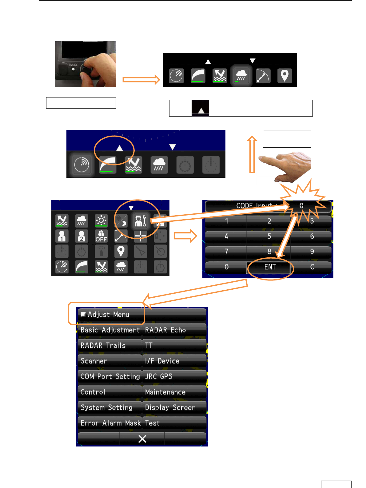
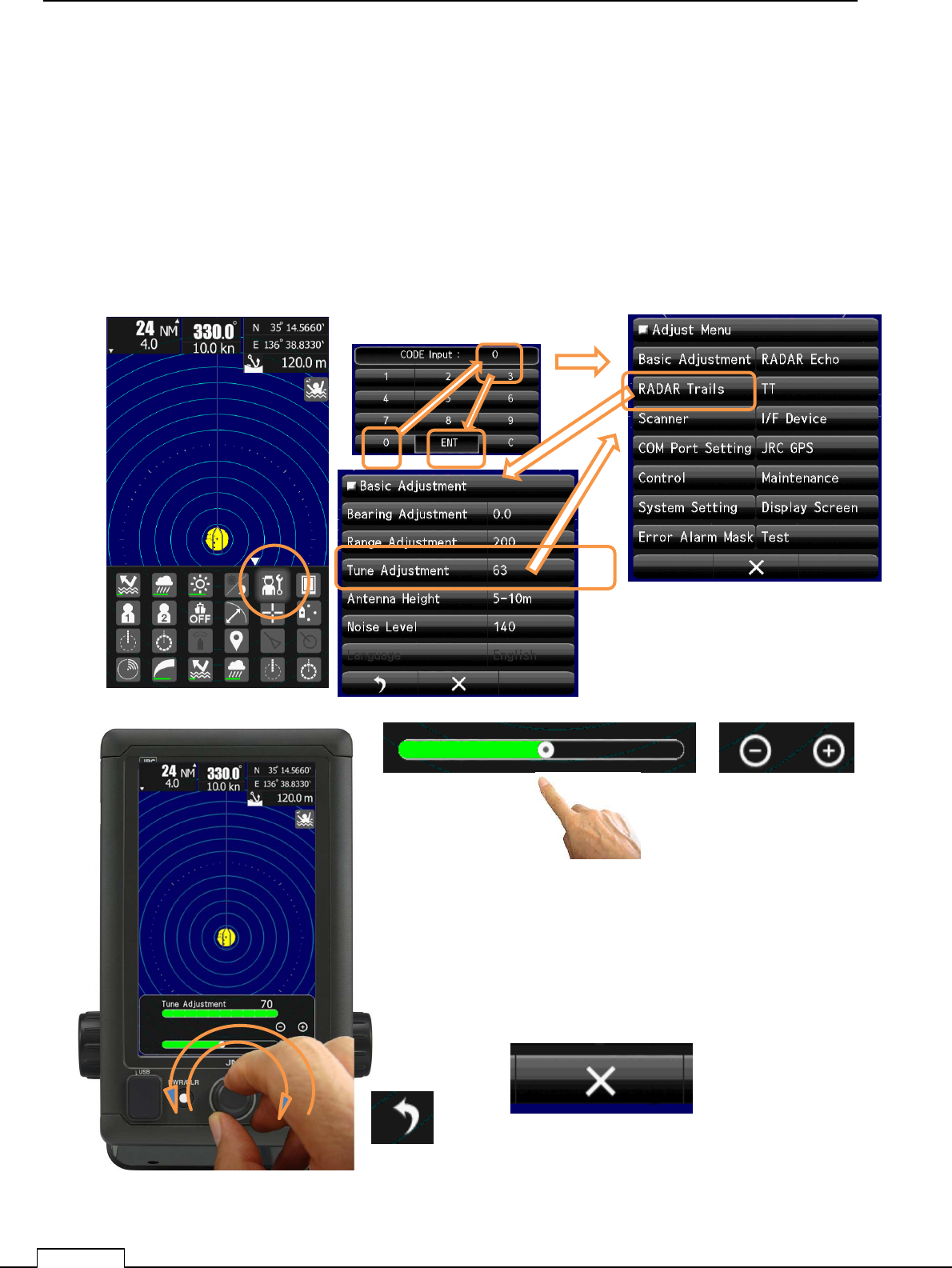
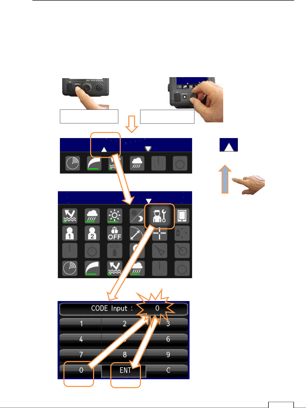
Push PWR/CLR button and power on.
Turn the Rotary knob, or tap downside icon, and appear the small menu.
Confirm “0” input and tap ENT.
Push Rotary knob Tap “ “ or Flick screen towards upside.
Flick upside
Chapter
7
INITIAL SETTING
78
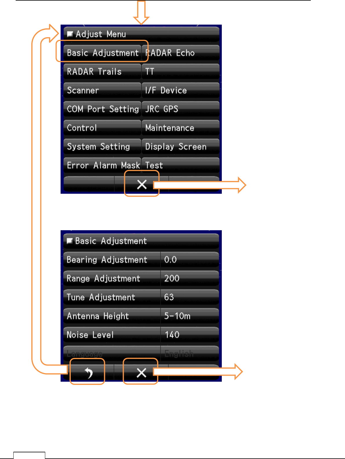
Select Basic adjustment.
In order to make it operate as a actual radar, minimum initial setting (basic adjustment) is
necessary.
Any sequence of adjustment is possible.
Please carry out tuning control and appear the radar echo on screen.
Tap Basic Adjustment
Set Bearing
Set Range
Set Tuning
Set Scanner Hight
Set Noise Level
Set Language
These Basic Adjustments are performed on TX.
Please adjust every item, observing the radar echo.
Quit to service menu
Quit to service menu
Chapter 7 INITIAL SETTING
79
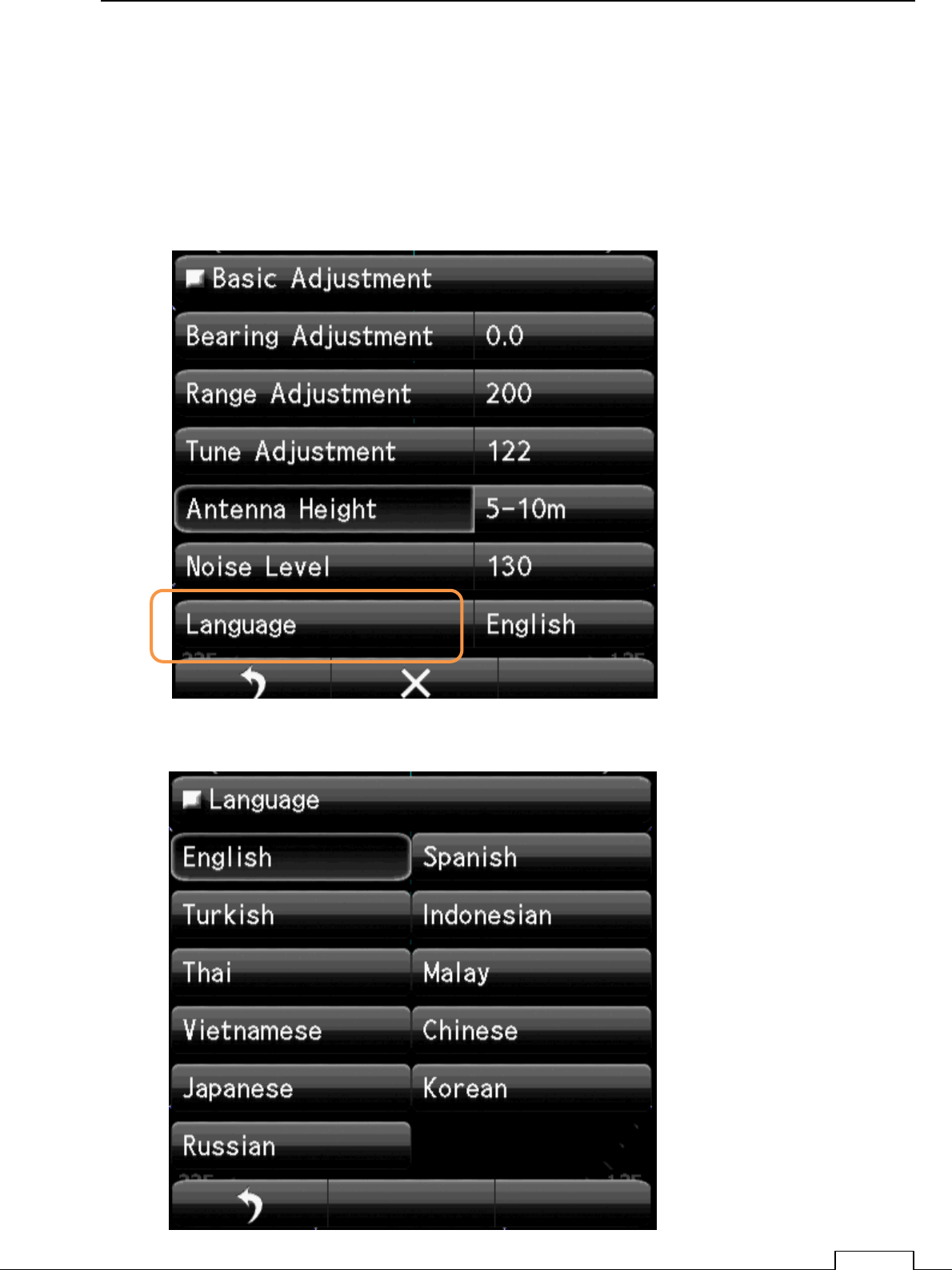
7-2 LANGUAGE SELECTION
The languages which can selectable are shown from menu.
Procedure
(1) Set Basic Adjustment as previous page.
(2) Select. Language item.
.
And select your Language.
Chapter
7
INITIAL SETTING
80
7-3 TUNING ADJUSTMENT
Tuning is necessary in order to keep high performance.
This function is adjustment of the Receiver to Magnetron frequency, and to get maximum radar sensitivity.
Procedure
(1) Set TX(radar transmission).
Select more longer range which can observe target.
For example, 12NM or 24NM.
Adjust GAIN, RAIN, and SEA so as to observe more long range target.
Return to Menu
Return to Main screen.
Turn Rotary knob or flick green belt or tap + - ,checking radar
Chapter 7 INITIAL SETTING
81
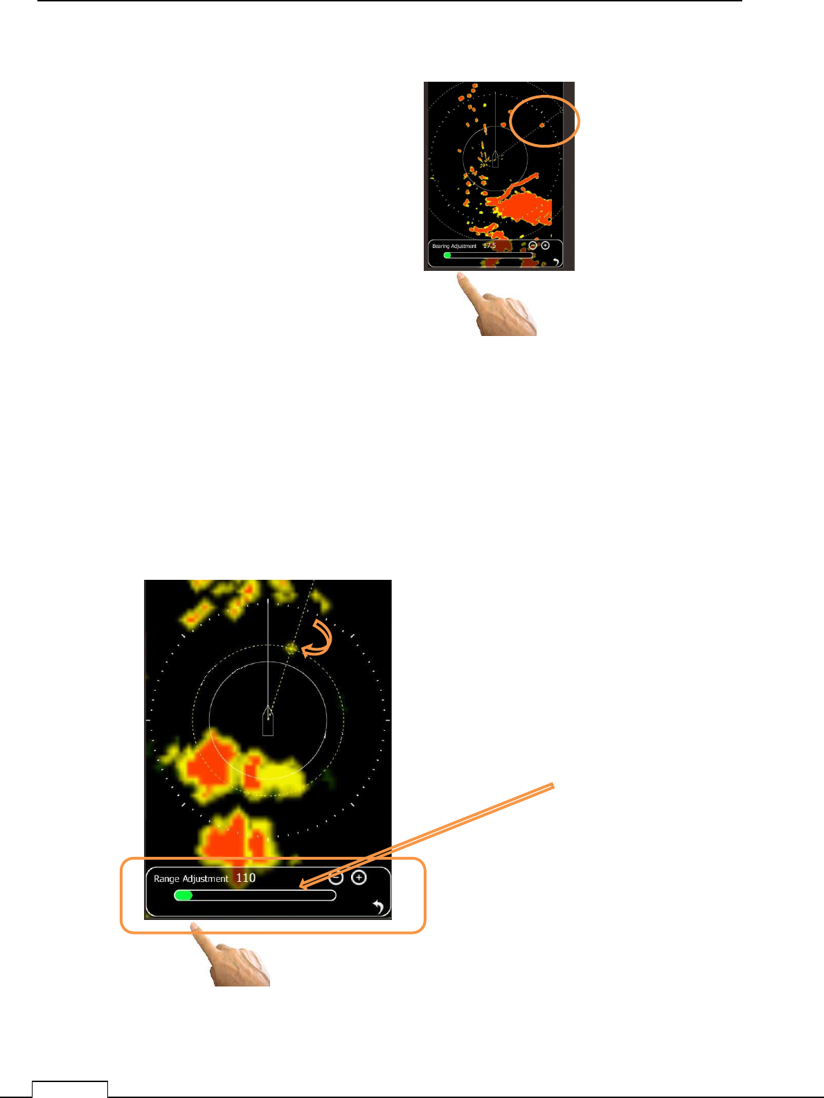
7-4 BEARING ADJUSTMENT
Adjust so that the heading marker (SHM) may align with the actual direction of a bow.
(Offset correction at the time of scanner installation)
Adjust the radar echo angle to the target angle which can observe by eye from bow.
Target viewing angle is view angle from scanner position, not display position.
So decrease error, select the more father target as long as possible.
This is the way of using EBL.
Procedure
(1) Set radar TX.
(2) Adjust GAIN, RAIN, and SEA and find a known target on the screen.
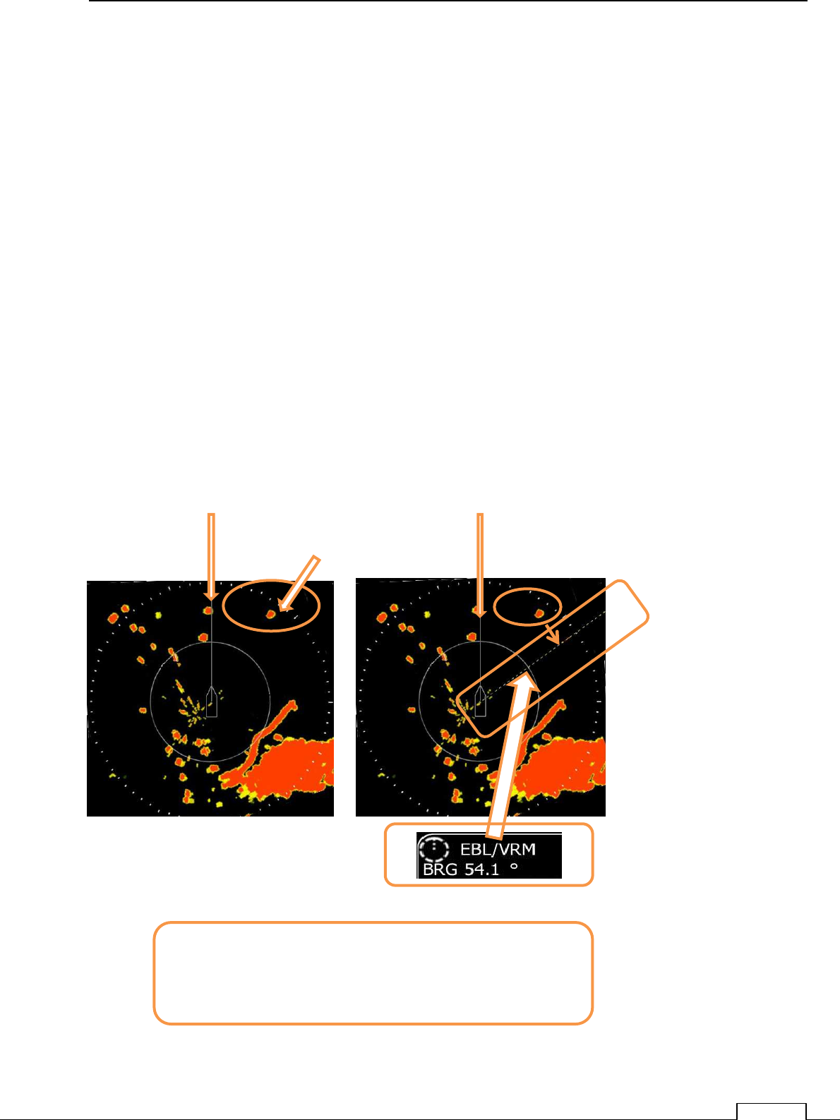
In the case of the following figure, the target at the upper right of screen is a known
target, and the direction from the bow(SHM).
In the case of the target which is 54 degrees as measured by viewing angle.
Set up EBL to 54 degrees and hold.
.
Next item must to do.
Turn the target echo until coincidence with EBL.
At that point is the off set point of Bearing Adjustment.
Press Rotary knob and fix data.
BOW
SHM (Ships Heading Line)
Select Target
Rotate target echo on the EBL
SHM
Chapter
7
INITIAL SETTING
82
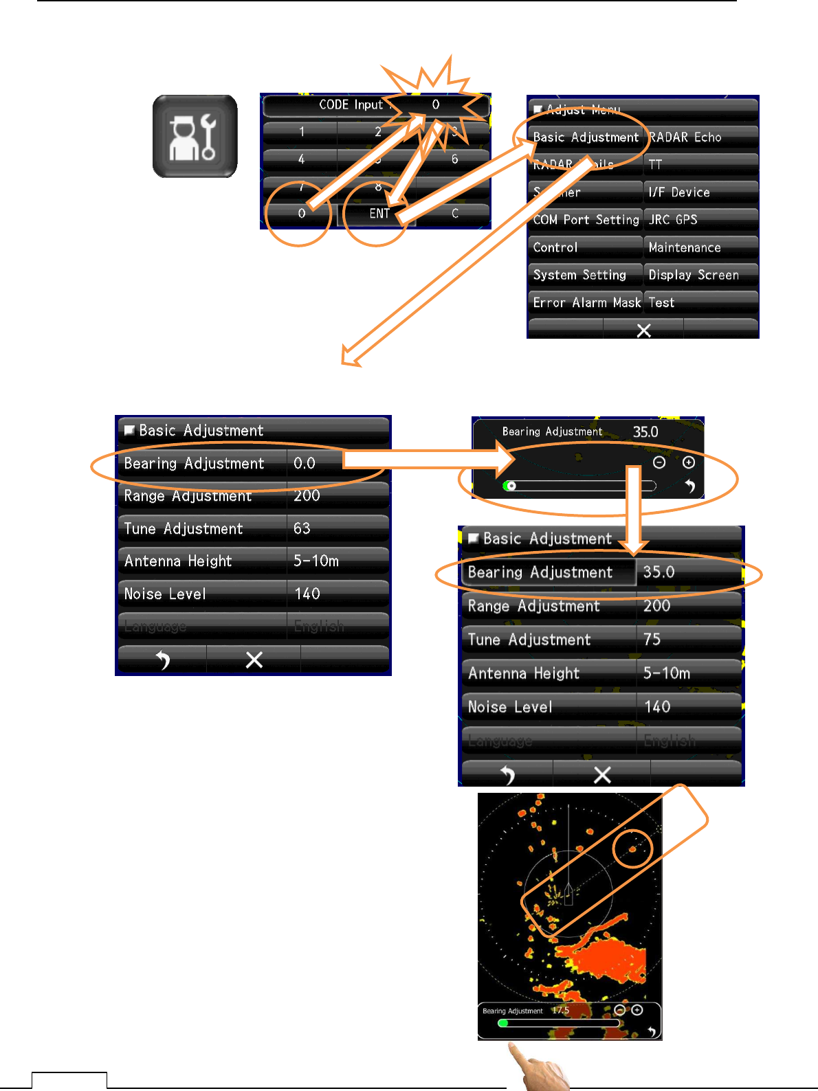
(3) Call service menu.
(4) Call Adjust Menu to Basic Adjustment and tap Bearing Adjust.
Echo and EBL meet with on the line is
correct offset angle.
Click Rotary knob and fix offset data.
(5) In this state, radar echo is possible to turn.
Downside of screen is displayed the offset
data (green belt line level).
Flick of green belt or tap of + - can change the
offset position.
Adjust the echo on the EBL.
Chapter 7 INITIAL SETTING
83
7-5 RANGE ADJUSTMENT
Read out the target range is used by VRM.
This set up is coincident the target RANGE with VRM readout data.
Select the target which is already known by map or another way.
The target height is the same as radar scanner is better condition.
The target echo‘s collect range is edge of radar side.(near centering on screen).
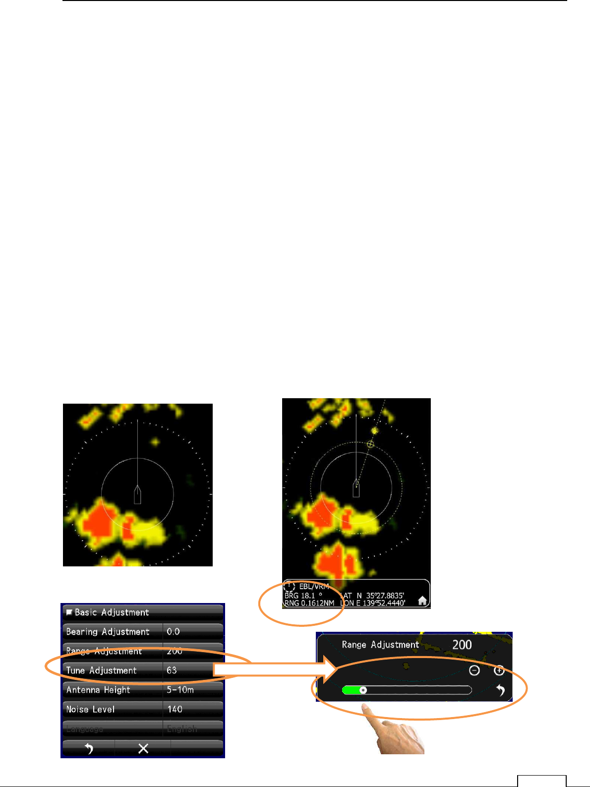
A distance unit is usually using “ NM”. (1nm= 1852m).
As an example Target which is distance of 300 m from own -ship,
300m x(1/1852m) =0.16198NM .
Procedure
(1) Set the radar transmit.
(2) Adjust GAIN, RAIN, and SEA and find a known target from screen.
The smaller target is easy to adjust range.
The nearest point of the target must be set as an actual distance.
Since the target length of radius direction proportion to the pulse length, set target’s front side by
VRM.
Reading of VRM is set as an actual distance.
Chapter
7
INITIAL SETTING
84
(3) Adjust the RANGE.
(4) Range adjust will be possible to adjust.
Down side of screen green bar’s flick or + - tap can change the echo range.
Move the echo’s front end come onto the VRM line.
At this point shows the collect offset range.
Click the Rotary knob and finish the range initialize adjustment.
The target which actual range of 300m(0.162nm) is
measured by VRM as 0.162nm.
This offset data is memorized in nonvolatile memory.
For the first time setting is necessary.
Chapter 7 INITIAL SETTING
85
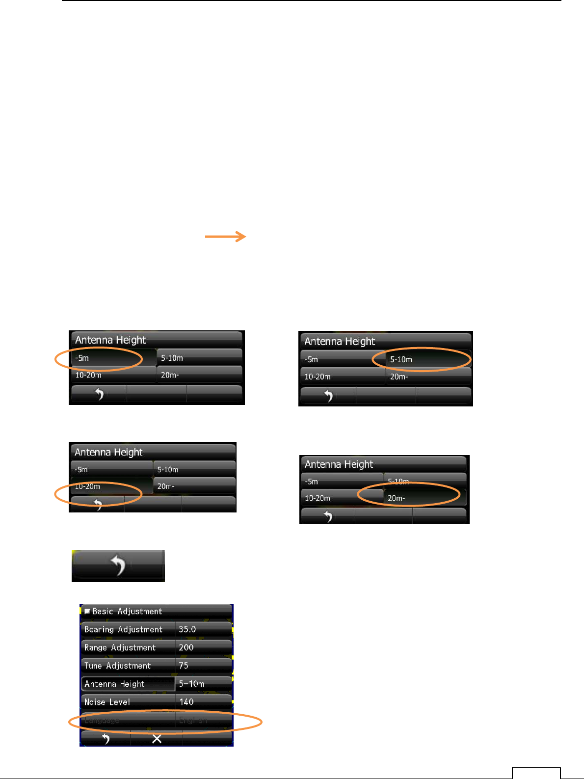
7-6 ANTENNA HEIGHT SET UP
Set up the antenna height.
This set up is related to sea clutter rejection control,
In near the range, Sea clutter level is proportion to the height of antenna position.
So optimum sea clutter rejection constant is selected according the height of antenna
Procedure
(1) Turn a Rotary knob and tap the ribbon.
(2) If an icon menu comes out, tap tool icon.
Select Basic Adjustment Antenna Height .
At selection menu, tap actual antenna height data.
Selected portion is reversed highlight.
Antenna height 5-m or less Antenna height From 5 m to 10 m
Antenna height 10 m to 20-m Antenna height More than 20 m
To fix the data is tap the right side return mark.
Confirm the menu if the selected value is set up.
Actual antenna height is set.
Expect the optimum control of sea clutter
rejection.

Chapter
7
INITIAL SETTING
86
7-7 ALREADY SETTED-UP ADJUSTMENT IN FACTORY
Please use on factory setting.
Adjustment is not always necessary.
Almost all adjustment is done in the factory, so necessary adjusting item is limited.
For example, it is not necessary items are follows.
7-8 Communication functions setup.
(Some case is necessary except can’t automatically receivable.)
8-3-6 Tune peak adjustment
8-3-7 Tune indicator level adjustment.
From after next section is the guide to set up aid for better performance functions.
Set up any time while use.
Chapter 7 INITIAL SETTING
87
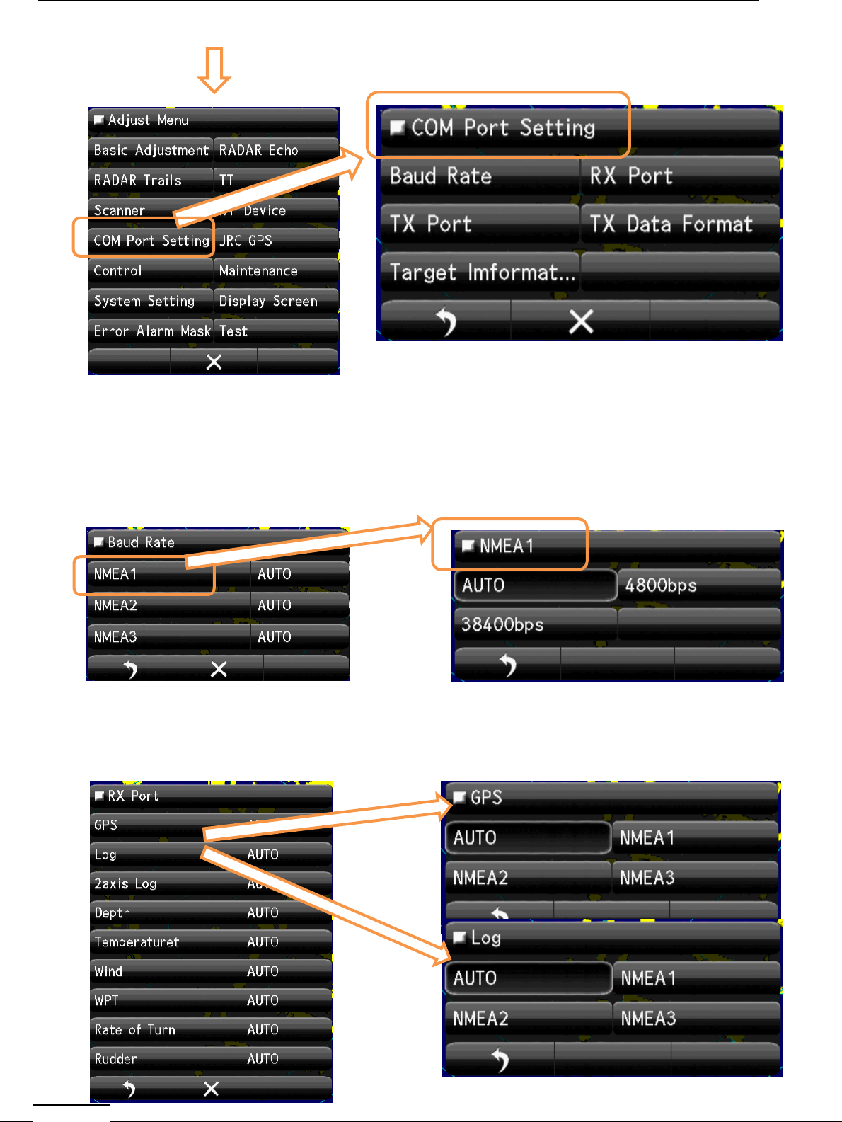
7-8 COMMUNICATION PORT SETUP
Set up the communication port to communicate external device.
Push PWR/CLR button and power on.
Turn the Rotary knob, or tap downside icon, and appear the small menu.
Tap service icon.
Tap icon
Or flick toward upside the screen.
Push PWR/CLR Push Rotary knob
Chapter
7
INITIAL SETTING
88
Open com port setting menu.
7-8-1 BAUD RATE
Data speed setting of communication.
Auto position: Selected automatically by receiving signal.
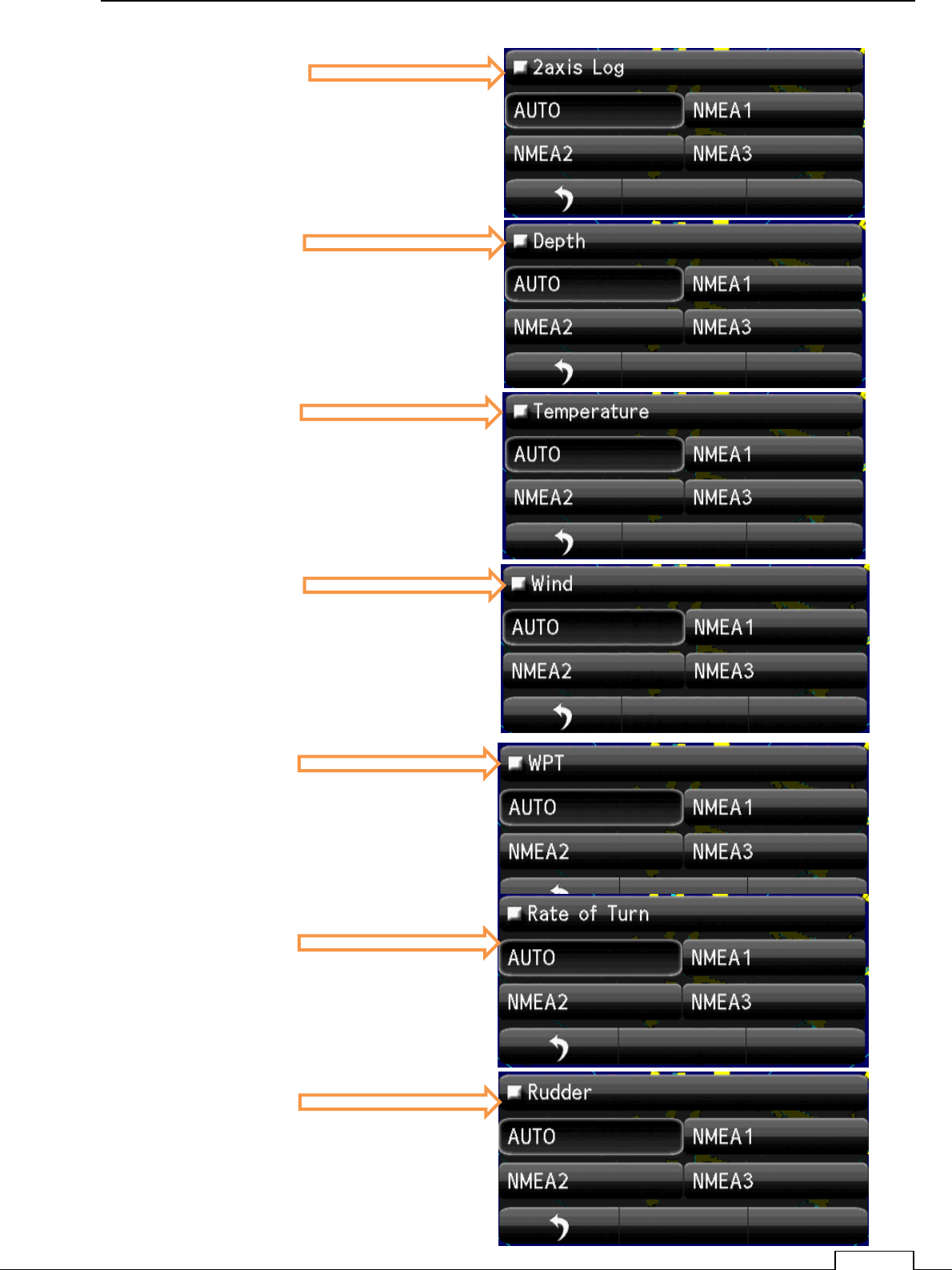
7-8-2 RX PORT
Receiving port selection, which kind of signal should receive from which terminal.
Chapter 7 INITIAL SETTING
89
2axis Log
Depth
Temperature
Wind
WPT
Rate of Turn
Rudder
Chapter
7
INITIAL SETTING
90
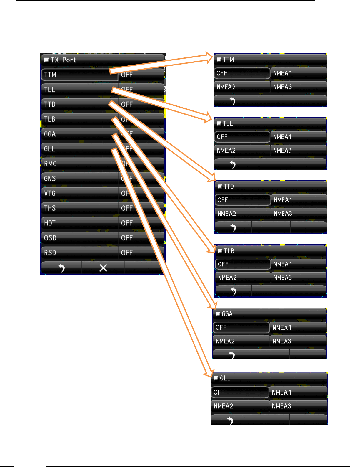
7-8-3 TX PORT
Transmitting port selection, which kind of signal should be send from which terminal.
Chapter 7 INITIAL SETTING
91
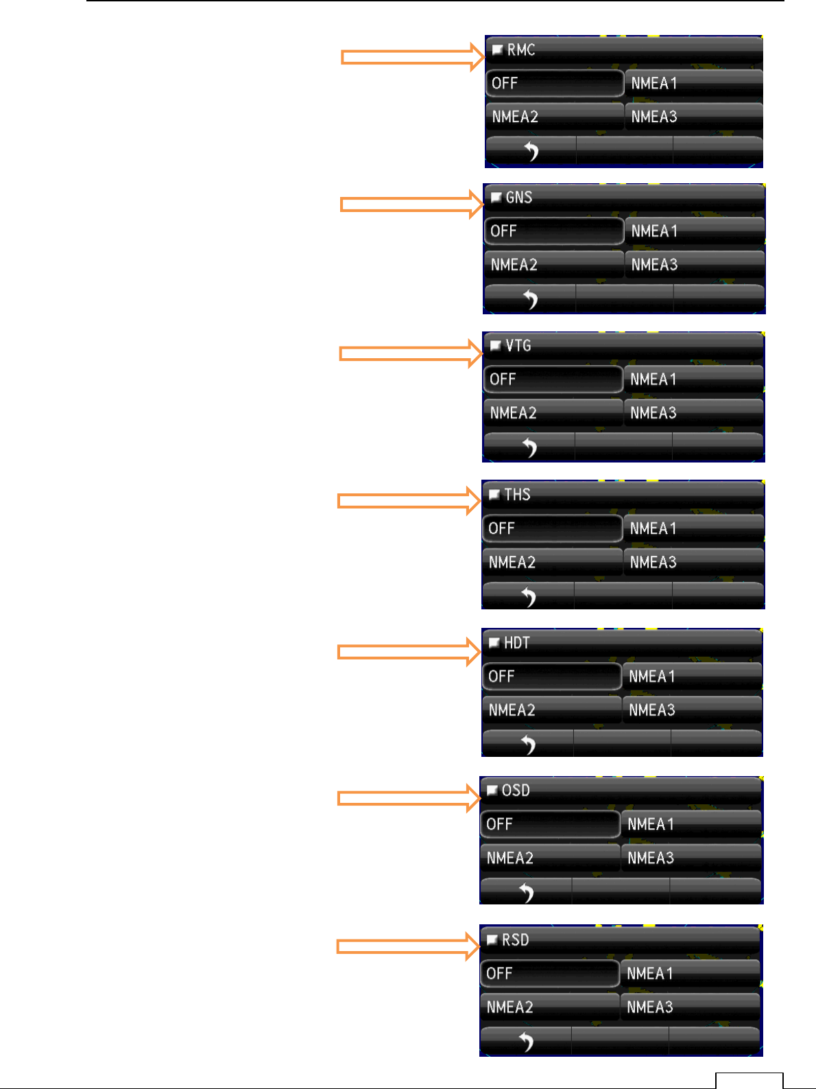
RMC
OSD
GNS
RSD
HDT
THS
VTG
Chapter
7
INITIAL SETTING
92
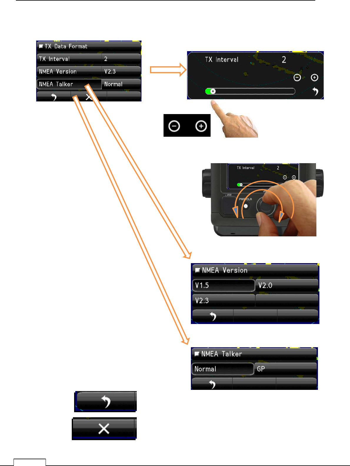
7-8-4 TX DATA FORMAT
Standards selection of transmitting data format
Turn Rotary knob or flick green belt or tap + - ,checking radar echo.
Set up the TX Interval..
Return to COM Port Setting.
Quit to Service menu.
Select NMEA Version.
Select NMEA Talker
Chapter 7 INITIAL SETTING
93
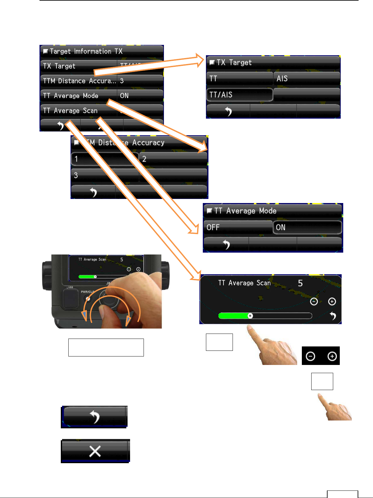
7-8-5 TARGET INFORMATION TX
When send target information, set up which information must be selected.
Return to COM Port Setting.
Quit to Service menu.
Turn Rotary knob or flick green belt or tap + - ,checking radar echo.
Set up the TT Average Scan.
Flick
Tap
Turn Rotary knob
Chapter
7
INITIAL SETTING
94
7-9 EXTERNAL INPUT SIGNAL SELECTION
For safe navigation, needs the correct navigational signals.
Own position, speed, course, gyro compass information etc. must be input and receive correctly..
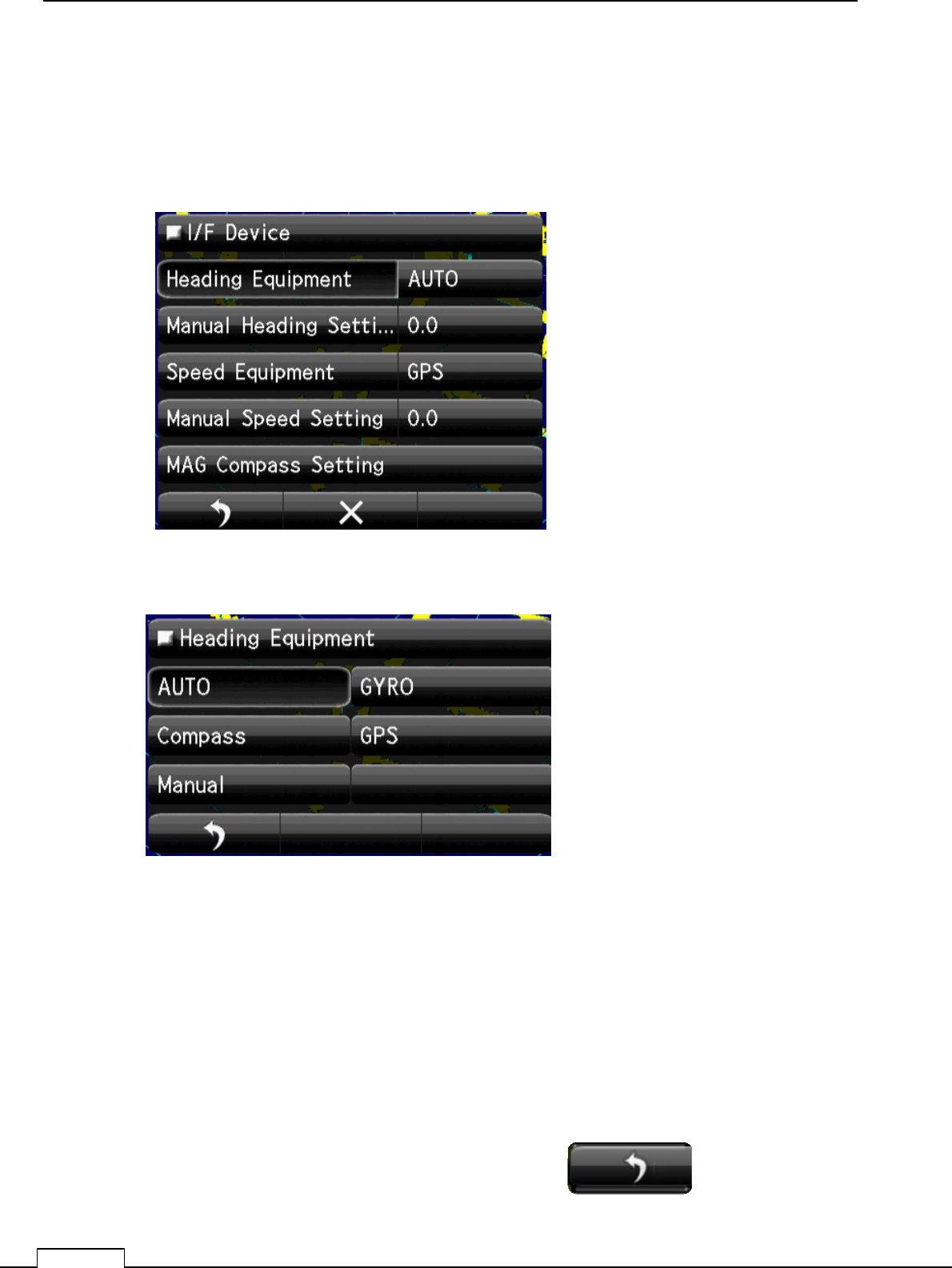
Select the heading, speed, device.
7-9-1 HEADING SIGNAL DEVICE SELECT
(Heading direction measured from the north.)
AUTO: Select the available equipment data which priority is high.
GYRO: Select the gyrocompass data.
Normally use this data, because of stability.
Compass: Select magnet compass data.
Not so stable, normally not use.
For TT function, can’t use.
GPS: Receive from GPS receiver, at slow speed, can’t output stable data.
For TT function, can’t use.
Manual: Manual setting only.
Not use for navigation.
Select Input device and tap return icon.
Return to the I/F Device menu.
Chapter 7 INITIAL SETTING
95
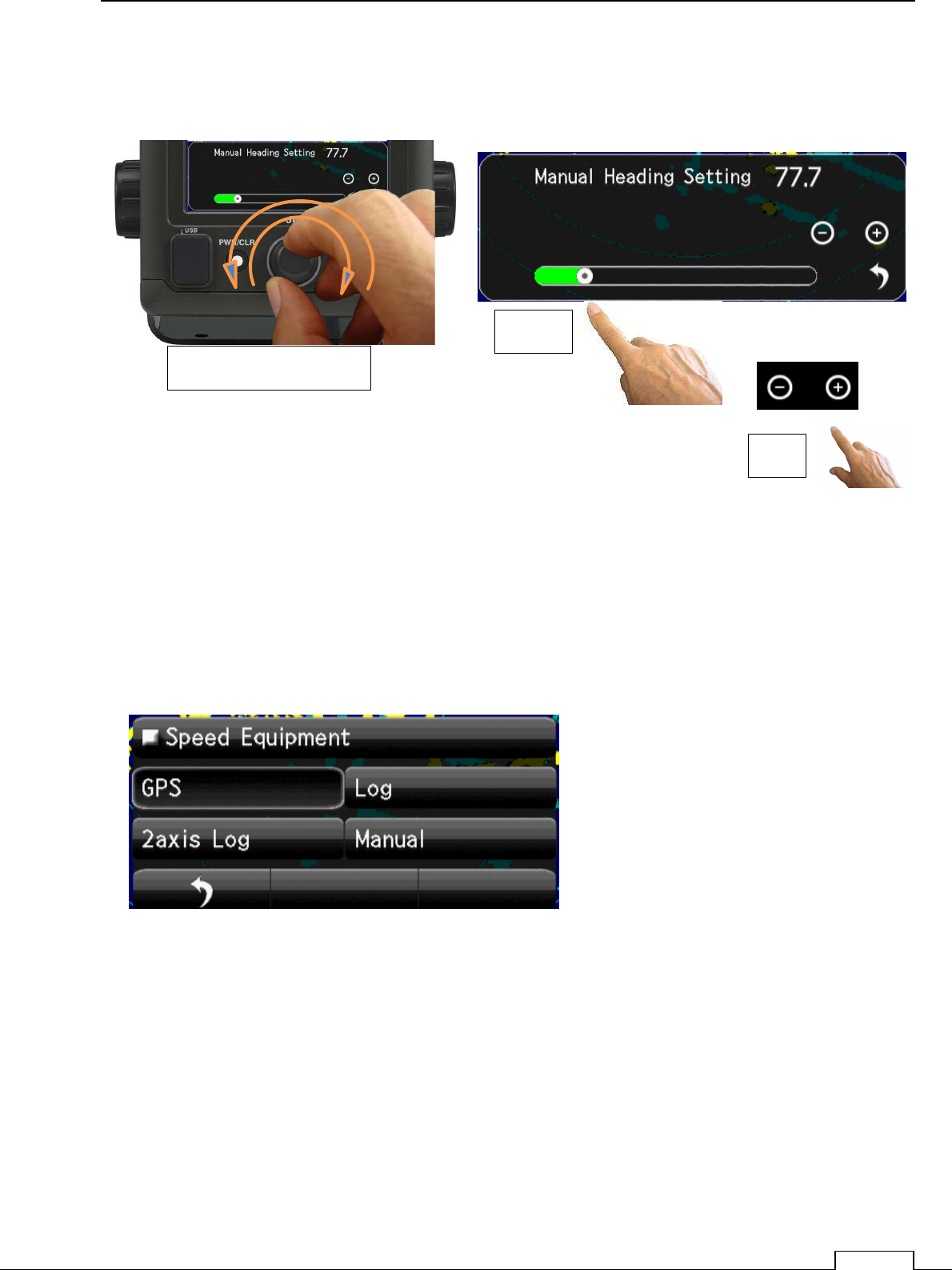
7-9-2 MANUAL HEADING INPUT
manual heading setup.
Manual Heading setting Bar appears in lower screen.
Flick the green bar and set.
Or tap +- is possible.
7-9-3 SPEED INPUT SELECTION
Hull speed information input selection.
GPS: Select GPS speed information.
Log: The LOG speed data.
2axis Log: The speed data of two axes (X-axis, Y-axis).
Manual: The manual input of the hull speed. (Usually, it does not use.)
When moving by simulator etc.
Turn Rotary knob or flick green belt or tap + - ,checking radar echo.
Set up the Manual Heading Input.
Flick.
Tap
Turn Rotary knob
Chapter
7
INITIAL SETTING
96
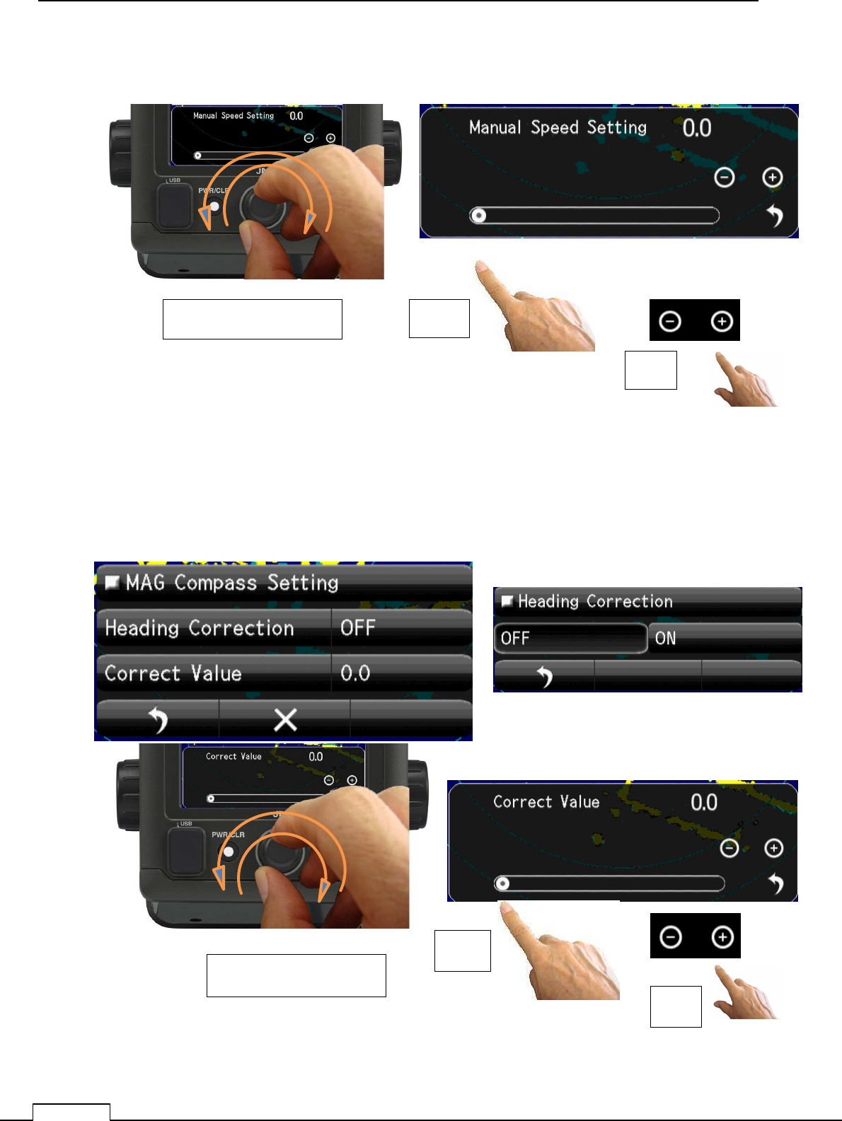
7-9-4 MANUAL SPEED INPUT
A speed input is possible by manual.
Manual Speed setting bar will appears in a screen.
Flick green bar, or it possible to set up by tap +- and click Rotary knob.
7-9-5 MAGNETIC COMPASS SETUP
Set magnet compass offset. (Data is not stable, usually it does not set up.)
Turn Rotary knob or flick green belt or tap + - ,checking radar echo.
Set up the Manual Heading Input.
Flick
Tap
Turn Rotary knob
Turn Rotary knob or flick green belt or tap + - ,checking radar echo.
Set up the Manual Heading Input.
Flick
Tap
Turn Rotary knob
Chapter 8 DETAIL RFORMANCE SETTING
97
Chapter 8 DETAIL PERFORMANCE SETTING
8-1 RADAR ECHO SETUP
Set up for appearance, more obvious target echo.
Since almost all setting details are memorized, and used as default data for the next time.
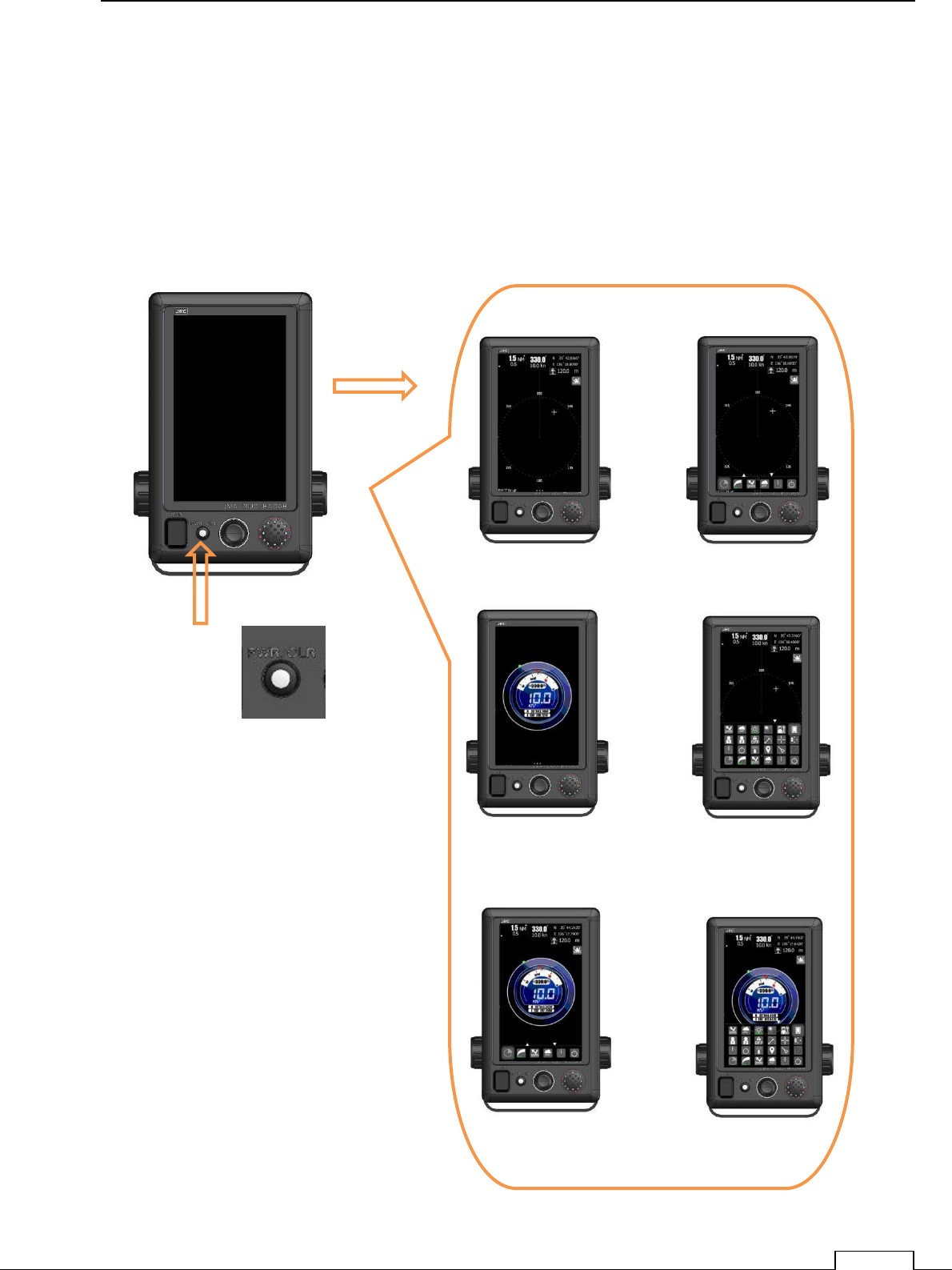
Turn on the power by push PWR/CLR.
Turn the Rotary knob and display the small icon group on the screen.
Push
PWR/CLR
button
Various ST-BY
screen.
Power ON
Chapter
8
DETAIL PERFORMANCE SE
TTING
98
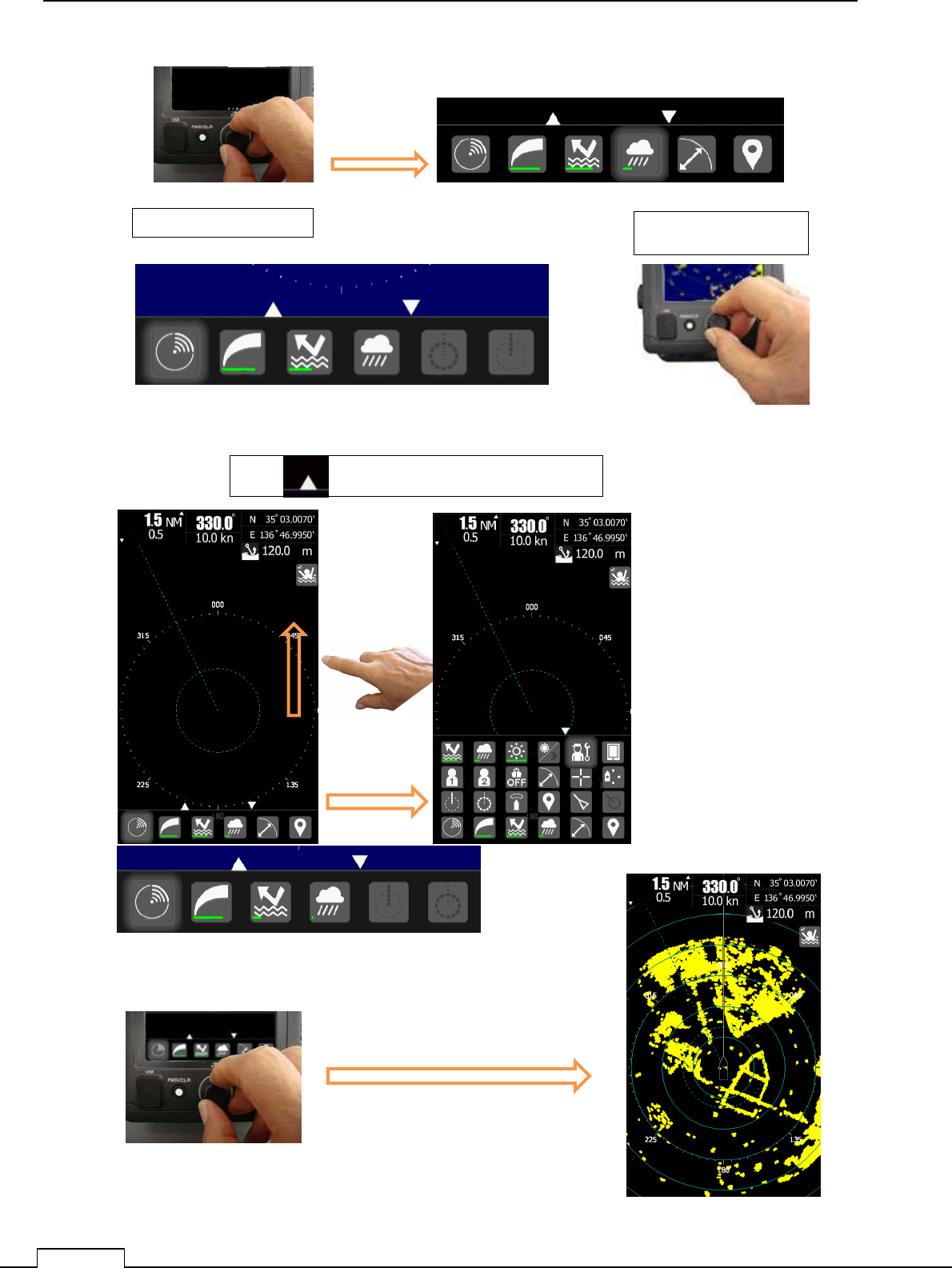
Or Push Rotary knob
Tap icon.
Push Rotary knob Push Rotary knob.
Tap “ “ or Flick screen towards upside.
Select TX-STBY icon, and push Rotary knob.
Push the Rotary knob, then Transmitting(TX) start
transmitting.
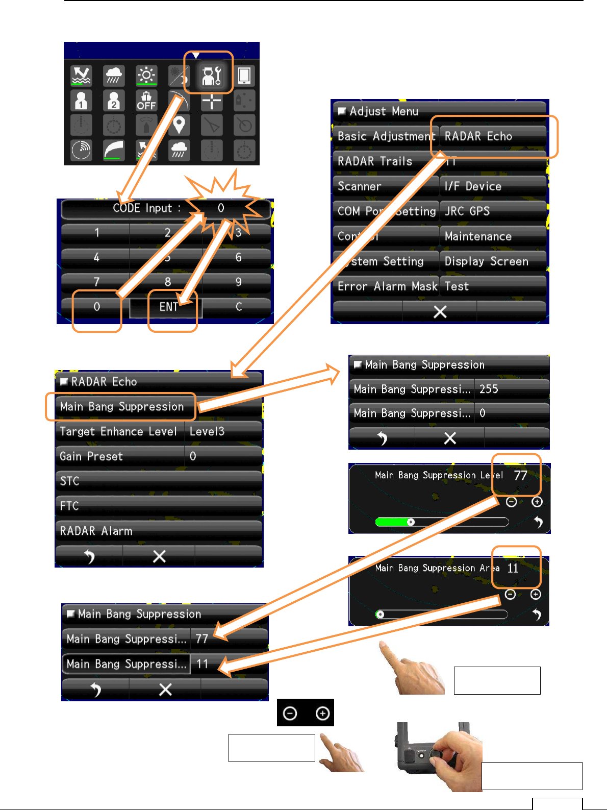
Chapter 8 DETAIL RFORMANCE SETTING
99
Flick green bar
Use Rotary knob.
Tap “ – “ “+”