Japan Radio Co NKE2044 MARINE RADAR User Manual 4
Japan Radio Co Ltd. MARINE RADAR 4
Contents
- 1. User Manual 1
- 2. User Manual 2
- 3. User Manual 3
- 4. User Manual 4
- 5. User Manual 5
User Manual 4
Chapter
8
DETAIL PERFORMANCE SE
TTING
100
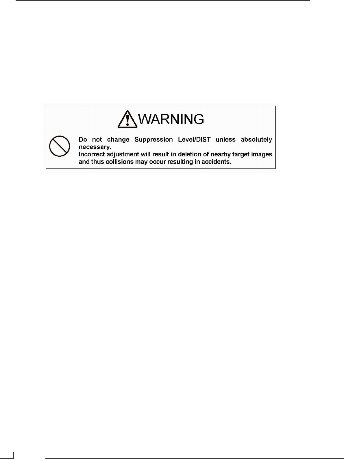
8-1-1 MAIN BANG SUPPRESSION
(Usually, doesn’t need set up. adjust if necessary)
This adjustment is decrease the transmitted signal which appears as a circular echo around the
center.
Adjustment is done so as to main bang is observe slightly seen.
Excess adjusting is danger for nearest small target observation.
If the main bang is not so big, use as factory setting.
Chapter 8 DETAIL RFORMANCE SETTING
101
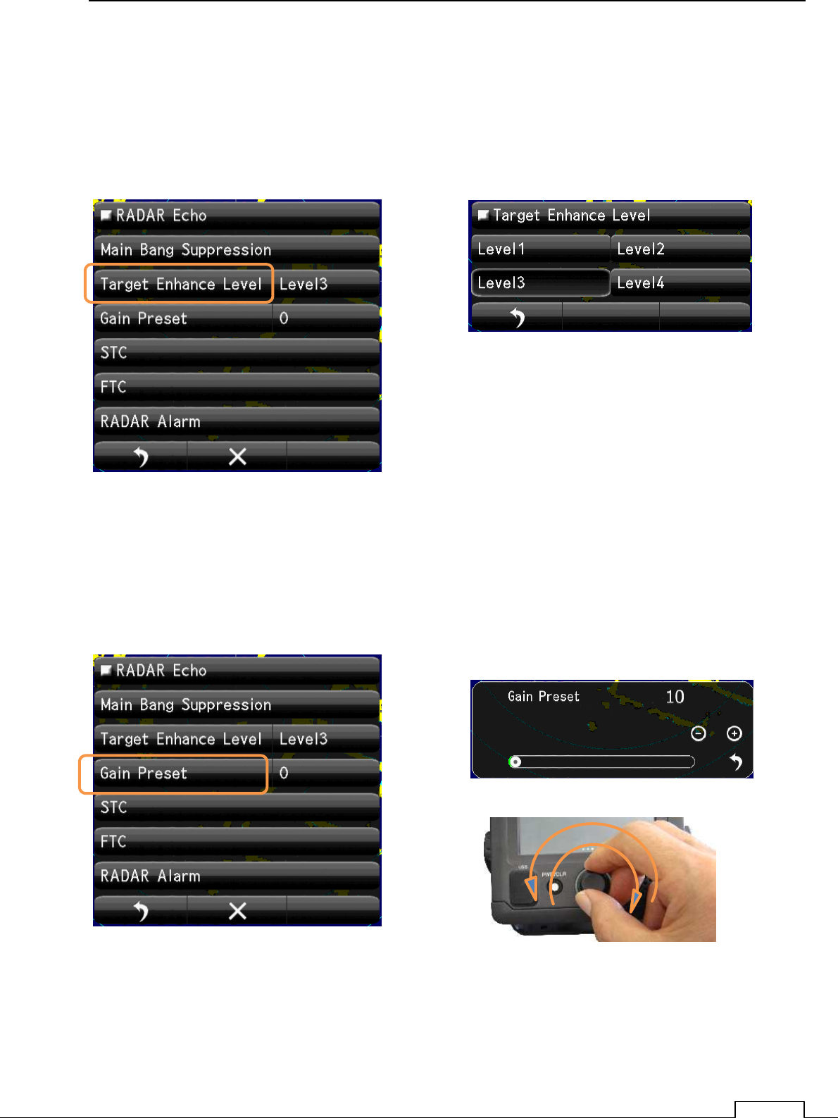
8-1-2 TARGET EXPANSION
Level setting.
The level which can be set up is level 1, the level 2, the level 3, and the level 4.
Expansion and the magnifying the observation target size..
Tap the “Level1, Level2, Level3, Level4“ icon.
8-1-3 GAIN LEVEL
(Important adjustment. Since adjusted in factory, adjustment is not necessary in the field.)
Chapter
8
DETAIL PERFORMANCE SE
TTING
102
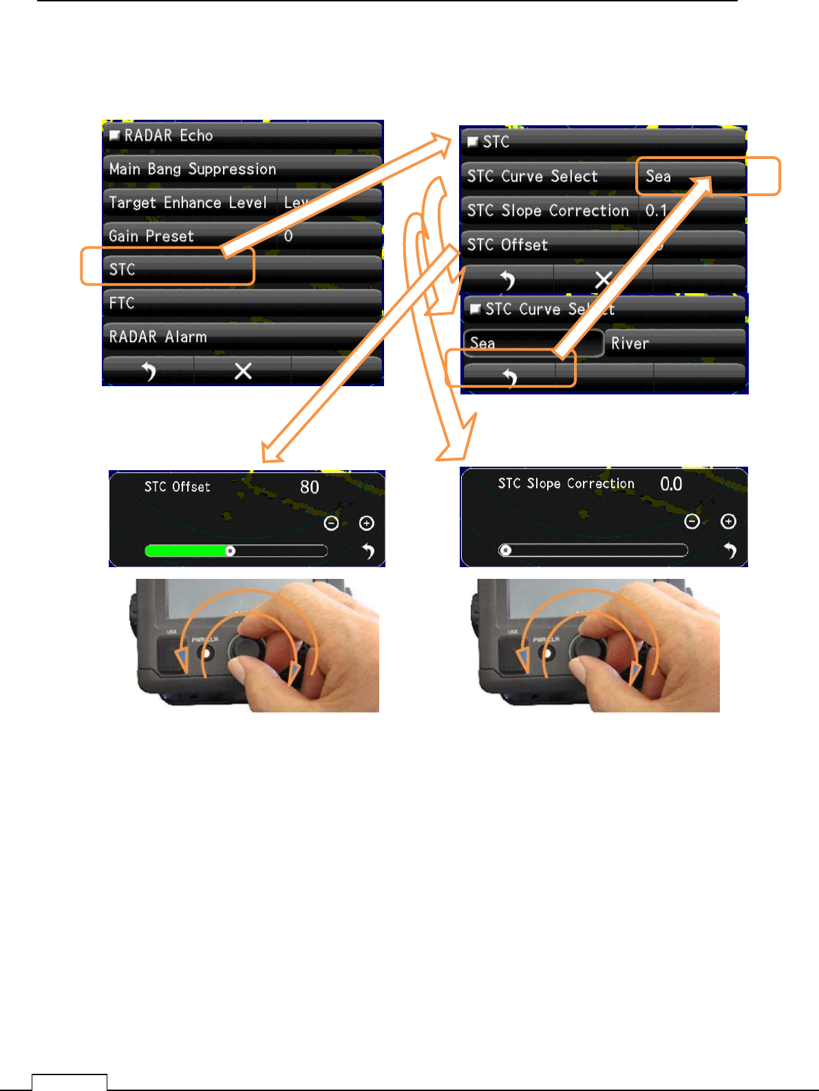
8-1-4 SEA CLUTTER LEVEL
(Important adjustment. Since adjusted in factory, adjustment is not necessary in the field.)
Chapter 8 DETAIL RFORMANCE SETTING
103
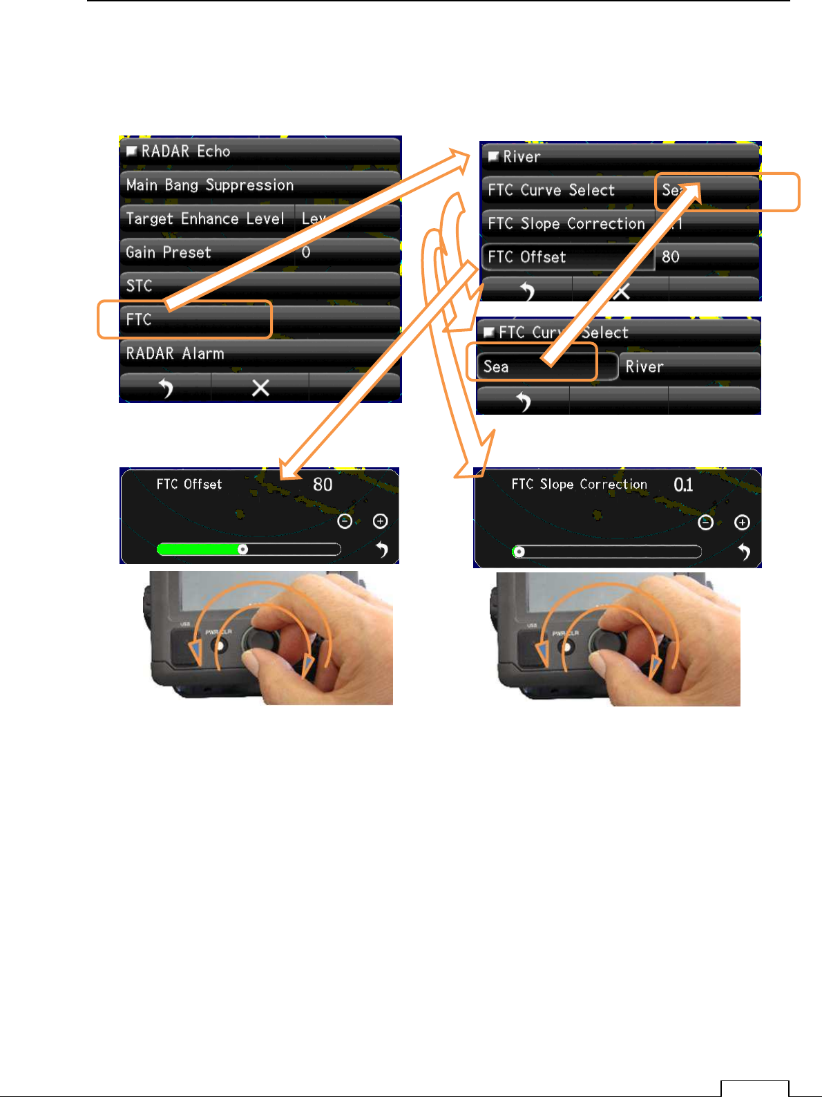
8-1-5 RAIN AND SNOW CLUTTER LEVEL
(Important adjustment. Since adjusted in factory, adjustment is not necessary in the field.)
Chapter
8
DETAIL PERFORMANCE SE
TTING
104
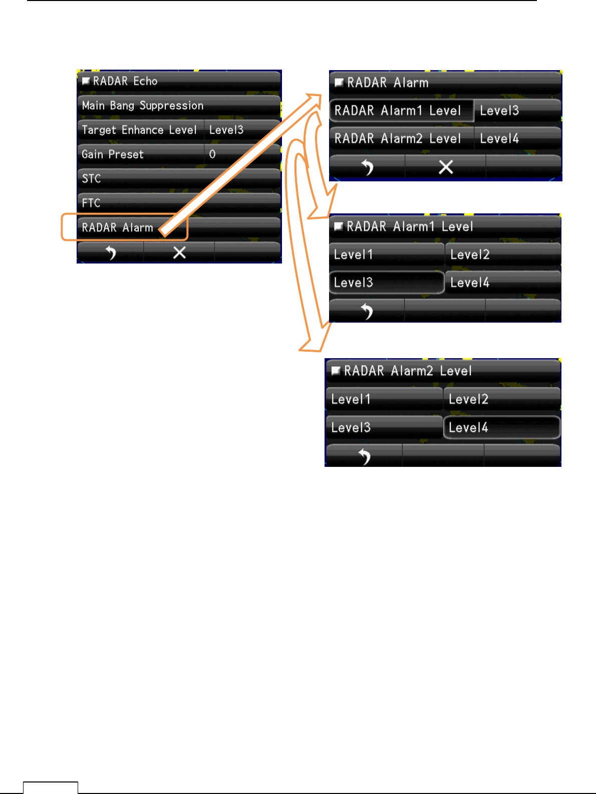
8-1-6 RADAR Alarm LEVEL
Set up Alarm 1 Level
Set up Alarm 2 Level
Chapter 8 DETAIL RFORMANCE SETTING
105
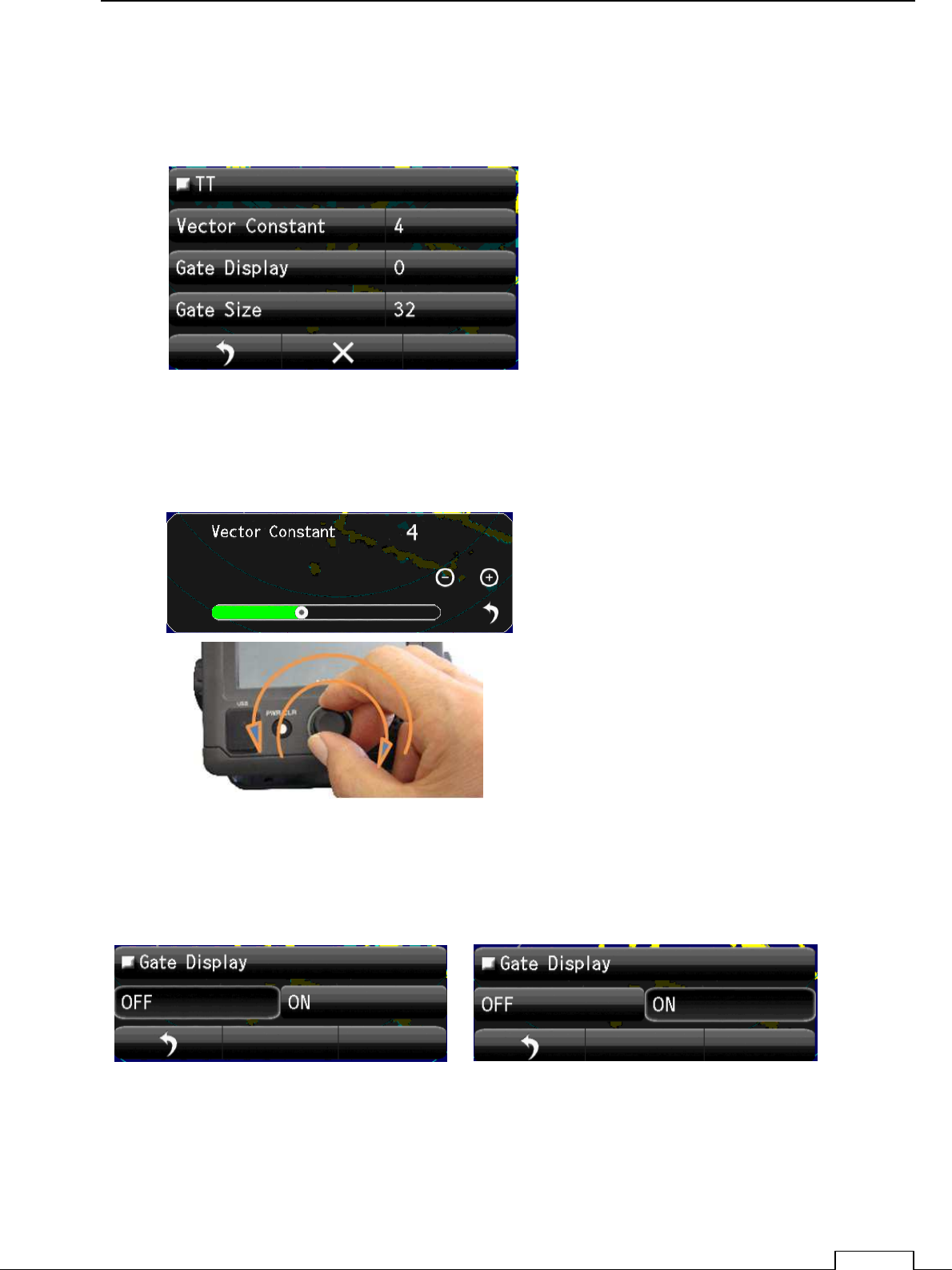
8-2 TT(TARGET TRACKING) FUNCTION
(Important adjustment. Since adjusted in factory, adjustment is not necessary in the field.)
Vector shows the movement of the target.
Vector Constant large. Vector is stable, but the response is slow.
Vector Constant small. Vector is unstable, but the response is quick..
Tap Vector Constant, setting Bar appears lower part of screen.
Set up by flick or tap + -.
Rotary knob adjusting is possible. Click and set.
Gate Display: The region automatically search target moving area.
ON: Confirmation is possible under green searching area.
OFF: Doesn’t display automatically searching area.
Chapter
8
DETAIL PERFORMANCE SE
TTING
106
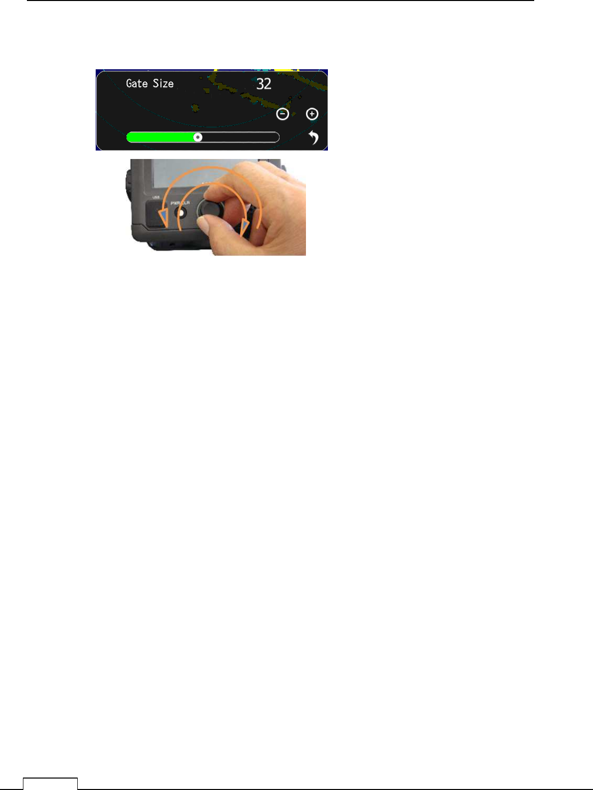
Gate Size: Set up the region size which can search the moving target automatically.
Wide region: Possible to track fast moving target, but many clutters are include.
Sometime do miss tracking because of much noise.
Narrow region Possible to track stable, but fast moving target are tend to lost.
Because of first target soon goes outside of the region.
Chapter 8 DETAIL RFORMANCE SETTING
107
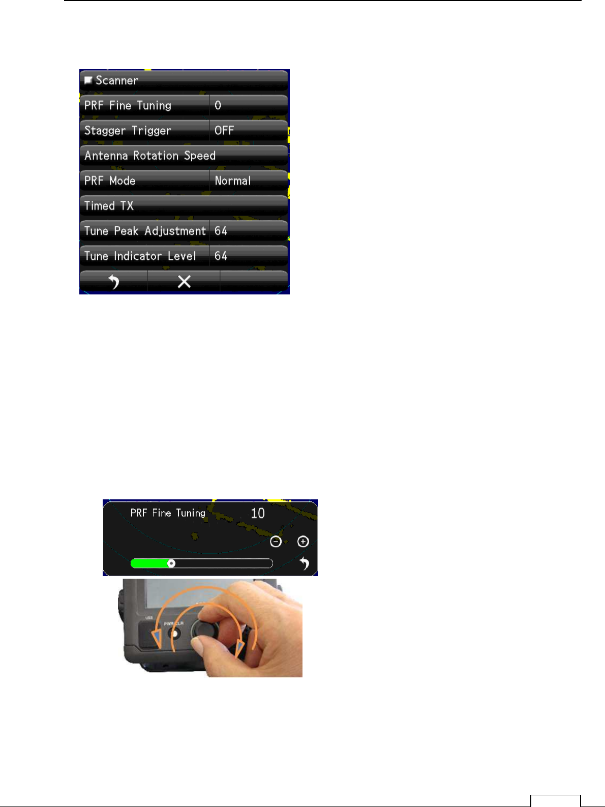
8-3 SCANNER FUNCTION
8-3-1 PULSE REPETITION FREQUENCY FINE TUNING (PRF ADJUST)
When existing the same frequency radar, in the same area, they interfere each other.
If p.r.f.(pulse reputation frequency)is the same, Interference can’t reject on the screen.
In that case shift the p.r.f. a little may decrease the radar interference.
PRF Fine Tuning:
If radar interference cannot reject completely, it is effective way to shift the PRF.
Watching the screen echo, rotate the
Rotary knob and stop when radar
interference are fade out from screen.
Chapter
8
DETAIL PERFORMANCE SE
TTING
108
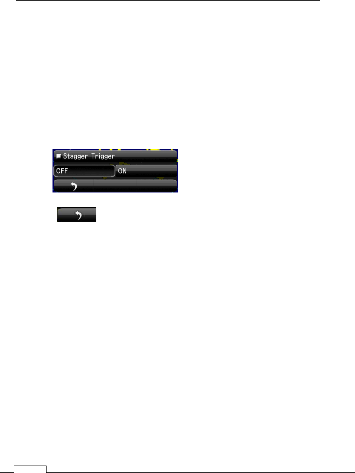
8-3-2 STAGGER TRIGGER
When existing the same frequency radar, in the same area, they interfere each other.
If p.r.f.(pulse reputation frequency)is the same, Interference can’t reject on the screen.
Another way to decease interference is shift the transmitting time randomly.
Not synchronize signal which transmit randomly is eliminate.
So decrease the other radar interference echo on screen.
ON Stagger: Stagger trigger is generated
OFF Stagger: Stagger trigger stop. (Normal trigger timing)
Select and Tap
.
Watching the screen echo, select off or on
when heavy radar interference on screen.
return to the menu
Chapter 8 DETAIL RFORMANCE SETTING
109
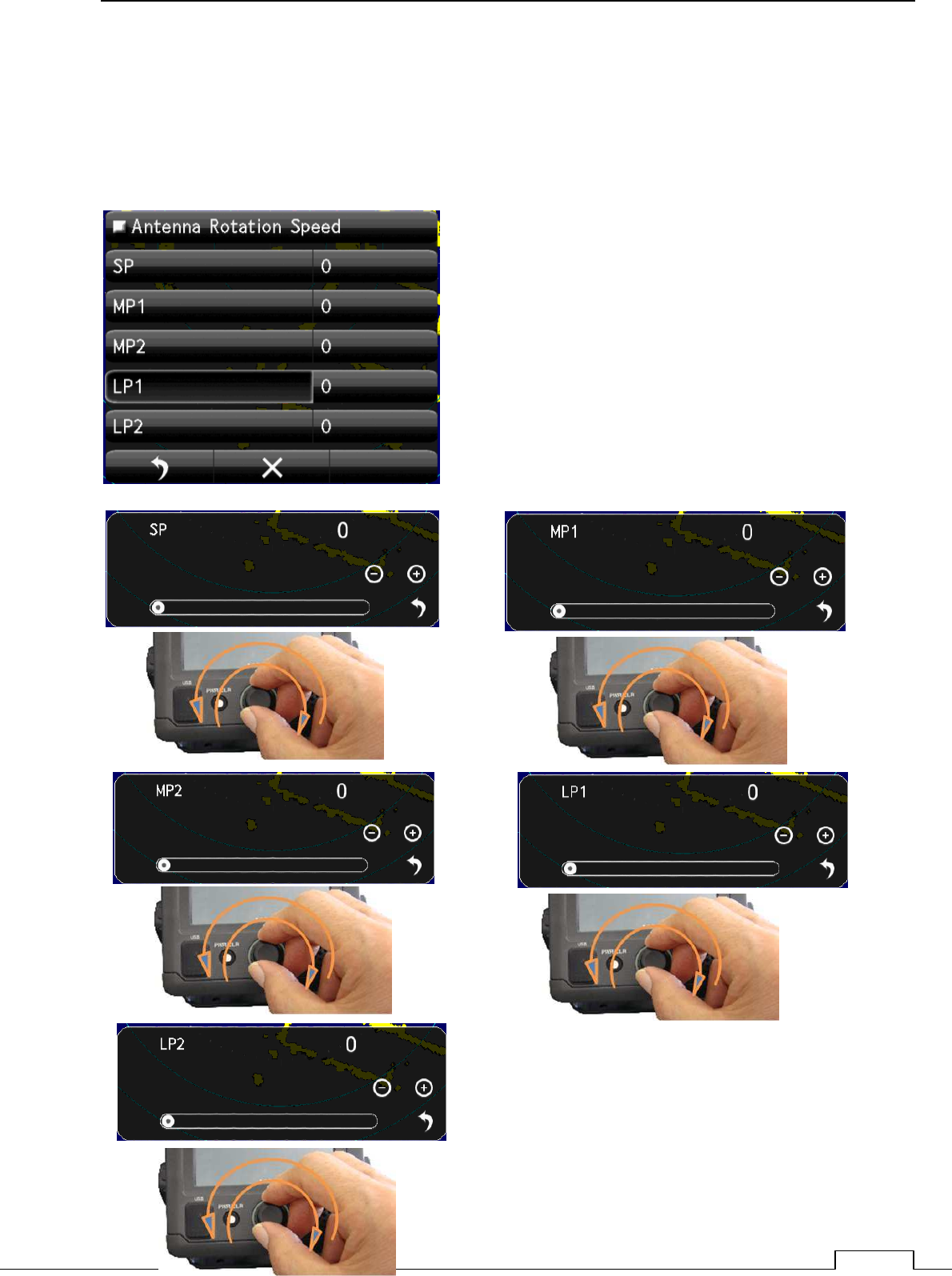
8-3-3 SCANNER ROTATIONAL SPEED
The rotational speed of inside microwave radiator is possible to change.
The sensitivity of radar are low speed is more higher.
So scanner rotation speed is possible to change according observing range.
Every pulse length can select the Antenna rotation speed.
Short range uses short pulse (SP).
Medium range uses medium pulse (MP)
Long range uses Long pulse (LP)
Shorter range requires the High speed refresh screen.
Longer range requires the Low speed for High sensitivity.
User can select rotational speed according to his request.
Chapter
8
DETAIL PERFORMANCE SE
TTING
110
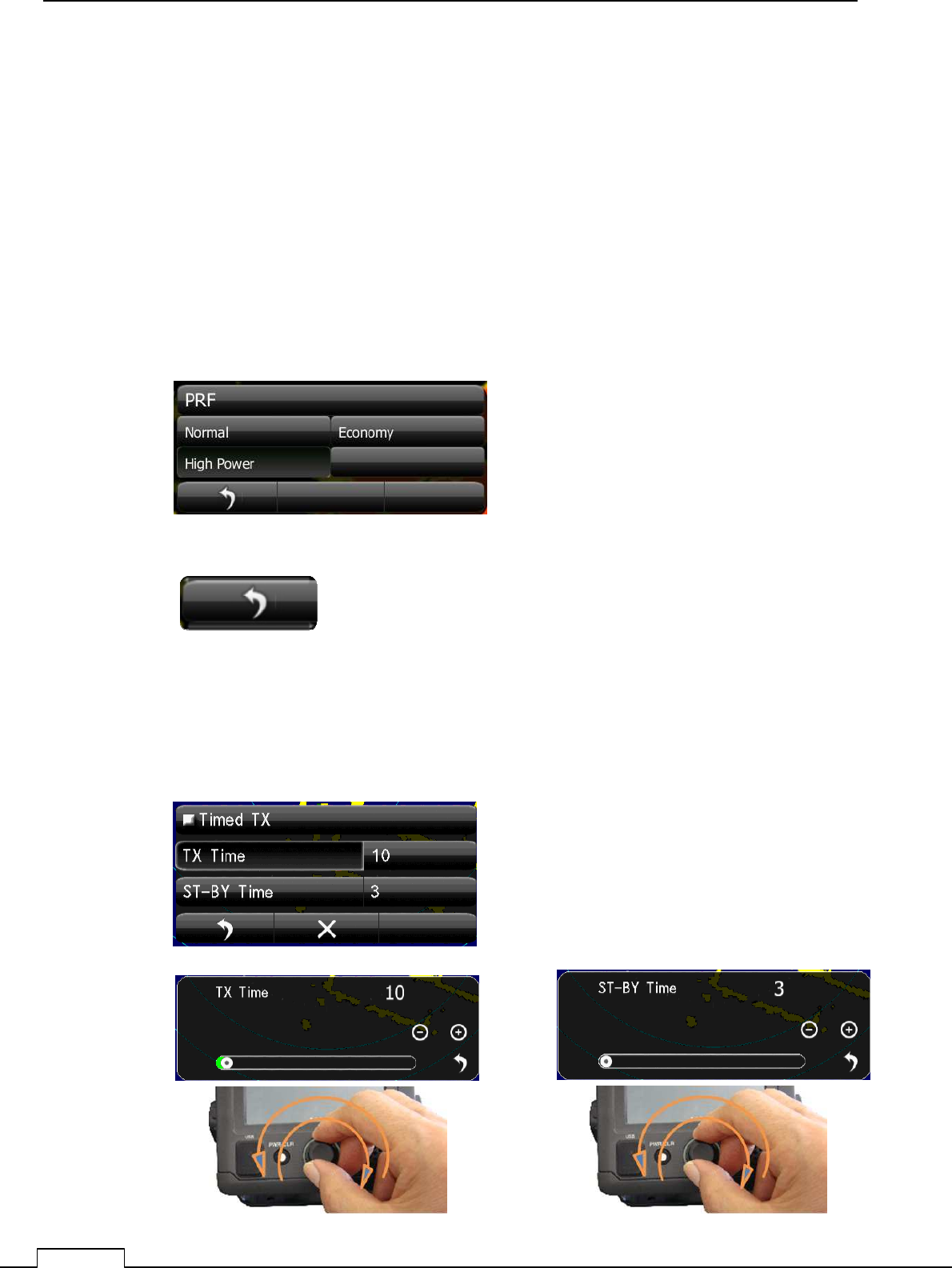
8-3-4 ECONOMY MAGNETRON SETUP (PRF , PULSE LENGTH)
The life of magnetron proportion to the total transmitting pulse power.
Low power transmission makes magnetron life more longer.
Selection
Normal: It is the usual factory setup. Usually, this is chosen.
Economy: Selected the shorter pulse, repeat frequency is also selected lowest 650 Hz.
The life of a magnetron keeps more longer time.
Sensitivity is decrease somewhat from Normal.
High Power: High sensitivity high performance.
8-3-5 TIMED TX
The life of magnetron proportion to the total transmitting pulse power.
Timed TX can save magnetron life longer.
return to the menu
Select and Tap
Chapter 8 DETAIL RFORMANCE SETTING
111
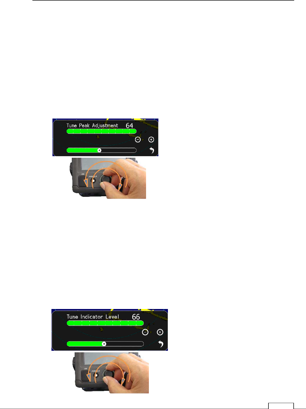
8-3-6 TUNE PEAK LEVEL
Normally, adjustment is not necessary.
(In case of adjustment the tuning peak point is shifted from maximum echo point.)
This adjustment must be done with (8-3-7 Tuning indicator) alternately.
Set RANGE at 24NM
Display tuning level indicator menu.
Tune maximum echo point.
At this point adjust tuning level, so as to seen within the green bar.
Adjusting data is 0 to 127
.
8-3-7 TUNE INDICATOR LEVEL
Normally, adjustment is not necessary.
(Adjust ,in case of tuning level is too low.)
Set RANGE at 24NM
Display the Tune Indicator menu.
Tuning region is 0 to 127
NOTE! If tuning level is too excess setting, can’t work automatic tuning function.
Adjust the tuning level bar moves within 80 to 90%.
Chapter
8
DETAIL PERFORMANCE SE
TTING
112
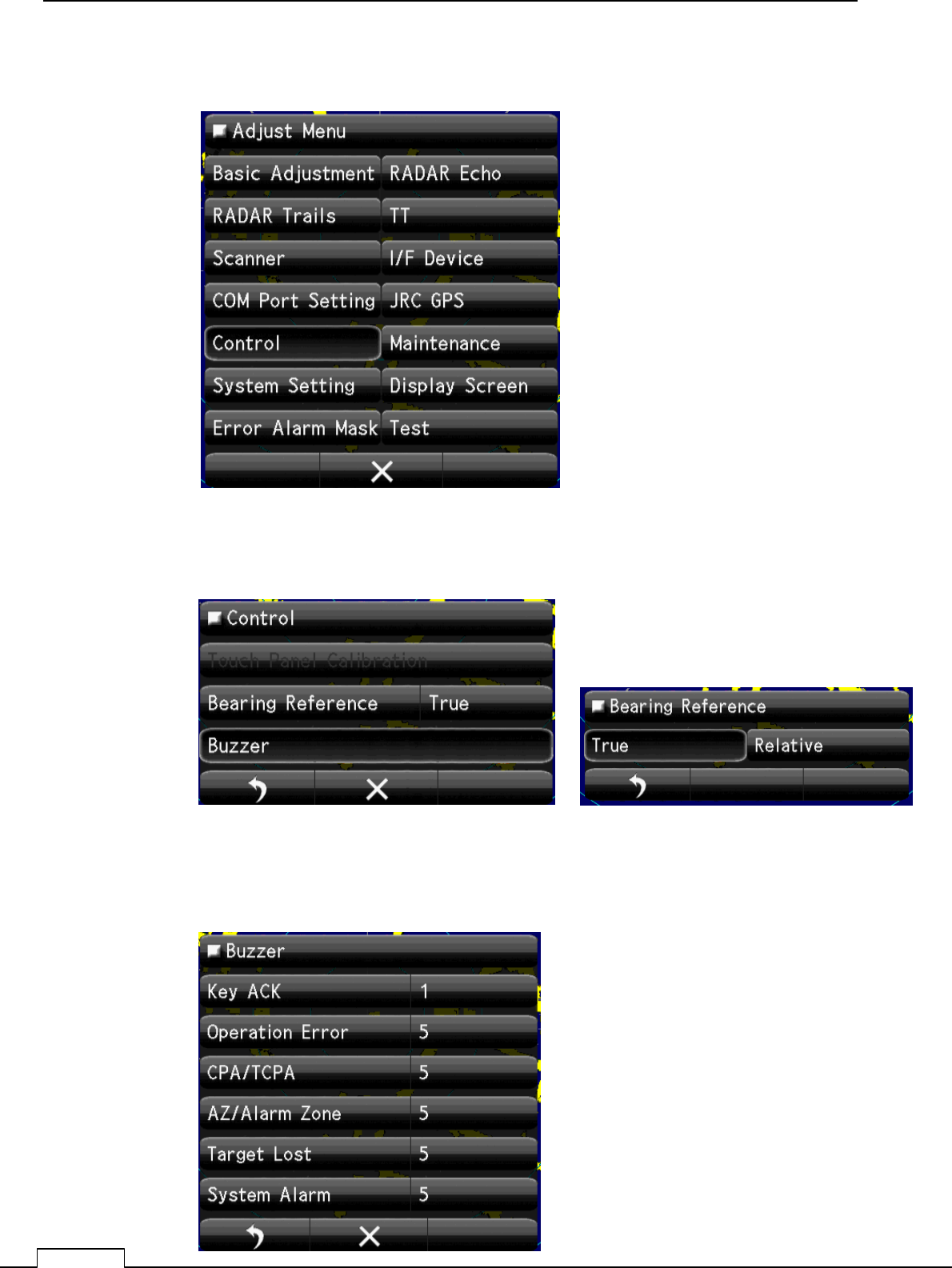
8-4 CONTROL
8-4-1 BEARING REFERENCE
8-4-2 BUZZER
Select Bearing Mode
True or Relative
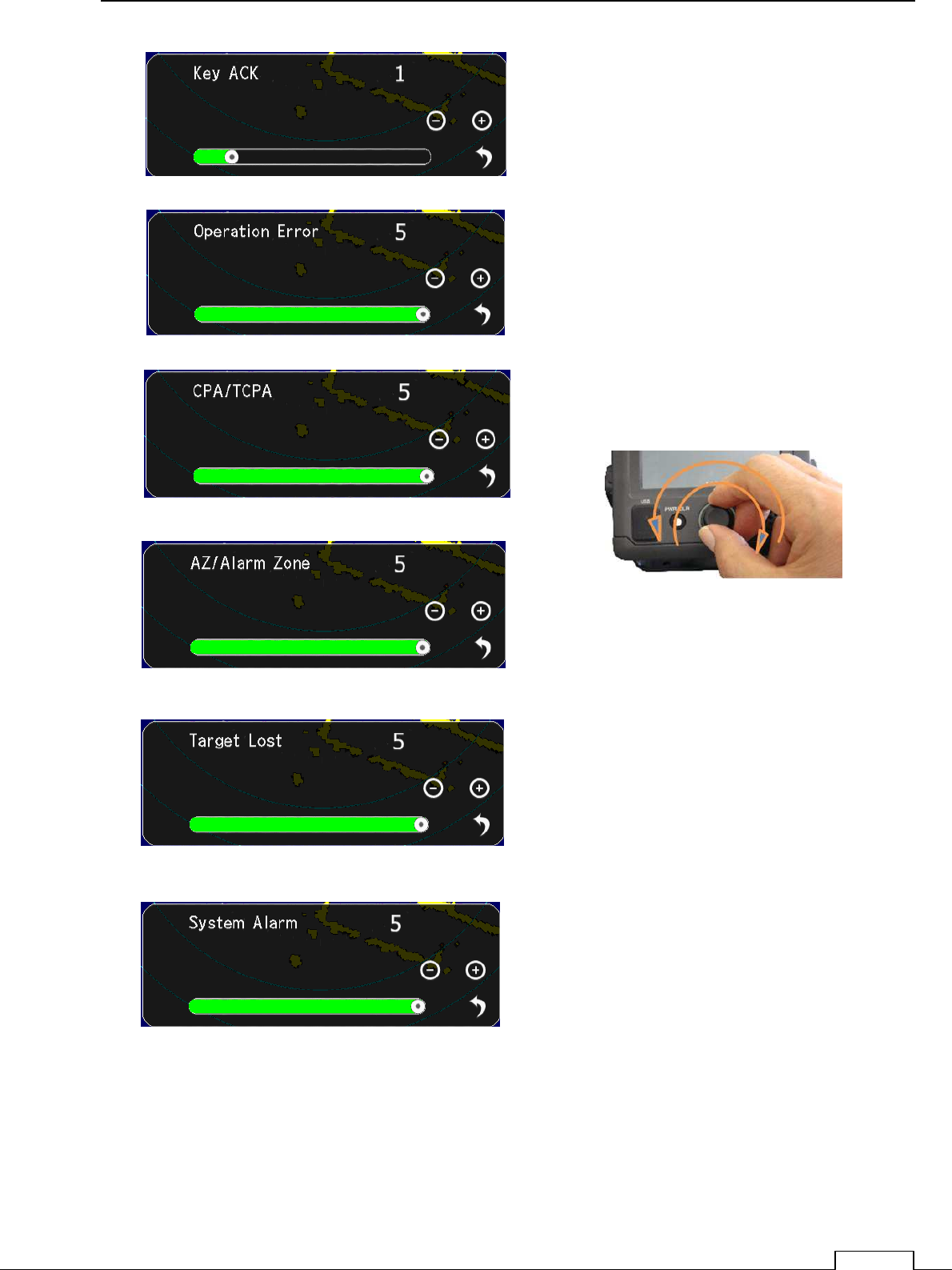
Set up the Buzzer sound Level.
Chapter 8 DETAIL RFORMANCE SETTING
113
Set up the Every sound Level.
Chapter
8
DETAIL PERFORMANCE SE
TTING
114
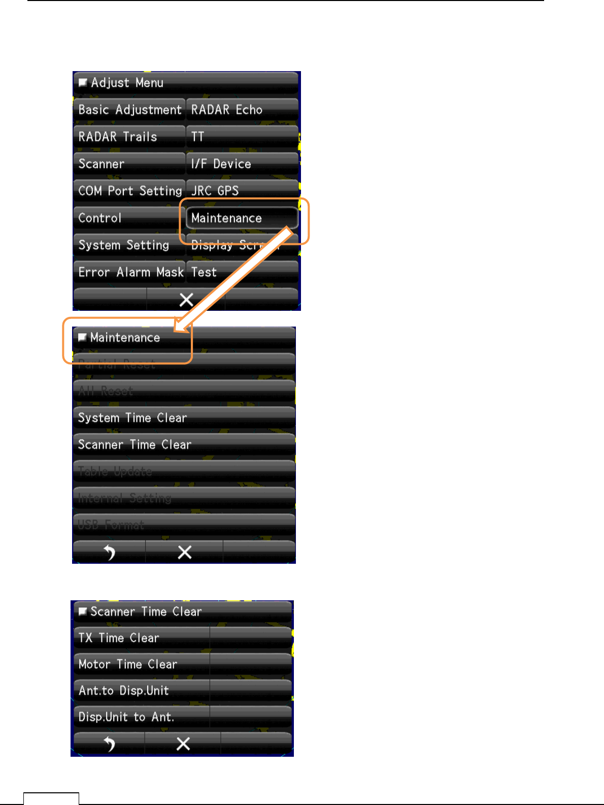
8-5 MAINTENANCE SETTING
8-5-1 SYSTEM TIME CLEAR
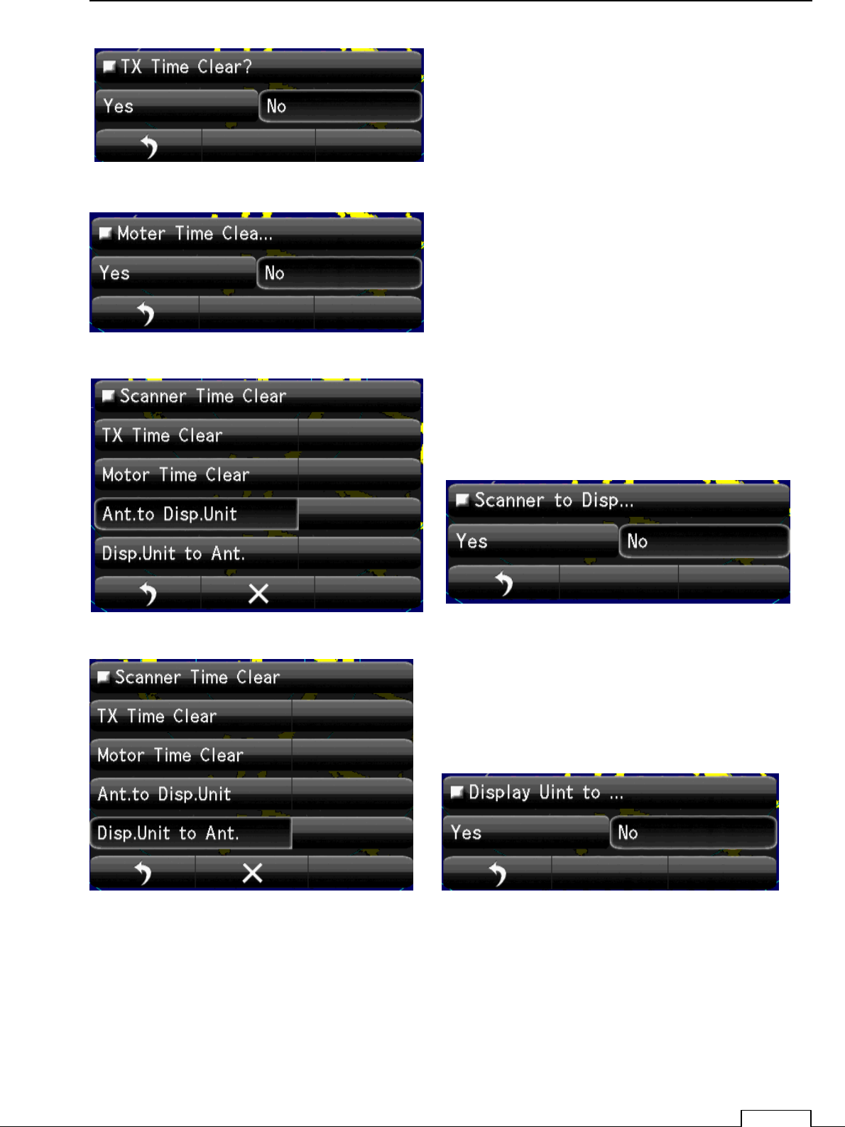
8-5-2 SCANNER TIME CLEAR
Clear System time
Clear Scanner time.
Chapter 8 DETAIL RFORMANCE SETTING
115
Chapter
8
DETAIL PERFORMANCE SE
TTING
116
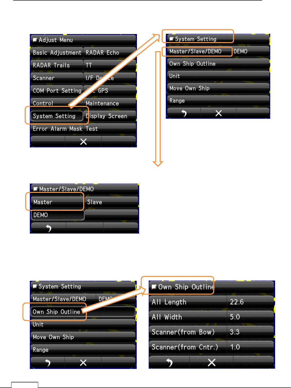
8-6 SYSTEM SETTING
8-6-1 MASTER/SLAVE/DEMO
8-6-2 Own Ship Outline
Set up the operating mode.
Mode selection of display.
Master: control scanner.(Stand alone.).
Slave: Receive another radar signal and display. can’t
control scanner.
Demo: When use as carrying out the demonstration
Select Master
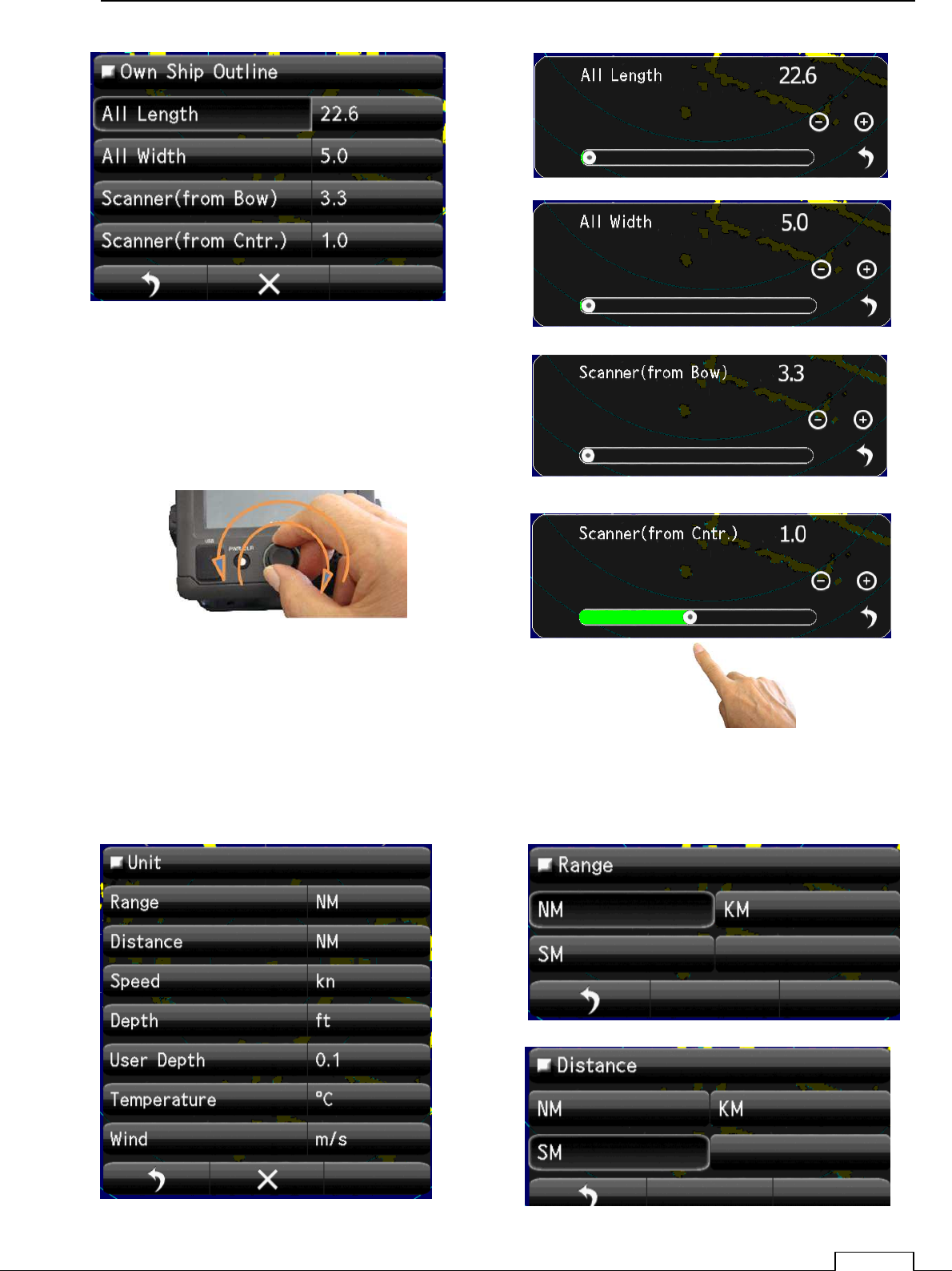
Set up the Own ship’s Outline, length and scanner position.
Chapter 8 DETAIL RFORMANCE SETTING
117
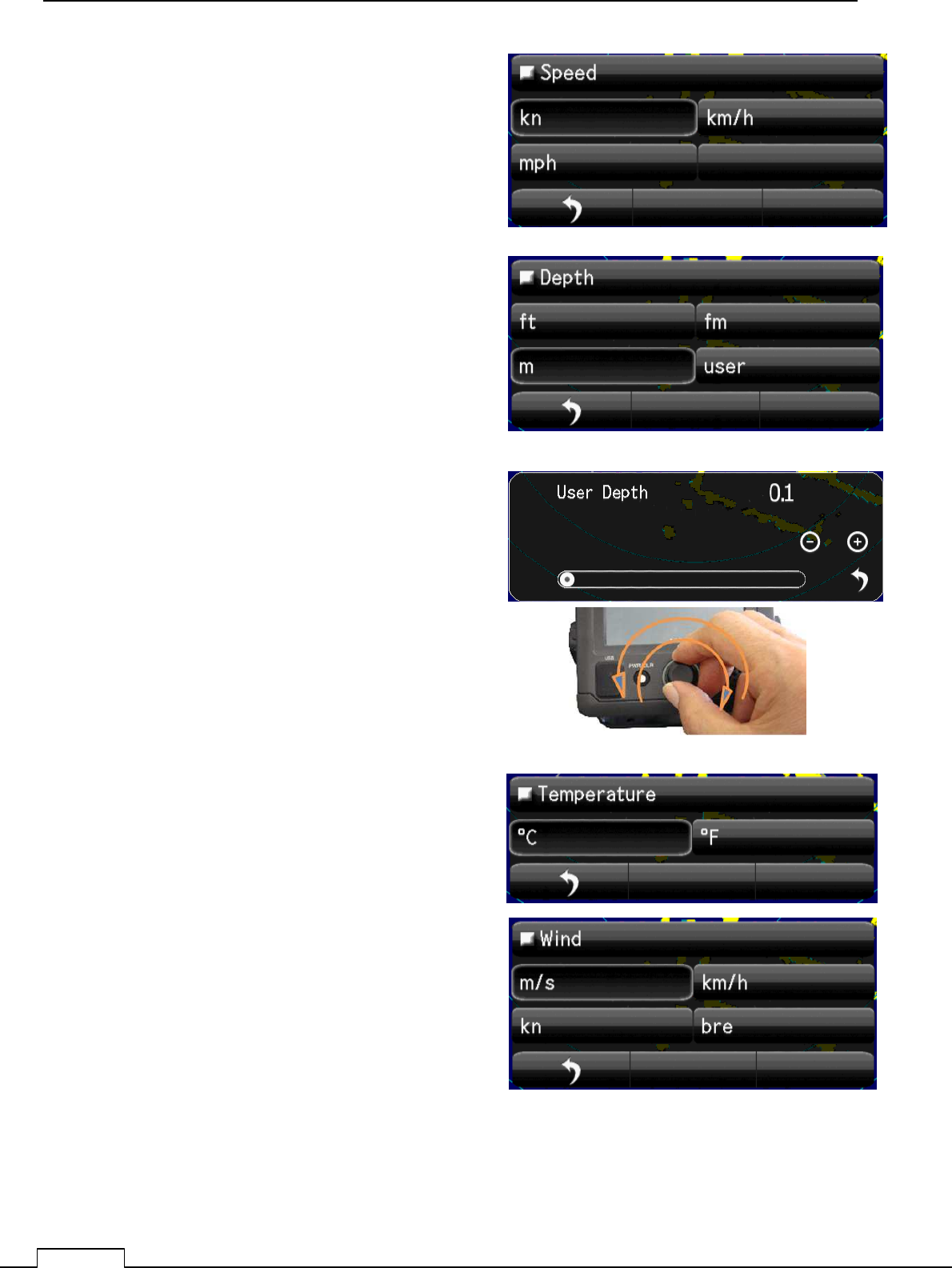
8-6-3 UNIT
Display units, such as distance, speed, depth of water, water temperature, and wind velocity.
“NM”,” km”,” ktn”, etc. are possible to set up.
Chapter
8
DETAIL PERFORMANCE SE
TTING
118
Chapter 8 DETAIL RFORMANCE SETTING
119
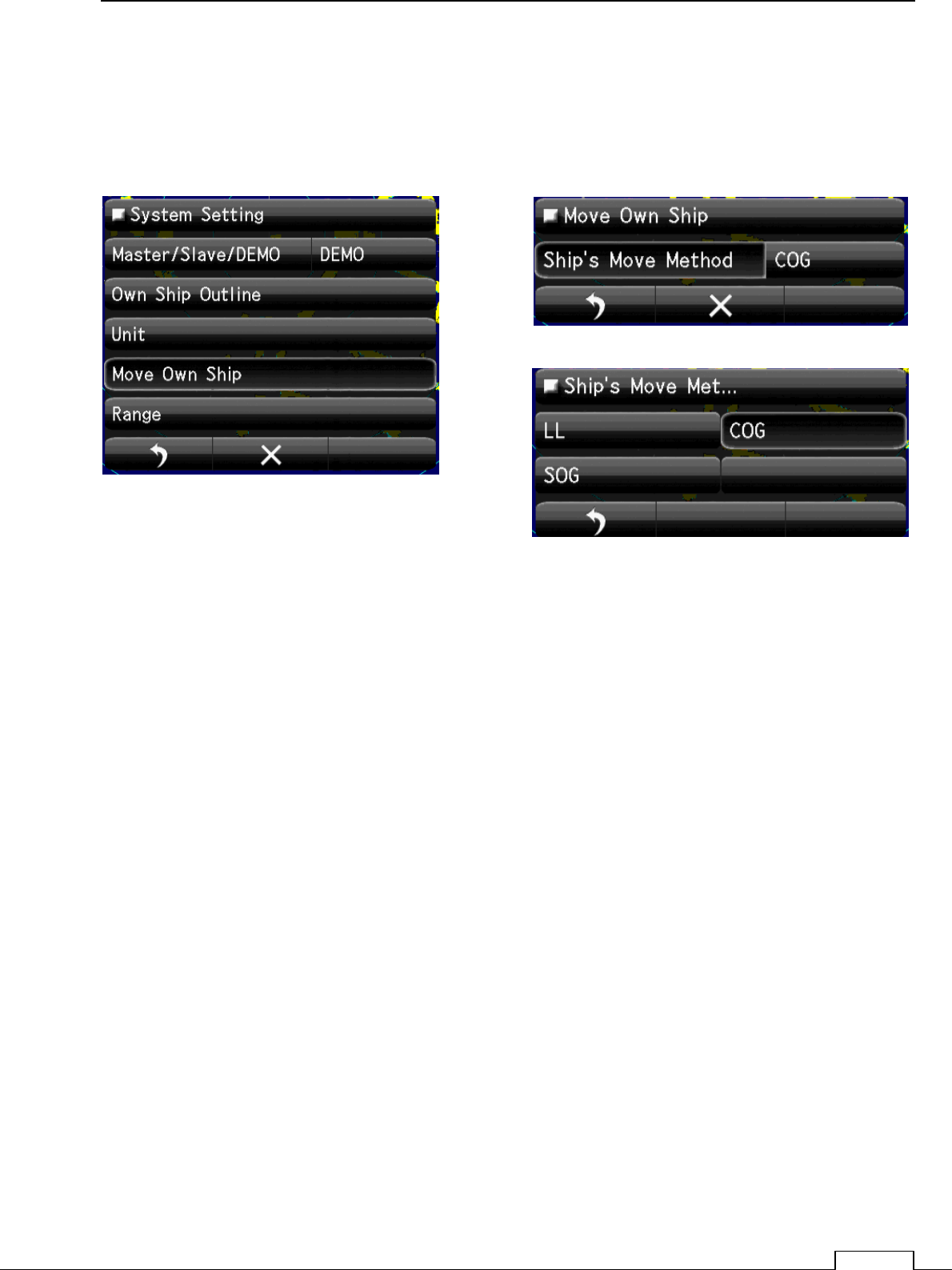
8-6-4 MOVE OWN SHIP
Means of Moving own ship.
Select
GPS, LOG, Dead Reckoning (dead-reckoning navigation), etc.
Chapter
8
DETAIL PERFORMANCE SE
TTING
120
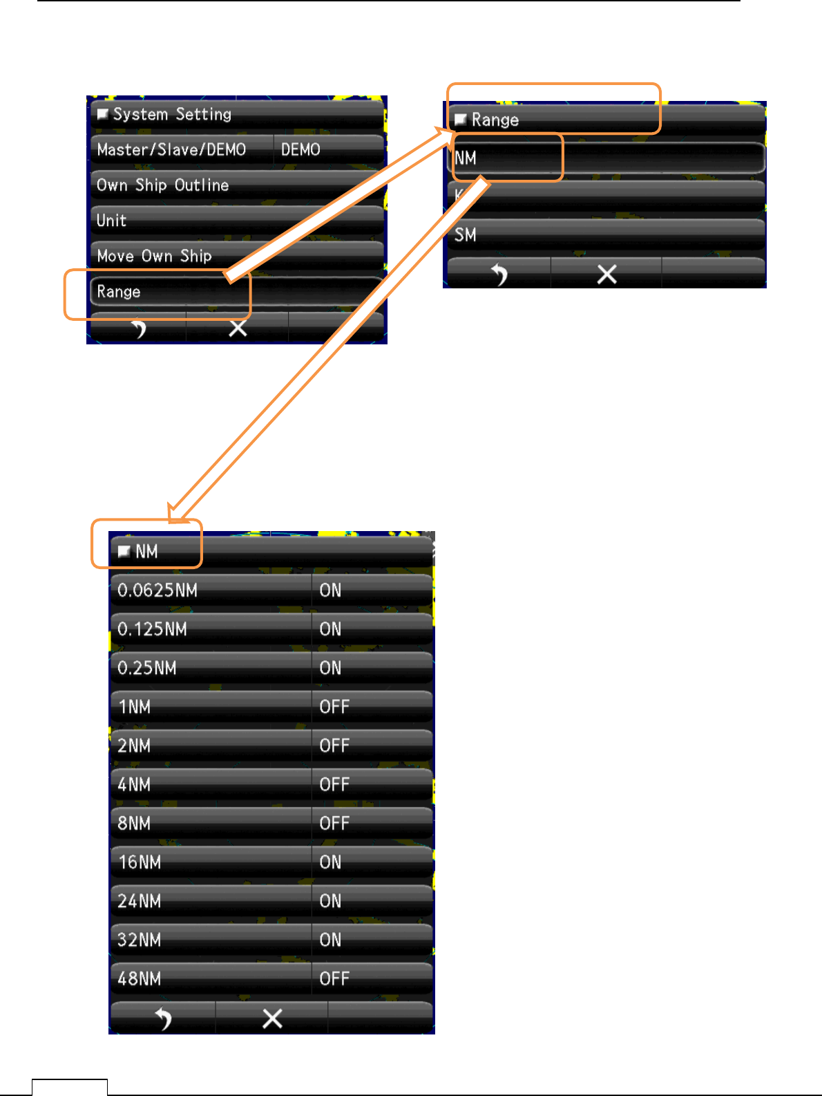
8-6-5 USE RANGE SELECT
Select the using unit. “NM”,”KM”,”SM”.
Select the using NM range “ON”.
Not using range, set up “OFF”.
Chapter 8 DETAIL RFORMANCE SETTING
121
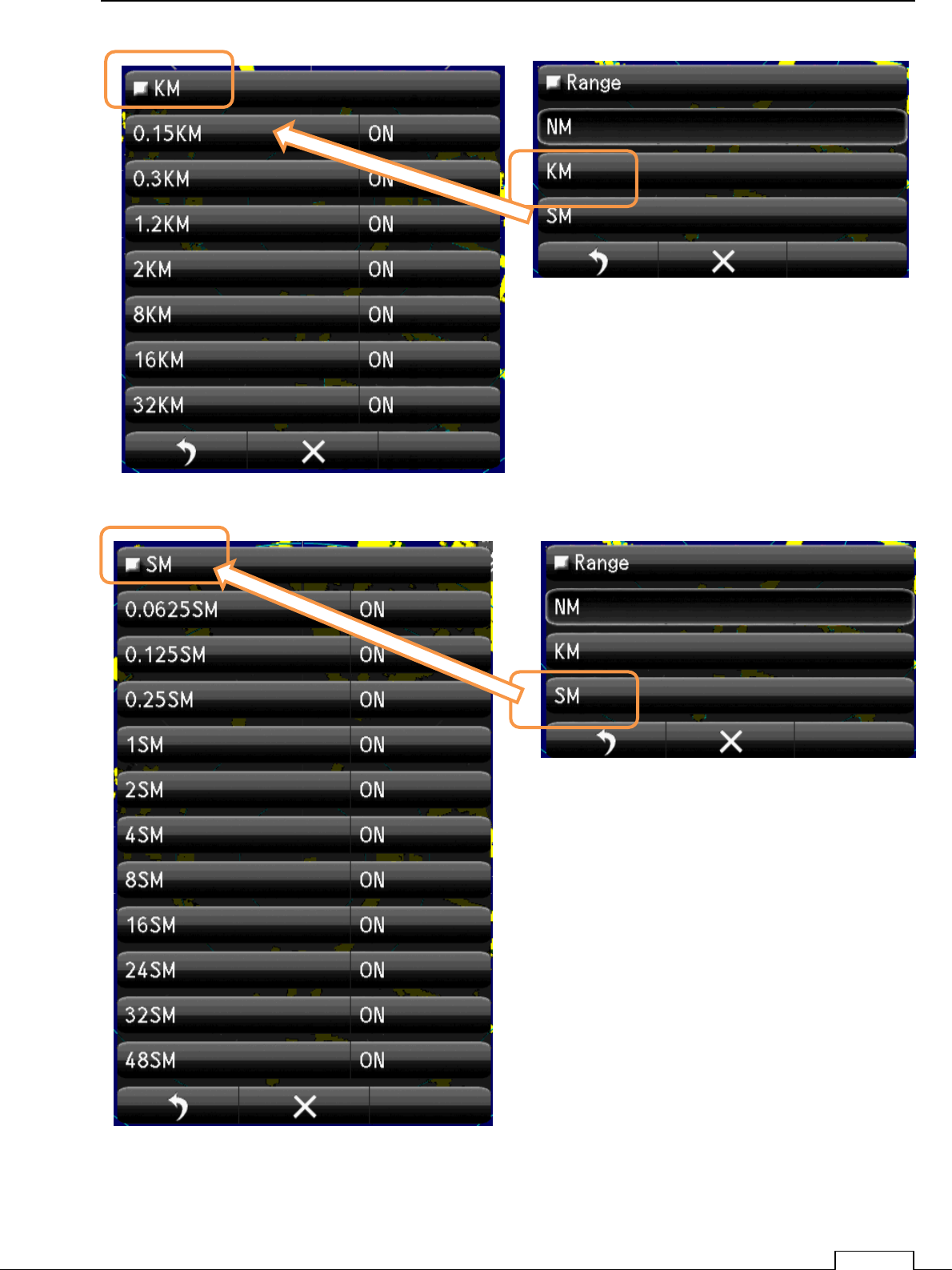
Select the using KM range “ON”.
Not using range, set up “OFF”.
Select the using SM range “ON”.
Not using range, set up “OFF”.
Chapter
8
DETAIL PERFORMANCE SE
TTING
122
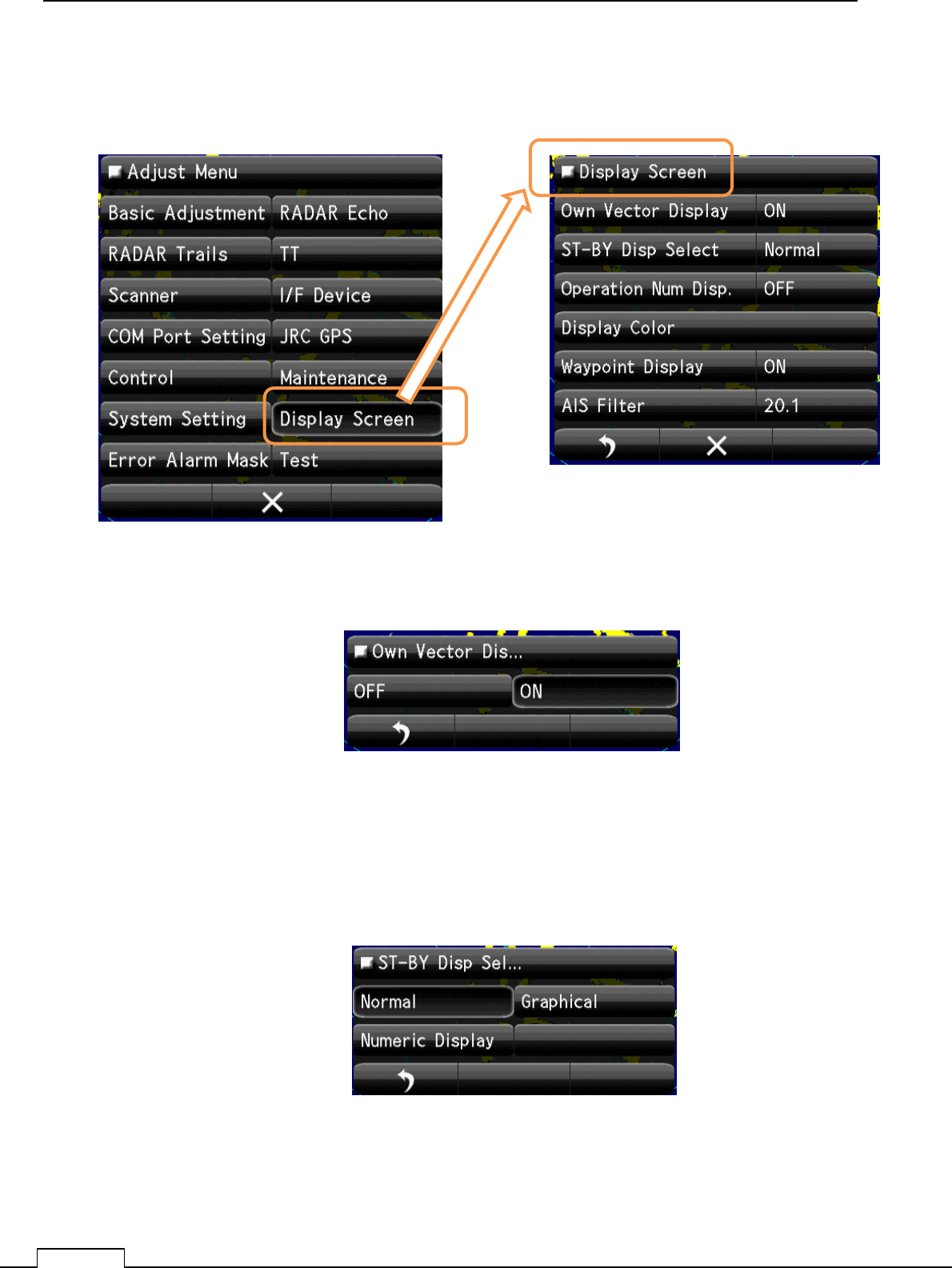
8-7 DISPLAY SCREEN
Various display setting..
8-7-1 OWN VECTOR DISPLAY
8-7-2 ST-BY DISP SELECT
Selections whether at stand by state, display the numeric data on screen or not.
Select the using SM range “ON”.
Not using range, set up “OFF#.
Select the Own Vector display ON or OFF.
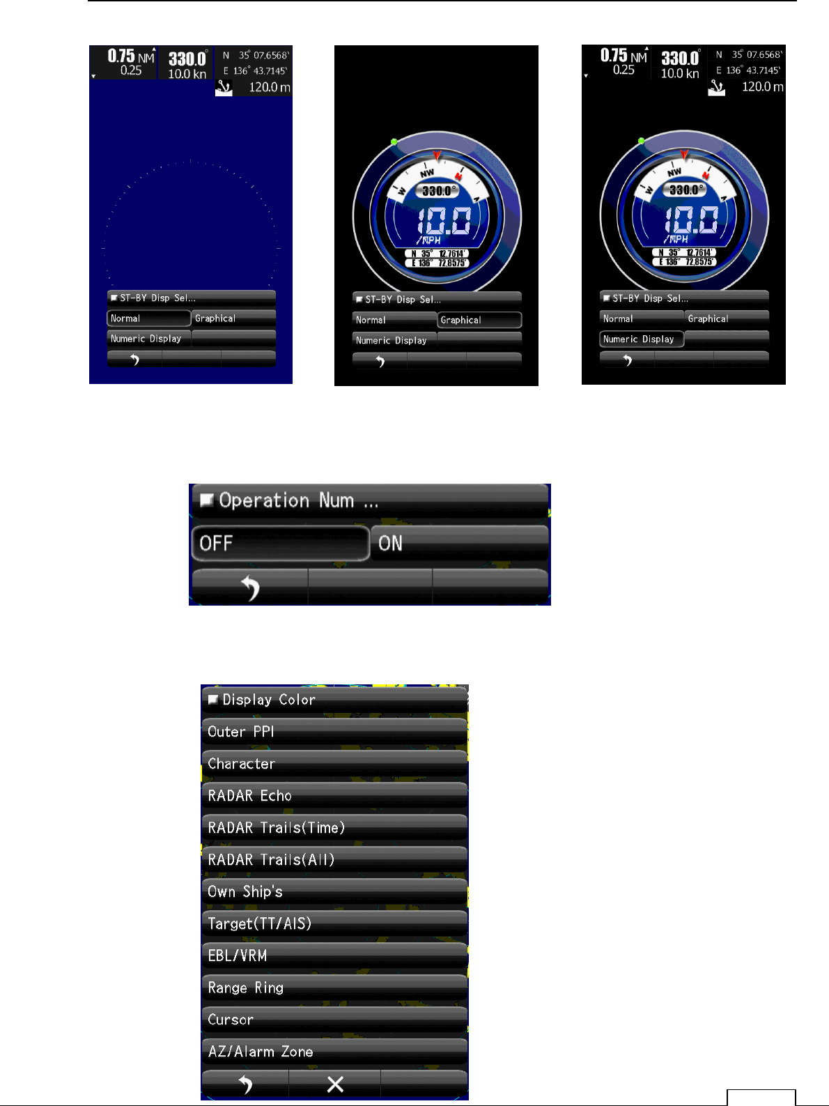
Select the ST-BY Display. “Normal” “Graphical” “Numeric”.
Chapter 8 DETAIL RFORMANCE SETTING
123
8-7-3 OPERATION NUMERICAL DISPLAY
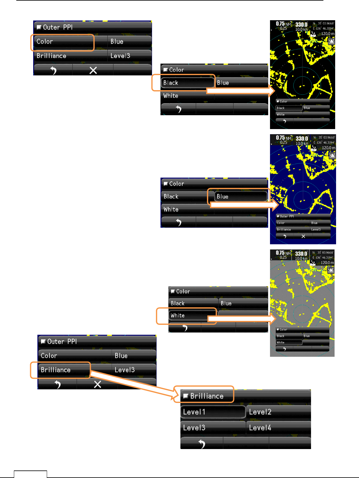
8-7-4DISPLAY COLOR
“Normal” “Graphical” “Numeric”.
Select the Display. OFF or ON
Setting of screen color.
Chapter
8
DETAIL PERFORMANCE SE
TTING
124
Black screen color.
Select Brilliance Level
Blue screen color.
White screen color.
Chapter 8 DETAIL RFORMANCE SETTING
125
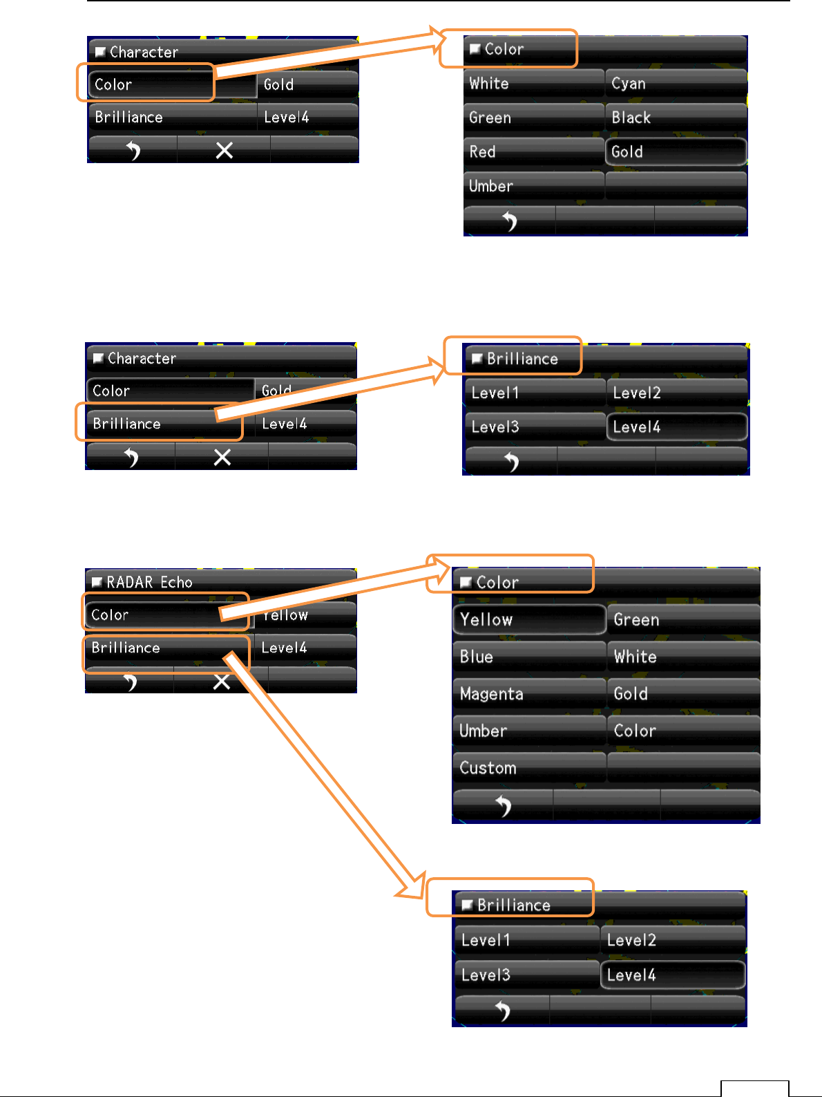
Select Color
Select Character Color
Select Brilliance. Select Brilliance. Level.
Select Brilliance. Level.
Select Echo Color
Chapter
8
DETAIL PERFORMANCE SE
TTING
126
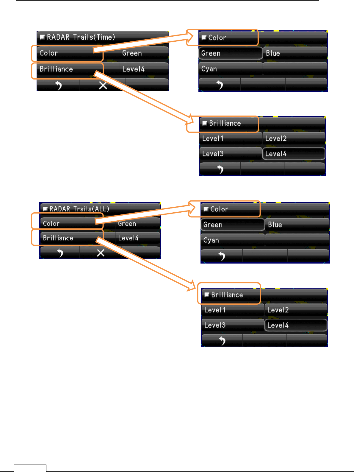
Select Brilliance. Level.
Select Trails(Time) Color
Select Brilliance. Level.
Select Trails(All) Color
Chapter 8 DETAIL RFORMANCE SETTING
127
Select Brilliance. Level.
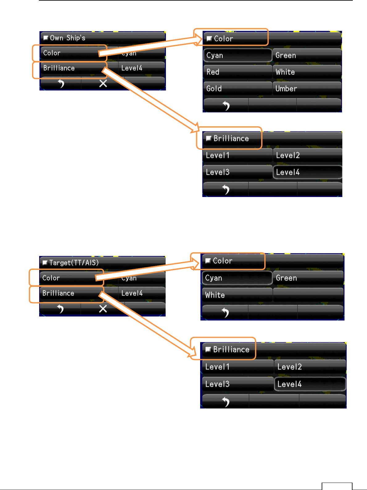
Select Own Ships Color
Select Brilliance. Level.
Select Target (TT/AIS) Color
Chapter
8
DETAIL PERFORMANCE SE
TTING
128
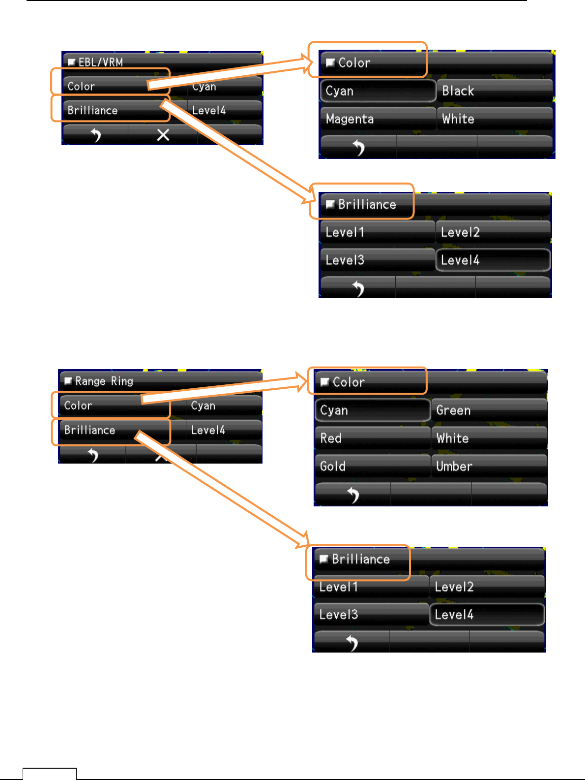
Select Brilliance. Level.
Select EBL/VRM Color
Select Brilliance. Level.
Select Range Ring Color
Chapter 8 DETAIL RFORMANCE SETTING
129
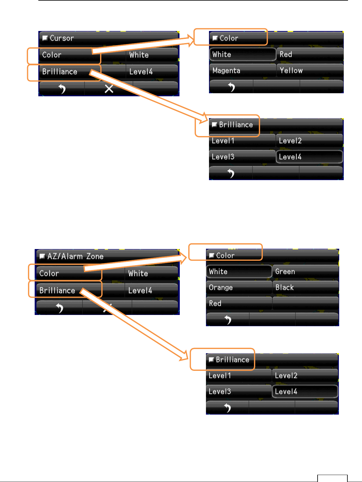
Select Brilliance. Level.
Select Cursor Color
Select Brilliance. Level.
Select AZ/Alarm Color
Chapter
8
DETAIL PERFORMANCE SE
TTING
130
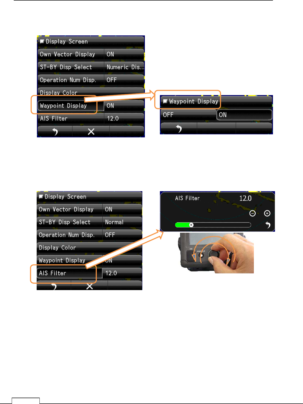
8-7-5WAYPOINT DISPLAY
8-7-6AIS FILTER
Select Waypoint Display. Select Waypoint Display “ON” or ”OFF”.
Set up AIS Filter Range.
Select AIS Filter
Chapter 8 DETAIL RFORMANCE SETTING
131
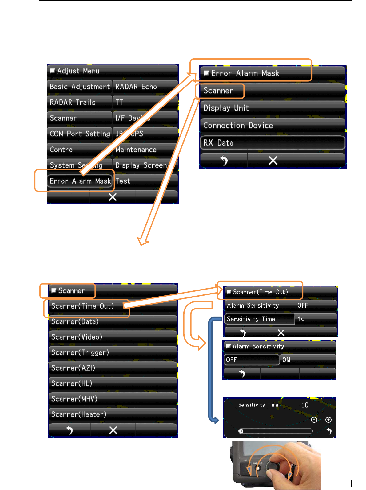
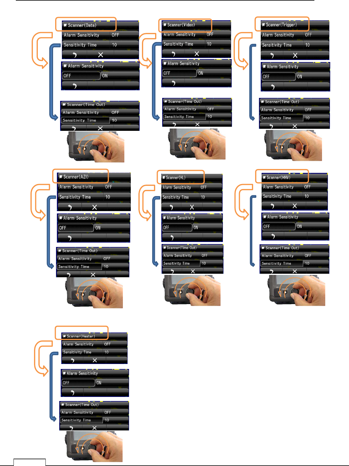
8-8 ERROR ALARM MASK
Ignore the unnecessary error signal’s alarm.
8-8-1 SCANNER
The error signal generated in the scanner.
Chapter
8
DETAIL PERFORMANCE SE
TTING
132
Scanner(Data)
Scanner(Video) Scanner(Trigger)
Scanner(Azi) Scanner(HL) Scanner(MHV)
Scanner(Heater)
Chapter 8 DETAIL RFORMANCE SETTING
133
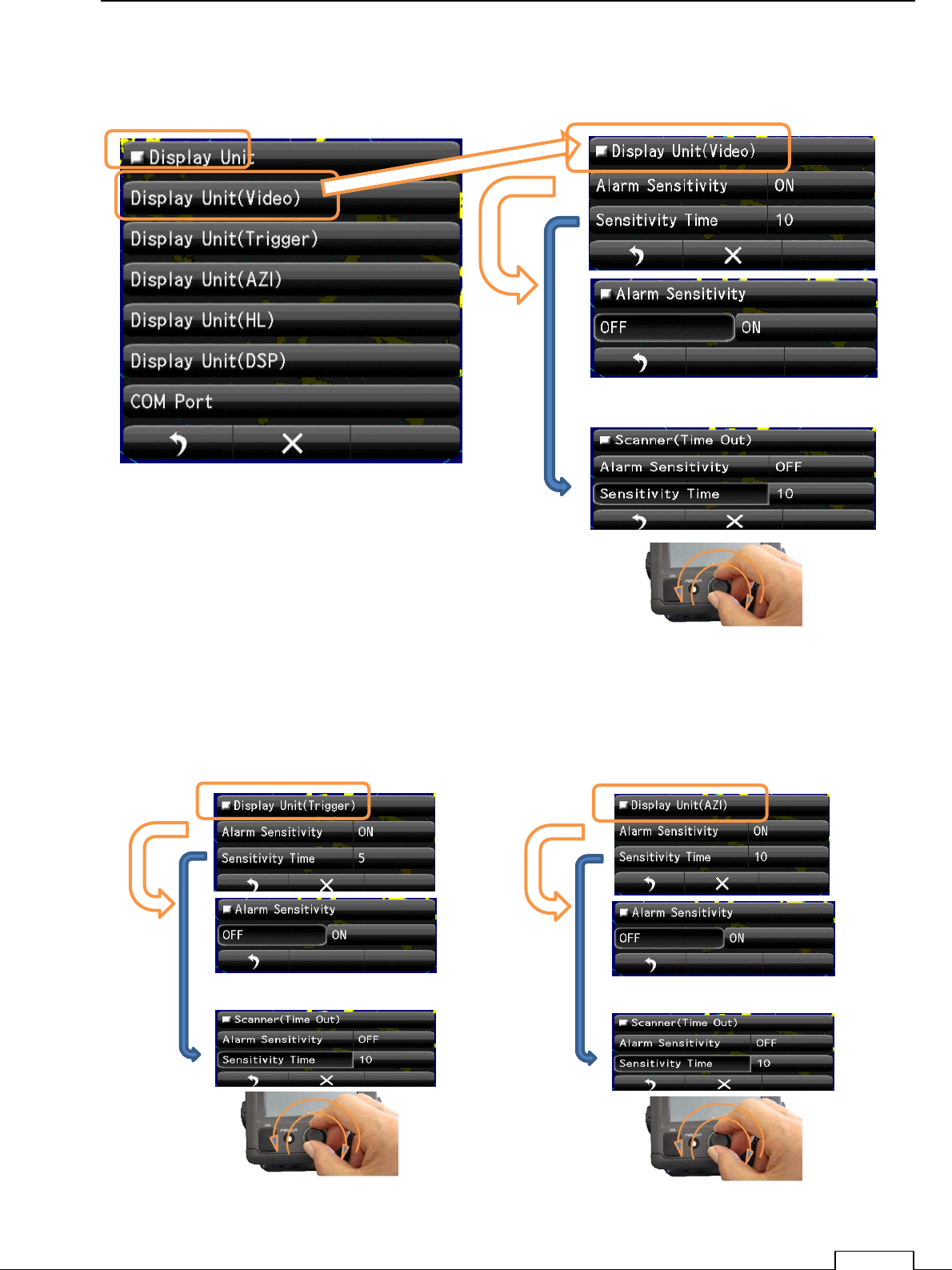
8-8-2 DISPLAY UNIT
The error signal generated in the display unit.
Display Unit(Video)
Display Unit(Trigger) Display Unit(AZI)
Chapter
8
DETAIL PERFORMANCE SE
TTING
134
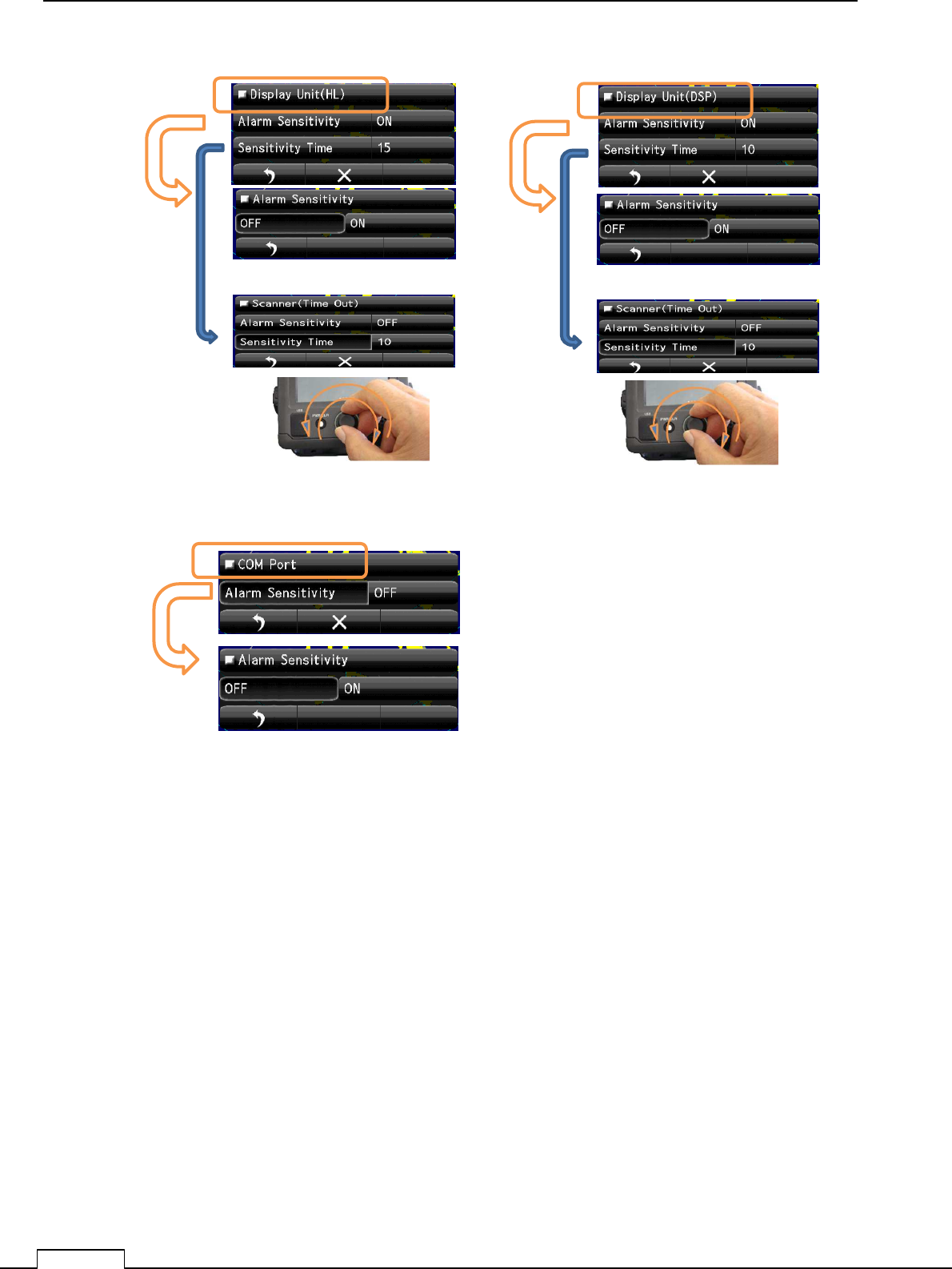
]
Display Unit(HL) Display Unit(DSP)
COM Port
Chapter 8 DETAIL RFORMANCE SETTING
135
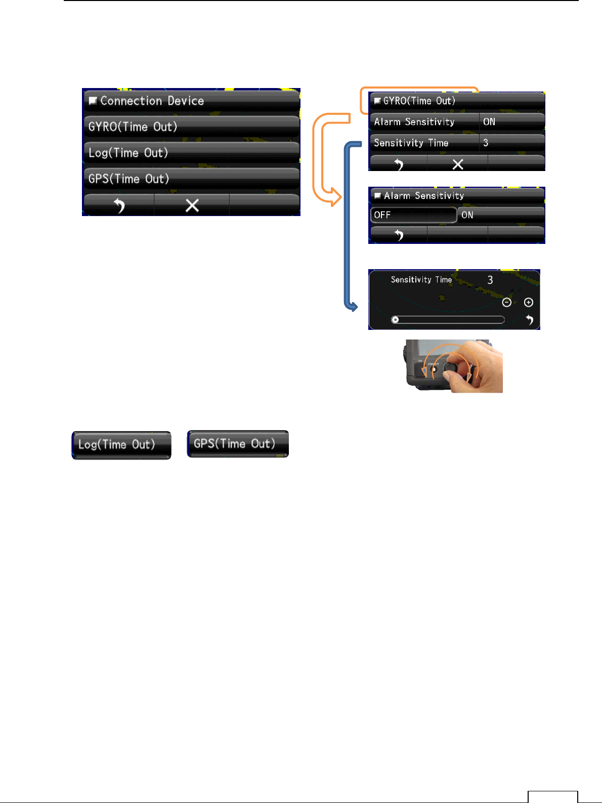
8-8-3 CONNECTION DEVICE
The error signal generated about the connected device.
Gyro(Time Out)
Log (Time Out) GPS (Time Out) are the same method.
Chapter
8
DETAIL PERFORMANCE SE
TTING
136
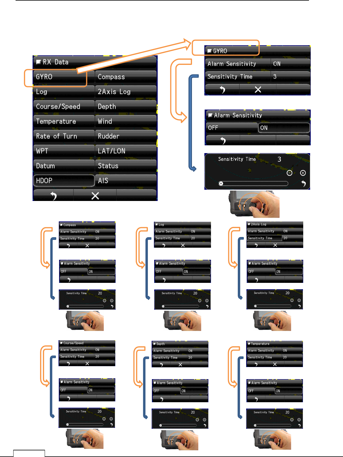
8-8-4 RX DATA
The error signal about receiving data from another equipment.
Compass data Alarm Log data Alarm 2Axis Log data Alarm
Chapter 8 DETAIL RFORMANCE SETTING
137
Course / Speed data Alarm Depth data Alarm Temperature data Alarm
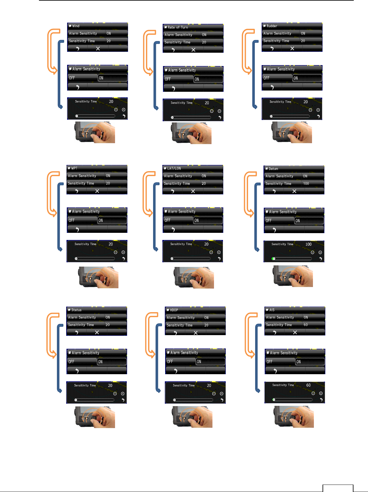
Wind data Alarm Rate of Turn data Alarm 2Rudder data Alarm
WPT data Alarm LAT/LON data Alarm Datum data Alarm
Status data Alarm HDOP data Alarm AIS data Alarm