Japan Radio 875S35J-A Mobile Radio User Manual Operator s Manual
Japan Radio Co Ltd. Mobile Radio Operator s Manual
UserManual.wiki
>
Japan Radio
>
875S35J A User Manual
Users Manual
Navigation menu
Upload a User Manual
Namespaces
Wiki Guide
HTML
PDF
Info
Views
User Manual
Discussion / Help
Navigation


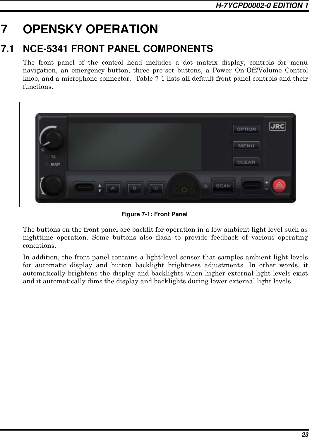
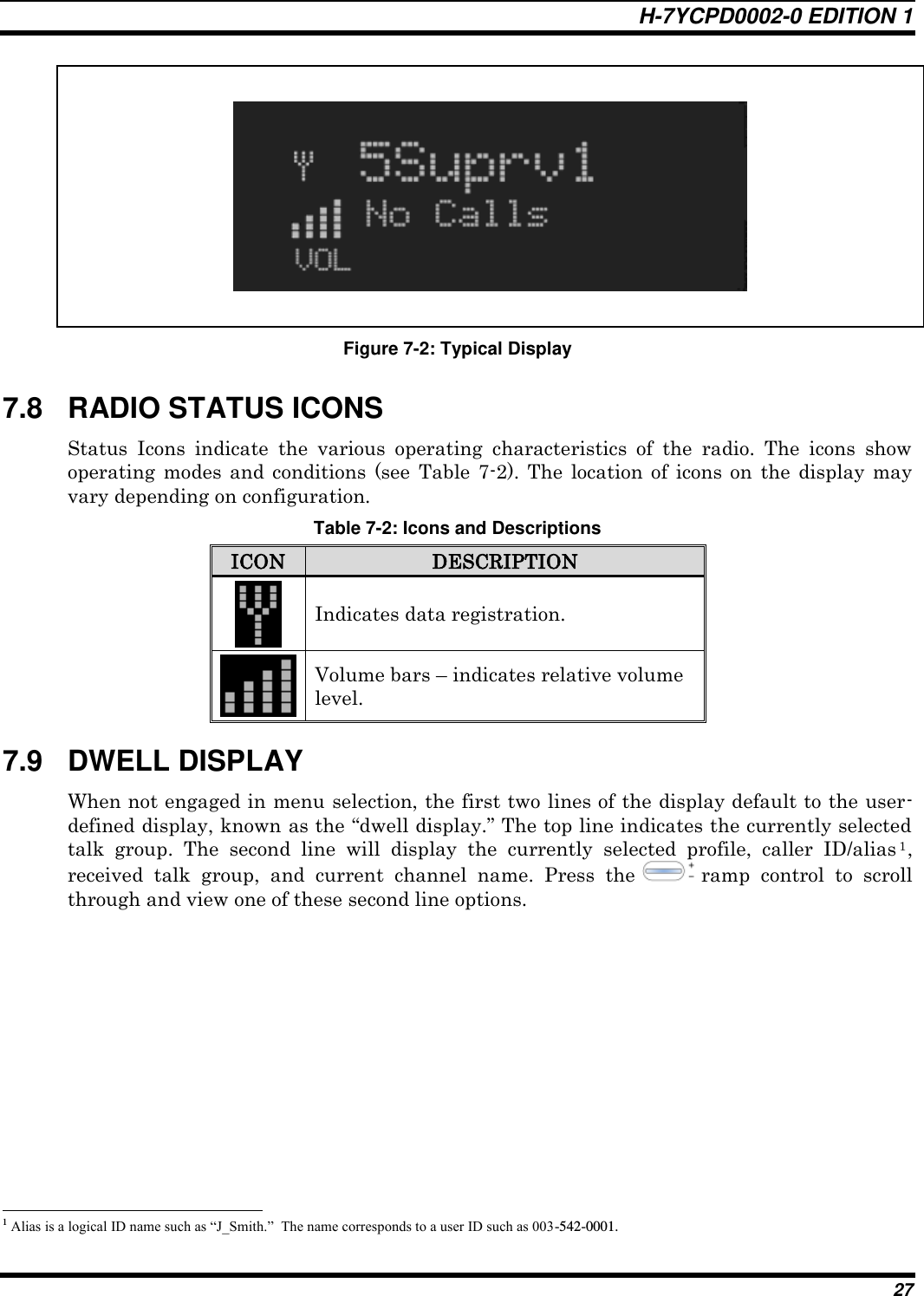
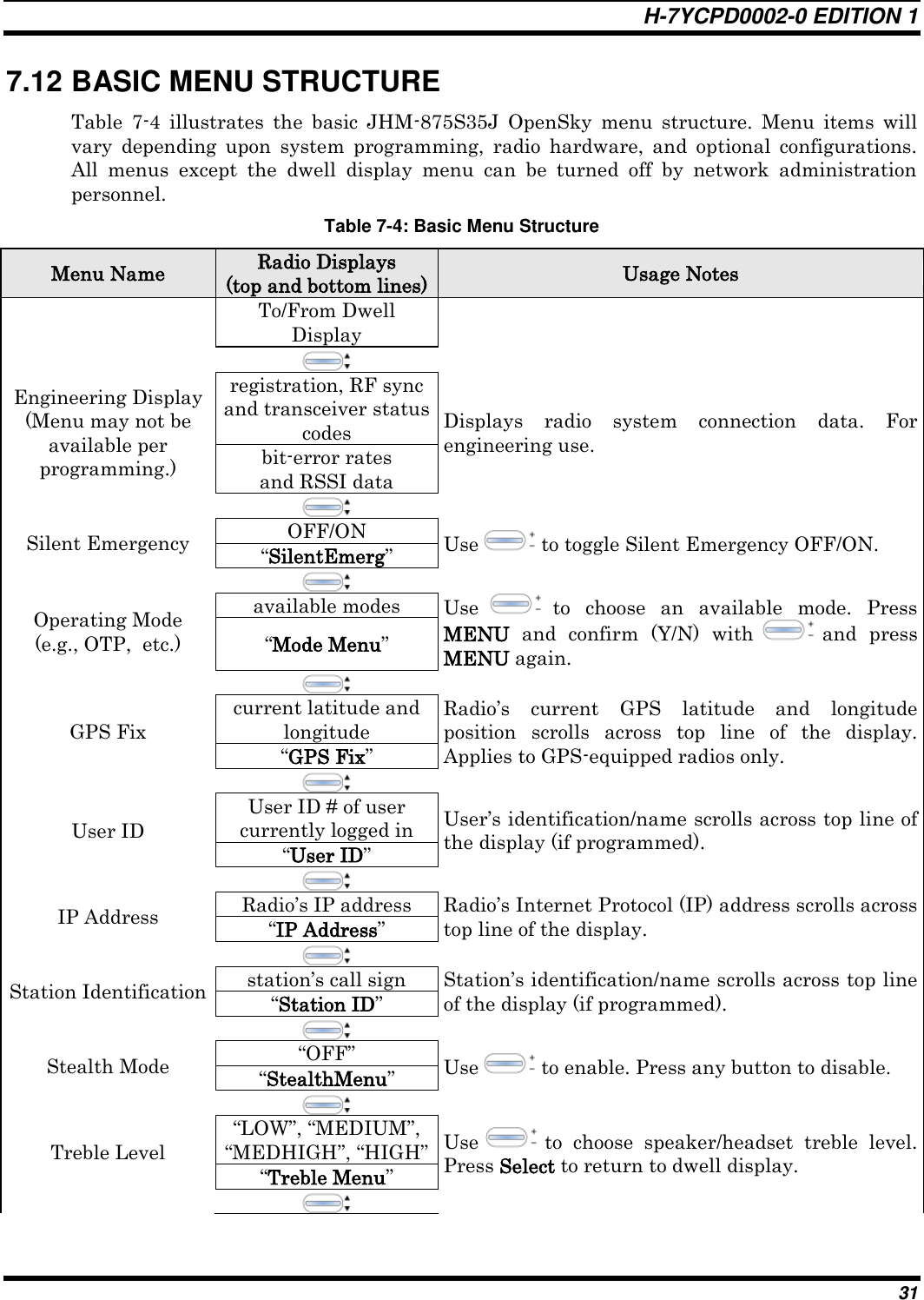
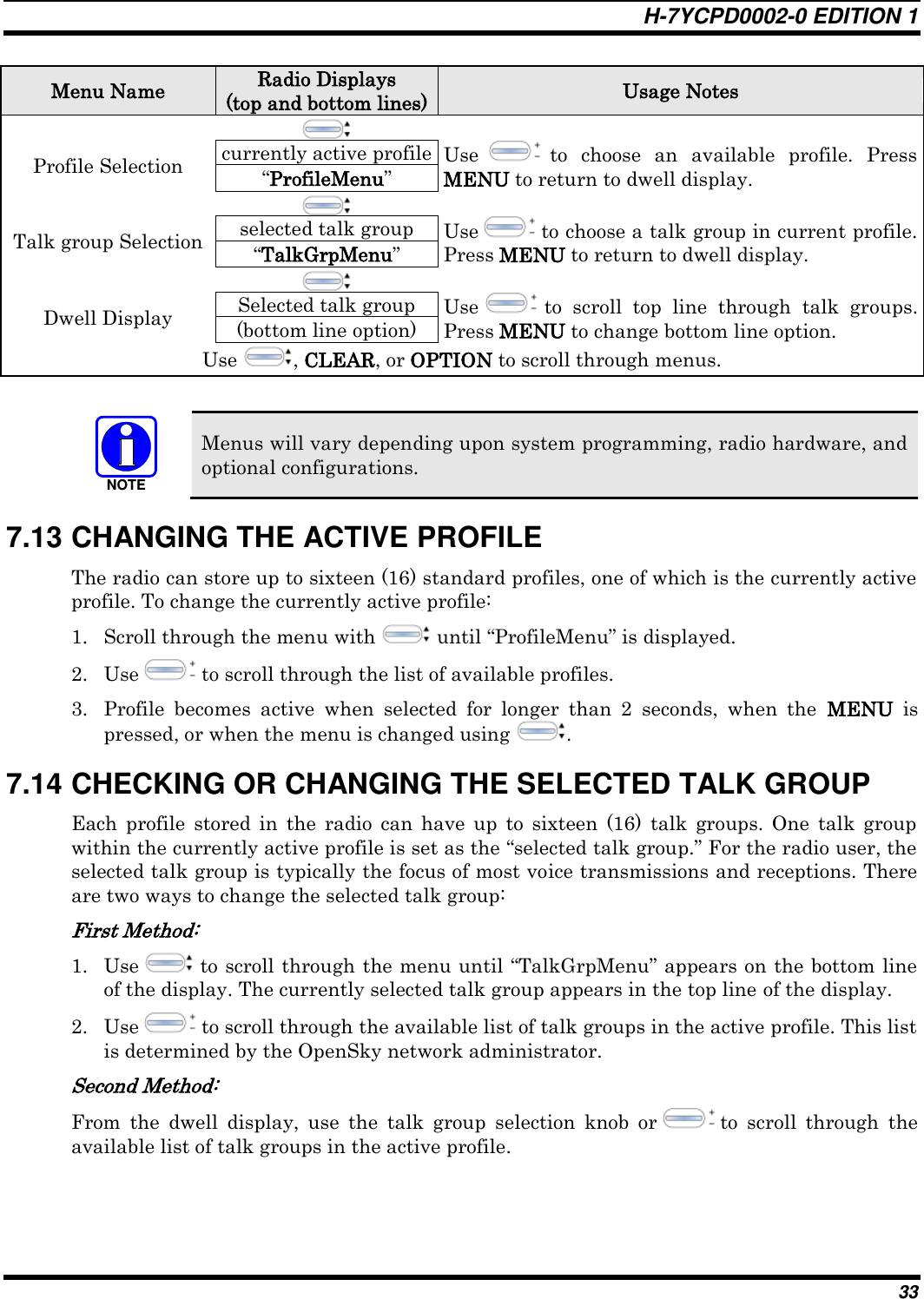
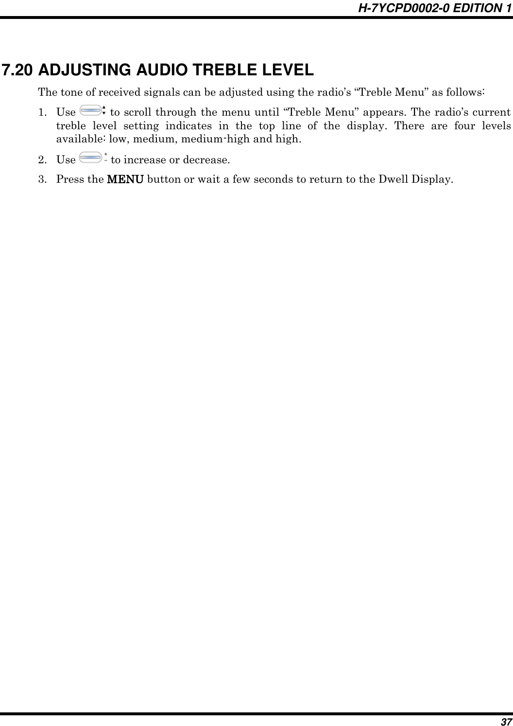
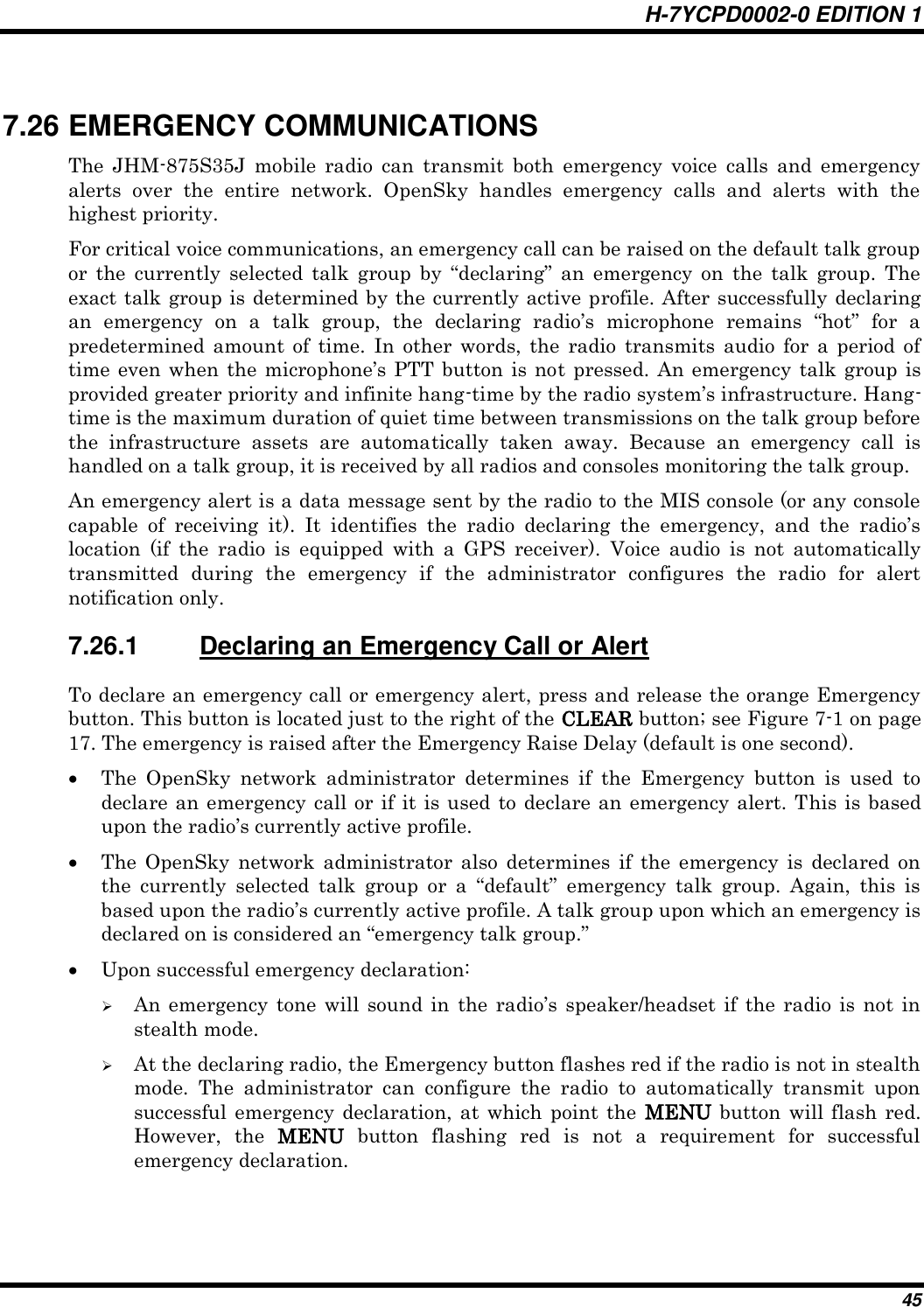
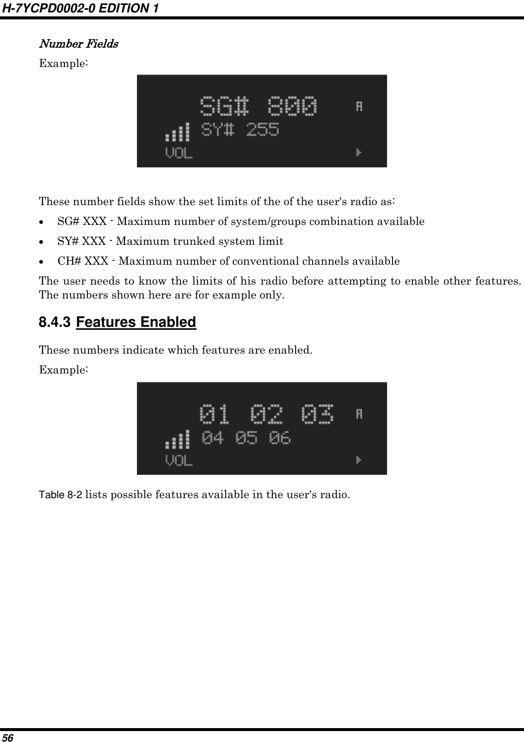
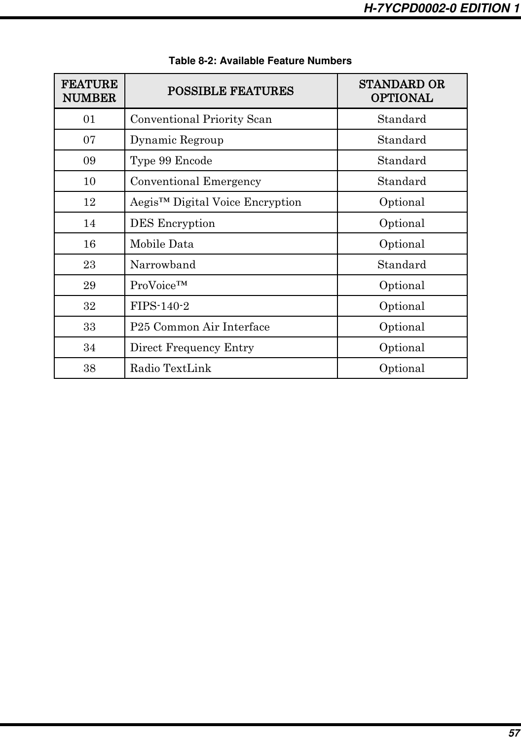
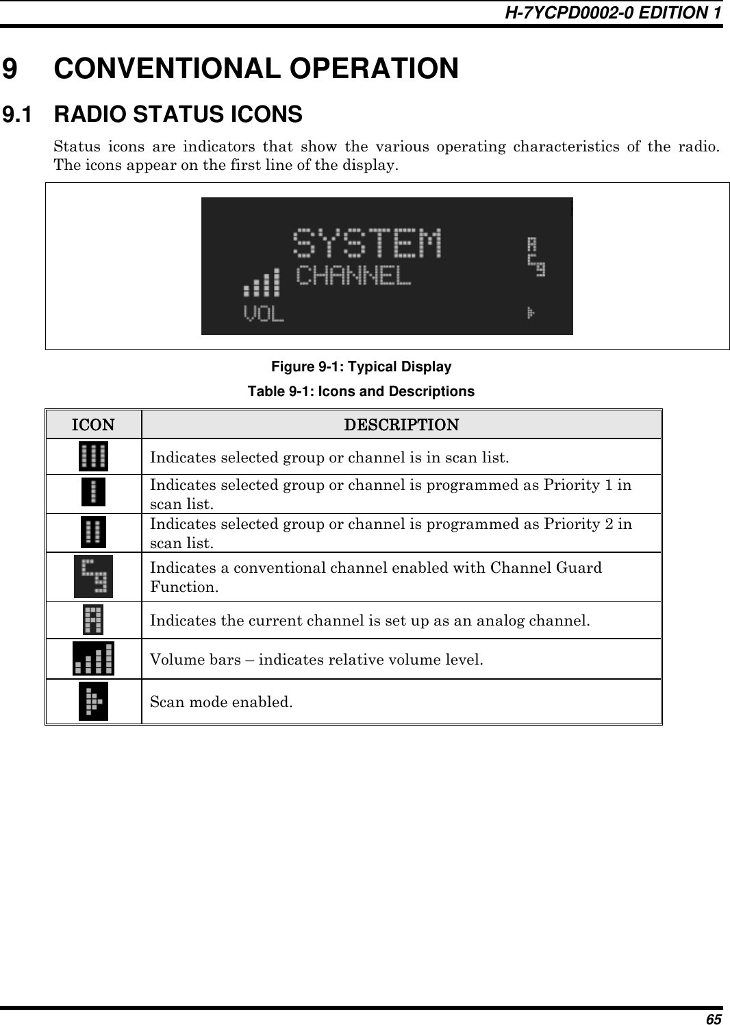
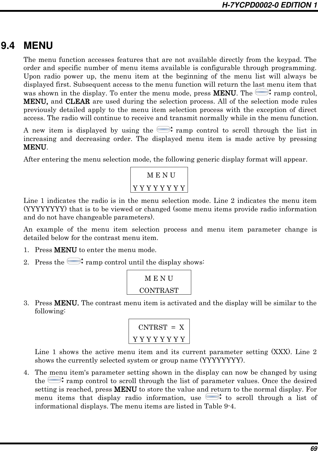
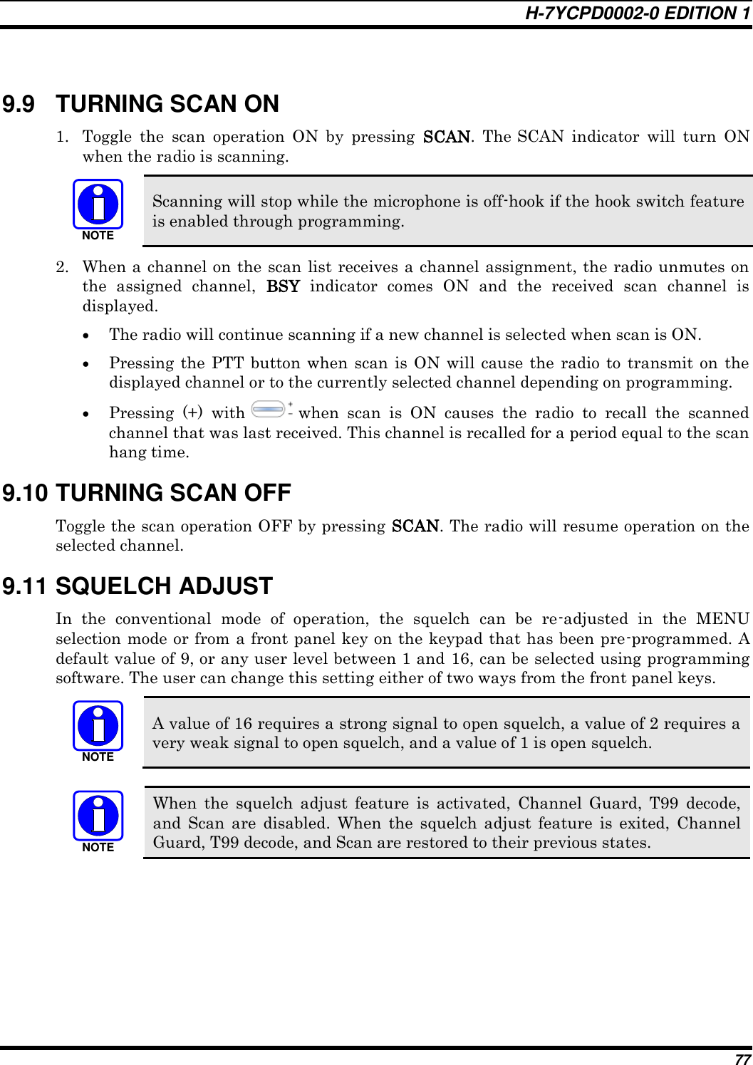
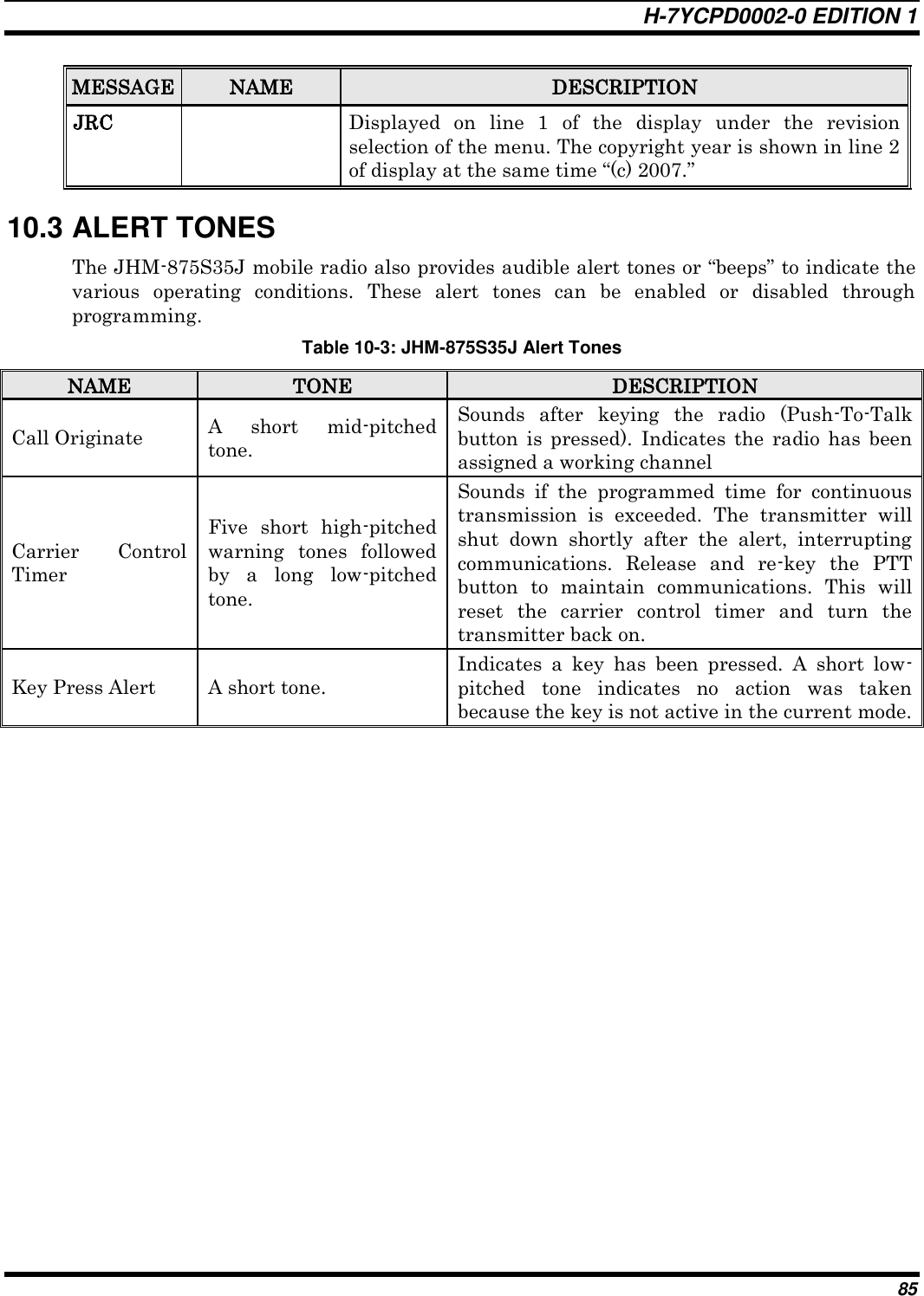
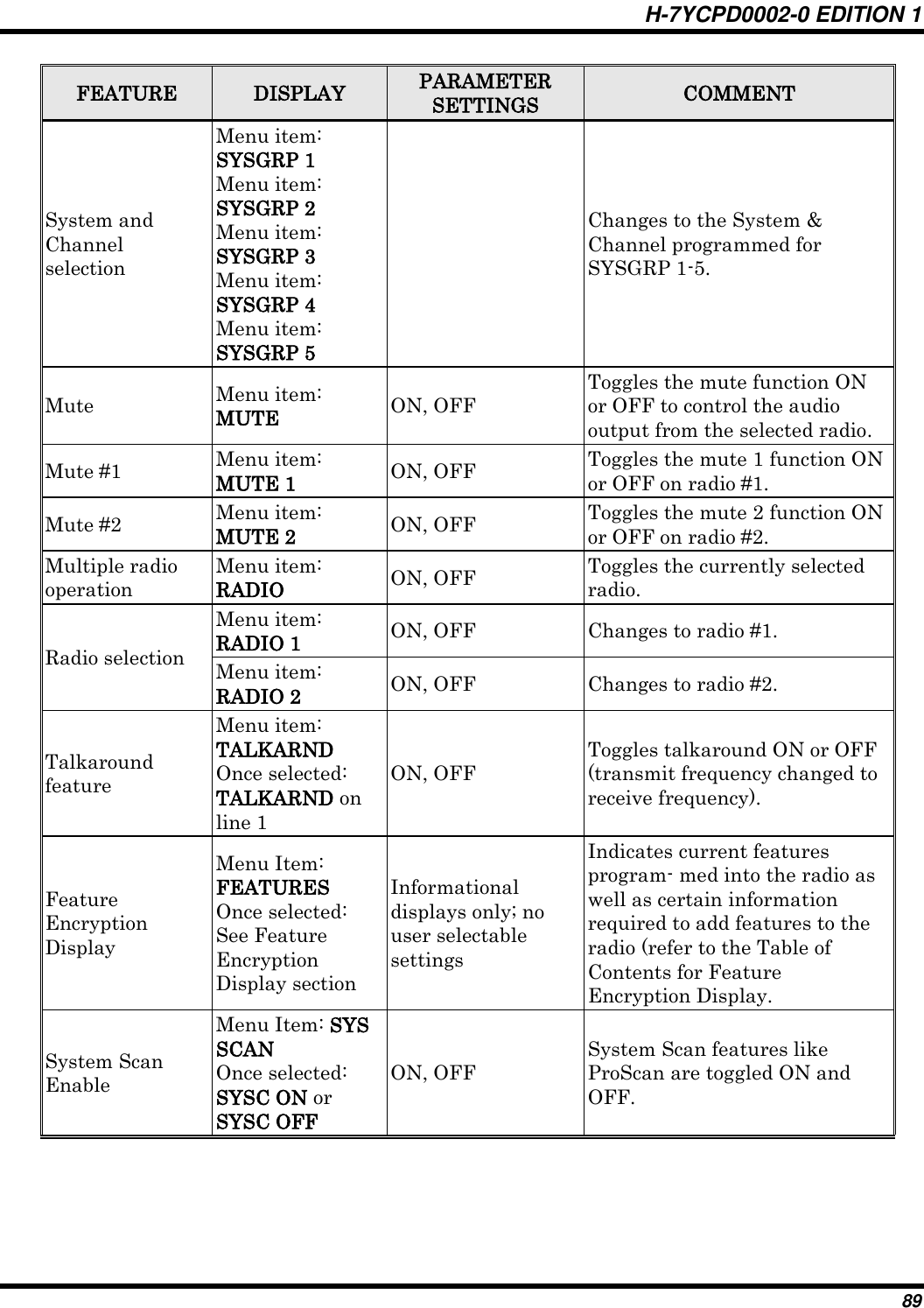
![H-7YCPD0002-0 EDITION 1 49 Presets are saved and restored to/from non-volatile memory. Changing the User ID (login in as a different user) will clear the presets since they are stored on a per-user basis. Changing control heads will not recall presets for the previous control head. NOTE Preset button C can be configured via programming to reboot the radio into a particular application mode. Contact your system administrator to determine if this feature is enabled in your radio. 7.29 DYNAMIC REGROUPING Dynamic regrouping requires that the network administrator determine which radio users should be formed into an impromptu talk group to respond to particular emergency conditions. The administrator will edit the personalities of the affected radios to include an emergency profile and then page the affected radios to re-register with the network to receive their edited personalities. In response, affected radios automatically re-register to receive their edited personalities. During re-registration, subscriber equipment will default to the emergency profile selected by the administrator. 7.30 GPS COORDINATES The radio‟s current latitude and longitude coordinates may be displayed using the “GPS” menu. The following procedure assumes a GPS antenna is connected to the radio and it is receiving adequate signals from GPS satellites: 1. Press until the “GPS” menu appears in the bottom line of the display. Current GPS coordinate latitude and longitude data continuously scrolls in the top line of the display in a degrees:minutes:seconds format. 2. Use to change to another menu. NOTE If the internal GPS receiver‟s data is expired (30 minutes or more) or unavailable, the radio uses the serving base station‟s coordinates [GPS (Site) is displayed]. The GPS Menu will also indicate if the data is aged (2 minutes or more) [GPS (Aged) is displayed]](https://usermanual.wiki/Japan-Radio/875S35J-A/User-Guide-1077261-Page-49.png)

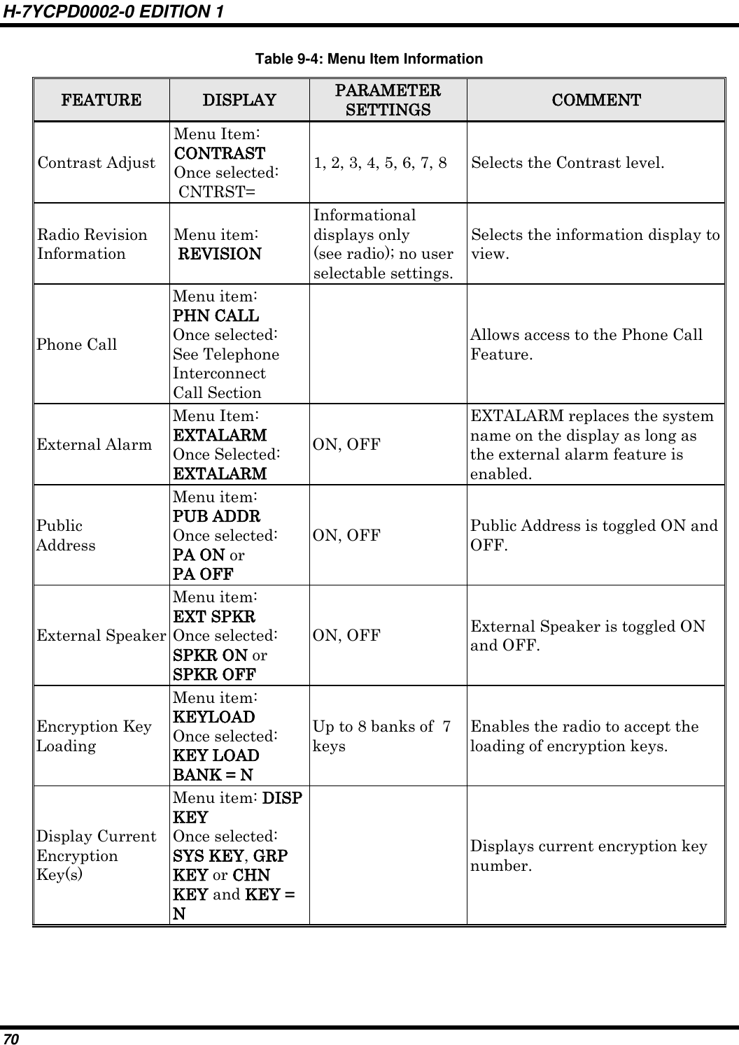
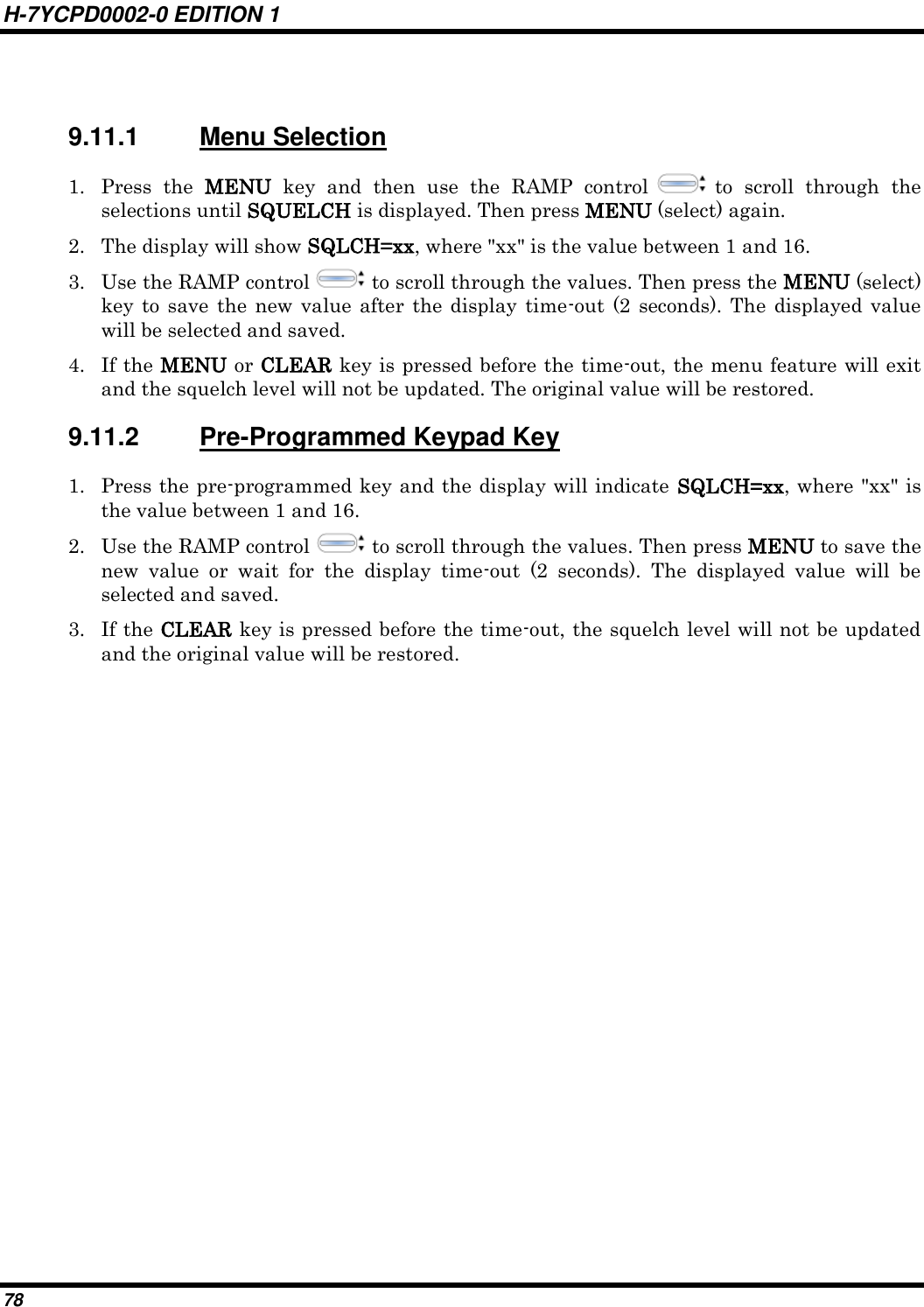
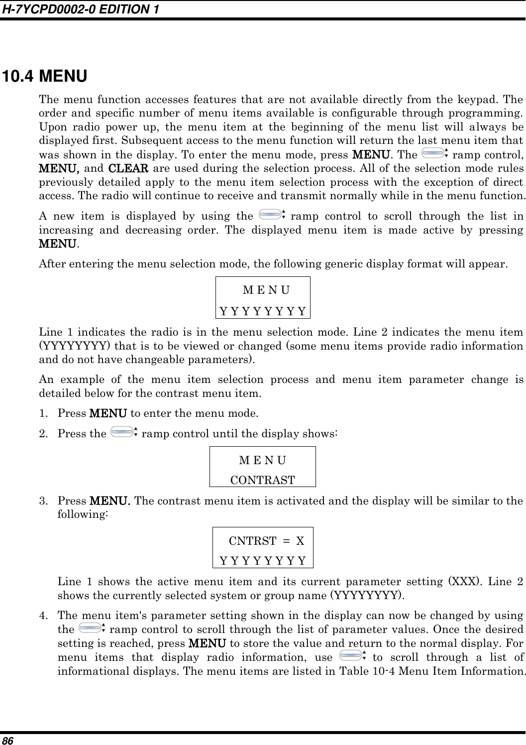
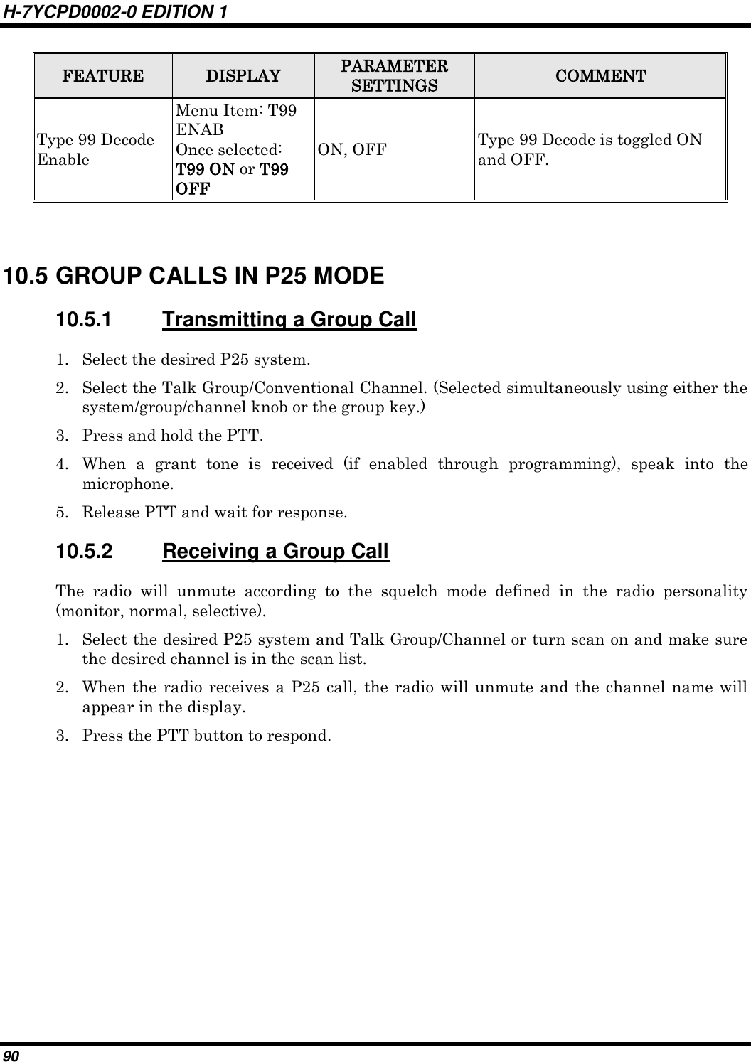


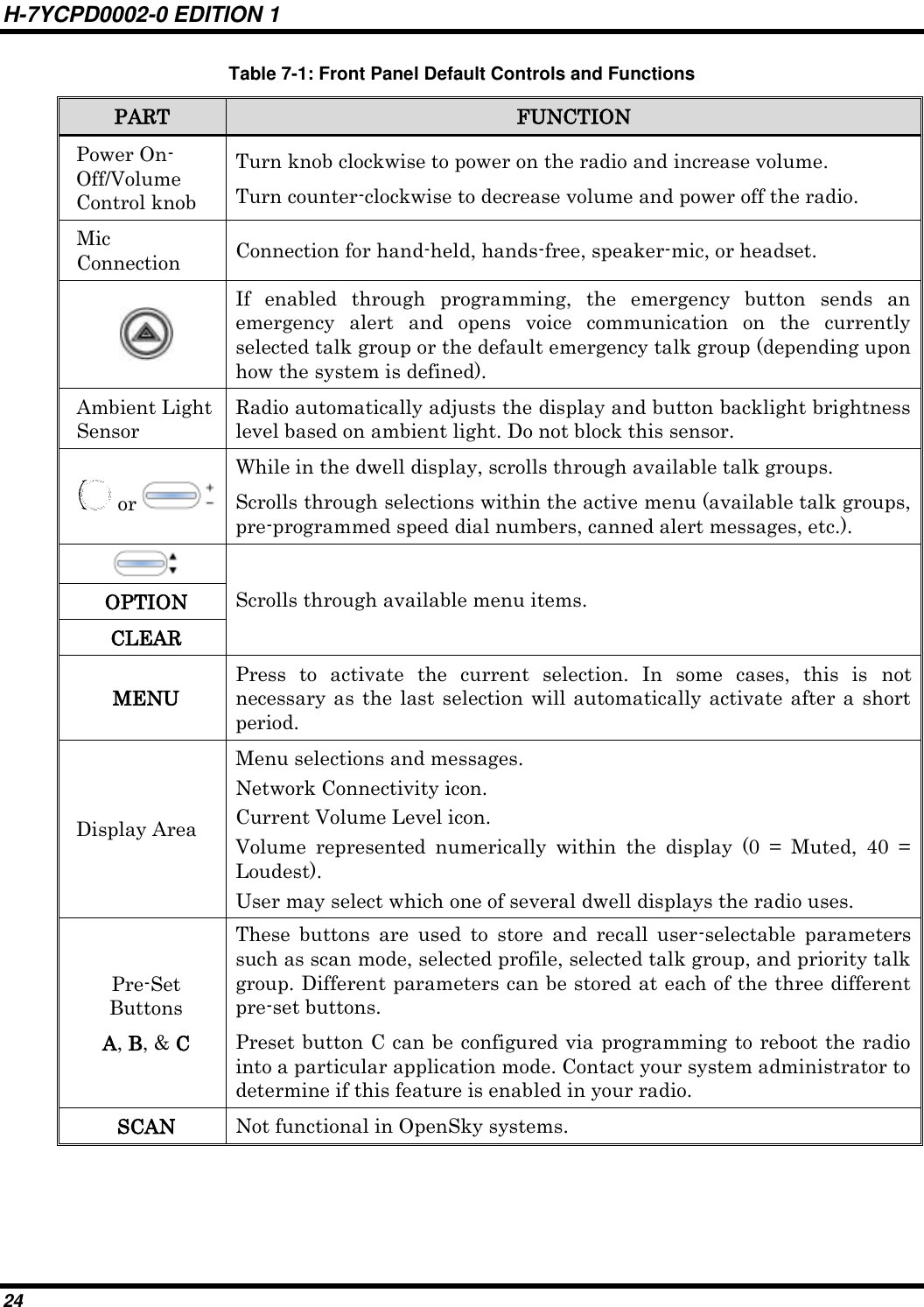
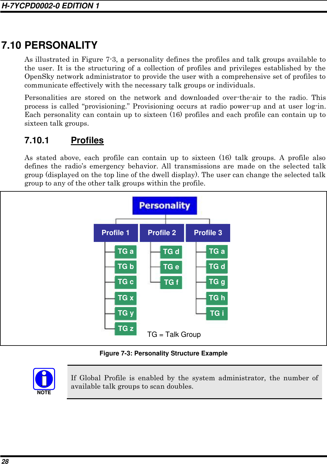
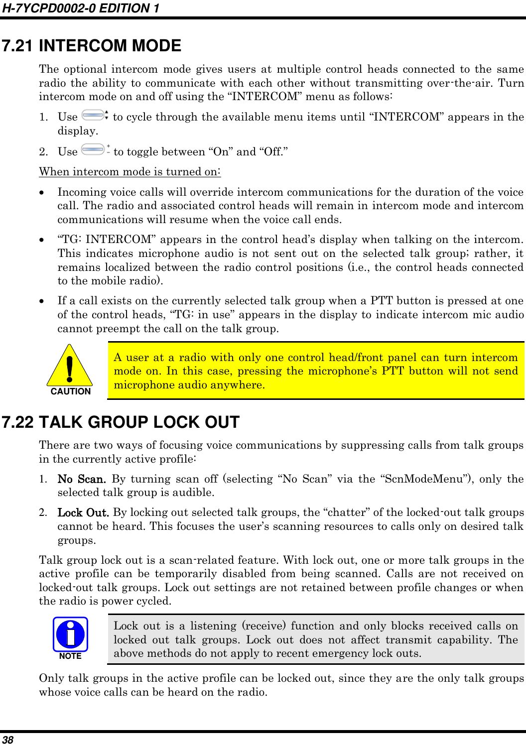
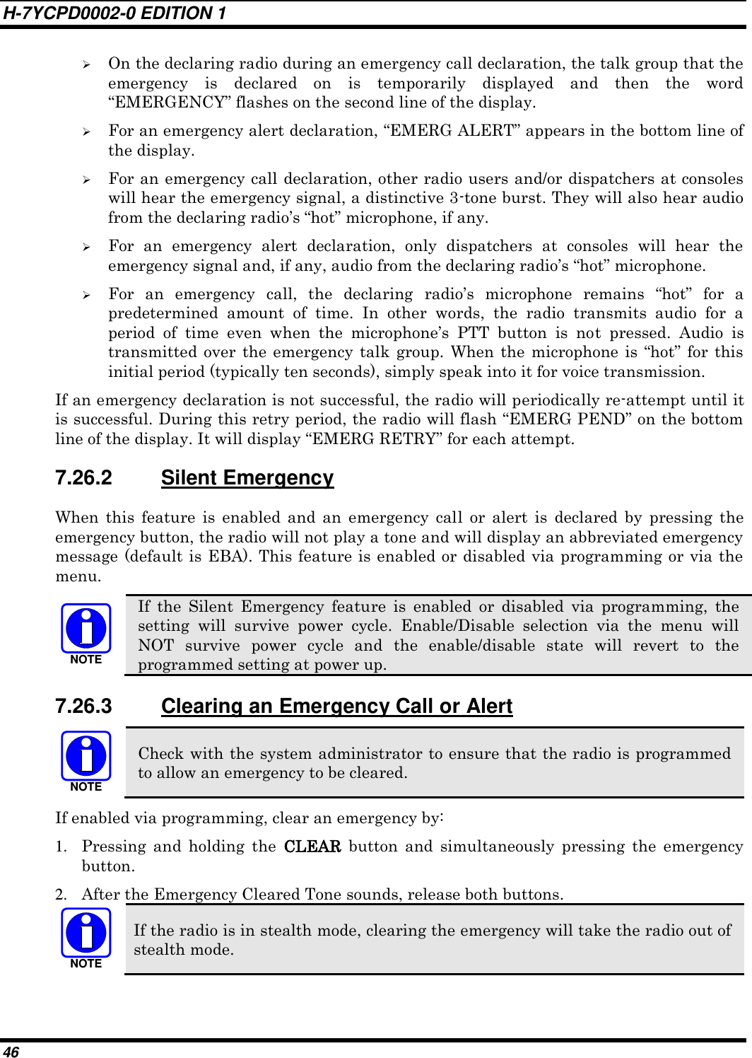
![H-7YCPD0002-0 EDITION 1 103 INDEX [A] Adjusting Audio Treble Level ............................... 44 Adjusting Display and Button Backlight Brightness ............................................................................... 41 Adjusting Side Tone Audio Level ......................... 42 ALERT TONES….…………….…..……36, 95, 112 [B] Basic Menu Structure ............................................. 37 [C] Change operating mode ................................... 27, 42 Changing Scanning Priority ................................... 48 Changing the Active Profile ................................... 39 Checking or Changing Active Scan Mode ............. 47 Checking or Changing the Selected Talk Group ... 39 Clearing an Emergency Call or Alert ..................... 53 [D] Declaring an Emergency Call or Alert ................... 52 Declaring an Emergency Group Call ................... 119 DIRECT MODE OPERATION ........................... 107 Disabling Stealth Mode .......................................... 41 Dismissing an Emergency Call .............................. 54 Dwell Display ........................................................ 33 [E] EMERGENCY OPERATION ............................. 101 Enabling Stealth Mode ........................................... 41 [F] FRONT PANEL COMPONENTS................... 29, 58 [G] Group and Channel Selection ................................ 65 [I] INTERCOM MODE .............................................. 45 [L] Lock Out a Talk Group .......................................... 46 Log off the Network ............................................... 32 LogIn to the Network ............................................. 31 [M] Menu Display and Control Area ............................ 32 [P] PERSONALITY .................................................... 34 Power Up ................................................................ 31 [R] RADIO STATUS ICONS .............. 4, 33, 71, 92, 108 RECEIVING A CALL ......................................... 100 Receiving a Group Call ........................................ 117 Receiving a Selective Call ..................................... 49 Receiving a Voice Call........................................... 43 Receiving an Emergency Call ................................ 54 Receiving an Emergency Group Call ................... 119 Receiving an Encrypted Call .................................. 69 Receiving an Individual Call ................................ 118 Receiving Messages ............................................... 51 REMOTE CONTROL HEAD OPERATION .... 4, 26 [S] SCANNING CONVENTIONAL CHANNELS .. 102 SELF-TEST ........................................................... 31 SENDING A CALL ............................................. 100 Sending Selective Alert Messages ......................... 50 SQUELCH ADJUST ........................................... 104 System Selection .................................................... 65 [T] Terminating a Selective Call .................................. 49 Transmitting a Group Call ................................... 117 Transmitting a Voice Call ...................................... 43 Transmitting an Encrypted Call ............................. 69 Transmitting an Individual Call ........................... 118 TURNING SCAN OFF ........................................ 104 TURNING SCAN ON ......................................... 104 Turning the Radio Off ............................................ 32 TYPE 99 DECODE.............................................. 106 [U] Unlock a Talk Group .............................................. 46 [V] Volume Control ...................................................... 31](https://usermanual.wiki/Japan-Radio/875S35J-A/User-Guide-1077261-Page-103.png)