Japan Radio CMN851 WLAN MODULE User Manual CMN 727A Installation Manual
Japan Radio Co Ltd. WLAN MODULE CMN 727A Installation Manual
Users Manual
1/9
CMN-851 Installation Manual
1. Compliance statement and notification
<FCC / IC>
RF exposure compliance:
This equipment complies with FCC/IC radiation exposure limits set forth for an uncontrolled
environment and meets the FCC radio frequency(RF)Exposure Guidelines in Supplement C to
OET65 and RSS-102 of the IC radio frequency(RF)Exposure rules. This equipment has very low
levels of RF energy that it deemed to comply without maximum permissive exposure evaluation
(MPE). But it is desirable that it should be installed and operated keeping the radiator at least
20cm or more away from person’s body(excluding extremities: hands, wrists, feet and ankles).
< FCC >
NOTE: This equipment has been tested and found to comply with the limits for a Class B digital
device, pursuant to part 15 of the FCC Rules. These limits are designed to provide reasonable
protection against harmful interference in a residential installation. This equipment generates,
uses and can radiate radio frequency energy and, if not installed and used in accordance with the
CAUTION
Changes or modifications not expressly approved by the party responsible for
compliance could void the user’s authority to operate the equipment.
Declaration of Conformity
Product Name: WLAN Module
Model Number: CMN-851
This device complies with Part 15 of FCC Rules and RSS-Gen of IC Rules. Operation is
subject to the following two conditions:
(1) this device may not cause harmful interference, and
(2) this device must accept any interference, including interference that may cause undesired
operation of this device.
2/9
instructions, may cause harmful interference to radio communications. However, there is no
guarantee that interference will not occur in a particular installation. If this equipment does cause
harmful interference to radio or television reception, which can be determined by turning the
equipment off and on, the user is encouraged to try to correct the interference by one or more of the
following measures:
-Reorient or relocate the receiving antenna.
-Increase the separation between the equipment and receiver.
-Connect the equipment into an AC outlet on a circuit different from that to which the receiver is
connected.
-Consult the dealer or an experienced radio/TV technician for help.
In according with 47 CFR Part15.407 (e) U-NII devices operating in 5.15-5.25GHz frequency
bands are restricted to indoor operations only.
This transmitter must not be co-located or operated in conjunction with any other antenna or
transmitter.
This device is slave equipment, the device is not radar detection and not ad-hoc operation in the
DFS band.
End Product Labeling
This transmitter module is authorized only for use in device where the antenna may be installed
such that 20cm may be maintained between the antenna and users. The final end product must
be labeled in a visible area with the following: "Contains FCC ID: CKECMN851”
< IC >
Canada, Industry Canada (IC) Notices
This Class B digital apparatus complies with Canadian ICES-003 and RSS-210.
Operation is subject to the following two conditions: (1) this device may not cause
interference, and (2) this device must accept any interference, including interference
that may cause undesired operation of the device.
Radio Frequency (RF) Exposure Information
The radiated output power of the Wireless Device is below the Industry Canada (IC) radio frequency
exposure limits. The Wireless Device should be used in such a manner such that the potential for
human contact during normal operation is minimized.

3/9
This device has also been evaluated and shown compliant with the IC RF Exposure limits under
mobile exposure conditions. (antennas are greater than 20cm from a person's body).
This device has been certified for use in Canada. Status of the listing in the Industry
Canada’s REL (Radio Equipment List) can be found at the following web address:
http://www.ic.gc.ca/app/sitt/reltel/srch/nwRdSrch.do?lang=eng
Additional Canadian information on RF exposure also can be found at the following web address:
http://www.ic.gc.ca/eic/site/smt-gst.nsf/eng/sf08792.html
Canada, avis d'Industry Canada (IC)
Cet appareil numérique de classe B est conforme aux normes canadiennes ICES-003 et RSS-210.
Son fonctionnement est soumis aux deux conditions suivantes : (1) cet appareil ne doit pas
causer d'interférence et (2) cet appareil doit accepter toute interférence, notamment les
interférences qui peuvent affecter son fonctionnement.
Informations concernant l'exposition aux fréquences radio (RF)
La puissance de sortie émise par l’appareil de sans fil est inférieure à la limite d'exposition aux
fréquences radio d'Industry Canada (IC). Utilisez l’appareil de sans fil de façon à minimiser les
contacts humains lors du fonctionnement normal.
Ce périphérique a également été évalué et démontré conforme aux limites d'exposition aux RF d'IC
dans des conditions d'exposition à des appareils mobiles (les antennes se situent à moins de 20 cm du
corps d'une personne).
Ce périphérique est homologué pour l'utilisation au Canada. Pour consulter l'entrée correspondant à
l’appareil dans la liste d'équipement radio (REL - Radio Equipment List) d'Industry Canada
rendez-vous sur:
http://www.ic.gc.ca/app/sitt/reltel/srch/nwRdSrch.do?lang=eng
Pour des informations supplémentaires concernant l'exposition aux RF au Canada rendez-vous sur :
http://www.ic.gc.ca/eic/site/smt-gst.nsf/eng/sf08792.html
Information to Be Supplied to the End User by the OEM or Integrator
The following regulatory and safety notices must be published in documentation supplied to the
end user of the product or system incorporating an adapter in compliance with local regulations.
Host system must be labeled with "Contains IC: 768B-CMN851 “
4/9
This radio transmitter IC: 768B-CMN851 has been approved by Industry Canada to operate
with the antenna types listed below with the maximum permissible gain and required antenna
impedance for each antenna type indicated. Antenna types not included in this list, having a
gain greater than the maximum gain indicated for that type, are strictly prohibited for use with
this device.
Antenna List
No.
Manufacturer
Part No.
Antenna Type
Peak Gain
1
TAIYO YUDEN
AH 104N2450D1
Chip Antenna
2.1dBi in 2.4GHz
2.4dBi in 5GHz
Note: The Cable (I-pex type) connects WLAN module and Chip antenna.
<R&TTE>
CE Marking:
Please describe the following sentences to the label or the user manual of the product in each
language in the sales country:
Hereby, Japan Radio CO., Ltd. declares that this CMN-851 is in compliance with the
essential requirements and other relevant provisions of Directive 1999/5/EC.

5/9
2. Hardware Specification
2.1 Radio Specification
Table 2-1 Radio Specification
ITEM
Descriptions
Communication Standard
IEEE802.11b/g/n
IEEE802.11a/n
Access Control
CSMA/CA
Frequency Band and
Operating Channels
U.S.A:2412~2462MHz
11 channels(1~11)
Canada:2412~2462MHz
11 channels(1~11)
Europe:2412~2472MHz
13 channels(1~13)
Japan:2412~2472MHz
13 channels(1~13)
U.S.A:5180-5320MHz
5500 – 5700MHz
19 channels
Canada:5180-5320MHz
5500 – 5700MHz
19 channels
Europe:5180-5320MHz
5500 – 5700MHz
19 channels
Japan:5180-5320MHz
5500 – 5700MHz
19 channels
Channel Space
5MHz
20MHz
Modulation
DSSS / OFDM
OFDM
Data Rates Supported
802.11b:1,2,5.5,11Mbps
802.11g:6,9,12,18,24,36
,48,54Mbps
802.11n:HT20/40, MCS0~15
802.11b:1,2,5.5,11Mbps
802.11g:6,9,12,18,24,36
,48,54Mbps
802.11n:HT20/40, MCS0~15
Antenna Connectors
U.FL or equivalent, 2pcs.
2.2 Power Supply
Table 2-2 Power Supply
PARAMETER
MIN
TYP
MAX
UNIT
COMMENTS
Supply Voltage (Vcc)
3.13
3.3
3.47
V
Supply regulated voltage
Operating Current
-
0.74
0.93
A
Condition: Vcc=3.3V
6/9
2.3 Host Interface
2.3.1 Electrical Interface
PCI-express mini-card Rev1.1
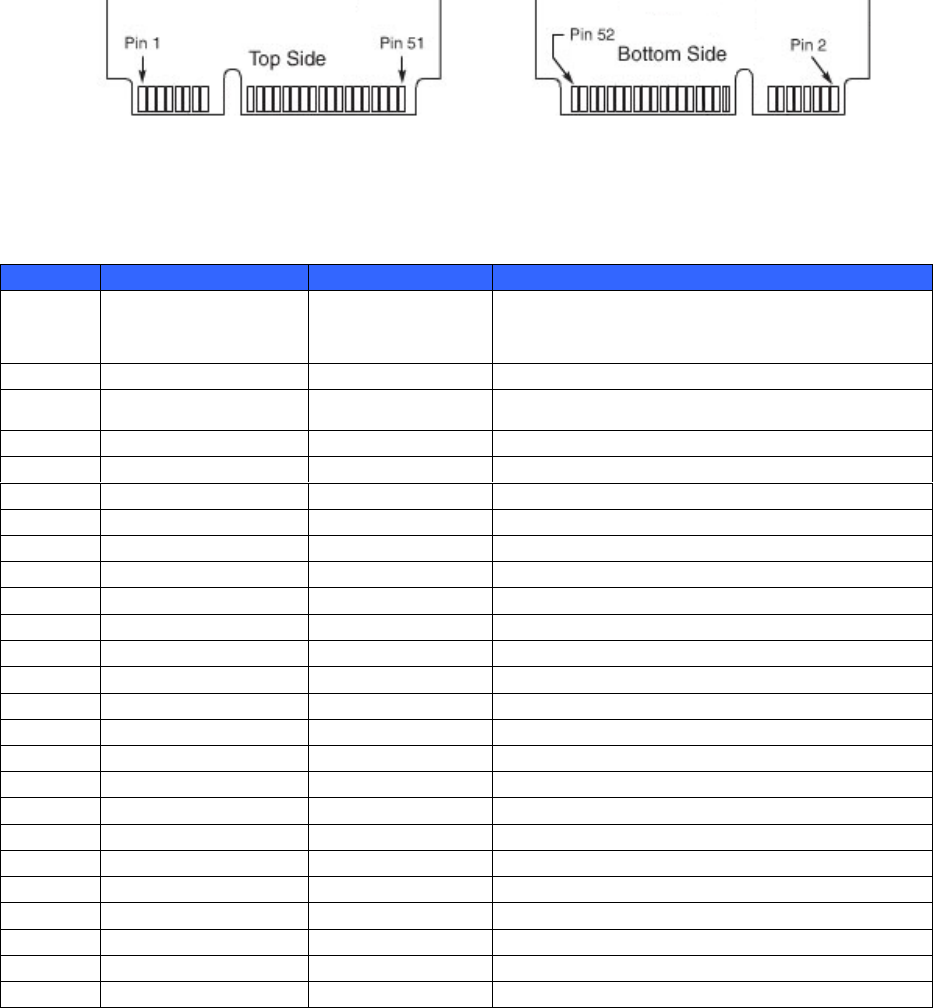
2.3.2 Host Interface connector pin layout
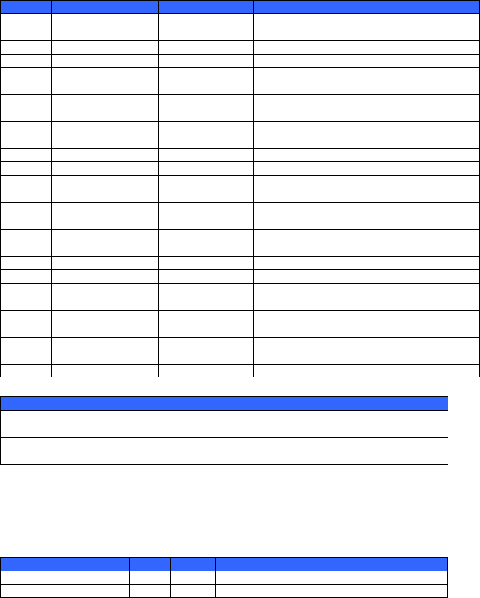
2.3.3 Pin assignment and signal descriptions
Pin No.
Signal name
Signal type
Descriptions
1
#WAKE
OD
-PCIe service a function-initiated wake up
event request
-Open Drain Output
2
3.3Vaux
3
COEX1
I/O
4
GND
5
COEX2
I/O
6
1.5V
NC
7
CLKREQ#
OD
PCIE reference clock request
8
UIM PWR
NC
9
GND
10
UIM_DATA
NC
11
REFCLK-
I
PCIE differential reference clock(100MHz)
12
UIM_CLK
NC
13
REFCLK+
I
PCIE differential reference clock (100MHz)
14
UIM_RESET
NC
15
GND
16
UIM_VPP
NC
17
Reserved UIM_C8)
NC
18
GND
19
Reserved UIM_C4)
NC
20
W_DISABLE#
IH/OH
21
GND
22
RESET#
IH
PCIE reset
23
PERn0
O
PCIE Differential transmit
24
3.3Vaux
25
PERp0
O
PCIE Differential transmit
Fig.1 Host Interface Connector pin layout
7/9
Pin No.
Signal name
Signal type
Descriptions
26
GND
27
GND
GND
28
+1.5V
NC
29
GND
GND
30
SMB_CLK
NC
31
PETn0
I
PCIE Differential receive
32
SMB_DATA
NC
33
PETp0
PCIE Differential receive
34
GND
GND
35
GND
NC
36
USB D-
NC
37
GND
GND
38
USB D+
NC
39
3.3Vaux
40
GND
GND
41
3.3Vaux
42
LED_WWAN#
NC
43
GND
44
LED_WLAN#
IH/OH
45
Reserved
NC
46
LED_WPAN#
NC
47
Reserved
NC
48
+1.5V
NC
49
Reserved
NC
50
GND
GND
51
Reserved
NC
52
3.3Vaux
Signal type
Description
I
Input
O
Output
OD
Open Drain
H
Pull up
2.4 Environmental Conditions
ITEM
MIN
TYP
MAX
UNIT
COMMENTS
Operating Temperature
0
+50
degC
Operating Humidity
20
95
%Rh
Non condensing
8/9
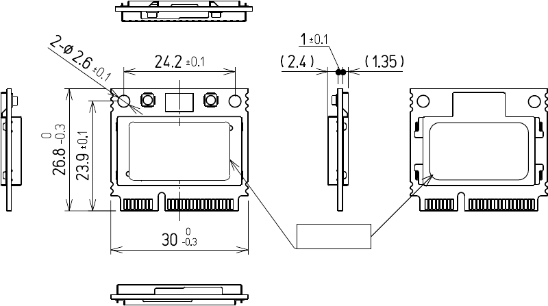
2.5 Mechanical Specification
Size : 30(W)x26.8(D)x4.75(H)mm
Weight : Approx. 5g
Fig.2- Outline Drawing
Label
9/9
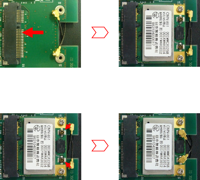
3. Installation
(1) Please insert the module in the host side connector firmly.
(2) Please connect the antenna cables with ANT-A and ANT-B
insert the module