Japan Radio CMN851A Wireless LAN Module User Manual CMN 851A Manual 130617
Japan Radio Co Ltd. Wireless LAN Module CMN 851A Manual 130617
UserManual.wiki
>
Japan Radio
>
CMN851A User Manual
(Short term Confidential) Users Manual
Navigation menu
Upload a User Manual
Namespaces
Wiki Guide
HTML
PDF
Info
Views
User Manual
Discussion / Help
Navigation

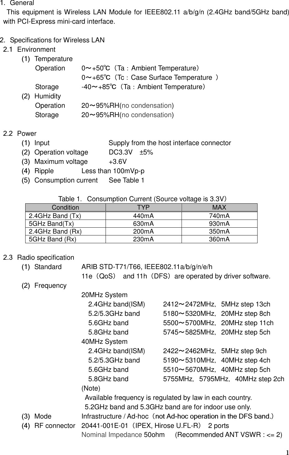
![4 (4) Receiver sensitivity Table 6.2.4GHz band System Band width MCS index Data Rate Sensitivity [dBm] 802.11b (2.4GHz band) 1Mbit/s Less than -80 2Mbit/s Less than -75 802.11g (2.4GHz band) 20MHz 6Mbit/s Less than -82 9Mbit/s Less than -81 12Mbit/s Less than -79 18Mbit/s Less than -77 24Mbit/s Less than -74 36Mbit/s Less than -70 48Mbit/s Less than -66 54Mbit/s Less than -65 802.11n (2.4GHz band) 20MHz 0 8 Less than -82 1 9 Less than -79 2 10 Less than -77 3 11 Less than -74 4 12 Less than -70 5 13 Less than -66 6 14 Less than -65 7 15 Less than -64 40MHz 0 8 Less than -79 1 9 Less than -76 2 10 Less than -74 3 11 Less than -71 4 12 Less than -67 5 13 Less than -63 6 14 Less than -62 7 15 Less than -61](https://usermanual.wiki/Japan-Radio/CMN851A/User-Guide-1993132-Page-7.png)
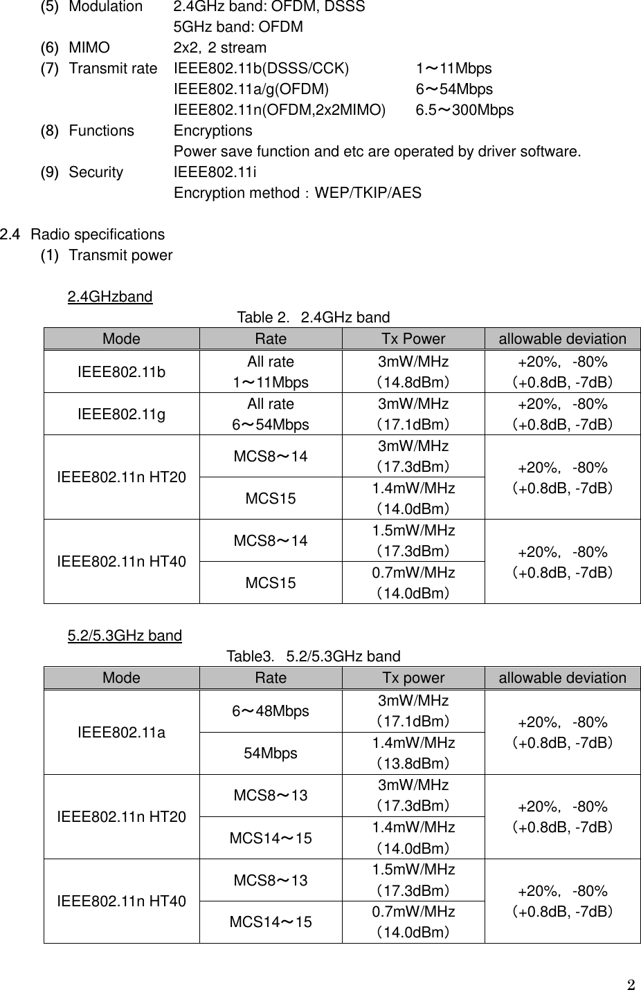
![5 Table 7.5GHz band System Band width MCS index Data Rate Sensitivity [dBm] 802.11a (5GHz band) 20MHz 6Mbit/s Less than -82 9Mbit/s Less than -81 12Mbit/s Less than -79 18Mbit/s Less than -77 24Mbit/s Less than -74 36Mbit/s Less than -70 48Mbit/s Less than -66 54Mbit/s Less than -65 802.11n (5GHz band) 20MHz 0 8 Less than -82 1 9 Less than -79 2 10 Less than -77 3 11 Less than -74 4 12 Less than -70 5 13 Less than -66 6 14 Less than -65 7 15 Less than -64 40MHz 0 8 Less than -79 1 9 Less than -76 2 10 Less than -74 3 11 Less than -71 4 12 Less than -67 5 13 Less than -63 6 14 Less than -62 7 15 Less than -61](https://usermanual.wiki/Japan-Radio/CMN851A/User-Guide-1993132-Page-8.png)