Japan Radio JHS-183 MARINE AIS CLASS A User Manual E a
Japan Radio Co Ltd. MARINE AIS CLASS A E a
Contents
- 1. User Manual 2
- 2. User Manual 1
User Manual 1

Automatic Identification System
JHS-183
Instruction Manual
7ZPJD0553

i
Preface
Thank you for purchasing the JHS-183 Automatic Identification System (AIS).
The JHS-183 is a Class A shipborne AIS equipment that communicates ship's static data and ship's
dynamic data with other vessels or coast stations on VHF channels using TDMA techniques.
x Be sure to read this manual before using the equipment.
x Keep this manual near at hand for quick reference.
ii
㪮㪘㪩㪥㪠㪥㪞㩷
Before Operation
Concerning the symbols
This manual uses the following symbols to explain correct operation and to prevent injury or
damage to property.
The symbols and descriptions are as follows. Understand them before proceeding with this
manual.
Indicates a warning that, if ignored, may
result in serious injury or even death.
Indicates a caution that, if ignored, may
result in injury or damage to property.
Examples of symbols
The ٌ symbol indicates caution (including DANGER and WARNING).
The illustration inside the ٌ symbol specifies the content of the caution more
accurately. (This example warns of possible electrical shock.)
The symbol indicates that performing an action is prohibited.
The illustration inside the symbol specifies the contents of the prohibited
operation. (In this example disassembly is prohibited.)
The ٨ symbol indicates operations that must be performed.
The illustration inside the ٨ symbol specifies obligatory instructions. (In this
example unplugging is the obligatory instruction.)
Concerning warning labels
A warning label is pasted to the top cover of this product.
Do not remove, damage or modify the label.
㪚㪘㪬㪫㪠㪦㪥㩷
iii
㪮㪘㪩㪥㪠㪥㪞㩷
Handling Precautions
Do not disassemble or customize this unit. Doing so may cause fire,
electrical shock or malfunction.
Do not use a voltage other than specified. Doing so may cause fire,
electrical shock or malfunction.
Do not attempt to check or repair the interior of this equipment by
non-qualified service personnel, as doing so may cause fire, electric shock
or malfunction. If any malfunctions are detected, contact our service center
or agents.
iv
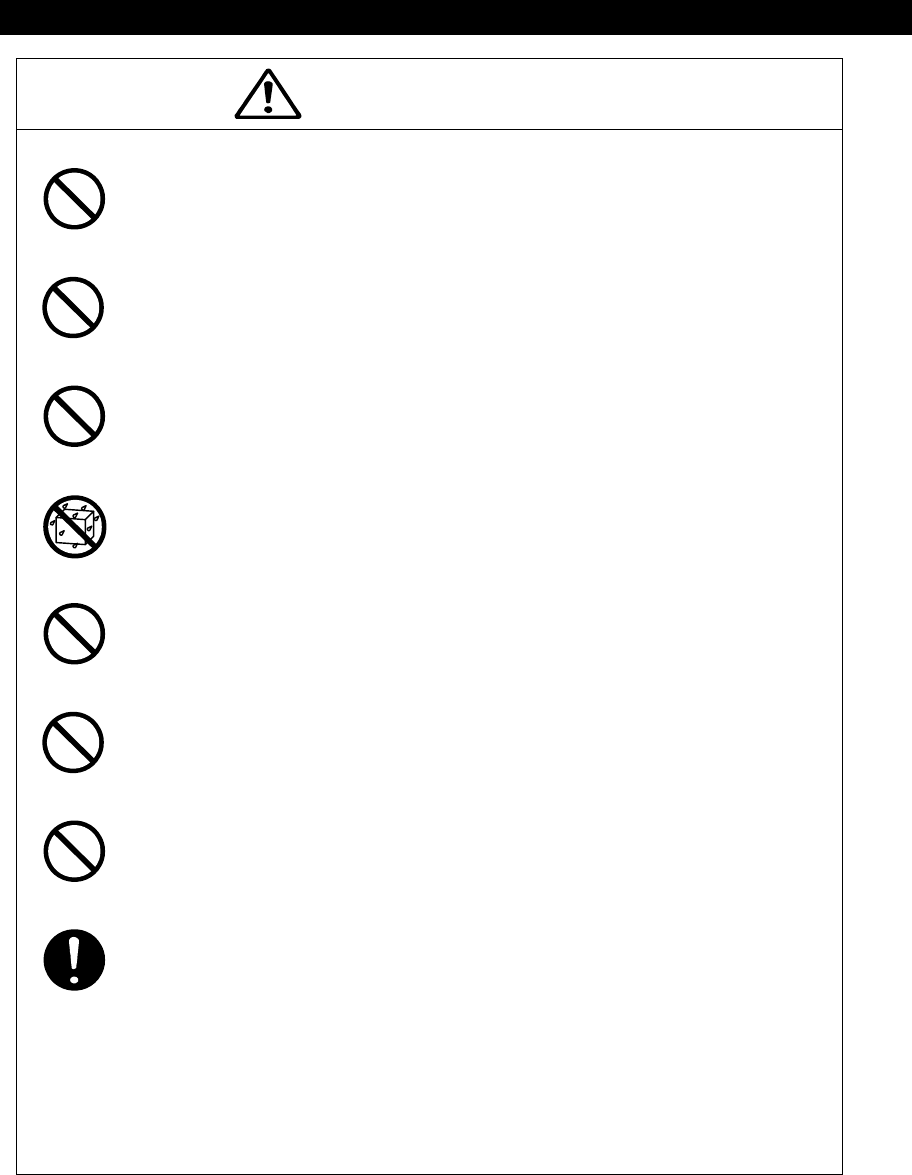
㪚㪘㪬㪫㪠㪦㪥㩷
Do not use this equipment for anything other than specified.
Doing so may cause malfunction or damage to persons.
Do not adjust the trimmer resistors or the trimmer capacitors on the PCB
unit, except when and if they need to be adjusted.
Doing so may cause malfunction or damage to persons. They are preset at
the factory.
Do not install this equipment in a place other than specified or in one with
excessive humidity, steam, dust or soot. Doing so may cause fire, electric
shock, malfunction or damage to persons.
Do not get this equipment wet or spill any liquids on or near this equipment.
Doing so may cause electrical shock or malfunction.
Do not place this equipment anywhere vibration or impact is likely to occur.
Doing so may cause a fall or damage to property and persons.
Do not place anything on this equipment.
Doing so may cause a fall, malfunction or damage to property and persons.
Leave installation of this equipment to our service center or agents.
Installation by an unauthorized person may happen to malfunction.
Use this AIS equipment only as assisting device for collision avoidance.
Also, the officer should make the final decision to maneuver by himself.
v
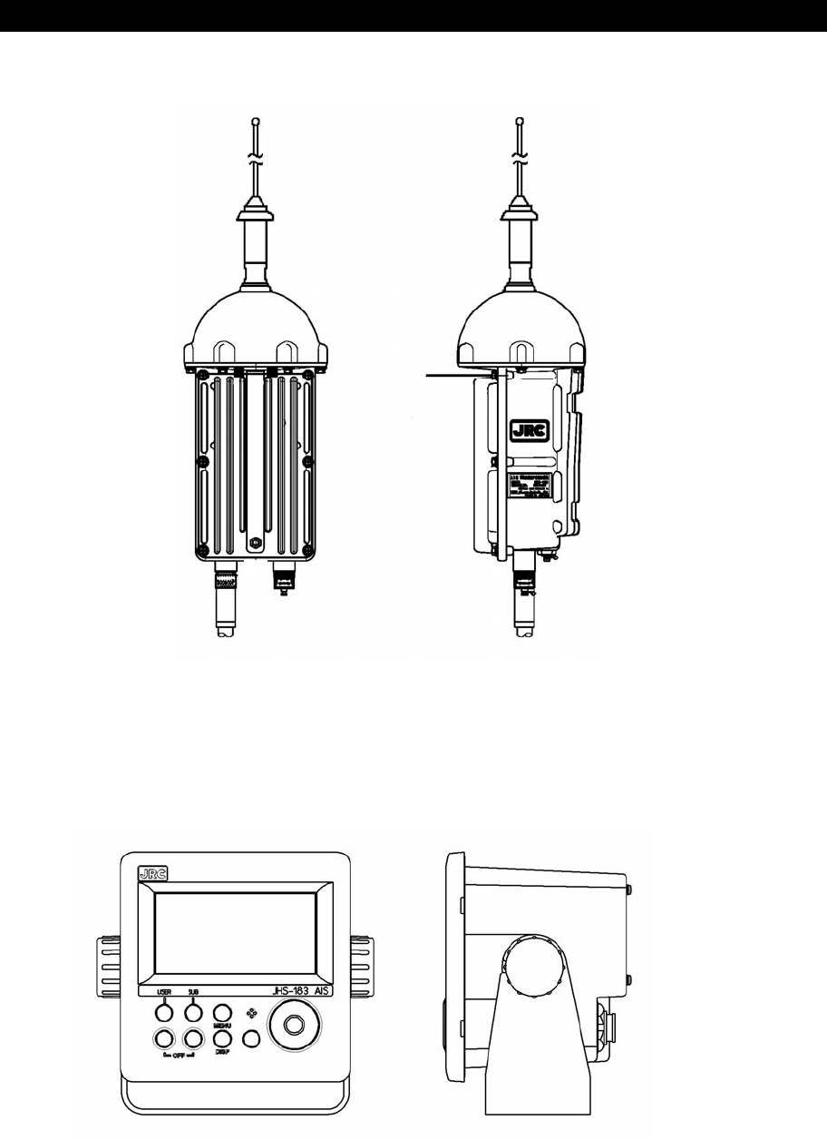
External Views
NTE-183 AIS Transponder
NCM-983 AIS Controller
vi
Optional equipment
NQE-5183 Connection Box
NBD-577C Power Supply Unit

vii
CONTENTS
Preface ............................................................................................................... γ
Before Operation ................................................................................................. δ
Handling Precaution ............................................................................................ ε
External Views .................................................................................................... η
1. GENERAL ..................................................................................................... 1-1
1.1 Outlines ....................................................................................................... 1-1
1.2 Features ...................................................................................................... 1-1
1.3 Components ................................................................................................ 1-2
1.3.1 Standard Components ............................................................................. 1-2
1.3.2 Options .................................................................................................... 1-2
1.3.3 Configuration ............................................................................................ 1-3
1.4 Outline ........................................................................................................ 1-4
2. INSTALLATION DIAGRAM ........................................................................... 2-1
3. PART NAMES AND FUNCTIONS ................................................................. 3-1
3.1 NCM-983 AIS Controller ............................................................................. 3-1
4. DISPLAYS ..................................................................................................... 4-1
5. OPERATION ................................................................................................. 5-1
5.1 Menu Tree ................................................................................................... 5-1
5.2 Basic Operation .......................................................................................... 5-2
5.2.1 Turning ON the power................................................................................ 5-2
5.2.1.1 Other Ships List ...................................................................................... 5-4
5.2.1.2 Other Ship’s Detail Information ............................................................... 5-5
5.2.1.3 Own Ship’s Detail Information................................................................. 5-6
5.2.1.4 Display Setup of Other Ships List ......................................................... 5-10
5.2.1.5 Graphic Display ..................................................................................... 5-11
5.2.2 Turning OFF the Power ............................................................................ 5-11
5.2.3 Alarm ....................................................................................................... 5-12
5.2.3.1 Guard Zone Alarm ................................................................................ 5-12
5.2.4 Character Pad Window Display and Input Method ................................. 5-13
5.2.5 Numerical Input........................................................................................ 5-14
5.3 Main Menu ................................................................................................ 5-15
5.3.1 Voyage Data Setting .............................................................................. 5-16
5.3.1.1 Navigational Status ............................................................................... 5-17
5.3.1.2 Destination Input................................................................................... 5-18
5.3.1.3 Estimated Time of Arrival (ETA) Input ................................................... 5-18
5.3.1.4 Draught Value Input .............................................................................. 5-19
5.3.1.5 Cargo Type Selection............................................................................ 5-19
5.3.1.6 Persons on Board Input ........................................................................ 5-20
5.3.1.7 Re-load Destination from history Data .................................................. 5-21
5.3.2 Message Menu ........................................................................................ 5-22
5.3.2.1 Editing / Sending Messages ................................................................. 5-23
5.3.2.2 TX Tray (Viewing Transmitted Messages) ............................................ 5-28
5.3.2.3 RX Tray (Viewing Received Messages)................................................ 5-30
5.3.2.4 Interrogation.......................................................................................... 5-32

viii
5.3.2.5 Long Range Messages......................................................................... 5-34
5.3.3 Maintenance ............................................................................................ 5-36
5.3.3.1 Self Diagnosis ..................................................................................... 5-37
5.3.3.2 Communication Test ............................................................................. 5-40
5.3.3.3 AIS Alarm.............................................................................................. 5-41
5.3.3.4 Sensor Status ...................................................................................... 5-43
5.3.3.5 Event Log.............................................................................................. 5-44
5.3.3.6 Software Version................................................................................... 5-44
5.3.4 Set up Menu ............................................................................................ 5-45
5.3.4.1 Display Setting of Date and Time (DATE&TIME) .................................. 5-46
5.3.4.2 My Controller ........................................................................................ 5-47
5.3.4.3 Regional Channel ................................................................................. 5-51
5.3.4.4 Power Reduction .................................................................................. 5-56
5.3.4.5 Registration of Group Ships (GROUP SHIP) ........................................ 5-56
5.3.4.6 Change of Channels and Transmission Power (CHANNEL/POWER) .. 5-58
5.3.4.7 Change Password (PASSWORD) ........................................................ 5-59
5.3.4.8 Display Style of Latitude and Longitude (POSN DISP SET) ................. 5-60
5.3.4.9 Indication of AIS SART test signal (SART TEST SET).......................... 5-60
5.3.4.10 Long-Range Set.................................................................................. 5-60
5.3.4.11 Prohibition of Transmission (SILENT MODE) ..................................... 5-62
5.3.4.12 CCRP set............................................................................................ 5-62
5.3.4.13 Initial Setting of Own Ship’s Heading Direction (NSK UNIT)............... 5-63
5.4 Explanation of Graphic display ................................................................... 5-65
5.4.1 The Outline of Display ............................................................................. 5-65
5.4.2 Operation for Graphic display .................................................................. 5-65
5.4.3 Setting the Contents of Display................................................................ 5-66
5.4.3.1 Display the Setting Screen.................................................................... 5-66
5.4.3.2 Display Item Explanation ...................................................................... 5-66
5.4.3.3 Display.................................................................................................. 5-68
5.4.4 Selection of Other Ships ........................................................................ 5-69
5.4.5 Auto Range Setting.................................................................................. 5-69
6. MAINTENANCE AND INSPECTION ............................................................. 6-1
6.1 General Maintenance and Inspection ......................................................... 6-1
6.2 Periodic Inspection ...................................................................................... 6-2
6.2.1 Confirming the Own Ship's Information...................................................... 6-2
6.2.2 Confirming the TRX Channel..................................................................... 6-3
6.2.3 Confirming the Alarm Status ...................................................................... 6-3
6.2.4 Confirming the Conditions of the Sensors ................................................. 6-6
6.3 Trouble Shootings......................................................................................... 6-7
6.3.1 Trouble Shootings...................................................................................... 6-7
6.3.2 Maintenance Units ................................................................................... 6-10
6.3.3 Spare parts for periodic maintenance ...................................................... 6-10
7. AFTER-SALES SERVICE ............................................................................. 7-1
Warranty .......................................................................................................... 7-1
Holding period of Spare parts............................................................................ 7-1
Before returning to repair ................................................................................ 7-1
Periodical maintenance recommended ........................................................... 7-1

ix
8. SPECIFICATIONS ........................................................................................ 8-1
8.1 General (JHS-183) ...................................................................................... 8-1
8.2 AIS Transponder (NTE-183) ....................................................................... 8-1
8.2.1 TRX port .................................................................................................... 8-1
8.2.2 Environmental condition ........................................................................... 8-1
8.3 AIS Controller (NCM-983) ........................................................................... 8-2
8.3.1 Operation panel ....................................................................................... 8-2
8.3.2 Environmental condition ........................................................................... 8-2
8.3.3 External interfaces ................................................................................... 8-2
8.3.4 Transmission intervals ............................................................................. 8-2
8.3.5 Supported interface sentences .................................................................. 8-3
8.4 Connection Box (NQE-5183) .................................................................... 8-13
8.4.1 Environmental condition ......................................................................... 8-13
8.4.2 External interfaces ................................................................................. 8-13
8.5 AC Power Supply Unit (NBD-577C - Option) ............................................ 8-13

x

1-1
1. GENERAL
1.1 Outlines
Automatic Identification System (AIS) is a maritime navigation and radio communication system. This
system intends to enhance the safety of life at sea, the safety and efficiency of navigation and the
protection of the marine environment by communicating navigational information automatically on VHF
channels between ship to ship and ship to shore.
JHS-183 meets the requirements of the SOLAS Conventions for the Class A shipborne equipment of
the universal AIS. JHS-183 mainly consists of AIS Transponder, Connection Box and AIS Controller.
The combined antenna and transponder design allows installation at any convenient location on any
vessels. The small and simple design controller allows easy installation and operation. JHS-183
employs the latest technologies such as digital signal processing, circuit integration technology,
complies ensure high performance and high reliability.
1.2 Features
٨ Fully
Complies with International Regulations
֤֤֤֤֤֤֤֤֤֤֤֤֤֤֤֤֤֤֤֤֤֤֤֤֤֤֤֤֤֤֤֤֤֤֤֤֤֤֤֤֤֤֤
JHS-183 is designed to meet the requirements of the SOLAS Conventions for the Class A shipborne
equipment of the universal AIS and fully complies with international regulations: IMO MSC74(69) Annex
3, ITU-R M.1371, IEC61993-2, IEC60945 etc.
٨ Combined Antenna and Transponder for Ease of Installation
֤֤֤֤֤֤֤֤֤֤֤֤֤֤֤֤֤֤֤֤֤֤֤֤֤֤֤֤֤֤֤֤֤֤֤֤֤֤֤֤֤֤֤
JHS-183 employs the combined antenna and transponder design. This design allows installation at any
convenient location on any vessels. For the connection between above deck component and below
deck component, only one cable is needed.
٨
Increased Probability of Vessel Detection
֤֤֤֤֤֤֤֤֤֤֤֤֤֤֤֤֤֤֤֤֤֤֤֤֤֤֤֤֤֤֤֤֤֤֤֤֤֤֤֤֤֤֤
JHS-183 is equipped with a guard zone alert function. When preset guard zone range and other vessel
enters into the zone, JHS-183 indicates and sounds the alert. This function enhances probability of
vessel detection.
٨
Recognition of Own-group Vessels
֤֤֤֤֤֤֤֤֤֤֤֤֤֤֤֤֤֤֤֤֤֤֤֤֤֤֤֤֤֤֤֤֤֤֤֤֤֤֤֤֤֤֤
JHS-183 is equipped with a recognition of own-group vessels function. When preset own-group vessels’
identification in advance, the display indicates the own-group vessel sign. This sign allows easy
recognition of own-group vessels.
٨
Self-diagnosis Function
֤֤֤֤֤֤֤֤֤֤֤֤֤֤֤֤֤֤֤֤֤֤֤֤֤֤֤֤֤֤֤֤֤֤֤֤֤֤֤֤֤֤֤
JHS-183 is equipped with a built-in automatic self-diagnosis function. This function allows easy
maintenance and high system reliability.
٨
System Integration Availability
֤֤֤֤֤֤֤֤֤֤֤֤֤֤֤֤֤֤֤֤֤֤֤֤֤֤֤֤֤֤֤֤֤֤֤֤֤֤֤֤֤֤֤
JHS-183 is equipped with various interfaces. These interfaces allow system integration and future
expansions.
1-2
1.3 Components
1. 3. 1 Standard Components
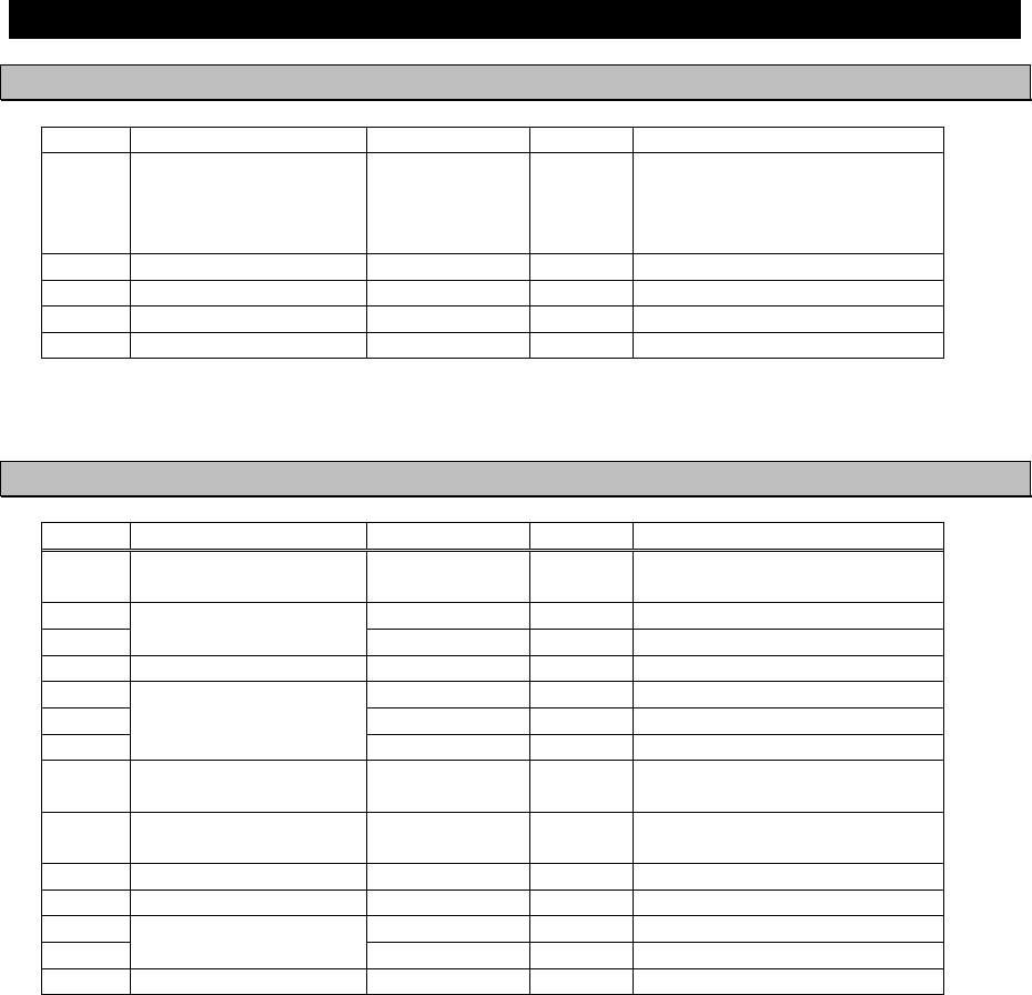
No. Description Model Qty Notes
1 AIS Transponder NTE-183 1
With 1 whip antenna,
2 fitting bands
1 connector N-P-10U
2 Rubbers 10 x 10 x 10
2 AIS Controller NCM-983 1 With 4 tapping screws
3 Control cable CFQ-9183A 1 Length=2m
4 Spare parts 7ZXJD0136 1
5 Instruction manual 7ZPJD0553 1 English
1. 3. 2 Options
No. Description Model Qty Notes
1 AC/DC Power supply
unit NBD-577C 1 100/220V Manual Change
2 CFQ-9183D 1 Length=10m
3
Control cable for
NCM-983 CFQ-9183F 1 Length=20m
4 Connection box NQE-5183 1 With 4 tapping screws
5 CFQ-9193A 1 Length=2m
6 CFQ-9193D 1 Length=10m
7
Data cable for
NQE-5183 CFQ-9193F 1 Length=20m
8 AC power supply unit
for Pilot PC NBG-380 1 120Vac output
9 Pilot plug cable CFQ-9173A 1 Wall mount cable
Length=0.3m
10 Pilot plug cable CFQ-6961 1 Length=20m
11 Pilot plug box NQE-3150 1 Wall mount type
12 MPBX40498 1 Color: 7.5BG7/2
13
Console mounting kit
for NQE-3150 MPBX45388 1 Color: N4.0
14 L-type adapter CFQ-9184 1
1-3
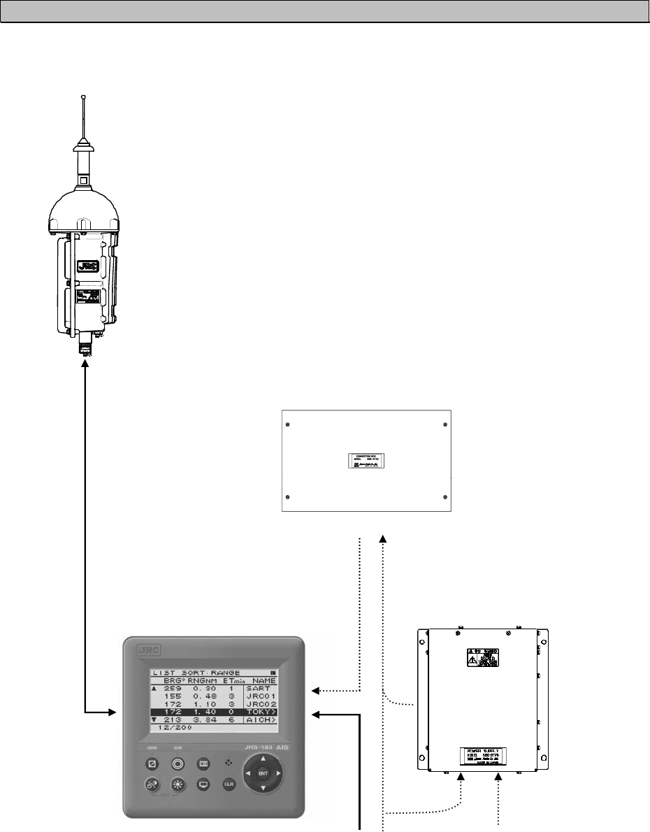
1. 3. 3 Configuration
x System Block Diagram
NTE-183
AIS TRANSPONDER
NQE-5183
AIS CONNECTION BOX
(OPTION)
NCM-983
AIS CONTROLLER
NBD-577C
POWER SUPPLY
(OPTION)
+24VDC 110/220VAC
1-4
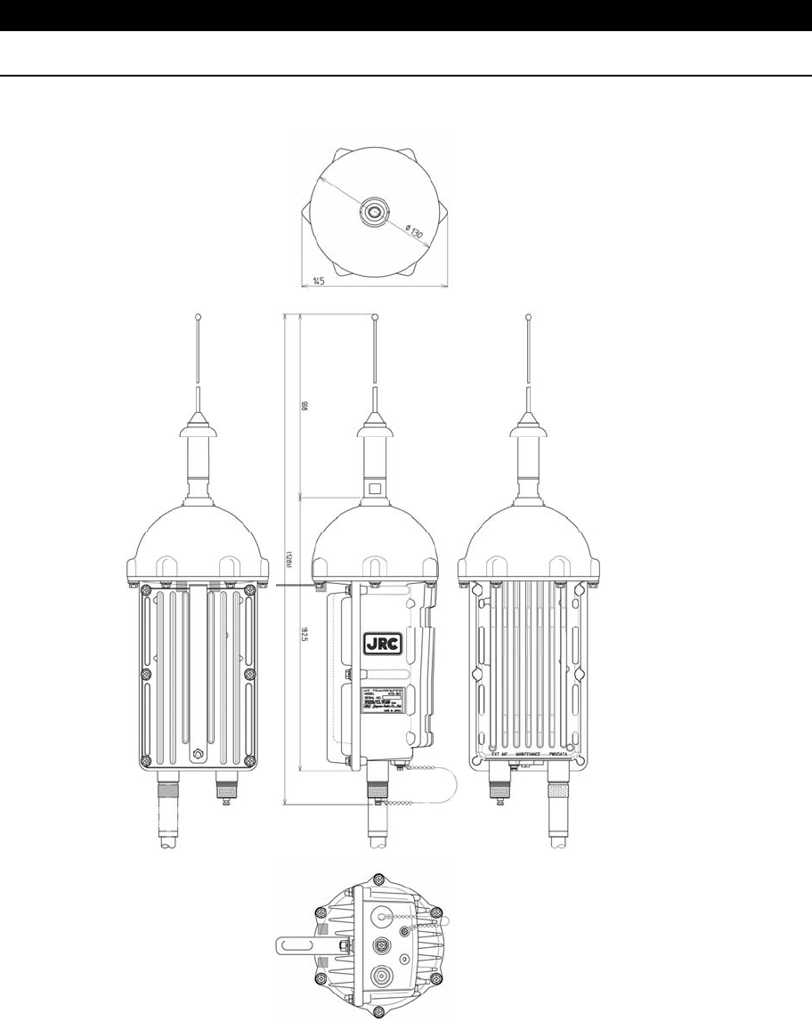
1.4 Outline
x Outline Drawing of NTE-183 AIS Transponder
Unit: mm
Mass: approx. 2.6kg
1-5
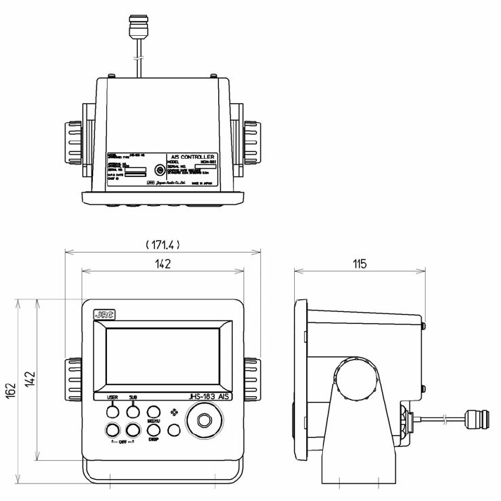
x Outline Drawing of NCM-983 AIS Controller
֤֤֤֤֤֤֤֤֤֤֤֤֤֤֤֤֤֤֤֤֤֤֤֤֤֤֤֤֤֤֤֤֤֤֤֤֤֤֤֤֤֤֤
Unit: mm
Mass: approx. 2.1 kg
1-6
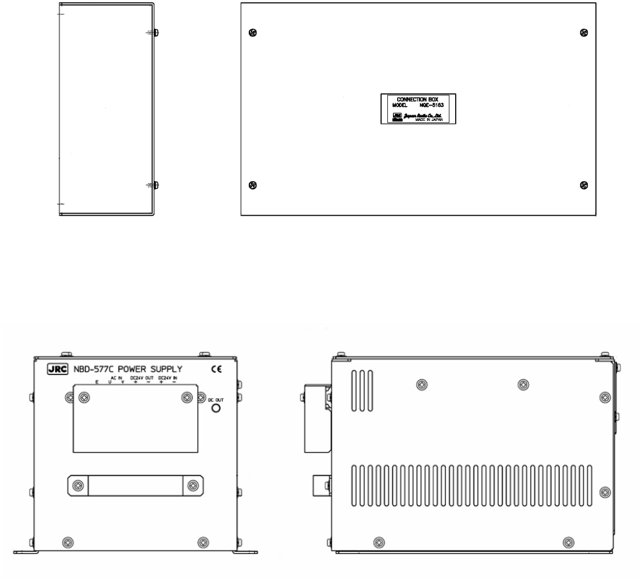
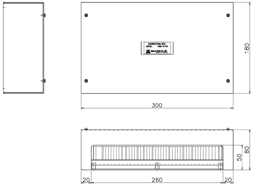
x Outline Drawing of NQE-5183 Connection Box
֤֤֤֤֤֤֤֤֤֤֤֤֤֤֤֤֤֤֤֤֤֤֤֤֤֤֤֤֤֤֤֤֤֤֤֤֤֤֤֤֤֤֤
Unit: mm
Mass: approx. 2.5 kg
.
1-7
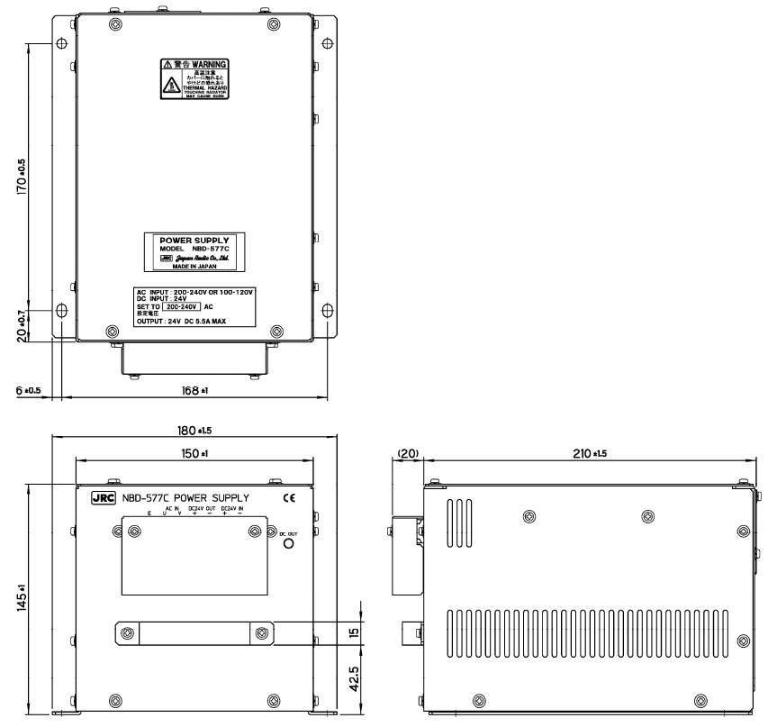
x Outline Drawing of NBD-577C Power Supply Unit
֤֤֤֤֤֤֤֤֤֤֤֤֤֤֤֤֤֤֤֤֤֤֤֤֤֤֤֤֤֤֤֤֤֤֤֤֤֤֤֤֤֤֤
Unit: mm
Mass: approx. 5.2 kg
1-8
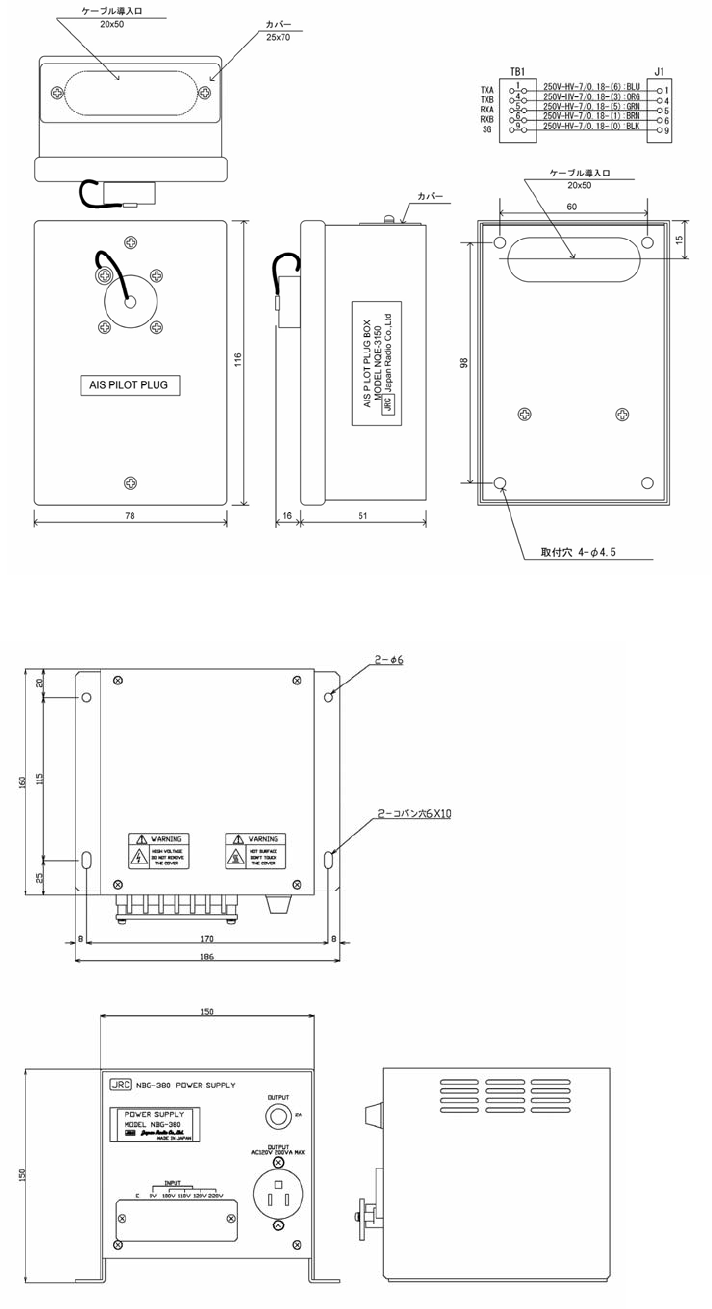
x Outline Drawing of NQE-3150 Pilot Plug Box
֤֤֤֤֤֤֤֤֤֤֤֤֤֤֤֤֤֤֤֤֤֤֤֤֤֤֤֤֤֤֤֤֤֤֤֤֤֤֤֤֤֤֤
x Outline Drawing of NBG-380 Power Supply Unit for Personal Pilot Unit
֤֤֤֤֤֤֤֤֤֤֤֤֤֤֤֤֤֤֤֤֤֤֤֤֤֤֤֤֤֤֤֤֤֤֤֤֤֤֤֤֤֤֤
Unit: mm
Mass: approx 0.36kg
Unit: mm
Mass: approx 6.5kg
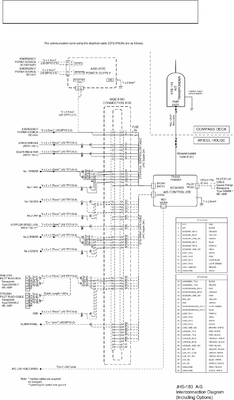
2-1
2. INSTALLATION DIAGRAM
Notes:
Leave installation of this equipment to our service center or agents.
Installation by an unauthorized person may results in malfunction.
2-2
3-1
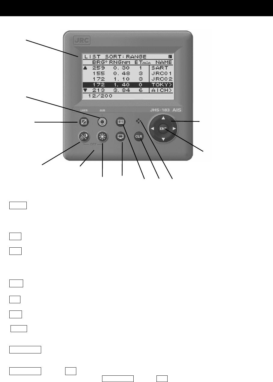
3. PART NAMES AND FUNCTIONS
3.1 NCM-983
AIS Controller
Ԙ
LCD Display
For further information, refer to “4 DISPLAYS on page 4-1”.
ԙ
MENU key
Displays the Main-menu.
Ԛ
Up, Down, Right, Left key
Moves the cursor, scrolls the display screen, and selects the item.
ԛ
ENT key
Determines the selection of an item and fixes a setup.
Ԝ
CLR key
When menu screen is displayed, return to upper menu.
When inputting some items, these inputs are canceled.
When the buzzer sounds, stop the buzzer.
ԝ
DISP key
Change the screen. refer to “4 DISPLAYS”.
Ԟ
DIM key
Adjust the back light brightness of the LCD. the value is up or down by 4 steps by each pressing.
ԟ
SUB key
Display SUB MENU screen.
䢆䎃
USER key
䎃䎃Display the screen that is used frequently. In order to assign the activity to the key, refer to the “5.3.4.2 MY
CONTROLLER”.
ԡ
PWR/CONT key
Turn the power ON. Adjusts the contrast of the LCD, while the power is turned on. The value is up or
down by 13 steps by pressing the key in turn.
Ԣ
PWR/CONT key and DIM key
Turn the power off with pressing both PWR/CONT key and DIM key at the same time.
Ԙ
ԙ
ԟ
Ԡ
ԡ
Ԟ ԝԜ
Buzzer
ԛ
Ԛ
Ԣ
3-2
ԩ
ԧ
Ԩ
ԥ
Ԧ
ԣ
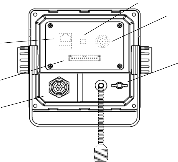
ԣ
POWER/DATA1 connector
Connect to power supply, sensor and external equipment by using controller cable or connect to
connection box (option).
Ԥ
AIS transponder connector
Connect to AIS transponder by a coaxial cable.
ԥ
GND terminal
Connect to Ship ground.
Ԧ
DATA2 connector
Connect to sensor and external equipment by data cable. Or connect to the optional connection box.
ԧ
Pilot Plug
Connect to PC for Pilot by Pilot cable.
Ԩ
LAN connector
Connect to LAN network.
When performing maintenance, connect to PC.
ԩ
Dip switch for terminator
When external sensors are connected in parallel, perform the terminator setting.
=====================
Serial number label (Upper side)
Indicates the own serial number and AIS equipment number.
Ԥ
4-1
.+56 51464#0)'
$4)
c
40)
0/
'6
O
KP 0#/'
5#46
,4%
,4%
61-;
Ť
#+%*
㪞
㪞㪣
㪫㫏㪘㩷㩷㪈㪮 㪘㪣
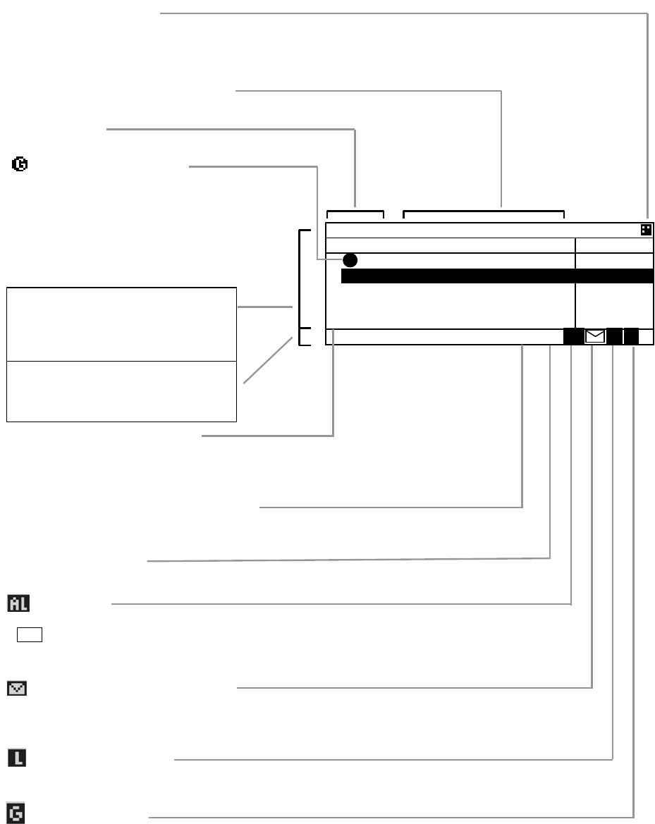
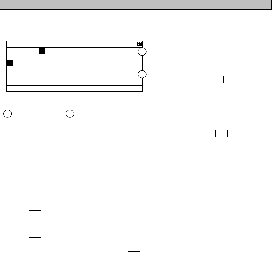
4. DISPLAYS
TxA/TxB/RX Transmission condition
When AIS is transmitting, TxA or TxB is displayed.
When AIS operates in Silent Mode, RX is displayed.
1W Power reduction
When the transmission Power is reduced to 1W, the mark is displayed.
AIS Alarm
When an alarm occurs during operation, this mark flashes, this mark is flashed.
If CLR key is pressed or external equipment outputs the ACK of this alarm,
This mark is changed from flashing to being permanently on.
When the alarm condition returns to normal, the mark is turned off.
Received message indication
When a message is received, this mark is displayed and buzzer sounds.
A
fter opening the message, this mark is turned off.
Long range message
When a long range (LR) message is received, this mark is displayed.
Guard zone Alarm
When the guard zone alarm occurs, this mark is displayed.
㧖GROUP SHIP
When AIS has received the other ships
data that is registered as group ships in the
AIS, then this mark is displayed.
Screen Title
Indicates the screen’s content
The display order of other ships
Indicates the order dis
p
la
y
ed at the LIST SORT screen.
Operation indicator
Indicates the equipment condition.
When these 4 squares are flashing in order, it means normal condition.
ًٕ Arrow indication
If there are ًQTٕOCTM,
It means the screen continues.
Guard mark indication
When other ships enter the guard zone,
this mark is displayed and alarm buzzer sounds.
Main display
Displays “Other ship’s list”, “Other ship’s
detail”, ”Own ship’s detail”, “Menu
display”, ”Graphic display” and so on.
Status bar
Displays “equipment condition”, “the
number of other ships” and so on.
4-2
5-1
5. OPERATION
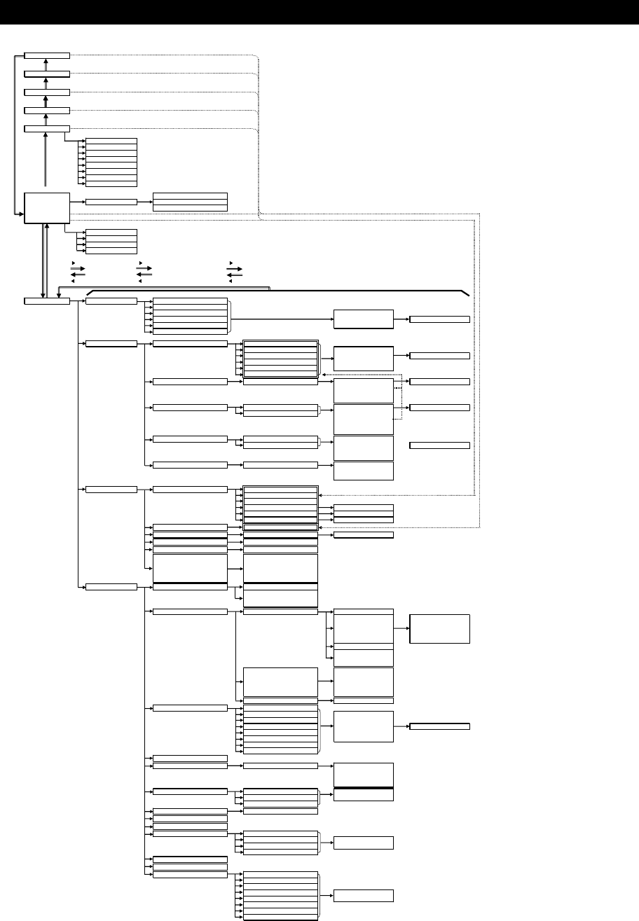
5.1 Menu Tree
POSN/Date
[DISP]
Own ship's TRX condition
[DISP]
Own ship's detail2
[DISP]
Own ship's detail1
[DISP]
Graphic display
[SUB]
1. Range
2. Bearing
3. Sort
4. Name
5 .Guard zone
6. Number of ships
7. Contrast
[DISP] 8. Auto range set
(Power ON)
[ENT] [SUB] Edit and TX
Other ship's detail Info
Interrogation
EXIT [CLR]key + [DISP]key
[DISP] [SUB] [CLR]key + [USER]key
1. Bearing
2. Sort
3. Name
4. Disp
䫹䫹or [ENT] 䫹䫹or [ENT] 䫹䫹or [ENT]
[MENU] 䫹 [CLR]
[DISP]
䫹䫹or [CLR] 䫹䫹or [CLR] 䫹䫹or [CLR]
[MENU]
Main menu 1. Voyage static data 1. Navigational status
2. Destination
3. ETA [SET]
4. Draught [DIST LOAD]
Setting Screen from [DEST LOAD]
5. Cargo/Status [EXIT]
6. Persons on board
2. Message 1. Edit and TX 1. Format/MMSI
2. Category [EDIT]
3. Function [TX] Text edit Screen
(4). Reply [SAVE]
5. Channel [EXIT]
(6). Number of retry
2. TX tray 1. Sent messages [DETAIL VIEW] TX Message Screen
[EDIT]
[DELETE]
[EXIT]
3. RX tray
1. Received safety related messages
[DETAIL VIEW] RX Message Screen
2. Received others messages ([REPLY])
([EDIT])
[DELETE]
[EXIT]
4. Interrogation 1. MMSI [TX]
2. Request [CHECK] Interrogation Screen
[CLEAR]
[EXIT]
5. Long-range Long-range message screen ([REPLY)
([NOT REPLY])
[EXIT]
3. Maintenance 1. Self diagnosis 1. Transponder
2. Controller
3. Controller LAN
4. Transponder log Log screen
5. Controller log Log screen
6. Controller LAN log Log screen
2. Communication test Destination
3. AIS ALARM Alarm information screen Alarm history
4. Sensor status Sensor status screen
5. Event log Log screen
6. Software version
Software version
- Transponder cont
- Controller disp
- Controller LAN
(
- NSK unit
)
4. SET UP 1. Date and time 1. POSN/Time disp
2. Display form
- UTC/LT
- LT diff
2. My Controller 1. LCD adjustment 1. Contrast
2. Dimmer
Dimmer
- Maximum
- Typical
- Minimum
- Alarm
3. Screen saver
4. Back Light
- Operation
- Alarm
2. Sound
Buzzer
- Message
- Guard zone alarm
- Alarm
- Click
3. User key assign User key assign screen
3. Regional channel setting 1. CH A: CH, TRX
2. CH B: CH, TRX [CHECK]
3. TX/RX mode [SAVE]
4. TX power [LIST] Setting List Screen
5. Zone size [CLEAR]
6. Area (NE) [EXIT]
7. Area (SW)
8. Source
4. Power reduction
5. Group ship 1. Ship name,MMSI [SAVE]
[CLEAR]
[ALL CLEAR]
[EXIT]
6. Channel/power setting 1. CH A: CH [SET]
2. CH B: CH [EXIT]
3. POWER
7. Password 1. User level
8. POSN disp setting
9. AIS SART test mode setting
10. Long-range setting 1. LR Broadcast
2. CH A [SET]
3. CH B [EXIT]
4. Long-range response
11.Silent mode
12.CCRP setting
(13. NSK unit) 1. Heading
2. Alarm
3. Type
4. Ratio [SET]
5. Direction [EXIT]
6. Output timing
7. Simulator
8. ERR timing
Other ships list
SUB
SUB
SUB
SUB
SUB
SUB
SUB
SUB
SUB
SUB
5-2
.+56 51464#0)'
$4)
c
40)
0/
'6
O
KP //5+
Ť
㪫㫏㪘
5.2 Basic Operation
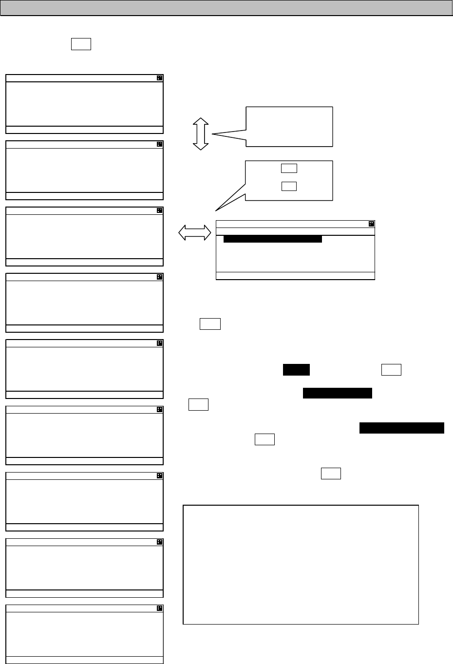
5.2.1 Turning ON the power
Holding down the PWR/CONT key for 1 second turns on the power, the starting screen appears about
2 seconds later, and then the Other Ships List display appears about 10 seconds later.
Caution:
Check the main power supply of the switchboard and a cable connection of NCM-983
AIS controller when the power cannot be turned on.
During operation,
Pressing MENU key displays MAIN MENU.
Pressing DISP key switches the screen.
Pressing OFF key displays the screen for turning off the power.
When alarm buzzer is beeping, press CLR key to stop the beeping. When alarm display is displaying,
press CLR key to close the display. The alarm buzzer can be disabled through the initial setting menu.
(Refer to “5.3.4.2 b) Sound”.)
When the Other Ships List is displayed, transmission is started after 1 minute later.
While the transponder transmits normally, “Tx A (Tx B)” is displayed in the status line. (“TxA” and “TxB”
are indicated alternately. If the transmission interval is 10s, the controller displays “TxA” for 10s and
then “TxB” for 10s and repeats the operation.)
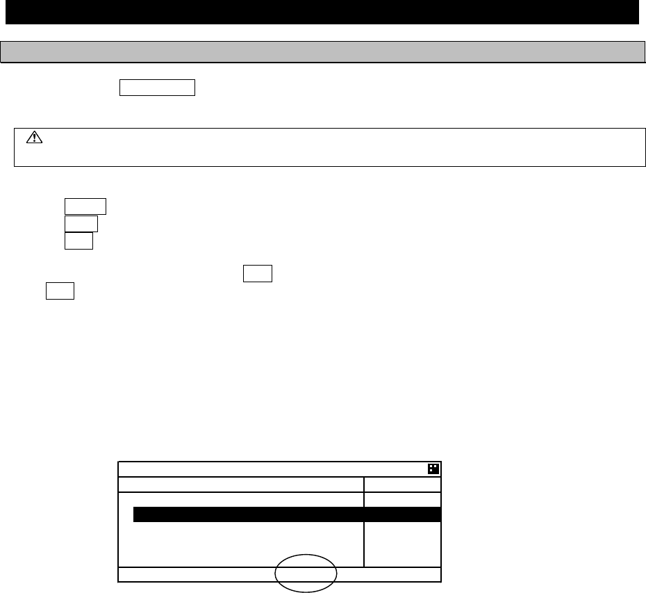
When the saved data is different between AIS Transponder and AIS Controller, the information screen is
displayed.
The following items are displayed in the information screen.
- VOYAGE STATIC DATA : The voyage static data mismatching.
- SHIP STATIC DATA : The ship static data mismatching.
- MMSI / IMO NO. : The MMSI and IMO No. mismatching.
- MMSI SETTING : 000000000 : The MMSI No. is ‘000000000’ setting.
- NG AIS TRANSPONDER [CONTROL UNIT] : Failure of the control unit (CDJ) in
the AIS TRANSPONDER
The cases when there can be a data difference is explained on the following page.
5-3
#.#4/
# /+5/#6%*
=
//5+
+/1
5*+2
85&
?
+0+6+#. 5'66+0) 4'3
4'56#46/#+06'0#0%'
/1&'24'55 #0& *1.&
=
294
%106
?
=
&+/
?
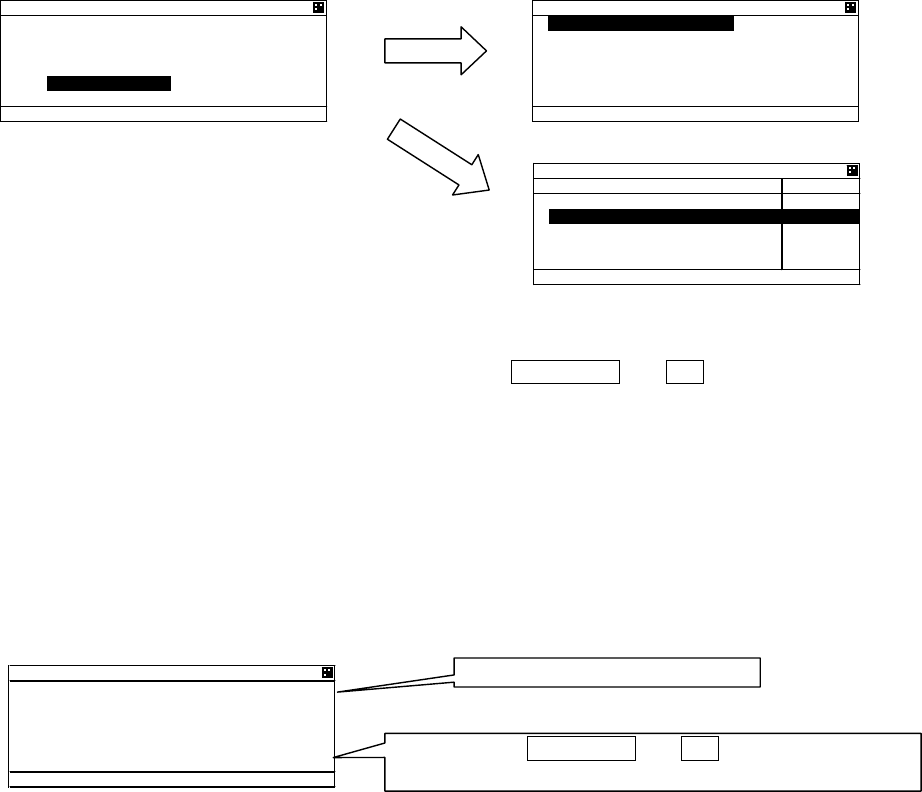
a) The voyage static data mismatch
When only voyage data is different, it is displayed as follows.
When [OK] is selected, voyage static data setting screen is displayed.
When [CANCEL] is selected, LIST SORT screen is displayed.
Confirms the voyage data and select [ENT].
Refer to 5.3.1 VOYAGE DATA SETTING for the change of the setting and the operating method.
b) Other data mismatching
When the following item is displayed, press and hold PWR/CONT and DIM keys together until the
power is turned off (refer to 5.2.2).
- SHIP STATIC DATA
- MMSI / IMO NO.
- MMSI SETTING : 000000000
According to the information screen, contact our service center or agents.
Example) Ship static data, MMSI/IMO No., Voyage static data mismatching
Different contents are displayed.
Press and hold PWR/CONT and DIM keys together in order
to turn off the power.
Select [CANCEL], LIST
SORT screen is
displayed.
Select [OK], VOYAGE DATA
screen is displayed.
85& 4'%10(+)
# /+5/#6%*
=
81;#)' #
?
4'%10(+)74'
!
=
1-
?
=
%#0%'.
?
.+56 51464#0)'
$4)
c
40)
0/
'6
O
KP 0#/'
5#46
,4%
,4%
61-;
Ť
#+%*
81;#)' #
0#856#675
'0)#)'& +0 (+5*+0)
&'56+0#6+10
,#2#0
'6#
Ť
5-4
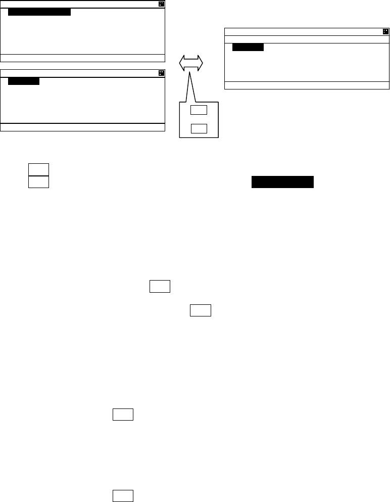
5.2.1.1 Other Ships List
After turning on the power, “LIST SORT” screen for other ships list appears. If “MAIN MENU” screen is
displayed, press CLR key and “LIST SORT” screen is appeared.
In order to select a ship in “LIST SORT” screen, press “”key or ““key.
Press ENT key, the display is switched to “OTHER SHIP’S DETAIL” information screen. (Refer to
5.2.1.2 Other Ship’s Detail Information). Press CLR key at “OTHER SHIP’S DETAIL” information screen,
the display is switched to “LIST SORT” screen again.
When other ship’s MMSI or ship’s name is more than 5 characters, “>” is displayed at the right edge in
“MMSI” display. In this case, press “” key in order to scroll it. To return its display, press “” key.
When the other ships list has more than 5 ships, “” mark is displayed on the bottom line in “LIST
SORT” screen. Press the “” key to move the cursor to the last line in the screen, and press the “”
key one more time to scroll the other ships list downward.
When the other ships list can be scroll upward, “” mark is displayed on the top line. Press the “” key
to move the cursor to the first line in the screen, and press the “” key one more time to scroll the other
ships list upward.
When scroll a lists, press and hold “” key or “” key.
: Ability to scroll
㧖㧦Group ship
㧔See 5.3.4.5㧕
Curso
r
㧦Ability to scroll
Press key to scroll to
the right.
Press key to scroll to
the left
.+56 51464#0)'
$4)
c
40)0/ '6
O
KP 0#/'
Ţ 0+*1
,4%
,4%
61-;
Ť #+%*
.+56 51464#0)'
$4)
c
40)
0/
'6
O
KP //5+
Ť
.+56 51464#0)'
$4)
c
40)
0/
'6
O
KP //5+
Ť
5-5
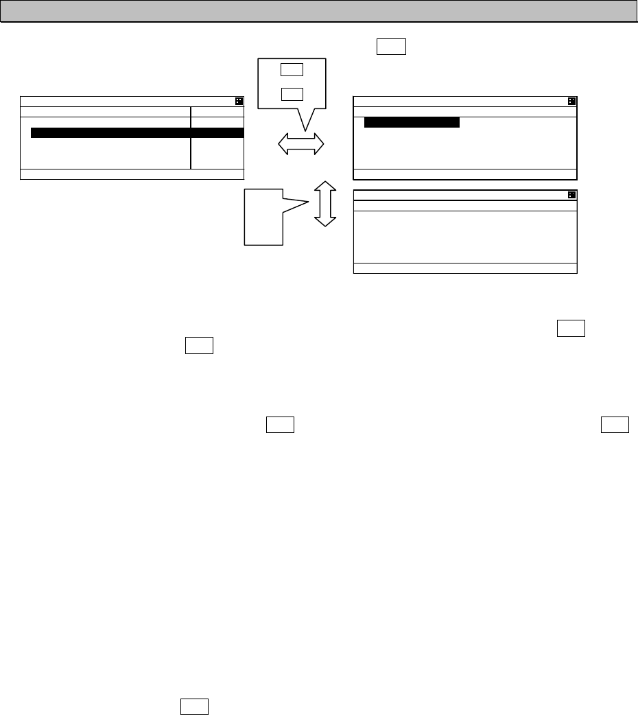
5.2.1.2 Other Ship’s Detail Information
In order to see detail information of a ship selected at “LIST SORT” screen or “GRAPHIC” display
screen, Press ENT key, and then the screen is switched to “OTHER SHIP’S DETAIL” information
screen.
When the display is changed the next page / the previous page,
press “”key or ““key.
Press SUB key in order to display the Sub menu, and then the
cursor can be moved with “”key or ““key.
When the display is switched to “LIST SORT” screen for
other ships list, select [EXIT], and then press ENT key.
When the display is switched to “EDIT AND TX” screen for
sending message, select [EDIT AND TX], and then press
ENT key. (refer to “5.3.2.1 Editing / Sending Messages.”)
When the display is switched to “INTERROGATION” screen
for interrogating to other ship, select [INTERROGATION],
and then press ENT key. (refer to “5.3.2.4 Interrogation.”)
In order to switch to “LIST SORT” screen for other ships list (or
“GRAPHIC” display screen), press CLR key.
ً
or
ٕ
SUB
or
CLR
16*'4 5*+2
5 &'6#+.
57$ /'07
=
'&+6 #0& 6:
?
=
+06'441)#6+10
?
=
':+6
?
The contents of screen 8/9, 9/9 are shown below.
CARGO/SATUS: Cargo type
MF ID: Manufacture code (factory code)
MODEL CODE: Model information
(e.g. AIS JHS-183, MF ID:JRCޔMODEL CODE:3㧕
NO: Serial number of the other’s AIS
CPA: Closest point of approach
TCPA: Time to closest point to approach
BEARING: The direction of the ship
RANGE: The ran
g
e from the shi
p
.
16*'4 5*+2
5 &'6#+.
//5+
0#/'
,4% /#47
+/1 01
%#.. 5+)0
Ť
16*'4 5*+2
5 &'6#+.
Ţ2150 &'8+%'
)25
.#6
c
0
.10
c
'
51) MP
Ť%1)
c
16*'4 5*+2
5 &'6#+.
Ţ*&)
c
416
c
OKP
2150 37#.+6;
2150 /
2#.19 4#+/01 75'
Ť6+/' 56#/2
16*'4 5*+2
5 &'6#+.
Ţ5;0% 56#6'
76% &+4'%6
4%8 56#6+105
Ť
16*'4 5*+2
5 &'6#+.
Ţ0#8 56#675
70&'4 9#; 75+0) '0)
+0'
&'56+0#6+10
,#2#0
Ť
16*'4 5*+2
5 &'6#+.
Ţ'6#
/
&*/
&'%
&4#7)*6
O
.'0)6*
Ť/
16*'4 5*+2
5 &'6#+.
Ţ$'#/
/
6;2' 1( 5*+2
%#4)1 5*+25
Ť
16*'4 5*+2
5 &'6#+.
Ţ%#4)1
56#675
#.. 5*+25 1( 6*+5 6
;2'
%.#55%.#55 #
/( +&
Ť/1&'. %1&'
16*'4 5*+2
5 &'6#+.
Ţ01
%2# 0/
6%2# OKP
$'#4+0)
c
4#0)' 0/
5-6
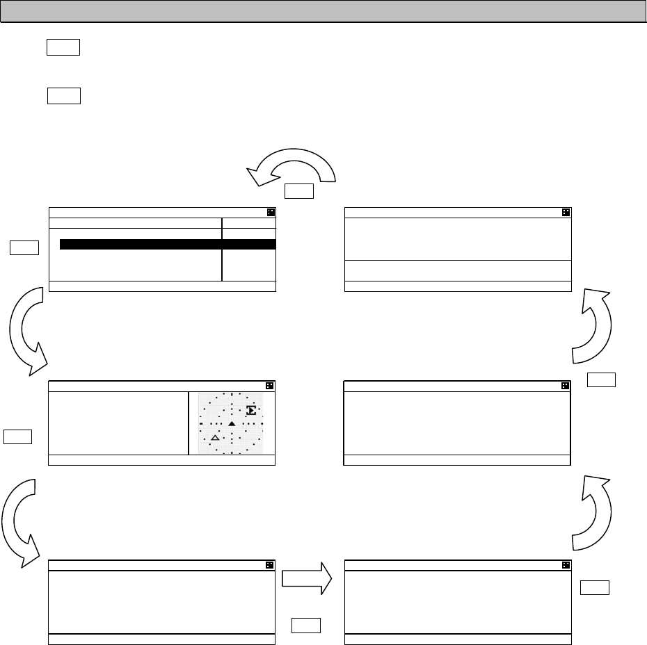
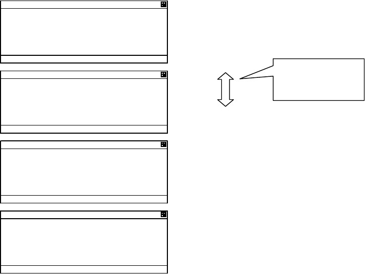
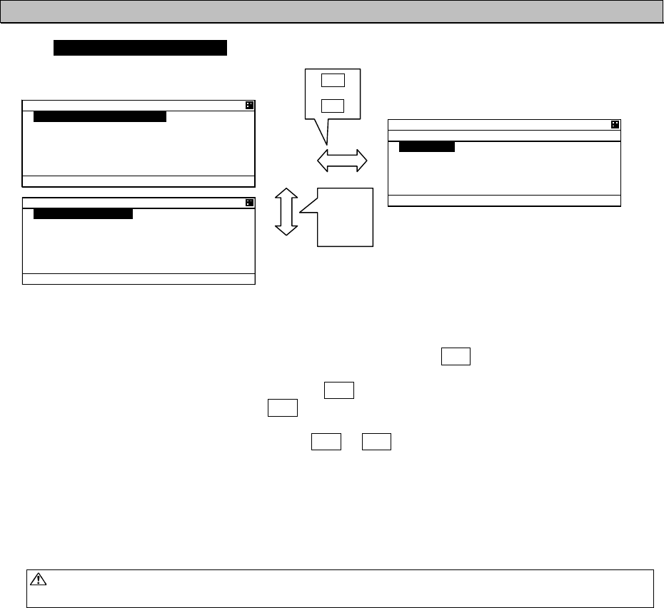
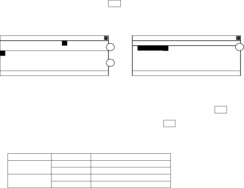
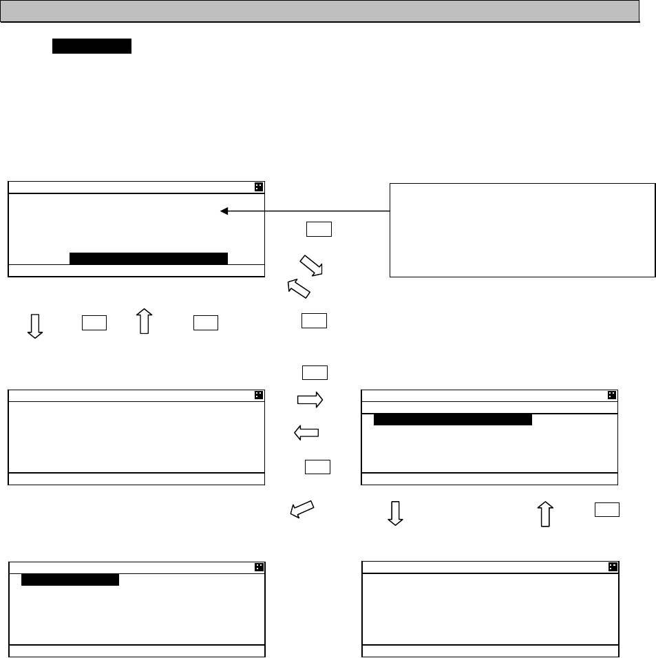
5.2.1.3 Own Ship’s Detail Information
Press DISP key at “GRAPHIC” display screen and then “OWN SHIP’S DETAIL” screen is displayed.
Own ship’s information consist of 2 kinds of own ship’s detail information screens and own ship’s TRX
information screen.
When DISP key is pressed, each screen is switched according to the following flow:
٨“LIST SORT” Screen
for Other Ships List
٨“POSN/DATE” Screen
for Position / Date, Time
٨“GRAPHIC” Display Screen ٨“OWN SHIP’S TRX”
Information Screen
٨“OWN SHIP’S DETAIL 1”
Information Screen
٨“OWN SHIP’S DETAIL 2”
Information Screen
.+56 51464#0)'
$4)
c
40)
0/
'6
O
KP 0#/'
5#46
,4%
,4%
61-;
Ť
#+%*
190 5*+2
564:
%* #
%* $
6: 219'4 *+)*
/1&'
#$
%* # 6:
4:
Ť
%* $ 6:
4:
190 5*+2
5 &'6#+.
//5+
0#/'
,4% /#47
+/1 01
%#.. 5+)0
Ť
DISP
DISP
DISP
DISP
DISP
DISP
21506+/'
6+/' 76%
'
/#;
0
c
'
c
190 5*+2
5 &'6#+.
2150 &'8+%'
)25
.#6
c
0
.10
c
'
51) MP
Ť
%1)
c
)4#2*+% 40) 0 72
,4%
$4)
c
40) 0/
*&)
c
51) MP
%1)
c
5-7
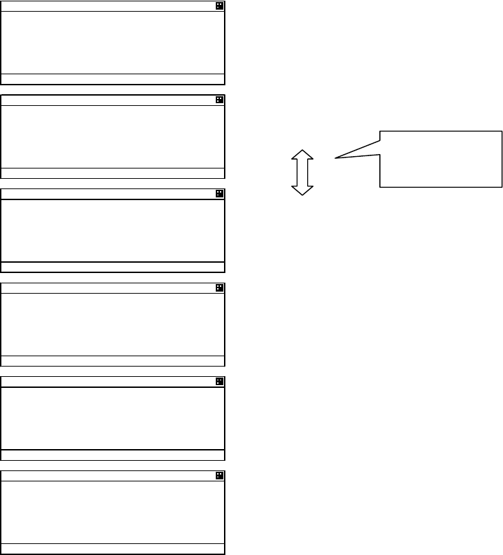
Contents for “OWN SHIP’S DETAIL 1” information screen are shown below.
Static information of own ship is mainly displayed.
To see the next page/the previous page,
press “”key or ““key.
ً
or
ٕ
190 5*+2
5 &'6#+.
//5+
0#/'
,4% /#47
+/1 01
%#.. 5+)0
Ť
190 5*+2
5 &'6#+.
Ţ#06 2150 ':6 +06
$19 O O
564 O O
214 O O
56# O O
Ť
190 5*+2
5 &'6#+.
Ţ2150 &'8+%'
)25
0#8 56#675
'0)#)'& +0 (+5*+0)
Ť
190 5*+2
5 &'6#+.
Ţ&'56+0#6+10
,#2#0
'6#
/
&*/
&'%
Ť
190 5*+2
5 &'6#+.
Ţ&4#7)*6
O
2'45105 14 /14'
6;2' 1( 5*+2
2#55'0)'4 5*+25
Ť
190 5*+2
5 &'6#+.
Ţ%#4)1
56#675
#.. 5*+25 1( 6*+5 6
;2'
5-8
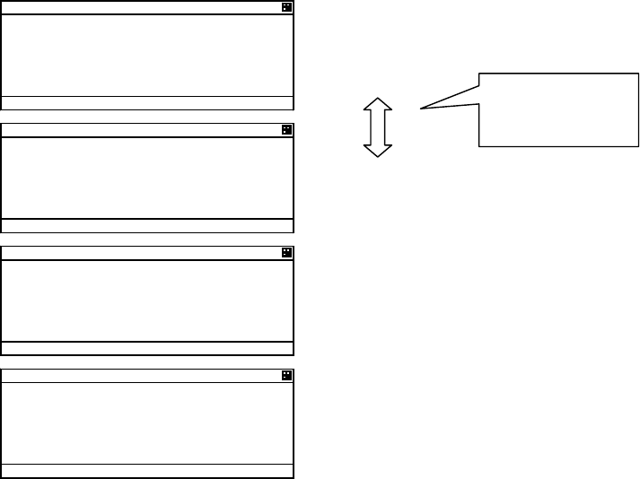
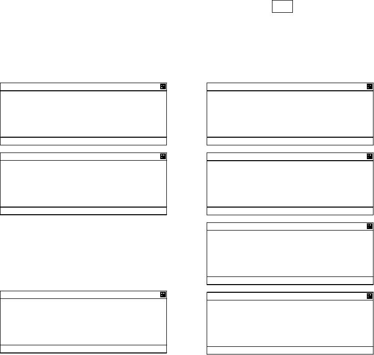
Contents for “OWN SHIP’S DETAIL 2” information screen are shown below.
Dynamic information of own ship is mainly displayed.
To see the next page/the previous page,
press “”key or ““key.
ً
or
ٕ
190 5*+2
5 &'6#+.
2150 &'8+%'
)25
.#6
c
0
.10
c
'
51) MP
Ť
%1)
c
190 5*+2
5 &'6#+.
Ţ
*&)
c
416
c
OKP
2150 37#.+6;
2150 /
2#.19 4#+/01 75'
Ť
6+/' 56#/2
190 5*+2
5 &'6#+.
Ţ
#%% (41/ 4#+/
01 4#+/ 241%'55 #8#
+.#$.'
Ť
190 5*+2
5 &'6#+.
Ţ
5;0% 56#6'
76% &+4'%6
4%8 56#6+105
Ť
5-9
Contents for “OWN SHIP’S TRX” information screen are shown below.
Own ship radio information is mainly displayed.
To see the next page/the previous page,
press “”key or ““key.
ً
or
ٕ
190 5*+2
564:
%* #
%*$
6: 219'4 *+)*
/1&'
#$
%* # 6:
4:
Ť
%* $ 6:
4:
190 5*+2
564:
Ţ
#4'#
0'
0
c
'
c
#4'#
59
0
c
Ť
'
c
190 5*+2
564:
Ţ
5174%'
/#07#. +0276
$#5' 560 //5+
76%
Ť
/#;
190 5*+2
564:
Ţ
<10' 5+<' 0/
5-10
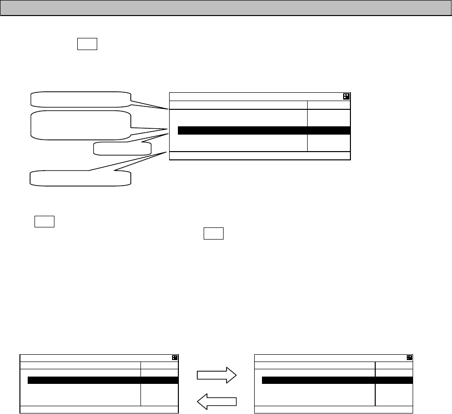
5.2.1.4 Display Setup of Other Ships List
In order to change the display setting of other ship list, press SUB key at “LIST SORT” screen for other
ships list and switch to SUB screen.
When the screen is switched from the SUB menu screen to “LIST SORT” screen, press CLR key or
select [EXIT], and then press ENT key.
At SUB menu screen, Other ship’s bearing basis, sorting of range, TCPA or own group priority order,
and ship’ s name indication in “LIST SORT” screen (upper left figure) can be set.
Select item at the SUB screen and press ENT key, then select a desirable indication and press ENT
key again.
1. BEARING: HEAD UP : Other ship’s bearing value is displayed on the basis of own ship’s bearing.
NORTH UP : Other ship’s bearing value is displayed with the north base.
2. SORT : RANGE : Other ships are displayed in the order of small range from own ship.
TCPA : Other ships are displayed in the order of small TCPA with own ship.
GROUP : Other ships are displayed with the priority for own group ships.
3. NAME : SHIP NAME : When receiving static information, the ship’s NAME is displayed.
MMSI : Ship’s MMSI is displayed.
4. DISP : NORMAL : “LIST SORT” screen is displayed with BRG, RNG, ET and NAME.
TYPE 1 : “LIST SORT” screen is displayed with BRG, RNG, and NAME.
TYPE 2 : “LIST SORT” screen is displayed with BRG, and NAME.
“ETmin” means the “elapsed time” from the last data received, After 7 minutes elapsed, the ship is
erased from the other ship’s list.
Select [SET] and then press ENT key to determine. “LIST SORT” screen for other ships list is displayed
with the setting.
SUB
or
CLR
.+56 51464#0)'
$4)
c
40)
0/
'6
O
KP 0#/'
5#46
,4%
,4%
61-;
Ť
#+%*
.+56 &+525'6
57$ /'07
$'#4+0)0146*72
51464#0)'
0#/'5*+20#/'
&+52014/#.
Ť
=
5'6
?
.+56 &+525'6
57$ /'07
Ţ
=
':+6
?
ً
or
ٕ
5-11
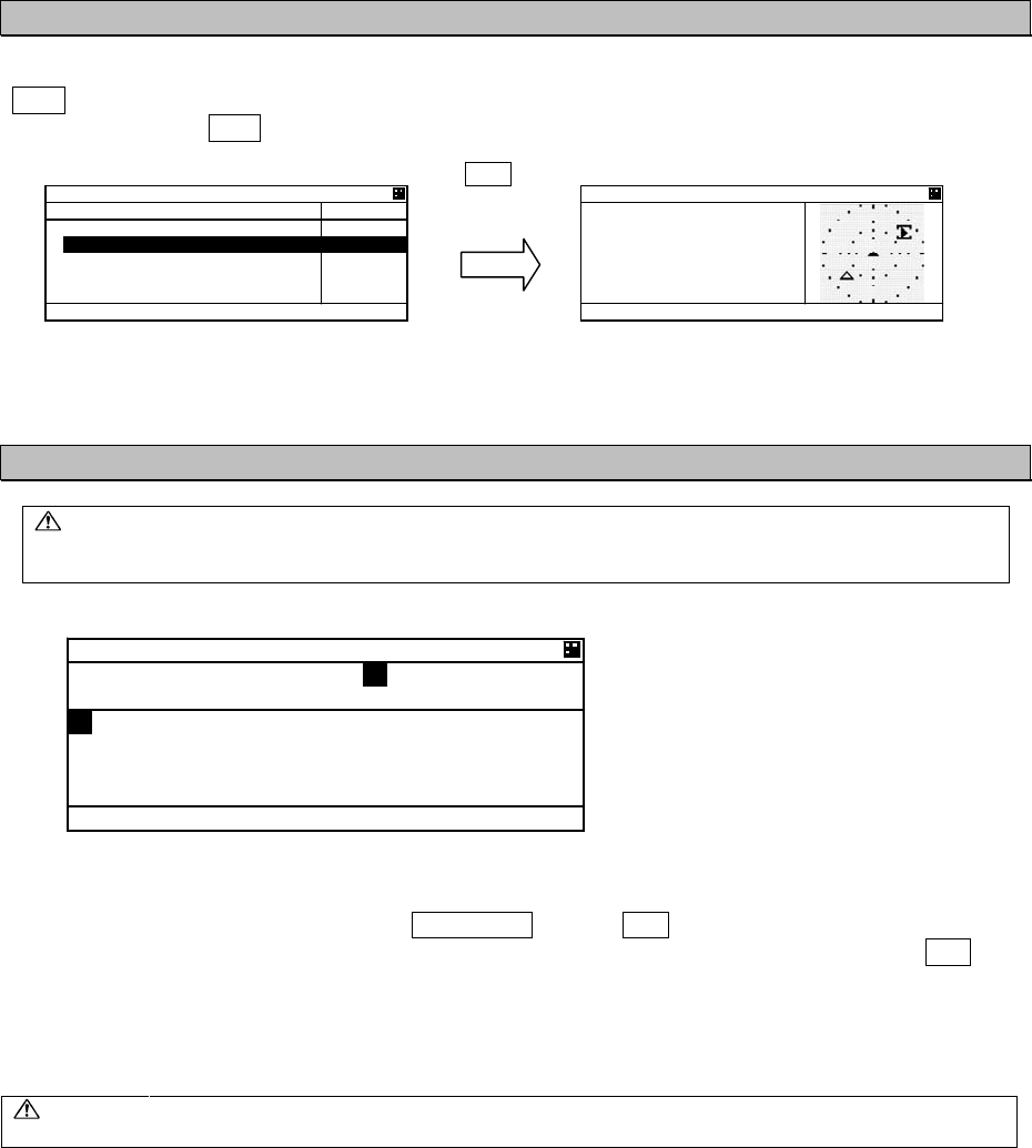
5.2.1.5 Graphic Display
In order to switch from “LIST SORT” screen for other ships list to “GRAPHIC” display screen, press
DISP key.
(Refer to 5.2.1.3 for DISP key operation)
(Refer to 5.4 Graphic Display Function)
5.2.2 Turning OFF the Power
CAUTION:
The PASSWORD must be entered to turn off the power.
The password preset at shipment is “0000”. The administrator must manage
PASSWORD.
When turn off the power, press and hold PWR/CONT key and OFF key together for 1 second and then
“PASSWORD” input screen is displayed. Enter 4 digits of password, select [ENT] and press ENT key.
Password is composed of alphanumeric “A㨪Z” and “0㨪9”.
(Refer to “5.2.4 Character Pad Window Display and Input Method” to input the password.)
After the correct password is inputted, the power is turned off.
Caution:If the power is turned off by main power supply, the setup contents or received
messages may not be saved.
.+56 51464#0)'
$4)
c
40)
0/
'6
O
KP 0#/'
5#46
,4%
,4%
61-;
Ť
#+%*
219'4 1((
2#55914&
#$%&'()*+,-./01234567
89:;<
=
᳖
?
A
!
"
@
=
'06
?
=
':+6
?
DISP
)4#2*+% 40) 0 72
,4%
$4)
c
40) 0/
*&)
c
51) MP
%1)
c
5-12
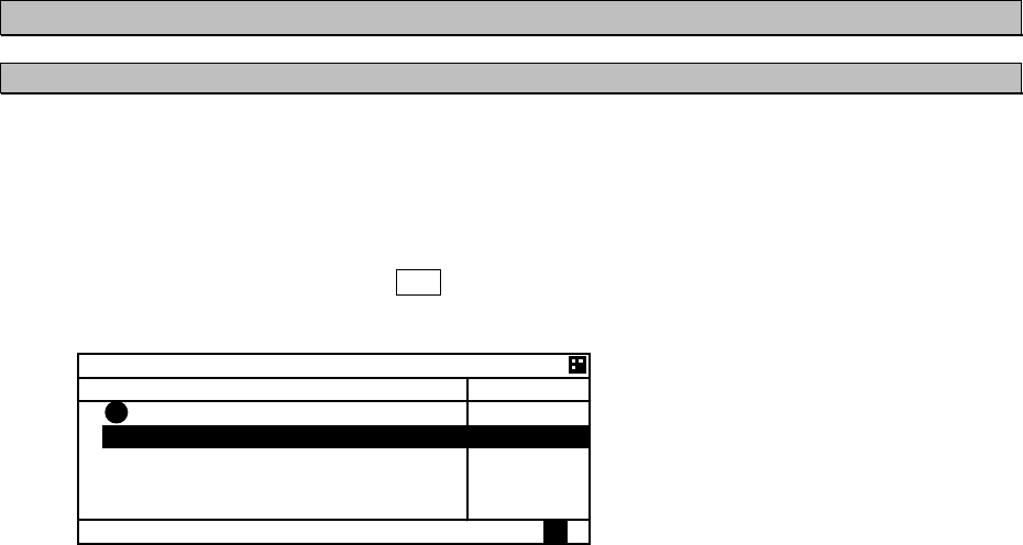
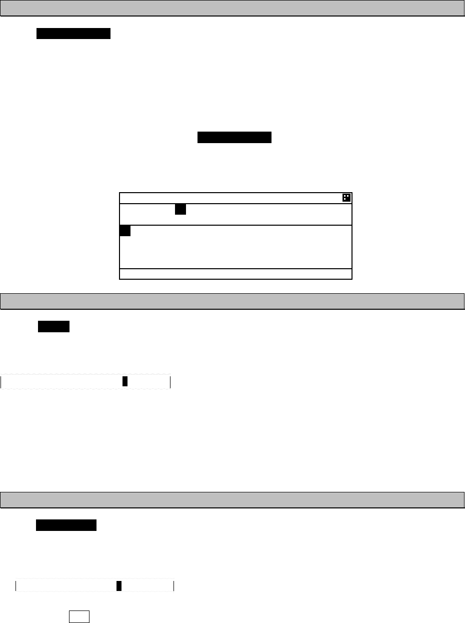
5.2.3 Alarm
5.2.3.1 Guard Zone Alarm
If a ship enters within the guard zone range, the alarm status “G” appears on the bottom of the screen
and an alarm buzzer sounds. In order to set GUARD ZONE, refer to “5.4.3.2 Display Item Explanation”.
The setting default is “OFF”. In case GUARD ZONE alarm is set “ON” and the alarm sound is set “OFF”
in the BUZZER setting, the GUARD ZONE alarm does not sound.
The ship within the guard zone range is displayed “G” in the left side of the line.
In order to stop the alarm buzzer, press CLR key.
.+56 51464#0)'
$4)
c
40)
0/
'6
O
KP 0#/'
5#46
,4%
,4%
61-;
Ť
#+%*
㪞
㪞
5-13
5.2.4 Character Pad Window Display and Input Method
a) Inputting characters
When character input is needed, the character pad window is displayed.
When character input operation starts,
the cursor is on “A” in the character pad
window.
Pressing ““ in the arrow key, the cursor is
moved to like that “B”, “C”, “D”, ----.
Set the cursor on a desirable input
character, and then press ENT key.
The number of characters is displayed in the bottom.
Text Setting Window Character Pad Window
- In order to move the cursor to the other window (Ԙwindow ÅÆԙwindow), press SUB key.
- When clear all inputting characters, select [AC] and then the cursor is moved to the top in the
character input line.
- When clear the current inputting character, select [C] and then the cursor is moved to the
one-character front.
b) Inserting a character
The procedure which inserts a character in the text is followings:
1. Press SUB key in order to move the cursor in Text window.
2. Then the cursor in Text Window can be moved with the arrow key.
Therefore move the cursor to insert position in the text.
3. Press SUB key in order to move the cursor in Character pad window.
Select a desirable insert character and press ENT key.
Therefore the selected character is inserted at the cursor position in Text window.
4. After inserted characters, if you wish to move the cursor to the end of the text, press SUB key to
move the cursor in Text window, and then move the cursor to the end of the text.
5. Additional characters can be inputted at the end of the text.
1 2
&'56+0#6+10
61-;1
#$%&'()*+,-./01234567
89:;<
=
᳖
?
A
!
"
@
=
%
?
=
#%
?
=
1-
?
=
':+6
?
1
2
5-14
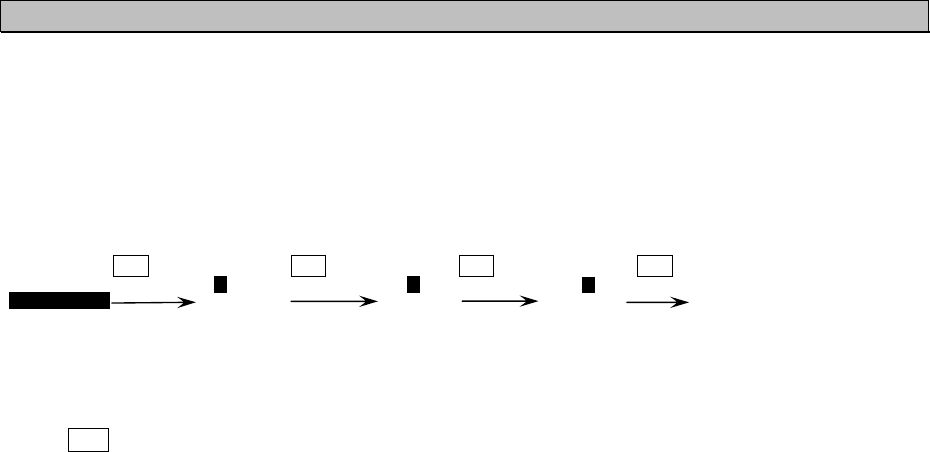
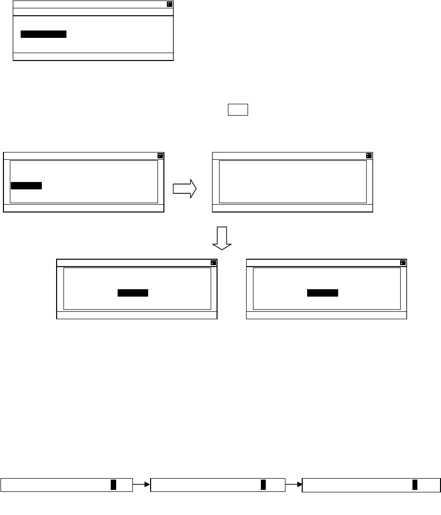
5.2.5 Numerical Input
The procedure for numerical input is as follows:
The following is inputting a draught value to explain the procedure.
When CLR or left key is pressed, the cursor is moved back to 1 digit left position.
4. DRAUGHT:
(
Cursor
)
e.g.) DRAUGHT: 12.3 m
(The draught has been set.)
(Select ‘1’) (Select ‘2’) (Select ‘3’䋩
1 0.0 m 1 2 .0 m 12. 3 m
ENT or
Right key
ENT or
Right key
ENT or
Right key
ENT
Up
down
key
Up
down
key
Up
down
key

5-15
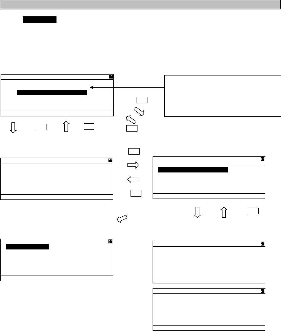
5.3 Main Menu
“MAIN MENU” screen displays menu items for setting, sending messages, and maintenance, etc.
In order to display “MAIN MENU” screen, press MENU key during displaying any screen.
(At “Power off screen” and “ALARM popup screen”, MENU key is invalid.)
Press key or key for moving the cursor
over the menu to select a desirable item.
Press ENT key, and then the selected menu is
displayed.
The outline of the each menu is as follows:
1. VOYAGE STATIC DATA SETTING㨯㨯㨯displays a menu for setting voyage information (Refer to 5.3.1)
2. MESSAGE㨯㨯㨯displays a menu for sending/receiving messages (Refer to 5.3.2).
3. MAINTENANCE㨯㨯㨯displays a menu for setting maintenance conditions (See 5.3.3).
4. SET UP㨯㨯㨯displays a menu for setting the device (See 5.3.4).
/#+0/'07
81;#)' #
/'55#)'
/#+06'0#0%'
5'6 72
=
':+6
?
5-16
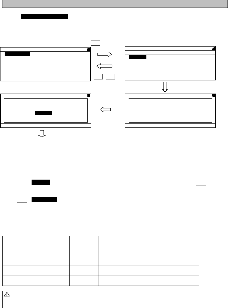
5.3.1 Voyage data setting
Select 1. VOYAGE STATIC DATA in “5.3 MAIN MENU” screen, “VOYAGE DATA” menu screen for
setting is displayed.
Press key or key to select a desirable setting item and press ENT key, then selecting item and
inputting data are available.
To switch to “VOYAGE DATA” menu screen, press CLR key during selecting item or inputting data.
To switch to “MAIN MENU” screen, press CLR key at “VOYAGE DATA” menu screen.
When the SUB menu screen is displayed, press SUB or CLR key and switch to “VOYAGE DATA” menu
screen.
Select [SET] at the sub menu screen, the setting is saved. If [EXIT] is selected at the sub menu screen,
the screen is returned to “MAIN MENU”.
In order to select a destination from past inputted destinations, Select [DEST LOAD] at the sub menu.
(Refer to “5.3.1.7 Re-load destination”.)
The outline of the each menu is as follows:
1. NAV. STATUS㨯㨯㨯select navigational status. (Refer to 5.3.1.1)
2. DESTINATION㨯㨯㨯input the destination. (Refer to 5.3.1.2)
3. ETA㨯㨯㨯input ETA(expected time for arrival). (Refer to 5.3.1.3)
4. DRAUGHT㨯㨯㨯input draught value.( Refer to 5.3.1.4)
5. CARGO/STATUS㨯㨯㨯select cargo/status.( Refer to 5.3.1.5)
6. PERSONS ON-BOARD㨯㨯㨯input the number of persons on-board.( Refer to 5.3.1.6)
Caution: In order to save the setting, select [SET] at the SUB menu.
If you switch to any other screen without selecting [SET], the setting is not saved.
ً
or
ٕ
SUB
or
CLR
81;#)' #
0#856#675
'0)#)'& +0 (+5*+0)
&'56+0#6+10
,#2#0
'6#
Ť
81;#)' #
Ţ
&4#7)*6
/
%#4)1
56#675
#.. 5*+25 1( 6*+
2'45105 10 $1#4&
81;#)' #
57$ /'07
=
5'6
?
=
&'56 .1#&
?
=
':+6
?

5-17
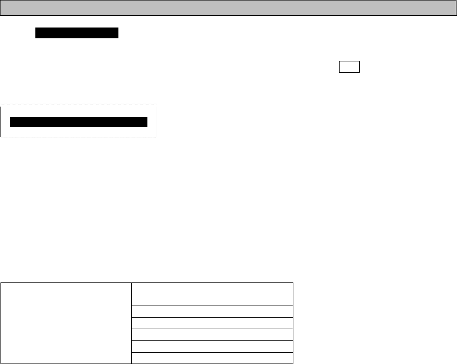
5.3.1.1 Navigational Status
Select 1. NAV. STATUS at “VOYAGE DATA” menu screen (refer to “5.3.1 VOYAGE DATA SETTING”),
the navigational status can be selected. Press key or key in order to select a desirable item, and
then press ENT key.
VOYAGE DATA
1.NAV. STATUS :
RESTRICTED MANOEUV>
The Navigational Status can be selected from listed below:
UNDER WAY USING ENGINE
AT ANCHOR
NOT UNDER COMMAND
RESTRICTED MANOEUVRABILITY
CONSTRAINED BY HER DRAUGHT
MOORED
AGROUND
ENGAGED IN FISHING
UNDER WAY SAILING
RESERVED FOR HSC (High Speed Craft)
RESERVED FOR WIG (Wing-in-Ground Effect Craft)
NOT DEFINED
5-18
5.3.1.2 Destination Input
Select 2.DESTINATION at “VOYAGE DATA” menu screen (refer to “5.3.1 VOYAGE DATA SETTING”),
the name of the destination can be inputted. The name can be inputted with using the Character Pad
window at the bottom of the screen.
Refer to “5.2.4 Character Pad Window Display And Input Method” in order to input characters.
Operation at the Destination Name Input screen is as follows:
Up to 20 characters can be entered for naming destination.
Select [EXIT] on the bottom right of the Character Pad window, discard a current inputting
characters and the cursor is returned to 2.DESTINATION.
Select [OK], Name of destination has been set. and the cursor moves to the next item “3.ETA”.
Select [AC], all characters inputted are cleared, and the cursor moves to the top of the line.
Select [C], the current character is cleared, and the cursor moves to the one- character front.
5.3.1.3 Estimated Time of Arrival (ETA) Input
Select 3. ETA at “VOYAGE DATA” menu screen (refer to “5.3.1 VOYAGE DATA SETTING”), ETA
(Expected Time of Arrival) can be inputted.
(Refer to “5.2.5 Numerical Input” for numerical input procedure.)
ETA input procedure is as follows:
Input numerals for ETA on UTC in the order of Month-Day-Hour-Minute with key or key.
‘/’ will be inserted automatically.
After inputting the last “Minute”, the cursor moves to the next item “4. DRAUGHT” (Draught Value
Input).
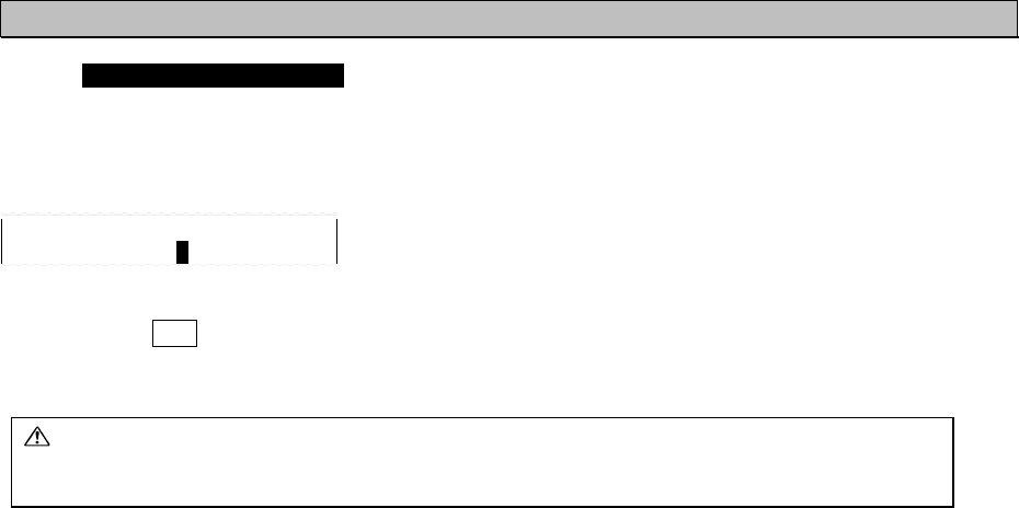
5.3.1.4 Draught Value Input
Select 4. DRAUGHT at “VOYAGE DATA” menu screen (refer to “5.3.1 VOYAGE DATA SETTING”), the
draught value can be inputted. Input a value according to the procedure of ”5.2.5 Numerical Input”.
The input range of draught is between 0 and 99.9 m.
When the inputted value is greater than 25.5 m, “25.5M OR GREATER” is displayed.
After pressing ENT key and the draught value has been set. Then the cursor moves to the next item
“5.CARGO/STATUS”.
3.ETA : 12/31 23:31
4.DRAUGHT : 25.4M
&'56+0#6+10
61-;1
#$%&'()*+,-./01234567
89:;<
=
᳖
?
A
!
"
@
=
%
?
=
#%
?
=
1-
?
=
':+6
?
5-19
5.3.1.5 Cargo Type Selection
Select 5.CARGO/STATUS at “VOYAGE DATA” menu screen (refer to “5.3.1 VOYAGE DATA SETTING”),
Cargo Type can be selected.
Press key or key in order to select a desirable item, and then press ENT key. And the cursor
moves to the next item “6. PERSONS ON BOARD”.
The cargo type selection is changed by the setting of Ship type as follows:
Depending on the type of the ship, this “CARGO TYPE” cannot be selected. In such a case, NOT
AVAILABLE is displayed.
5.CARGO/STATUS:
NO ADDITIONAL INFORMATION
SHIP TYPE CARGO TYPE
CATEGORY A(DG/HS/MP)
CATEGORY B(DG/HS/MP)
CATEGORY C(DG/HS/MP)
CATEGORY D(DG/HS/MP)
NO ADDITIONAL INFORMATION
WIG
HIGH SPEED CRAFT
PASSENGER SHIPS
CARGO SHIPS
TANKER
OTHER TYPE OF SHIP ALL SHIPS OF THIS TYPE
5-20
5.3.1.6 Persons on Board Input
Select 6. PERSONS ON BOARD at “VOYAGE DATA” menu screen (refer to “5.3.1 VOYAGE DATA
SETTING”), the number of persons on board can be inputted.
Input a value with key or key according to the procedure of ”5.2.5 Numerical Input”. The input
range of PERSONS is between 0 and 9999.
When the inputted number is more than “8191”, “8191 OR MORE” is displayed.
6. PERSONS ON BOARD :
8191
After pressing ENT key at the last digit, the inputted PERSONS has been set. And the cursor returns to
“6. PERSONS ON BOARD”.
Caution: In order to save the setting, select [SET] in the SUB menu screen.
If [SET] in the SUB menu is not selected, the setting is not saved.
5-21
5.3.1.7 Re-load Destination from history Data
Select [DEST LOAD] in the sub menu in “5.3.1 VOYAGE DATA SETTING”, Destinations list (current
destination and 4 destinations in the past) is displayed.
Select the destination from the list and press ENT key, then the screen is switched to “VOYAGE DATA”
menu screen and the selected one is displayed at the 2.DESTINATION.
If CLR key is pressed at “DEST LOAD” screen, the re-load operation is canceled and switch back to
“VOYAGE DATA” screen.
If a past destination is selected from the DEST LOAD screen, the destination is displayed as the newest
at the DEST LOAD screen.
e.g.) If TOKYO is selected on the setting procedure above, the “DEST. LOAD” screen is changed as
shown below.
㧔Example㧕
YOKOHAMA TOKYO
ABCDEFGHIJKLMNOPQRST YOKOHAMA
TOKYO ABCDEFGHIJKLMNOPQRST
AFRICA AFRICA
01234567890123456789 01234567890123456789
Select
[DEST LOAD]
CLR key
Select a destination, and then
press ENT key.
81;#)' #
57$ /'07
=
5'6
?
=
&'56 .1#&
?
=
':+6
?
&'56 .1#&
;1-1*#/#
#$%&'()*+,-./012345
6
61-;1
#(4+%#
81;#)' #
0#856#675
'0)#)'& +0 (+5*+0
&'56+0#6+10
61-;1
'6#
Ť
Ť

5-22
5.3.2 Message Menu
Select 2. MESSAGE in “MAIN MENU” screen, “MESSAGE” menu screen is displayed.
When move the cursor for selecting a desirable
item in menu, press key or key.
then press ENT key to display a screen of the
selected item.
Press CLR key at the “MESSAGE” menu
screen, then switch back to “MAIN MENU”
screen.
The outlines of each menu items are as follows:
1. EDIT AND TX 㨯㨯㨯Displays a menu for message editing and transmission. (Refer to 5.3.2.1)
2. TX TRAY 㨯㨯㨯Displays a menu for TX (transmission) message tray. (Refer to 5.3.2.2)
3. RX TRAY 㨯㨯㨯Displays a menu for RX (reception) message tray. (Refer to 5.3.2.3)
4. INTERROGATION 㨯㨯㨯Displays a menu for interrogation. (Refer to 5.3.2.4)
5. LONG-RANGE 㨯㨯㨯Displays a menu for long-rang messages.
This menu only works, when a long-range communication device is connected.
(Refer to 5.3.2.5)
/'55#)'
'&+6 #0& 6:
6: 64#;
4: 64#;
+06'441)#6+10
.10)4#0)'
5-23
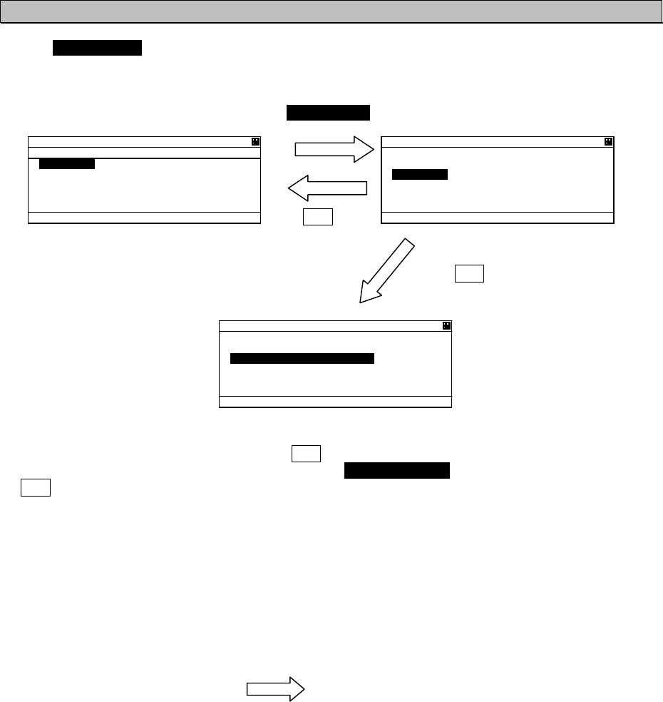
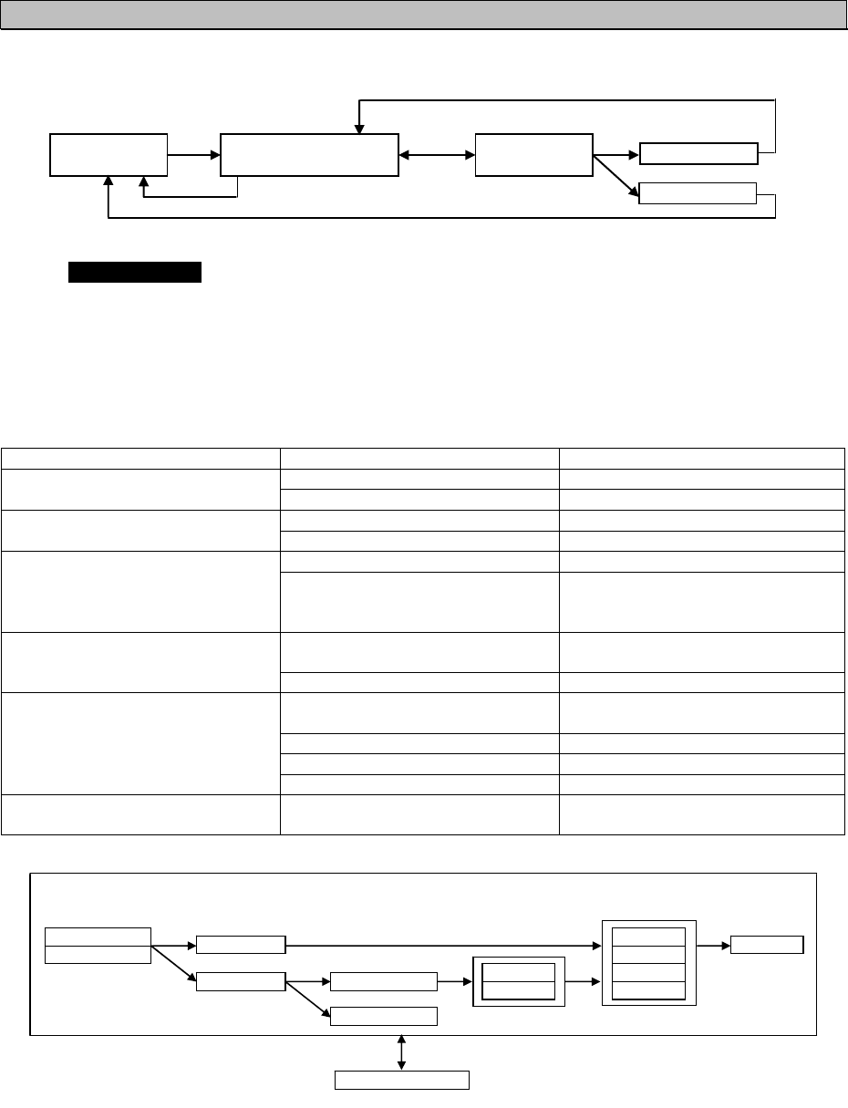
5.3.2.1 Editing / Sending Messages
Editing messages and transmitting is according to the below flow.
㫄㪼㫊㫊㪸㪾㪼㩷㫄㪼㫅㫌
㫊㪺㫉㪼㪼㫅 㪈㪅㪜㪛㪠㪫㩷㪘㪥㪛㩷㪫㪯 㪲㪜㪛㪠㪫㪴 㪲㪫㪯㪴
㪚㪣㪩㩷㫂㪼㫐
㪪㪬㪙㩷㫂㪼㫐
㪲㪪㪘㪭㪜㪴
Select 1.EDIT AND TX at “5.3.2 MESSAGE MENU” and then “MESSAGE TYPE” setting screen is
displayed.
a) MESSAGE TYPE
For defining a message type of each message, select a status at the each message type.
The procedure is as follows.
Message Type
Message Type Status Remarks
BROADCAST Send to all ships
FORMAT ADDRESSED Send to individual ship
SAFETY Message relating to safety
CATEGORY ROUTINE Messages relating to daily tasks
TEXT Sending text message
FUNCTION
(Function Identifier)
CAPABILITY INTERROGATE
(In case, FORMAT: ADDRESSED,
CATEGORY:ROUTINE )
Sending interrogation for items
which can be answered
ON Reply request for sent messages
for sent messages
REPLY
(In case, FORMAT: ADDRESSED) OFF No reply request
AUTO Select channel automatically and
send messages
A Send on Ach
B Send on Bch
CH
A/B Send on both A&B ch
NUMBER OF RETRY
(In case, FORMAT: ADDRESSED) 0 - 3 Times of resending
㪝㪦㪩㪤㪘㪫 㪚㪘㪫㪜㪞㪦㪩㪰 㪝㪬㪥㪚㪫㪠㪦㪥 㪩㪜㪧㪣㪰 㪚㪟 㪩㪜㪫㪩㪰
㪙㪩㪦㪘㪛㪚㪘㪪㪫
㪘㪛㪛㪩㪜㪪㪪㪜㪛
㪘㪬㪫㪦
㪪㪘㪝㪜㪫㪰
㪩㪦㪬㪫㪠㪥㪜 㪫㪜㪯㪫
㪚㪘㪧㪘㪙㪠㪣㪠㪫㪰
㪦㪥
㪦㪝㪝
㪘
㪙
㪘㪆㪙
㪇䌾㪊
㪫㪯㪃㩷㪜㪛㪠㪫㪃㩷㪪㪘㪭㪜
5-24
b) MESSAGE TYPE SETTING
Status Setting of Each Message Type:
1. Press key or key in “EDIT AND TX” screen and move the cursor to a desirable item, and then
press ENT key. The cursor is moved to a selecting portion at the right side (The above example;
Press ENT key at the “FORMAT”, the cursor is moved to ADDRESSED.)
2. While the required display status is highlighted, press key or key changes the selection.
(1) FORMAT
Set the message style and destination
1. Press key or key , “ADDRESSED” or “BROADCAST” can be selected.
2. If sending a message to all ships, select ”BROADCAST”. (In this case, MMSI input is not available.)
If send a message individually, select “ADDRESSED”.
3. Select “ADDRESSED” and press ENT key, the cursor move to the left end of MMSI input.
4. Input each digit of MMSI with key or key.
If a numeral needs to be changed, press CLR key, and the cursor move to the previous digit, and
then set the cursor and revise the number. Confirm that all the numbers are entered in order to set
the MMSI.
(2) CATEGORY
Select the message type
1. Press key or key, “SAFETY” or “ROUTINE” can be selected.
2. If send a safety related message, select “ROUTINE”.
If sending a message as part of regular operations, select “ROUTINE”.
3. After the selection, press ENT key in order to set the category.
(3) FUNCTION (In case addressed)
Select the message function
1. Press key or key, “TEXT” or “CAPABILITY INTERROGATE” can be selected.
2. If sending a text message, select “TEXT”.
If send a request for the interrogation capability, select “CAPABILITY INTERROGATE”,
3. After the selection, press ENT key in order to set the function.
SUB
or
CLR
'&+6 #0& 6:
(14/#6#&&4'55'&
//5+
%#6')14;4176+0'
(70%6+10
6':6
Ť
4'2.;1((
'&+6 #0& 6:
Ţ
%*#761
07/$'4 1( 4'64;
'&+6 #0& 6:
57$ /'07
=
6:
?
=
'&+6
?
=
5#8'
?
=
':+6
?

5-25
(4) REPLY
Select whether the response is requested or not.
1. Press key or key, “ON” or “OFF” can be selected.
2. If the response is requested, “select “ON”.
If the response is not requested, select “OFF”.
3. After the selection, press ENT key to set the REPLY.
(5) CH (Channel)
Select the channel for transmission
1. Press key or key, “AUTO”, “A”, “B”, “A/B” can be selected.
2. If the transmission channel is set A, select “A”.
If the transmission channel is set B, select “B”.
If channels are set both A and B, select “A/B”.
If “AUTO” is selected, the channel is fixed automatically.
3. After the selection, press ENT key to set the CHANNEL.
(6) NUMBER OF RETRY
Refer to Page 5-27 “e) NUMBER OF RETRY SETTINGS”.
5-26
6':6 '&+6 5%4''0
*19 #4' ;17
!
#$%&'()*+,-./01234567
89:;<
=
᳖
?
A
!
"
@
=
%
?
=
#%
?
=
1-
?
=
':+6
?
'&+6 #0& 6:
57$ /'07
=
'&+6
?
=
6:
?
=
5#8'
?
=
':+6
?
c) TEXT EDIT SCREEN
In order to transmit a text message, press SUB key at “EDIT AND TX” screen and SUB menu screen is
displayed and then select [EDIT].
Refer to the procedure of “5.2.4 Character Pad window Display and Input Method” to input character..
TEXT EDIT screen is composed of 2screens.
1. After editing the text, move the cursor to [OK] in Character Pad window and press ENT key.
The edit has been set and the cursor is jumps back to the SUB menu screen.
2. If cancel the editing text, move the cursor to [EXIT] and press ENT key.
The text has been canceled and the cursor is returns to the SUB menu screen.
- Maximum number of characters to send a message
FORMAT CATEGORY MAXIMUM CHARACTERS
SAFETY 156
ADDRESSED ROUTINE 151
SAFETY 161
BROADCAST ROUTINE 156
2
1 3
5-27
d) Transmitting and Saving
If “FUNCTION” in Message Type (refer to “a) MESSAGE”, and “b) MESSAGE TYPE SETTING”) is
“TEXT”, operate transmitting or saving a message according to the following procedure:
- After editing, select “SAVE” in SUB menu. Then the message is saved in TX TRAY.
- If [EXIT] is selected, return to “EDIT AND TX” screen for message type setting.
Select [TX] in “EDIT AND TX” sub screen and press ENT key. A confirmation message is appeared.
If select [OK], the message is transmitted. After its acknowledgement is received, “RESULT: ACK OK” is
displayed. Press [OK] and then return to “EDIT AND TX” screen.
In case of ADDRESSED In case of BROADCAST
e) SETTING TIMES OF RETRY
When AIS transmits the individual message (FORMAT: ADDRESSED), the acknowledgement of
receiving the message is replied from the destination. If the acknowledgement could not be received
after transmitting, the transmission is retried.
The Numbers of retry can be set between 0 and 3 times. However, when the numbers of retry is set to
0~2 times (except 3 times), its numbers is changed to 3 times as the default after 8 minutes.
6. NUMBER OF RETRY: 3 6. NUMBER OF RETRY: 3 6. NUMBER OF RETRY: 1
Set to 0~2 with key or key Change to “3” after 8 minutes
'&+6 #0& 6:
57$ /'07
=
'&+6
?
=
6:
?
=
5#8'
?
=
':+6
?
'&+6 #0& 6:
56#46 64#05/+6
6*+5/'55#)'
!
=
1-
?
=
%#0%'.
?
'&+6 #0& 6:
019 64#05/+66+0)
'&+6 #0& 6:
4'57.6#%- 1-
=
1-
?
'&+6 #0& 6:
64#05/+61-
=
1-
?
5-28
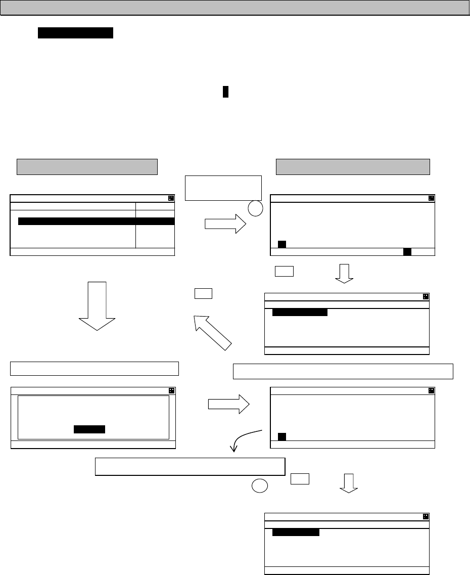
5.3.2.2 TX Tray (Viewing Transmitted Messages)
Select 2. TX TRAY at “MESSAGE” menu screen (refer to “5.3.2 MESSAGE MENU”),“TX TRAY”
screen is displayed. Transmitted and edited messages can be saved up to 10 massages in the
transmitted message list.
The listed messages can be edited and/or can be transmitted again.
Transmitted Message List
Press ENT key Press CLR key
Press SUB key
Press SUB key
Select [EXIT]
Press SUB key
Press SUB key
Select [EXIT]
Select [EDIT]
Select [DETAIL VIEW]
Sub Menu Screen
TX VIEW screen
EDIT AND TX screen Detail Information Screen
6: 64#;
$41#&%#56
,4%
*#-7;17/#47
$41#&%#56
$41#&%#56
Ť*#-7;17/#47
6':68+'9 5%4''0
*19#4';17
!
6: 64#;
57$ /'07
=
&'6#+. 8+'9
?
=
'&+6
?
=
&'.'6'
?
=
':+6
?
*#-7;17/#47
%#6')14;4176+0'
4'2.;1((
(70%6+106':6
%*#761 4'57.61-
$41#&%#56
$41#&%#56
%#6')14;5#('6;
4'2.;1((
(70%6+106':6
%*#761 64#05/+61-
'&+6 #0& 6:
(14/#6#&&4'55'&
//5+
%#6')14;4176+0'
(70%6+10
6':6
Ť
4'2.;1((
Press CLR key
If STATIC DATA is not received at the
message transmission, it is saved by
“MMSI” in the TRAY
After received STATIC DATA, it is saved
by “NAME” in the TRAY.

5-29
Press key or key in order to select a desirable message in the display list in “TX TRAY” screen,
and then press ENT key. The selected message is displayed in ”TEXT VIEW SCREEN”.
“㧖” mark in the front of a message number indicates not transmitted message.
In order to display SUB menu screen, press SUB key at the list screen or text view screen.
Select [DETAIL VIEW] and press ENT key, detail information screen is displayed with the following
information:
1. Transmitted or edited date and time with UTC.
2. FORMAT: 9 digits MMSI for “ADDRESSED”
“BROADCAST” as BROADCAST.
3. Other items (CATEGORY, FUNCTION, REPLY, CH) of message type: Refer to the above selected
TX message detail information screen.
4. ACK (Acknowledgement):
(1) Set “REPLY ON” at “ADDRESSED”, ACK display is as follows:
“ACK: OK” is displayed at received ACK.
“ACK: NG” is displayed at not received ACK.
(2) Set “BROADCAST”, its display is as follows:
“TRANSMIT OK” is displayed at succeeded transmission.
“TRANSMIT NG” is displayed at Failed Transmission.
When return to SUB menu screen, press CLR key at TX message detail information screen.
In order to edit newly a message, select [EDIT] at the selected message’s SUB menu screen, and then
the screen is switched to “EDIT AND TX” screen for message type setting.
In order to delete the selected message, select [DELETE] at the selected message’s SUB menu screen,
and then the message is deleted.
5-30
5.3.2.3 RX Tray (Viewing Received Messages)
Select 3. RX TRAY at “MESSAGE” menu screen (refer to “5.3.2 MESSAGE MENU”), “RX TRAY”
screen is displayed.
In the RX TRAY, safety related messages can be saved up to 20, others messages can be saved up to
10. Confirmation of contents and reply are performed by selecting a message in the TRAY.
When messages are received, receiving alarm sounds normally. If the message buzzer is set “OFF” in
the BUZZER setting, receiving alarm does not sound. (“Message received popup” is appeared.)
RX TRAY” Screen
Press ENT key Press CLR key
Press SUB key
Press SUB key
Select [EXIT]
Press SUB key
Press SUB key
Select [EXIT]
Select [EDIT]
Sub Menu Screen
Select [DETAIL VIEW]
EDIT AND TX Screen Detail Information screen
TEXT VIEW screen
16*'45 /'55#)'5 64#;
$41#&%#56
4 ,4%
4 ,4%
$41#&%#56
$41#&%#56
Ť
*#-7;17/#47
6':68+'9 5%4''0
*19#4';17
!
16*'45 /'55#)'5 64#;
57$ /'07
=
&'6#+. 8+'9
?
=
'&+6
?
=
&'.'6'
?
=
':+6
?
Press CLR key
'&+6 #0&6:
(14/#6#&&4'55'&
//5+
%#6')14;4176+0'
(70%6+10
6':6
Ť
4'2.;1((
If STATIC DATA is not received at the
message receiving, it is saved by
“MMSI” in the TRAY
After received STATIC DATA, it is saved
by “NAME” in the TRAY.
$41#&%#56
$41#&%#56
%#6')14;4176+0'
4'2.;1((
(70%6+106':6
%*#

5-31
Press key or key in order to select a desirable message in the list “1. SAFETY MESSAGES” tray
and “2. OTHERS MESSAGES” tray in “RX TRAY” screen, and then press ENT key. The selected
message is displayed in TEXT VIEW screen.
“㧖” mark in the front of a message number indicates an unread message.
“R” mark in the front of a message number indicates that it is a received message with reply and a reply
is not carried out at that time.
In order to display SUB menu screen, press SUB key at the list screen or text view screen.
Select [DETAIL VIEW] and press ENT key, detail information screen is displayed with the following
information:
1. Received or edited date and time with UTC
2. FORMAT: 9 digits MMSI for ADDRESSED
“BROADCAST” as BROADCAST
3. Other items (CATEGORY, FUNCTION, REPLY, CH) of message type: Refer to the above selected
RX message detail information screen.
In order to return to SUB menu screen, press CLR key at TX message detail information screen.
In order to edit newly a message such as replay, select [EDIT] at the selected message’s sub menu
screen, and then the screen is switched to “EDIT AND TX” screen for message type setting. However
the reply cannot be performed with BROADCAST, since the [EDIT] selection is reply for a receiving
“ADDRESSED” message.
In order to delete the selected message, select [DELETE] at the selected message’s sub menu screen
and then the message is deleted.
A received message with Reply: The message type of the received message is the following setting.
1. Received Message Type = FORMAT: ADDRESSED, CATEGORY: ROUTINE, FUNCTION: TEXT,
REPLY: ON
2. Received Message Type = FUNCTION: CAPABILITY INTERROGATION
In case of transmitting by CAPABILITY INTERROGATE, the contents of FI number in the received
message is shown below.
0)TEXT TELEGRAM
1)APPLICATION ACK
2)INTERROGATION FM
3)CAPABILITY INTERROGATION
4)CAPABILITY INTERROGATION REPLY
5-32
5.3.2.4 Interrogation
Select 4. INTERROGATION at “MESSAGE” menu screen (refer to “5.3.2 MESSAGE MENU”),
“INTEROGATION” screen is displayed.
An interrogation message can request information with an addressed “MMSI” specified.
a) INTERROGATION SETTINGS
Set an address and its interrogation request item in “INTERROGATION” screen.
Its interrogation request can be performed with the times in “b) INTERROGATION REQUEST ITEM
LIST” below.
Select 1. MMSII, and then the cursor move to the left end of the digit at “1. MMSI” right side.
Input the each digit of MMSI with key or key. After inputted all 9 digits, press ENT key and
then the MMSI has been set and the cursor is moves to “2. REQUEST:”.
Select 2. REUESTI, Press key or key to move the cursor to a desirable item, and then press
ENT key and the selected item has been set.
(The interrogation request item are shown in “b) INTERROGATION REQUEST ITEM LIST”
below.)
b) INTERROGATION REQUEST ITEM LIST
The following table is the list for possible interrogation request items. (“CLASS” in the list indicates a
kind of AIS on board.) (: selective)
Interrogation Item Request Note
POSN REPORT(A) Class A shipborne AIS Position Report
STATIC/VOYAGE(A) Class A shipborne AIS ship static and voyage data
SAR AIRCRAFT POS. REPORT Search and rescue aircraft AIS position report
UTC AND DATE Date and time data with UTC
POSN REPORT(B) Class B shipborne AIS Position Report
STATIC/VOYAGE(B) Class B shipborne AIS ship static and voyage data
AIDS-TO-NAVIGATION REPORT Aids to navigation AIS report
BASE STATION REPORT Base station AIS report
STATIC DATA REPORT Static data report
Caution:Check the class of the destination station at “OTHER SHIP’S DETAIL” screen
in “5.2.1.2Other Ship’s Detail Information”.
If mismatch the class, the ship does not receive the interrogation message.
SUB key
SUB / CLR key
Select [EXIT]
Responded Message Screen
INTERROGATION Screen
+06'441)#6+10
//5+
4'37'56
76%#0&'
4'57.6
+06'441)#6+10
57$ /'07
=
6:
?
=
%*'%-
?
=
%.'#4
?
=
':+6
?
+06'441)#6+10
4'57.6#%- 1-
=
1-
?
+06'441)#6+10
019 64#05/+66+0)
Select [TX]
5-33
c) SUB menu screen
Select an item in SUB menu screen, the each item operation is as follows:
[TX] 㨯㨯㨯㨯㨯㨯㨯㨯㨯㨯㨯㨯㨯㨯㨯Transmit the interrogation message
[CHECK] 㨯㨯㨯㨯㨯㨯㨯㨯㨯㨯㨯The responded message for the interrogation message is displayed.
[CLEAR] 㨯㨯㨯㨯㨯㨯㨯㨯㨯㨯㨯㨯The cursor move to “1. MSSI”.
[EXIT] 㨯㨯㨯㨯㨯㨯㨯㨯㨯㨯㨯㨯㨯㨯Return to “INTERROGATION” screen.
If there is no response to the interrogation, the replied message that corresponds to the interrogation
does not exist, therefore the screen does not switch to the response message screen,
After transmitting an interrogation message, the last line “RESULT” in the INTERROGATION screen
indicates the result of interrogation response.
Responded --------------------- RESULT㧦OK
Not responded ---------------- -RESULT㧦NG
The following is shown an example for receiving a response.
d) VIEWING RESPONDED MESSAGE
After a responded message (ACK) has been received, select [CHECK] in the SUB menu, the screen
is switched to the following “Responded Message Screen”.
In order to switch to “INTERROGATION” sub screen, press CLR key.
The contents in the responded message screen are dependent on the type of interrogation.
In case of receiving the response (example)
POSN REPORT (A) STATIC/VOYAGE (A)
BASE STATION REPORT
+06'441)#6+10
//5+
0#8+ 56#675
016 &'(+0'&
2150#%%74#%;.19
Ť
+06'441)#6+10
Ţ
21500
c
'
c
%1)
c
51)-0
*&)
c
416
c
OKP
+06'441)#6+10
0#/'
,4% /#47
%#.. 5+)00
#
+/1 01
215+6+10 5'0514
Ť
70&'(+0'&
+06'441)#6+10
Ţ
&'56+0#6+10
61-;1
'6# 016 #8#+.#$.'
.'0)6*
/
Ť
+06'441)#6+10
Ţ
$'#/
/
&4#7)*6
/
Ť
+06'441)#6+10
Ţ
5*+2 6;2'
9+)
%#4)1 6;2'
+06'441)#6+10
76%
2150#%%74#%;
*+)*
21500
c
'
c
5-34
5.3.2.5 Long Range Messages
Select 5.LONG-RANGE at “MESSAGE” menu screen (refer to “5.3.2 MESSAGE MENU”), “LONG -
RANGE” message screen is displayed.
The display/operation of a long range message is differed depending on whether “MANUAL” or “AUTO”ޕ
To select “MANUAL” or “AUTO”, refer to the “5.3.4.10 LONG-RANGE SET”.
When LONG-RANGE messages are received, “L” is displayed at the bottom line of the display. The
operation does not depend on whether "MANUAL" or "AUTO" setting is selected.
In case: other equipment is responded
LIST SORT: RANGE
Switched
automatically
After response, message is confirmed (user manual setting)
LONG – RANGE message screen
1
2
Highlighting display indicates a requested item
SUB key
SUB key
CLR key
.+56 51464#0)'
$4)
c
40)
0/
'6
O
KP 0#/'
5#46
,4%
,4%
61-;
Ť
#+%*
.10)4#0)'
57$ /'07
=
4'2.;
?
=
016 4'2.;
?
=
':+6
?
.10)4#0)'
.10)4#0)'
6*'16*'45
'37+2/'06 4'2.+'&
=
1-
?
.10)4#0)'
57$ /'07
=
':+6
?
.10)4#0)'
//5+
#0#/'%#.. 5+)0
+/1 01
$' #0& 6+/' /'55
#)'
%215+6+10
㪣
.10)4#0)'
//5+
#0#/'%#.. 5+)0
+/1 01
$' #0& 6+/' /'55
#)'
%215+6+10

5-35
a) MANUAL response condition
While “MANUAL” is set, Long Range message screen is appears automatically on any screen after
receiving a Long Range Request.
In case other equipment responds, “THE OTHERS EQUIPMENT REPLIED” is displayed.
If other equipment responds while displaying LONG-RANGE message screen, AIS displays the same
message.
Manual response operation (refer to Long Range message screen shown previously.)
- When “LONG – RANGE” message screen is displayed, the requested contents are displayed.
The operation after pressing SUB key is as follows:
- Select [REPLY], AIS transmits the response containing contents for the request and then “L” is
disappeared and the display switches to the Long Range message screen.
- Select [NOT REPLY], the AIS will transmit the message that it is not going to reply and then “L” is
disappeared and the display switches to the Long Range message screen.
- Select [EXIT] or CLR key is pressed, Switched to LIST SORT: RANGE screen.
b) AUTO response condition
While “AUTO” is set in “4. SET UP” in MAIN MENU, the reply operation is performed at background.
In this case, LONG RANGE message screen is not switched automatically.
However “L” is displayed at the bottom line of the display.
When confirming the message, the response has been already replied. Therefore after pressing
SUB key at LONG RANGE” message screen, only [EXIT] is displayed at SUB menu screen. After
EXIT is selected, “L” is disappeared.

5-36
5.3.3 Maintenance
Select 3.MAINTENANCE in “MAIN MENU” screen, “MAINTENANCE” menu screen is displayed.
It is possible to check the current status with “Maintenance” menu screen.
In order to return to MAIN MENU screen, press CLR key.
The outline of the each menu item is as follows:
1. SELF DIAGNOSIS 㨯㨯㨯Execute the self diagnosis test. (Refer to 5.3.3.1)
2. COMMUNICATION TEST 㨯㨯㨯Transmits an interrogation message and then confirms the result for
communication check.(Refer to 5.3.3.2)
3. AIS ALARM 㨯㨯㨯Displays malfunction alarms. (Refer to 5.3.3.3)
4. SENSOR STATUS 㨯㨯㨯Displays current status of sensors. (Refer to 5.3.3.4)
5. EVENT LOG 㨯㨯㨯Displays the history of power ON/OFF and so on. (Refer to 5.3.3.5)
6. SOFTWARE VERSION 㨯㨯㨯 Displays software versions installed. (Refer to 5.3.3.6)
/#+06'0#0%'
5'.(&+)015+5
%1//70+%#6+10 6'56
#+5 #.#4/
5'05'4 56#675
'8'06.1)
51(69#4'8'45+10
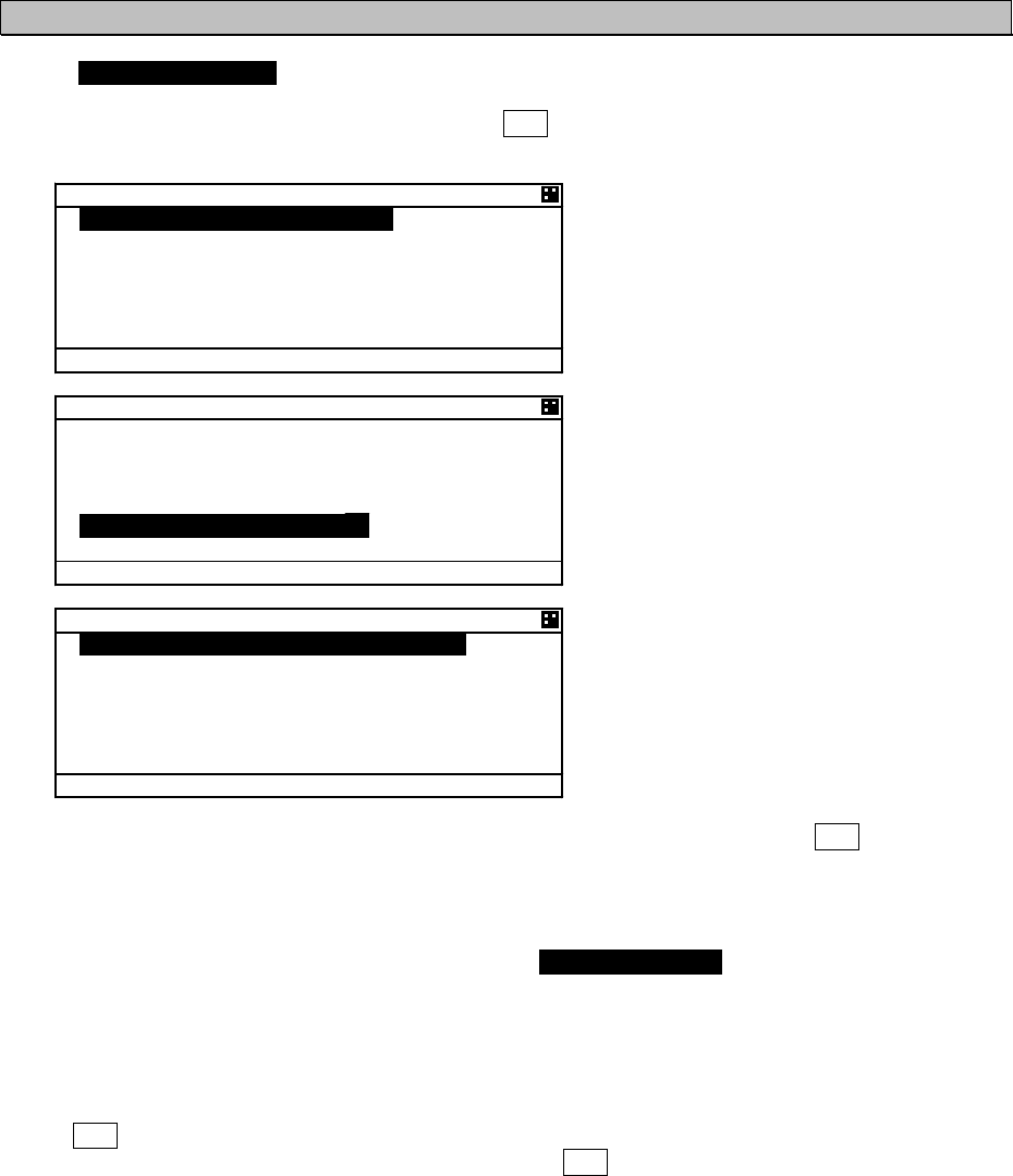
5-37
5.3.3.1. Self Diagnosis
Select 1.SELF DIAGNOSIS at “MAINTENANCE” menu screen (refer to “5.3.3 MAINTENANCE”), SELF
DIAGNOSIS screen is displayed.
In order to return to “MAINTENANCE” menu, press CLR key.
5'.( &+#)015+5
64#05210&'4
6'56 #..
=
'06
?
4'57.61-
%1061-
Ť
+06 )251-
5'.( &+#)015+5
Ţ
64:1-
251-
#06'00#
+06'40#.
%10641..'4
=
'06
?
Ť
4'57.61-
5'.( &+#)015+5
Ţ
%10641..'4 .#0
=
'06
?
4'57.61-
64#05210&'4 .1)
%10641..'4 .1)
%10641..'4 .#0 .1)
Press key or key and select the unit for performing diagnosis test and press ENT key, and then
test item for its self-diagnosis test can be selected.
a) TRANSPONDER
Select a desirable test item from the following items for 1.TRANSPONDER:
TEST ALL: Test all the units.
INT GPS: Test the internal GPS unit.
TRX: Test the transceiver unit (TRX unit).
PS: Test the PS unit is performed.
Press ENT key at a desirable test item, and the cursor is moved [ENT].
In order to perform self-diagnosis, select [ENT] and press ENT key.
Select [CANCEL], then the cursor is returned back without doing the test.
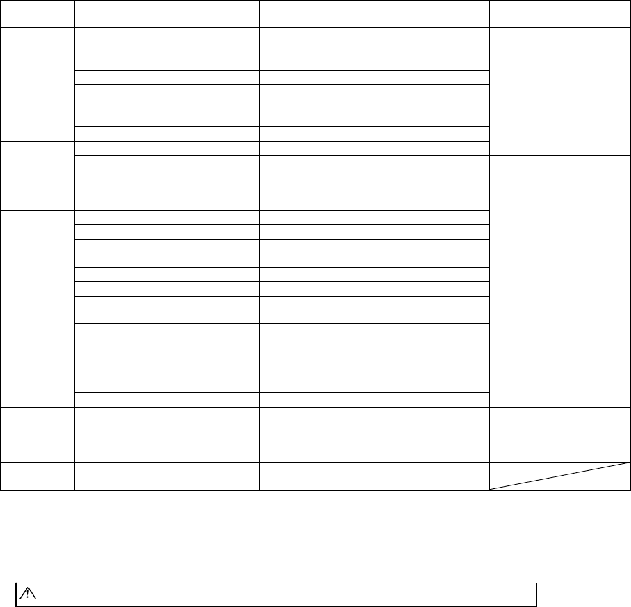
5-38
When the result of the self-diagnosis test is normal, "OK" is displayed.
The displayed result of the antenna is not a diagnosis result. It indicates the antenna terminal
during operation.
The diagnosis result of abnormal
The list of the diagnosis result of abnormal is shown in the following table.
Diagnosis
Item
Diagnosis Result Defective
Unit
Contents of Failure Corrective Action
NG CPU FROM CDJ-2483 CPU internal Flash ROM error
NG SRAM CDJ-2483 SRAM error
NG FROM CDJ-2483 Flash ROM error
NG TX DAC CDJ-2483 Transmission DA converter error
NG RX1 PORT CDJ-2483 GMSK receiver CH A input port error
NG RX2 PORT CDJ-2483 GMSK receiver CH B input port error
NG RX3 PORT CDJ-2483 DSC reception input port error
CONT
NG CDJ-2483 Multiple errors in CDJ-2483.
NG PPS CONT. CDJ-2483 Internal GPS unit error
CDJ-2483 is defective.
Replace NTE-183.
NG SAT.RCV.
CDJ-2483 Internal GPS unit receives signal from
only less than four satellites.
Check the NTE-183
installation conditions.
(*1)
INT GPS
NG CDJ-2483 Multiple errors
NG RX1 UNLK CMN-2183 GMSK receiver CH A synthesizer unlock
NG RX2 UNLK CMN-2183 GMSK receiver CH B synthesizer unlock
NG RX3 UNLK CMN-2183 DSC receiver synthesizer unlock
NG TX UNLK CMN-2183 Transmitter synthesizer unlock
NG RX1 LOOP CMN-2183 GMSK receiver CH A loop back test error
NG RX2 LOOP CMN-2183 GMSK receiver CH B loop back test error
NG RX1 RSSI CMN-2183 GMSK receiver CH A loop back test
Reception level error
NG RX2 RSSI CMN-2183 GMSK receiver CH B loop back test
Reception level error
NG RX3 RSSI CMN-2183 DSC receiver loop back test
Reception level error
NG PA CMN-2183 PA error
TRX
NG CMN-2183 Multiple errors in CMN-2183
CMN-2183 is
Defective.
Replace NTE-183.
PS
NG PS LOW
CBD-2183 Output voltage (9.8 V) error CBD-2183 is
Defective.
Replace NTE-183.
INTERNAL -- The internal antenna terminal is using ANTENNA
EXTERNAL -- The external antenna terminal is using
(*1): Check that the AIS transponder is not in the shadow of an antenna mast or other antennas.
After the installation conditions of AIS transponder is checked, wait for a while and then
perform the test again.
Caution: If malfunction is found, contact us or our agency as soon as possible.
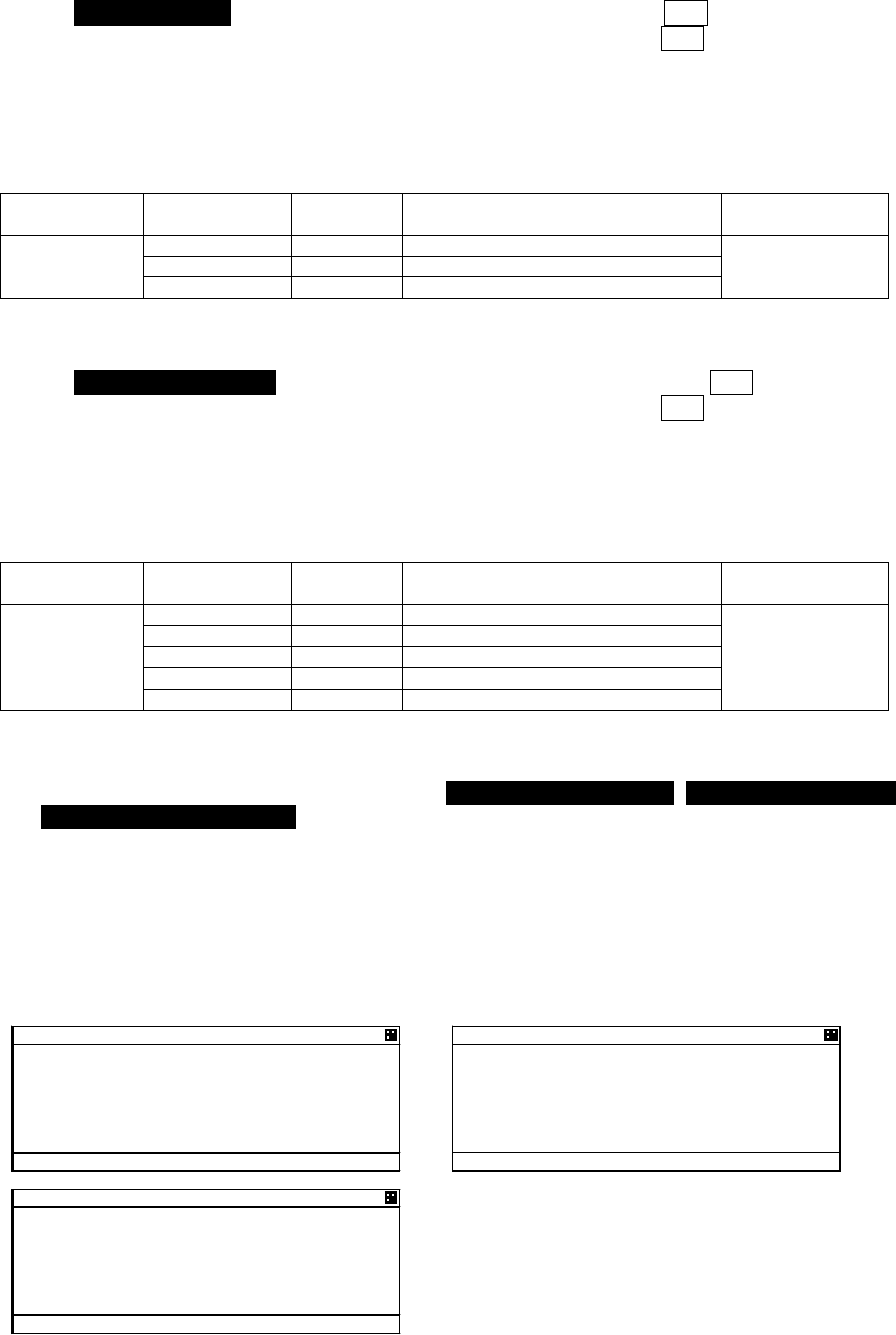
5-39
b) CONTROLLER
Select 2.CONTROLLER at “SELF DIAGNOSIS” screen, and then press ENT key.
In order to perform the self-diagnosis test, select [ENT], and then press ENT key.
If you do not perform the self-diagnosis test, press key or key and select [CANCEL], and
then the cursor is returned back without the test.
When the result of the self-diagnosis test is normal, "OK" is displayed at RESULT:.
- The diagnosis result
The list of the diagnosis result is shown in the following table.
Diagnosis Item Diagnosis
Result
Defective
Unit Contents of Failure Corrective Action
NG SRAM CDJ-2983 SRAM error
NG FROM CDJ-2983 Flash ROM error
CONTROLLER
NG CDJ-2983 Multiple errors in CDJ-2983
Replace
CDJ-2983.
c) CONTROLLER LAN
Select 3.CONTROLLER LAN at “SELF DIAGNOSIS” screen, and then press ENT key.
In order to perform the self-diagnosis test, select [ENT], and then press ENT key.
If you do not perform the self-diagnosis test, press key or key and select [CANCEL], and
then the cursor is returned back without the test.
When the result of the self-diagnosis test is normal, "OK" is displayed at RESULT:.
- The diagnosis result
The list of the diagnosis result is shown in the following table.
Diagnosis Item Diagnosis
Result
Defective
Unit Contents of Failure Corrective Action
NG CPU FROM CDJ-2983 CPU internal Flash ROM error
NG CPU DRAM CDJ-2983 CPU DRAM error
NG CPU RAM CDJ-2983 CPU RAM error
NG LAN CDJ-2983 LAN error
CONTROLLER
LAN
NG CDJ-2983 Multiple errors in CDJ-2983
Replace
CDJ-2983.
[LOG DISPLAY OF SELF DIAGNOSIS RESULT]
The past self-diagnosis results are displayed at 4.TRANSPONDER LOG,, 5.CONTROLLER LOG,,
and 6.CONTROLLER LAN LOG, .
When any of the logs are selected, the selected unit’s self-diagnosis results are displayed up to
last 20 results. Log display order is displayed from first to 20th sequentially from a new result.
Results and contents according to each diagnostic value are displayed as shown in the following
figure. In the last diagnostic time is displayed.
In addition,”--/-- --:--“ is displayed when time cannot be acquired.
Press key or key to change to next page.
%10641..'4 .1)
%10641..'41-
'
%10641..'40) 54#/
Ť'
64#05210&'4 .1)
64#05210&'40)
%1060)
+06)25
1-
Ť
%10641..'4 .#0 .1)
%10641..'4 .#0
1-
'
%10641..'4 .#0
0) 54#/
Ť'
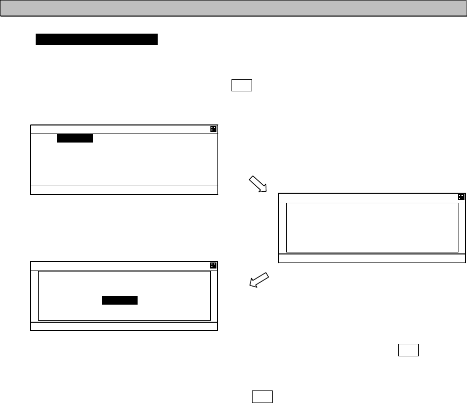
5-40
5.3.3.2. Communication Test
Select 2.COMMUNICATION TEST at “MAINTENANCE” menu screen (refer to “5.3.3 MAINTENANCE”) ,
“COMMUNICATION TEST” screen is displayed.
The address MMSI can be set automatically from nearby ships, and then perform the communication
test with others by response request.
To switch to “MAINTENANCE” menu screen, press CLR key.
In order to transmit communication confirmation contents, select [TX] and then press ENT key.
After transmitted, its responded result is displayed.
Responded --------------------- ACK: OK
Not responded ---------------- ACK: NG
Select [OK] in this Popup, and then press ENT key, and the screen is switched to
“COMMUNICATION TEST” screen.
Also “RESULT:“ on the bottom line in “COMMUNICATION TEST” screen is displayed the response
result after transmission.
Responded --------------------- RESULT: OK
Not responded -----------------RESULT: NG
Select [TX]
%1//70+%#6+106'56
019 64#05/+66+0)
%1//70+%#6+106'56
#%- 1-
=
1-
?
%1//70+%#6+10 6'56
=
6:
?
=
%#0%'.
?
&'56+0#6+10
//5+
4'57.6
Communication test
screen
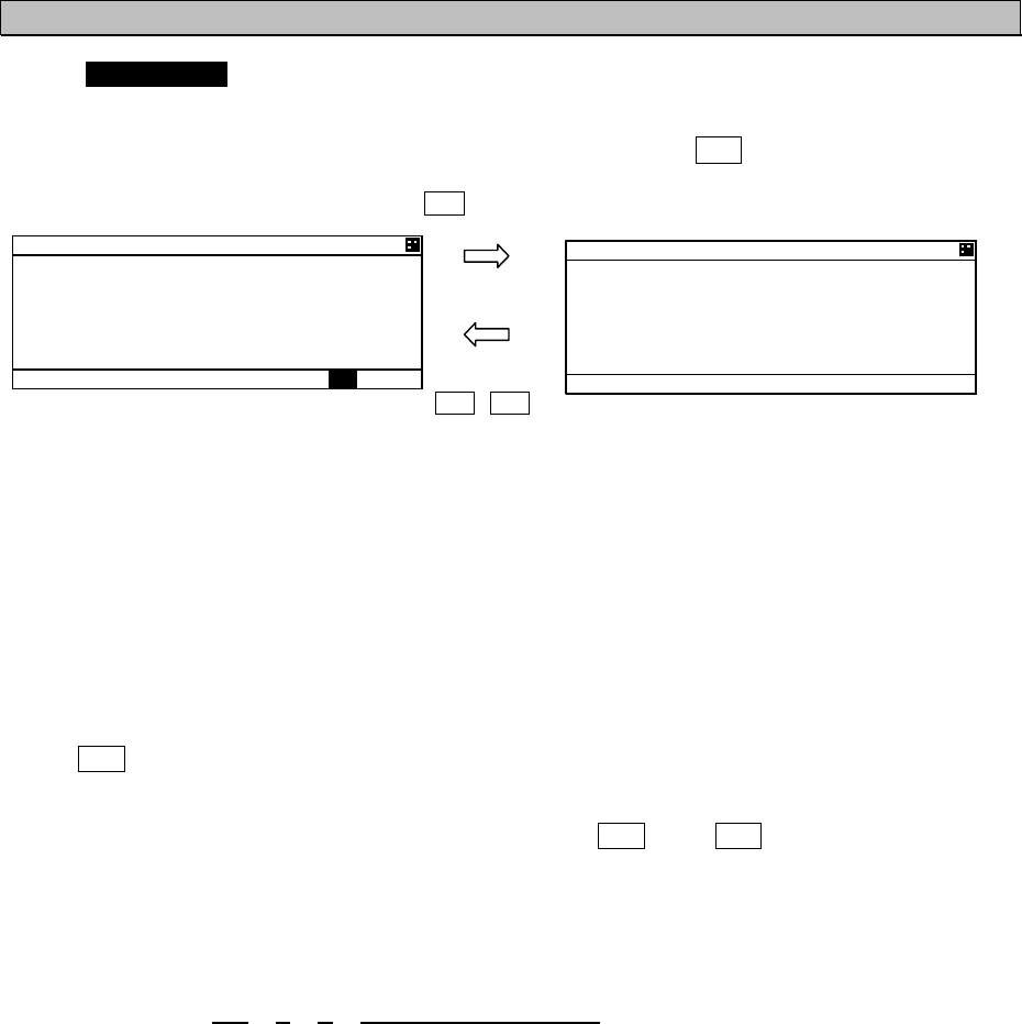
5-41
5.3.3.3. AIS Alarm
Select 3.AIS ALARM at “MAINTENANCE” menu screen (refer to “5.3.3 MAINTENANCE”), “AIS
ALARM” confirmation screen is displayed.
“ALARM HISTORY” screen can be displayed up to 50 from last defective alarms during the operation.
When the display is switched to “MAINTENANCE” menu screen, press CLR key.
1. Current Alarm status
A current occurring alarm list is displayed in “ALS ALARM” screen.
- When the AIS alarm doesn't occur, “NO DATA” is displayed.
- When alarms are occurring and “” mark is displayed on the bottom line, this means that there are
contents in the next page. When there is nothing in the next page, “” mark is not displayed on the
bottom line.
- In order to see the next page, press key or key.
The screen displays consecutive items, press key or key to see next items.
2. Alarm history
When SUB key is pressed at “ALS ALARM” screen, the screen is switched to “ALARM HISTORY”
screen.
Up to 50 occurred and restored alarms can be confirmed.
When the display is switched to “ALS ALARM” screen, press SUB key or CLR key.
- When “” mark is displayed on the bottom line, This means that there are contents in the next page,
Therefore press key or key to see next.
- Time of all occurred alarm and all their restorations is displayed with UTC.
If the time cannot to be acquired, ” --/--/-- --:-- “ is displayed there.
- A description of alarm display is shown below.
Alarm contents: 035, V, A, no valid ROT information
(1) (2) (3) (4)
(1): The alarm number (refer to the next page)
(2): The alarm condition -> “V”: Alarm is restored
“A”: Alarm is occurring
(3): Not used
(4): Alarm’s description text (refer to the following table)
SUB key
SUB / CLR key
#+5 #.#4/
#8 ':6'40#. '2
(5 .156
㪘㪣
#.#4/ *+5614;
#8 ':6'40#.
'2(5 .156
8# 01 8#.+&
Ť416 +0(1/#6+10

5-42
Lists of failure alarms are as follows:
Alarm List
Alarm No. Alarm’s description text The contents of unusual detection
001 TX MALFUNCTION Unusual detection at the transmission.
002 ANTENNA VSWR EXCEEDS LIMIT Unusual detection of antenna output.
003 RX CHANNEL 1 MALFUNCTION Unusual detection of Rx channel 1.
004 RX CHANNEL 2 MALFUNCTION Unusual detection of Rx channel 2
005 RX CHANNEL 70 MALFUNCTION Unusual detection of receiving DSC.
006 GENERAL FAILURE Detected a general failure
008 MKD CONNECTION LOST Detected the connection between CONTROLLER and
TRANSPONDER is lost.
010 NAVSTATUS INCORRECT Mismatch information of navigation status.
014 ACTIVE AIS-SART AIS-SART signal has received.
025 EXTERNAL EPFS LOST No information of sensor position from external.
026 NO SONSOR POSITION IN USE No information of sensor position.
029 NO VALID SOG INFORMATION No information of SOG.
030 NO VALID COG INFORMATION No information of COG.
032 HEADING LOST/INVALID No information of HEADING.
035 NO VALID ROT INFORMATION No information of ROT.
051 TX POWER DOWN Detected TX power is down.
052 TX POWER SUPPLY ERROR Unusual detection of power supply voltage at TX.
053 POWER SUPPLY ERROR Unusual detection of power supply voltage.
054 PA CURRENT ERROR Unusual detection of TX current.
055 PA TEMP ERROR Detected the PA temperature is warming up at TX.
056 TX POWER TOO LOW Detected the TX power is lower than Spec.
057 VR ERROR Unusual detection of TX output.
058 TX STOP INTERRUPT Unusual detection of transmission (forced outage) with TX
watch circuit.
059 TX POWER TOO HIGH Detected the TX power is higher than Spec.
060 TX PLL UNLOCK Detected the TX PLL is unlocked.
062 PROGRAM FLASH MEMORY ERR Unusual detection of check sum in the ROM with CPU.
063 DATA FLASH MEMORY ERR Unusual detection of check sum in the other ROM.
064 MKD CONNECTION LOST No response from the transponder. 㧔detected by
CONTROLLER㧕
065 SSD MISMATCH Mismatch static information between transponder and
CONTROLLER.
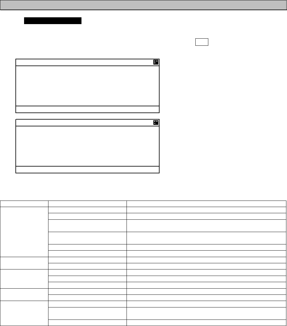
5-43
5.3.3.4. Sensor Status
Select 4.SENSOR STATUS at “MAINTENANCE” menu screen (refer to “5.3.3 MAINTENANCE”),
“SENSOR STATUS” screen is displayed.
Also the next page is displayed with obtaining information of sensor device (ID) and command status.
When the display is switched to “MAINTENANCE” menu screen, press CLR key.
5'0514 56#675
215+6+10
':6'40#. )055
76% %.1%-+075'
51)
%1)':6'40#.
*'#&+0)8#.+&
Ť416+075'
5'0514 56#675
Ţ+& %1//#0&
2150)2 4/%
51) )2 4/%
%1) )2 4/%
*&) *' *&6
416 6+ 416
Sensor status displays are as follows:
Sensor Type Display Explanation
EXTERNAL DGNSS Data is obtained from the external GPS (high accuracy).
EXTERNAL GNSS Data is obtained from the external GPS (low accuracy).
INT DGNSS(BEACON) Correction data is obtained from the beacon receiver and the
internal GPS is used (high accuracy).
INT DGNSS(MSG.17) Correction data is obtained from the base station and the internal
GPS is used (high accuracy).
INTERNAL GNSS Data is obtained from the internal GPS (low accuracy).
POSITION
NO SENSOR No data is available.
LOST The internal GPS is not synchronized with PPS.
UTC CLOCK IN USE The internal GPS is synchronized with PPS.
EXTERNAL Data is obtained from the external equipment.
INTERNAL Data is obtained from the internal GPS.
SOG/COG
NO SENSOR No data is available.
VALID Data is obtained from the external equipment.
HEADING INVALID No data is available.
IN USE Data is obtained from the rate-of-turn indicator.
OTHER SOURCE Data is obtained from the equipment other than the rate-of-turn
indicator.
ROT
NO SENSOR No data is available.
The detail of sensor ID is shown at next page.
About the detail of command, refer to “8.3.4 Supported interface sentences”.
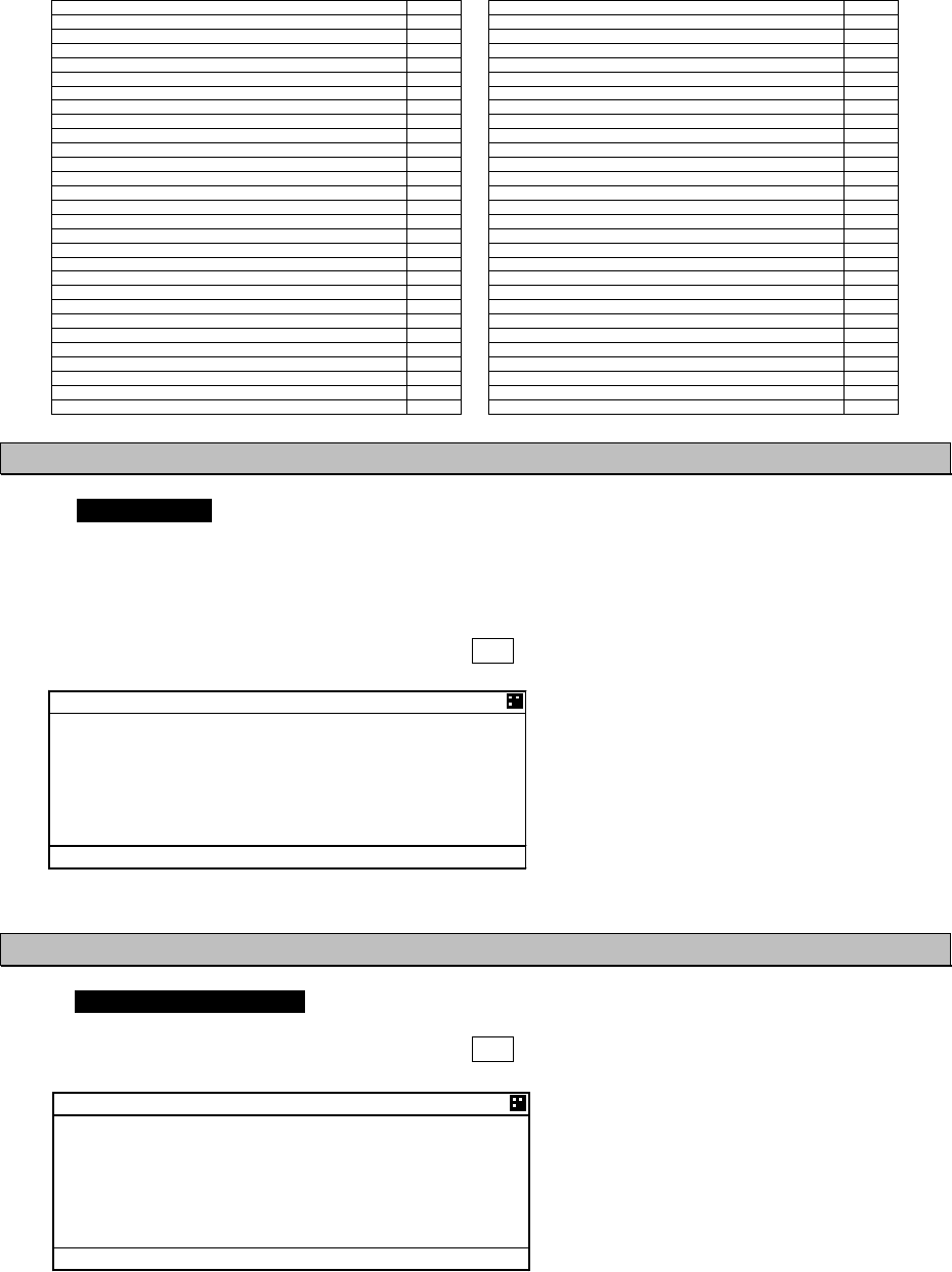
5-44
ID displayed at SENSOR STATUS is shown below list.
Talker device ID Talker device ID
Heading/track controller (autopilot) general AG Heading sensors: gyro, non-north seeking HN
magnetic AP Hull door controller/monitoring system HD
Automatic identification system AI Hull stress monitoring HS
Bilge system BI Integrated instrumentation II
Bridge navigational watch alarm system BN Integrated navigation IN
Communications: digital selective calling (DSC) CD LORAN: LORAN-C LC
Communications: data receiver CR Navigation light controller NL
Communications: satellite CS Proprietary code P
Communications: radio-telephone (MF/HF) CT Radar and/or radar plotting RA
Communications: radio-telephone (VHF) CV Propulsion machinery including remote control RC
Communications: scanning receiver CX Sounder, depth SD
Direction finder DF Steering gear/steering engine SG
Duplex repeater station DU Electronic positioning system, other/general SN
Electronic chart system (ECS) EC Sounder, scanning SS
Electronic chart display and information system (ECDIS) EI Turn rate indicator TI
Emergency position indicating radio beacon (EPIRB) EP Microprocessor controller UP
Engine room monitoring system ER Velocity sensors: Doppler, other/general VD
Fire door controller/monitoring system FD Velocity sensors: speed log, water, magnetic VM
Fire extinguisher system FE Velocity sensors: speed log, water, mechanical VW
Fire detection system FR Voyage data recorder VR
Fire sprinkler system FS Watertight door controller/monitoring system WD
Galileo positioning system GA Water level detection system WL
Global positioning system (GPS) GP Transducer YX
GLONASS positioning system GL Timekeeper, time/date: atomic clock ZA
Global navigation satellite system (GNSS) GN Timekeeper, time/date: chronometer ZC
Heading sensors: compass, magnetic HC Timekeeper, time/date: quartz ZQ
Heading sensors: gyro, north seeking HE Timekeeper, time/date: radio update ZV
Heading sensors: fluxgate HF Weather instrument WI
5.3.3.5. Event Log
Select 5.EVENT LOG at “MAINTENANCE” menu screen (refer to “5.3.3 MAINTENANCE”), “EVENT
LOG” screen is displayed and Event log (e.g. Power ON/OFF) can be displayed up to 20 events.
The stored logs are shown below.
1. POWER ON/OFF
2. SILENT MODE ON/OFF
3. MALFUNCTION ON
To switch to “MAINTENANCE” menu screen, press CLR key.
When “” or “” mark is displayed at the left side, Press key or key to see next.
5.3.3.6. Software Version
Select 6.SOFTWARE VERSION at “MAINTENANCE” menu screen (refer to “5.3.3 MAINTENANCE”),
“SOFTWARE VERSION” screen is displayed.
To switch to “MAINTENANCE” menu screen, press CLR key.
'8'06 .1)
219'4 10
219'4 1((
219'4 10
Ť
51(69#4' 8'45+10
64#05210&'4
%106
%10641..'4
%106
.#0
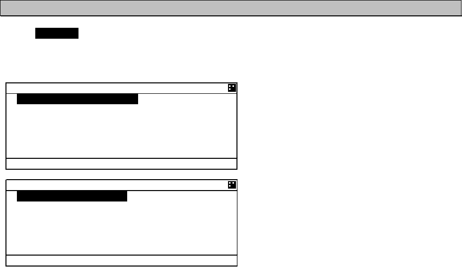
5-45
5.3.4 Set up Menu
Select 4.SET UP at “MAINMENU” menu screen, “SET UP” screen is displayed.
In this SETUP MENU, The controller display function and the operation of transponder can be set.
The outline of each menu is as follows.
1.DATE&TIME㨯㨯㨯㨯㨯㨯㨯㨯㨯㨯㨯㨯㨯㨯㨯㨯㨯㨯㨯㨯㨯Select display’s setting (e.g. local time) (refer to 5.3.4.1)
2.MY CONTROLLER㨯㨯㨯㨯㨯㨯㨯㨯㨯㨯㨯㨯㨯㨯㨯Set LCD, buzzer and USER key function (refer to 5.3.4.2)
3.REGIONAL CHANNEL㨯㨯㨯㨯㨯㨯㨯㨯㨯㨯㨯㨯㨯Regional channel setting (refer to 5.3.4.3)
4.PWR REDUCT㨯㨯㨯㨯㨯㨯㨯㨯㨯㨯㨯㨯㨯㨯㨯㨯㨯㨯㨯Set Low power transmission(1w) (refer to 5.3.4.4)
5.GROUP SHIP㨯㨯㨯㨯㨯㨯㨯㨯㨯㨯㨯㨯㨯㨯㨯㨯㨯㨯㨯Register group ships(up to 10 ships) (refer to 5.3.4.5)
6.CHANNEL/POWER SET㨯㨯㨯㨯㨯㨯㨯㨯㨯Select channels and power (refer to 5.3.4.6)
7.PASSWORD㨯㨯㨯㨯㨯㨯㨯㨯㨯㨯㨯㨯㨯㨯㨯㨯Change password (e.g. power off, channel/POWER) (refer to 5.3.4.7)
8.POSN DISP SET㨯㨯㨯㨯㨯㨯㨯㨯㨯㨯㨯㨯㨯㨯㨯㨯Select the display type of position (lat, long) (refer to 5.3.4.8)
9.SART TEST SET㨯㨯㨯㨯㨯㨯㨯㨯㨯㨯㨯㨯㨯㨯㨯㨯AIS SART test signal display (refer to 5.3.4.9)
10.LONG-RANGE SET㨯㨯㨯㨯㨯㨯㨯㨯㨯㨯㨯㨯Long range setting (auto response, channel) (refer to 5.3.4.10)
11.SILENT MODE㨯㨯㨯㨯㨯㨯㨯㨯㨯㨯㨯㨯㨯㨯㨯㨯Prohibition of transmission (refer to
5.3.4.11)
12.CCRP SET㨯㨯㨯㨯㨯㨯㨯㨯㨯㨯㨯㨯㨯㨯㨯㨯㨯㨯㨯In case of using CCPR, set the external position (refer to 5.3.4.12)
(OPTION: planning to deal with)
13.NSK UNIT㨯㨯㨯㨯㨯㨯㨯㨯㨯㨯㨯㨯㨯㨯㨯㨯㨯NSK initial setting and confirmation of unit condition (refer to 5.3.4.13)
5'672
'6+/'
/; %10641..'4
4')+10#. %*#00'.
294 4'&7%6014/#.
)4172 5*+2
Ť%*#00'.
219'4 5'6
5'6 72
Ţ2#55914&
2150 &+525'61((
5#46 6'56 5'61((
.10)4#0) 5'6
5+.'06 /1&'1((
%%42 5'61((
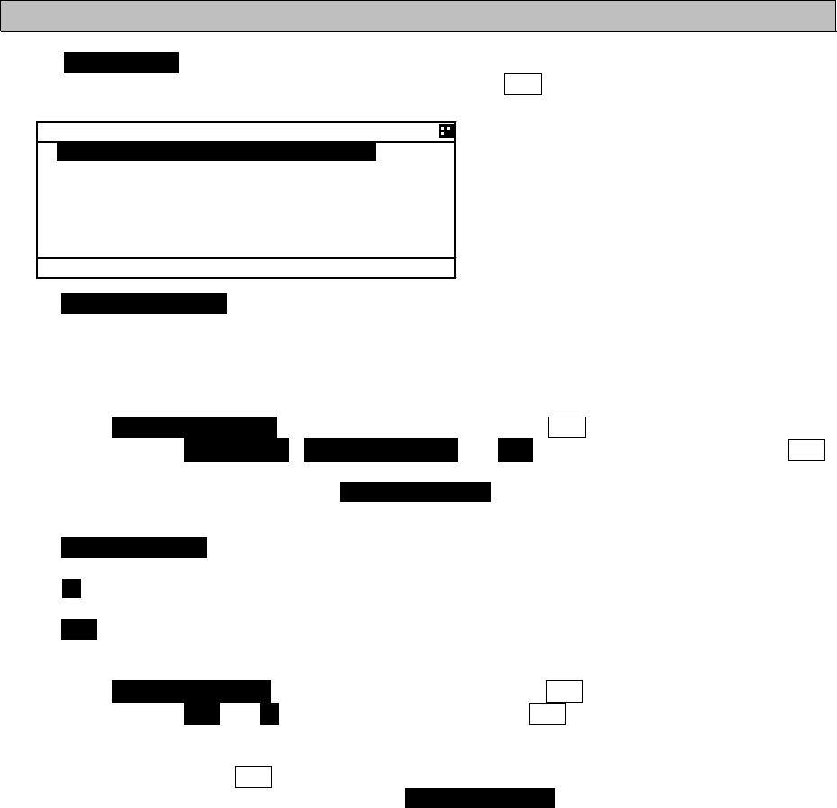
5-46
5.3.4.1 Display Setting of Date and Time (DATE
㧒
TIME)
Select 1.DATE&TIME at “MAINMENU” menu screen, “DATE&TIME” screen is displayed.
When the display is switched to “SET UP” menu screen, press CLR key.
When 1.POSN&TIME DISP is selected, Displayed contents of POSITION/TIME can be set.
1.
The content can be select between POSN&TIME, POSN&COG&SOG and OFF.
If “OFF” is selected, when you push DISP key, POSN&TIME screen is not displayed.
Setting procedure
1. Select 1.POSN&TIME DISP at DATE&TIME screen and press ENT key
2. Select between POSN&TIME㧘POSN&COG&SOG and OFF with key or key and press ENT
key.
3. After selecting, the cursor moves to 2. DISPLAY FORM.
When 2.DISPLAY FORM is selected, Display of local time and the difference in time can be set.
When LT is selected, POSN&TIME screen displays “LT” and the displayed time is compensated by the
difference.
When UTC is selected, the screen displays ”UTC” and the time is standard time.
Setting procedure
1. Select 2. DISPLAY FORM at DATE&TIME screen and press ENT key
2. Select between UTC and LT with key or key and push ENT key
3. When LT is selected, the cursor move to first digit of DIFF and then input the difference.
The difference in time can be inputted between -12:00 to +12:00.
After last digit set, push ENT key.
When “UTC” is selected, the cursor moves to 2. DISPLAY FORM.
'6+/'
21506+/' &+52
21506+/'
&+52.#; (14/76%
.6 &+((
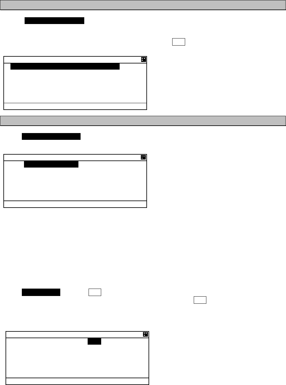
5-47
5.3.4.2 My Controller
Select 2.MY CONTROLLER at “MAIN MENU” menu screen, “MY CONTROLLER” screen is
displayed.
In this menu, LCD display setting, buzzer ON/OFF and assignment of USER key can be set.
When the display is switched to “SET UP” menu screen, press CLR key.
a) LCD Adjustment
Select 1.LCD ADJUSTMENT, LCD adjustment screen is appeared.
In this menu, Items concerned with display can be set.
.%& #&,756/'06
%1064#56
&+//'4
5%4''0 5#8'4
$#%- .+)*6
12'4#6+109*+6'
#.#4/ 14#0)'
The outline of the each menu is as follows.
1. CONTRAST㨯㨯㨯㨯㨯㨯㨯㨯Set contrast value
2. DIMMER㨯㨯㨯㨯㨯㨯㨯㨯㨯㨯㨯Display the DIMMER adjustment screen
3. SCREEN SAVER㨯㨯㨯㨯Display the time setting menu of turning off the back light
4. BACK LIGHT㨯㨯㨯㨯㨯㨯㨯Set the color of back light
1. CONTRAST
Set the current contrast.
Select 1.CONTRAST and push ENT key and then the contrast can be adjusted.
Press key or key to adjust the shade. After the adjustment, press ENT key and the setting is
saved.
The adjustment value “1” is the darkest and “13” is the lightest.
.%& #&,756/'06
%1064#56
&+//'4
5%4''0 5#8'4
$#%- .+)*6
12'4#6+109*+6'
#.#4/ 14#0)'
/; %10641..'4
.%& #&,756/'06
5170&
75'4 -';#55+)0
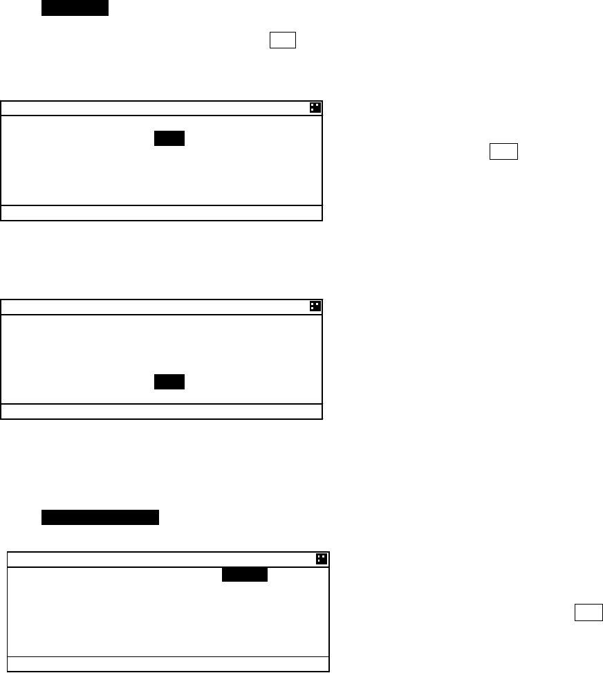
5-48
2. DIMMER
Select 2.DIMMER, DIMMER adjustment screen is displayed.
(The cursor move to the right of ”MAXIMUM”.)
The dimmer is adjusted for each pressing of DIM key, and these levels are defined by 4 stages (MAX,
TYPICAL, MIN, OFF). In this menu, The value of MAX, TYPICAL, MIN can be set. And set the
increasing value in case of alarm.
When the cursor is on the right of “MAXIMUM”,
the value can be adjusted. Press key or
key to adjust it and press ENT key and then the
cursor moves to the right of“TYPICAL”.
The value of MAXIMUM㧘TYPICAL and
MINIMUM can be set between 1 to 13.
e.g.㧕If “MAXIMUM” value is set to 9, the “TYPICAL” value can be set less than 9. The "MINIMUM" value
is set to a value below the "TYPICAL" value as shown in the above example.
The ALARM value can be set between +1 to +9.
In the case of an alarm, the current dimmer
setting is altered by the value set here.
As shown in the above example, when a value of 7 is set for TYPICAL, then the dimmer value is set to
9 during the alarm condition.
3. SCREEN SAVER
Select 3.SCREEN SAVER, SCREEN SAVER setting menu is displayed.
In this menu, the time to turn off the LCD light after no operation condition can be set.
Select from OFF or ON.
If there is no need for this function, Select
“OFF” with key or key and press ENT key,
and then TIMER value is changed into “00”
automatically.
&+//'4
&+//'4
/#:+/7/
6;2+%#.
/+0+/7/
#.#4/
&+//'4
&+//'4
/#:+/7/
6;2+%#.
/+0+/7/
#.#4/
5%4''0 5#8'4
5%4''0 5#8'41((
6+/'4
OKP
Ť
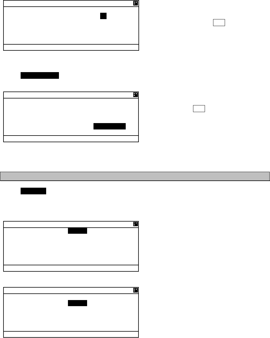
5-49
Select “ON”, the cursor move to TIMER value.
Set the value between 00 and 60 (minutes) with
key or key and press ENT key.
4. BACK LIGHT
Select 4.BACK LIGHT, the color of back light can be changed.
In this menu, the back light can be selected.
Select WHITE or ORANGE at “OPERATION”
with key or key.
After setting, press ENT key, and then the
cursor move to the right side of “ALARM”.
Take the same procedure.
b) Sound
Select 2.SOUND, Buzzer setting screen is appeared.
In this menu, Items concerned with the buzzer can be set.
Select from ON (sounds the buzzer) and OFF and set each item with key or key.
If “OFF” is selected at “BUZZER”, all 4 settings
are changed into OFF.
When “ON” is selected at “BUZZER”, select
from ON and OFF and set each of items.
MESSAGE 㨯㨯㨯㨯㨯㨯㨯㨯㨯㨯㨯 In case of receiving message
GUARD ZONE ALM 㨯㨯㨯 In case some ships enter in the guard zone range
ALARM 㨯㨯㨯㨯㨯㨯㨯㨯㨯㨯㨯㨯㨯㨯 In case some failure alarm occur
CLICK 㨯㨯㨯㨯㨯㨯㨯㨯㨯㨯㨯㨯㨯㨯㨯 In case AIS is operated with keys
.%& #&,756/'06
%1064#56
&+//'4
5%4''0 5#8'4
$#%- .+)*6
12'4#6+109*+6'
#.#4/ 14#0)'
Ť
5170&
$7<<'4 1((
/'55#)'1((
)7#4& <10'#./1((
#.#4/1((
%.+%-1((
Ť
5170&
$7<<'4 10
/'55#)'1((
)7#4& <10'#./1((
#.#4/1((
%.+%-1((
Ť
5%4''0 5#8'4
5%4''0 5#8'410
6+/'4
OKP
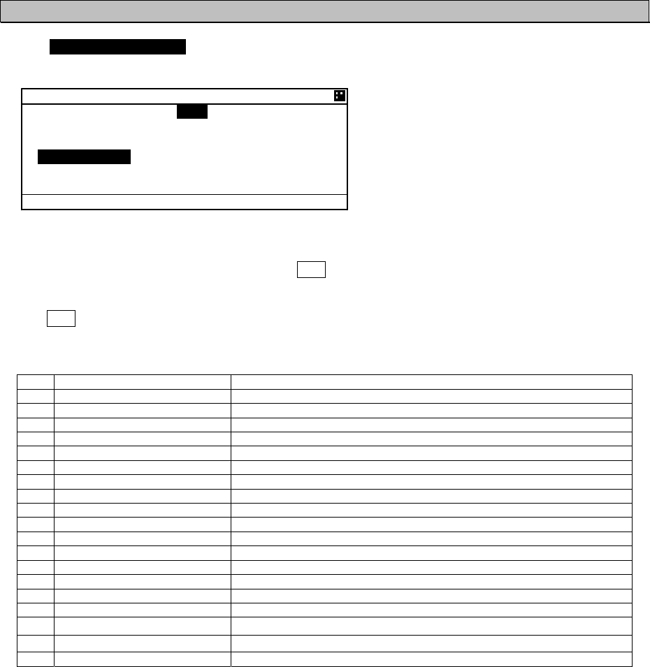
5-50
c) User Key Assign
Select 3.USER KEY ASSIGN, User key assignment screen is displayed.
In this menu, Assignment to USER key can be set.
When USER KEY ASSIGN screen is displayed, the cursor is on the current setting.
Select the item with key or key and press ENT key to decide.
When “ ” mark is displayed on the left side, it means selection items continue.
Press CLR key, and then return to MY CONTROLLER MENU.
Refer to the lists following to select item
No
items Explanation
1 GRAPHIC DISPLAY Displays GRAPHIC screen
2 OWN SHIP’S DETAIL1 Displays OWN SHIP’S DETAIL 1 screen
3 OWN SHIP’S DETAIL2 Displays OWN SHIP’S DETAIL 2 screen
4 POSN&TIME Displays POSN&TIME screen
5 VOYAGE DATA Displays VOYAGE DATA menu
6 MESSAGE Displays MESSAGE menu
7 MAINTENANCE Displays MAINTENANC menu
8 SET UP Displays SETUP menu
9 SELF DIAGNOSIS Displays SELF DIAGNOSIS menu
10 COMMUNICATION TEST Displays COMMUNICATION TEST menu
11 AIS ALARM Displays ALARM INFORMATION screen
12 SENSOR STATUS Displays SENSOR STATUS menu
13 MY CONTLOLLER Displays MY CONTLOLLER menu
14 REGIONAL CHHANNEL Displays REGIONAL CH SETTING
15 PASSWORD Displays PASSWORD screen
16 SART TEST SET Displays SART TEST MODE SET menu
17 LONG-RANGE SET Displays LONG RANGE SET menu
18 SILENT MODE Displays SILENT MODE setting
19 NON USE No operation by USER key
75'4 -'; #55+)0
75'4 -';
Ţ
/'55#)'
/#+06'0#0%'
5'6 72
5'.( &+#)015+5
Ť
%1//70+%#6+10 6'56
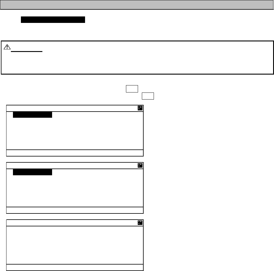
5-51
5.3.4.3 Regional Channel
Select 3.REGIONAL CHANNEL, Regional channel setting screen is displayed.
Set the channel management information in the specified area.
Up to 8 channel management settings can be registered.
Caution:
When setting the regional channel management, input the information correctlybased on the
administration. Incorrect setting causes a failure of the communication with other vessels and coast
radio station.
Select the item with key or key and Press ENT key, the item can be set.
When the display is switched to SET UP menu, press CLR key.
In addition to the channel management information by this AIS
AIS communication from a coast station to this ship
AIS communication from a coast station to all ships
DSC communication from a coast station
Channel management by other equipment through the connection port.
4')+10#. %*#00'.
%* #
%* $
6:
4: /1&' %* #$
6:
4: 6:
4:
6: 219'4*+)*
Ť
<10' 5+<'0/
4')+10#. %*#00'.
Ţ
#4'#
c
æ
0'
c
æ
#4'#
c
æ
59
c
æ
Ť
4')+10#. %*#00'.
Ţ
5174%'
//5+
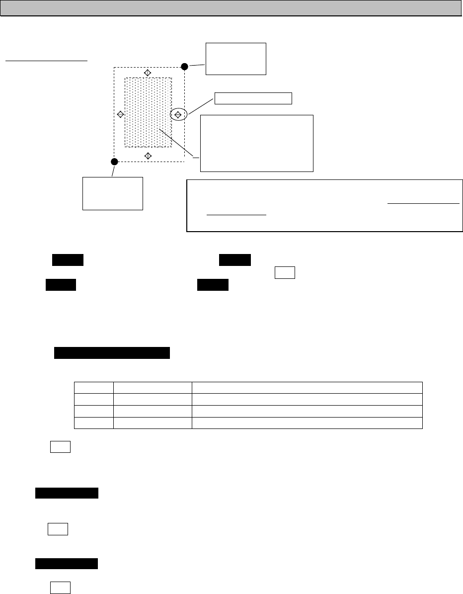
5-52
a) Setting change of each item
Each item settings are as follows
The area of setting
1. CH A
2. CH B
Item 1 and 2 are setting of the channel numbers.
Select 1.CH A, CH A can be changed. Select 2.CH B CH B can be changed.
Input the channel number with key or key and press ENT key. And then the setting is valid.
After 1.CH A setting, the cursor move to 2.CH B. The setting procedure is same as CH A.
3. TX/RX MODE
Set the CH A/CH B (specified at item 1,2) TRX mode to “TX/RX” or “RX”.
If “TX/RX” is selected, the setting is changed into transmitter-receiver mode. If “RX” is selected, the
setting is changed into receiver mode.
Select 3. TX/RX MODE CH A,B with key or key and select the CH A/B mode from the
selection (shown in the table below).
Order Selection Dialog
1 TX/RX, TX/RX CH A and B set transmitter- receiver mode
2 TX/RX, RX CH A set transmitter-receiver, CH B set receiver
3 RX, TX/RX CH A set receiver, CH B set transmitter-receiver
Press ENT key and confirm the setting.
It is not acceptable that Sets both CH A and CH B to “RX”.
4. TX POWER
Select 4. TX POWER, transmission power can be set.
Select the transmission power from “HIGH” and “LOW” with key or key.
If “HIGH” is selected, the power is set 12.5W, if ”LOW” is selected, the power is set 1W.
Press ENT key and confirm the setting.
5. ZONE SIZE
Select 5. ZONE SIZE, zone size width can be input.
Press key or key to input the zone size width. (Input range; from 1NM to 8NM.)
Press ENT key and confirm the input.
#4'#0'
0q’
'q’
#4'#59
0q’
'q’
<10'5+<'0/
%*#
%*$
6:4:/1&'6:4:6:4:
%*#%*$
6:219'4*+)*
x The set range of coordinates is the distance between
AREA (NE) and AREA (SW) and it is over 20NM and
under 200NM
x The setting area is within 500NM from own ships position.

5-53
6. AREA (NE)
Select 6. AREA and set “NE” by inputting latitude and longitude.
If set by north latitude, select “N” with key or key. If set by south latitude, select “S”, and then
press ENT key and set.
The cursor moves to the latitude input line, set the figure with key or key and press ENT key
to determine. (refer to “5.2.5 numerical input method”)
After determination of the latitude, the cursor move to longitude input line.
If set by east longitude, select “E”, If set by west longitude, select “W” and then input the longitude.
The procedure is same as latitude.
These setting ranges are shown as follows, latitude from 0°00.00’ to 89°59.99’ and longitude
0°00.00’ to 179°59.99’.
Press ENT key and determine the input.
Press CLR key, the cursor return to previous digit.
7. AREA (SW)
Select 7. AREA and set “NE” by inputting latitude and longitude.
The setting procedure is same as “6. AREA (NE)”.
After setting of item from 1 to 7, carry out the “CHECK” of the setting (as shown nest page)
8. The source of regional channel setting㧔SOURCE/MMSI/UTC㧕
This item “8.SOURCE/MMSI/UTC” displays the channel setting information.
This is display only, settings and selection are not available.
These contents are shown below.
SOURCE… The means of setting
The regional setting is managed by 5 types.
1. ADDRESSED MSG.22 : Channel management to this ship
2. BROADCAST MSG.22 : Channel managements to all ships
3. CH ASSIGNMENT : Managed by other equipments connected with NQE-5183
4.DSC 70CH TELCOM : Channel management by DSC telecommand
5.MANUAL INPUT : Channel management by oneself
MMSI…… MMSI number of the station which operates the setting indication.
UTC………UTC time AIS received the indication
If CLR key is selected, the display is switched to SET UP menu.
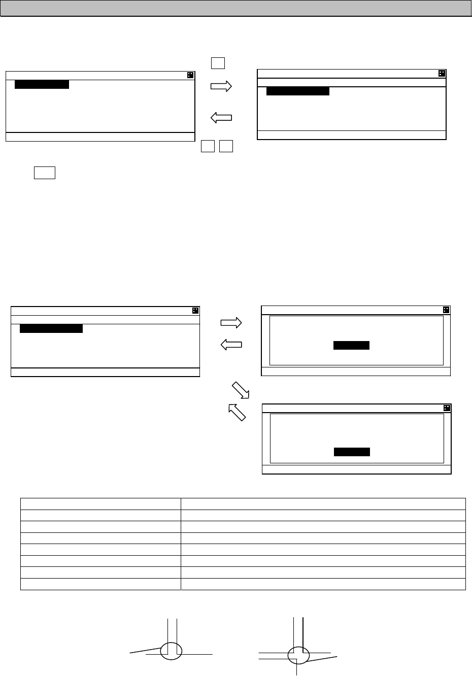
5-54
b) Check of the setting
Check the regional management setting whether it is based on the restriction or not.
If there are no errors, the setting can be saved
Press SUB key at the setting screen, SUB menu screen is displayed.
CHECK 㨯㨯㨯㨯㨯 Check the setting whether it is based on the restriction or not
SAVE 㨯㨯㨯㨯㨯㨯㨯 Save the setting, in case there are no problems.
LIST 㨯㨯㨯㨯㨯㨯㨯㨯 See the saved data (up to 8 setting)
CLEAR 㨯㨯㨯㨯㨯㨯 Clear the contents that is being set
EXIT 㨯㨯㨯㨯㨯㨯㨯㨯 Leave the SUB menu and return to SET UP menu
Select [CHECK] and push ENT key, the popup screen which shows the result is appeared.
Result of checking
Indication note
OK [SAVE] can be selected
NG 20NM>AREA,AREA>200NM The range is under 20NM or over 200NM.
NG AREA CORNER ERROR(*1) Each of the distances of 3 area’s corners is within 8NM.
NG AREA 500NM OVER Set the area separated 500NM from own ship’s location.
NG CHANNEL ERROR Set by invalid channel
NG OTHER ERROR Set by other invalid matters
NG OVERTIME ERROR No response from transponder
(*1)㧦In case of the condition below, AREA CORNER ERR is appeared.
㧦×㧦
57$MG[
#TGC #TGC #TGC #TGC
0QCTGC 0GYUGVVKPI
CTGC
9KVJKPPOGCEJ CTGC’U EQTPGT
YKVJKPPOGCEJ
1-UETGGP
0)UETGGP
57$%.4MG[
4')+10#. %*#00'.
%* #
%* $
6:
4: /1&' %* #$
6:
4: 6:
4:
6: 219'4*+)*
Ť
<10' 5+<'0/
4')+10#. %*#00'.
57$ /'07
=
%*'%-
?
=
5#8'
?
=
.+56
?
=
%.'#4
?
=
':+6
?
4')+10#. %*#00'.
57$ /'07
=
%*'%-
?
=
5#8'
?
=
.+56
?
=
%.'#4
?
=
':+6
?
4')+10#. %*#00'.
%*'%- 4'57.61-
=
1-
?
4')+10#. %*#00'.
0) 0/ #4'#
#4'#0/
=
1-
?
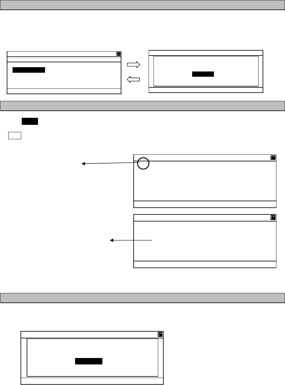
5-55
4')+10#. %*#00'.
Ţ%* #
%* $
6:
4: /1&'
#$ 4: 6:
4:
6: 219'4*+)*
Ť<10' 5+<'0/
4')+10#. %*#00'.
Ţ5174%'
$41#&%#56 /5)
//5+
76%
c) Save the setting
If the result is OK, the setting is saved by transponder.
While the result is “NG”, [SAVE] can not be selected.
If the setting is saved normally, “SAVE OK” is appeared.
d) Confirmation of saved data
Select [LIST] in the SUB menu, Channel management information lists are displayed.
The list can be scrolled by key or key.
If CLR key is selected, the display is switched to SUB menu screen.
If there are no saved data, “NO DATA” is appeared.
Indicates the list number
If there are or marks on the left side,
This means the list continues.
The last data indicates the time
registered.
e) Regional setting change
If the regional channel setting is changed, Popup is appeared as shown below.
4')+10#. %*#00'.
57$ /'07
=
%*'%-
?
=
5#8'
?
=
.+56
?
=
%.'#4
?
=
':+6
?
4')+10#. %*#00'.
5#8' 1-
=
1-
?
%* /#0#)'/'06
%*#0)'
=
1-
?
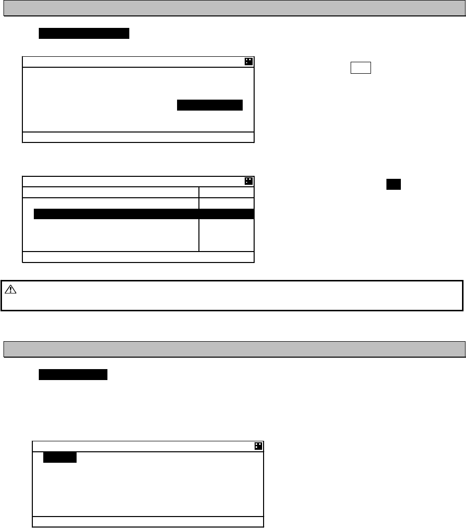
5-56
5.3.4.4 Power Reduction
Select 4. POWER REDUCT, the transmission power can be set.
Select from “NORMAL” and “1W” with key
or key and press ENT to determine.
NORMAL 㨯㨯㨯 transmit by normal power
1W 㨯㨯㨯㨯 the power is changed to 1W
While selecting 1W, there is 1W mark on the
bottom line of screen. (as shown below)
Caution㧦If the transmission power is changed into 1W, the power revert to normal after moving
0.25 NM from the position where the power reduction was made.
5.3.4.5 Registration of Group Ships (GROUP SHIP)
Select 5.GROUP SHIP, GROUP SHIP screen is displayed.
Other ships registered as group ship are displayed as appended “㧖” mark on the left side in LIST
SORT screen and the and the registered ship name.
The number of registration is up to 10.
These registrations can be confirmed with key or key.
5'6 72
'6+/'
/; %10641..'4
4')+10#. %*#00'.
294 4'&7%6014/#.
)4172 5*+2
%*#00'.
219'4 5'6
Ť
.+56 51464#0)'
$4)
c
40)
0/
'6
O
KP 0#/'
5#46
,4%
,4%
61-;
Ť
#+%*
㪈㫎
)4172 5*+2
5*+2 0#/'
//5+
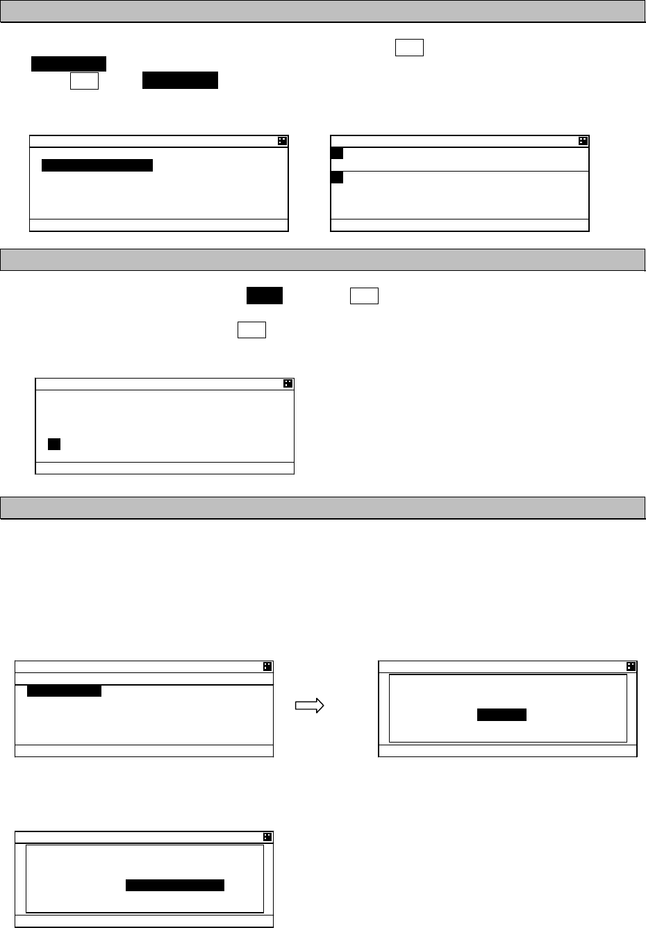
5-57
a) Input name
Select desirable number to change or register and Press ENT key and then the cursor move to
SHIP NAME.
Press ENT key at SHIP NAME, SHIP NAME input screen is displayed.
Refer to “5.2.4 character input method“ to input.
b) MMSI input
After the inputting the name, select MMSI and press ENT key, and then MMSI can be inputted.
MMSI can be inputted one digit at a time. (refer to 5.2.5 Numerical Input)
After inputting the last digit, press ENT key and MMSI setting is finished. The screen move to next
GROUP SHIP screen.
c) Save and Clear
This item is as follows
SAVE 㨯㨯㨯㨯㨯㨯㨯㨯㨯㨯 Save the input after editing
CLEAR 㨯㨯㨯㨯㨯㨯㨯㨯㨯 Erase the register which is selected or edited and switch to GROUP SHIP screen
ALL CLEAR 㨯㨯㨯㨯㨯 Erase all registrations and switch to GROUP SHIP screen
EXIT 㨯㨯㨯㨯㨯㨯㨯㨯㨯㨯㨯 Return to SET UP menu
If [CLEAR] or [ALL CLEAR] are selected, Popup screen is appeared. (as shown below)
If [OK] is selected, the registration is deleted.
If [CANCEL] is selected, switch to previous screen.
5GNGEV=5#8'?
)4172 5*+2
5*+2 0#/'
//5+
5*+2 0#/'
#$%&'()*+,-./01234567
89:;<
=
᳖
?
A
!
"
@
=
%
?
=
#%
?
=
1-
?
=
':+6
?
)4172 5*+2
5*+2 0#/'
//5+
)4172 5*+2
57$ /'07
=
5#8'
?
=
%.'#4
?
=
#.. %.'#4
?
=
':+6
?
)4172 5*+2
5#8' 1-
=
1-
?
)4172 5*+2
#4' ;17 574'
!
=
1-
?
=
%#0%'.
?
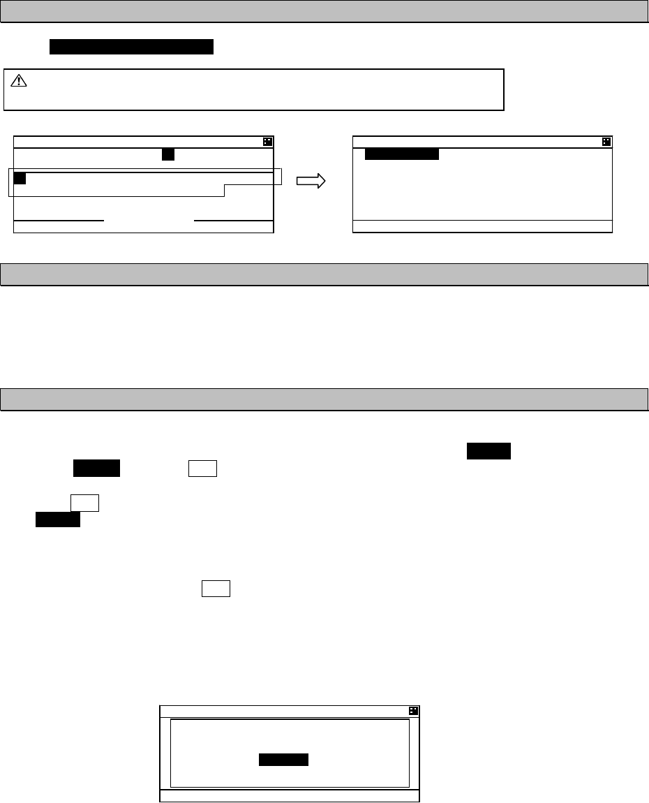
5-58
5.3.4.6 Change of Channels and Transmission Power (CHANNEL/POWER)
Select 6.CHANNEL/POWER SET and enter password, Channels and power can be changed.
Caution㧦Normally, AIS is operated by regulated channels.
Ship’s administrators must be responsible for any change.
a) Password input
Password is composed of alphabet “A㨪Z” and numeric “0㨪9”.
After the 4 digits are input, then the cursor moves to [ENT].
If [ENT] is selected, Channels and power changing screen is displayed. If [EXIT] is selected, switch to
SET UP screen.
b) Channels and power change
Set the channel number and select transmission power
After channel and power changing screen is displayed, the cursor is on 1.CH A.
Select 1. CH A and press ENT key. The cursor move to on the left side of channel number.
Refer to 5.2.5 character input method to input.
Press ENT key on the right side of the channel number, the cursor moves to next item.
(2.CH B takes same procedure.)
Transmission power is selected as shown below.
HIGH㨯㨯㨯㨯㨯㨯㨯normal power
LOW㨯㨯㨯㨯㨯㨯㨯1W
Select the power and press ENT key. The cursor moves to [SET].
If [SET] is selected, AIS starts operation by the setting.
If [EXIT] is selected, switch to SET UP screen.
If invalid channels are inputted or it can not be set, error popup screen (same as “5.3.4.3 Regional
channel setting”) is appeared.
x The transmission power set here is not the same as that of “5.3.4.4 POWER REDUCTION” and the
AIS will continue operation by the set power and is not dependent on the distance moved.
x The setting changed in this menu is reverted to default by restarting the equipment.
%*#00'.
219'4
2#55914&
#$%&'()*+,-./01234567
89:;<
=
᳖
?
A
!
"
@
=
'06
?
=
':+6
?
Input field
%*#00'.
219'4
%* #
%* $
219'4*+)*
=
5'6
?
=
':+6
?
%*#00'.
219'4
%*#00'. '4414
=
1-
?
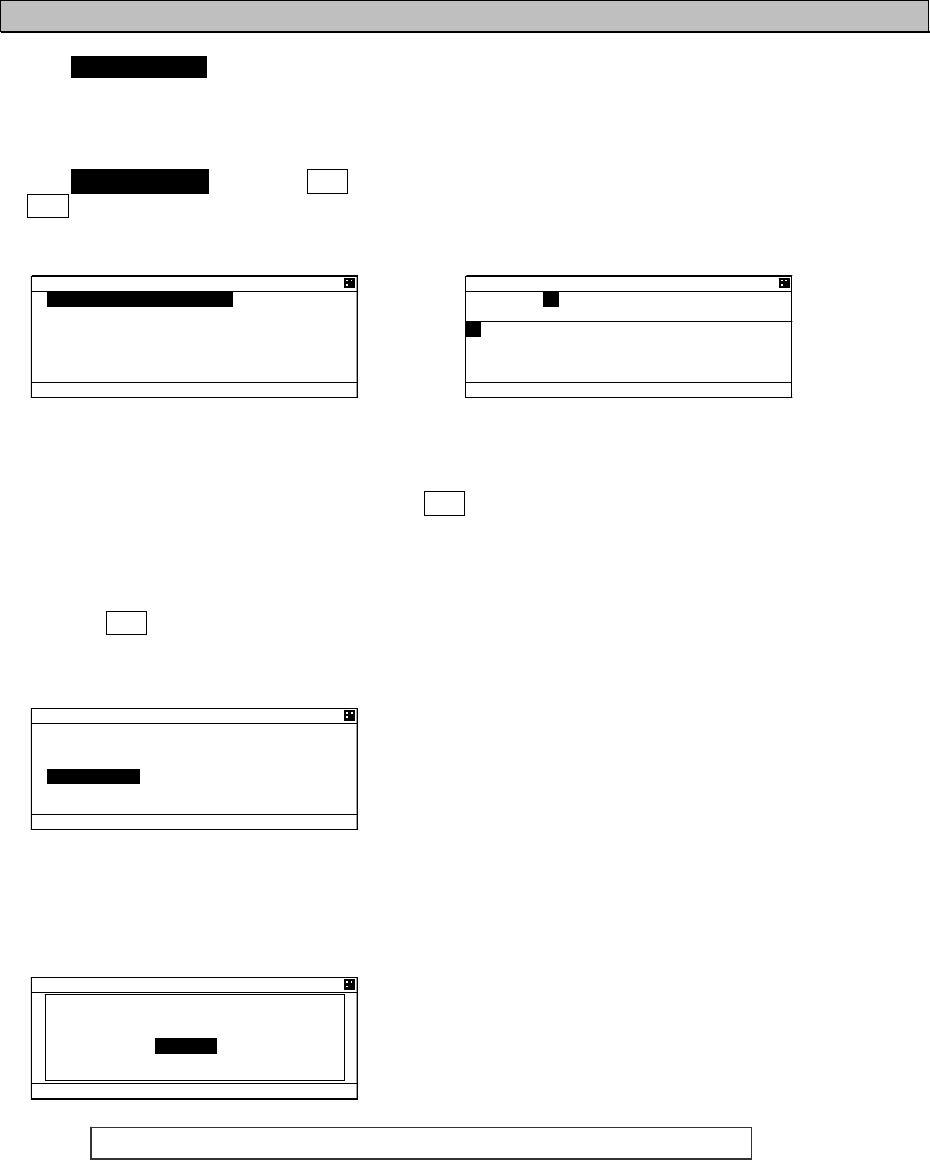
5-59
5.3.4.7 Change Password (PASSWORD)
Select 7. PASSWORD, Password screen is displayed.
In this menu, set the password that is used in case power off or channel change.
The password is managed by ship’s administrator.
Select 1.USER LEVEL and press ENT key.
If CLR is selected, the display is switched to SET UP menu screen.
1. The cursor is on the right side of “OLD” and another cursor is displayed in the character pad at the
same time.
2. Input the current password after “OLD:” by using character pad.
3. After 4 digits input, select [ENT] and press ENT key.
If the password is not matched with current one, the cursor returns to the first digit.
Factory default password is set “0000”.
If the password is matched with current one, the cursor move to first digit of “NEW”.
4. Input the new 4 digits password at ”NEW:”
5. Press ENT key at last digit
If [ENT] is selected, new screen is appeared and the cursor is at [SAVE].
If [EXIT] is selected, discard the input and return to PASSWORD screen.
6. At the above screen
Select [SAVE], new password is saved and display switches to SET UP menu
Select [EXIT] , discards the input and display switches to the PASSWORD screen.
If password setting is not completed, Popup screen (as shown
left) appears.
In this case, Select [SAVE] again or change to another
password.
Note) Password is composed of alphanumeric “A㨪Z” and “0㨪9”.
2#55914&
75'4 .'8'.
75'4 .'8'.
1.&
0'9
#$%&'()*+,-./01234567
89:;<
=
᳖
?
A
!
"
@
=
'06
?
=
':+6
?
75'4 .'8'.
1.&
0'9
=
5#8'
?
=
':+6
?
75'4 .'8'.
4'57.65'6 0)
=
1-
?
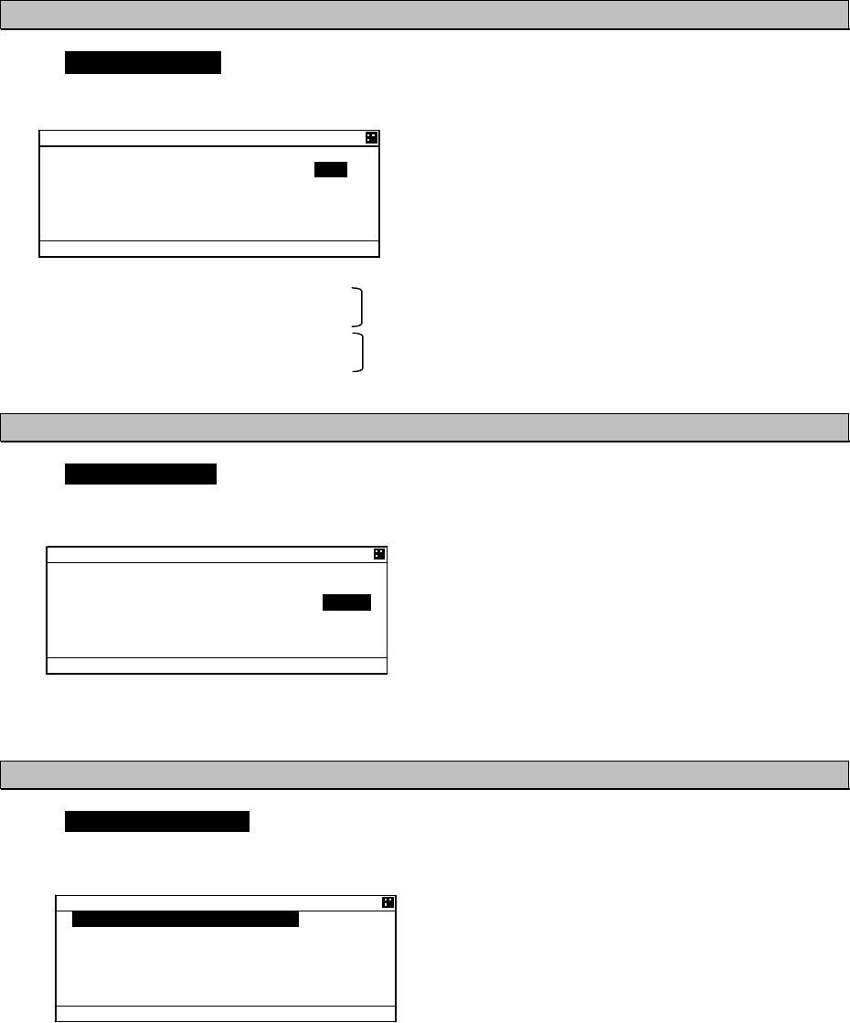
5-60
5.3.4.8 Display Style of Latitude and Longitude (POSN DISP SET)
Select 8. POSN DISP SET, the display style (display position of N/S, E/W㧕can be changed.
SettingOFF㧦 N xx°xx.xxx Positioned in front of coordinate
Wxxx°xx.xxx
ON㧦 xx°xx.xxx’ N Positioned at the back of coordinate
xxx°xx.xxx’ W
5.3.4.9 Indication of AIS SART test signal (SART TEST SET)
Select 9.SART TEST SET, The test of AIS SART can be set.
Select the operation whether AIS displays the signal at LIST SORT screen or GRAPHIC screen after
receiving the SART test signal or not.
Select the operation
OFF 㨯㨯㨯 Displays only main signal of AIS SART
ON 㨯㨯㨯㨯 Displays both test signal and main signal.
When the test signal is received, AIS displays “SART TEST” at LIST SORT screen.
When the main signal is received, AIS displays “SART ACTIVE”.
5.3.4.10 Long-Range Set
Select 10.LONG-RANGE SET, Long range setting screen is displayed.
In this menu, Each item concerned with long range can be set
.
1. LR BROADCAST㨯㨯㨯Select the use of long range broadcast
2. CH A 㨯㨯㨯㨯㨯㨯㨯㨯㨯㨯Set the channel for CH A transmission
3. CH B 㨯㨯㨯㨯㨯㨯㨯㨯㨯㨯Set the channel for CH B transmission
4. LONG-RANGE㨯㨯㨯㨯㨯㨯Select the response type from AUTO or MANUAL.
5'6 72
2#559#4&
2150 &+525'610
5#46 6'56 5'61((
.10)4#0) 5'6
5+.'06 /1&'1((
%%42 5'61((
Ť
5'6 72
2#559#4&
2150 &+525'610
5#46 6'56 5'61((
.10)4#0) 5'6
5+.'06 /1&'1((
%%42 5'61((
Ť
.10)4#0)'
.4 $41#&%#561((
%* #
%* $
.10)4#0)'#761
=
5'6
?
=
':+6
?
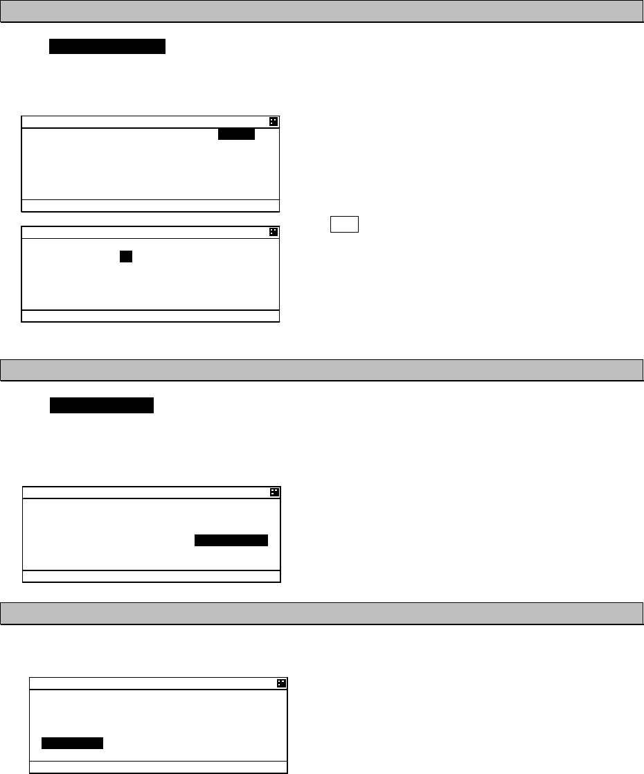
5-61
a) Setting of long range management
Select 1.LR BROADCAST, Long range broadcast can be set.
AIS transmits own ship’s position or navigation status by long range broadcasting (using satellite etc.)
The channels are specified in item 2.3.
The AIS will respond, in cases where a coast radio station requests own ship's information.
Select from ON or OFF with key or key.
ON 㨯㨯㨯㨯㨯㨯㨯㨯 Transmit the response by the setting
channel (set at item 2.3) .
OFF 㨯㨯㨯㨯㨯㨯㨯 Not transmit the response.
But requested by LR port,
Output the response through LR port.
Press ENT key to decide after selection
Set the channel to transmit for long range response.
Input the channel number one digit at a time.
(Refer to “5.2.5 numerical input”)
Factory default settings are 2075ch and 2076ch.
b) Setting of long range response
Select 4.LONG-RANGE, Long range response can be set. Long range transmission operates in cases
where the AIS is connected to equipment that supports long range transmission.
In this menu the response type shown in paragraph 5.3.2.5 "Confirmation of long range message"
refers.
AUTO: Respond automatically
MANUAL: Respond by manual
c) Save the setting
Save the setting of item from 1 to 4.
Select [SET], save the setting and switch to SET UP
menu.
Select [EXIT], discard the setting and switch to the SET
UP menu.
.10)4#0)'
.4 $41#&%#561((
%* #
%* $
.10)4#0)'#761
=
5'6
?
=
':+6
?
Ť
.10)4#0)'
.4 $41#&%#561((
%* #
%* $
.10)4#0)'#761
=
5'6
?
=
':+6
?
.10)4#0)'
.4 $41#&%#561((
%* #
%* $
.10)4#0)'/#07#.
=
5'6
?
=
':+6
?
Ť
.10)4#0)'
.4 $41#&%#561((
%* #
%* $
.10)4#0)'/#07#.
=
5'6
?
=
':+6
?
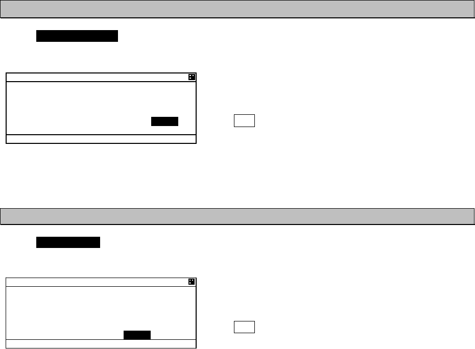
5-62
5.3.4.11 Prohibition of Transmission
㧔
SILENT MODE
㧕
Select 11.SILENT MODE, and Silent mode is available.
This is used for intentional prohibition of transmission.
Select from ON or OFF with key or key.
OFF 㨯㨯㨯 Continue normal operation
ON 㨯㨯㨯㨯 Prohibit from transmitting while selected.
Press ENT key to determine.
When the AIS is prohibited from transmitting, there is always “RX” mark on the bottom line of screen.
5.3.4.12 CCRP Set
Select 12.CCRP SET, The use of CCRP (Consistent Common Reference Point) can be selected.
The AIS will display the distance or compass direction on the basis of the CCRP setting.
Select from ON or OFF with key or key.
OFF 㨯㨯㨯 Set AIS controller’s position as the reference
point
ON 㨯㨯㨯㨯 Set CCRP for t as the reference point
Press ENT key to determine.
5'6 72
Ţ
2#559#4&
2150 &+525'610
5#46 6'56 5'61((
.10)4#0) 5'6
5+.'06 /1&'1((
%%42 5'61((
Ť
5'6 72
Ţ
2#559#4&
2150 &+525'610
5#46 6'56 5'61((
.10)4#0) 5'6
5+.'06 /1&'1((
%%42 5'61((
Ť
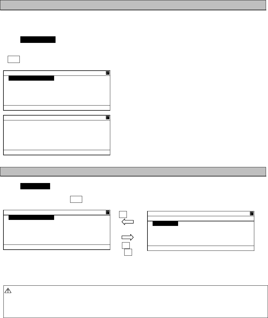
5-63
5.3.4.13 Initial Setting of Own Ship’s Heading Direction
㧔
NSK UNIT
㧕
When the NSK unit (gyro interface option) is installed, then the heading direction needs to be set.
This item is displayed when AIS is connected with NSK unit and its setting is available.
Select 10. NSK UNIT, Own ship’s heading and the setting of NSK UNIT are displayed.
If CLR key is selected, the display will switch to the SET UP menu.
In this menu, Item 1.HEADING value can only be set.
Other items (from 2 to 8) show current NSK unit’s setting
and alarm information.
a) Initial value input of heading
Select 1.HEADING, Heading value can be set.
The value is between 000.0° to 359.9° and input one digit at a time by using UP/DOWN key.
After all digits input, Press SUB key and then SUB menu is appeared.
In this SUB menu
Select [SET], saves the heading value and switches the display to SET UP menu.
Select [EXIT], Discards the input and switches the display to the NSK UNIT menu.
Caution: In case some alarm occurred at NSK unit and NSK is recovered, this screen is displayed
and setting the heading value is necessary.
If the display is switched to another screen without the NSK being set, the AIS will request the
heading input on a regular basis. Therefore this screen is displayed again.
57$MG[
%.4MG[
57$MG[
05- 70+6
*'#&+0)
c
#.#4/241)/'9'44
6;2'56'2
4#6+1:
&+4'%6+10014/
Ť
05- 70+6
Ţ
176276 6+/+0)
/5
5+/7.#614
'44 6+/+0)5
05- 70+6
57$ /'07
=
5'6
?
=
':+6
?
05- 70+6
*'#&+0)
c
#.#4/241)/'9'44
6;2'56'2
4#6+1:
&+4'%6+10014/
Ť

5-64
b) Details of NSK Unit setting
Each item’s detail are shown below
2. ALARM
Current alarm of NSK UNIT
Indication Description
OK Normal
SYNCIRQ ERR
SYNCWIRE ERR
Connection error in case sync type selected
㧔e.g. breaking of wire㧕
STEPIRQ ERR
STEPWIRE ERR
Connection error in case step type selected
㧔e.g. breaking of wire㧕
PROG.MEM.ERR Operation error
3. TYPE
Displays the type of gyrocompass
Indication Description
STEP Step signal
SYNC Sync signal
4. RATIO
Displays the rotation ratio
Indication Description
36X
90X
180X
360X
Rotation ratio
5. DIRECTION
Displays the direction of rotation
Indication Description
REV Reversal㧔a left-handed rotation㧕
NORM Normal㧔a right-handed rotation㧕
6. OUTPUT TIMING
Displays the renewal time of heading value
Indication Description
RESERV Reserved
1S Renew the heading every 1 second
100MS Renew the heading every 0.1 seconds
50MS Renew the heading every 0.05 seconds
7. SIMULATOR
Displays the operation mode
Indication Description
TEST Operation check mode.
The heading value shows 0.0 always.
NORM Normal operation mode㧔displayed normally㧕
8. ERR TIMING
Displays the alarm detecting time
Indication Description
5S Detect the alarm every 5 seconds
0.2S Detect the alarm every 0.2 seconds