Japan Radio JHS-183 MARINE AIS CLASS A User Manual E a
Japan Radio Co Ltd. MARINE AIS CLASS A E a
Contents
- 1. User Manual 2
- 2. User Manual 1
User Manual 2
5-65
5.4 Explanation of Graphic display
5.4.1 The Outline of Display
NCM-983 Panel side and Display
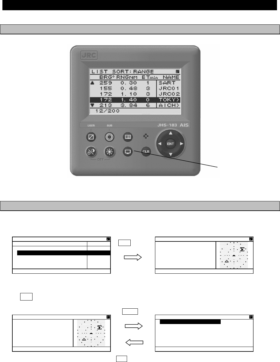
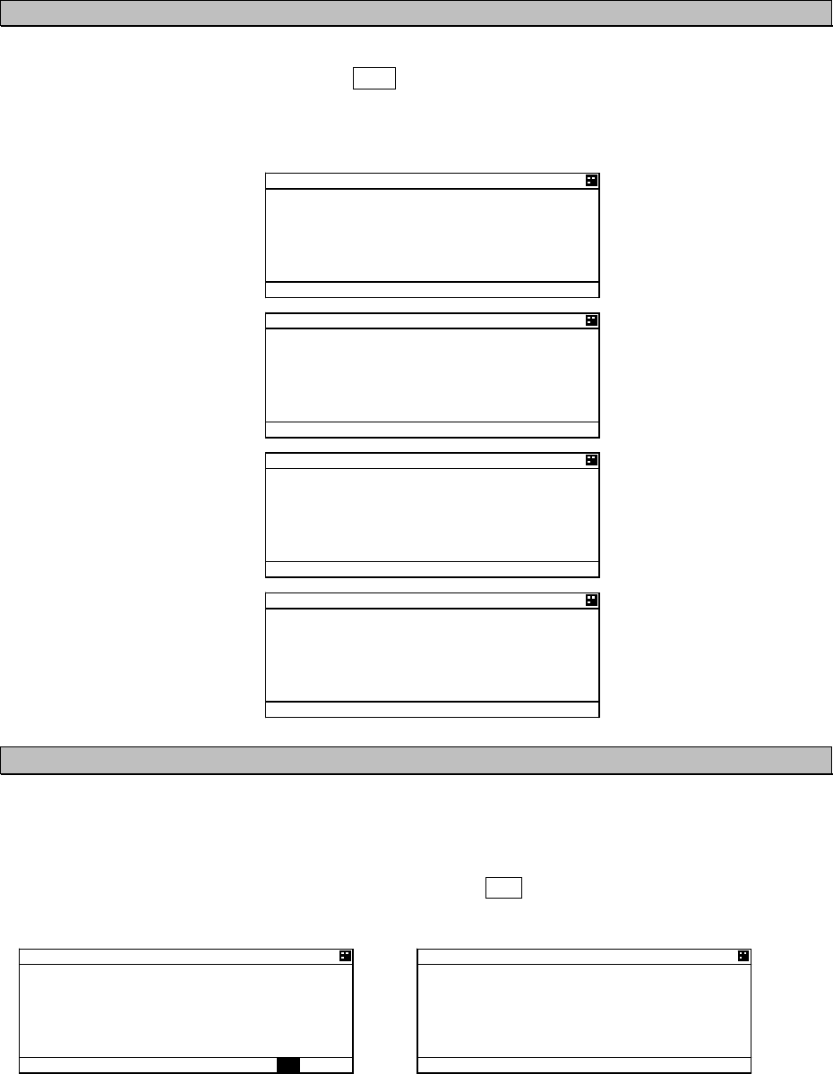
5.4.2 Operation for Graphic display
In order to switch the display, press DISP key until Graphic display is appeared.
Also, the display can be switched from Graphic display to MAIN MENU to change the setting of this
equipment.
Press CLR key at MAIN MENU, the display is switched to Graphic display.
DISP key
DISP key
MENU key
CLR key
.+56 51464#0)'
$4)
c
40)
0/
'6
O
KP 0#/'
5#46
,4%
,4%
61-;
Ť
#+%*
/#+0 /'07
81;#)' #
/'55#)'
/#+06'0#0%'
5'6 72
=
':+6
?
)4#2* 40) 0 72
,4%
$4)
c
40) 0/
*&)
c
51) MP
%1)
c
)4#2* 40) 0 72
,4%
$4)
c
40) 0/
*&)
c
51) MP
%1)
c
5-66
5.4.3 Setting the Contents of Graphic Display
Explain the setting of graphic display (e.g. range changes, setting of guard zone).
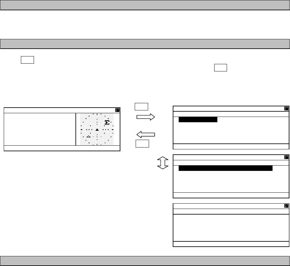
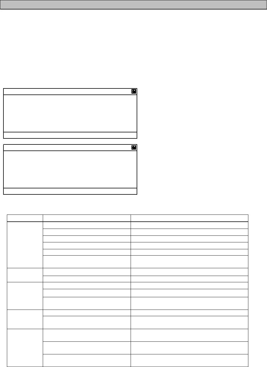
5.4.3.1 Display the Setting Screen
Press SUB key at Graphic screen, and then switch to SUB MENU.
In this SUB MENU, Select the desirable item with key or key and Press ENT key, then the item
can be set.
When [SET] is selected on page 2/3, the setting is saved.
When [EXIT] is selected on page 3/3, the display switched to MAIN MENU.
5.4.3.2 Display Item Explanation
1. RANGE
RANGE means the radius of external circle in the graphic screen.
It is selected from 6 steps (0.75,1.5,3,6,12,24NM㧕with key or key.
2. BEARING
North up of Head up can be select with key or key.
North up 㧦Displays on a north basis
Head up 㧦Displays on own ship’s heading basis.
In case Heading value is not inputted (Not available), Only North up can be selected.
3. SORT
SORT is selected from RANGE, TCPA and GROUP with key or key.
RANGE 㧦In order of the distance from own ships and OTHER SHIPS LIST is arranged.
TCPA 㧦In order of small TCPA from own ship and the list is arranged.
GROUP 㧦In order of the distance and gives priority GROUP SHIP, and the list is arranged.
SUB key
SUB key
or
)4#2*+% &+52 5'6
57$ /'07
4#0)'0/
$'#4+0)0146* 72
51464#0)'
0#/'5*+20#/'
Ť
)7#4& <10'0/
)4#2*+% &+52 5'6
57$ /'07
Ţ
07/$'4 1( 5*+25
%1064#56
#761 4#0)'10
Ť
=
5'6
?
)4#2*+% &+52 5'6
57$ /'07
Ţ
=
':+6
?
)4#2* 40) 0 72
,4%
$4)
c
40) 0/
*&)
c
51) MP
%1)
c
5-67
4. SHIP NAME
The SHIP NAME is selected from SHIP NAME and MMSI.
5. GUARD ZONE
The range of GUARD ZONE ALARM can be set. The range is set from 0 to 99.9NM.
If 00.0NM is set, the alarm is cancelled.
㧔In order to see this operation, refer to 5.2.3.1 GUARD ZONE ALARM㧕
6. The number of ships displayed in Graphic screen
The number of ships displayed in Graphic screen can be limited.
The number is selected from 8,16,24,32,200 with key or key.
This function is set in case it is hard to distinguish others in this screen.
7. CONTRAST
The contrast of display can be adjusted.
The range is selected from 1 to 13 with key or key.
8. AUTO RANGE
When a ship (located within 24NM) is selected in the list, Graphic range is set automatically and
is adjusted to its distance.
Select from ON (valid) or OFF (invalid) with key or key.
5-68
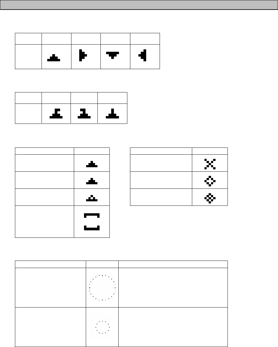
5.4.3.3 Display
Ԙ
Heading
㧦
In 90-degree segment, 4 types are listed below.
Value
[degree]
314.5㧙
45.4
45.5㧙
134.4
134.5㧙
224.4
224.5㧙
314.4
Display
䂾
䂾
䂾
䂾
ԙ
ROT
㧦
3 types are listed below.
Course +
(right)
㧙
(left)
0
(straight)
display
䂾
䂾
䂾
Ԛ
Other marks
Classification Mark Classification Mark
Own ship
䂾
AIS SART
䂾
Other ships
䂾
Mark of route(Real)
Aids to navigation
䂾
Base station
䂾
Mark of route
(Virtual)
䂾
Cursor
ԛ
Display line
Classification Mark Note
Range circle
Setting range
Displayed by 15 degree interval circle.
Guard zone alarm circle
Setting range of guard zone
Displayed by 30 degree interval circle
5-69
5.4.4 Selection of Other Ships
The cursor in Graphic display can move with key or key.
When key is pressed, ships are selected by descending order of the setting SORT.
When key is pressed, ships are selected by ascending order of the setting SORT.
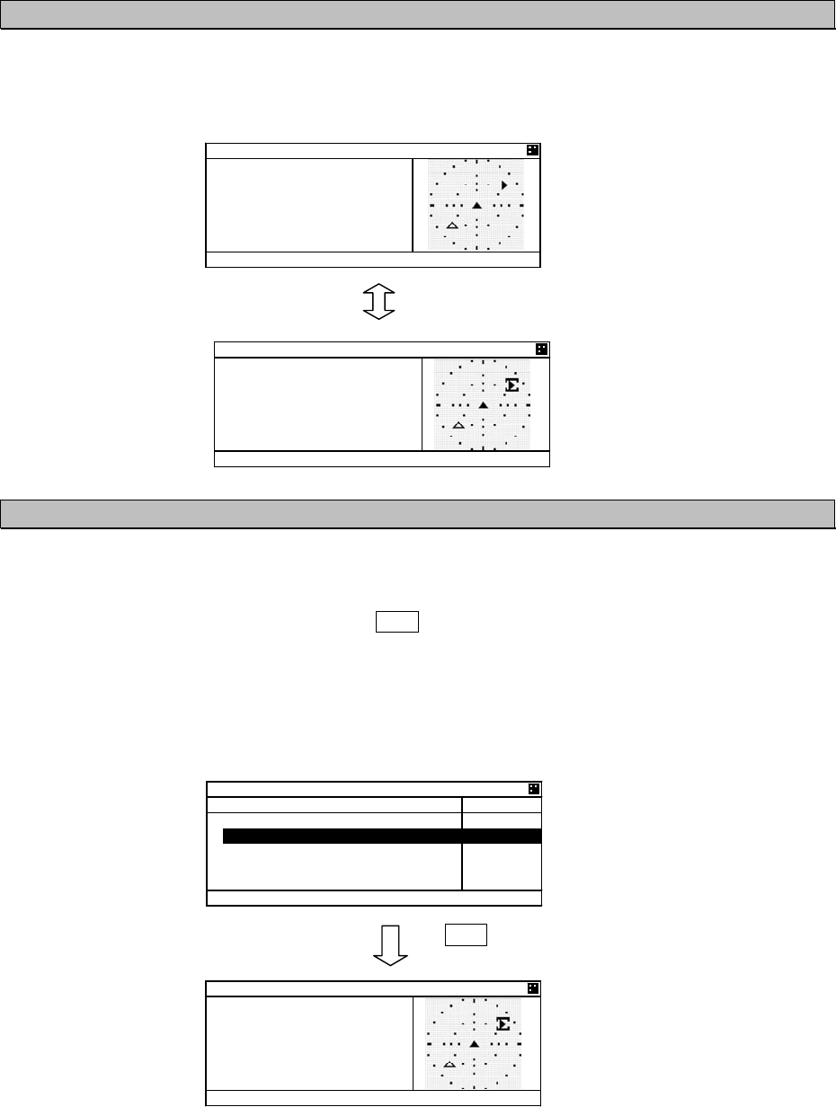
5.4.5 Auto Range Setting
After “AUTO RANGE” is set “ON” (valid), this function works under the condition shown below.
On condition that Graphic range set previously is smaller than the ship’s distance selected in the
list (located within 24NM), and then press DISP key and displays the Graphic screen.
The range is set automatically and is adjusted to its distance. Therefore the ship selected can be
confirmed in the Graphic display.
e.g.㧕If the Graphic range is set 0.75NM previously and A ship which is 4.85NM away from own ship is
selected in the list, the progress is shown below.
The range is changed 0.75NM into 6.0NM.
DISP key
or
.+56 51464#0)'
$4)
c
40)
0/
'6
O
KP 0#/'
0+*10
,4%
$#5'
)4#2* 40) 0 72
,4% /#47
*&)
c
51) MP
%1)
c
)4#2* 40) 0 72
,4%
$4)
c
40) 0/
*&)
c
51) MP
%1)
c
)4#2* 40) 0 72
,4%
$4)
c
40) 0/
*&)
c
51) MP
%1)
c
5-70
6-1
6. MAINTENANCE AND INSPECTION
The performance and longevity of this equipment depend on careful maintenance. To maintain the best
performance, the following periodic inspections are highly recommended.
(1) Keep the power supply voltage within the specified value (19-35Vdc).
(2) Know the condition of normal status when the equipment is properly functioning. Keep comparing
the current status to the normal status to immediately detect any malfunctions.
Do not attempt to check or repair the interior of this equipment by non-qualified
service personnel, as doing so may cause fire, electric shock or malfunction. If
any malfunctions are detected, contact our service center or agents.
6. 1 General Maintenance and Inspection
Below are listed general maintaining and inspecting items, which can be done with usual tools and
apparatus.
No. Item Maintenance and inspection
1 Cleaning
Gently clean the surface of the panel, knobs, switches, and cover with soft
cloth or silicon oil. No oil is needed because this unit has no moving
mechanisms inside.
2 Looseness
of parts
Inspect for looseness and correctly tighten the following:
Screws, nuts, knobs, switches and connectors.
3 Fuse
When checking and replacing the fuse, be sure the power is off.
If the power source fuse is blown, be sure to inspect the cause before
replacing the blown fuse with a new one.
4 Unit
Check whether there is discoloration of parts mounted to the unit.
When exchanging a unit, contact our service center or agents.
WARNING

6-2
6.2 Periodic Inspection
6.2.1 Confirming the Own Ship’s Information
Displays own ship’s detail information and confirm that the static (ship name, MMSI etc.) and dynamic
(position, heading etc.) information is correct.
In order to display the Own Ship’s Detail Information, Press DISP key several times and the screens
are changed by each key press. Own Ship’s Detail Information is composed of 2 screens.
Own ship’s detail1 information
(
Static information
)
Own ship’s detail2 information
(
D
y
namic information
)
190 5*+2
5 &'6#+.
//5+
0#/'
,4% /#47
+/1 01
%#.. 5+)0
Ť
190 5*+2
5 &'6#+.
//5+
0#/'
,4% /#47
+/1 01
%#.. 5+)0
Ť
190 5*+2
5 &'6#+.
Ţ#06 2150 ':6 +06
$19 O O
564 O O
214 O O
56# O O
Ť
190 5*+2
5 &'6#+.
Ţ2150 &'8+%'
)25
0#8 56#675
'0)#)'& +0 (+5*+0)
Ť
190 5*+2
5 &'6#+.
Ţ&'56+0#6+10
,#2#0
'6#
/
&*/
&'%
Ť
190 5*+2
5 &'6#+.
Ţ&4#7)*6
O
2'45105 14 /14'
6;2' 1( 5*+2
2#55'0)'4 5*+25
Ť
190 5*+2
5 &'6#+.
Ţ%#4)1
56#675
#.. 5*+25 1( 6*+5 6
;2'
190 5*+2
5 &'6#+.
2150 &'8+%'
)25
.#6
c
0
.10
c
'
51) MP
Ť%1)
c
190 5*+2
5 &'6#+.
2150 &'8+%'
)25
.#6
c
0
.10
c
'
51) MP
Ť
%1)
c
190 5*+2
5 &'6#+.
Ţ
*&)
c
416
c
OKP
2150 37#.+6;
2150 /
2#.19 4#+/01 75'
Ť
6+/' 56#/2
190 5*+2
5 &'6#+.
Ţ
#%% (41/ 4#+/
01 4#+/ 241%'55 #8#
+.#$.'
Ť
190 5*+2
5 &'6#+.
Ţ
5;0% 56#6'
76% &+4'%6
4%8 56#6+105
Ť
6-3
6.2.2 Confirming the TRX Channel
Display the TRX (transponder) condition and confirm that the TRX Channel information is correct.
In order to display “Own ship’s TRX”, Press DISP key at “Own ship’s detail 2” screen.
In case international frequencies are used, the information is displayed as below.
6.2.3 Confirming the Alarm Status
Display the AIS alarm status and confirm there is no alarm. In order to display the AIS alarm status,
Select “Main Menu” “3. MAINTENANCE” “3. AIS ALARM”.
Built-in integrity test (BIIT) is always working during AIS equipment operation to watch over any alarms
and there is a visual and audible signal when it detects any alarms when it detect any alarm. After the
automatic displayed alarm screen is closed by pressing CLR key, the current AIS alarm can be
confirmed with the AIS alarm status screen.
The present alarm occurrence status The status when there is no alarm.
If any alarms occur, confirm the alarm occurrence conditions with the alarm table.
#+5 #.#4/
01 #
190 5*+2
564:
%* #
%*$
6: 219'4 *+)*
/1&'
#$
%* # 6:
4:
Ť
%* $ 6:
4:
190 5*+2
564:
Ţ
#4'#
0'
016 #8#+.#$.'
016 #8#+.#$.'
#4'#
59
016 #8#+.#$.'
Ť
016 #8#+.#$.'
190 5*+2
564:
Ţ
5174%'
$#5' 560 //5+
76%
Ť
190 5*+2
564:
Ţ
<10' 5+<' 0/
#+5 #.#4/
#8 ':6'40#. '2
(5 .156
㪘㪣

6-4
JHS-183 Alarm Table
Failure alarm (ALR sentence output)
Alarm No. Indication Alarm Occurrence Conditions
003 Rx channel 1 malfunction The RX CH A synthesizer is unlocked.
004 Rx channel 2 malfunction The RX CH B synthesizer is unlocked.
005 Rx channel 70 malfunction The RX CH70 synthesizer is unlocked.
008 MKD connection lost Communication between the transponder and
controller is failed. (Transponder generates the
alarm.) AIS Transponder setting is initialized.
064 mkd connection lost Communication between the transponder and
controller is failed. (Controller generates the
alarm.)
010 Nav Status incorrect There is a difference between the setting of Nav
status and actual Nav status.
-Nav status is set from “at anchor”, “moored”
and “aground”, and “SOG” is over 3kn.
-Nav status is set "UNDER WAY SAILING" or
“UNDER WAY USING ENGINE”, and SOG is
under 1kn.
014 Active AIS SART AIS SART SIGNAL is received.
025 external EPFS lost Any one of the following commands has not been
entered from the external sensor or data is invalid.
GNS, GLL, GGA, RMC
026 no sensor position in use The internal GPS is invalid and the following
commands has not been entered from the
external sensor or data is invalid.
GNS, GLL, GGA, RMC
029 no valid SOG information The internal GPS is invalid and the following
commands has not been entered from the
external sensor or data is invalid.
VBW, VTG, OSD, RMC
030 no valid COG information The internal GPS is invalid and the following
commands has not been entered from the
external sensor or data is invalid.
RMC, VTG, OSD
032 Heading lost/invalid Any of the following commands has not been
entered from the external sensor or data is invalid.
HDT, OSD, THS
035 no valid ROT information Any of the following commands has not been
entered from the external sensor or data is invalid.
HDT, OSD, THS, ROT
056 Tx power too low Tx power level is too low.
058 Tx stop interrupt Transmission was stopped forcibly.
059 Tx power too high Tx power level is too high.
061 Not Tx No transmission
062 Program flash memory error The flash memory for programs is abnormal.
063 Data flash memory error The flash memory data is abnormal.
006
052
general failure
Tx power supply error
The voltage became abnormal during
transmission because of PA failure.
006
053
general failure
Power supply error
The voltage became abnormal during reception
because of PA failure.
001
054
Tx malfunction
Pa current error
The PA collector current became abnormal during
transmission.
001
055
Tx malfunction
Pa temp error
The PA temperature became abnormal during
transmission.
002
051
Antenna VSWR exceeds
limit
Computed result of VSWR is 3 or greater but no
greater than 4 during rated transmission output or

6-5
Tx power down transmission level is lowered.
001
002
Tx malfunction
Antenna VSWR exceeds
limit
The computed result of VSWR is 4 or greater.
001
057
Tx malfunction
Vr error
The antenna is open or broken.
001
060
Tx malfunction
Tx pll unlock
The TX synthesizer is unlocked.
6-6
6.2.4 Confirming the Conditions of the Sensors
Display the sensor status and be sure that the sensor is working.
To display the sensor status, please select “Main Menu” “3. MAINTENANCE” “4. SENSOR
STATUS”.
POSITION: Be sure that the indicated status is not NO SENSOR.
UTC CLOCK: Be sure that the indicated status is IN USE. (It takes some time before IN USE
appears in case the power has been off for a long time.)
SOG/COG: Be sure that the indicated status is not NO SENSOR.
HEADING: Be sure that the indicated status is not INVALID.
ROT: Be sure that the indicated status is not NO SENSOR.
5'0514 56#675
215+6+10
':6'40#. )055
76% %.1%-+075'
51)
%1)':6'40#.
*'#&+0)8#.+&
Ť
416+075'
5'0514 56#675
Ţ
+& %1//#0&
2150)2 4/%
51) )2 4/%
%1) )2 4/%
*&) *' *&6
416 6+ 416
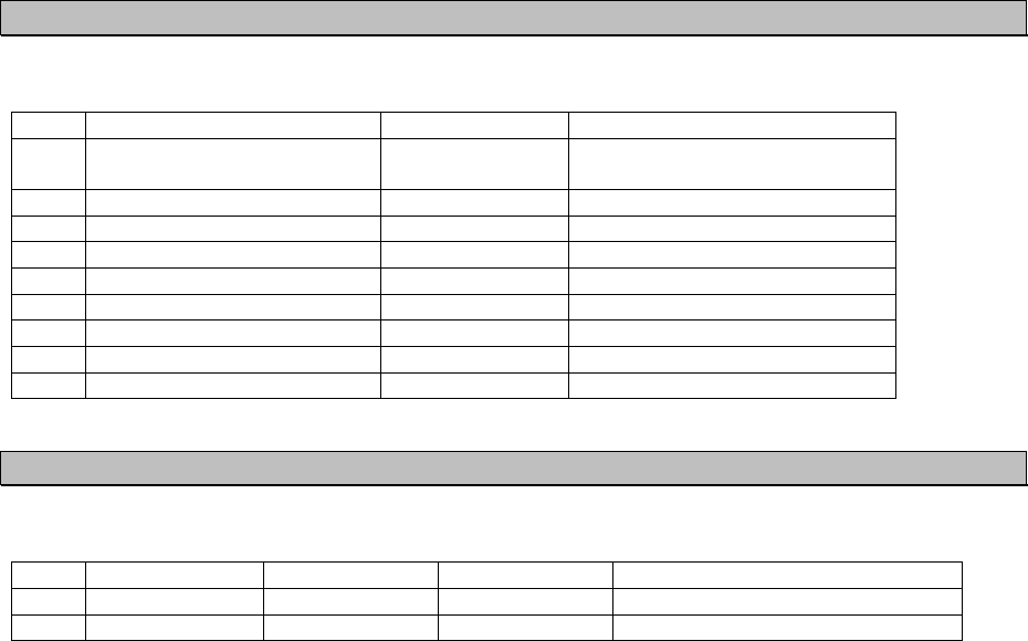
The variation of the sensors’ conditions is tabulated below.
Sensor Indication Sensor’s Condition
EXTERNAL DGNSS The external DGNSS is in use.
EXTERNAL GNSS The external GNSS is in use.
INT DGNSS (BEACON) The internal DGNSS (beacon) is in use.
INT DGNSS (MSG.17) The internal DGNSS (message 17) is in use.
INTERNAL GNSS The internal GNSS is in use.
POSITION
NO SENSOR The position data is not yet entered or invalid
or not received.
IN USE The internal GPS compensates PPS. UTC
CLOCK LOST The internal GPS has not compensated PPS.
EXTERNAL The external SOG/COG is in use
INTERNAL The internal SOG/COG is in use
SOG
/COG
NO SENSOR The SOG/COG data are not yet entered or
invalid or not received.
VALID Heading data are entered. HEADING
INVALID Heading data are not yet entered or invalid or
not received.
IN USE The ROT data input from a rate-of-turn
indicator.
OTHER SOURCE The ROT data input from a source other than
a rate-of turn indicator.
ROT
NO SENSOR The ROT data are not yet entered or invalid or
heading data not received.
6-7
6.3 Trouble Shootings
6.3.1 Trouble Shootings
For reference, this section presents a troubleshooting guideline for finding defective sections.
Symptom of Error Possible Cause or Cause of Fault Countermeasures
Power is not distributed from the
inboard distribution panel.
Supply power from the distribution
panel.
Power is not supplied from the
power supply unit (NBD-577C).
Check that the wiring of the power
unit is correct.
Check that the output voltage of the
power unit is correct.
The supply voltage of power supply
(NBD-577C) is out of range.
Replace the power unit.
The fuses in the connection box are
blown out.
Check that the wiring is correct and
replace the fuses.
The termination in the connection
box is broken.
Replace the NQE-5183 connection
box.
Power is not supplied to the
connection box.
Check the wiring and confirm that
the connection is correct
The IC in the AIS controller is
broken.
Replace the CQD-2983 circuit
board.
The power supply cable of the
transponder is broken.
Replace the power supply cable of
the transponder.
The power module in the controller
is broken.
Replace the CBD-2983 circuit
board.
Power is not supplied
when the power switch
is pressed
The key switch is broken. Replace the switch panel
(CDJ-2983) .
The transponder power is not
turned on.
Check the voltage at the end of
transponder cable.
The transponder
software version is -.--.
The transponder is not turned on.
The IC which supplies a power in
the transponder is broken.
Replace the transponder.
The panel unit malfunctions. Replace the CDJ-2983 circuit
board.
No response after
pressing a key on the
operation panel. The DPU malfunctions. Replace the CDJ-2983 circuit
board.
The LCD malfunctions. Replace the LCD unit. Some dots are missing
on the LCD. The control unit malfunctions. Replace the CDJ-2983 circuit
board.
BUZZER has been set “OFF” Set BUZZER to “ON”
(MENU 4.2.2 BUZZER)
The buzzer malfunctions.
No alarming sound is
generated.
The control unit malfunctions.
Replace the CDJ-2983 circuit
board.
Do not attempt to check or repair the interior of this equipment by non-qualified
service personnel, as doing so may cause fire, electric shock or malfunction. If
any malfunctions are detected, contact our service center or agents.
WARNING

6-8
Symptom of Error Possible Cause or Cause of Fault Countermeasures
The control unit malfunctions. Replace the CDJ-2983 circuit
board.
The illumination does
not light.
The LCD malfunctions. Replace the LCD unit.
The transponder is not turned on. Confirm whether the transponder is
turned on.
(MENU 3.1.1 TRANSPONDER)
The whip antenna is damaged. Replace the whip antenna.
The following alarm number
appears: 003, 004, or 005.
The synthesizer in the receiving
circuit is unlocked.
Replace the transponder.
No AIS message is
received.
Channel setting is not correct. Set it by operating channels.
(MENU 4.6 CHANNEL/POWER)
The following alarm number
appears.
001, 052, 53: Power circuit fault
001, 054: PA collector current
abnormal
001, 055: PA temperature abnormal
001, 058: PA protection circuit
operated
001, 060: TX synthesizer unlock
operated
003, 004, 005: RX synthesizer
unlock operated
Replace the transponder.
001, 057: Antenna not connected Check that the antenna is
connected.
Check the setting of antenna
selection from external and internal.
001, 002: VSWR abnormal Check that the antenna is
connected.
Check that there are no objects
around the antenna.
Replace the antenna and check for
normal transmission.
No AIS message is
transmitted.
MMSI has been set “000000000” Set the MMSI correctly.
The cable is not connected
properly.
Check the connection.
The polarity of the serial cable is
incorrect.
Check the polarity and connect it.
The interface between the sensor
and connection box is incorrect.
Check the interface before its
connection.
The sentence that the sensor
generates is not supported by the
AIS.
Check the output command and the
version.
(Refer to 8.3.4 Supported Interface
Sentence)
The sentence that the sensor
generates does not match the
sentence setting of the controller.
Check the output sentence and
sensor setting of JHS-183.
The sensor data flag has been set
to “invalid”.
Check if the sensor is working
correctly.
The sensor (GPS, gyro, rate-of-turn
indicator) malfunctions.
Replace the sensor.
Sensor data (external
GPS, gyro, and
rate-of-turn) cannot be
loaded.
The control unit malfunctions. Replace the CDJ-2983 circuit
board.

6-9
Symptom of Error Possible Cause or Cause of Fault Countermeasures
Internal GPS data
cannot be loaded.
Internal GPS malfunction Execute TEST2 of self-diagnosis.
If the result is “NG”, replace the
transponder.
External GPS data is abnormal. Confirm the external GPS setting.
If there is any failure, replace the
external GPS.
There is a difference
between internal GPS
data and external GPS
data. Internal GPS data is abnormal. Replace the transponder.
External senor data is abnormal. Confirm the external sensor setting.
If there is any failure, replace the
external sensor.
Heading data is
mismatched.
The value of NSK unit is abnormal. Re-set the initial value of NSK unit.
If the setting is not available, check
the dip switch setting.
In case of another, replace the NSK
unit.
There is a difference
between Nav status
and actual Nav status.
Nav status is set by “at anchor”,
“moored” or ”aground”. And SOG is
over 3kn. The condition that Nav
status is set by “under way sailing”.
And SOG is under 1kn is continued
for 2 hours or more.
Change the Nav status to another.
6-10
6.3.2 Maintenance Units
Maintenance units for repair are followings.
No. Unit Name Model Note
1 AIS Transponder NTE-183-2 Transponder
(CAV-2180 is unattached.)
2 VHF Antenna CAV-2180 Whip antenna
3 IFU CQD-2983 Circuit board for NCM-983
4 PSU CBD-2983 Circuit board for NCM-983
5 DPU CDJ-2983 Circuit board for NCM-983
6 CONNECTION BOX NQE-5183
7 NSK UNIT NSK UNIT
8 Power Supply unit NBD-577C Power supply unit
9 Spare parts 7ZXJD0136 Fuse
6.3.3 Spare parts for periodic maintenance
Spare parts for periodic maintenance are followings.
No. Unit Name Code Decline period Note
1. LCD Unit CCN-423 50,000 hours 6years in continuous operation
2. VHF Antenna CAV-2180 About 5 years Whip antenna

7-1
7. AFTER-SALES SERVICE
Warranty
z Warranty period is one year from the purchase day.
Holding period of Service parts
z Keeping period of maintenance parts is ten years from the production halt.
Before returning to repair
If what appears to be a defect is detected, refer to “6.3 Troubleshooting” to check if the equipment is actually
defective before requesting repair.
If the defect persists, immediately stop operation and call our service center or agents.
z During the warranty period, our agencies or we will repair the malfunction without any fee, according to
the specified procedure.
z After the warranty expires, we will repair the malfunction for a fee, if repair is possible.
z Item for notification
Product name, type, manufactured data, serial number,
information about the malfunction (the more detailed, the better),
information about the alarm number and software version,
your company or organization name, address and phone number.
Periodical maintenance recommended
Performance of this equipment may degrade over time because parts wear out, although degradation
depends on how this unit has been maintained.
We recommend periodic professional maintenance checks in addition to daily maintenance.
Call our service center or agents for periodic professional maintenance (This maintenance requires a service
charge).
Call our office or the nearest agency for detailed information about after-sales service.

7-2

8-1
8. SPECIFICATIONS
8.1 General (JHS-183)
(1) Applicable equipment standards
ITU-R .1371-4(2010) Technical characteristics for an automatic identification system using
time-division multiple access in the VHF maritime mobile band.
IEC61993-2(2001) Class A shipborne equipment of the universal automatic identification
system (AIS) –Operational and performance requirements, methods of
test and required test results.
IEC60945-2(2002) Maritime navigation and radio communication equipment and systems
–General requirements – Methods of testing and required test results
IEC61162-1(2010)
Maritime navigation and radio communication equipment and systems
–Digital interfaces - Single talker and multiple listeners
IEC61162-2(2008)
Maritime navigation and radio communication equipment and systems
–Digital interfaces - Single talker and multiple listeners, high speed
transmission
IEC61162-450(2011)
Maritime navigation and radio communication equipment and systems
–Digital interfaces - Part 450: Multiple talkers and multiple listeners –
Ethernet interconnection
IEC62288(2008)
Maritime navigation and radio communication equipment and systems –
Presentation of navigation-related information on shipborne navigational
displays – General requirements, methods of testing and required test
results
(2) Rated power supply voltage : 24VDC (19 - 35VDC)
(3) Current consumption : 3.0A max. when transmitting
: 1.0A max. when receiving
8.2 AIS Transponder (NTE-183)
8.2.1 TRX part
(1) Frequency range : 156.025 MHz to 162.025 MHz,
: Default channels: 161.975 MHz, 162.025 MHz
(2) Channel spacing : 25 kHz
(3) Frequency accuracy : Within r3u10-6
(4) Type of emission : G1D (F1D), G2B (F2B)
(5) Type of modulation : GMSK
(6) Output power : 12.5 W/1W
8.2.2 Environmental condition
(1) Operating temperature : -25qC to +55qC (IEC 60945)
(2) Equipment category : Exposure to weather
(3) Protection rank : IP56
8-2
8.3 AIS Controller (NCM-983)
8.3.1 Operation panel
(1) Type of display : 4.5-inch FSTN LCD, 128u64 dots
(2) Keyboard : 12 keys
(3) Back-light : For LCD and keyboard
(4) Dimmer control : Bright, medium1, medium2, off (Selectable from keyboard)
8.3.2 Environmental condition
(1) Operating temperature : -15qC to +55qC (IEC 60945)
(2) Equipment category : Protection against weather
(3) Protection rank : IP55 (In case rear panel is attached)
8.3.3 External interfaces
(1) Sensor data input ports SENSOR1 / SENSOR2/ SENSOR3/ SENSOR4
Four input ports meet the requirements of IEC 61162-1.
(2) Gyrocompass data input
Current loop 1 communication port (multiple use as SENSOR3)
(3) GNSS differential correction data input port SENSOR4
One input port meet the requirement of ITU-R M.823-2 on TTL level
(4) External display equipment communication ports AUX1 / AUX2 / AUX3
Three communication ports meet the requirements of IEC 61162-2
(5) Long range communication port AUX3
One communication port meets the requirements of IEC 61162-2
(6) Relay terminals ALR
One port for external alarm device
(7) External display equipment communication ports with Pilot Plug
One communication port meets the requirements of IEC 61162-2
(8) LAN port
One communication port meets the requirements of IEC 61162-450
8.3.4 Transmission intervals
Sentence format Transmission interval Note
VDO
1 second intervals AIS VHF data-link own-vessel report.
The AIS channel is null.
Not transmitted on the VDL.
VDO
Every transmission
AIS VHF data-link own-vessel report.
The AIS channel is A or B.
Transmitted on the VDL.
ALR
(No alarm)
Every 60 second. An ALR sentence is output every 60sec
when all alarms are none.
ALR
(active)
Every 30 second. An ALR sentence is output every 30sec
when the alarm is generated one and
more.
ABK,ACA,ACS,DSR,SSD,
NAK,TRL,TXT,VER,VSD,
VDM
At the time of
event generating
8-3
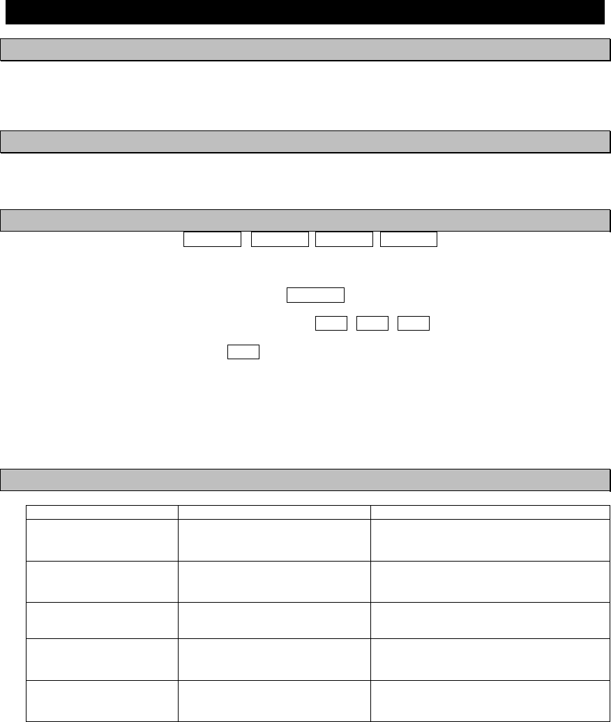
8.3.5 Supported interface sentences
(1)Supported interface sentences
Supported Sentence
Indication Format Input data sentences
Positioning system:
Longitude/Latitude
Position Accuracy
GNS, GLL,GGA,RMC
Datum Reference DTM
Speed Over Ground (SOG) VBW,VTG,RMC
Course Over Ground (COG) RMC,VTG
Heading HDT,THS
RAIM indicator GBS
1
SENSOR1̪
SENSOR2̪
SENSOR3
IEC61162-1/2
(NMEA1.5-2.3)
Rate Of Turn (ROT) ROT
2 SENSOR4 IEC61162-1 The above VHW,POS
3 SENSOR4 ITU-R M.823-2 RTCM SC-104 Ver.2.0 Type 1, 2, 7, 9 Binary data
4 SENSOR3 IEC61162-1 Heading HDT
5 AUX1̪,AUX2 IEC61162-2
Input: ABM, ACA, ACK, AIQ, AIR, BBM, EPV, LRI, LRF, POS,
SSD, SPW, VDO, VDM, VSD
Output: ABK, ACA, ACK, ACS, ALR, DSC, DSR, EPV, HBT, LRI,
LRF, LR1,䎃LR2,䎃LR3, NAK , SSD, SPW, TXT, TRL,VDO, VDM,
VSD, VER
6 AUX3 IEC61162-2
Output: ABK, ACA, ACK, ACS, ALR, DSC, DSR, EPV, HBT, LRI,
LRF, LR1,䎃LR2,䎃LR3, NAK , SSD, SPW, TXT, TRL,VDO, VDM,
VSD, VER
7 Long range IEC61993-2 Input: LRI,LRF, Output: LRF, LR1,LR2,LR3
8 BIIT ALARM IEC61993-2
9 Pilot̪ IEC61162-2
Input: ABM, ACA, ACK, AIQ, AIR, BBM, EPV, LRI, LRF, POS,
SSD, SPW, VDO, VDM, VSD
Output: ABK, ACA, ACK, ACS, ALR, DSC, DSR, EPV, HBT, LRI,
LRF, LR1,䎃LR2,䎃LR3, NAK , SSD, SPW, TXT, TRL,VDO, VDM,
VSD, VER
Note) When NQE-5183 connection box is equipped, all sentence are available.
When it is not equipped, 4 terminations which added ̪ mark can be available.
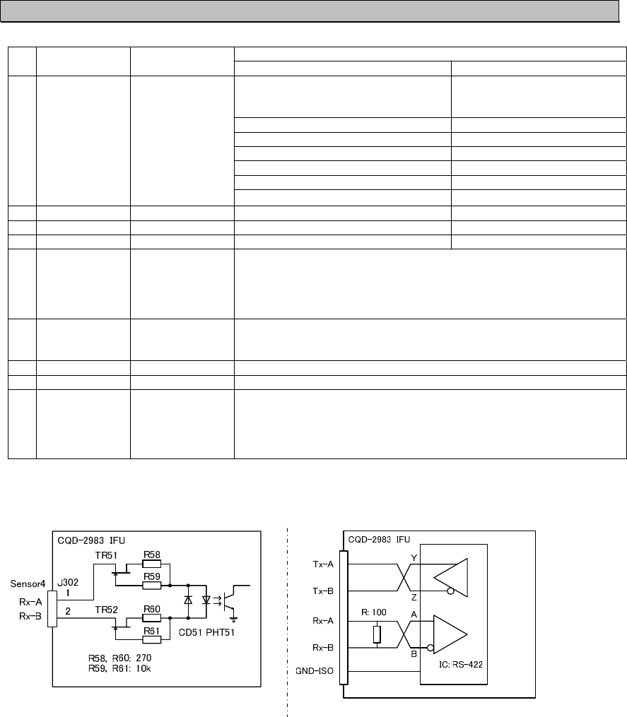
(2)Electrical description interface
Sensor4 AUX1-3, Sensor1-3
Load requirements
Current consumption: 2mA at 2V or less
Maximum input voltage: ±15V or more
Recommended operating current: 2mA or more
Note: IEC61162-2 interfaces comply with the following specifications.
- Output drive capacity: Differential driver output voltage is 2.0V or more (RL=100 ohms), Driver output
current 50mA
- Load on the line of inputs: 100 ohms. 1 IEC61162-2 output can drive 1 IEC61162-2 input.
- Electrical isolation of input circuits: Input circuits are electrically isolated from internal circuit with
opt-isolator.
- The input impedance for the non terminated Sensor1/2/3: between 333k and 357k ohms.
Sensor1; R51, IC504(CDJ-2983) AUX1; R54, IC506(CDJ-2983)
Sensor2; R52, IC505(CDJ-2983) AUX2; R55, IC55
Sensor3; R53, IC53 AUX3; R56, IC56
AUX4; R57, IC57

8-4
(2.1) List of sentences and associated data fields
(2.1.1) ABK – Addressed and binary broadcast acknowledgement
$--ABK,xxxxxxxxx,a,x.x,x,x*hh<CR><LF>
Type of acknowledgement
Message Sequence Number
ITU-R M.1371 message ID
AIS channel of reception
MMSI of the addressed destination AIS unit
(2.1.2) ABM – Addressed Binary and safety related Message
!--ABM,x,x,x,xxxxxxxxx,x,x.x,s--s,x*hh<CR><LF>
Number of fill-bits, 0 to 5
Encapsulated data
ITU-R M.1371 message ID (6 or 12)
AIS channel for broadcast of the radio message
The MMSI of destination AIS unit for the ITU-R M.1371 message
Sequential Message identifier, 0 to 3
Sentence number, 1 to 9
Total number of sentences needed to transfer the message, 1 to 9
(2.1.3) ACA – AIS Regional Channel Assignment Message
Time of "in-use" change
In-Use Flag
Information source
Power level control
Tx/Rx mode control
Channel B bandwidth
Channel B
$--ACA,x,llll.ll,a,yyyyy.yy,a,llll.ll,a,yyyyy.yy,a,x,xxxx,x,xxxx,x,x,x,a,x,hhmmss.ss*hh<CR><LF>
Channel A bandwidth
Channel A
Transition Zone Size
Region Southwest corner longitude – E/W
Region Southwest corner latitude – N/S
Region Northeast corner longitude – E/W
Region Northeast corner latitude – N/S
Sequence Number, 0 to 9
(2.1.4) ACS – Channel management information Source
$--ACS,x,xxxxxxxxx,hhmmss.ss,xx,xx,xxxx*hh<CR><LF>
UTC year
UTC month, 01 to 12
UTC day, 01 to 31
UTC at receipt of regional operating settings
MMSI of originator
Sequence number 1, 0 to 9

8-5
(2.1.5) ACK – Acknowledge alarm
$--ACK, xxx*hh<CR><LF>
Unique alarm number at alarm source
(2.1.6) ALR – Set alarm state
$--ALR,hhmmss.ss,xxx,A,A,c--c*hh<CR><LF>
Alarm’s description text
Alarm’s acknowledge state, A = acknowledged
V = unacknowledged
Alarm condition (A = threshold exceeded, V = not exceeded)
Unique alarm number (identifier) at alarm source
Time of alarm condition change, UTC
(2.1.7) AIR – AIS Interrogation Request
Message sub-section (Reserved for future use)
Number of message requested from station-2
MMSI of interrogated station-2
$--AIR,xxxxxxxxx,x.x,x,x.x,x,xxxxxxxxx,x.x,x*hh<CR><LF>
Message sub-section (Reserved for future use)
Number of second message from station-1
Message sub-section (Reserved for future use)
ITU-R M.1371 message requested from station-1
MMSI of interrogated station-1
(2.1.8) BBM – Broadcast Binary Message
!--BBM,x,x,x,x,x.x,s--s,x*hh<CR><LF>
Number of fill-bits, 0 to 5
Encapsulated data
ITU-R M.1371 message ID, 8 or 14
AIS channel for broadcast of the radio message
Sequential message identifier, 0 to 9
Sentence number, 1 to 9
Total number of sentences needed to transfer the message, 1 to 9
(2.1.9) DSC – Digital selective calling information
$ --DSC,xx,xxxxxxxxxx,xx,xx,xx,x.x,x.x,xxxxxxxxxx,xx,a,a*hh<CR><LF>
Expansion indicator
Acknowledgement
Nature of distress
MMSI of ship in distress
Time or Tel. No.
Position or Channel/frequency
Type of communication or second telecommand
Nature of distress or first telecommand
Category
Address
Format specifier

8-6
(2.1.10) DSR – DSC transponder response
$--DSR,x,x,xxxxxxxxxx,xx,c--c,......,xx,c--c,a*hh<CR><LF>
Expansion indicator
Data Set ’n’
Additional data sets
Data set ‘1’
Vessel MMSI
Message number
Total number of messages
(2.1.11) DTM – Datum reference
$--DTM,ccc,a,x.x,a,x.x,a,x.x,ccc*hh<CR><LF>
Reference datum WGS84 = W84
Altitude offset, m WGS72 = W72
Lon offset, min, E/W SGS85 = S85
Lat offset, min, N/S PE90 = P90
Local datum subdivision code
Local datum: WGS84 = W84
WGS72 = W72
SGS85 = S85
PE90 = P90
User defined = 999
IHO datum code
(2.1.12) EPV – Command or report equipment property value
$--EPV,a,c--c,c--c,x.x,c--c,*hh<CR><LF>
Value of property to be set
Property identifier for the property to be set
Unique identifier
Destination equipment type
Sentence status flag

8-7
(2.1.13) GBS – GNSS satellite fault detection
GNSS System ID
GNSS Signal ID
$--GBS, hhmmss.ss, x.x, x.x, x.x, xx, x.x, x.x, x.x, h, h *hh <CR><LF>
Standard deviation of bias estimate
Estimate of bias on most likely failed satellite (in metres)
Probability of missed detection for most likely failed satellite
ID number of most likely failed satellite
Expected error in altitude
Expected error in longitude
Expected error in latitude
UTC time of the GGA or GNS fix associated with this sentence
(2.1.14) GGA – Global positioning system (GPS) fix data
Differential reference station ID, 0000-1023
Age of differential GPS data
Units of geoidal separation,m
Geoidal separation
Units of antenna altitude, m
Antenna altitude above/below mean sea level (geoid)
Horizontal dilution of precision
$--GGA, hhmmss.ss, llll.ll, a, yyyyy.yy, a, x, xx, x.x, x.x, M, x.x, M, x.x, xxxx*hh<CR><LF>
Number of satellites in use, 00-12, may be different from the number in view
GPS quality indicator
Longitude E/W
Latitude N/S
UTC of position
(2.1.15) GNS – GNSS fix data
Navigational status indicator
Differential reference station ID
Age of differential data
Geoidal separation, m
Antenna altitude, m, re:mean-sea-level (geoid)
$--GNS, hhmmss.ss, llll.ll, a, yyyyy.yy, a, c---c, xx, x.x, x.x, x.x, x.x, x.x, a*hh<CR><LF>
HDOP
Total number of satellites in use, 00-99
Mode indicator: N = No fix, A = Autonomous, D = Differential,
P = Precise, R = Real Time Kinematic, F = Float RTK,
E = Estimated, M = Manual input, S = Simulator
Longitude, E/W
Latitude, N/S
UTC of position

8-8
(2.1.16) GLL – Geographic position – Latitude/longitude
$--GLL, llll.ll, a, yyyyy.yy, a, hhmmss.ss, A, a *hh<CR><LF>
Longitude, E/W
(2.1.17) HDT – Heading true
$--HDT, x.x, T*hh<CR><LF>
Heading, degrees true
(2.1.18) LRI – Long-Range Interrogation
Longitude – E/W (south-west co-ordinate)
Latitude – N/S (south-west co-ordinate)
$--LRI,x,a,xxxxxxxxx,xxxxxxxxx,llll.ll,a,yyyyy.yy,a,llll.ll,a,yyyyy.yy,a*hh<CR><LF>
Longitude – E/W (north-east co-ordinate)
Latitude – N/S (north-east co-ordinate)
MMSI of "destination"
MMSI of "requestor"
Control Flag
Sequence number, 0 to 9
(2.1.19) LRF – Long Range Function
$--LRF,x,xxxxxxxxx,c--c,c--c,c--c*hh<CR><LF>
Function reply status
Function request, 1 to 26 characters
Name of requestor, 1 to 20 character string
MMSI of requestor
Sequence number, 0 to 9
(2.1.20) LR1 – Long-range Reply with destination for function request "A"
$--LR1,x,xxxxxxxxx,xxxxxxxxx,c--c,c--c,xxxxxxxxx*hh<CR><LF>
IMO Number, 9-digit number
Call Sign, 1 to 7 characters
Ship's name, 1 to 20 characters
MMSI of requestor (reply destination)
MMSI of responder
Sequence Number, 0 to 9
Latitude,N/S
UTC of position
Status Mode indicator

8-9
(2.1.21) LR2 – Long-range Reply for function requests "B, C, E, and F"
Speed over ground, value to 0,1 knot
Course over ground True, value to nearest degree
Longitude, E/W (position co-ordinate, to 1 min.)
$--LR2,x,xxxxxxxxx,xxxxxxxx,hhmmss.ss,llll.ll,a,yyyyy.yy,a,x.x,T,x.x,N*hh<CR><LF>
Latitude, N/S (position co-ordinate, to 1 min.)
UTC time of position
Date: ddmmyyyy, 8 digits
MMSI of responder
Sequence Number, 0 to 9
(2.1.22) LR3 – Long-range Reply for function requests "I, O, P, U and W"
Persons, 0 to 8191
Ship type
Ship breadth, value to nearest m
Ship length, value to nearest m
$--LR3,x,xxxxxxxxx,c--c,xxxxxx,hhmmss.ss,x.x,cc,x.x,x.x,x.x,x.x*hh<CR><LF>
Ship/cargo
Draught, value to 0,1 m
ETA Time, value to nearest second
ETA Date: ddmmyy
Voyage destination, 1 to 20 characters
MMSI of "responder"
Sequence Number, 0 to 9
(2.1.23) NAK – Negative acknowledgement
$--NAK,cc,ccc,c--c,x.x,c--c*hh<CR><LF>
Negative acknowledgement’s descriptive text
Reason code for negative acknowledgement
Unique identifier
Affected sentence formatter
Talker identifier

8-10
(2.1.24) RMC – Recommended minimum specific GNSS data
Navigational status
$--RMC, hhmmss.ss, A, llll.ll,a, yyyyy.yy, a, x.x, x.x, xxxxxx, x.x,a, a, a*hh<CR><LF>
Mode indicator
Magnetic variation,
degrees, E/W
Date: dd/mm/yy
Course over ground, degrees true
Speed over ground, knots
Longitude, E/W
Latitude, N/S
Status A = data valid V = navigation receiver warning
UTC of position fix
(2.1.25) ROT – Rate of turn
$--ROT, x.x, A*hh<CR><LF>
Status: A = data valid
V = data invalid
Rate of turn, °/min, "-" = bow turns to port
(2.1.26) SPW – Security password sentence
$--SPW,ccc,c--c,x,c--c*hh<CR><LF>
Password
Password level
Unique identifier
Password protected sentence
(2.1.27) SSD – Ship Static Data
$--SSD,c--c,c--c,xxx,xxx,xx,xx,c,aa*hh<CR><LF>
Source identifier
DTE indicator flag
Pos. ref., "D," distance from starboard beam, 0 to 63 m
Pos. ref., "C," distance from port beam, 0 to 63 m
Pos. ref., "B," distance from stern, 0 to 511 m
Pos. ref., "A," distance from bow, 0 to 511 m
Ship's Name, 1 to 20 characters
Ship's Call Sign, 1 to 7 characters

8-11
(2.1.28) TXT – Text transmission
$--TXT,xx,xx,xx,c--c*hh<CR><LF>
Text message
Text identifier
Sentence number, 01 to 99
Total number of sentences, 01 to 99
(2.1.29) TRL – AIS transmitter non functioning log
$--TRL,x.x,x.x,x,xxxxxxxx,xxxxxxxx,hhmmss.ss,xxxxxxxx,hhmmss.ss,x,*hh<CR><LF>
Reason code
Switch on UTC time
Switch on date
Switch off UTC time
Switch off date
Sequential message identifier
Log entry number
Total number of log entries
(2.1.30) VBW – Dual ground/water speed
$--VBW, x.x, x.x, A, x.x, x.x, A, x.x, A, x.x, A*hh<CR><LF>
Status: stern ground speed,
A = data valid, V = data invalid
Stern transverse ground speed, knots
Status: stern water speed,
A = data valid, V = data invalid
Stern transverse water speed, knots
Status, ground speed,
A = data valid, V = data invalid
Transverse ground speed, knots
Longitudinal ground speed, knots
Status: water speed, A = data valid, V = data invalid
Transverse water speed, knots
Longitudinal water speed, knots
(2.1.31) VDM – VHF Data-link Message
!--VDM,x,x,x,a,s--s,x*hh<CR><LF>
Number of fill-bits, 0 to 5
Encapsulated ITU-R M.1371 radio message
AIS Channel, "A" or "B"
Sequential message identifier, 0 to 9
Sentence number, 1 to 9
Total number of sentences needed to transfer the message, 1 to 9

8-12
(2.1.32) VDO – VHF Data-link Own-vessel message
!--VDO,x,x,x,a,s--s,x*hh<CR><LF>
Number of fill-bits, 0 to 5
Encapsulated ITU-R M.1371 radio message
AIS Channel, "A" or "B"
Sequential message identifier, 0 to 9
Sentence number, 1 to 9
Total number of sentences needed to transfer the message, 1 to 9
(2.1.33) VSD – Voyage Static Data
$--VSD,x.x,x.x,x.x,c--c,hhmmss.ss,xx,xx,x.x,x.x*hh<CR><LF>
Regional application flags, 0 to 15
Navigational status, 0 to 15
Est. month of arrival at destination, 00 to 12(UTC)
Est. day of arrival at destination, 00 to 31 (UTC)
Est. UTC of destination arrival
Destination, 1-20 characters
Persons on-board, 0 to 8191
Maximum present static draught, 0 to 25,5 m
Type of ship and cargo category, 0 to 255
(2.1.34) VTG – Course over ground and ground speed
$--VTG, x.x, T, x.x, M, x.x, N, x.x, K,a*hh<CR><LF>
Mode indicator
Speed over ground, km/h
Speed over ground, knots
Course over ground, degrees magnetic
Course over ground, degrees true
8-13
8.4 Connection Box (NQE-5183 option)
8.4.1 Environmental condition
(1) Operating temperature : -15qC to +55qC (IEC 60945)
8.4.2 External interfaces (connected with NCM-983)
(1) Sensor data input ports SENSOR1 / SENSOR2/ SENSOR3
Four input ports meet the requirements of IEC 61162-1.
(2) Gyrocompass data input
Current loop 1 communication port (multiple use as SENSOR3)
(3) GNSS differential correction data input port SENSOR4
One input port meet the requirement of ITU-R M.823-2 on TTL level
(4) External display equipment communication ports AUX1 / AUX2 / AUX3
Three communication ports meet the requirements of IEC 61162-2
(5) Long range communication port AUX3
One communication port meets the requirements of IEC 61162-2
(6) Relay terminals ALR
One port for external alarm device
8.5 AC Power Supply Unit (NBD-577C option)
(1) Input voltage : 100 - 120 / 200 - 240 VAC ±10%, 50/60Hz Single phase
: 24VDC (backup power supply)
(2) Output voltage : Nominal 24VDC, 19 - 35VDC