Japan Radio JSS-296 MF/HF Radio Telephone User Manual 1
Japan Radio Co Ltd. MF/HF Radio Telephone 1
Contents
- 1. Pages 1 to 77
- 2. Pages 78 to 154
Pages 78 to 154
3-42
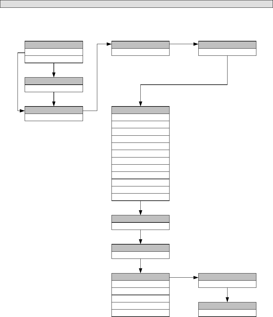
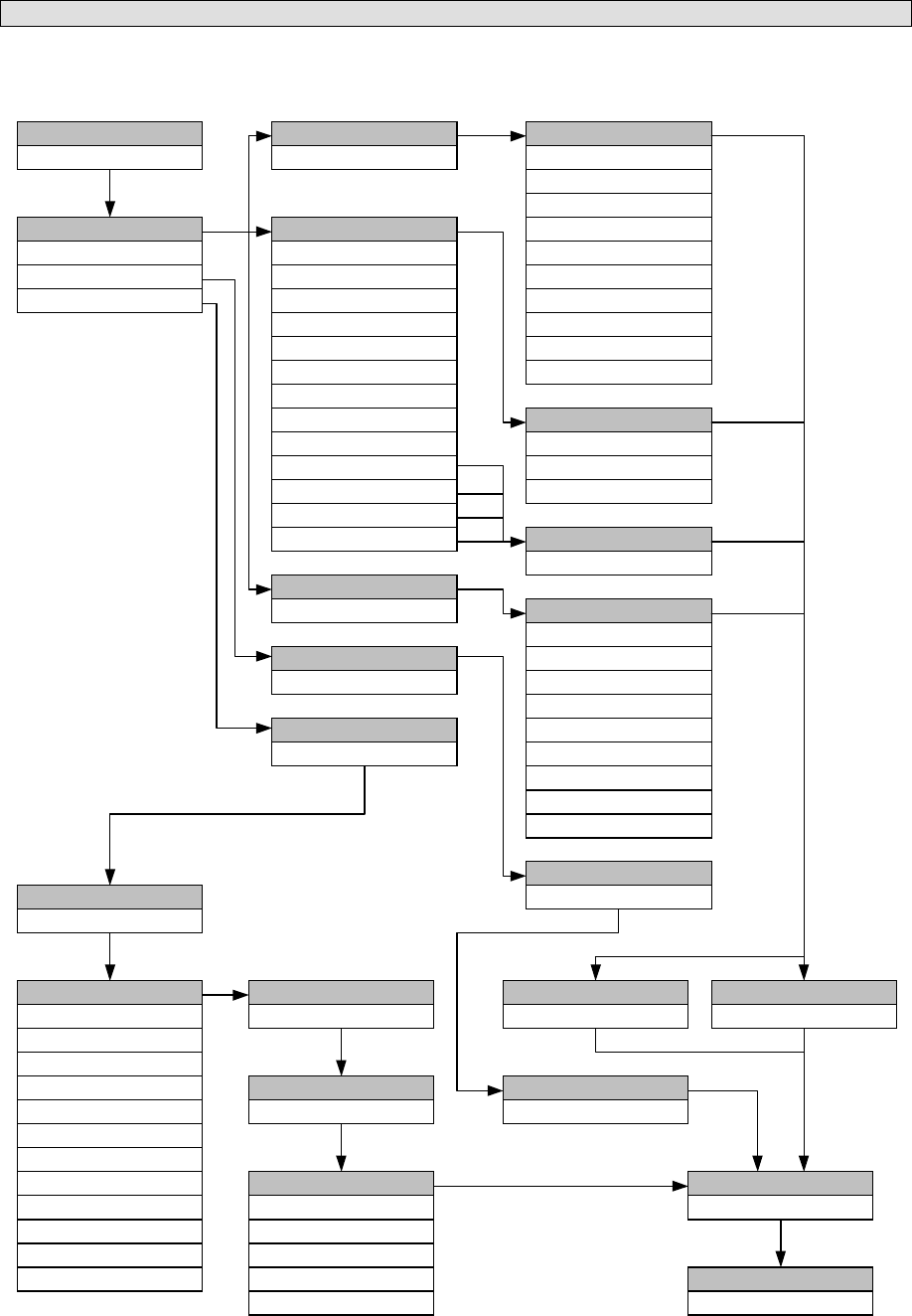
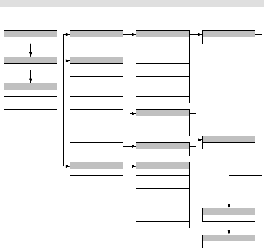
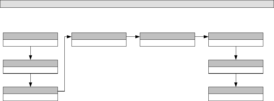
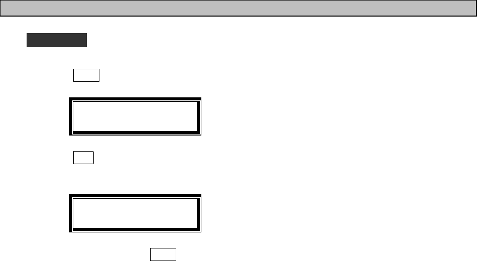
(4) DISTRESS RELAY CALL
Normally, a distress call is acknowledged by a coastal station, but if there is not acknowledgement by any station
(e.g., due to propagation, etc.) relay it after editing the message for a relay call by selecting this menu. Normally, a
distress relay is made by selecting this menu.
FORMAT
FORMATFORMAT
FORMAT
INDIVIDUAL
ADDRESS
ADDRESSADDRESS
ADDRESS
XXXXXXXXX
CALL TX/RX FREQ
CALL TX/RX FREQCALL TX/RX FREQ
CALL TX/RX FREQ
2187.5/2187.5
EOS
EOSEOS
EOS
EOS
DIST-ADDRESS
DIST-ADDRESSDIST-ADDRESS
DIST-ADDRESS
NATURE
NATURENATURE
NATURE
DIST-POTISION
DIST-POTISIONDIST-POTISION
DIST-POTISION
12°34'N123°45'E
DIST-UTC
DIST-UTCDIST-UTC
DIST-UTC
12:34
DIST-TELECOMM
DIST-TELECOMMDIST-TELECOMM
DIST-TELECOMM
J3E TEL
F1B/J2B FEC TTY
F1B/J2B ARQ TTY
F3E/G3E SIMP TEL
F3E/G3E DUP TEL
TELECOMMAND-1
TELECOMMAND-1TELECOMMAND-1
TELECOMMAND-1
XXXXXXXXXALL SHIPS
DISTRESS
CATEGORY
CATEGORYCATEGORY
CATEGORY
DISTRESS RELAY
UNDESIGNATED DIST
ABANDONING
EPIRB EMISSION
FIRE/EXPLOSION
FLOODING
COLLISION
GROUNDING
LISTING
SINKING
DISABLED/ADRIFT
PIRACY/ROBBERY
MAN OVERBOARD
3-43
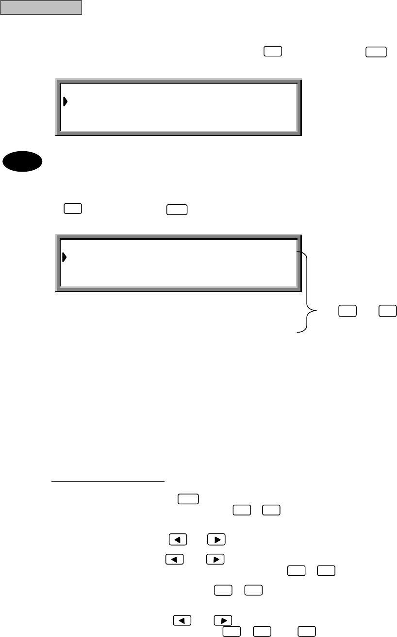
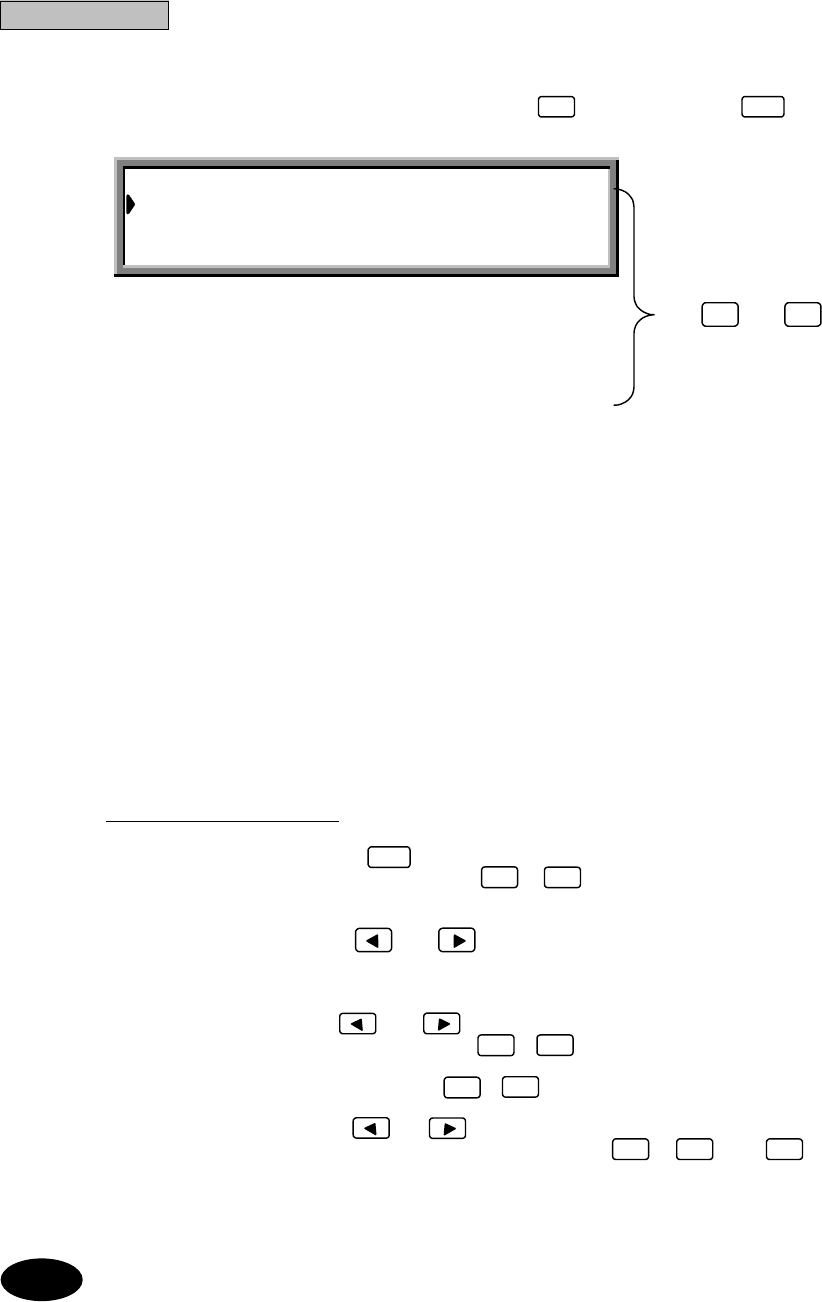
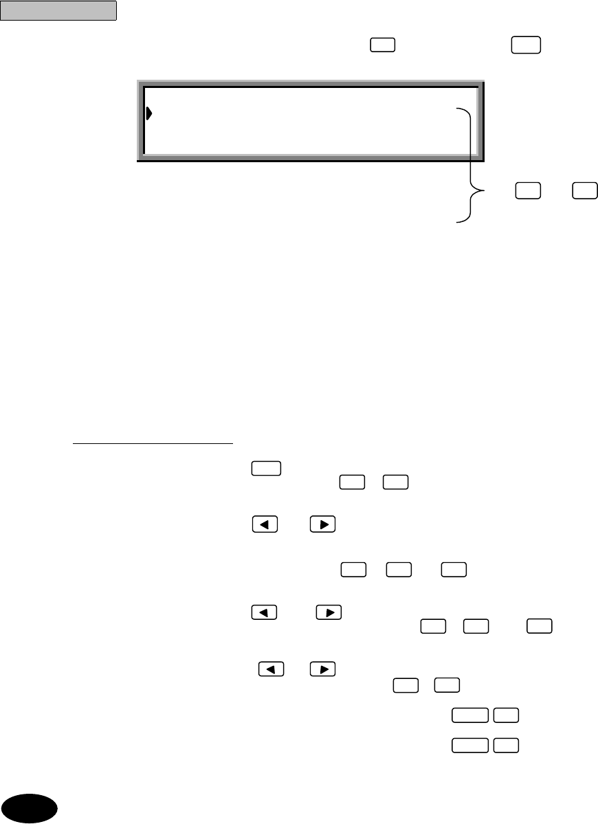
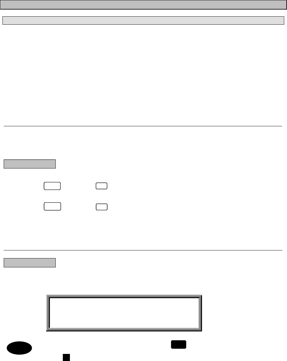
ALL SHIP’S DIST−RELAY
Dist-address :XXXXXXXXX
Nature :UNDESIGNATED DIST
Dist-position :12゚34’N123゚45’E
Dist-UTC :01:20
Dist-telecomm :J3E TEL
Call TX/RX freq: 2,187.5 / 2,187.5 kHz
Use and to
scroll the screen.
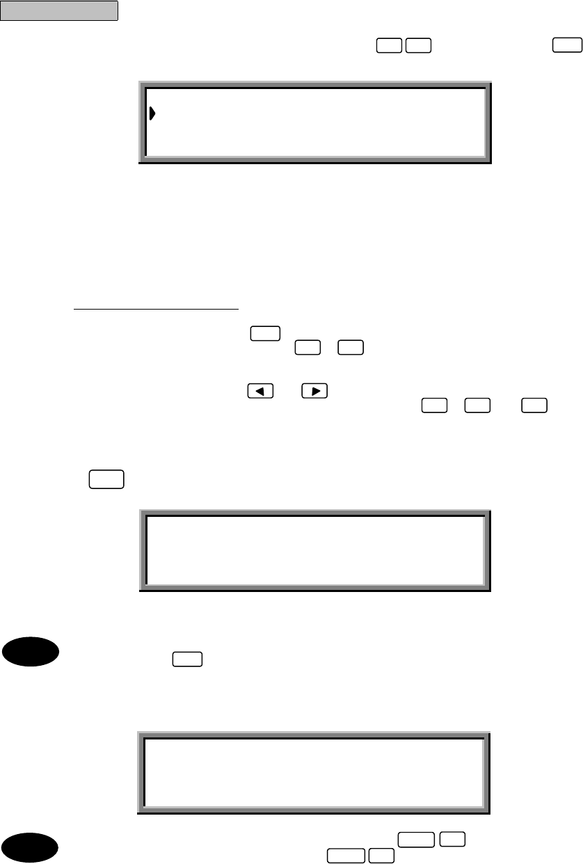
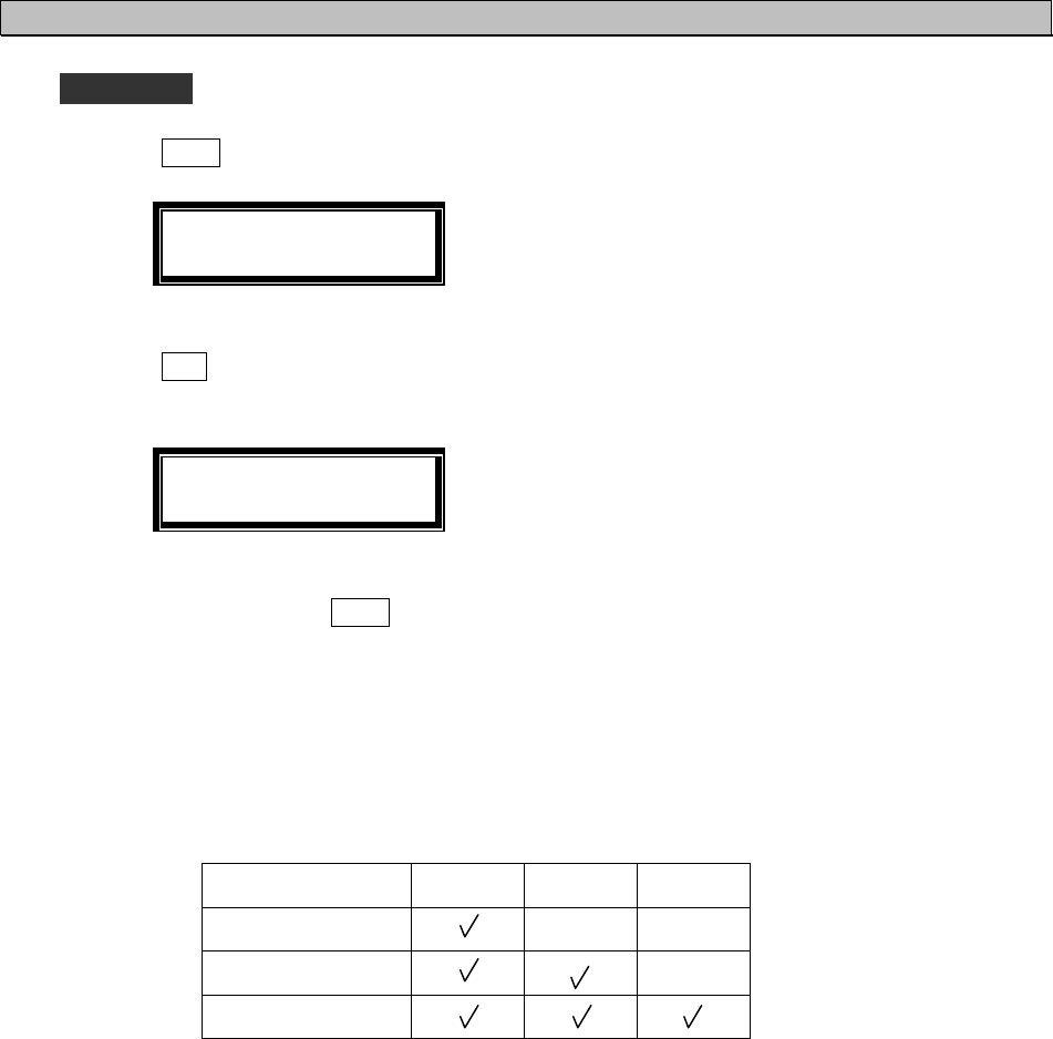
Procedure
Example: Procedure of a distress relay call to all ships
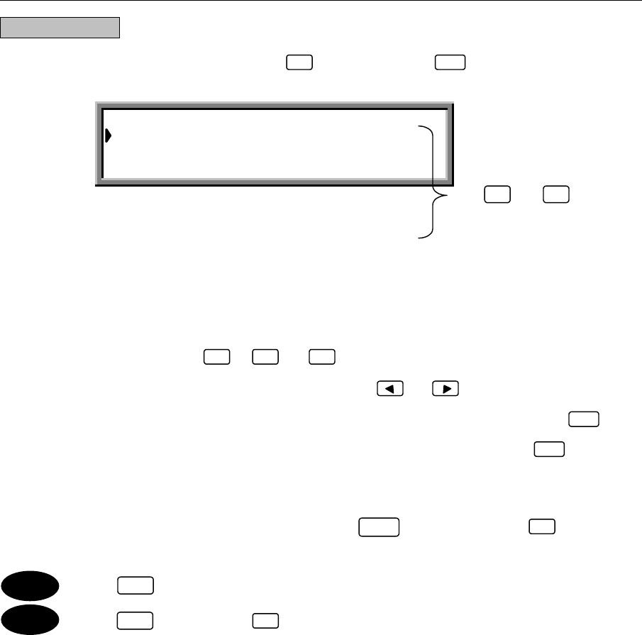
1. From the "MENU#1-EDIT&CALL" screen, press
, and then press
.
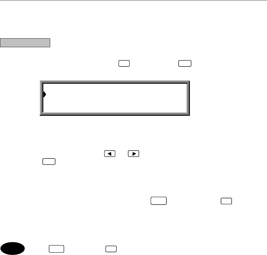
The "DISTRESS RELAY CALL" screen is displayed.
1. Select 1 to relay the call to all ships and coastal stations.
2. Select 2 to relay the call to an individual ship or coastal station.
2. Press
. and then press
.
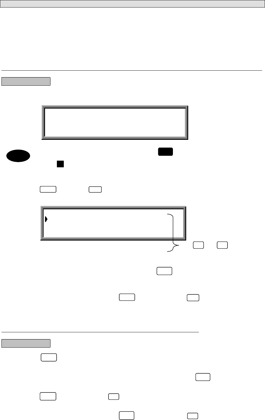
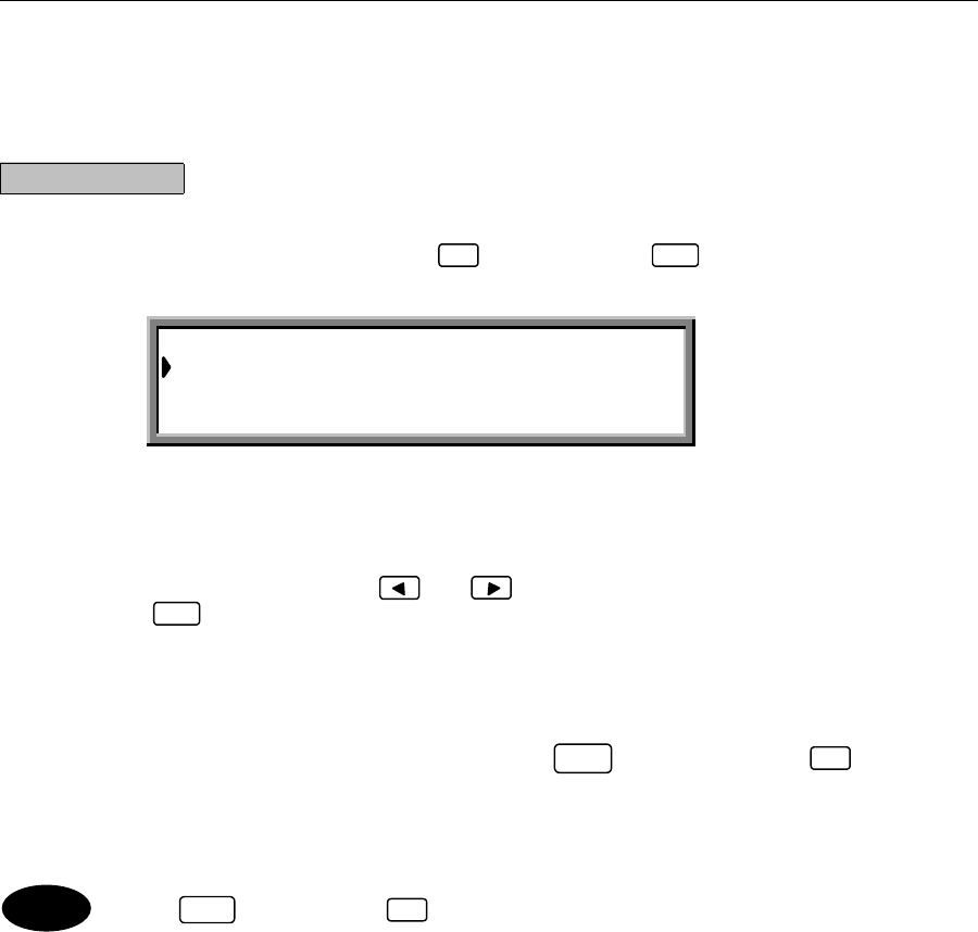
The "ALL SHIPS DIST-RELAY" screen is displayed.
The following items have been set in this example.
「Dist-address」:XXXXXXXXX
「Nature」:UNDESIGNATED DIST
「Dist-position」:12 ゚34’N123 ゚45’E
「Dist-UTC」:01:20
「Dist-telecomm」:J3E TEL
「Call TX/RX freq」:2,187.5/2,187.5 kHz
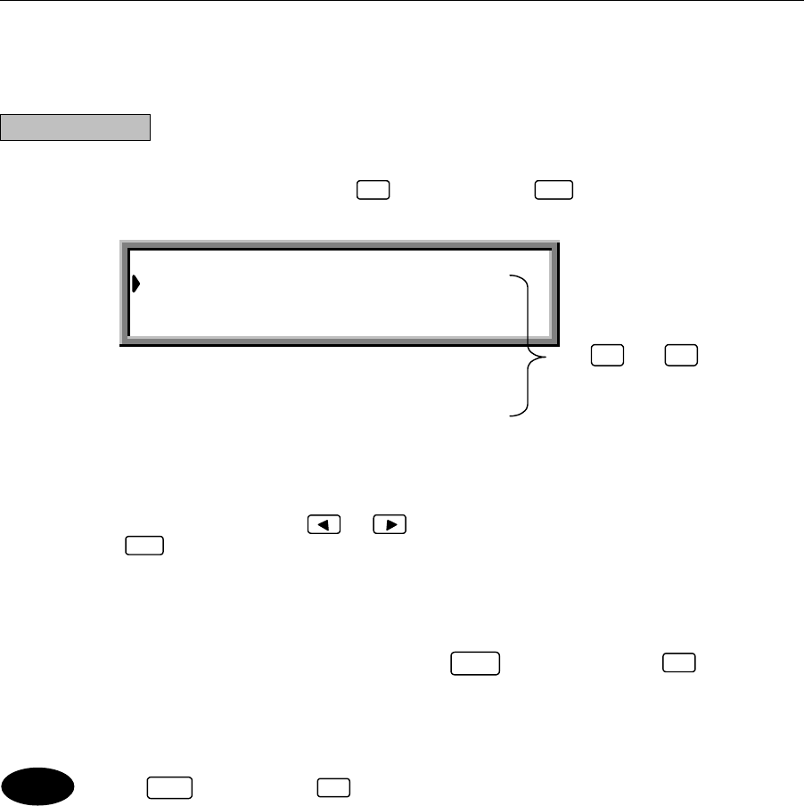
●Entering the respective items:
After selecting each item, press to confirm the selection.
(1) Dist-address: Use the numerical keys ( to ) to enter the address of the receiving
station (ship or coastal station).
(2) Nature
Dist-telecomm: Use the and keys to select the items.
(3) Dist-position: Use the and keys to determine the direction, and then input the
ship's position using the numerical keys ( to ).
(4) Dist-UTC: Use the numerical keys ( to ) to enter the time.
(4) Call TX/RX freq: Use the and keys to select one of the preset frequencies, or use
the numerical keys ( to ,and ) to specify a frequency directly.
4ENT
ENT
0 9
0 9
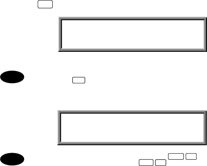
DISTRESS RELAY CALL Select no.__
1.ALL SHIP’S DIST rly EDIT
2.INDIVIDUAL DIST rly EDIT
1ENT
0 9
▲
▼
Note
0 9 .

3-44
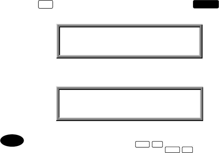
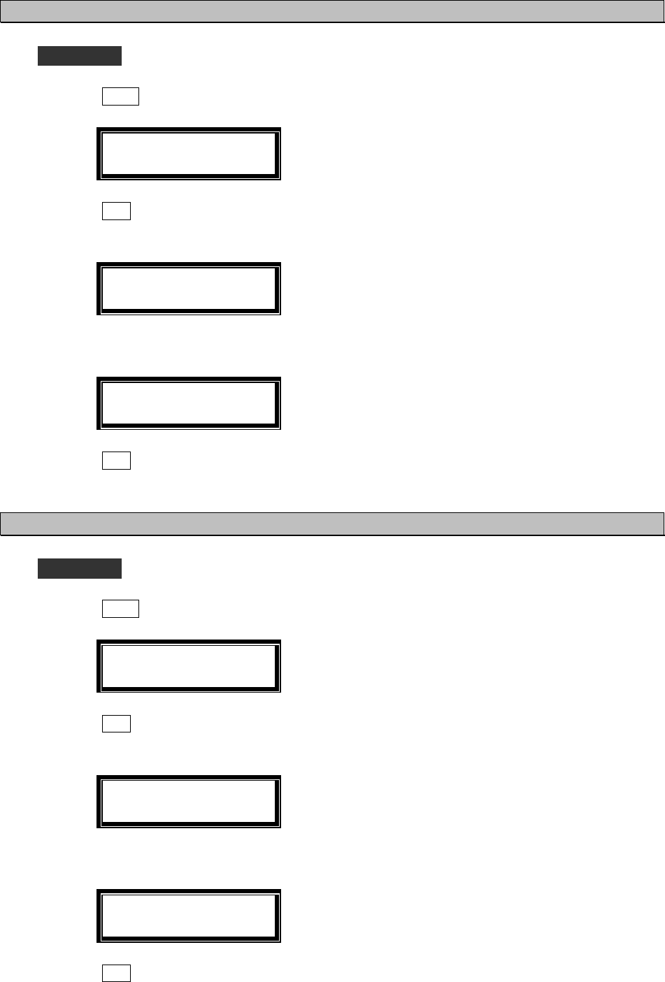
3. Press
, and then open the cover on the left and press
for at least 3
seconds (until the intermittent alarm tone changes to a continuous tone).
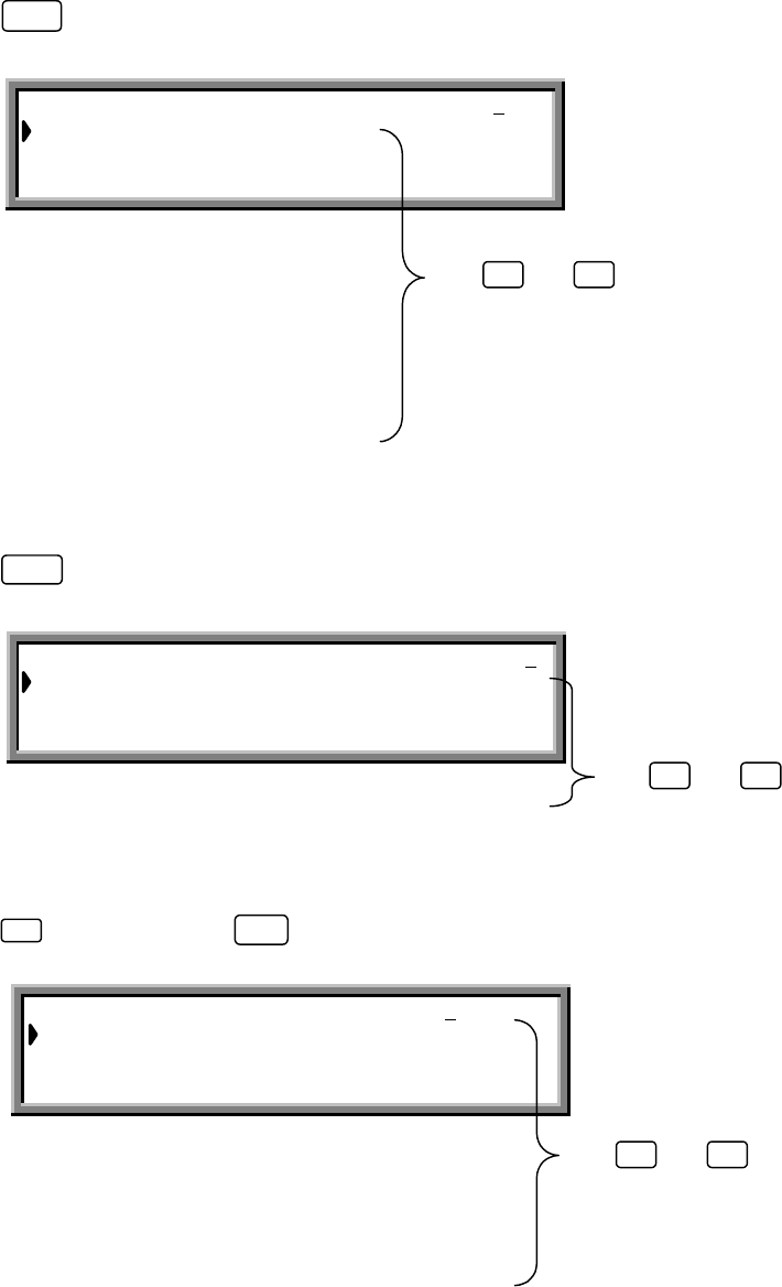
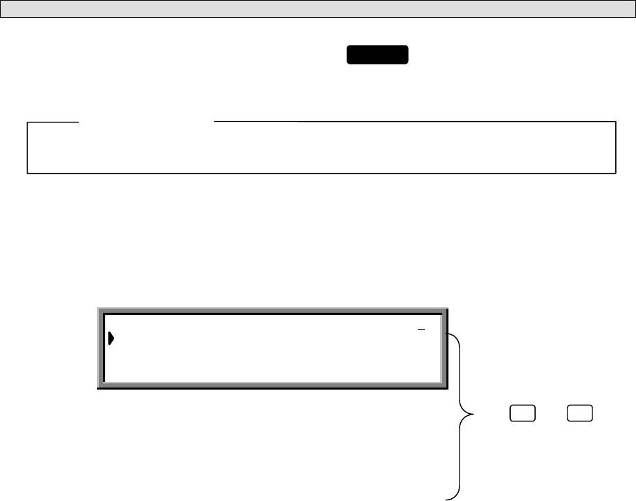
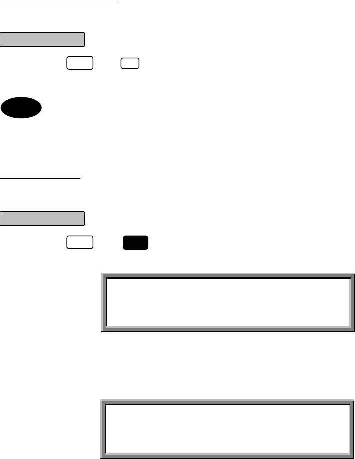
The following screen is displayed and the message is transmitted.
・
Press to cancel the DISTRESS transmission.
・
To discard the message and quit without sending it, press (QUIT).
・
Unable to save the message.
CALL
ALL SHIP’S DIST-RELAY Transmitting
TX frequency : 2,187.5 kHz
TX date&time : 06.Sep.2001(Thu) 01:30
DISTRESS
FUNC 4
STOP
Note
3-45
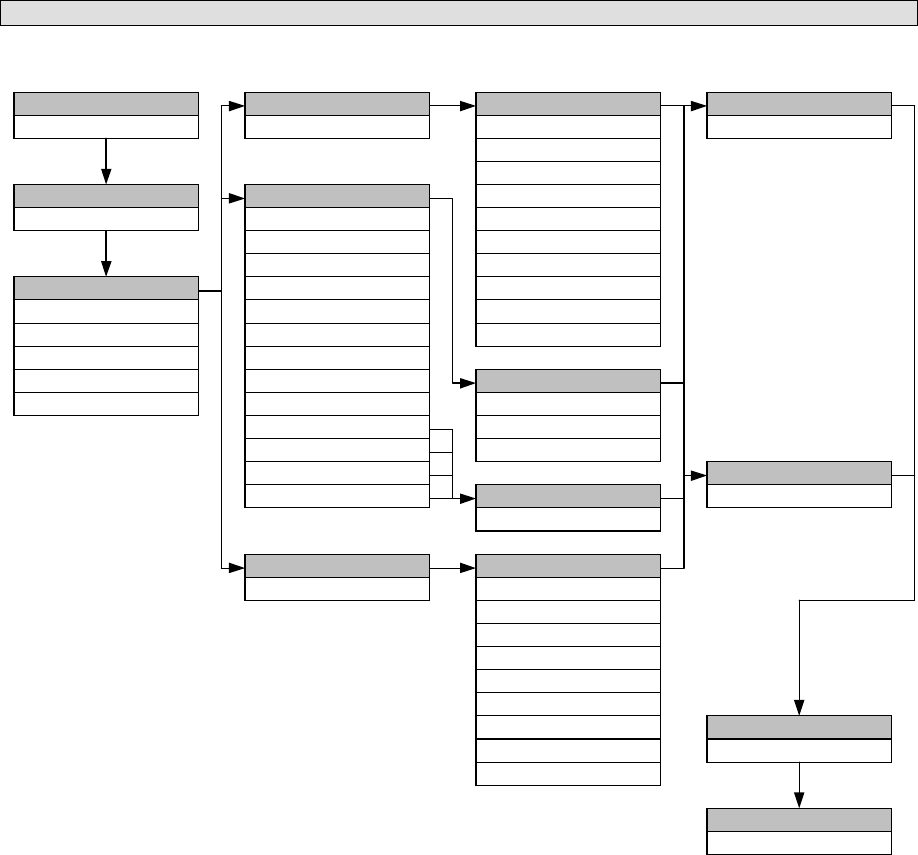
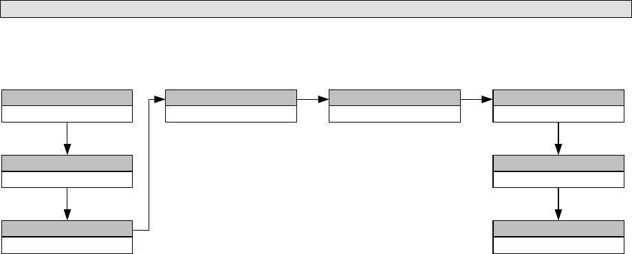
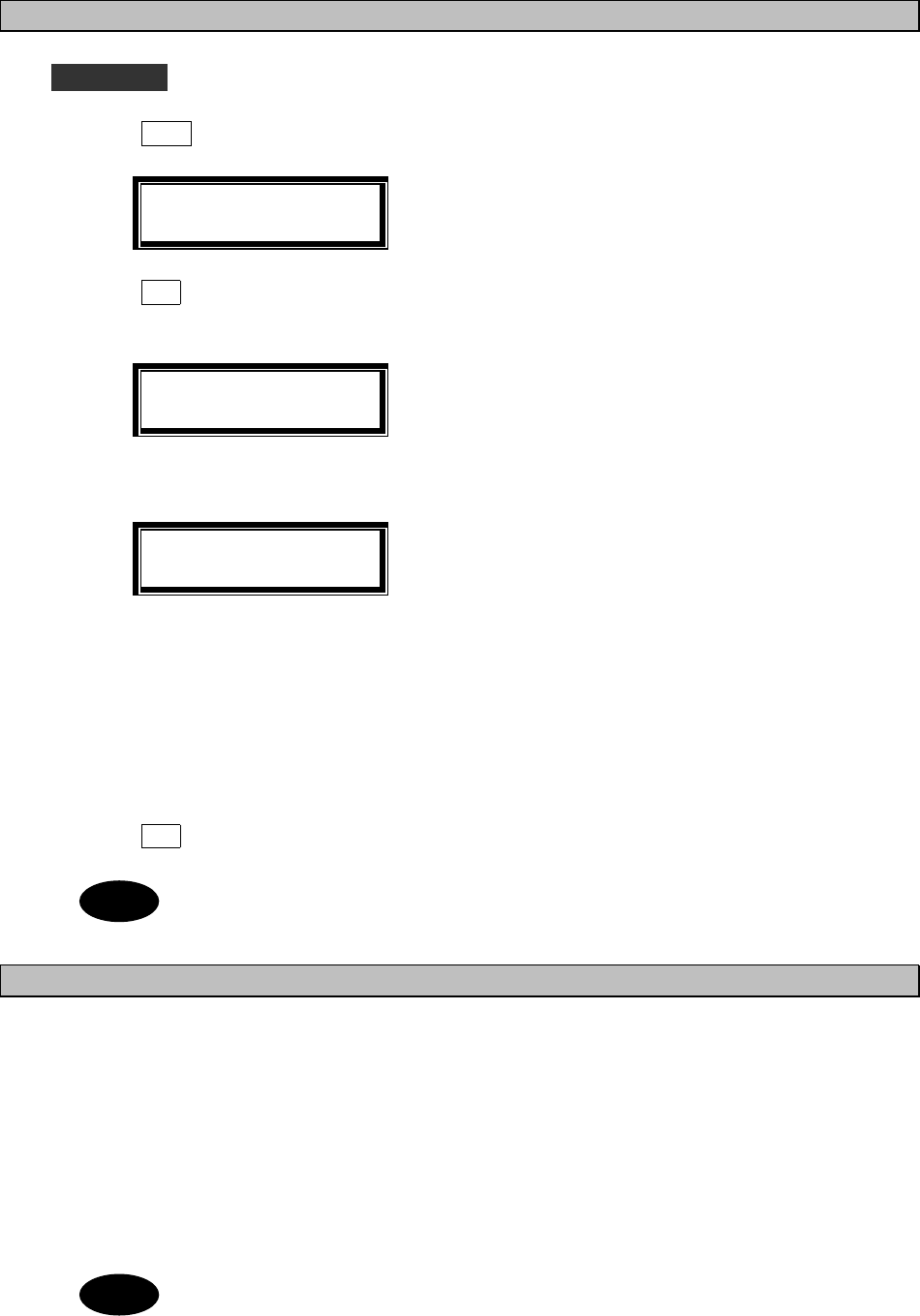
(5) AUTO/SEMI-AUTO CALL
This mode is available only to coastal stations where the telephone on board can be connected on-line to a public
line on the land after DSC communication on the MF/HF band.
FORMAT
FORMATFORMAT
FORMAT
AUTO/SEMI SVC
ADDRESS
ADDRESSADDRESS
ADDRESS
XXXXXXXXX
CATEGORY
CATEGORYCATEGORY
CATEGORY
ROUTINE
TELECOMMAND-1
TELECOMMAND-1TELECOMMAND-1
TELECOMMAND-1
J3E TEL
F1B/J2B FEC TTY
F1B/J2B ARQ TTY
F1B/J2B REC TTY
F1B/J2B TTY
A1A MORSE RECORD
SHIP'S POSITION
A1A MORSE KEY
F1C/F2C/F3C FAX
NO INFORMATION
F3E/G3E SIMP TEL
F3E/G3E DUP TEL
POLLING
TELECOMMAND-2
TELECOMMAND-2TELECOMMAND-2
TELECOMMAND-2
NO INFORMATION
RES18 SHIP/AIR
MEDICALTRANS
PUB CALL OFFICE
TELECOMMAND-2
TELECOMMAND-2TELECOMMAND-2
TELECOMMAND-2
NO INFORMATION
ITU-T V.21
ITU-T V.22
ITU-T V.22 BIS
ITU-T V.23
ITU-T V.26 BIS
ITU-T V.26 TER
ITU-T V.27 TER
ITU-T V.32
SHIP'S POTISION
SHIP'S POTISIONSHIP'S POTISION
SHIP'S POTISION
12°34'N123°45'E
WORK TX/RX FREQ
WORK TX/RX FREQWORK TX/RX FREQ
WORK TX/RX FREQ
12345.6/12346.5
CALL TX/RX FREQ
CALL TX/RX FREQCALL TX/RX FREQ
CALL TX/RX FREQ
4208.0/4219.5
EOS
EOSEOS
EOS
ACK RQ
DATA MODEM
TELECOMMAND-1
TELECOMMAND-1TELECOMMAND-1
TELECOMMAND-1
TELEPHONE NO.
TELEPHONE NO.TELEPHONE NO.
TELEPHONE NO.
XXXXXXXXXXXXXXXX
UNCOMPLY
END OF CALL
3-46
Use and to
scroll the screen.
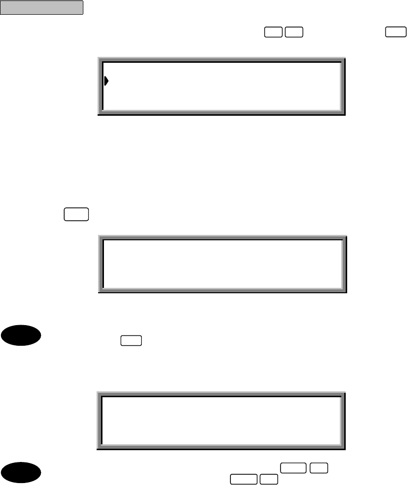
Procedure
1. From the "MENU#1-EDIT&CALL" screen, press
, and then press
.
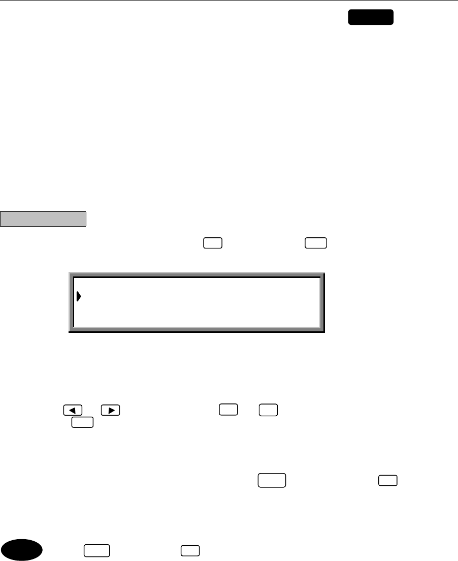
The "AUTO/SEMI-AUTO CALL" screen is displayed.
The following items have been set in this example.
「Address」:XXXXXXXXX
「Telecommand-1」:
J3E TEL
「Telecommand-2」:NO INFORMATION
「Ship’s position」:12 ゚34’N123 ゚45’E
「Telephone no.」:04224507XX
「Call TX/RX freq」:4,208.0/4,219.5 kHz
●Entering the respective items:
After selecting each item, press to confirm the selection.
(1) Address: Use the numerical keys ( to ) to enter the address of the receiving station
(ship or coastal station).
(2) Telecommand-1: Use the and keys to select the items.
Telecommand-2
(3) Ship's-position: Use the and keys to determine the direction, and then input the
ship's position using the numerical keys ( to ).
(4) Telephone no. Use the numerical keys ( to ) to enter the telephone number.
(5) Call TX/RX freq: Use the and keys to select one of the preset frequencies, or use
the numerical keys ( to ,and ) to specify a frequency directly.
(6) Other settings:
・"Work TX/RX freq": Use the numerical keys ( to , and ) to directly specify a
frequency.
・Switching from "Ship's position" to "Work TX/RX freq": Press (FREQ).
・Switching from "Work TX/RX freq" to "Ship's position": Press (POS).
ATTENTION
This call requires the auto/semi-auto call service of a coastal station.
Please ask the coastal station you use for details.
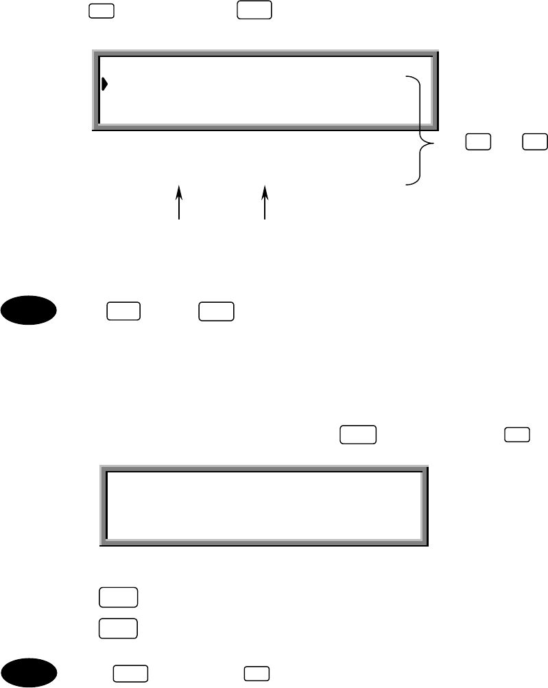
AUTO/SEMI-AUTO CALL Transmissible
Address :XXXXXXXXX
Telecommand-1 :J3E TEL
Telecommand-2 :NO INFORMATION
Ship’s position:12 ゚34’N123 ゚45’E
Telephone no. :04224507XX
Call TX/RX freq: 4,208.0/4,219.5kHz
0 9
09
FUNC 6
FUNC 5
ENT
5ENT
0 9
▲
▼
0 9 .
0 9 .
3-47
2. Press
The following screen is displayed and the message is transmitted.
If the tuner is not tuned to the transmission frequency, the "tuner mismatch!!" warning message is
displayed. Press to tune the tuner, then transmit the message.
When the transmission is completed, the following screen is displayed. After a brief interval, operation
returns to the "MENU#1-EDIT&CALL" screen.
To discard the message and quit without sending it, press (QUIT).
To store a message without sending it, press (SAVE).
CALL
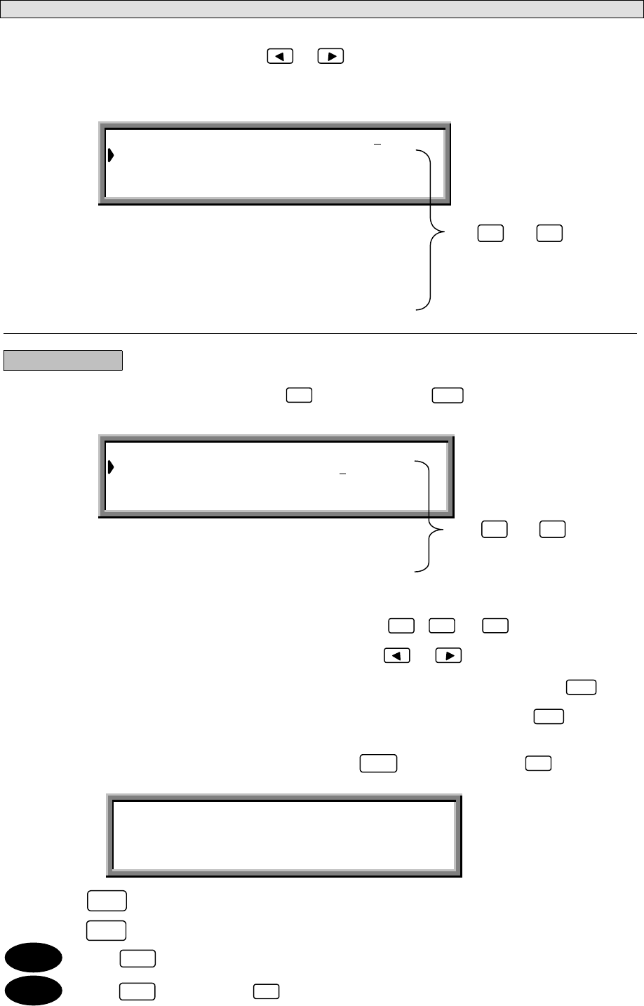
AUTO/SEMI-AUTO CALL Transmitting
TX frequency : 4,208.0 kHz
TX date&time :06.Sep.2001(Thu) 01:30
AUTO/SEMI-AUTO CALL Send Completed
TX frequency : 4,208.0 kHz
TX date&time :06.Sep.2001(Thu) 01:30
FUNC 9
ENT
FUNC 4
Note
Note
3-48
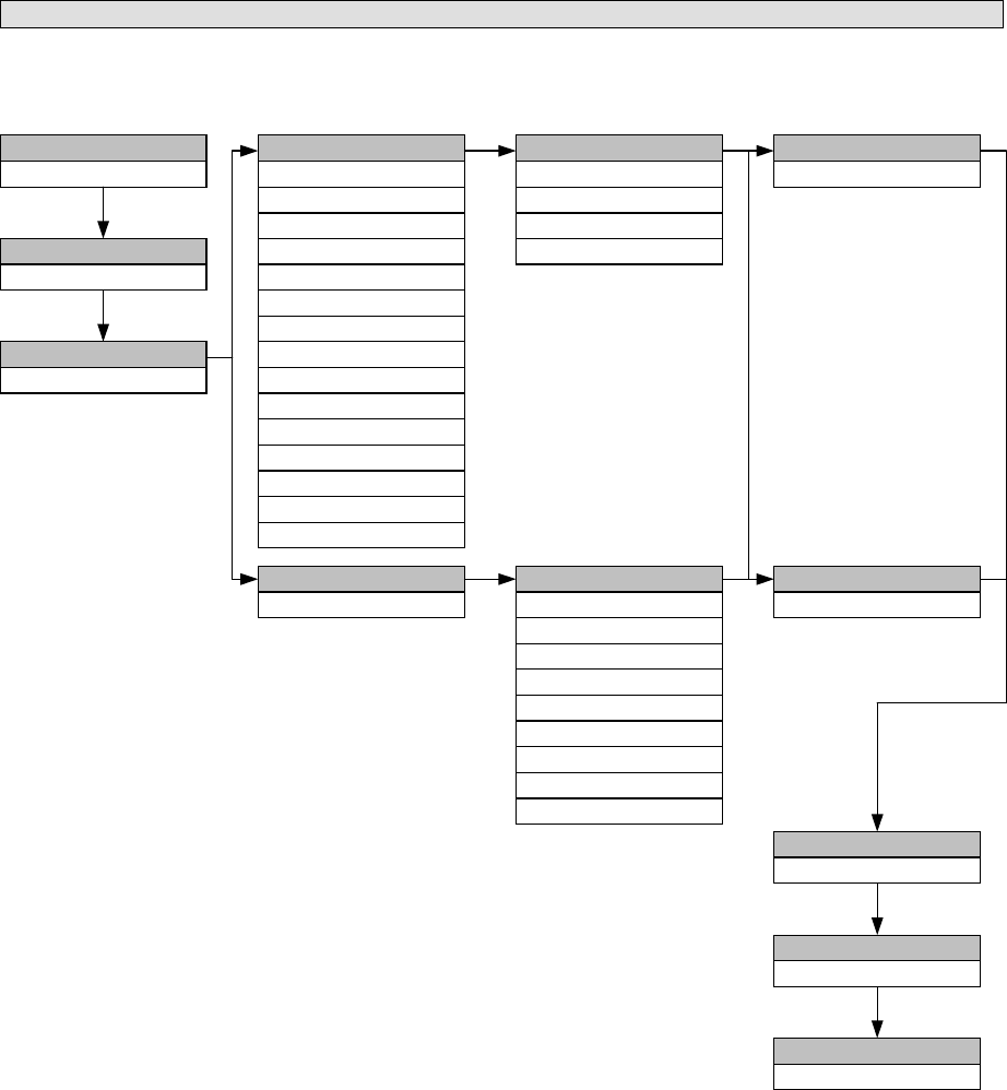
(6) ALL SHIPS CALL
An all ships call is transmitted to all ships. Normally, this feature is used to acknowledge when a distress call is
received and a distress acknowledgement from a coastal station has not been received in response.
FORMAT
FORMATFORMAT
FORMAT
CATEGORY
CATEGORYCATEGORY
CATEGORY
URGENCY
SAFETY
DISTRESS
TELECOMMAND-1
TELECOMMAND-1TELECOMMAND-1
TELECOMMAND-1
J3E TEL
F1B/J2B FEC TTY
F1B/J2B ARQ TTY
F1B/J2B REC TTY
F1B/J2B TTY
A1A MORSE RECORD
SHIP'S POSITION
A1A MORSE KEY
F1C/F2C/F3C FAX
NO INFORMATION
F3E/G3E SIMP TEL
F3E/G3E DUP TEL
POLLING
UNCOMPLY
TELECOMMAND-2
TELECOMMAND-2TELECOMMAND-2
TELECOMMAND-2
NO INFORMATION
RES18 SHIP/AIR
MEDICALTRANS
PUB CALL OFFICE
TELECOMMAND-2
TELECOMMAND-2TELECOMMAND-2
TELECOMMAND-2
NO INFORMATION
ITU-T V.21
ITU-T V.22
ITU-T V.22 BIS
ITU-T V.23
ITU-T V.26 BIS
ITU-T V.26 TER
ITU-T V.27 TER
ITU-T V.32
TELECOMMAND-2
TELECOMMAND-2TELECOMMAND-2
TELECOMMAND-2
NO REASON
CONGESTION
BUSY
QUEUE
STATION BARRED
NO OPERATOR
NO
-
OPR
TEMPORALITY
EQUIP DISABLED
UNUSABLE FREQ
UNUSABLE MODE
SHIP'S POTISION
SHIP'S POTISIONSHIP'S POTISION
SHIP'S POTISION
12°34'N123°45'E
WORK TX/RX FREQ
WORK TX/RX FREQWORK TX/RX FREQ
WORK TX/RX FREQ
12345.6/12346.5
DIST-ADDRESS
DIST-ADDRESSDIST-ADDRESS
DIST-ADDRESS
NATURE
NATURENATURE
NATURE DIST-POTISION
DIST-POTISIONDIST-POTISION
DIST-POTISION
12°34'N123°45'E
DIST-UTC
DIST-UTCDIST-UTC
DIST-UTC
12:34
DIST-TELECOMM
DIST-TELECOMMDIST-TELECOMM
DIST-TELECOMM
J3E TEL
F1B/J2B FEC TTY
F1B/J2B ARQ TTY
F3E/G3E SIMP TEL
F3E/G3E DUP TEL
TELECOMMAND-1
TELECOMMAND-1TELECOMMAND-1
TELECOMMAND-1
DATA MODEM
TELECOMMAND-1
TELECOMMAND-1TELECOMMAND-1
TELECOMMAND-1
987654321
ALL SHIPS
DISTRESS RELAY
TELECOMMAND-2
TELECOMMAND-2TELECOMMAND-2
TELECOMMAND-2
CALL TX/RX FREQ
CALL TX/RX FREQCALL TX/RX FREQ
CALL TX/RX FREQ
4208.0/4219.5
EOS
EOSEOS
EOS
EOS
TELECOMMAND-1
TELECOMMAND-1TELECOMMAND-1
TELECOMMAND-1
TELECOMMAND-1
TELECOMMAND-1TELECOMMAND-1
TELECOMMAND-1
TEST
TELECOMMAND-2
TELECOMMAND-2TELECOMMAND-2
TELECOMMAND-2
NO INFORMATION
WORK TX/RX FREQ
WORK TX/RX FREQWORK TX/RX FREQ
WORK TX/RX FREQ
NONE/NONE
UNDESIGNATED DIST
ABANDONING
EPIRB EMISSION
FIRE/EXPLOSION
FLOODING
COLLISION
GROUNDING
LISTING
SINKING
DISABLED/ADRIFT
PIRACY/ROBBERY
MAN OVERBOARD
[Fixed]
3-49
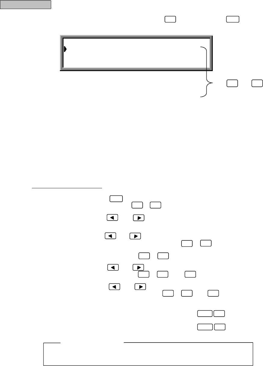
ALL SHIPS CALL
Category :DISTRESS
Telecommand-1 :DISTRESS RELAY
Dist−address :XXXXXXXXX
Nature :UNDESIGNATED DIST
Dist-position :12 ゚34’N123 ゚45’E
Dist-UTC :01:20
Dist-telecomm :J3E TEL
Call TX/RX freq: 4,208.0 / 4,208.0 kHz
Use and to
scroll the screen.
Procedure
Example: Procedure for a distress relay call to all ships
1. From the "MENU#1-EDIT&CALL" screen, press , and then press .
The "ALL SHIPS CALL" screen is displayed.
The following items have been set in this example.
「Category」:DISTRESS
「Telecommand-1」:DISTRESS RELAY
「Dist-address」:XXXXXXXXX
「Nature」:UNDESIGNATED DIST
「Dist-position」:12 ゚34’N123 ゚45’E
「Dist-UTC」:01:20
「Dist-telecomm」:J3E TEL
「Call TX/RX freq」:4,208.0 / 4,208.0 kHz
●Entering the respective items:
After selecting each item, press to confirm the selection.
(1) Dist-address: Use the numerical keys ( to ) to enter the address of the receiving
station (ship or coastal station).
(2) Category
Telecommand-1: Use the and keys to select the items.
Nature
Dist-telecomm
(3) Dist-position: Use the and keys to select the bearing, and then input the value
using the numerical keys ( to ).
(4) Dist-UTC: Use the numerical keys ( to ) to enter the time.
(5) Call TX/RX freq: Use the and keys to select one of the preset frequencies.
Alternatively, use the numerical keys ( to , and ) to directly
specify a frequency.
Set the "Work TX/RX freq" to a frequency in the same band as the "Call TX/RX freq".
6ENT
0 9 .
ENT
0 9
09
09
▲
▼
Note
3-50
2. Press , then open the cover on the left and press for at least 3
seconds (until the intermittent alarm tone changes to a continuous tone).
The following screen is displayed and the set distress message is transmitted.
When the transmission is completed, the following screen is displayed and the message is automatically
saved. After a brief interval, operation returns to the "MENU#1-EDIT&CALL" screen.
See (1), "Individual Call" for how to send a general message.
To store a message without sending it, press (SAVE).
To discard the message and quit without sending it, press (QUIT).
CALL
ALL SHIPS CALL Transmitting
TX frequency: 4,208.0 kHz
TX date&time:06.Sep.2001(Thu) 01:26
DISTRESS
ALL SHIPS CALL Send Completed
TX frequency : 4,208.0 kHz
TX date&time :06.Sep.2001(Thu) 01:26
FUNC 9
FUNC 4
Note
3-51
(7) GROUP CALL
This process is used to edit and transmit a message to a specific group.
FORMAT
FORMATFORMAT
FORMAT
GROUP
GROUP ADDRESS
GROUP ADDRESSGROUP ADDRESS
GROUP ADDRESS
XXXXXXXXX
CATEGORY
CATEGORYCATEGORY
CATEGORY
SHIP'S POTISION
SHIP'S POTISIONSHIP'S POTISION
SHIP'S POTISION
12°34'N123°45'E
WORK TX/RX FREQ
WORK TX/RX FREQWORK TX/RX FREQ
WORK TX/RX FREQ
12345.6/12346.5
CALL TX/RX FREQ
CALL TX/RX FREQCALL TX/RX FREQ
CALL TX/RX FREQ
4208.0/4219.5
EOS
EOSEOS
EOS
EOS
TELECOMMAND-1
TELECOMMAND-1TELECOMMAND-1
TELECOMMAND-1
J3E TEL
F1B/J2B FEC TTY
F1B/J2B ARQ TTY
F1B/J2B REC TTY
F1B/J2B TTY
A1A MORSE RECORD
SHIP'S POSITION
A1A MORSE KEY
F1C/F2C/F3C FAX
NO INFORMATION
F3E/G3E SIMP TEL
F3E/G3E DUP TEL
POLLING
UNCOMPLY
TELECOMMAND-2
TELECOMMAND-2TELECOMMAND-2
TELECOMMAND-2
NO INFORMATION
RES18 SHIP/AIR
MEDICALTRANS
PUB CALL OFFICE
TELECOMMAND-2
TELECOMMAND-2TELECOMMAND-2
TELECOMMAND-2
NO INFORMATION
ITU-T V.21
ITU-T V.22
ITU-T V.22 BIS
ITU-T V.23
ITU-T V.26 BIS
ITU-T V.26 TER
ITU-T V.27 TER
ITU-T V.32
TELECOMMAND-2
TELECOMMAND-2TELECOMMAND-2
TELECOMMAND-2
NO REASON
CONGESTION
BUSY
QUEUE
STATION BARRED
NO OPERATOR
NO
-
OPR
TEMPORALITY
EQUIP DISABLED
UNUSABLE FREQ
UNUSABLE MODE
TELECOMMAND-1
TELECOMMAND-1TELECOMMAND-1
TELECOMMAND-1
DATA MODEM
TELECOMMAND-2
TELECOMMAND-2TELECOMMAND-2
TELECOMMAND-2
TELECOMMAND-1
TELECOMMAND-1TELECOMMAND-1
TELECOMMAND-1
URGENCY
SAFETY
SHIP'S BUSINESS
ROUTINE
DISTRESS
3-52
GROUP CALL
Group address :XXXXXXXXX
Category :ROUTINE
Telecommand-1 :J3E TEL
Telecommand-2 :NO INFORMATION
Work TX/RX freq: 4,444.1/4,455.5 kHz
Call TX/RX freq: 4,208.0/4,219.5 kHz
Use and to
scroll the screen.
Procedure
1. From the "MENU#1-EDIT&CALL" screen, press , and then press .
The "GROUP CALL" screen is displayed.
The following items have been set in this example.
「Group address」:XXXXXXXXX
「Category」:ROUTINE
「Telecommand-1」:J3E TEL
「Telecommand-2」:NO INFORMATION
「Work TX/RX freq」:4,444.1/4,455.5 kHz
「Call TX/RX freq」:4,208.0/4,219.5 kHz
●Entering the respective items:
After selecting each item, press to confirm the selection.
(1) Group address: Use the numerical keys ( to ) to enter the address of the receiving
station (ship or coastal station).
(2) Category
Telecommand-1: Use the and keys to select the items.
Telecommand-2
(3) Work TX/RX freq Use the numerical keys ( to , and ) to directly specify a
frequency.
(4) Call TX/RX freq: Use the and keys to select one of the preset frequencies.
Alternatively, use the numerical keys ( to , and ) to directly
specify a frequency.
(5) Other settings:
・”Ship's position”: Use the and keys to select the bearing, and then input the
value using the numerical keys ( to ).
・Switching from "Ship's position" to "Work TX/RX freq": Press (FREQ).
・Switching from "Work TX/RX freq" to "Ship's position": Press (POS).
Set the "Work TX/RX freq" to a frequency in the same band as "Call TX/RX freq".
7ENT
0 9
09
0 9 .
FUNC 6
FUNC 5
ENT
▲
▼
0 9 .
Note
3-53
2. Press .
The following screen is displayed and the message is transmitted.
If the tuner is not tuned to the transmission frequency, the "tuner mismatch!!" warning message is
displayed. Press to tune the tuner, then transmit the message.
When the transmission is completed, the following screen is displayed. After a brief interval, operation
returns to the "MENU#1-EDIT&CALL" screen.
To discard the message and quit without sending it, press (QUIT).
To store a message without sending it, press (SAVE).
CALL
GROUP CALL Transmitting
TX frequency : 4,208.0 kHz
TX date&time :06.Sep.2001(Thu) 01:30
GROUP CALL Send Completed
TX frequency : 4,208.0 kHz
TX date&time :06.Sep.2001(Thu) 01:30
FUNC 9
ENT
FUNC 4
Note
Note
3-54
(8) AREA CALL
This procedure is used to edit and transmit a call message to ships in the specified area.
FORMAT
FORMATFORMAT
FORMAT
AREA
GEOGRAPHIC AREA
GEOGRAPHIC AREAGEOGRAPHIC AREA
GEOGRAPHIC AREA
N12E123DA10DO50
CATEGORY
CATEGORYCATEGORY
CATEGORY
SHIP'S POTISION
SHIP'S POTISIONSHIP'S POTISION
SHIP'S POTISION
12°34'N123°45'E
WORK TX/RX FREQ
WORK TX/RX FREQWORK TX/RX FREQ
WORK TX/RX FREQ
12345.6/12346.5
CALL TX/RX FREQ
CALL TX/RX FREQCALL TX/RX FREQ
CALL TX/RX FREQ
4208.0/4219.5
EOS
EOSEOS
EOS
EOS
TELECOMMAND-1
TELECOMMAND-1TELECOMMAND-1
TELECOMMAND-1
J3E TEL
F1B/J2B FEC TTY
F1B/J2B ARQ TTY
F1B/J2B REC TTY
F1B/J2B TTY
A1A MORSE RECORD
SHIP'S POSITION
A1A MORSE KEY
F1C/F2C/F3C FAX
NO INFORMATION
F3E/G3E SIMP TEL
F3E/G3E DUP TEL
POLLING
UNCOMPLY
TELECOMMAND-2
TELECOMMAND-2TELECOMMAND-2
TELECOMMAND-2
NO INFORMATION
RES18 SHIP/AIR
MEDICALTRANS
PUB CALL OFFICE
TELECOMMAND-2
TELECOMMAND-2TELECOMMAND-2
TELECOMMAND-2
NO INFORMATION
ITU-T V.21
ITU-T V.22
ITU-T V.22 BIS
ITU-T V.23
ITU-T V.26 BIS
ITU-T V.26 TER
ITU-T V.27 TER
ITU-T V.32
TELECOMMAND-2
TELECOMMAND-2TELECOMMAND-2
TELECOMMAND-2
NO REASON
CONGESTION
BUSY
QUEUE
STATION BARRED
NO OPERATOR
NO
-
OPR
TEMPORALITY
EQUIP DISABLED
UNUSABLE FREQ
UNUSABLE MODE
TELECOMMAND-1
TELECOMMAND-1TELECOMMAND-1
TELECOMMAND-1
DATA MODEM
TELECOMMAND-2
TELECOMMAND-2TELECOMMAND-2
TELECOMMAND-2
TELECOMMAND-1
TELECOMMAND-1TELECOMMAND-1
TELECOMMAND-1
URGENCY
SAFETY
SHIP'S BUSINESS
ROUTINE
DISTRESS
3-55
Use and to
scroll the screen.
●Area call setting
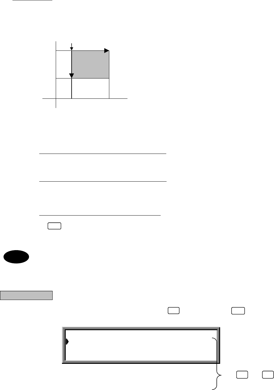
An area call is received by all ships navigating in a designated geographical area. For the area of called
stations (PARTY AD), latitude, longitude, deviation latitude (from North to South), and deviation longitude
(from West to East) are necessary. The area of the shaded part is designated in the figure below.
N
Reference point
20°
Deviation latitude (DLAT)=10°
10°
W E
120° 170°
S Deviation longitude (LONG)=50°
First, select the direction from N.E. (North-East), N.W. (North-West), S.E. (South-East), and S.W. (South-
West). In this example, the direction is N.E.
PARTY AD :N E DLAT LONG /
Next, enter 20°, 120°, making this latitude 20° and longitude 120°.
PARTY AD :N20E120 DLAT LONG /
In addition, as the deviation latitude (DLAT) and deviation longitude (LONG) are, respectively, 10° and 50°,
input 1050..
PARTY AD :N20E120DLAT10LONG50
Finally, press to confirm the area.
Up to 99° can be input for deviation latitude and deviation longitude.
Ranges that include the Arctic Pole or Antarctic Pole cannot be specified.
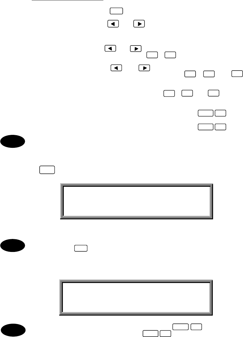
Procedure
1. From the "MENU#1-EDIT&CALL" screen, press , and then press .
The "AREA CALL" screen is displayed.
ENT
AREA CALL Transmissible
Area :N20E120DLAT10LONG50
Category :ROUTINE
Telecommand-1 :J3E TEL
Telecommand-2 :NO INFORMATION
Work TX/RX freq : 4,444.1/4,455.5 kHz
Call TX/RX freq : 4,208.0/4,219.5 kHz
8ENT
▲
▼
Note
3-56
The following items have been set in this example.
「Area」:N20E120DLAT10LONG50
「Category」:ROUTINE
「Telecommand-1」:
J3E TEL
「Telecommand-2」:NO INFORMATION
「Work TX/RX freq」:4,444.1/4,455.5 kHz
「Call TX/RX freq」:4,208.0/4,219.5 kHz
●Entering the respective items:
After selecting each item, press to confirm the selection.
(1) Category
Telecommand-1: Use the and keys to select the items.
Telecommand-2
(2) Area
Ship's position: Use the and keys to select the bearing, and then input the value
using the numerical keys ( to ).
(3) Call TX/RX freq: Use the and keys to select one of the preset frequencies.
Alternatively, use the numerical keys ( to , and ) to directly
specify a frequency.
(4) Other settings:
・"Work TX/RX freq": Use the numerical keys ( to , and ) to directly specify a
frequency.
・Switching from "Ship's position" to "Work TX/RX freq": Press (FREQ).
・Switching from "Work TX/RX freq" to "Ship's position": Press (POS).
Set the "Work TX/RX freq" to a frequency in the same band as "Call TX/RX freq".
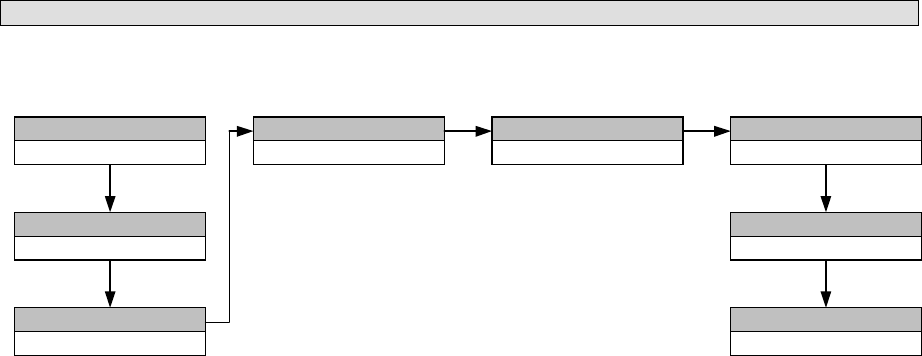
2. Press .
The following screen is displayed and the message is transmitted.
If the tuner is not tuned to the transmission frequency, the "tuner mismatch!!" warning message is
displayed. Press to tune the tuner, then transmit the message.
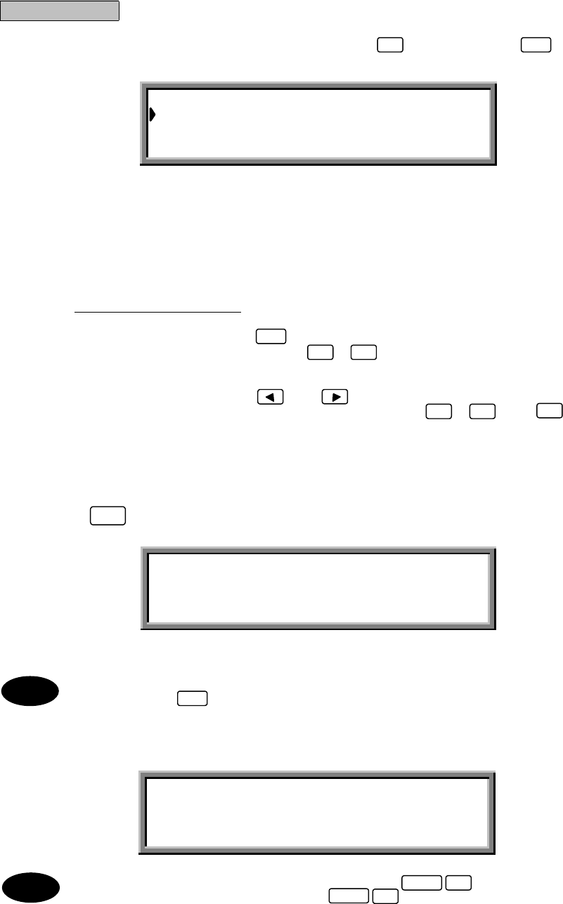
When the transmission is completed, the following screen is displayed. After a brief interval, operation
returns to the "MENU#1-EDIT&CALL" screen.
To discard the message and quit without sending it, press (QUIT).
To store a message without sending it, press (SAVE).
0 9
0 9 .
FUNC 6
FUNC 5
ENT
CALL
AREA CALL Transmitting
TX frequency : 4,208.0 kHz
TX date&time :06.Sep.2001(Thu) 01:30
AREA CALL Send Completed
TX frequency : 4,208.0 kHz
TX date&time :06.Sep.2001(Thu) 01:30
FUNC 9
ENT
FUNC 4
09.
Note
Note
Note
3-57
(9) POSITION REQUEST CALL
This feature is used when a coastal station wants to know a ship's position, or two ships want to know each other's
position.
FORMAT
FORMATFORMAT
FORMAT
INDIVIDUAL
ADDRESS
ADDRESSADDRESS
ADDRESS
XXXXXXXXX
CATEGORY
CATEGORYCATEGORY
CATEGORY
ROUTINE
TELECOMMAND-1
TELECOMMAND-1TELECOMMAND-1
TELECOMMAND-1
SHIP'S POSITION TELECOMMAND-2
TELECOMMAND-2TELECOMMAND-2
TELECOMMAND-2
NO INFORMATION FREQ/POTISION
FREQ/POTISIONFREQ/POTISION
FREQ/POTISION
NONE/NONE
CALL TX/RX FREQ
CALL TX/RX FREQCALL TX/RX FREQ
CALL TX/RX FREQ
4208.0/4219.5
EOS
EOSEOS
EOS
ACK RQ
[Fixed]
[Fixed] [Fixed]
[Fixed]
3-58
Procedure
1. From the "MENU#1-EDIT&CALL" screen, press , and then press .
The "POSITION REQUEST" screen is displayed.
The following items have been set in this example.
「Address」:XXXXXXXXX
「Call TX/RX freq」:4,208.0/4,219.5 kHz
●Entering the respective items:
After selecting each item, press to confirm the selection.
(1) Address: Use the numerical keys ( to ) to enter the address of the receiving station
(ship or coastal station).
(2) Call TX/RX freq: Use the and keys to select one of the preset frequencies.
Alternatively, use the numerical keys ( to , and ) to directly
specify a frequency.
2. Press .
The following screen is displayed and the message is transmitted.
If the tuner is not tuned to the transmission frequency, the "tuner mismatch!!" warning message is
displayed. Press to tune the tuner, then transmit the message.
When the transmission is completed, the following screen is displayed. After a brief interval, operation
returns to the "MENU#1-EDIT&CALL" screen.
To discard the message and quit without sending it, press (QUIT).
To store a message without sending it, press (SAVE).
POSITION REQUEST
Address :XXXXXXXXX
Call TX/RX freq : 4,208.0/4,219.5 kHz
9ENT
0 9 .
ENT
0 9
CALL
POSITION REQUEST Transmitting
TX frequency : 4,208.0 kHz
TX date&time :06.Sep.2001(Thu) 01:30
POSITION REQUEST Send Completed
TX frequency : 4,208.0 kHz
TX date&time :06.Sep.2001(Thu) 01:30
FUNC 9
ENT
FUNC 4
Note
Note
3-59
(10) POLLING CALL
This feature is used to confirm that the destination station exists within a communication area.
FORMAT
FORMATFORMAT
FORMAT
INDIVIDUAL
ADDRESS
ADDRESSADDRESS
ADDRESS
XXXXXXXXX
CATEGORY
CATEGORYCATEGORY
CATEGORY
ROUTINE
TELECOMMAND-1
TELECOMMAND-1TELECOMMAND-1
TELECOMMAND-1
POLLING TELECOMMAND-2
TELECOMMAND-2TELECOMMAND-2
TELECOMMAND-2
NO INFORMATION FREQ/POTISION
FREQ/POTISIONFREQ/POTISION
FREQ/POTISION
NONE/NONE
CALL TX/RX FREQ
CALL TX/RX FREQCALL TX/RX FREQ
CALL TX/RX FREQ
4208.0/4219.5
EOS
EOSEOS
EOS
ACK RQ
[Fixed]
[Fixed] [Fixed]
[Fixed]
3-60
Procedure
1. From the "MENU#1-EDIT&CALL" screen, press , and then press .
The "POLLING CALL" screen is displayed.
The following items have been set in this example.
「Address」:XXXXXXXXX
「Call TX/RX freq」:4,208.0/4,219.5 kHz
●Entering the respective items:
After selecting each item, press to confirm the selection.
(1) Adress: Use the numerical keys ( to ) to enter the address of the receiving station
(ship or coastal station).
(2) Call TX/RX freq: Use the and keys to select one of the present frequencies.
Alternatively, use the numerical keys ( to ,and ) to directly
Specify a frequency.
2. Press .
The following screen is displayed and the message is transmitted.
If the tuner is not tuned to the transmission frequency, the "tuner mismatch!!" warning message is
displayed. Press to tune the tuner, then transmit the message.
When the transmission is completed, the following screen is displayed. After a brief interval, operation
returns to the "MENU#1-EDIT&CALL" screen.
To discard the message and quit without sending it, press (QUIT).
To store a message without sending it, press (SAVE).
POLLING CALL
Address :XXXXXXXXX
Call TX/RX freq: 4,208.0/4,219.5 kHz
1ENT
0
CALL
POLLING CALL Transmitting
TX frequency : 4,208.0 kHz
TX date&time :06.Sep.2001(Thu) 01:30
POLLING CALL Send Completed
TX frequency : 4,208.0 kHz
TX date&time :06.Sep.2001(Thu) 01:30
FUNC 9
ENT
FUNC 4
Note
Note
0 9 .
ENT
0 9
3-61
(11) TEST CALL
If possible, refrain from making tests using any of the frequencies listed in Section 8.2.1. However, should such a
test become unavoidable, first obtain permission from the targeted coastal station.
FORMAT
FORMATFORMAT
FORMAT
INDIVIDUAL
ADDRESS
ADDRESSADDRESS
ADDRESS
XXXXXXXXX
CATEGORY
CATEGORYCATEGORY
CATEGORY
SAFETY
TELECOMMAND-1
TELECOMMAND-1TELECOMMAND-1
TELECOMMAND-1
TEST TELECOMMAND-2
TELECOMMAND-2TELECOMMAND-2
TELECOMMAND-2
NO INFORMATION FREQ/POTISION
FREQ/POTISIONFREQ/POTISION
FREQ/POTISION
NONE/NONE
CALL TX/RX FREQ
CALL TX/RX FREQCALL TX/RX FREQ
CALL TX/RX FREQ
4208.0/4219.5
EOS
EOSEOS
EOS
ACK RQ
[Fixed] [Fixed] [Fixed]
3-62
Procedure
1. From the "MENU#1-EDIT&CALL" screen, press , and then press .
The "TEST CALL" screen is displayed.
The following items have been set in this example.
「Address」:XXXXXXXXX
「Call TX/RX freq」:4,208.0/4,219.5 kHz
2. Press .
The following screen is displayed and the message is transmitted.
If the tuner is not tuned to the transmission frequency, the "tuner mismatch!!" warning message is
displayed. Press to tune the tuner, then transmit the message.
When the transmission is completed, the following screen is displayed. After a brief interval, operation
returns to the "MENU#1-EDIT&CALL" screen.
To discard the message and quit without sending it, press (QUIT).
To store a message without sending it, press (SAVE).
Normally, the message content is predetermined so that the message is sent to a coastal station.
TEST CALL Transmissible
Address :XXXXXXXXX
Call TX/RX freq: 4,208.0/4,219.5 kHz
1ENT
1
CALL
TEST CALL Transmitting
TX frequency : 4,208.0 kHz
TX date&time :06.Sep.2001(Thu) 01:30
ENT
TEST CALL Send Completed
TX frequency : 4,208.0 kHz
TX date&time :06.Sep.2001(Thu) 01:30
FUNC 9
FUNC 4
Note
Note
3-63
3.5.4 Other Functions
(1) Frequency scanning
When the JSB-196/196GM Radiotelephone is connected, scanning*1 reception among the six specified
frequencies is available. When the NCT-196N automatic acknowledgement setting*2 is ON and a message
requiring acknowledgment is received*3, the acknowledgement message is transmitted on a transmit frequency
that is paired with the reception frequency.
This section describes how to set up the scanning function.
*1:The selected reception frequency (scanning frequency) is switched at intervals of about 0.3 sec.
*2:See "● AUTO ACKNOWLEDGEMENT SETUP" in Section 3.5.4 (4), "Other Settings."
*3:Indicates that the "EOS" of the message compiled in steps (1) to (11) of Section 3.5.3, "Transmitting Messages" is set to
ACK RQ (acknowledgement required).
● Starting and stopping scanning
The scanning frequency must be specified before starting or stopping scanning. Refer to "Specifying the scanning
frequency" below.
Procedure
1. Press , and then (SCAN).
Scanning starts for the specified frequencies.
2. Press , and then (SCAN).
Scanning stops.
● Specifying the scanning frequency
Procedure
1. Check that the "DSC watching" screen is displayed.
If the "DSC watching" screen is not displayed, press 3 times in succession to switch to the
"DSC watching" screen.
When the mark is displayed on the screen, no printer is connected to the NCT-196.
1
FUNC
1
FUNC
DSC watching 06.Sep.2001(Thu) 01:26
99゚99’N999゚99’E SPEED:__._KT at 88:88
Self-ID = XXXXXXXXX [UTC]
STOP
P
Note
3-64
MENU #2−READOUT&SETUP Select no.
1.Received distress message readout
2.Received others message readout
3.Setup
4.Self test
SETUP Select no.
1. Date&time edit
2. Position edit
3. Calling frequency registration
4. Address registration
5. Distress setup
6. Others alarm setup
7. Automatic acknowledgement setup
8. Scanning setup
9. Watchkeeping receiver setup
Use and to
scroll the screen.
Use and to
scroll the screen.
2. Press .
The "MENU#1-EDIT&CALL" screen is displayed.
3. Press again.
The "MENU#2-READOUT&SETUP" screen is displayed.
4. Press , and then press .
The "SETUP" screen is displayed.
MENU
MENU #1 −EDIT&CALL Select no.
1. Individual call
2. Acknowledgement call
3. Distress call
4. Distress relay call
5. Auto / semi−auto call
6. All ships call Use and to scroll the screen.
7. Group call
8. Area call
9. Position request
10. Polling call
11. Test call
▲
▼
MENU
3ENT
▲
▼
▲
▼
3-65
SCANNING SETUP
[1] 1,610.0 / 1,615.0 kHz
[2] 2,000.0 / 2,000.0 kHz
[3] 3,000.0 / 3,000.0 kHz
[4] 4,208.0 / 4,219.0 kHz
[5] 5,000.0 / 5,000.0 kHz
[6] 6,000.0 / 6,000.0 kHz
TX RX
Use and to
scroll the screen.
5. Press , and then press .
The "SCANNING SETUP " screen is displayed.
6. Enter the "Transmit frequency/Receive frequency" pair for each channel.
Press and then to cancel a setting and leave it blank.
7.On completion of entering the data, press , and then press (SAVE).
Press to tune the tuner and then return to the "SETUP" screen.
Press to abort tuning and return to the "SETUP" screen.
Press , and then press (QUIT) to cancel this menu.
8ENT
ENTCLR
Tune regist frequency?
[ENT] key :TUNE
[STOP] key:NO TUNE
9
FUNC
ENT
STOP
FUNC 4
▲
▼
Note
Note
3-66
SETUP Select no.
1. Date&time edit
2. Position edit
3. Calling frequency registration
4. Address registration
5. Distress setup
6. Others alarm setup
7. Automatic acknowledgement setup
8. Scanning setup
9. Watchkeeping receiver setup
CALLING FREQUENCY REGISTRATION (TX/RX)
[1] 12,345.6/12,356.7 kHz ( )
[2] NONE / NONE kHz ( )
[3] NONE / NONE kHz ( )
[4] NONE / NONE kHz ( )
[5] NONE / NONE kHz ( )
[6] NONE / NONE kHz ( )
Use and to
scroll the screen.
Use and to
scroll the screen.
(2) Useful Functions
The NCT-196N register up to six party addresses with a shorthand name, and up to six calling frequencies.
The registered contents are retrieved by using and when compiling a call message, obviating the need to
enter numbers.
The addresses and calling frequencies are stored from the "SETUP" screen. See steps 1 to 3 of (1) Specifying the
scanning frequency" for how to display the "SETUP" screen.
● Registering a calling frequency
Procedure
1. From the "SETUP" screen, press , and then press .
The "CALLING FREQUENCY REGISTRATION (TX/RX)" screen is displayed.
2. Enter the "Transmit frequency/Receive frequency (name)" for each channel.
・Enter the transmit frequency/receive frequency pair using to and .
・Enter (name) as follows: 1. Selecting characters: Use and to select characters inside the
parentheses ().
2. Confirming characters: After selecting each character, press .
To go to the next channel or skip to the next channel without specifying a name, press two times.
3. On completion of entering the data, press , and then press (SAVE).
Press to tune the tuner and then return to the "SETUP" screen.
Press to abort tuning and return to the "SETUP" screen.
Press to delete registered calling frequency.
Press , and then press (QUIT) to cancel this menu.
3ENT
0 9 .
ENT
ENT
Tune regist frequency?
[ENT] key : TUNE
[STOP] key: NO TUNE
9
FUNC
ENT
STOP
▲
▼
▲
▼
FUNC 4
Note
CLR
Note
3-67
ADDRESS REGISTRATION
[1] _ ( )
[2] ( )
[3] ( )
[4] ( )
[5] ( )
[6] ( )
Use and to
scroll the screen.
● Registering an address
Procedure
1. From the "SETUP" screen, press , and then press .
The "ADDRESS REGISTRATION" screen is displayed.
2. Enter the address (name) for each channel.
・Enter the address using to and .
・Enter (name) as follows: 1. Selecting characters: Use and to select characters inside the
parentheses ().
2. Confirming characters: After selecting each character, press .
To go to the next channel or skip to the next channel without specifying a name, press two times.
3. On completion of entering the data, press , and then press (SAVE).
Press to delete registered address.
Press , and then press (QUIT) to cancel this menu.
4ENT
0 9 .
ENT
ENT
9
FUNC
▲
▼
FUNC 4
Note
CLR
Note
3-68
PRINT MENU
1.ALL RECEIVED DISTRESS MESSAGES
2.ALL RESEIVED OTHERS MESSAGES
3.ALL EDIT/CALL MESSAGES
4.ALL SETUP INFORMATION Use and to
scroll the screen.
(3) Printing function
When a printer is connected, all received messages are printed out upon reception. In addition, it is also possible to
print out other stored information.
The printing function enables the followings and the procedures are described in this section.
・The printing of all of the files, which classification is selected from the print menu.
・The printing of a selected file, which contents is displayed on screen.
● Printing from the print menu (batch printing of multiple files)
Procedure
1. Check that the "DSC watching" screen is displayed.
If the "DSC watching" screen is not displayed, press 3 times in succession to switch to the
"DSC watching" screen.
When the mark is displayed on the screen, no printer is connected to the NCT-196.
2. Press , and then (PRINT).
The "PRINT MENU" screen is displayed.
3. Select the item to be printed, and then press .
Printing starts.
4. When printing is finished, press , and then press (QUIT).
Operation returns to the "DSC watching" screen.
● Printing a specified file
Procedure
1. Press once or twice.
The "MENU#1-EDIT&CALL" screen or "MENU#2-READOUT&SETUP" screen is displayed.
2. Enter the number of the file to be printed, and then press .
The file content is displayed.
3. Press , and then press (PRINT).
The displayed file is printed.
4. When printing is finished, press , and then press (QUIT).
Operation returns to the"MENU#1-EDIT&CALL" screen or "MENU#2-READOUT&SETUP" screen.
DSC watching 06.Sep.2001(Thu) 01:26
12゚34’N123゚45’E SPEED:12.4KT at 01:26
Self-ID = XXXXXXXXX [UTC]
STOP
3
FUNC
ENT
FUNC 4
MENU
ENT
3
FUNC
FUNC 4
P
▲
▼
Note
3-69
SETUP Select no.
1. Date&time edit
2. Position edit
3. Calling frequency registration
4. Address registration
5. Distress setup
6. Others alarm setup
7. Automatic acknowledgement setup
8. Scanning setup
9. Watchkeeping receiver setup
Use and to
scroll the screen.
(4) Other settings
The following procedures are explained in this section:
・How to compile the message transmitted when pressing .
・ How to set the auto acknowledgement to ON/OFF for an acknowledgment required call
・ Other settings.
ATTENTION
Pay close attention when inputting and/or modifying the information described in this section as the contents
are critical for operating the DSC. If these operations are unclear, contact JRC or our agents.
The data is input using the "SETUP" screen. See the above-mentioned “Specifying the scanning frequency" 1-3
steps of “(1) Frequency scanning” for how to display the "SETUP" screen. However regarding the "DATE&TIME
EDIT" and "POSITION EDIT" settings in this setup menu, see Section 4.2 "Setting Position and Time Data".
DISTRESS
▲
▼
3-70
● DISTRESS SETUP
This function is used to compile a distress call message to be transmitted by pressing .
Nature : UNDESIGNATED DIS ←【FIXED】Nature of the distress (undesignated distress)
Position : 12 ゚34’N123 ゚45’E ←【AUTO or MANUAL】The navigation equipment data or manually
entered data.
Time : 19:00 ←【AUTO or MANUAL】The navigation equipment data or manually
entered data.
Telecommand : J3E TEL ←【VARIABLE】The data set using this menu.
Tx frequency : 2187.5kHz ←【VARIABLE】The data set using this menu.
"Telecommand" shows the follow-on communication mode with the RCC that received the distress message.
Normally, select either radiotelephone mode or MF/HF ARQ communication (F1B/J2B ARQ).
"Tx frequency" shows a transmission frequency for DSC distress message calls. When the radio equipment is set
to 2187.5 or 8414.5kHz, those frequencies take priority.
Procedure
1. From the "SETUP" screen, press and then press .
The "DISTRESS SETUP" screen is displayed.
2. Enter each item.
・Use and to change a setting and and to move the cursor and select the item.
・Press to confirm a setting.
・See Section 4.3.3 (3), "Distress Call" for items for which "Telecommand" can be selected.
3. On completion of entering the data, press , and then press (SAVE).
Operation returns to the "SETUP" screen.
Press , and then press (QUIT) to cancel this menu.
5ENT
DISTRESS SETUP
Dist-telecomm : J3E TEL
Dist-TX/RX freq: 2,187.5kHz
9
FUNC
▼
▲
ENT
DISTRESS
FUNC 4
Note
3-71
● OTHERS ALARM SETTING
This alarm can be set ON/OFF when receiving non-distress/non-urgency calls. Distress calls can be distinguished
from other calls by the difference in the beeping sounds. When receiving distress calls, the alarm always sounds;
the alarm for distress calls cannot be turned OFF.
Procedure
1. From the "SETUP" screen, press and then press .
The "OTHERS ALARM SETTING" screen is displayed.
2. Select "ON" or "OFF".
・The default setting is "ON". Use and to change the setting.
・Press to confirm the setting.
3. On completion of entering the data, press , and then press (SAVE).
Operation returns to the "SETUP" screen.
Press , and then press (QUIT) to cancel this menu.
6ENT
OTHERS ALARM SETUP
Alarm:ON
ENT
9
FUNC
FUNC 4
Note
3-72
● AUTOMATIC ACKNOWLEDGEMENT SETUP
The DSC terminal can be set to automatically send back an acknowledgement call (with ACK BQ for EOS) when
receiving a DSC call with ACK RQ for EOS. However, when the CATEGORY is DISTRESS, URGENCY, or
SAFETY, no acknowledgement is made automatically, even though ACK RQ is specified for EOS.
Acknowledgement is made manually for all distress calls.
Procedure
1. From the "SETUP" screen, press and then press .
The "AUTOMATIC ACKNOWLEDGEMENT SETUP" screen is displayed.
2. Select "ON" or "OFF".
・The default setting is "ON". Use and to change the setting.
・Press to confirm the setting.
3. On completion of entering the data, press , and then press (SAVE).
Operation returns to the "SETUP" screen.
Press , and then press (QUIT) to cancel this menu.
7ENT
AUTOMATIC ACKNOWLEDGEMENT SETUP
Acknowledgement:ON
ENT
9
FUNC
FUNC 4
Note
3-73
WATCHKEEPING RECEIVER SETUP
CH1. 2187.5kHz : ON(const)
CH2. 4207.5kHz : ON
CH3. 6312.0kHz : OFF
CH4. 8414.5kHz : ON(const)
CH5. 12577.0kHz : OFF
CH6. 16804.5kHz : ON
Use and to
scroll the screen.
● WATCHKEEPING RECEIVER SETUP
This procedure sets the Watch-keeping receiver's scanning frequency. The 2187.5kHz and 8414.5kHz frequencies
are preselected; here, frequencies are selected for the other four channels.
The "DISTRESS FREQUENCY" lamps (on the front panel) are turned ON/OFF for each set channel. The lamps for
2187.5kHz and 8414.5kHz are always ON.
Procedure
1. From the "SETUP" screen, press and then press .
The "WATCHKEEPING RECEIVER SETUP" screen is displayed.
2. Select "ON" or "OFF".
・The default setting is "ON". Use and to change the setting.
・Press to confirm the setting.
The corresponding lamp for that frequency is turned ON or OFF according to the setting.
3. On completion of entering the data, press , and then press (SAVE).
Operation returns to the "SETUP" screen.
Press , and then press (QUIT) to cancel this menu.
9ENT
ENT
9
FUNC
▲
▼
FUNC 4
Note
3-74
● CLICK SOUND SETTING
The click sound set to ON/OFF during turning on the NCT-196N.
Procedure
1. Press and .
When turning OFF the power switch, click sound is reset to ON.
● MODEM RESET
This operation is the same as the Power ON reset.
Procedure
1. Press and .
The following display appears.
2. The initialization is completed in several seconds.
The following initial display appears.
0
FUNC
FUNC STOP
JRC NCT-196N DSC/NBDP MODEM
Software Version MAIN:X.XX SUB:X.XX
Navigation :NMEA0183
Transceiver:JSB-196/196GM
Note
DSC watching 06.Sep.2001(Thu) 01:26
12゚34’N123゚45’E SPEED:12.4KT at 01:26
Self-ID = XXXXXXXXX [UTC]
3-75
3.6 NBDP operations
The NCT-196N DSC/NBDP MODEM has several communication methods in telex (TLX) mode as NBDP function.
Previously created message files or keyboard-typed messages can be sent during the communication. All of
operations are performed using NDZ-127J DTE, and the communication methods and other settings for TLX mode
are described in this chapter. (Regarding the MODE selection for TLX, see “4.3.2 MODE change to TLX”.)
3.6.1 NBDP Settings
Before operations in TLX mode, setup the NBDP functions using SYSTEM Î NBDP setup menu of the
NDZ-127J DTE. The following screen appeared by selecting the menu item.
Each parameter is set as follows:
ARQ/FEC 4- or 5-digit Self-ID : Fixed
GFEC 4- or 5-digit Self-ID : Fixed
ARQ/FEC 9-digit Self-ID : Fixed
GFEC 9-digit Self-ID : Fixed
Answerback : Fixed
Max. FEC error rate : Press Enter key and setup in the input window.
Max. automatic call series : Press Enter key and set a value of 1-99 in the input display.
Collective FEC receiving : Press Enter key to change ON/OFF.
Internal alarm : Press Enter key to change ON/OFF.
Time duration for AUTO : Press Enter key and setup the time in the input window.
Restart : Press Enter key to change ON/OFF.
Finite start/restart : Press Enter key to change ON/OFF.
Transmitter pre-key time : Press Enter key and setup the time in the input window.
After these settings, select the [Save] button or [Cancel] button to finish this setup.
The above parameters showed “Fixed” have already been set and are impossible to be changed.
The meanings of the above items are as follows;
・Max. FEC error rate :The limit value of error rate to continue to receive CFEC/
SFEC. When the error rate is beyond the value due to the
noisy radio circuit condition or any other signals, the
MODEM stops the receiving and return to stand-by.
・Max. automatic call series : The limit value of retrying the CALL mode sequence. The
interval to retry is 15 minutes respectively.
Note
ARQ/FEC 4- or 5-digit Self-ID : 54321 0000
GFEC 4- or 5-digit Self-ID : 11111 0000
ARQ/FEC 9-digit Self-ID : 987654321
GFEC 9-digit Self-ID : 222222222
Answerback : 54321 FFFFF X
Max. automatic call series : 1
Collective FEC receiving : ON
Internal alarm : ON
Time duration for AUTO/MRTX : 10 min.
Restart : ON
Finite start/restart : ON
[ Save ] [ Cancel ]
NBDP setup
Max. FEC error rate. : 30%
↓
3-76
・Collective FEC receiving : ON - CFEC receiving is permitted.
OFF - CFEC receiving is prohibited.
・Internal alarm : ON - Internal alarm works.
OFF - Internal alarm does not work.
・Time duration for AUTO : Time duration setting for AUTO mode
・Restart : ON - The MODEM tries to reconnect when the circuit
established once is lost for 32 times of
successive REPEAT condition
OFF - The MODEM returns to stand-by when the
circuit established once is lost for 32 times of
successive REPEAT condition
・
Finite start/restart : ON - The MODEM returns to stand-by when the
times of calling a partner station are reached to
128 in ARQ mode.
OFF - The MODEM continues to call a partner station
even if the times of calling are reached to 128
in ARQ mode.
・Transmitter pre-key time : Adjustment of timing from KEY ON to signal output for the
transmitter electrical specification. It is also available to
arrange the Send/Receive timing between long-ranged
partner station.
3-77
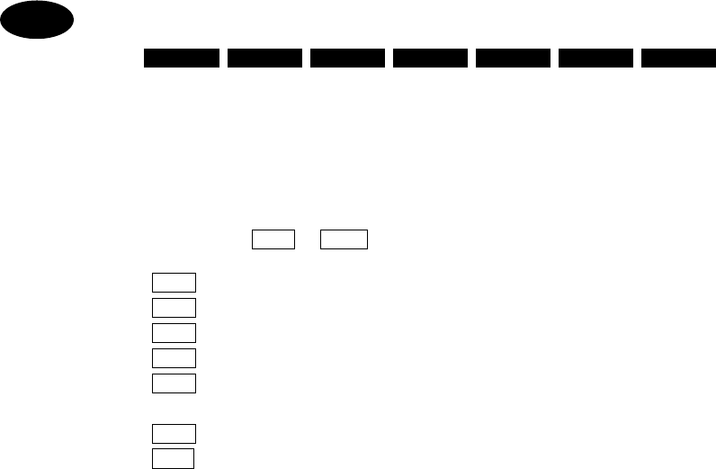
3.6.2 ARQ Communication
ARQ mode is two way telex communication with a partner as a destination station. When beginning to call a
partner using ARQ mode, it is necessary to select a partner (ID) and a communication channel. The operation from
the beginning until the end of the communication with a partner are described in this section.
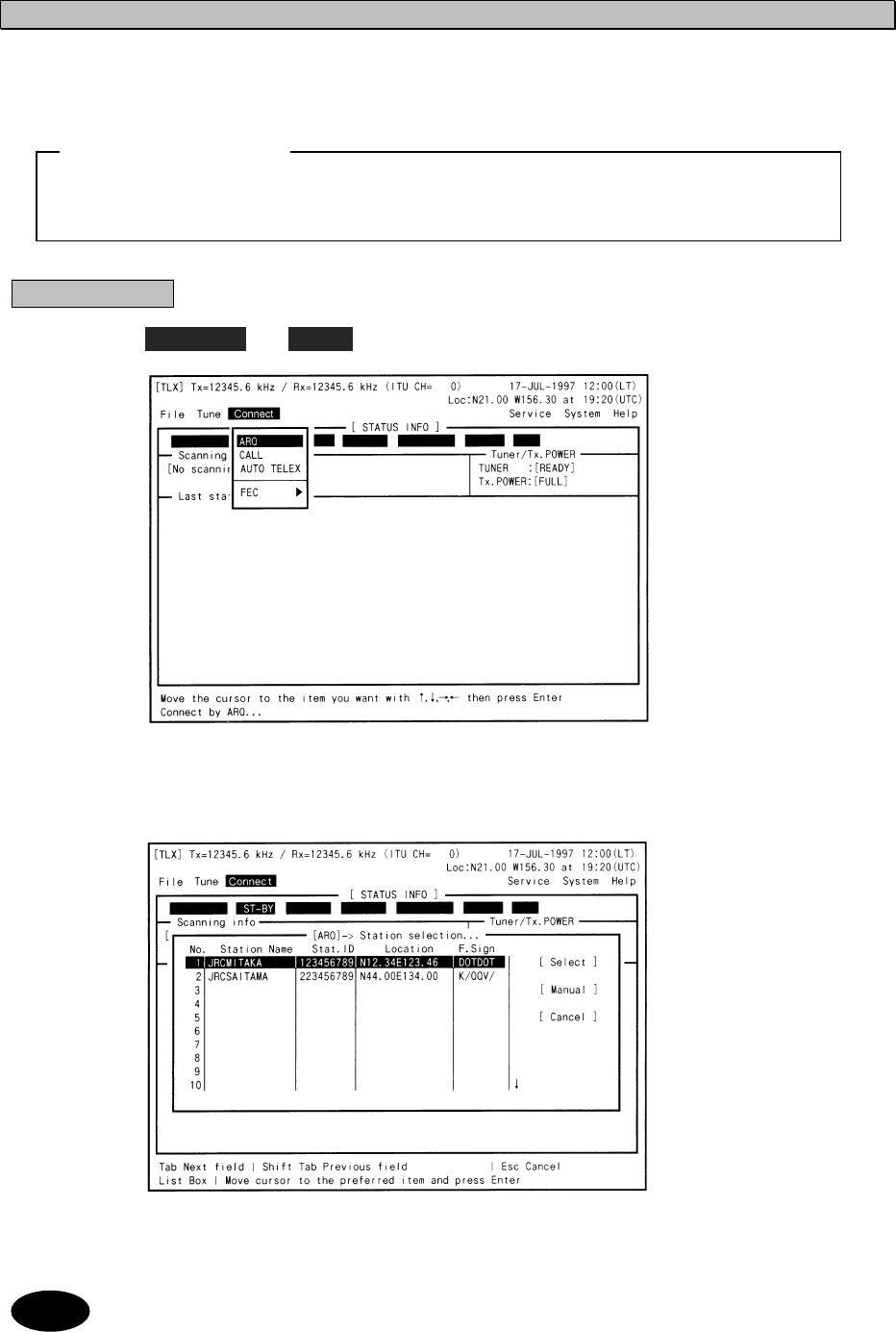
Procedure
1. Select Connect Î
ÎÎ
Î ARQ and press Enter key.
2. Select a partner station from the following window and press Enter key.
If [ Manual ] button is selected using Tab and Enter keys, the partner ID and Frequency/Channel can
be set manually.
・Before transmitting, confirm that the selected channel / frequency is not occupied by other station(s).
・Do not operate JSB-196 during ARQ communication.
ATTENTION
Note
3-78
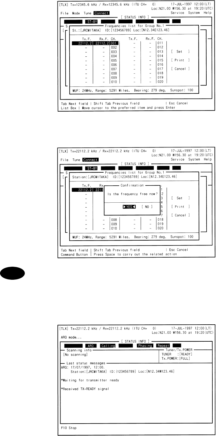
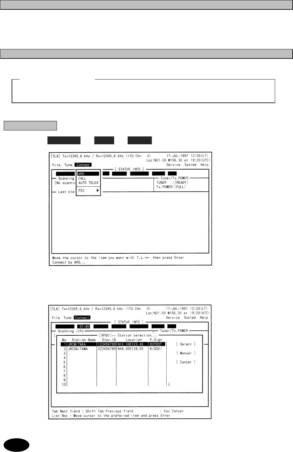
3. Select Tx/Rx frequency from the following window and press Enter key.
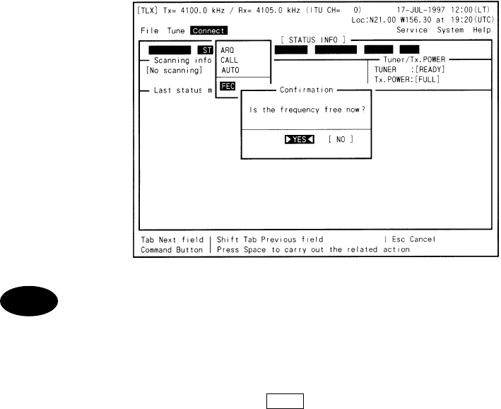
4. After the following window opened, check the channel condition and if not occupied,
press Enter key.
If the channel is occupied by the other stations, select [ NO ] and return to step 3 to select another
channel.
5. The channel is tuned automatically and the NCT-196N begins to call a partner
station.
The following screen is displayed while calling.
Note
3-79
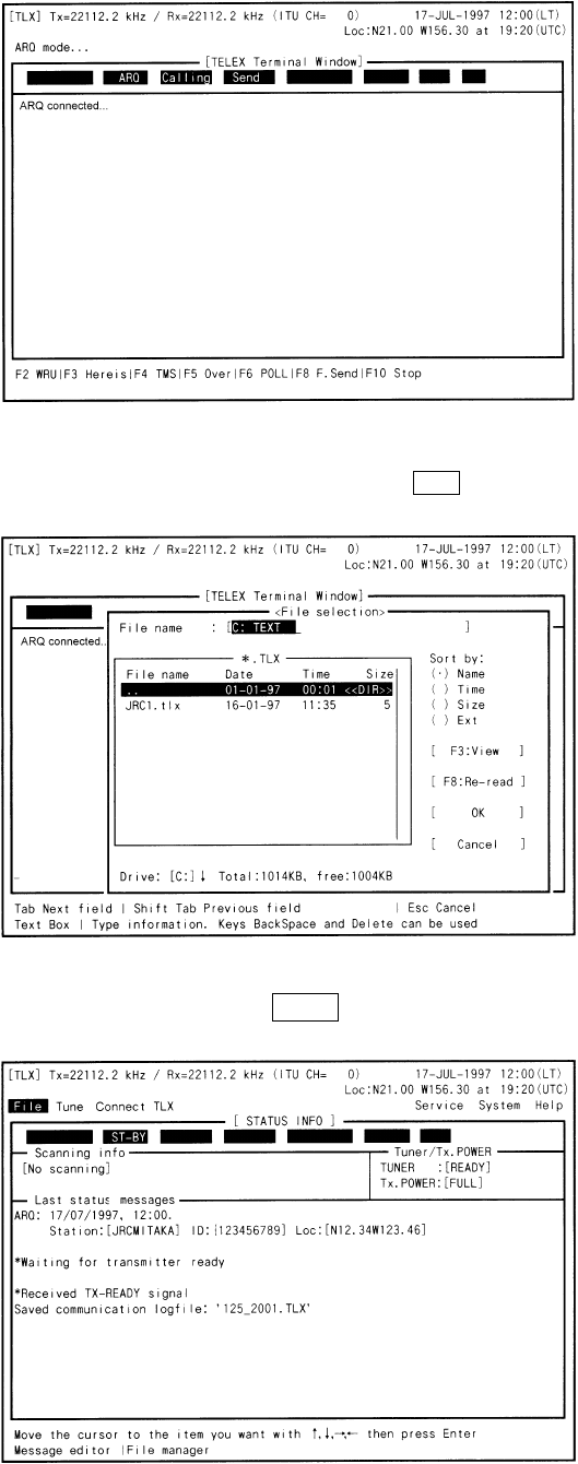
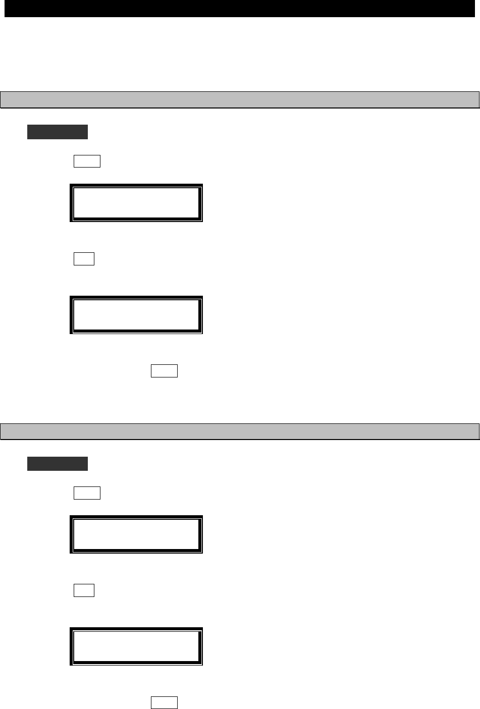
6. When the connection is established, the following screen appears and the DTE is
ready to communicate with a partner station.
Send message to the partner station using the keyboard.
In case of sending the previously created message file, press F8 (F.Send) and select the file to be sent
on the following window.
7. To terminate communication, press F10 .
The following display appears and the DTE returns to the stand-by.
3-80
・The meanings of cells showed in [ STATUS INFO ] are as follows;
(no use) (*1) (*2) (*3) (*4) (*5) (*6)
*1 : Communication mode (stand-by, ARQ, CFEC, SFEC)
*2 : The position related with a partner station (Calling - master, Called - slave)
*3 : The right to send message (Send - enable to send message, Receive - wait)
*4 : MODEM condition on connecting with a partner station (Phasing, Rephasing)
*5 : Communication data error condition (Repeat - resending data)
*6 : Communication condition (TRAF - sending data completed, RQ - repeating)
・The function key F 2 ~ F10 assignments are as follows;
F 2 : WRU - Request to send Answerback code of a partner station
F 3 : Here is - Sending Answerback code of own station
F 4 : TMS - Sending the time of own position
F 5 : Over - Exchanging the right to send message
F 6 : POLL - Getting the right to send messages without terminating the
communication even if a partner station try to terminate
F 8 : F.Send - Sending the previously created file
F10
: Stop - Terminating communication
Note
3-81
3.
3.6.3 FEC Communication
There are two types of FEC modes such as SFEC (Selective FEC) in which a destination is specified and CFEC
(Collective FEC) in which the destination is not specified. The ways to communicate using FEC modes are
described below. Note that the FEC receiving is automatic so the operation method is left out in this section, and
furthermore CFEC receiving can be disabled using NBDP setup. (See “6.1 NBDP settings.)
3.6.3.1 SFEC Communication
Procedure
1. Select Connect Î
ÎÎ
Î FEC Î
ÎÎ
Î SFEC and press Enter key.
2. Select a partner station from the following window and press Enter key.
If [ Manual ] button is selected using Tab and Enter keys, the partner ID and Frequency/Channel can
be set manually.
・Before transmitting, confirm that the selected channel / frequency is not occupied by other station(s).
ATTENTION
Note
3-82
3. Select Tx/Rx frequency from the following window and press Enter key.
4. After the following window opened, check the channel condition and if not occupied,
press Enter key.
If the channel is occupied by the other stations, select [ NO ] and return to step 3 to select another
channel.
5. The channel is tuned automatically and the NCT-196N begins to call a partner
station.
・
The communication is started after displayed “Message start…” on screen.
・
To terminate communication, press F10 .
Note
3-83
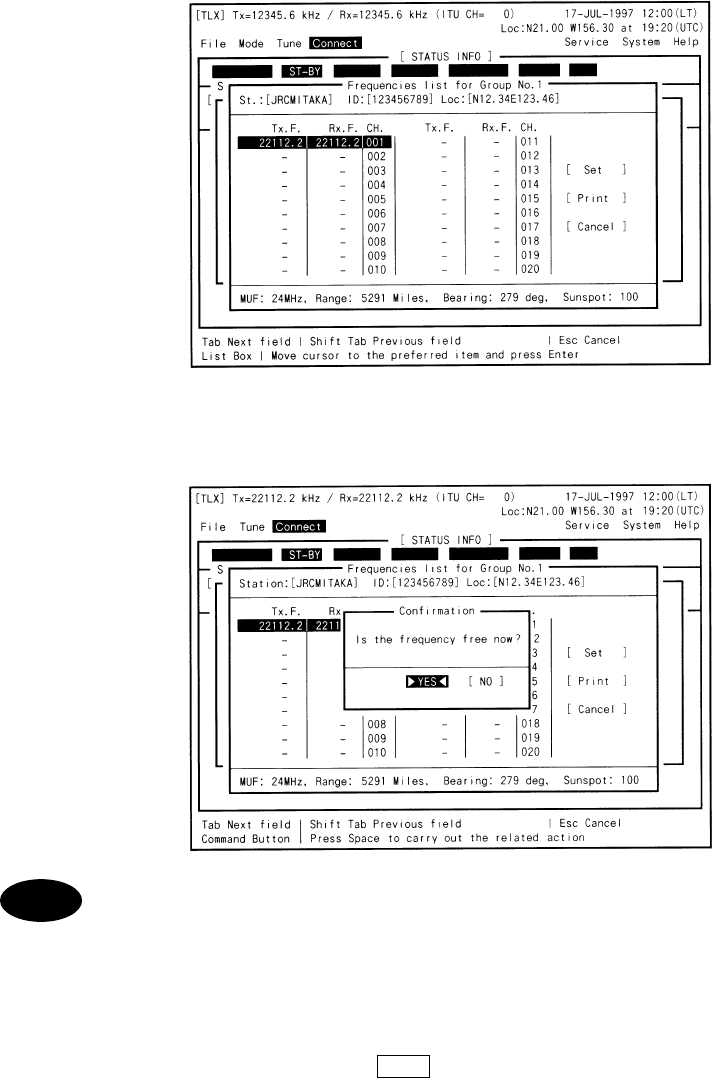
3.6.3.2 CFEC Communication
Procedure
1. Select Connect Î
ÎÎ
Î FEC Î
ÎÎ
Î CFEC and press Enter key.
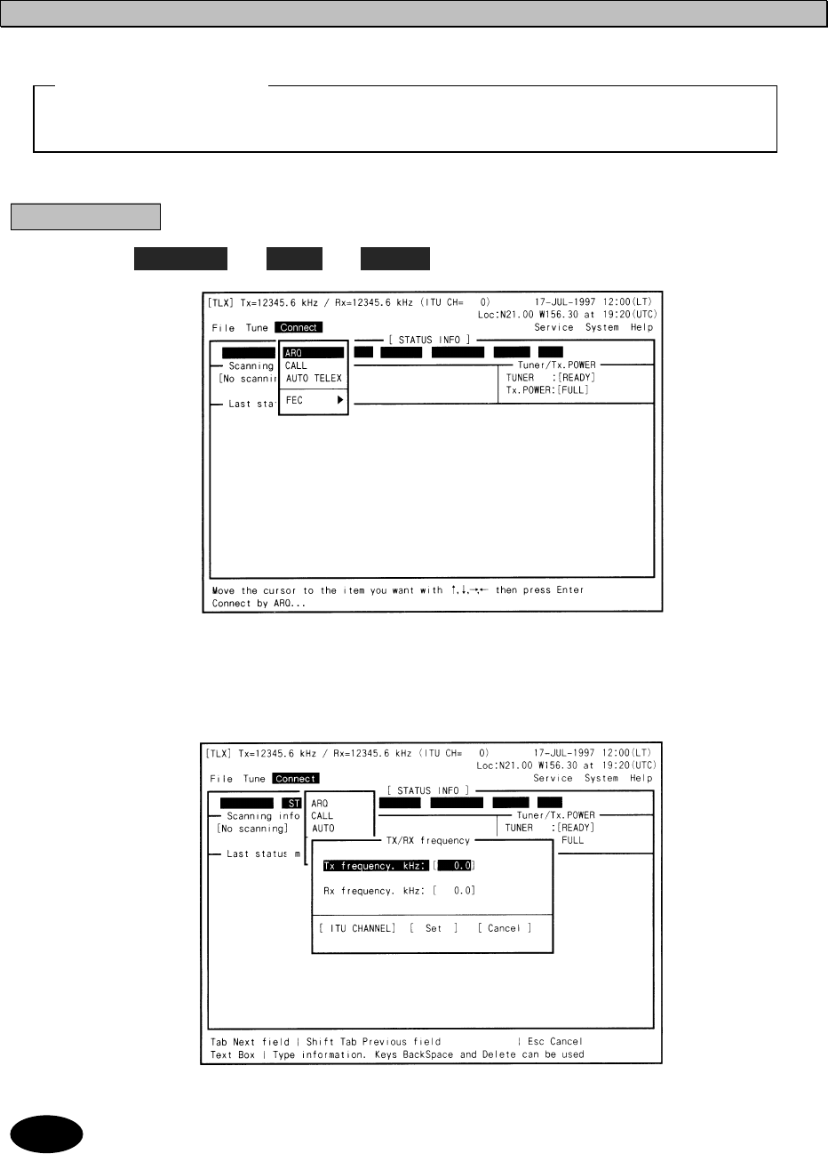
2. Input Tx/Rx frequency on the following window. Then select [ Set ] using Tab key and
press Enter key.
If input using ITU channel, select [ ITU CHANNEL ] button using Tab and Enter keys.
・Before transmitting, confirm that the selected channel / frequency is not occupied by other station(s).
ATTENTION
Note
3-84
3. After the following window opened, check the channel condition and if not occupied,
press Enter key.
If the frequency is occupied by the other stations, select [ NO ] and return to step 2 to select another
frequency.
4. The frequency is tuned automatically and the NCT-196N begins to call all ships.
・
The communication is started after displayed “Message start…” on screen.
・
To terminate communication, press F10 .
Note
3-85
3.
3.6.4 Scanning for TLX mode
The NBDP function of the NCT-196N can be set to scan a specified group channels so that the NCT-196N respond
to the station automatically if there is a station calling own station by ARQ or transmitting by FEC. The way to
start/stop the scanning is described in this section.
3.6.4.1 Scanning start
Procedure
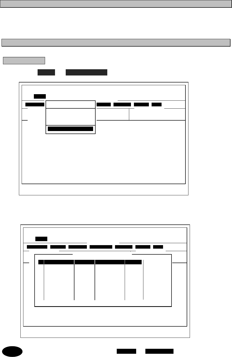
1. Select Tune Î
ÎÎ
Î Scanning start and press Enter key.
2. Select the desired station on the following window and press Enter key.
Scanning is started in order by the channel number.
To adjust the intervals for scanning, Select System Î
ÎÎ
Î Scan speed and set scan speed.
[TLX] Tx=12345.6kHz / Rx=12345.6kHz (ITU CH= 0) 10-APR-2002 12:00(LT)
Loc: N19.00 E115.30 at 11:00(UTC)
File Tune Connect Service System Help
[ STATUS INFO ]
Scanning info Tuner/Tx.POWER
[No scanning] TUNER :[READY]
Tx.POWER:[FULL]
Last status messages
Move the cursor to the item you want with ↑,↓,→,← then press Enter
ST-BY
Tune
Frequency List
ITU Channel set
Tx/Rx frequency set
Tx. Tune
Scanning start
Scanning start
[TLX] Tx=12345.6kHz / Rx=12345.6kHz (ITU CH= 0) 10-APR-2002 12:00(LT)
Loc: N19.00 E115.30 at 11:00(UTC)
File Tune Connect Service System Help
[ STATUS INFO ]
Scanning info Tuner/Tx.POWER
[No scanning] TUNER :[READY]
Tx.POWER:[FULL]
Last status messages
Move the cursor to the item you want with ↑,↓,→,← then press Enter
ST-BY
Tune
No. Station Name Stat.ID Location F.Sign
1 JRCMITAKA 123456789 N12.34E123.46 DOTDOT [ Scan ]
2 JRCSAITAMA 223456789 N44.00E134.00 K/QQV/
3 [ Cancel ]
4
5
6
7
8
9
10
Station List for [TLX] mode
1 JRCMITAKA 123456789 N12.34E123.46 DOTDOT
Note
3-86
3.6.4.2 Scanning stop
Procedure
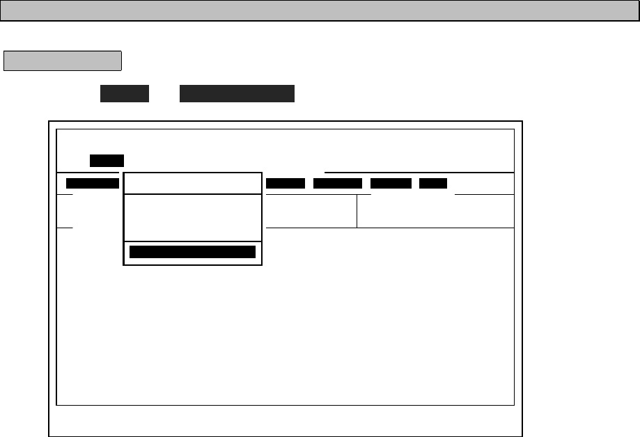
1. Select Tune Î
ÎÎ
Î Scanning stop and press Enter key.
2. Scanning is stopped and the NCT-196N returns to stand-by condition.
The Tx/Rx frequency is set to the frequency scanned last.
[TLX] Tx=12345.6kHz / Rx=12345.6kHz (ITU CH= 0) 10-APR-2002 12:00(LT)
Loc: N19.00 E115.30 at 11:00(UTC)
File Tune Connect Service System Help
[ STATUS INFO ]
Scanning info Tuner/Tx.POWER
[No scanning] TUNER :[READY]
Tx.POWER:[FULL]
Last status messages
Move the cursor to the item you want with ↑,↓,→,← then press Enter
ST-BY
Tune
Frequency List
ITU Channel set
Tx/Rx frequency set
Tx. Tune
Scanning start
Scanning stop
3-87
3.7 PA operations
The NAH-692 Power Amplifier connected to JSB-196GM can be used basically without any settings after
installation. However for checking such as output power, voltages or currents or for setting such as alarm or
charge mode, the NAH-692 Power Amplifier has functions as described below.
3.7.1 AC/DC power source voltage checking
Procedure
1. Press Menu button and turn the dial to “AC/DC VOLTAGE” menu on the LCD.
AC,DC VOLTAGE
2. Press ENT button.
The menu is selected and LCD shows the AC/DC voltages.
AC Volt 221V
DC Volt 24.2V
3. After completed, press Menu button again to return to menu selection.
3.7.2 DC (Battery) charge/discharge current checking
Procedure
1. Press Menu button and turn the dial to “DC CURRENT” menu on the LCD.
DC CURRENT
2. Press ENT button.
The menu is selected and LCD shows the value of DC (Battery) charge/ discharge current.
DC CURR +2.5A
(- : DISCHG,+ : CHG)
3. After completed, press Menu button again to return to menu selection.
3-88
3.7.3 RF current of Antenna and PA checking
Procedure
1. Press Menu button and turn the dial to “ANT, PA CURR” menu on the LCD.
ANT, PA CURR
2. Press ENT button.
The menu is selected and LCD shows the value of Antenna and PA current.
ANT CURR 0.0 A
PA CURR 0.0 A
3. After completed, press Menu button again to return to menu selection.
3-89
3.7.4 PA voltage (Vc) and current (Ic) checking
Procedure
1. Press Menu button and turn the dial to “ PA(A) Vc, Ic ” menu on the LCD.
PA (A) Vc, Ic
2. Press ENT button.
The menu is selected and LCD shows the Vc and Ic values of PA(A) .
PA(A) Vc 0 V
PA(A) Ic 0.0 A
3. After completed, press Menu button again to return to menu selection.
Note) When checking the Vc and Ic for PA(B) or PA(C), substitute the above “PA(A)” for “PA(B)” or
“PA(C)”. Furthermore, the components of PA(A/B/C) differs by the type of NAH-692/ 695/
698 respectively such as the following table.
PA (A) PA (B) PA (C)
NAH-692 (250W)
NAH-695 (500W)
NAH-698 (800W)

3-90
3.7.5 SWR of PA output checking
Procedure
1. Press Menu button and turn the dial to “PA SWR” menu on the LCD.
PA SW R
2. Press ENT button.
The menu is selected and LCD shows the SWR value of PA output.
SWR (A)
--.--
3. After completed, press Menu button again to return to menu selection.
Note) When checking the SWR for PA(B) or PA(C), substitute the above “PA(A)” for “PA(B)” or
“PA(C)”. Furthermore, the components of PA(A/B/C) differs by the type of NAH-692/ 695/
698 respectively such as the following table.
PA (A) PA (B) PA (C)
NAH-692 (250W)
NAH-695 (500W)
NAH-698 (800W)
3-91
3.7.6 Beeping sound ON/OFF setting
Procedure
1. Press Menu button and turn the dial to “TOUCH TONE” menu on the LCD.
TOUCH TONE
2. Press ENT button.
The menu is selected and LCD shows setting of TOUCH TONE.
TOUCH TONE
ON
3. Turn the dial to select ON or OFF.
TOUCH TONE
OFF
4. Press ENT button to set it and return to menu selection.
3.7.7 Alarm sound ON/OFF setting
Procedure
1. Press Menu button and turn the dial to “ALARM TONE” menu on the LCD.
ALARM TONE
2. Press ENT button.
The menu is selected and LCD shows setting of ALARM TONE.
ALARM TONE
ON
3. Turn the dial to select ON or OFF.
ALARM TONE
OFF
4. Press ENT button to set it and return to menu selection.
3-92
3.7.8 Battery charge mode (Ordinary/Equal) setting
Procedure
1. Press Menu button and turn the dial to “CHARGE METHOD” menu on the LCD.
CHARGE METHOD
2. Press ENT button.
The menu is selected and LCD shows setting of CHARGE METHOD.
CHARGE METHOD
ORDINARY
3. Turn the dial to select ORDINARY or EQUAL.
CHARGE METHOD
EQUAL
ORDINARY: Automatic charge mode where the battery is kept fully-charged. This mode is
normally used.
EQUAL: Equaizing charge mode.
After setting it as EQUAL mode, when charge current decreased, or when charge
time has passed for 2 hours, it changes to ORDINARY mode automatically.
4. Press ENT button to set it and return to menu selection.
When charge mode changes the EQUAL to the ORDINARY, JSB-196GM may turn off. In
this case turn on the JSB-196GM.
3.7.9 DC operation
Attention for DC operation
1. Single Setting
Either JSB or SES is usable in this setting.
・Turn on JSB-196GM : SES is turned off automatically.
(JSB-196GM shows “SES OFF” on LCD.)
・Turn off JSB-196GM : SES is turned on automatically after 30-60sec.
2. Dual Setting
Both JSB and SES are simultaneously usable in the setting.
Refer to “Installation manual” about Single/Dual setting.
Note
Note
3-93
3.8 Printer operations
The contents of the communication files and messages can be printed out if connected the NKG-800 Printer to the
NCT-196N DSC/NBDP MODEM and the NDZ-127J DTE via NCF-1960 PRN SELECTOR. This chapter describes
the printer operation, paper roll loading, ribbon cassette cartridge replacement and how to set the DIP switch.
CAUTION
Notes on using the printer
Be sure to turn OFF the printer’s power when opening and closing the printer cover.
Failure to comply could result in electrical shock, failure, or injury.
Do not drop or strike the printer.
Doing so may cause failure or malfunction.
Just after printing, the temperature of the printing head is high.
Do not touch the printing head until the temperature goes down.
Doing so may cause a burn or an injury.
Never try to disassemble or repair the printer yourself.
Doing so may cause failure or malfunction.
Do not touch any part of the cutter.
Doing so is potentially dangerous.
When attaching the ribbon, be sure it does not get twisted.
Doing so may cause failure or malfunction.
Wait at least two seconds to restart the system after turning the power switch OFF.
Otherwise the initialization may not proceed correctly or a malfunction may occur.
Do not attempt to print without the ribbon cassette cartridge or paper.
Doing so may cause failure or malfunction.
When the printer is working, be sure not to allow your hands, any articles of clothing
or accessories (a necktie or jewelry for instance) too close to the unit.
Doing so may cause injury.
Do not place anything such as liquids or metals on top of the printer.
They may drop into the printer, causing fire or malfunction.
Do not install the printer in the following locations.
Doing so may cause a fire, malfunction or degradation of printing quality.
・On a surface that is not horizontal, or where the vibration is severe.
・In a location subject to direct sunlight or excessive dust.
・In a location subject to extremely high or low temperatures.
・In a location subject to excessive humidity.
3-94
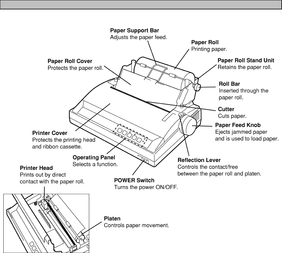
3.8.1 Names and Functions
3-95
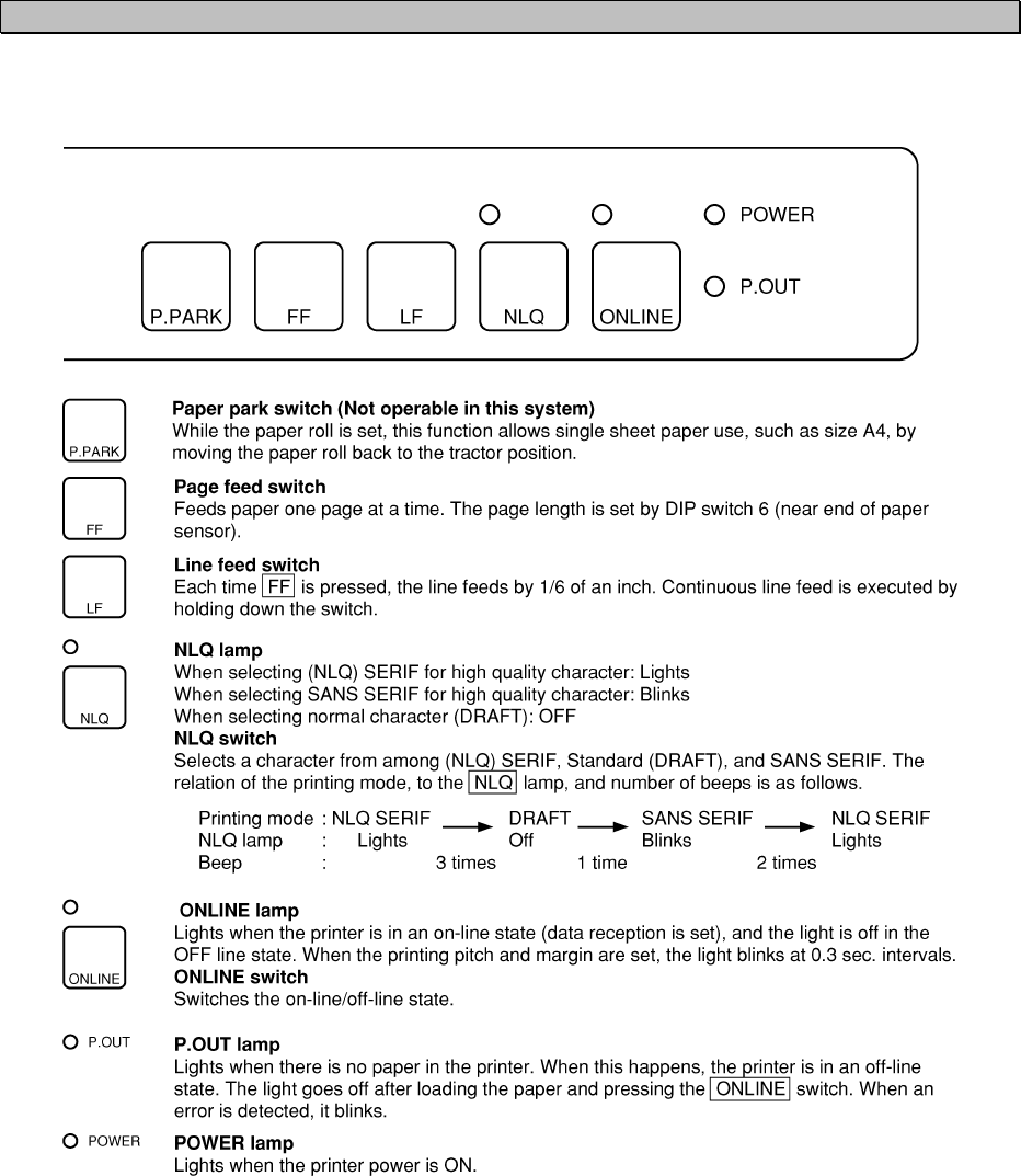
3.8.2 Operating Panel
From the operating panel, switching on-line/off-line, selecting of high quality characters, forced line feed, and
forced page feed can be controlled.
3-96
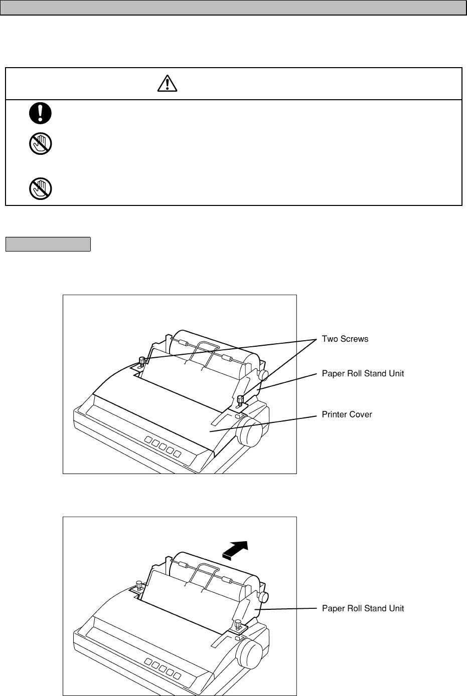
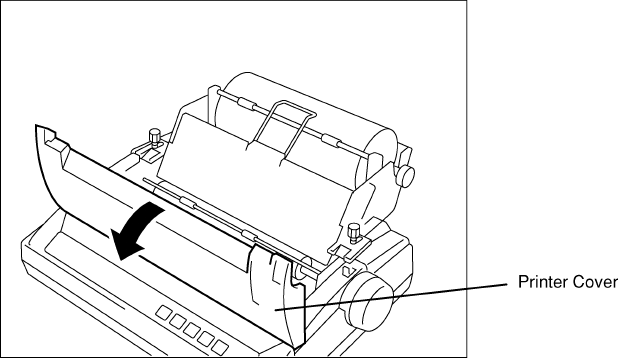
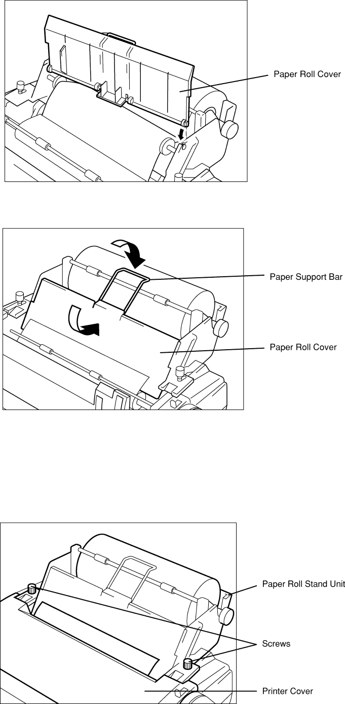
3.8.3 Opening / Closing the Printer Cover
When opening the printer cover, move the paper roll stand unit one step back. To open/close the printer cover,
follow the procedures consecutively.
CAUTION
Be sure to turn OFF the printer's power when opening and closing the printer cover.
Failure to comply could result in electrical shock, failure, or injury.
Just after printing, the temperature of the printing head is high. Do not touch the
printing head until the temperature goes down.
Failure to comply could result in a burn or injury.
Do not touch any part of the cutter. Doing so is potentially dangerous.
Procedure
1. Loosen the two screws holding the paper roll stand unit fixed.
When closing the printer cover, follow the steps in reverse order.
2. Move the paper roll stand unit one step backwards.
3-97
3. Open the printer cover.
3-98
3.8.4 Replacing the Roll Paper
When replacing the paper roll, proceed as follows.
CAUTION
Be sure to turn OFF the printer power when opening and closing the printer cover.
Failure to comply could result in electrical shock, failure, or injury.
Just after printing, the temperature of the printer head is high. Do not touch the printer head
until the temperature goes down.
Failure to comply could result in a burn or injury.
Do not touch any part of the cutter. Doing so may result in injury.
Procedure
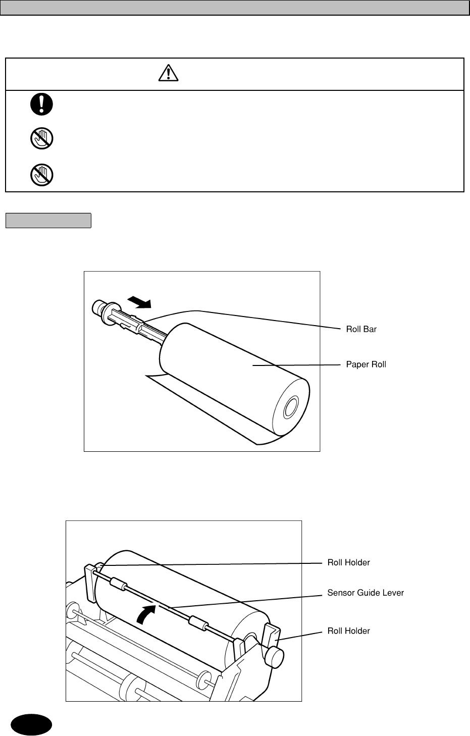
1. Insert the roll bar through the center of the paper roll.
If the leading edge of paper is torn or bent, cut it off in a straight line.
2. Attach the roll bar with the paper roll onto the paper roll stand unit holder, taking
care to notice he paper roll's direction.
Set the sensor guide lever so that it touches the paper roll.
・ Perform the consecutive procedures while the printer cover is open.
・ To open the printer cover, refer to "9.3 Opening/Closing the Printer Cover".
Note
3-99
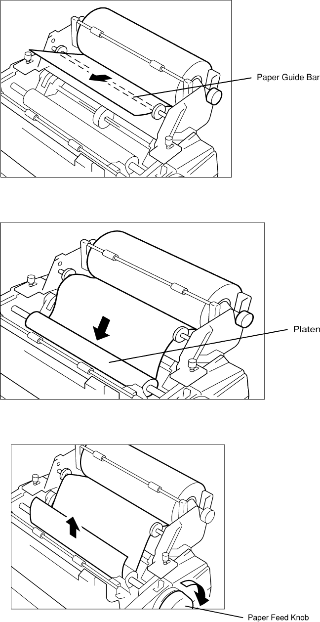
3. Pull out the leading edge of the paper onto the paper guide bar.
4. Insert the leading edge of the paper from behind the platen
5. Turn the paper feed knob and pull out the leading edge of the paper.
3-100
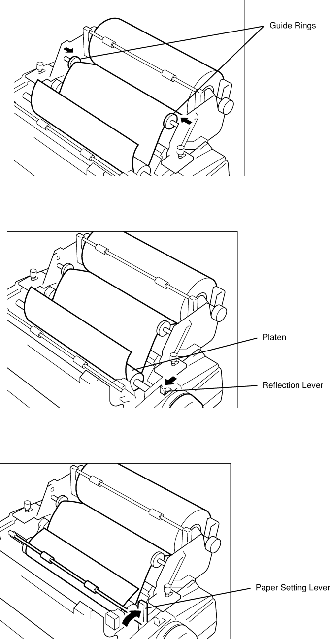
6. Adjust the paper position for both sides of paper in and paper out, so that the left
and right guide rings of the paper guide bar support the paper lightly.
7. Pull down the reflection lever.
The paper touches the platen securely.
8. Pull down the reflection lever.
Lift the paper setting lever to harness the paper emerging from the platen.
3-101
9. First, insert the axis of the left side of the paper roll cover into the left hole of the
paper roll stand, then set the right side.
10. Lower the paper roll cover and then push down the paper support bar.
11. Close the printer cover.
For further details of steps 11 through 13, refer to "9.3 Opening/Closing the Printer Cover".
12. Pull the paper roll stand unit one step forward.
13. Turn the screws tightly to stabilize the paper roll stand unit.
3-102
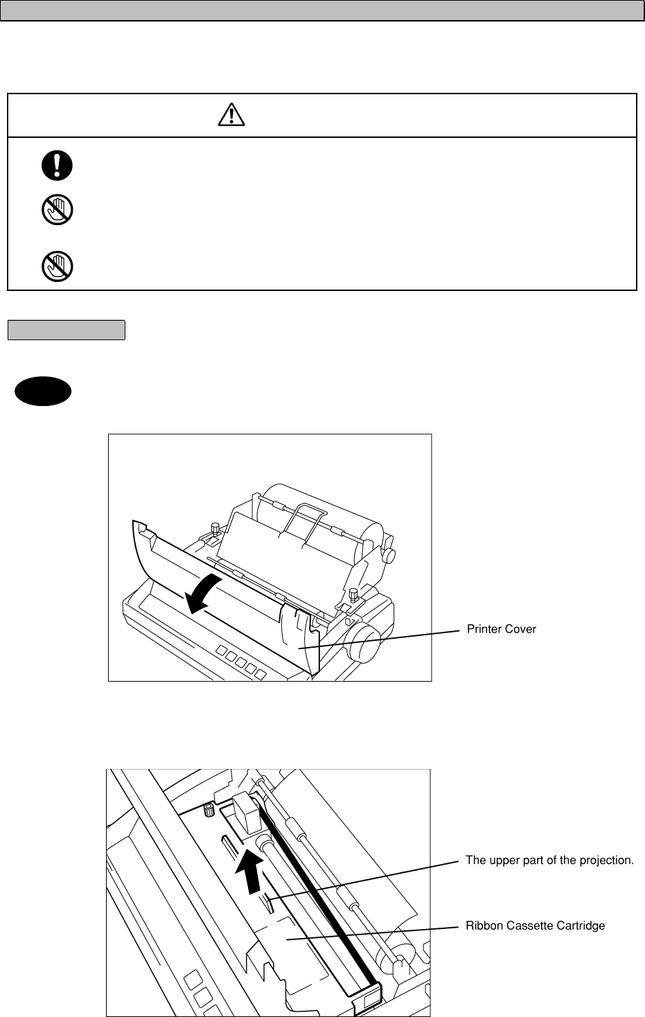
3.8.5 Replacing the Ribbon Cassette Cartridge
When the printing quality becomes faint, replace the ribbon cassette cartridge with a new one.
To replace, proceed as follows.
CAUTION
Be sure to turn OFF the printer power when opening and closing the printer cover.
Failure to comply could result in electrical shock, failure, or injury.
Just after printing, the temperature of the printer head is high. Do not touch the printer head
until the temperature goes down.
Failure to comply could result in a burn or injury.
Do not touch any part of the cutter. Doing so may result in injury.
Procedure
1. Open the printer cover.
・ To open the printer cover, refer to "7.3 Opening/Closing the Printer Cover".
2. Lift up the tip of the ribbon cassette cartridge by grasping the projection on top,
and remove it.
Note
3-103
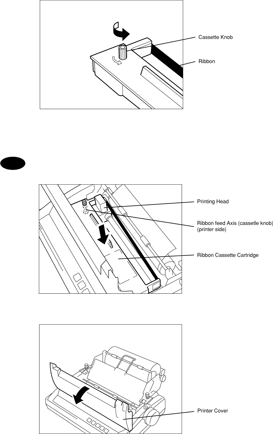
3. Turn the cassette knob of the new ribbon cassette cartridge counterclockwise to
increase the tension of the ribbon.
4. Manually, move the printing head to the home position (left side) and place the
ribbon cassette cartridge in the printer so that the ribbon is positioned between
the ribbon mask and the printing head. In this case, make sure that the ribbon feed
axis is inserted through the hole under the ribbon cassette knob.
・ Lightly press the ribbon cassette cartridge at both ends.
・ Turn the cassette knob again to increase the tension of the ribbon.
・ Confirm that the ribbon is positioned properly in front of the printing head.
5. Close the printer cover
Note
3-104
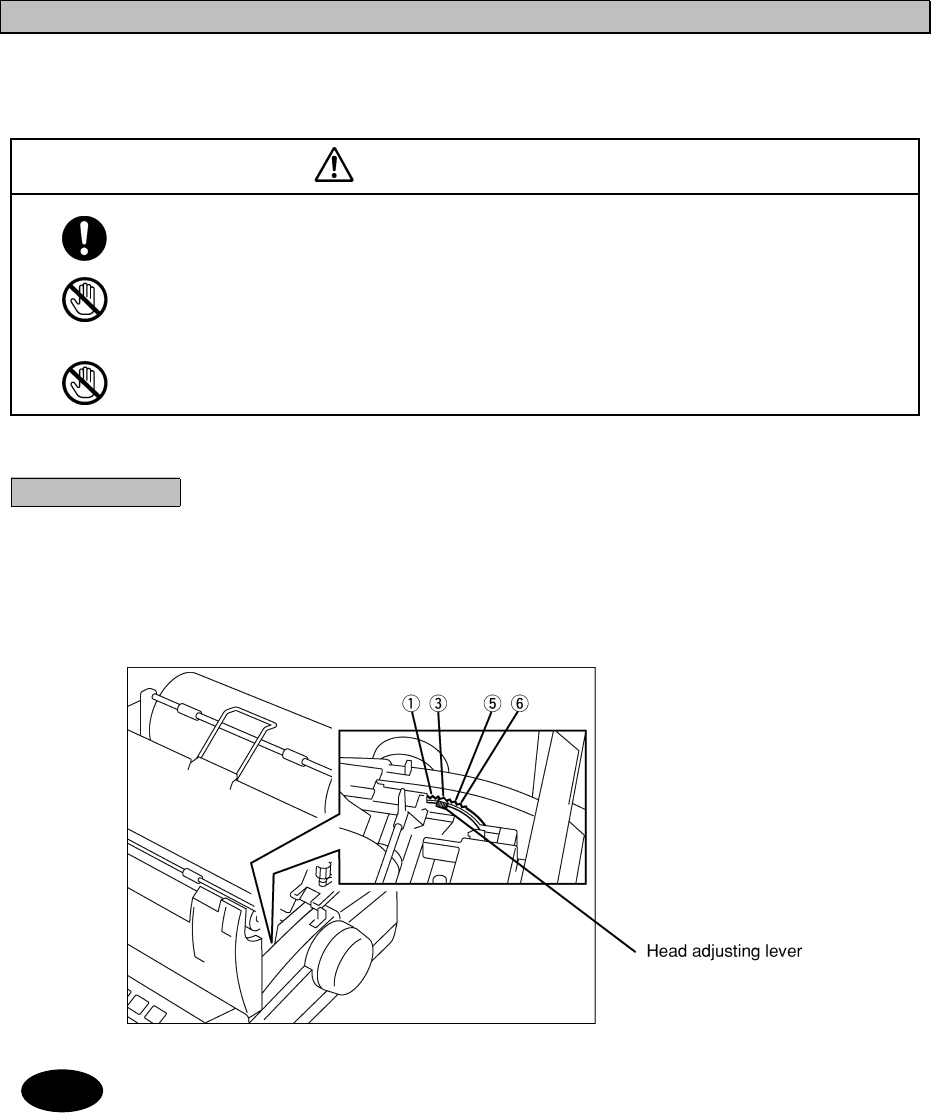
3.8.6 Adjusting the Printing Pressure
(to Printing Paper Thickness)
The printing pressure can be adjusted with the head adjust lever located on the right side of the inner part of the
printer.
CAUTION
Be sure to turn OFF the printer power when opening and closing the printer cover.
Failure to comply could result in electrical shock, failure, or injury.
Just after printing, the temperature of the printer head is high. Do not touch the printer head
until the temperature goes down.
Failure to comply could result in a burn or injury.
Do not touch any part of the cutter. Doing so may result in injury.
Procedure
1. Open the printer cover and set up the head adjusting lever.
Each type of paper should be set as follows:
Normal paper : The optimal position among the numbers shown is ③.
Three layers of copying paper : The optimum position is ⑤ or ⑥.
・ The printing pressure increases in numerical order (①→⑥).
・ To open/close the printer cover, refer to "7.3 Opening/Closing the Printer Cover".
Note
3-105
3.8.7 Setting the DIP Switch
Set the DIP switch to select a language, character set, or particular function.
ATTENTION
Before beginning the procedure, be sure to turn the power OFF.
Failure to do so may cause electrical shock, malfunction or injury.
Just after printing, the temperature of the printer head is high. Do not touch the printer head
until the temperature goes down.
Doing so may cause burns or injury.
Do not touch any part of the cutter.
Doing so is potentially dangerous and may cause injury.
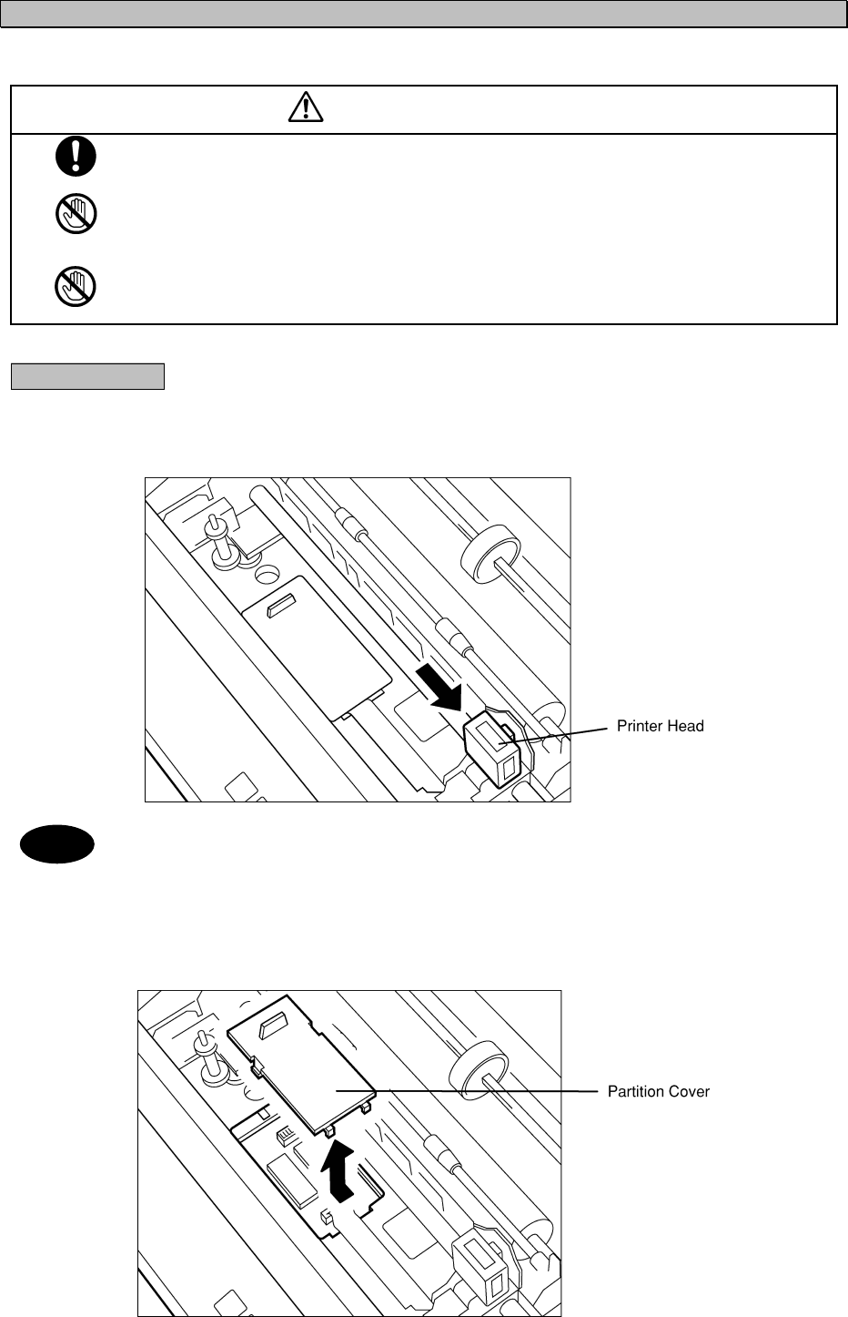
Procedure
1. Open the printer cover, remove the ribbon cassette cartridge, and move the
printing head manually to the right end.
・ The printing pressure increases in numerical order (①→⑥).
・ To open/close the printer cover, refer to "7.3 Opening/Closing the Printer Cover".
・ To remove the ribbon cassette cartridge, refer to "7.5 Replacing the Ribbon Cassette Cartridge".
2. Hold the tip of the partition cover and slide it to the left to remove it.
The DIP switch appears.
Note

3-106
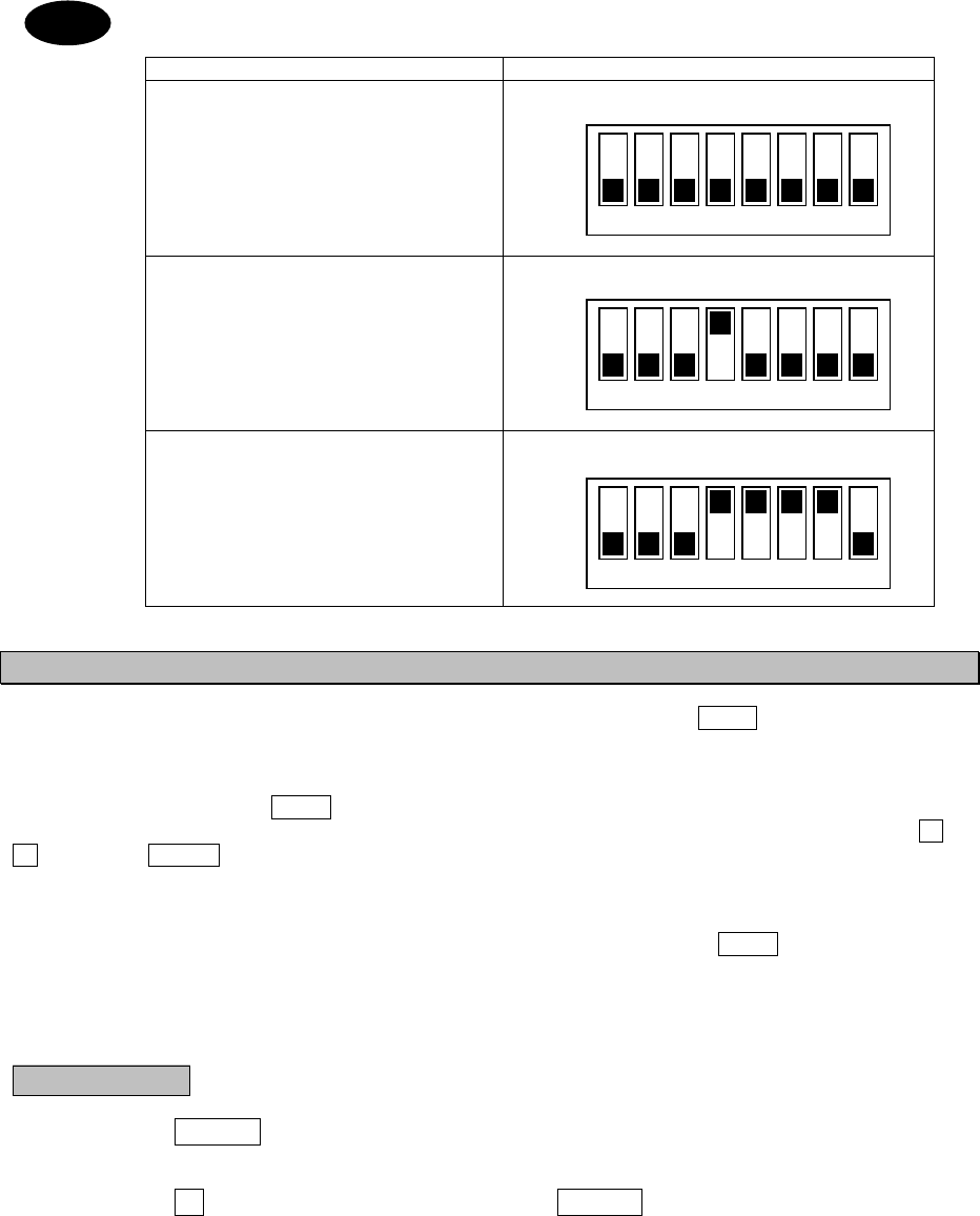
3. Set the DIP switch to desired mode
The following diagrams describe the relation between each DIP switch position and the content of each
setting.
4. When settings are completed, put the partition cover back in its place, set up the
ribbon cassette, and then close the printer cover.
5. While pressing NLQ turn the power ON.
After initialization is carried out, the selected function and current setting status of the DIP switch are
printed.
・ When printing under the current setting status, the printer is set to an off-line state. When the test
pattern is completely printed out, it is automatically set to an on-line state.
Note
3-107
Dip switch setting for each equipment.
DIP switch setting
JSS-296(NCT-196N/NDZ-127J)
JSS-825D(NCT-620D)
NCT-196
NCT-196N
JSS-850
JUE-75C(NDZ-127C)
JSS-825NA/NC(NDZ-127N)
3.8.8 How to Attend to Error Detection
There are two types of errors. When an error is detected, a beep sounds, and the P.OUT lamp blinks 5 times.
(1) Paper discharge error
When the "out of paper" state is not detected, even though an 18 inch line feed procedure is performed, a paper
discharge error will result. The P.OUT lamp remains blinking until the error state is canceled.
When this happens, manually pull the paper out of the printer, or remove the paper automatically by using LF or
FF , then press ONLINE .
(2) Paper sending error
If the paper is not properly set, even though a 10 inch line feed procedure is performed, a paper sending error
results. In addition, if this error happens when the printing instruction is entered, the P.OUT lamp remains blinking
until the error state is canceled.
When this happens, follow the procedure below.
Procedure
1. Press ONLINE switch.
The printer is set to an off-line state.
2. Press FF switch, set the paper, then press ONLINE .
The printer is set to an on-line state.
12345678
OFF
ON
DIP switch
12345678
OFF
ON
DIP switch
12345678
OFF
ON
DIP switch
Note
3-108
4-1
4.
MAINTENANCE AND INSPECTION
The performance and longevity of this equipment depend on careful maintenance. To maintain the best
performance, the following periodic inspections are highly recommended.
(1) Keep the power supply voltage within the specified value.
(2) Know the condition of normal status when the equipment is properly functioning. Keep comparing the
current status to the normal status to immediately detect any malfunctions.
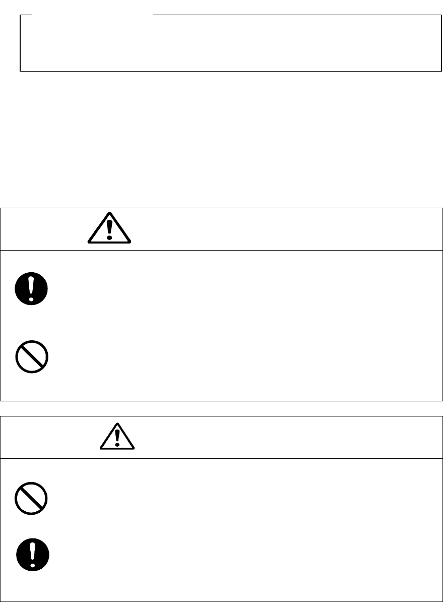
WARNING
If you remove a unit, be sure to store it in a non-conductive bag. If you wrap
It up with materials such as aluminum foil, the back-up power supply may S
hort circuit and the ICs may be damaged.
There are no user-serviceable parts inside this equipment. Inspection or
maintenance by unauthorized persons may result in fire or electric shock.
For inspection and maintenance, contact JRC or its authorized agents.
CAUTION
Do not turn the trimmer resistors or trimmer capacitors on the PCB unit (they are preset
at the factory). Doing so may cause failure or malfunction.
Leave installation of this equipment to JRC or our agents. Installation by an
unauthorized person may lead to malfunction.
This chapter describes about the JSS-296 Radio Equipment as a whole. So if further information
is required, see the specialized instruction manuals such as the JSB-196GM Radiotelephone or NCT-196N
DSC/NBDP MODEM.
ATTENTION

4-2
4.1 General Maintenance and Inspection
General maintaining and inspecting items with usual tools and apparatus are listed below.
No. Item Maintenance and inspection
1 Cleaning
Gently clean the surface of the panel, knobs, switches, and upper/bottom cover with
a soft cloth or silicon oil.
Remove dust in the unit using a brush or vacuum cleaner. No oil is needed because
this unit has no moving mechanisms inside.
2Looseness
of parts
Inspect for looseness and correctly tighten the following:
screws, nuts, knobs, switches, volume pots, connectors and relays inserted into
sockets.
3Fuse If the power source fuse is blown, be sure to inspect the cause before replacing the
blown fuse with a new one.
4 PCB Unit
Remove screws mounting the unit, demount the unit from the main chassis, and
inspect the unit for discoloration and parching of components. To exchange parts,
call our service center or agents.
If you remove the PCB unit, be sure to store it in a non-conductive bag. If you wrap it up with materials such
as aluminum, the buck-up power supply may short circuit and the IC may be damaged.
Note

5-1
5.
AFTER-SALES SERVICE
5.1 Before returning repair
If what appears to be a defect is detected, refer to Troubleshooting descriptions of the specialized instruction
manual for every unit to check if the equipment is actually defective before requesting repair.
If the defect persists, immediately stop operation and call our service center or agents.
z During the warranty period, we or our agencies (*1) will repair the malfunction without any fee,
according to the specified procedure.
z After the warranty expires, we will repair the malfunction for a fee, if repair is possible.
z Items for notification
- Product name, type, manufactured data, serial number,
- information about the malfunction (the more detailed, the better),
- your company or organization name, address and phone number.
(*1) Refer to the inside of the back cover for contact numbers.
5.2 Periodical maintenance recommended
Performance of this equipment may degrade over time because parts wear out, although degradation depends
on how this unit has been maintained, thus we recommend periodic professional maintenance checks in
addition to daily maintenance. So please contact our service center or agents for periodic professional
maintenance (This maintenance requires a service charge), or for further information about after-sales service.
5-2

6-1
6.
SPECIFICATIONS
1. GENERAL
Frequency range: Transmit: 1.6 to 27.5MHz (100Hz steps)
Receive: 0.1 to 29.9999MHz (100Hz steps)
Frequency tolerance: ±10Hz or better
Emission mode: J3E (TEL), F1B (DSC/TLX), A1A (CW), H2B,
H3E (AME: reception only)
User definable channels: 200ch (20ch X 10 Groups)
Preset ITU channels: 1722ch [ TEL:283, DSC:29, TLX:891, CW:519 ]
Scanning channel 20 user defined channels
Communication mode: Simplex and semi-duplex
Antenna impedance:
Operating temperature:
Power requirement:
50 ohms
-15 to +55oC
90∼132V/180∼264V AC, Single-phase, 50/60Hz
Tx: 2.0kVA max, Rx: 0.5kVA max
21.6∼31.2V DC
Tx: 30A max, Rx: 7A max
Compass safe distance: 1.5m
2. TRANSMITTER
Output power: AC power source:
200Wpx ( 1.6 to 4MHz ) , 250Wpx ( 4 to 27.5MHz )
DC power source:
100Wpx ( 1.6 to 4MHz ) , 150Wpx ( 4 to 27.5MHz )
Occupied bandwidth: J3E (TEL) 3kHz or better
F1B (DSC/TLX), A1A (CW) 0.5kHz or better
Carrier suppression: 40dB or better
Spurious suppression: 43dB or better
AF frequency response: 350 to 2700Hz (6dB bandwidth)
Microphone input: 600 ohms (-40dBm standard)
Line input: 600 ohms, 0dBm (balanced)

6-2
3. RECEIVER
Receiving system: Triple superheterodyne
Intermediate frequencies: 70.455MHz, 455kHz, 20.217kHz
Sensitivity (SINAD 20dB): J3E (TEL) 6.3uV or better (1.6 to 4MHz)
3.5uV or better (4 to 27.5MHz)
F1B (DSC/TLX) 1.8uV or better (1.6 to 4MHz)
1.0uV or better (4 to 27.5MHz)
Selectivity: J3E (TEL) 6dB bandwidth 2.4 to 3kHz,
66dB bandwidth Within ±2.1kHz
F1B (DSC/TLX) 6dB bandwidth 270 to 300Hz,
60dB bandwidth Within ±550Hz
Spurious response: 60dB or better
Clarifier range: ±200Hz in 1Hz steps
AF output: 5.0W max. 1W rated
Line output: 600 ohms, 0dBm (balanced)
4. DSC/NBDP TERMINAL
DSC MODEM
Communications protocol: In conformity with ITU-RM.493 and M.541
Emission: F1B/J2B 100 baud
Code: 10 units error detection specified by ITU-RM.493.
Memory capacity: Received Distress messages: 20
Received Other messages: 20
Transmitted message: 11
Clock: Within +/- 30ppm
Data backup time: 24 hours (message content and time data)
Mark frequency: 1615 +/- 0.5Hz
Space frequency: 1785 +/- 0.5Hz
Output level: 0dBm (-20 to +10dBm variable/600 ohms balanced)
Input frequency : 1700 +/- 85Hz
Input level : -25 to +10dBm (600-ohm balanced load)
NBDP MODEM
Communications protocol: In conformity with ITU-RM.476, M.490, M.491, M.492, M.625
and ITU-T Rec. F130
Emission: F1B/J2B 100 baud
Code: 7-bit code 4B/3Y ratio constant mark signal
Clock: Within +/- 30ppm
Mark frequency: 1615 +/- 0.5Hz
Space frequency: 1785 +/- 0.5Hz
Output level: 0dBm (-20 to +10dBm variable/600 ohms balanced)
Input frequency : 1700 +/- 85Hz
Input level : -25 to +10dBm (600-ohm balanced load)

6-3
5. WATCHKEEPING RECEIVER
Receiving frequencies: 2187.5kHz、4207.5kHz、6312kHz、8414.5kHz、12577kHz、
16804.5kHz
Receiving system: Double superheterodyne
Intermediate frequencies: 40.455MHz, 455kHz
Reception mode: F1B/J2B
Sensitivity: Symbol error rate of 1% or better at 1 micro-volt input
Frequency stability: Within +/- 10Hz after 1-minute warm-up
Antenna impedance: 50 ohms unbalanced
6. ANTENNA TUNER
Frequency range: 1.6 to 30MHz
Power capability: 300Wpx
SWR after tuning: 2:1
Tuning method: Automatic tuning and preset tuning
Tuning time: Automatic tuning: typical 3sec
Preset tuning: typical 0.5sec
Operating temperature: -25 to +55 oC
7. BATTERY CHARGER
Charging current: 20A (Ordinary charge)
10A (Equalizing charge)
Alarm function: Charge /Low voltage/ High voltage alarm
8. DATA TERMINAL
Controlled item: NBDP function (Control the DSC/NBDP Terminal)
9. KEYBOARD
Interface: Matrix
Contact method: Membrane sheet
Life: 5 million strokes
10. PRINTER
Print method: Serial impact dot matrix
Interface: Centronics
Paper feed method: Paper roll holder
Paper type: 209 to 216mm Roll paper
Main Office & Plants ● Main Office ● Mitaka Plant
Akasaka Twin Tower(Main) 1-1,Shimorenjaku 5-chome,Mitaka
17-22,Akasaka 2-chome, Tokyo 181-8510 JAPAN
Minato-ku,Tokyo 107-8432 JAPAN Phone :+81-422-45-9111
Maritime Sales DepartmentⅠ Fax :+81-422-45-9110
Phone :+81-3-3584-8786
Fax :+81-3-3584-8795
Maritime Sales DepartmentⅡ
Phone :+81-3-3584-8790
Fax :+81-3-3584-8797
International Business Department
Phone :+81-3-3584-8836
Fax :+81-3-3584-8878・3584-8859
International Marketing Department
Phone :+81-3-3584-8845
Fax :+81-3-3584-8879
Overseas Branch Office ● U.S.A ● JRC (UK) Limited
Japan Radio Co.,Ltd./Seattle Branch 136,1st Floor,Friars House,
1011 SW Klickitat Way 157/168 Blackfriars Road,
Bldg.B,Suite 100 London SE18 EZ,U.K.
Seattle,WA 98134 U.S.A Phone :+44-20-7261-1188
Phone :+1-206-654-5644 Fax :+44-20-7803-0996
Fax :+1-206-654-7030
●
●●
● U.S.A
Japan Radio Co.,Ltd./New York Branch
Suite 209 2125 Center Avenue,
Fort Lee, N.J. 07024, U.S.A.
Phone :+1-201-242-1882
Fax :+1-201-242-1885
Overseas
Liaison & Service Offices ● Indonesia ● Taiwan
Japan Radio Co.,Ltd. Japan Radio Co.,Ltd
J1.H.R.Rasuna Said Kav. 10F-4,No.110,Santou 4th Road,
X-0,Jakarta 12950,INDONESIA Kaohsiung Taiwan,R.O.C
Phone :+62-21-520-4053 Phone :+886-7-3307151
Fax :+62-21-525-4264 Fax :+886-7-3319400
● Philippines ● Spain
Japan Radio Co.,Ltd. Japan Radio Co.,Ltd.
2320 Taft Avenue Calle Luis Doreste Silva,50-1-B
Malate,Manila PHILIPPINES De Las Palmas De Gran Canaria, SPAIN
Phone :+63-2-524-8565・525-3589 Phone :+34-928-290076
Fax :+63-2-521-5049 Fax : +34-928-293755
● Thailand ● Singapore
Japan Radio Co.,Ltd. Japan Radio Co.,Ltd
Charturong Arphon Building, c/o CODAR(PTE.)LTD
457 Phra Sumaru Street, 315 Outram Road #11-06/07 Tan Boon Liat
Bangkok 10200,THAILAND Building Singapore 169074,SINGAPORE
Phone /Fax :+66-2-280-0401 Phone :+65-2229190
Fax :+65-2229398
● India ● Greece
Japan Radio Co.,Ltd. Japan Radio Co.,Ltd.
Best Western Surya Hotel, Akti Miaoli 57,Piraeus,Greece
Business Center New Friends Phone :+30-1-429-3304・429-3305
Colony,New Delhi 110065, Fax :+30-1-429-3306
INDIA
Phone :+91-11-691-9294・691-9297
Fax :+91-11-691-9305
Overseas Service Center ● Netherlands
Japan Radio Co.,Ltd.
Eekhoutstraat-7,
3087AB Rotterdam, THE NETHERLANDS
Phone :+31-10-429-4581・495-0020
Fax :+31-10-428-2259

HEAD OFFICE & Akasaka Twin Tower (Main),
SALES DEPT. 17-22, Akasaka 2-chome, Minato-ku,
Tokyo 107-8432 JAPAN
Phone : +81-3-3584-8711
Fax : +81-3-3584-8715
Telex : 0242-5420 JRCTOK J
MAIN PLANT 1-1, Shimorenjaku 5-chome, Mitaka-shi,
Tokyo 181-8510 JAPAN
Phone : +81-422-45-9111
Fax : +81-422-45-9110
Telex : 02822-351 JRCMTK J
CODE No.: 7ZPJD0162
Since 1915
For further information contact:
FIRST EDITION
SEP. 2002