Japan Radio JSS-296 MF/HF Radio Telephone User Manual 1
Japan Radio Co Ltd. MF/HF Radio Telephone 1
UserManual.wiki
>
Japan Radio
>
JSS-296 User Manual
>
Pages 1 to 77
Contents
1.
Pages 1 to 77
2.
Pages 78 to 154
Pages 1 to 77
Navigation menu
Upload a User Manual
Namespaces
Wiki Guide
HTML
PDF
Info
Views
User Manual
Discussion / Help
Navigation
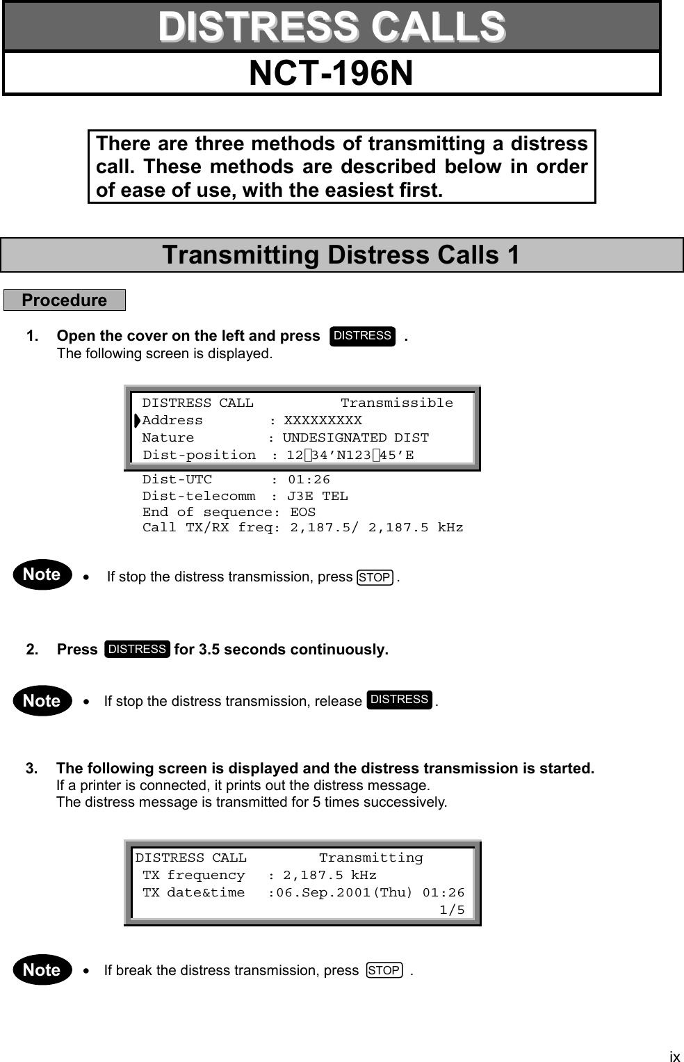
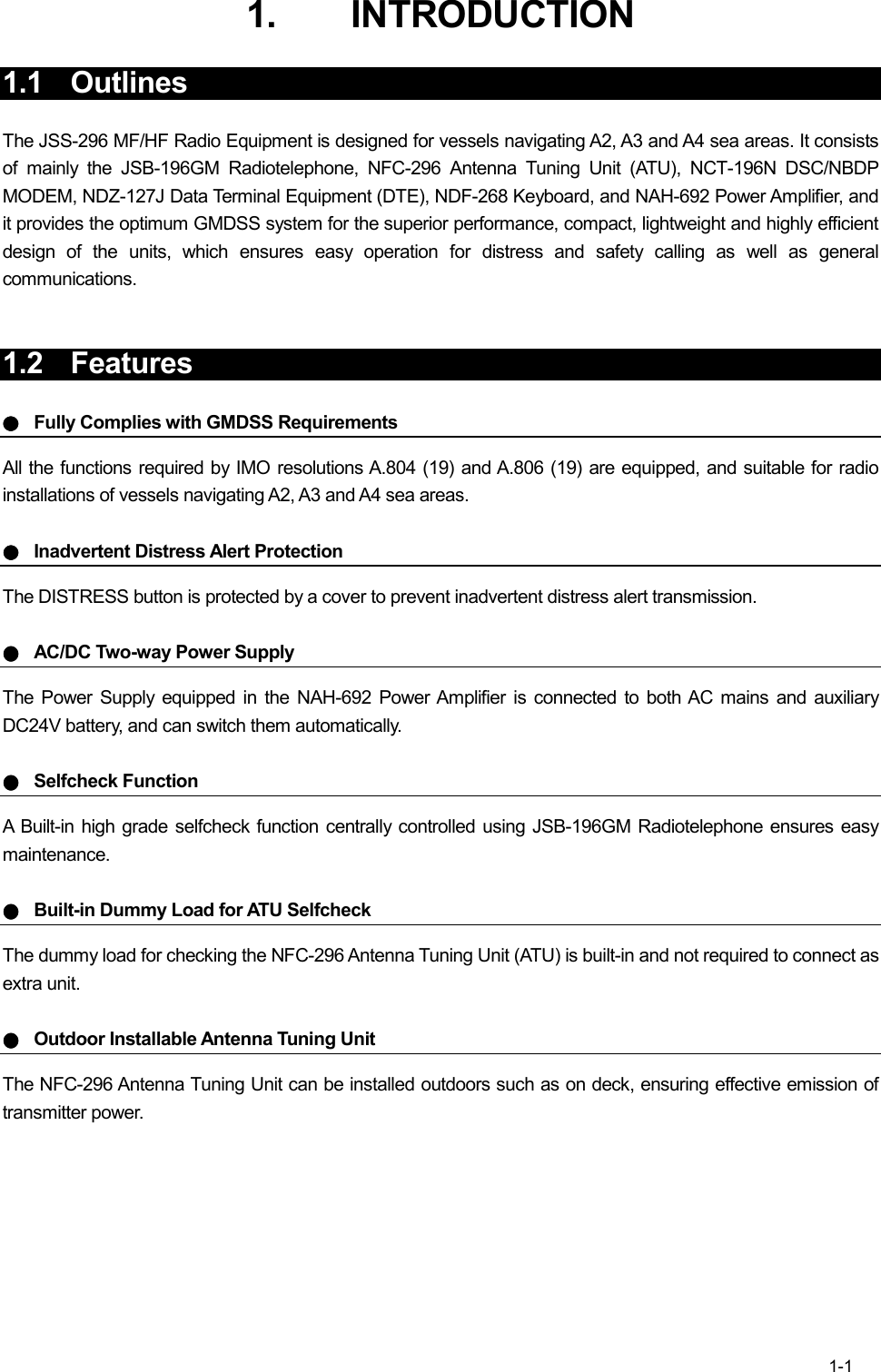
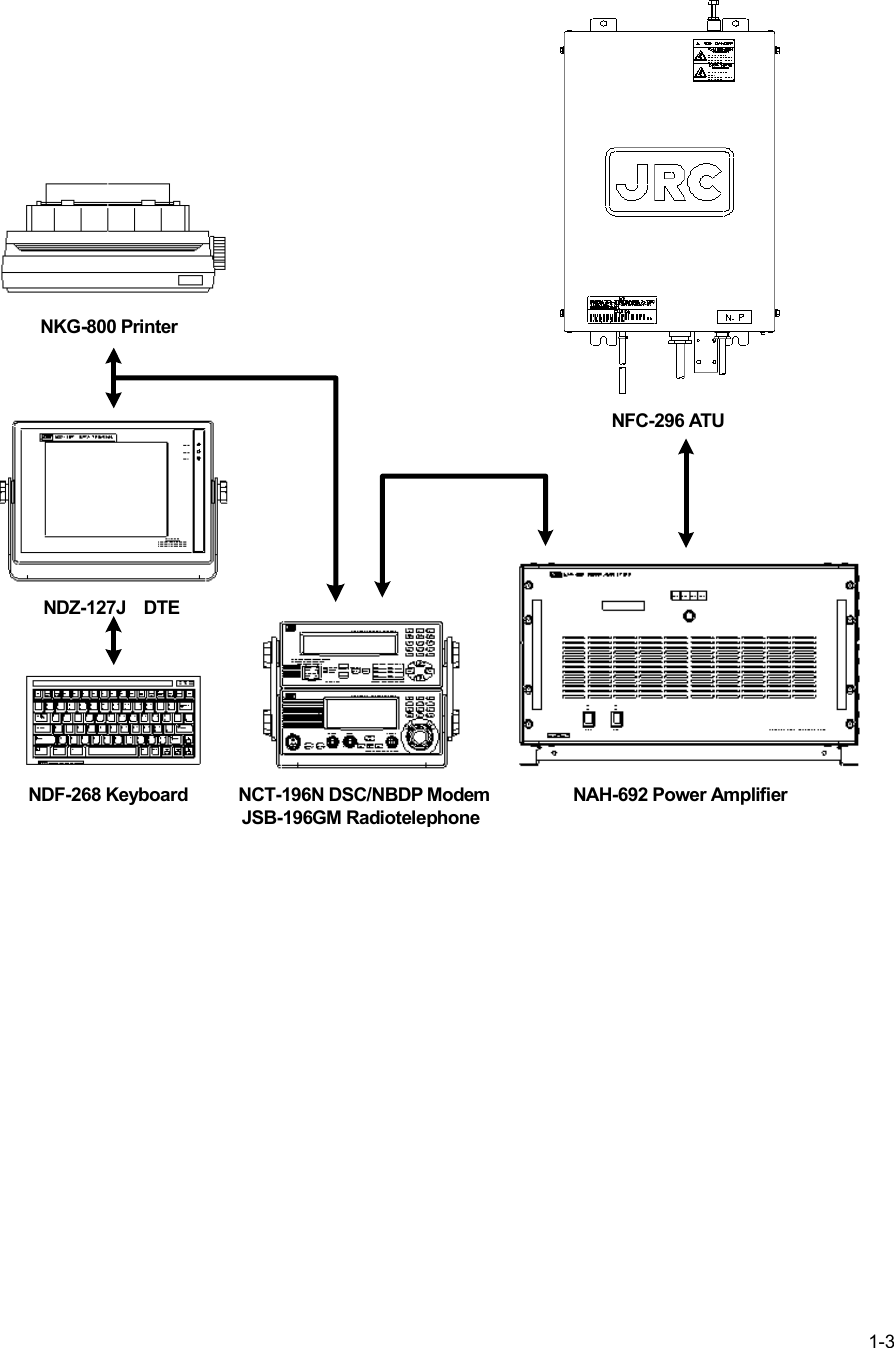
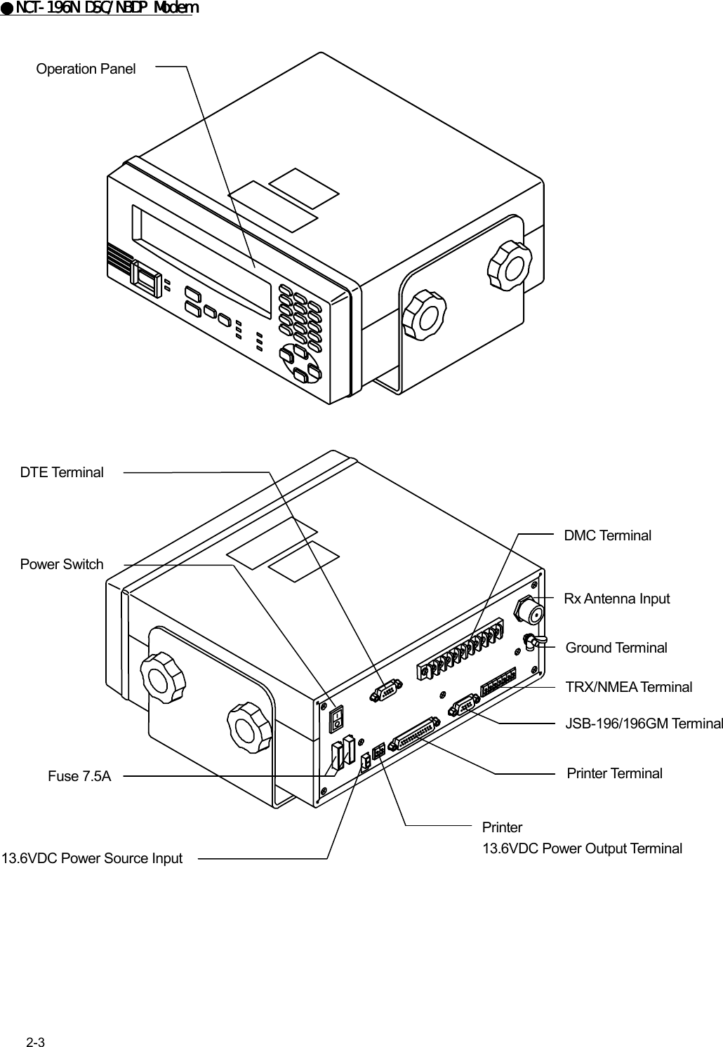
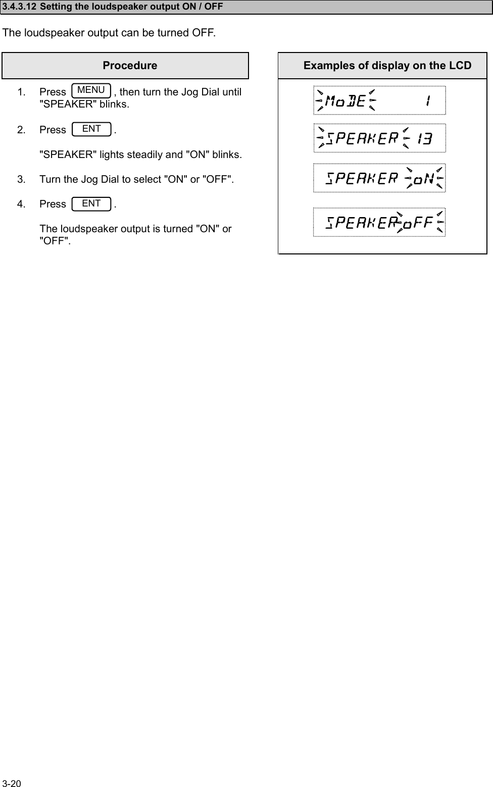
![xiiiTransmitting Distress Calls 3The NCT-196N enables an operator to create and edit messages for transmission. Procedure1. Confirm that the "DSC watching" screen is displayed.2. Press .The "MENU #1-EDIT&CALL" screen is displayed.3. Press and then to select “3. Distress call”.The "Distress Call" screen is displayed as follows. Then setup these items except for “Address”and “End of sequence” properly.4. Open the cover on the left and press for 3.5 seconds at least.5. The following screen is displayed and the distress transmission is started.If a printer is connected, it prints out the distress message.The distress message is transmitted for 5 times successively. • If break the distress transmission, press . DSC watching 06.Sep.2001(Thu) 01:26 12゚34’N123゚45’E SPEED:12.4KT at 01:26 Self-ID = XXXXXXXXX [UTC]MENU MENU #1-EDIT&CALL Select no. 1.Individual call 2.Acknowledgement call 3.Distress call 4.Distress relay call 5.Auto/semi-auto call 6.All ships call Use and to scroll the screen. 7.Group call 8.Area call 9.Position request 10.Polling call 11.Test call▲▼3ENT DISTRESS CALL Transmissible Address : XXXXXXXXX Nature : UNDESIGNATED DIST Dist-position : 31゚00’N 135゚00’E Dist-UTC : 01:26 Dist-telecomm : J3E TEL Use and to End of sequence: EOS scroll the screen. Call TX/RX freq: 2,187.5/ 2,187.5 kHz▲▼DISTRESS CALL Transmitting TX frequency : 2,187.5 kHz TX date&time :06.Sep.2001(Thu) 01:26 1/ 5DISTRESSNote STOP](https://usermanual.wiki/Japan-Radio/JSS-296.Pages-1-to-77/User-Guide-321010-Page-15.png)
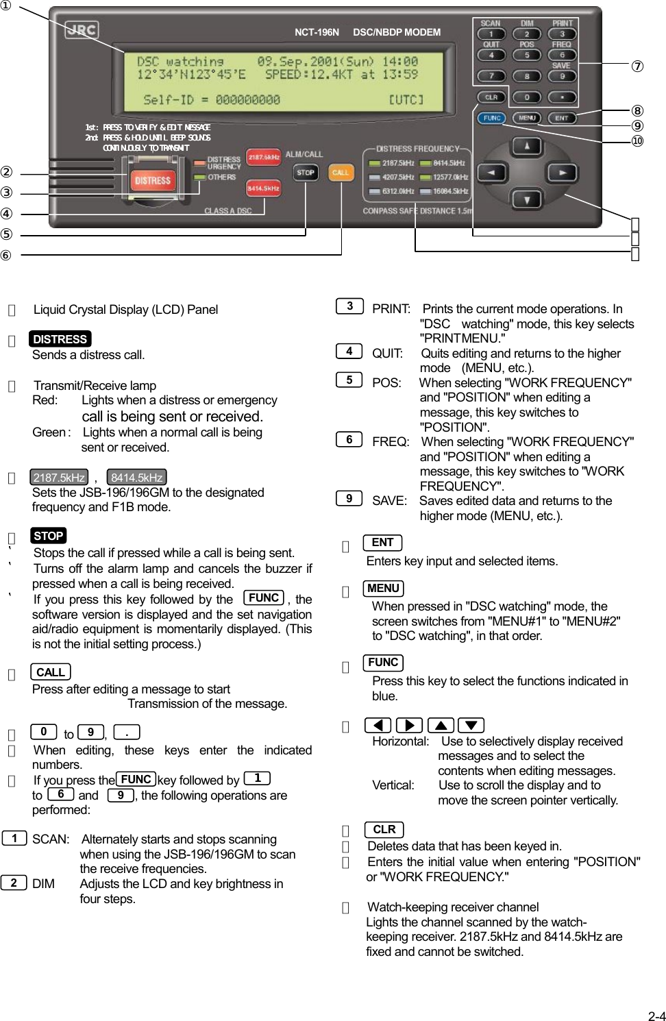

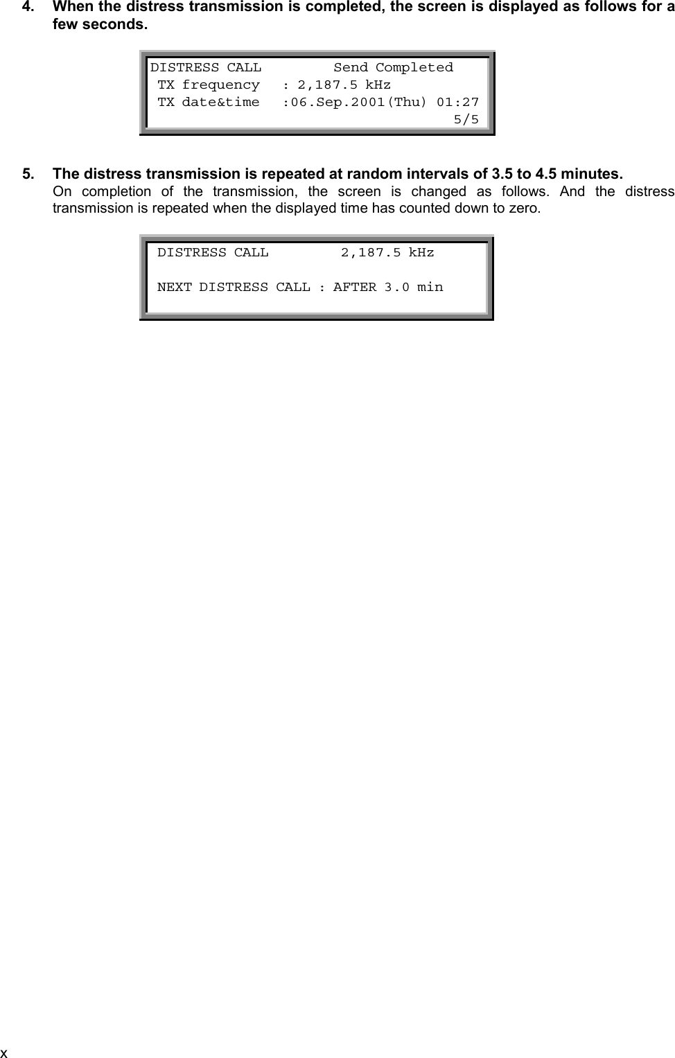
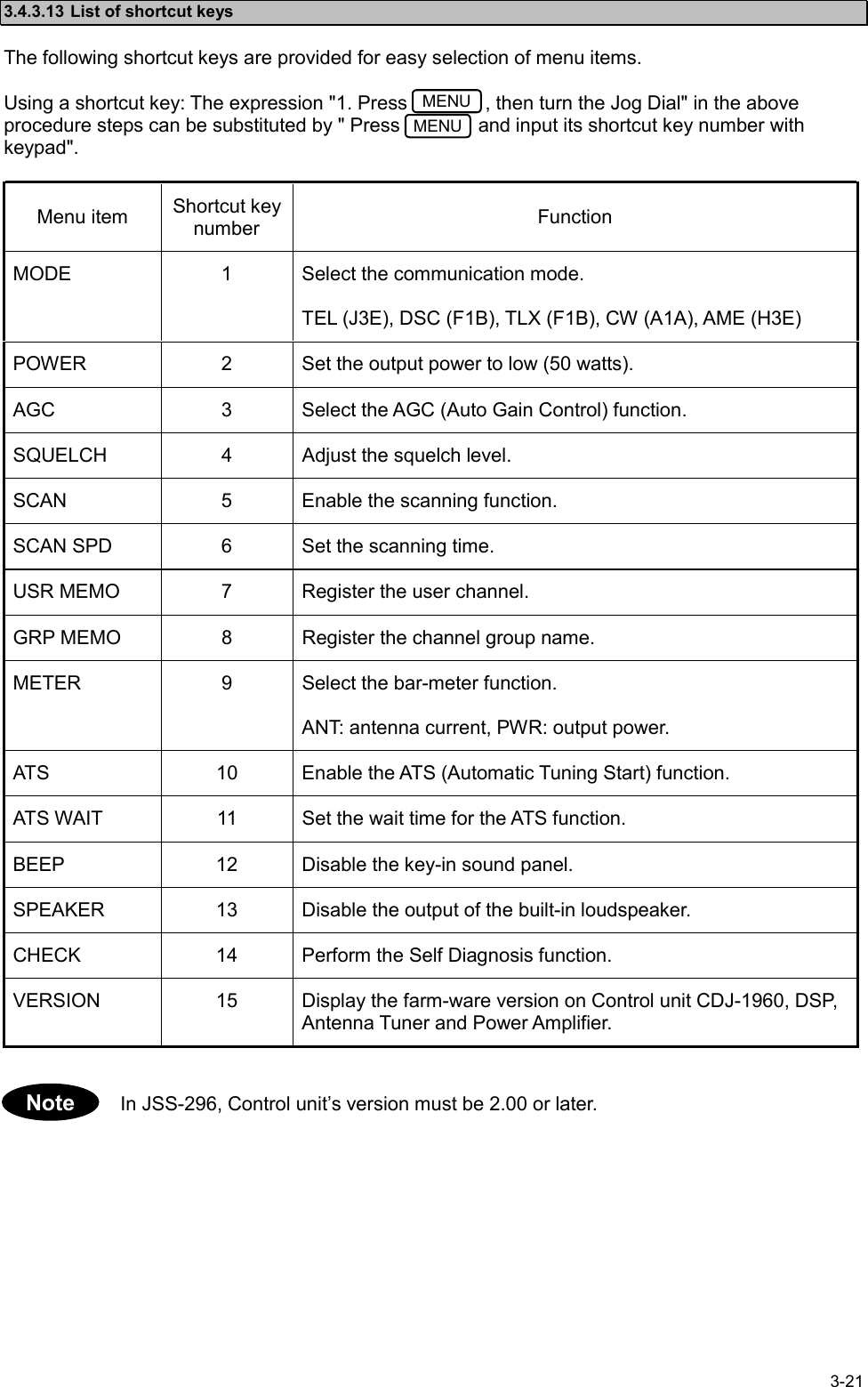
![3-23.2 MODEM MODE ChangeAfter turning ON the system, according to the mode setting when the system was turned OFF last,the NCT-196N selects the mode. However if needed to change the mode, operate the system inaccordance with the following procedure.3.2.1 MODE change to DSC1. Confirm that the NCT-196N displays the following screen.2. Press on the panel of the NCT-196N.It is also available to press the keys concerning to Distress( , , or ) .3. After the mode change completed, the following initial display appears.The mode of the peripheral units such as JSB-196/196GM Radiotelephone and NDZ-127J DTE is changed to DSC mode simultaneously by the above-mentionedoperation. DSC watching 06.Sep.2001(Thu) 01:26 12゚34’N123゚45’E SPEED:12.4KT at 01:26 Self-ID = XXXXXXXXX [UTC]ENTNoteDISTRESS2187.5kHz 8414.5kHz DSC watching 06.Sep.2001(Thu) 01:26-------------------------------------------- MODE: XXXX (Press ENT to set DSC mode.)--------------------------------------------Note](https://usermanual.wiki/Japan-Radio/JSS-296.Pages-1-to-77/User-Guide-321010-Page-38.png)
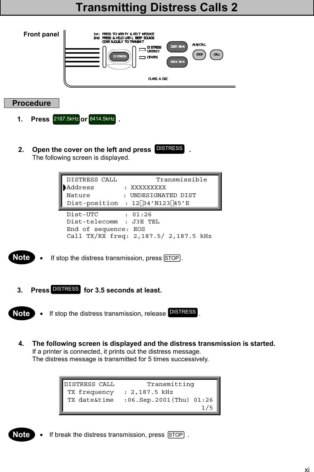
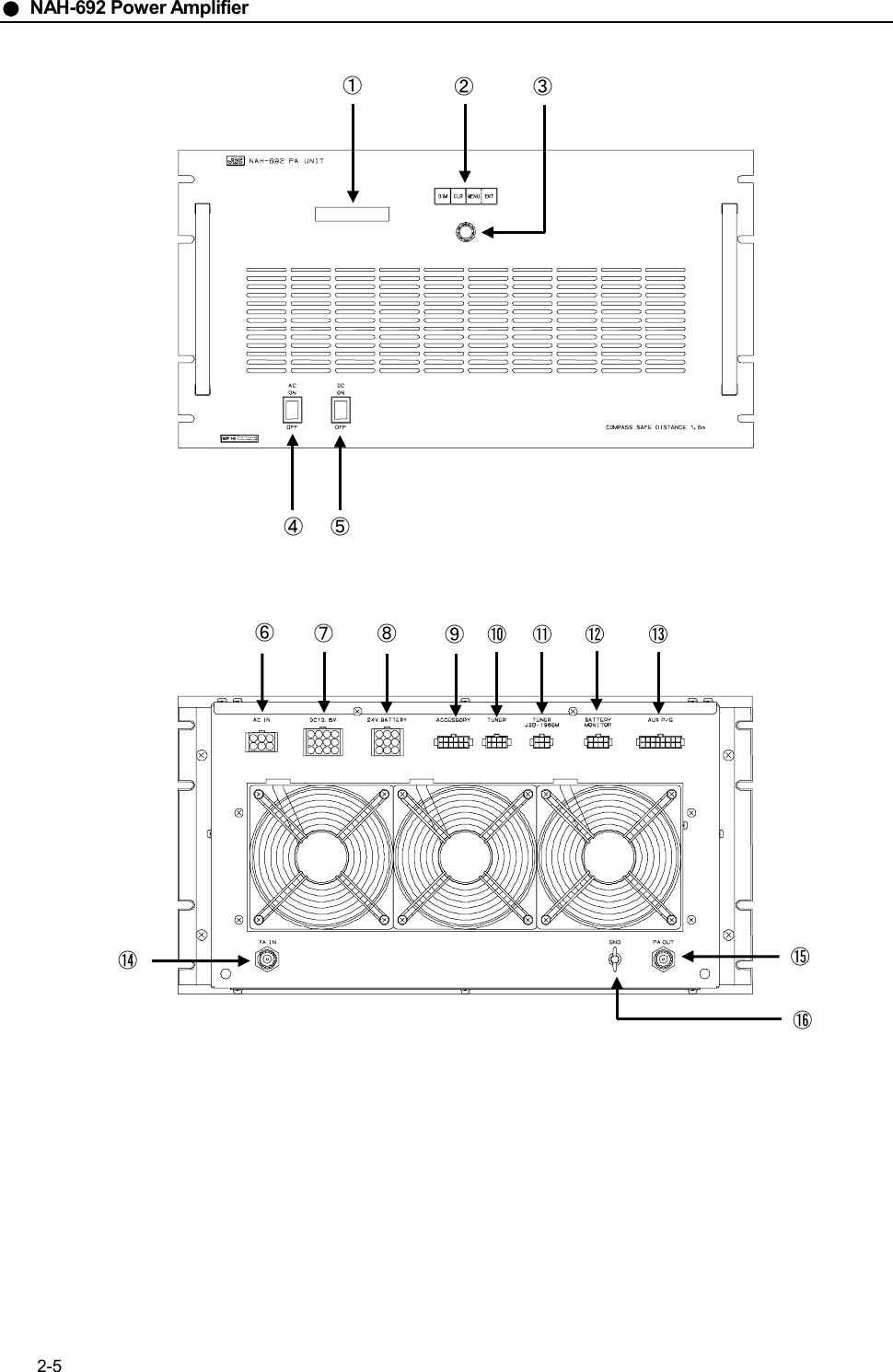
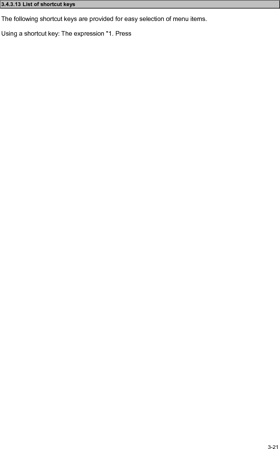
![3-33.2.2 MODE change to TLX1. Confirm that the NDZ-127J displays the following screen in any mode except for TLX.2. Press Enter on the NDF-268 Keyboard.3. After the mode change completed, the following initial display appears.The mode of the peripheral units such as JSB-196/196GM and NCT-196N is changedto TLX mode simultaneously by the above-mentioned operation.Note [TLX] Tx=12345.6kHz / Rx=12345.6kHz (ITU CH= 0) 10-APR-2002 12:00(LT) Loc: N19.00 E115.30 at 11:00(UTC) File Mode Connect Service System Help [ STATUS INFO ] Scanning info Tuner/Tx.POWER [No scanning] TUNER :[READY] Tx.POWER:[FULL] Last status messagesMove the cursor to the item you want with ↑,↓,→,← then press EnterST-BYFile [xxx] Tx=12345.6kHz / Rx=12345.6kHz (ITU CH= 0) 10-APR-2002 12:00(LT) Loc: N19.00 E115.30 at 11:00(UTC) File Mode Connect Service System Help [ STATUS INFO ] Scanning info Tuner/Tx.POWER [No scanning] TUNER :[READY] Tx.POWER:[FULL] Last status messages Press Enter key to set NBDP mode...Move the cursor to the item you want with ↑,↓,→,← then press Enter](https://usermanual.wiki/Japan-Radio/JSS-296.Pages-1-to-77/User-Guide-321010-Page-39.png)
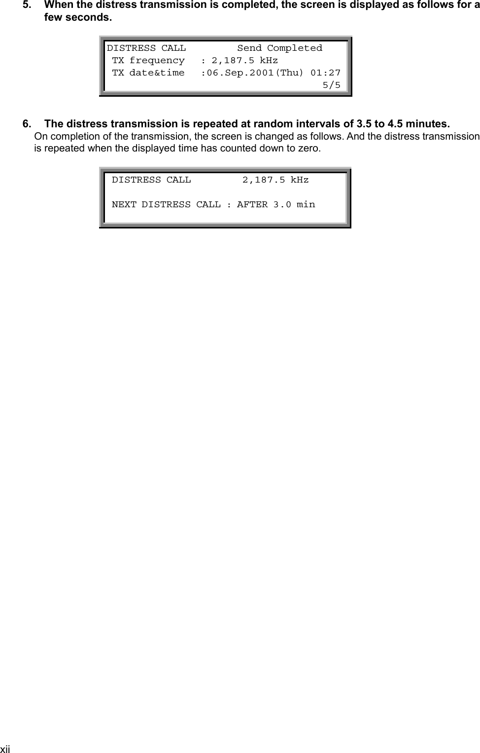
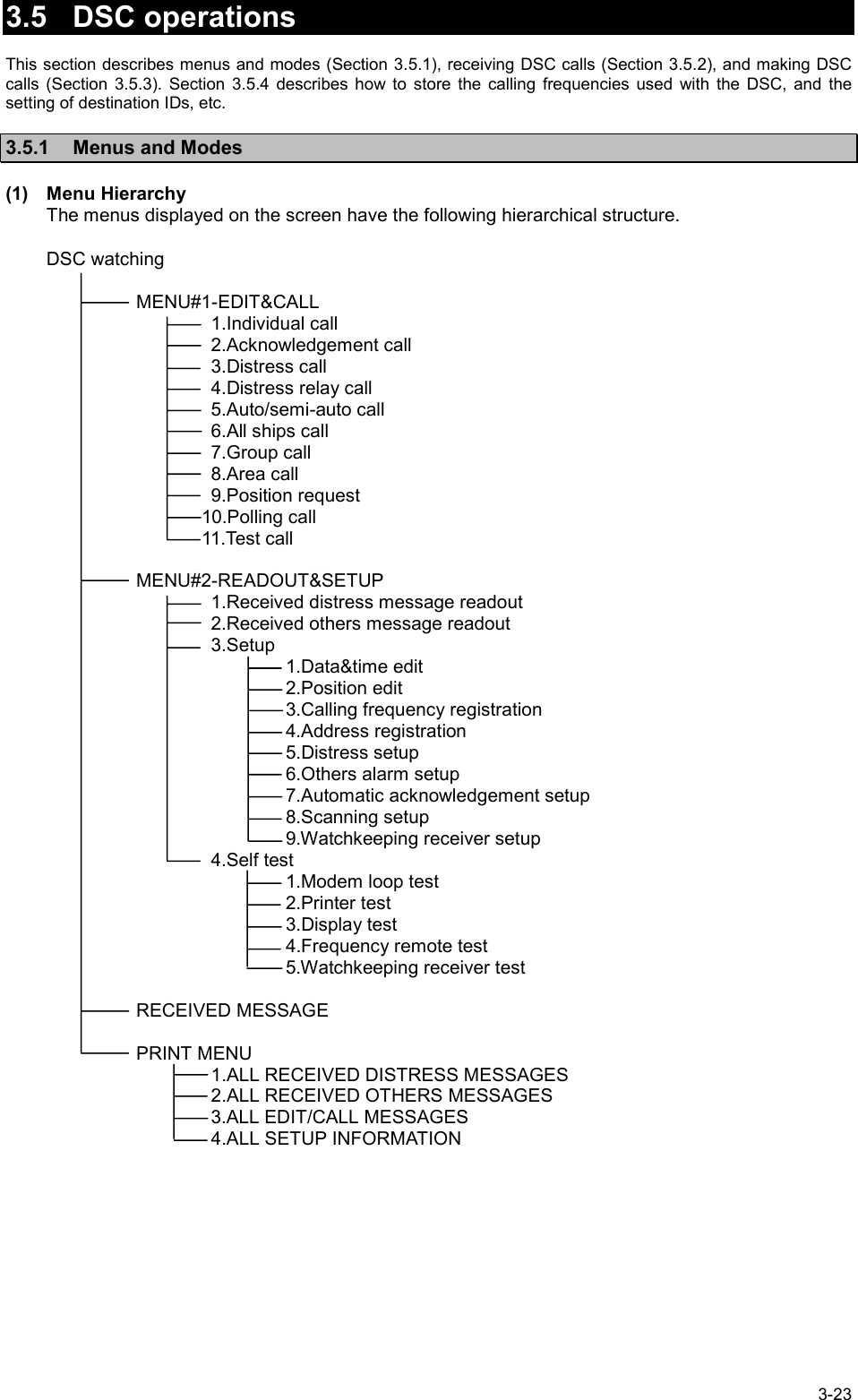
![3-43.3 Setting Position and Time Data3.3.1 Setting the Internal Clock(DATE & TIME EDIT)The built-in clock of the NCT-196N can be set the date (year, month, and day) and time manually. However if theNCT-196N is connected to a navigation aid, the manual input data is overwritten because the navigation aid haspriority over the NCT-196N internal clock. The standard time is UTC but it is possible to input time difference fromthe UTC and display the current local time (LT). Note that in case of no navigation aid connecting, time data shouldbe set to the present time manually and periodically because the time data input manually is treated as invalid dataand deleted after 23.5 hours past. Procedure1. Check that the "DSC watching" screen is displayed.If the "DSC watching" screen is not displayed, press 3 times in succession to switch to the"DSC watching" screen.On the screen mark is displayed when no printer is connected to the NCT-196N.2. Press .The "MENU#1-EDIT&CALL" screen is displayed.STOPMENU DSC watching 06.Sep.2001(Thu) 01:26 P 12゚34’N123゚45’E SPEED:12.4KT at 01:26 Self-ID = XXXXXXXXX [UTC] MENU #1-EDIT&CALL Select no. 1.Individual call 2.Acknowledgement call 3.Distress call 4.Distress relay call 5.Auto/semi-auto call 6.All ships call Use and to scroll. 7.Group call 8.Area call 9.Position request 10.Polling call 11.Test call▼▲PNoteIf the position and time data from navigation aids such as a GPS receiver stop for more than 5 minutes,or if it past for more than 4 hours without further input after entering position and time data manually, theNCT-196N sounds alarm. When the alarm sounding in condition of navigation aid connecting, checkthe navigation aid or the connections to the NCT-196N. Or when the alarm sounding in condition of nonavigation aid connecting, enter the new position and time data manually.ATTENTION](https://usermanual.wiki/Japan-Radio/JSS-296.Pages-1-to-77/User-Guide-321010-Page-40.png)
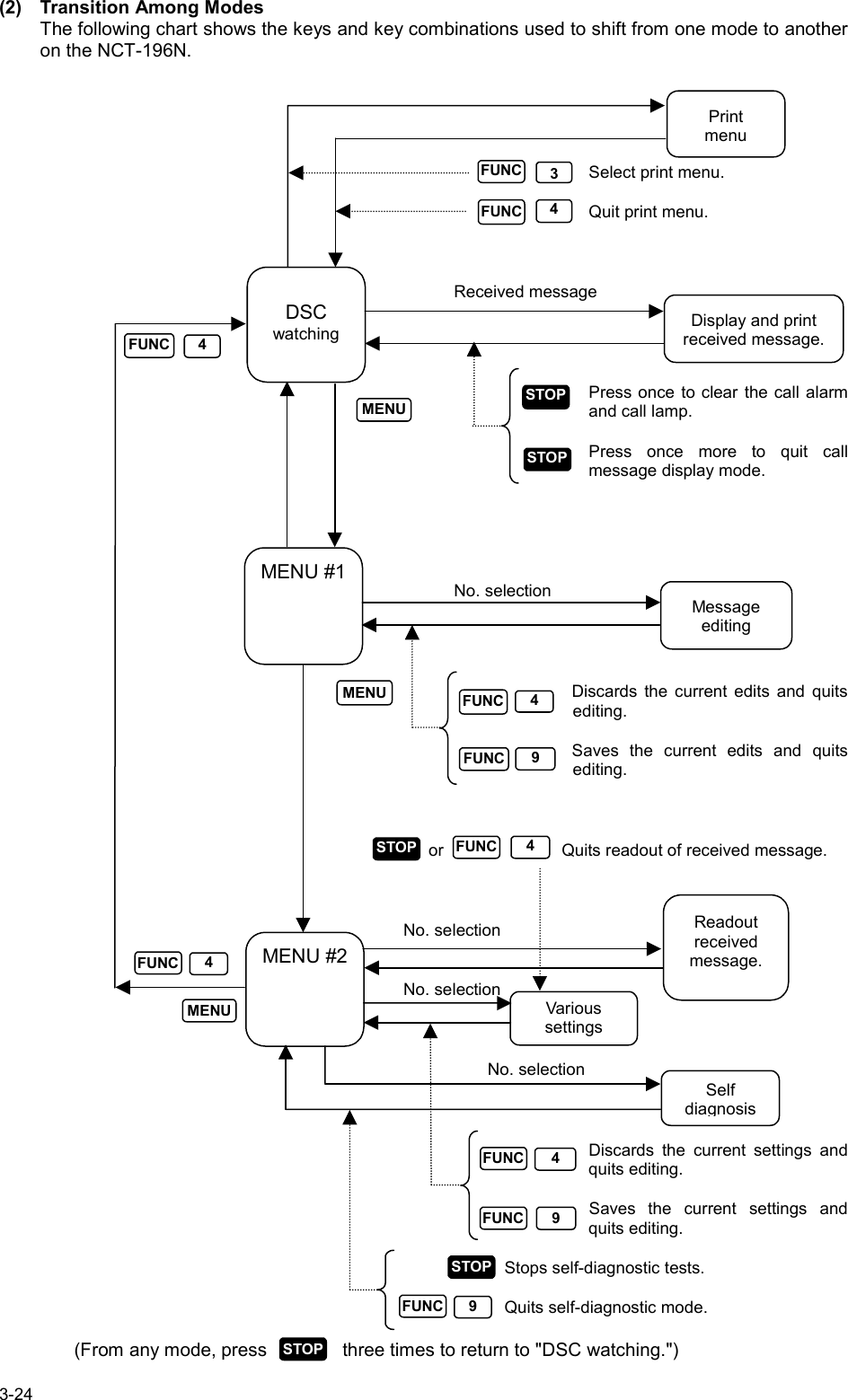
![3-26Use and to scroll.(2) Reading a Distress/Urgent MessageMessages are loaded at the "DSC watching" screen. ATTENTION To prevent unnecessary distress message relay transmission, the NCT-196N automatically deletes distress/urgency messages after 48 hours since these received. Thus the procedure above- mentioned to read distress message received is invalid at that time. Procedure1. Check that the "DSC watching" screen is displayed.If the "DSC watching" screen is not displayed, press 3 times in succession to switch to the"DSC watching" screen.On the screen mark is displayed when no printer is connected to the NCT-196N.2. Press .The "MENU#1-EDIT&CALL" screen is displayed.3. Press again.The "MENU#2-READOUT&SETUP" screen is displayed.STOPMENUMENU DSC watching 06.Sep.2001(Thu) 01:26 P 12゚34’N123゚45’E SPEED:12.4KT at 01:26 Self-ID = XXXXXXXXX [UTC] MENU #1-EDIT&CALL Select no. 1.Individual call 2.Acknowledgement call 3.Distress call 4.Distress relay call 5.Auto/semi-auto call 6.All ships call Use and to scroll. 7.Group call 8.Area call 9.Position request 10.Polling call 11.Test call▼▲ MENU #2 -READOUT&SETUP Select no. 1.Received distress message readout 2.Received others message readout 3.Setup 4.Self test▲▼PNote](https://usermanual.wiki/Japan-Radio/JSS-296.Pages-1-to-77/User-Guide-321010-Page-62.png)
![3-32 INDIVIDUAL CALL Transmissible Address :XXXXXXXXX Category :ROUTINE Telecommand-1 :J3E TEL Telecommand-2 :NO INFORMATION Ship’s position:12 ゚34’N123 ゚45’E Call TX/RX freq: 4,208.0/ 4,219.5 kHzUse and toscroll the screen. ProcedureExample: ROUTINE procedure.1. Check that the "DSC watching" screen is displayed.2. Press .The "MENU#1-EDIT&CALL" screen is displayed.3. Press , and then press .The "INDIVIDUAL CALL" screen is displayed.The following items have been set in this example.「Address」:XXXXXXXXX「Category」:ROUTINE「Telecommand-1」:J3E TEL「Telecommand-2」:NO INFORMATION「Ship’s position」:12 ゚34’N123 ゚45’E「Call TX/RX freq」:4,208.0/4,219.5 kHzMENU1ENT▲▼ DSC watching 06.Sep.2001(Thu) 01:26 12゚34’N123゚45’E SPEED:12.4KT at 01:26 Self-ID = XXXXXXXXX [UTC] MENU #1-EDIT&CALL Select no. 1.Individual call 2.Acknowledgement 3.Distress call 4.Distress relay call 5.Auto/semi-auto call 6.All ships call Use and to scroll the screen. 7.Group call 8.Area call 9.Position request 10.Polling call 11.Test call▼▲](https://usermanual.wiki/Japan-Radio/JSS-296.Pages-1-to-77/User-Guide-321010-Page-68.png)
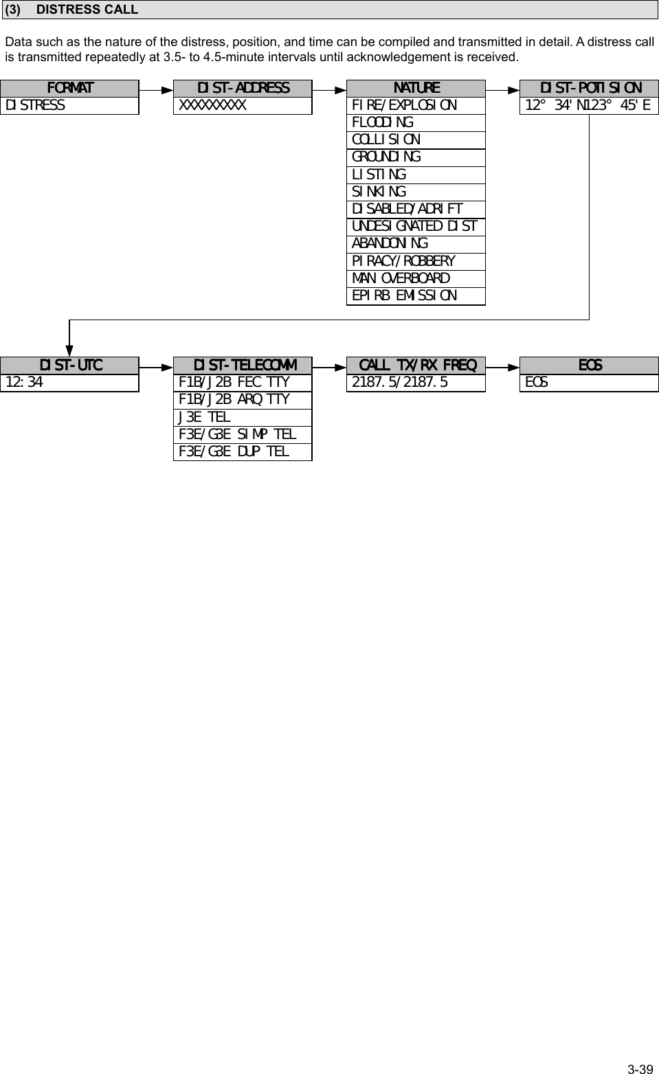
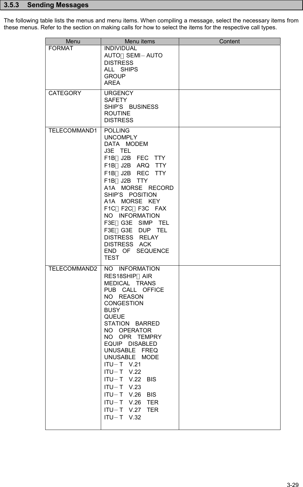
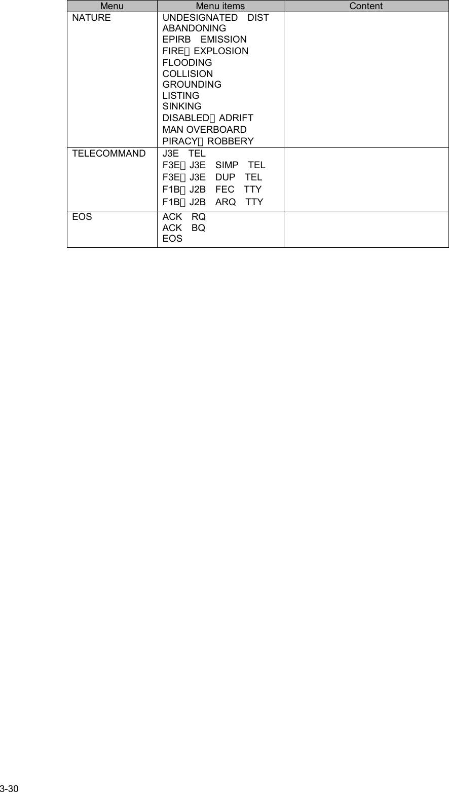
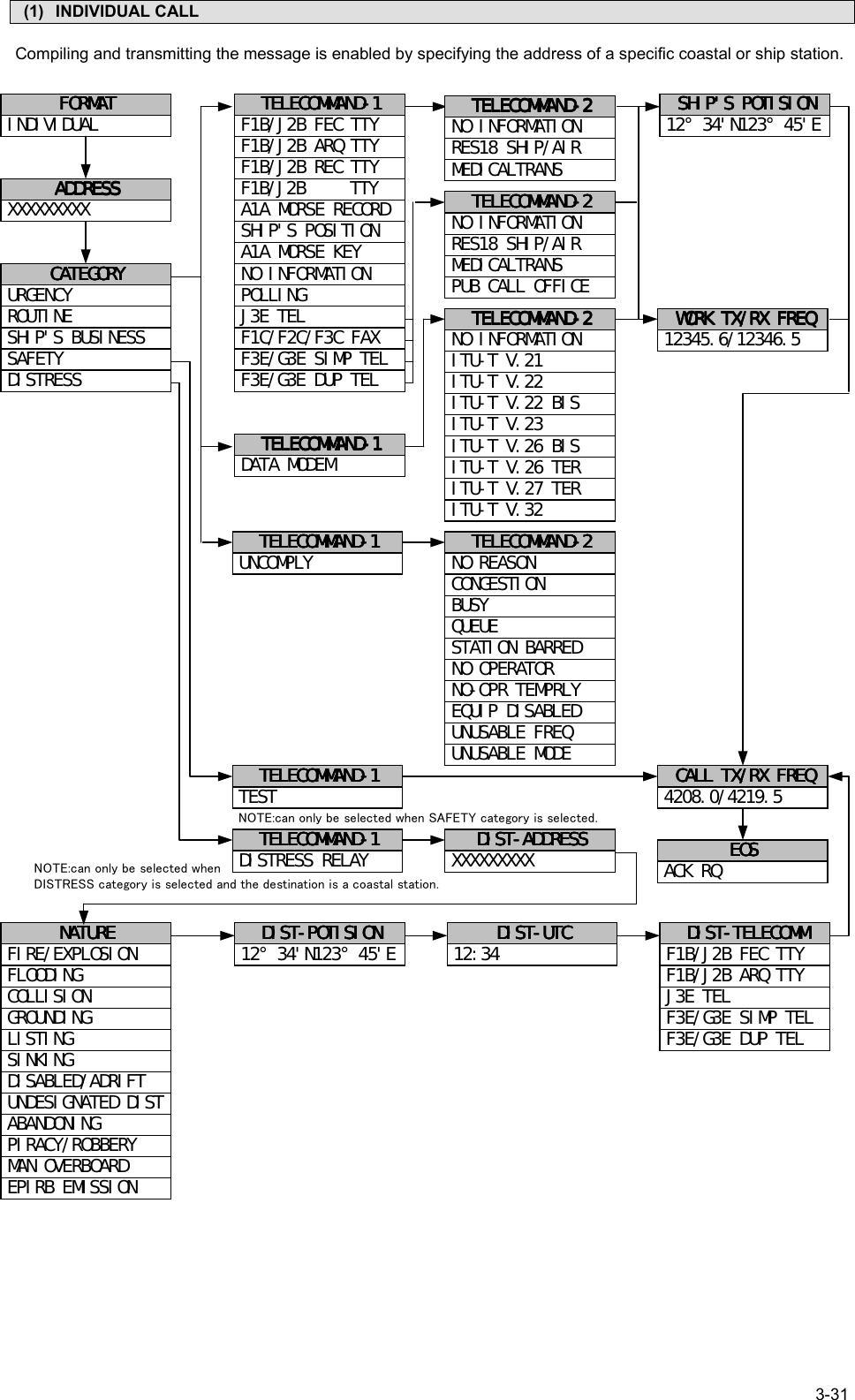
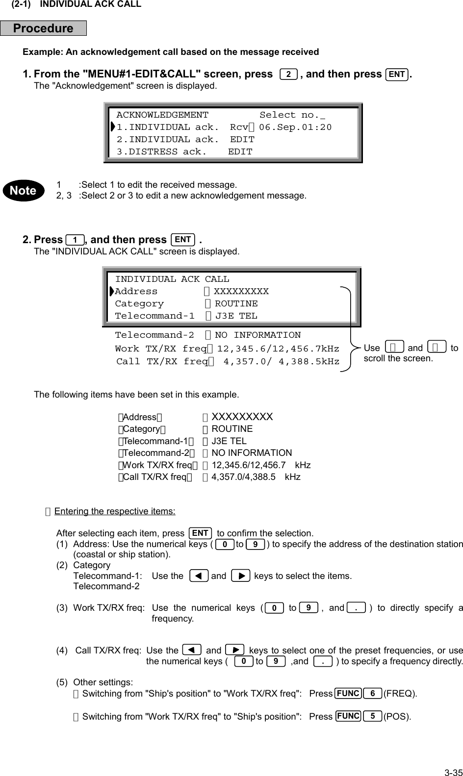
![3-34(2) ACKNOWLEDGEMENT CALLIn the event that the received general message requests acknowledgement, a message of acknowledgement isautomatically produced. Creating and transmitting a distress acknowledgement message is also possible.FORMATFORMATFORMATFORMATINDIVIDUALADDRESSADDRESSADDRESSADDRESSXXXXXXXXXCATEGORYCATEGORYCATEGORYCATEGORYURGENCYSAFETYSHIP'S BUSINESSROUTINEDISTRESSTELECOMMAND-1TELECOMMAND-1TELECOMMAND-1TELECOMMAND-1J3E TELF1B/J2B FEC TTYF1B/J2B ARQ TTYF1B/J2B REC TTYF1B/J2B TTYA1A MORSE RECORDSHIP'S POSITIONA1A MORSE KEYF1C/F2C/F3C FAXNO INFORMATIONF3E/G3E SIMP TELF3E/G3E DUP TELPOLLINGUNCOMPLYTELECOMMAND-2TELECOMMAND-2TELECOMMAND-2TELECOMMAND-2NO INFORMATIONRES18 SHIP/AIRMEDICALTRANSPUB CALL OFFICETELECOMMAND-2TELECOMMAND-2TELECOMMAND-2TELECOMMAND-2NO INFORMATIONITU-T V.21ITU-T V.22ITU-T V.22 BISITU-T V.23ITU-T V.26 BISITU-T V.26 TERITU-T V.27 TERITU-T V.32TELECOMMAND-2TELECOMMAND-2TELECOMMAND-2TELECOMMAND-2NO REASONCONGESTIONBUSYQUEUESTATION BARREDNO OPERATORNO-OPR TEMPRLYEQUIP DISABLEDUNUSABLE FREQUNUSABLE MODESHIP'S POTISIONSHIP'S POTISIONSHIP'S POTISIONSHIP'S POTISION12°34'N123°45'EWORK TX/RX FREQWORK TX/RX FREQWORK TX/RX FREQWORK TX/RX FREQ12345.6/12346.5CALL TX/RX FREQCALL TX/RX FREQCALL TX/RX FREQCALL TX/RX FREQ2187.5/2187.5EOSEOSEOSEOSEOSDIST-ADDRESSDIST-ADDRESSDIST-ADDRESSDIST-ADDRESSNATURENATURENATURENATUREDIST-POTISIONDIST-POTISIONDIST-POTISIONDIST-POTISION12°34'N123°45'EDIST-UTCDIST-UTCDIST-UTCDIST-UTC12:34DIST-TELECOMMDIST-TELECOMMDIST-TELECOMMDIST-TELECOMMJ3E TELF1B/J2B FEC TTYF1B/J2B ARQ TTYF3E/G3E SIMP TELF3E/G3E DUP TELTELECOMMAND-1TELECOMMAND-1TELECOMMAND-1TELECOMMAND-1DATA MODEMTELECOMMAND-1TELECOMMAND-1TELECOMMAND-1TELECOMMAND-1XXXXXXXXXALL SHIPSDISTRESSCATEGORYCATEGORYCATEGORYCATEGORYDISTRESS ACKTELECOMMAND-2TELECOMMAND-2TELECOMMAND-2TELECOMMAND-2NO INFORMATIONRES18 SHIP/AIRMEDICALTRANSCALL TX/RX FREQCALL TX/RX FREQCALL TX/RX FREQCALL TX/RX FREQ4208.0/4219.5EOSEOSEOSEOSACK BQTELECOMMAND-1TELECOMMAND-1TELECOMMAND-1TELECOMMAND-1UNDESIGNATED DISTABANDONINGEPIRB EMISSIONFIRE/EXPLOSIONFLOODINGCOLLISIONGROUNDINGLISTINGSINKINGDISABLED/ADRIFTPIRACY/ROBBERYMAN OVERBOARD[Fixed][Fixed]](https://usermanual.wiki/Japan-Radio/JSS-296.Pages-1-to-77/User-Guide-321010-Page-70.png)
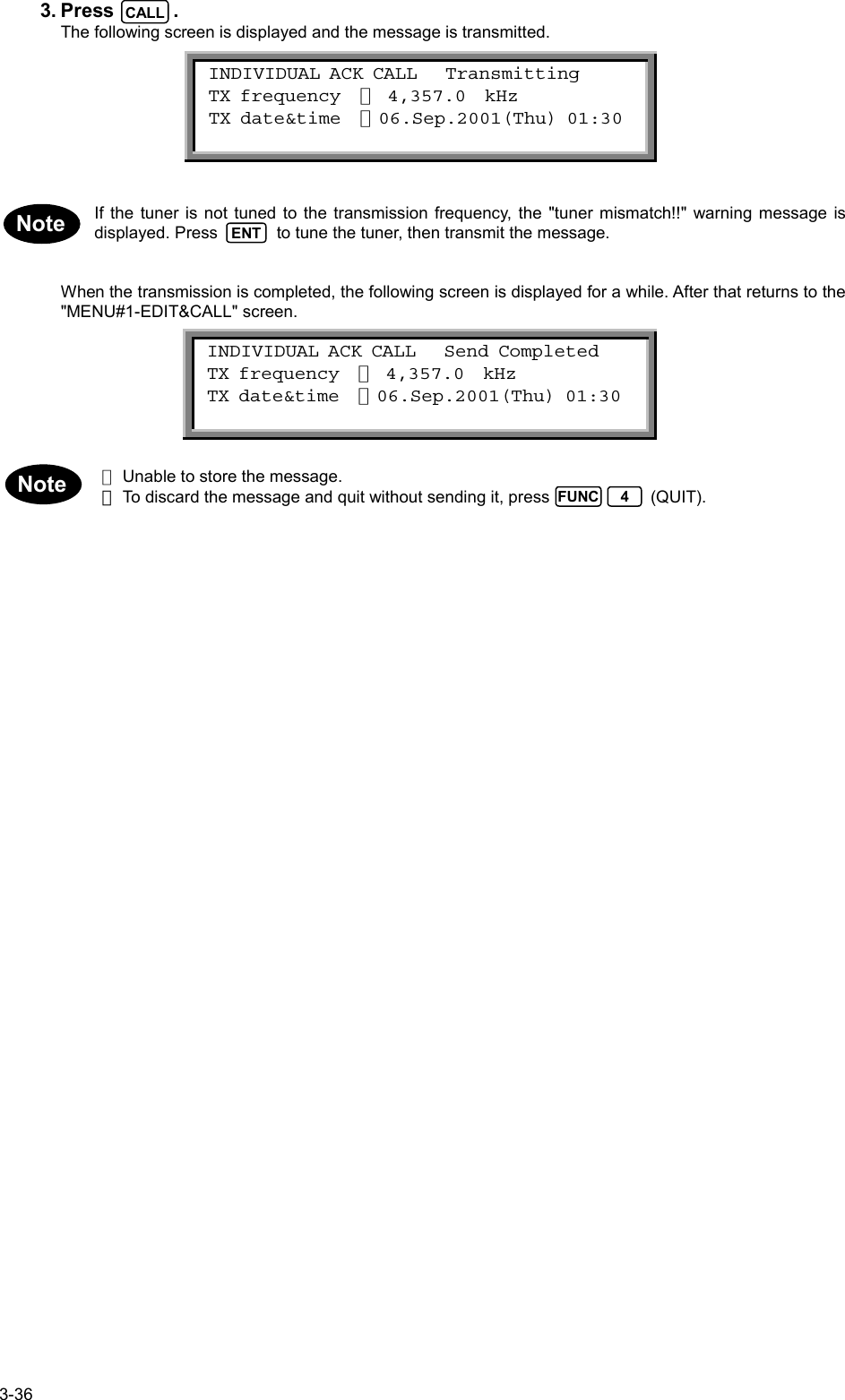
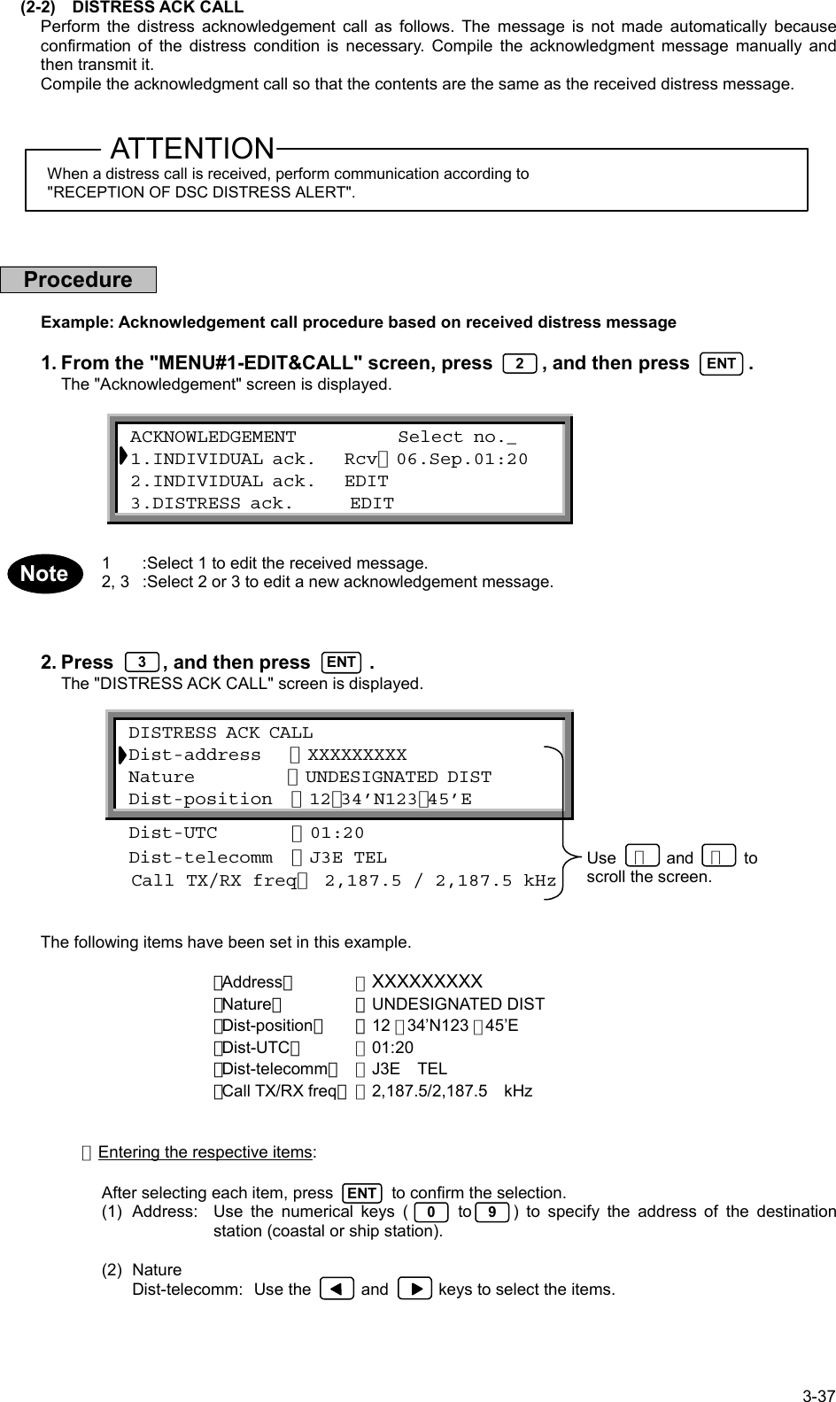
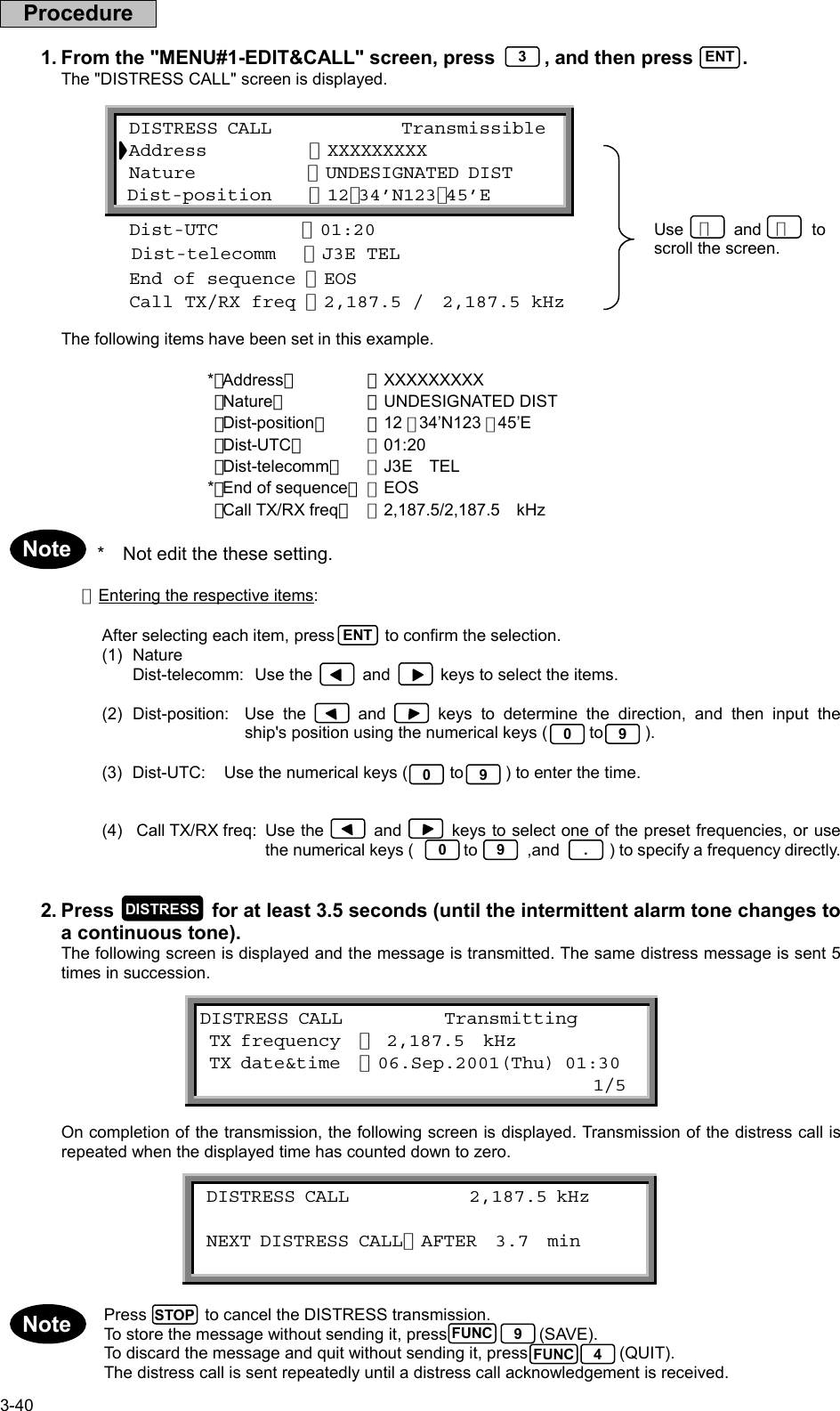
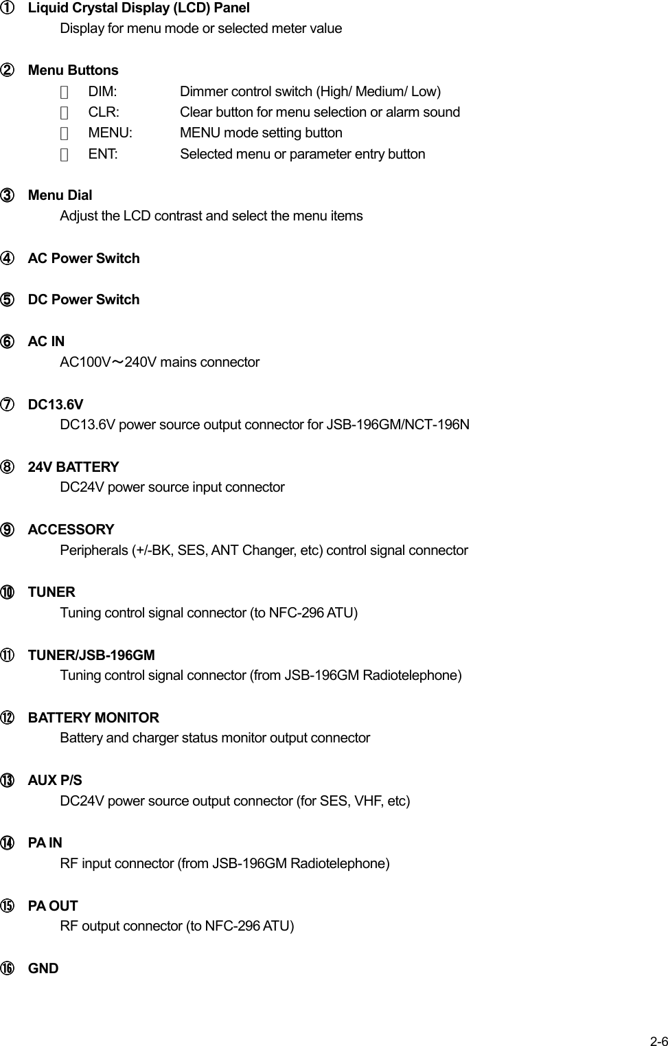
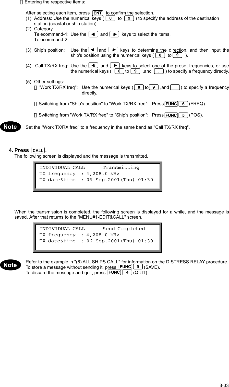
![3-38(3) Dist-position: Use the and keys to determine the direction, and then input the ship'sposition using the numerical keys ( to ).(4) Dist-UTC: Use the numerical keys ( to ) to enter the time.(5) Call TX/RX freq: Use the and keys to select one of the preset frequencies, or usethe numerical keys ( to ,and ) to specify a frequency directly.3. Press .The following screen is displayed and the message is transmitted.If the tuner is not tuned to the transmission frequency, the following screen is displayed. Press totune the tuner and then transmit the message.When the transmission is completed, the following screen is displayed and, after a brief interval, operationreturns to the "MENU#1-EDIT&CALL" screen.・ Unable store the message.・ To discard the message and quit without sending it, press (QUIT).090 9CALL DISTRESS ACK CALL Transmitting TX frequency : 2,187.5 kHz TX date&time :06.Sep.2001(Thu) 01:30 DISTRESS ACK CALL Send Completed TX frequency : 2,187.5 kHz TX date&time :06.Sep.2001(Thu) 01:30FUNC 4 tuner mismatch ! ! Press [ENT] key to tune & send Press [CLR] key to sendENTNote0 9 .](https://usermanual.wiki/Japan-Radio/JSS-296.Pages-1-to-77/User-Guide-321010-Page-74.png)